EP3111788A1 - Surgical face guard, surgical frame, surgical polarizing shield, and surgical system - Google Patents
Surgical face guard, surgical frame, surgical polarizing shield, and surgical system Download PDFInfo
- Publication number
- EP3111788A1 EP3111788A1 EP16746382.7A EP16746382A EP3111788A1 EP 3111788 A1 EP3111788 A1 EP 3111788A1 EP 16746382 A EP16746382 A EP 16746382A EP 3111788 A1 EP3111788 A1 EP 3111788A1
- Authority
- EP
- European Patent Office
- Prior art keywords
- frame
- shield
- polarization
- surgical
- face guard
- Prior art date
- Legal status (The legal status is an assumption and is not a legal conclusion. Google has not performed a legal analysis and makes no representation as to the accuracy of the status listed.)
- Ceased
Links
- BRJCIHFMBRRARS-HLQBBKRNSA-N C/C=C/C[NH+](/C(/C)=C/C)[O-] Chemical compound C/C=C/C[NH+](/C(/C)=C/C)[O-] BRJCIHFMBRRARS-HLQBBKRNSA-N 0.000 description 1
Images







Classifications
-
- A—HUMAN NECESSITIES
- A61—MEDICAL OR VETERINARY SCIENCE; HYGIENE
- A61B—DIAGNOSIS; SURGERY; IDENTIFICATION
- A61B34/00—Computer-aided surgery; Manipulators or robots specially adapted for use in surgery
- A61B34/25—User interfaces for surgical systems
-
- A—HUMAN NECESSITIES
- A61—MEDICAL OR VETERINARY SCIENCE; HYGIENE
- A61F—FILTERS IMPLANTABLE INTO BLOOD VESSELS; PROSTHESES; DEVICES PROVIDING PATENCY TO, OR PREVENTING COLLAPSING OF, TUBULAR STRUCTURES OF THE BODY, e.g. STENTS; ORTHOPAEDIC, NURSING OR CONTRACEPTIVE DEVICES; FOMENTATION; TREATMENT OR PROTECTION OF EYES OR EARS; BANDAGES, DRESSINGS OR ABSORBENT PADS; FIRST-AID KITS
- A61F9/00—Methods or devices for treatment of the eyes; Devices for putting in contact-lenses; Devices to correct squinting; Apparatus to guide the blind; Protective devices for the eyes, carried on the body or in the hand
- A61F9/02—Goggles
- A61F9/022—Use of special optical filters, e.g. multiple layers, filters for protection against laser light or light from nuclear explosions, screens with different filter properties on different parts of the screen; Rotating slit-discs
- A61F9/023—Use of special optical filters, e.g. multiple layers, filters for protection against laser light or light from nuclear explosions, screens with different filter properties on different parts of the screen; Rotating slit-discs with variable transmission, e.g. photochromic
-
- A—HUMAN NECESSITIES
- A61—MEDICAL OR VETERINARY SCIENCE; HYGIENE
- A61F—FILTERS IMPLANTABLE INTO BLOOD VESSELS; PROSTHESES; DEVICES PROVIDING PATENCY TO, OR PREVENTING COLLAPSING OF, TUBULAR STRUCTURES OF THE BODY, e.g. STENTS; ORTHOPAEDIC, NURSING OR CONTRACEPTIVE DEVICES; FOMENTATION; TREATMENT OR PROTECTION OF EYES OR EARS; BANDAGES, DRESSINGS OR ABSORBENT PADS; FIRST-AID KITS
- A61F9/00—Methods or devices for treatment of the eyes; Devices for putting in contact-lenses; Devices to correct squinting; Apparatus to guide the blind; Protective devices for the eyes, carried on the body or in the hand
- A61F9/02—Goggles
- A61F9/025—Special attachment of screens, e.g. hinged, removable; Roll-up protective layers
-
- G—PHYSICS
- G02—OPTICS
- G02B—OPTICAL ELEMENTS, SYSTEMS OR APPARATUS
- G02B30/00—Optical systems or apparatus for producing three-dimensional [3D] effects, e.g. stereoscopic images
- G02B30/20—Optical systems or apparatus for producing three-dimensional [3D] effects, e.g. stereoscopic images by providing first and second parallax images to an observer's left and right eyes
- G02B30/22—Optical systems or apparatus for producing three-dimensional [3D] effects, e.g. stereoscopic images by providing first and second parallax images to an observer's left and right eyes of the stereoscopic type
- G02B30/25—Optical systems or apparatus for producing three-dimensional [3D] effects, e.g. stereoscopic images by providing first and second parallax images to an observer's left and right eyes of the stereoscopic type using polarisation techniques
-
- G—PHYSICS
- G02—OPTICS
- G02C—SPECTACLES; SUNGLASSES OR GOGGLES INSOFAR AS THEY HAVE THE SAME FEATURES AS SPECTACLES; CONTACT LENSES
- G02C7/00—Optical parts
- G02C7/12—Polarisers
-
- G—PHYSICS
- G02—OPTICS
- G02C—SPECTACLES; SUNGLASSES OR GOGGLES INSOFAR AS THEY HAVE THE SAME FEATURES AS SPECTACLES; CONTACT LENSES
- G02C9/00—Attaching auxiliary optical parts
-
- H—ELECTRICITY
- H04—ELECTRIC COMMUNICATION TECHNIQUE
- H04N—PICTORIAL COMMUNICATION, e.g. TELEVISION
- H04N13/00—Stereoscopic video systems; Multi-view video systems; Details thereof
- H04N13/30—Image reproducers
- H04N13/332—Displays for viewing with the aid of special glasses or head-mounted displays [HMD]
- H04N13/337—Displays for viewing with the aid of special glasses or head-mounted displays [HMD] using polarisation multiplexing
-
- G—PHYSICS
- G02—OPTICS
- G02C—SPECTACLES; SUNGLASSES OR GOGGLES INSOFAR AS THEY HAVE THE SAME FEATURES AS SPECTACLES; CONTACT LENSES
- G02C1/00—Assemblies of lenses with bridges or browbars
- G02C1/02—Bridge or browbar secured to lenses without the use of rims
- G02C1/026—Bridge or browbar secured to lenses without the use of rims with auxiliary bars
-
- G—PHYSICS
- G02—OPTICS
- G02C—SPECTACLES; SUNGLASSES OR GOGGLES INSOFAR AS THEY HAVE THE SAME FEATURES AS SPECTACLES; CONTACT LENSES
- G02C11/00—Non-optical adjuncts; Attachment thereof
-
- G—PHYSICS
- G02—OPTICS
- G02C—SPECTACLES; SUNGLASSES OR GOGGLES INSOFAR AS THEY HAVE THE SAME FEATURES AS SPECTACLES; CONTACT LENSES
- G02C11/00—Non-optical adjuncts; Attachment thereof
- G02C11/08—Anti-misting means, e.g. ventilating, heating; Wipers
-
- G—PHYSICS
- G02—OPTICS
- G02C—SPECTACLES; SUNGLASSES OR GOGGLES INSOFAR AS THEY HAVE THE SAME FEATURES AS SPECTACLES; CONTACT LENSES
- G02C2200/00—Generic mechanical aspects applicable to one or more of the groups G02C1/00 - G02C5/00 and G02C9/00 - G02C13/00 and their subgroups
- G02C2200/06—Locking elements
-
- G—PHYSICS
- G02—OPTICS
- G02C—SPECTACLES; SUNGLASSES OR GOGGLES INSOFAR AS THEY HAVE THE SAME FEATURES AS SPECTACLES; CONTACT LENSES
- G02C2200/00—Generic mechanical aspects applicable to one or more of the groups G02C1/00 - G02C5/00 and G02C9/00 - G02C13/00 and their subgroups
- G02C2200/08—Modular frames, easily exchangeable frame parts and lenses
-
- G—PHYSICS
- G02—OPTICS
- G02C—SPECTACLES; SUNGLASSES OR GOGGLES INSOFAR AS THEY HAVE THE SAME FEATURES AS SPECTACLES; CONTACT LENSES
- G02C2200/00—Generic mechanical aspects applicable to one or more of the groups G02C1/00 - G02C5/00 and G02C9/00 - G02C13/00 and their subgroups
- G02C2200/32—Oblong hole
Definitions
- the present disclosure relates to a surgical face guard, a surgical frame, a surgical polarization shield, and a surgery system.
- a video of an endoscope or the like is displayed as a three-dimensional image on a display device during surgery, so that a surgeon is provided with more easily-comprehensible video.
- the three-dimensional image can be shown, as described in Patent Literature 1, for example, by using a head mounted display, which is a display device worn by a surgeon, and causing a shift to occur between a left-eye image signal and a right-eye image signal. Further, by letting a surgeon to wear polarized glasses having a polarization property of enabling three-dimensional viewing, the surgeon is allowed to perform three-dimensional viewing of a video displayed on a monitor or the like which is installed nearby.
- a face shield is made of a transparent sheet-like material such as polyethylene terephthalate (PET), in order not to disturb the field of view of the wearer.
- PET polyethylene terephthalate
- the present disclosure proposes a surgical face guard, a surgical frame, a surgical polarization shield, and a surgery system, which are novel and improved, and with which a three-dimensional image can be used safely during medical treatment.
- a surgical face guard including a frame configured to be worn on a head of a medical worker, and a polarization shield configured to cover at least an in-front-of-eyes part and a part of a side-of-face surface of the medical worker, and have a predetermined polarization property with respect to a three-dimensional image.
- a surgical frame including a frame-front part configured to be placed in front of eyes of a medical worker, a frame-right-side part configured to extend from a right end of the frame-front part; and a frame-left-side part configured to extend from a left end of the frame-front part.
- the frame-right-side part or the frame-left-side part has a projection that protrudes toward an opposite side of a head of the medical worker.
- a surgical polarization shield including a polarization area configured to have a predetermined polarization property with respect to a three-dimensional image, a right-fitting hole configured to fit over a fitting part of a right-fixing member of a frame to be worn on a head of a medical worker, and a left-fitting hole configured to fit over a fitting part of a left-fixing member of the frame.
- a shape of the right-fitting hole is different from a shape of the left-fitting hole.
- a surgery system including a display device configured to display a three-dimensional image, and a surgical face guard including a frame configured to be worn on a head of a medical worker, and a polarization shield configured to cover at least an in-front-of-eyes part and a part of a side-of-face surface of the medical worker, and have a predetermined polarization property with respect to a three-dimensional image.
- FIG. 1 is a schematic perspective view showing the surgical face guard 1 according to an embodiment of the present disclosure.
- the surgical face guard (hereinafter, may also be referred to as "face guard") 1 is worn during surgery by a medical worker such as a surgeon, or a carer of the surgery including an endoscope operator or a nurse.
- the face guard 1 includes a frame 100 and a shield 200 that is supported by the frame 100.
- the frame 100 is a member for, in the state of supporting the shield 200, fixing the shield 200 to the wearer.
- the frame 100 is formed in a glasses-type.
- the shield 200 is placed so as to cover from an in-front-of-eyes part that is the front of the eyes of the wearer to the temples of the wearer that are a part of a side-of-face part.
- the shield 200 is a transparent member that covers at least the in-front-of-eyes part and a part of the side-of-face part in order to prevent blood, body fluids, and the like flown off from a patient from adhering to the face. It is more preferred that the shield 200 have a shape that covers, not only the in-front-of-eyes part, but also up to a side-of-face surface, in order to prevent the splash coming from a side-direction of the face from entering the eyes. From a hygiene perspective, the shield 200 is made of a material capable of being sterilized or is disposable.
- the face guard 1 according to the present embodiment is configured such that the shield 200 is provided so as to be attachable to and detachable from the frame 100. Accordingly, the shield 200 that is disposable can also be used.
- the shield 200 according to the present embodiment has a polarization area.
- the shield 200 according to the present embodiment is a polarization shield on which a polarization area having a predetermined polarization property is provided, in order to correctly view a three-dimensional image displayed on a monitor or the like in a predetermined display state.
- the polarization area of the shield 200 is, for example, a polarization area for three-dimensional viewing having a polarization property for allowing a three-dimensional image displayed on a monitor or the like to be viewed three-dimensionally, or a polarization area for two-dimensional viewing having a polarization property for allowing the three-dimensional image to be viewed two-dimensionally.
- the wearer can view the three-dimensional image in a desired display state by attaching the shield 200 having a corresponding polarization area to the frame 100 in accordance with the desired display state of the three-dimensional image.
- the shield 200 according to the present embodiment has a function of preventing the splash coming from a patient from adhering to the wearer of the face guard 1, and also has a function as polarized glasses through which the wearer can view a three-dimensional image.
- the configuration of the face guard 1 according to the present embodiment will be described in detail.
- FIG. 2 is a perspective view of the frame 100 according to the present embodiment.
- FIG. 3 is a plan view of the frame 100 according to the embodiment.
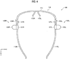
- FIG. 4 is a bottom view of the frame 100 according to the embodiment.
- FIG. 5 is a front view of the frame 100 according to the embodiment.
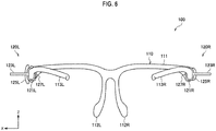
- FIG. 6 is a back view of the frame 100 according to the embodiment.
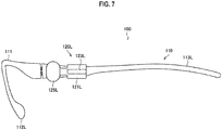
- FIG. 7 is a left-side view of the frame 100 according to the embodiment.
- FIG. 8 is a right-side view of the frame 100 according to the embodiment.
- the frame 100 includes a frame main body 110 of a glasses-type, and fixing members 120 for fixing the shield 200 to the frame main body 110.
- the frame main body 110 includes a frame-front part 111 which is placed in front of the eyes of the wearer of the face guard 1, and temple parts 113R and 113L which are extended from the frame-front part 111 and rest on the right and left ears, respectively, of the wearer.
- the frame-front part 111 is provided over the upper side of the eyes of the wearer, so that the field of view of the wearer can be prevented from being disturbed.
- At the center part of the frame-front part 111 there are provided nose pad parts 112R and 112L, which sandwich the nose of the wearer from both sides, and which are for fixing the frame 100 to the head.
- the temple parts 113R and 113L are provided so as to extend substantially perpendicular to the frame main body 110.
- the temple parts 113R and 113L may each be configured to be connected to the frame main body 110 via a hinge and to be foldable, or may be formed integrally with the frame main body 110.
- fixing members 120R and 120L are provided, respectively, for fixing the shield 200.
- the fixing members 120R and 120L are provided, respectively, for fixing the shield 200 to the frame main body 110.
- the fixing members 120R and 120L are provided at positions at which a right end and a left end of the shield 200 to be fixed to the frame main body 110 are fixed, respectively.
- the fixing members 120R and 120L are provided at parts at which the temples of the wearer who wears the face guard 1 are positioned.
- the fixing members 120R and 120L include attachment parts 121R and 121L, holding parts 123R and 123L, fixing parts 125R and 125L, and the fitting parts 127R and 127L, respectively.
- the attachment parts 121R and 121L are members for attaching the fixing members 120R and 120L to the temple parts 113R and 113L of the frame main body 110, respectively.
- the attachment parts 121R and 121L are formed in ring shapes having substantially the same inner diameters as the outer diameters of the temple parts 113R and 113L, and the temple parts 113R and 113L are inserted into the attachment parts 121R and 121L, so that the attachment parts 121R and 121L are fixed to the temple parts 113R and 113L, respectively, for example.
- the holding parts 123R and 123L are members that are provided so as to protrude toward opposite sides of the head of the wearer of the face guard 1, respectively, in a state in which the fixing members 120R and 120L are fixed to the temple parts 113R and 113L, respectively.
- a medical worker cannot touch an unsterilized object with his/her sterile hands. Accordingly, the wearer of the face guard 1 sometimes gets another worker to attach or detach the face guard 1.
- the frame main body 110 is provided with the holding parts 123R and 123L. The other worker holds the holding parts 123R and 123L that protrude from the right and the left, respectively, of the frame main body 110, to attach or detach the face guard 1.
- the shapes of the holding parts 123R and 123L are not particularly limited as long as the holding parts 123R and 123L can be held by fingers.
- the holding parts 123R and 123L may each be made of a plate-like member whose protruded end part has a shape of a circular arc.
- the flat surfaces of the holding parts 123R and 123L face the vertical direction (z-direction), so that it makes it easy for the other worker to hold the holding parts 123R and 123L, but the direction of the flat surfaces is also not particularly limited.
- the holding parts 123R and 123L may have plate-like members each having a thickness of several millimeters, such that the plate-like members are protruded about 1 to 2 cm from the temple parts 113R and 113L, respectively.
- the fixing parts 125R and 125L are members for fixing the shield 200 to the frame 100.
- the fixing parts 125R and 125L are provided in an extending manner from the outer surfaces of the attachment parts 121R and 121L, along the temple parts 113R and 113L, respectively, and to the side of the frame-front part 111.
- the fixing parts 125R and 125L can be drawn near to or separated away from the temple parts 113R and 113L, respectively, using as the supporting points the parts connected to the attachment parts 121R and 121L, respectively.
- the fixing parts 125R and 125L have the fitting parts 127R and 127L formed on the surfaces that face the temple parts 113R and 113L, respectively.
- the fitting parts 127R and 127L fit into the fixing holes 114R and 114L of the temple parts 113R and 113L, and into fitting holes (for example, reference numerals 215R and 215L shown in FIG. 9 ) of the shield 200 to be fixed to the frame 100, respectively.
- the fixing holes 114R and 114L and the fitting holes are formed in a corresponding manner to the fitting parts 127R and 127L.
- the fitting parts 127R and 127L of the fixing parts 125R and 125L fit into the fitting holes of the shield and the fixing holes 114R and 114L of the temple parts 113R and 113L, respectively. In this way, the shield 200 is fixed to the frame 100.
- the shape of the right-fitting part 127R is different from the shape of the left-fitting part 127L. That is, the right-fitting hole of the shield 200 and the fixing hole 114R of the temple part 113R on the right side are formed in a corresponding manner to the shape of the right-fitting part 127R. In the same manner, the left-fitting hole of the shield 200 and the fixing hole 114L of the temple part 113L on the left side are formed in a corresponding manner to the shape of the left-fitting part 127L.
- the shield 200 to be fixed to the frame 100 has different polarization properties between an area corresponding to the right eye and an area corresponding to the left eye, and if the shield 200 is fixed to the frame 100 inside out, a correct image cannot be provided to the wearer. Accordingly, by making the shape of the right-fitting part 127R different from the shape of the left-fitting part 127L, a correct side to which the shield 200 is to be attached can be shown to the wearer (or the other worker), and the shield 200 can be attached in the state in which the correct side is facing the correct way.
- the right-fitting part 127R is a projection having a horizontally oriented shape
- the left-fitting part 127L is a projection having a vertically oriented shape.
- the shapes of the right-fitting part 127R and the left-fitting part 127L are not limited to such an example, and the shape of the right-fitting part 127R and the shape of the left-fitting part 127L may be any as long as the shapes are different from each other.
- the right fitting hole and the left fitting hole of the shield 200 may be provided in such a way only as to fit over the corresponding fitting parts 127R and 127L of the fixing members 120R and 120L, respectively.
- the relationships between the fitting parts 127R and 127L and the fitting holes hold as long as, even if the shapes themselves are congruent, the orientations are different from each other.
- the one in which the shape of the right-fitting part 127R and the shape of the left-fitting part 127L are congruent but are differently oriented is also included in the one in which the shapes of the right and left fitting parts 127R and 127L are different from each other.
- the frame 100 is made of a material that is resistant to sterilization.
- the frame 100 is made of polycarbonate (PC) or elastomer resin.
- the surface of the frame 100 may be processed to be resistant to sterilization. In this way, the frame 100 can be used repeatedly by performing sterilization.
- FIG. 9 is a schematic plan view showing an example of a shield 200A for three-dimensional viewing.
- FIG. 10 is a schematic plan view showing an example of a shield 200B for two-dimensional viewing.
- the shield 200 according to the present embodiment is a transparent protective member that covers at least an in-front-of-eyes part and a part of a side-of-face part of the wearer of the face guard 1, and is a polarization shield that has a polarization property.
- Examples of the shield 200 according to the present embodiment include the shield 200A for three-dimensional viewing and the shield 200B for two-dimensional viewing.
- the shield 200A for three-dimensional viewing and the shield 200B for two-dimensional viewing may be formed to have the same external shape.
- the shield 200A for three-dimensional viewing is made of one sheet-like material.
- the shield 200A has a size enough to cover at least an in-front-of-eyes part and a part of a side-of-face part of the wearer, and, as shown in FIG. 9 , a notch 211 for letting the nose of the wearer through may be provided at the bottom center in the horizontal direction of a part that covers the in-front-of-eyes part.
- fitting holes 215R and 215L for fixing the shield 200A to the frame 100.
- the fitting holes 215R and 215L have shapes of apertures corresponding to the shapes of the fitting parts 127R and 127L provided to the fixing members 120R and 120L, respectively, of the frame 100. Accordingly, the shape of the right-fitting hole 215R is different from the shape of the left-fitting hole 215L.
- the wearer or another worker orients the position of the shield 200 so as to be fit to the shapes of the fitting parts 127R and 127L of the fixing members 120R and 120L of the frame 100, and thus, the back and front of the shield 200 with respect to the frame 100 can be set correctly.
- the shield 200A there may be provided engaging parts 213R and 213L that engage with the attachment parts 121R and 121L of the fixing members 120R and 120L, respectively.
- the shield 200 is hooked to the attachment parts 121R and 121L, so that it can be made harder for the shield 200 to slip off from the frame 110.
- the shield 200A is made of a transparent sheet-like material such as polycarbonate (PC) or triacetyl cellulose (TAC), in order not to disturb the field of view of the wearer.
- the shield 200A for three-dimensional viewing according to the present embodiment includes a polarization area 210 having a polarization property of enabling three-dimensional viewing of a three-dimensional image displayed on an external monitor.
- the polarization area 210 includes a right-eye polarization area 210R corresponding to the right eye of the wearer of the face guard 1 and a left-eye polarization area 210L corresponding to the left eye of the wearer of the face guard 1.
- the shield 200A for three-dimensional viewing according to the present embodiment is made of a single film which is seamless between the right-eye polarization area 210R and the left-eye polarization area 210L.
- the shield 200A for three-dimensional viewing configures the face guard 1 like the one shown in FIG. 1 , by being attached to the frame 100. Wearing the face guard 1 including the shield 200A for three-dimensional viewing, the wearer can be protected from adhesion of the splash coming from a patient and can also view the three-dimensional image. By combining those functions, the case as in the past will not occur any more, in which a face guard is worn on top of polarized glasses for three-dimensional viewing of a three-dimensional image so that the polarization shifts, and it becomes possible for the wearer to view a normal three-dimensional image.
- the shield 200B for two-dimensional viewing includes a polarization area 220 having a right-eye polarization area 220R corresponding to the right eye of the wearer of the face guard 1 and a left-eye polarization area 220L corresponding to the left eye of the wearer of the face guard 1.
- the three-dimensional image can be viewed not as a three-dimensional image, but as a two-dimensional image.
- a worker such as a nurse who frequently moves around may suffer from so-called 3D sickness through viewing of the three-dimensional image.
- the external shape of the shield 200B for two-dimensional viewing may be the same as the external shape of the shield 200A for three-dimensional viewing.
- the polarization property of the shield 200A for three-dimensional viewing is different from the polarization property of the shield 200B for two-dimensional viewing.
- the shield 200A for three-dimensional viewing and the shield 200B for two-dimensional viewing according to the present embodiment are provided with identification marks 217 and 227, respectively, which show the respective polarization properties.
- the identification marks 217 and 227 are printed on the shields 200A and 200B, respectively, for example.
- the letters "3D" are printed as the identification mark 217 above the left-fitting hole 215L.
- the letters "2D” are printed as the identification mark 227 above the left-fitting hole 225L.
- the identification marks 217 and 227 may be printed on the respective shields 200 themselves, or, an identification mark may be provided on a protective film (not shown) which is stuck on the shield for the protecting purpose before use of the shield 200.
- the identification marks 217 and 227 may be provided at positions at which it is difficult to be included in the field of view of the wearer, in order not to disturb the field of view of the user when used as the face guard 1.
- the protective film does not disturb the field of view of the wearer when used.
- the identification mark may be the letters such as "3D” or "2D” as shown in FIGS. 9 and 10 , and may also be symbols or the like that differ in accordance with polarization properties. Further, by fixing the position at which the identification mark is provided, the identification of the back and front of the shield 200 can be shown more reliably. For example, as shown in FIGS. 9 and 10 , by providing the identification marks 217 and 227 above the left-fitting hole 215L at all times, the back and front of the shields 200 can be set correctly when the shields 200 are provided such that the identification marks 217 and 227 are placed at the left sides with respect to the respective frames 100.
- the surface (inner surface) at the side that faces the face of the wearer may be treated with antifog coating that prevents fogging. It is likely that vapor stays between the face of the wearer and the shield 200 due to the respiration and the like. When the shield 200 becomes foggy due to the vapor, the field of view of the wearer is blocked. Accordingly, by treating the surface (inner surface) at the side that faces the face of the wearer with antifog coating, the wearer can safely perform medical treatment.
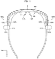
- the shield 200 when attached to the frame 100, may have a shape that forms a space S between the frame-front part 111 and the shield 200.
- the length of the shield 200 in the horizontal direction is made larger than the length between the right and left fixing members 120R and 120L of the frame main body 110.
- the shield 200 curves, so that the space S is formed between the frame-front part 111 and the shield 200.
- airflow between the face of the wearer and the shield 200 can be improved, so that it can be made harder for the shield 200 to be fogged up.
- the surface (outer surface) opposite to the side that faces the face of the wearer may be treated with water-repellent coating. If the body fluids and the like flown off from outside remain adhered to the shield 200, the field of view of the wearer is disturbed. Accordingly, by subjecting the outer surface of the shield 200 to the water-repellent coating treatment, the field of view of the shield 200 can be prevented from being disturbed by the splashed matter. Further, the shield 200 may be subjected to antiglare treatment for reducing the glare of illumination and the like.
- the face guard 1 is configured such that the shield 200 having a predetermined polarization property with respect to a three-dimensional image is attached to the frame 100. Accordingly, wearing the face guard 1, the wearer can be protected from adhesion of the splash coming from a patient, and the wearer can also view the three-dimensional image three-dimensionally, for example. By combining those functions, the case as in the past will not occur any more, in which a face guard is worn on top of polarized glasses for three-dimensional viewing of a three-dimensional image so that the polarization shifts, and it becomes possible for the wearer to view a normal three-dimensional image. Further, using the face guard for two-dimensional viewing, a worker such as a nurse who frequently moves around can avoid the 3D sickness caused by three-dimensional viewing, and can perform his/her tasks accurately and safely.
- a surgery system including the face guard 1 and a monitor that provides a three-dimensional image is used for a case of viewing endoscopic video three-dimensionally in endoscopic surgery, for example.
- a surgery system that provides a three-dimensional image can be employed in the case of performing dental treatment and ophthalmological treatment.
- the shield 200 of the face guard 1 described above includes a polarization area having a predetermined polarization property
- the present disclosure is not limited to such an example.
- an ordinary shield not including a polarization area may be attached to the frame 100 shown in FIGS. 2 to 8 .
- the shapes of fitting holes 235R and 235L of a shield 200C are different from each other, in a corresponding manner to the respective shapes of the fitting parts 127R and 127L of the fixing member 120 of the frame 100.
- the shield 200C is prevented from being attached inside-out.
- the shields 200A to 200C each cover at least an in-front-of-eyes part and a part of a side-of-face surface of the wearer
- the present disclosure is not limited to such examples.
- a shield 200D in which the vertical length is increased and which covers substantially entire in-front-of-face surface and a part of the side-of-face part.
- the shield 200D having such an external shape may be provided with the polarization area in the same manner as in FIGS. 9 and 10 , and may be configured such that a three-dimensional image can be viewed in a desired display state.
- the shapes of fitting holes 245R and 245L of the shield 200D are made different from each other, in a corresponding manner to the respective shapes of the fitting parts 127R and 127L of the fixing member 120 of the frame 100, and hence, the shield 200D is prevented from being attached inside-out.
- the shield 200 of the surgical face guard 1 is attachable to and detachable from the frame 100 and is a disposable member
- the present disclosure is not limited to such an example.
- the shield 200 may be fixed to the frame 100.
- the shield 200 is made of a material capable of being sterilized, or is processed so as to be capable of being sterilized.
- the face guard 1 is configured such that only one shield 200 is attached to the frame 100, but the present disclosure is not limited to such an example.
- multiple shields may be used by being piled up and attached to the frame 100 in that state.
- the face guard 1 may be configured such that a low-reflection shield is piled on a shield having a polarization property and the piled shields are attached to the frame 100.
- the frame 100 is a glasses-type frame in the present embodiment, the present disclosure is not limited to such an example.
- it may be worn on the forehead like a head band.
- present technology may also be configured as below.
Landscapes
- Health & Medical Sciences (AREA)
- Physics & Mathematics (AREA)
- Ophthalmology & Optometry (AREA)
- Engineering & Computer Science (AREA)
- Optics & Photonics (AREA)
- General Health & Medical Sciences (AREA)
- General Physics & Mathematics (AREA)
- Life Sciences & Earth Sciences (AREA)
- Public Health (AREA)
- Animal Behavior & Ethology (AREA)
- Heart & Thoracic Surgery (AREA)
- Biomedical Technology (AREA)
- Veterinary Medicine (AREA)
- Vascular Medicine (AREA)
- Surgery (AREA)
- Multimedia (AREA)
- Signal Processing (AREA)
- Nuclear Medicine, Radiotherapy & Molecular Imaging (AREA)
- Robotics (AREA)
- Human Computer Interaction (AREA)
- Medical Informatics (AREA)
- Molecular Biology (AREA)
- Helmets And Other Head Coverings (AREA)
- Endoscopes (AREA)
- Eyeglasses (AREA)
Abstract
Description
- The present disclosure relates to a surgical face guard, a surgical frame, a surgical polarization shield, and a surgery system.
- In recent years, on the front lines of health care, it has been put into practice that a video of an endoscope or the like is displayed as a three-dimensional image on a display device during surgery, so that a surgeon is provided with more easily-comprehensible video. The three-dimensional image can be shown, as described in
Patent Literature 1, for example, by using a head mounted display, which is a display device worn by a surgeon, and causing a shift to occur between a left-eye image signal and a right-eye image signal. Further, by letting a surgeon to wear polarized glasses having a polarization property of enabling three-dimensional viewing, the surgeon is allowed to perform three-dimensional viewing of a video displayed on a monitor or the like which is installed nearby. -
- Patent Literature 1:
JP H08-240784A - Patent Literature 2:
JP 2011-180265A - Medical workers such as surgeons and nurses wear face shields that cover their faces during surgery or the like, in order to prevent blood, body fluids, and the like flown off from a patient from adhering to the bodies of the medical workers, in particular, to faces where mucous membranes are exposed. A face shield is made of a transparent sheet-like material such as polyethylene terephthalate (PET), in order not to disturb the field of view of the wearer. When working in the state of wearing such a face shield, in the case of performing three-dimensional viewing of a three-dimensional image by using polarized glasses, the medical worker wears the face shield on top of the polarized glasses.
- However, if a face shield of related art is worn on top of the polarized glasses, the polarization is shifted, and it becomes not possible for the medical worker to visually recognize a normal three-dimensional image.
- Accordingly, the present disclosure proposes a surgical face guard, a surgical frame, a surgical polarization shield, and a surgery system, which are novel and improved, and with which a three-dimensional image can be used safely during medical treatment.
- According to the present disclosure, there is provided a surgical face guard, including a frame configured to be worn on a head of a medical worker, and a polarization shield configured to cover at least an in-front-of-eyes part and a part of a side-of-face surface of the medical worker, and have a predetermined polarization property with respect to a three-dimensional image.
- According to the present disclosure, there is provided a surgical frame, including a frame-front part configured to be placed in front of eyes of a medical worker, a frame-right-side part configured to extend from a right end of the frame-front part; and a frame-left-side part configured to extend from a left end of the frame-front part. The frame-right-side part or the frame-left-side part has a projection that protrudes toward an opposite side of a head of the medical worker.
- According to the present disclosure, there is provided a surgical polarization shield, including a polarization area configured to have a predetermined polarization property with respect to a three-dimensional image, a right-fitting hole configured to fit over a fitting part of a right-fixing member of a frame to be worn on a head of a medical worker, and a left-fitting hole configured to fit over a fitting part of a left-fixing member of the frame. A shape of the right-fitting hole is different from a shape of the left-fitting hole.
- According to the present disclosure, there is provided a surgery system, including a display device configured to display a three-dimensional image, and a surgical face guard including a frame configured to be worn on a head of a medical worker, and a polarization shield configured to cover at least an in-front-of-eyes part and a part of a side-of-face surface of the medical worker, and have a predetermined polarization property with respect to a three-dimensional image.
- As described above, according to the present disclosure, it becomes possible to use safely a three-dimensional image during medical treatment. Note that the effects described above are not necessarily limitative. With or in the place of the above effects, there may be achieved any one of the effects described in this specification or other effects that may be grasped from this specification.
-
- [
FIG. 1] FIG. 1 is a schematic perspective view showing a surgical face guard according to an embodiment of the present disclosure. - [
FIG. 2] FIG. 2 is a perspective view of a frame according to the embodiment. - [
FIG. 3] FIG. 3 is a plan view of the frame according to the embodiment. - [
FIG. 4] FIG. 4 is a bottom view of the frame according to the embodiment. - [
FIG. 5] FIG. 5 is a front view of the frame according to the embodiment. - [
FIG. 6] FIG. 6 is a back view of the frame according to the embodiment. - [
FIG. 7] FIG. 7 is a left-side view of the frame according to the embodiment. - [
FIG. 8] FIG. 8 is a right-side view of the frame according to the embodiment. - [
FIG. 9] FIG. 9 is a schematic plan view showing an example of a shield for three-dimensional viewing. - [
FIG. 10] FIG. 10 is a schematic plan view showing an example of a shield for two-dimensional viewing. - [
FIG. 11] FIG. 11 is a plan view showing a space for airflow, the space being formed between a frame and a shield. - [
FIG. 12] FIG. 12 is a schematic plan view showing an example of a shield that does not have a changing area. - [
FIG. 13] FIG. 13 is a schematic plan view showing an example of a shield that covers an entire face. - Hereinafter, preferred embodiments of the present disclosure will be described in detail with reference to the appended drawings. Note that, in this specification and the appended drawings, structural elements that have substantially the same function and structure are denoted with the same reference numerals, and repeated explanation of these structural elements is omitted.
- Note that the description will be given in the following order.
- 1. Schematic configuration of surgical face guard
- 2. Detailed configuration
- 2.1. Frame
- (1) Frame main body
- (2) Fixing member
- 2.2. Shield
- 2.1. Frame
- 3. Shield variations
- First, with reference to
FIG. 1 , a schematic configuration of asurgical face guard 1 according to an embodiment of the present disclosure will be described.FIG. 1 is a schematic perspective view showing thesurgical face guard 1 according to an embodiment of the present disclosure. - The surgical face guard (hereinafter, may also be referred to as "face guard") 1 according to the present embodiment is worn during surgery by a medical worker such as a surgeon, or a carer of the surgery including an endoscope operator or a nurse. As shown in
FIG. 1 , theface guard 1 includes aframe 100 and ashield 200 that is supported by theframe 100. Theframe 100 is a member for, in the state of supporting theshield 200, fixing theshield 200 to the wearer. For example, theframe 100 is formed in a glasses-type. When the glasses-type frame 100 is worn, theshield 200 is placed so as to cover from an in-front-of-eyes part that is the front of the eyes of the wearer to the temples of the wearer that are a part of a side-of-face part. - The
shield 200 is a transparent member that covers at least the in-front-of-eyes part and a part of the side-of-face part in order to prevent blood, body fluids, and the like flown off from a patient from adhering to the face. It is more preferred that theshield 200 have a shape that covers, not only the in-front-of-eyes part, but also up to a side-of-face surface, in order to prevent the splash coming from a side-direction of the face from entering the eyes. From a hygiene perspective, theshield 200 is made of a material capable of being sterilized or is disposable. Theface guard 1 according to the present embodiment is configured such that theshield 200 is provided so as to be attachable to and detachable from theframe 100. Accordingly, theshield 200 that is disposable can also be used. - Further, the
shield 200 according to the present embodiment has a polarization area. Theshield 200 according to the present embodiment is a polarization shield on which a polarization area having a predetermined polarization property is provided, in order to correctly view a three-dimensional image displayed on a monitor or the like in a predetermined display state. The polarization area of theshield 200 is, for example, a polarization area for three-dimensional viewing having a polarization property for allowing a three-dimensional image displayed on a monitor or the like to be viewed three-dimensionally, or a polarization area for two-dimensional viewing having a polarization property for allowing the three-dimensional image to be viewed two-dimensionally. The wearer can view the three-dimensional image in a desired display state by attaching theshield 200 having a corresponding polarization area to theframe 100 in accordance with the desired display state of the three-dimensional image. - That is, the
shield 200 according to the present embodiment has a function of preventing the splash coming from a patient from adhering to the wearer of theface guard 1, and also has a function as polarized glasses through which the wearer can view a three-dimensional image. Hereinafter, the configuration of theface guard 1 according to the present embodiment will be described in detail. - First, on the basis of
FIGS. 2 to 8 , theframe 100 of theface guard 1 according to the present embodiment will be described.FIG. 2 is a perspective view of theframe 100 according to the present embodiment.FIG. 3 is a plan view of theframe 100 according to the embodiment.FIG. 4 is a bottom view of theframe 100 according to the embodiment.FIG. 5 is a front view of theframe 100 according to the embodiment.FIG. 6 is a back view of theframe 100 according to the embodiment.FIG. 7 is a left-side view of theframe 100 according to the embodiment.FIG. 8 is a right-side view of theframe 100 according to the embodiment. - As shown in
FIG. 2 , theframe 100 according to the present embodiment includes a framemain body 110 of a glasses-type, and fixing members 120 for fixing theshield 200 to the framemain body 110. - The frame
main body 110 includes a frame-front part 111 which is placed in front of the eyes of the wearer of theface guard 1, andtemple parts front part 111 and rest on the right and left ears, respectively, of the wearer. The frame-front part 111 is provided over the upper side of the eyes of the wearer, so that the field of view of the wearer can be prevented from being disturbed. At the center part of the frame-front part 111, there are providednose pad parts frame 100 to the head. - The
temple parts main body 110. For example, thetemple parts main body 110 via a hinge and to be foldable, or may be formed integrally with the framemain body 110. On thetemple parts members shield 200. On thetemple parts holes 114R and 114L that fit overfitting parts members - On the
temple parts main body 110, the fixingmembers shield 200 to the framemain body 110. The fixingmembers shield 200 to be fixed to the framemain body 110 are fixed, respectively. For example, the fixingmembers face guard 1 are positioned. The fixingmembers attachment parts parts parts fitting parts - The
attachment parts members temple parts main body 110, respectively. Theattachment parts temple parts temple parts attachment parts attachment parts temple parts - The holding
parts face guard 1, respectively, in a state in which the fixingmembers temple parts face guard 1 sometimes gets another worker to attach or detach theface guard 1. In this case, in order to make it easy for the other worker to attach or detach theface guard 1 to or from the wearer, the framemain body 110 is provided with the holdingparts parts main body 110, to attach or detach theface guard 1. - The shapes of the holding
parts parts FIG. 2 , the holdingparts parts parts parts temple parts - The fixing
parts shield 200 to theframe 100. For example, as shown inFIG. 2 , the fixingparts attachment parts temple parts front part 111. The fixingparts temple parts attachment parts - The fixing
parts fitting parts temple parts fitting parts holes 114R and 114L of thetemple parts reference numerals FIG. 9 ) of theshield 200 to be fixed to theframe 100, respectively. The fixing holes 114R and 114L and the fitting holes are formed in a corresponding manner to thefitting parts shield 200 is sandwiched between thetemple part 113R and the fixingpart 125R and between thetemple part 113L and the fixingpart 125L, thefitting parts parts holes 114R and 114L of thetemple parts shield 200 is fixed to theframe 100. - Here, as shown in
FIG. 3 , the shape of the right-fittingpart 127R is different from the shape of the left-fitting part 127L. That is, the right-fitting hole of theshield 200 and the fixing hole 114R of thetemple part 113R on the right side are formed in a corresponding manner to the shape of the right-fittingpart 127R. In the same manner, the left-fitting hole of theshield 200 and the fixinghole 114L of thetemple part 113L on the left side are formed in a corresponding manner to the shape of the left-fitting part 127L. Theshield 200 to be fixed to theframe 100 has different polarization properties between an area corresponding to the right eye and an area corresponding to the left eye, and if theshield 200 is fixed to theframe 100 inside out, a correct image cannot be provided to the wearer. Accordingly, by making the shape of the right-fittingpart 127R different from the shape of the left-fitting part 127L, a correct side to which theshield 200 is to be attached can be shown to the wearer (or the other worker), and theshield 200 can be attached in the state in which the correct side is facing the correct way. - In the present embodiment, the right-fitting
part 127R is a projection having a horizontally oriented shape, and the left-fitting part 127L is a projection having a vertically oriented shape. Note that the shapes of the right-fittingpart 127R and the left-fitting part 127L are not limited to such an example, and the shape of the right-fittingpart 127R and the shape of the left-fitting part 127L may be any as long as the shapes are different from each other. Note that, in the present disclosure, when it is attempted that theshield 200 is attached to theframe 100 correctly, the right fitting hole and the left fitting hole of theshield 200 may be provided in such a way only as to fit over the correspondingfitting parts members fitting parts part 127R and the shape of the left-fitting part 127L are congruent but are differently oriented is also included in the one in which the shapes of the right and leftfitting parts - The
frame 100 according to the present embodiment described above is made of a material that is resistant to sterilization. For example, theframe 100 is made of polycarbonate (PC) or elastomer resin. Alternatively, the surface of theframe 100 may be processed to be resistant to sterilization. In this way, theframe 100 can be used repeatedly by performing sterilization. - Next, with reference to
FIGS. 9 and 10 , theshield 200 according to the present embodiment will be described.FIG. 9 is a schematic plan view showing an example of ashield 200A for three-dimensional viewing.FIG. 10 is a schematic plan view showing an example of ashield 200B for two-dimensional viewing. - The
shield 200 according to the present embodiment is a transparent protective member that covers at least an in-front-of-eyes part and a part of a side-of-face part of the wearer of theface guard 1, and is a polarization shield that has a polarization property. Examples of theshield 200 according to the present embodiment include theshield 200A for three-dimensional viewing and theshield 200B for two-dimensional viewing. - As shown in
FIGS. 9 and 10 , theshield 200A for three-dimensional viewing and theshield 200B for two-dimensional viewing may be formed to have the same external shape. With reference toFIG. 9 , the shape of theshield 200A for three-dimensional viewing will be described. Theshield 200A for three-dimensional viewing is made of one sheet-like material. Theshield 200A has a size enough to cover at least an in-front-of-eyes part and a part of a side-of-face part of the wearer, and, as shown inFIG. 9 , anotch 211 for letting the nose of the wearer through may be provided at the bottom center in the horizontal direction of a part that covers the in-front-of-eyes part. - In the both end parts in the horizontal direction of the
shield 200A, there are providedfitting holes shield 200A to theframe 100. Thefitting holes fitting parts members frame 100. Accordingly, the shape of the right-fittinghole 215R is different from the shape of the left-fitting hole 215L. The wearer (or another worker) orients the position of theshield 200 so as to be fit to the shapes of thefitting parts members frame 100, and thus, the back and front of theshield 200 with respect to theframe 100 can be set correctly. - Further, in the both end parts in the horizontal direction of the
shield 200A, there may be providedengaging parts attachment parts members shield 200 is hooked to theattachment parts shield 200 to slip off from theframe 110. - The
shield 200A is made of a transparent sheet-like material such as polycarbonate (PC) or triacetyl cellulose (TAC), in order not to disturb the field of view of the wearer. Theshield 200A for three-dimensional viewing according to the present embodiment includes apolarization area 210 having a polarization property of enabling three-dimensional viewing of a three-dimensional image displayed on an external monitor. Thepolarization area 210 includes a right-eye polarization area 210R corresponding to the right eye of the wearer of theface guard 1 and a left-eye polarization area 210L corresponding to the left eye of the wearer of theface guard 1. Theshield 200A for three-dimensional viewing according to the present embodiment is made of a single film which is seamless between the right-eye polarization area 210R and the left-eye polarization area 210L. - The
shield 200A for three-dimensional viewing configures theface guard 1 like the one shown inFIG. 1 , by being attached to theframe 100. Wearing theface guard 1 including theshield 200A for three-dimensional viewing, the wearer can be protected from adhesion of the splash coming from a patient and can also view the three-dimensional image. By combining those functions, the case as in the past will not occur any more, in which a face guard is worn on top of polarized glasses for three-dimensional viewing of a three-dimensional image so that the polarization shifts, and it becomes possible for the wearer to view a normal three-dimensional image. - On the other hand, in the case of viewing the three-dimensional image not as a three-dimensional image, but as a two-dimensional image, there may be used a
face guard 1 in which theshield 200B for two-dimensional viewing is attached to theframe 100, theshield 200B for two-dimensional viewing having a polarization property of enabling two-dimensional viewing of a three-dimensional image. Theshield 200B for two-dimensional viewing includes apolarization area 220 having a right-eye polarization area 220R corresponding to the right eye of the wearer of theface guard 1 and a left-eye polarization area 220L corresponding to the left eye of the wearer of theface guard 1. Viewing the three-dimensional image through thepolarization area 220, the three-dimensional image can be viewed not as a three-dimensional image, but as a two-dimensional image. In particular, a worker such as a nurse who frequently moves around may suffer from so-called 3D sickness through viewing of the three-dimensional image. In order to prevent the 3D sickness, it is desirable that the worker view the three-dimensional image as a two-dimensional image. In this way, the worker can perform his/her tasks accurately and safely without suffering from the 3D sickness. - As shown in
FIG. 10 , the external shape of theshield 200B for two-dimensional viewing may be the same as the external shape of theshield 200A for three-dimensional viewing. In this case, although the external shape of theshield 200A for three-dimensional viewing is the same as the external shape of theshield 200B for two-dimensional viewing, the polarization property of theshield 200A for three-dimensional viewing is different from the polarization property of theshield 200B for two-dimensional viewing. However, it is difficult to distinguish the difference between thepolarization areas shield 200A for three-dimensional viewing and theshield 200B for two-dimensional viewing according to the present embodiment are provided with identification marks 217 and 227, respectively, which show the respective polarization properties. - The identification marks 217 and 227 are printed on the
shields FIG. 9 , on theshield 200A for three-dimensional viewing, the letters "3D" are printed as theidentification mark 217 above the left-fitting hole 215L. Further, as shown inFIG. 10 , on theshield 200B for two-dimensional viewing, the letters "2D" are printed as theidentification mark 227 above the left-fitting hole 225L. By providing the identification marks 217 and 227 in this way, ashield 200 having a desired polarization property can be attached to theframe 100 without making an error. - Note that, as shown in
FIGS. 9 and 10 , the identification marks 217 and 227 may be printed on therespective shields 200 themselves, or, an identification mark may be provided on a protective film (not shown) which is stuck on the shield for the protecting purpose before use of theshield 200. In the case where the identification marks 217 and 227 are provided on therespective shields 200 themselves, the identification marks 217 and 227 may be provided at positions at which it is difficult to be included in the field of view of the wearer, in order not to disturb the field of view of the user when used as theface guard 1. On the other hand, in the case where an identification mark is provided on a protective film of theshield 200, since the protective film is peeled from theshield 200 at the point of use, the protective film does not disturb the field of view of the wearer when used. - Further, the identification mark may be the letters such as "3D" or "2D" as shown in
FIGS. 9 and 10 , and may also be symbols or the like that differ in accordance with polarization properties. Further, by fixing the position at which the identification mark is provided, the identification of the back and front of theshield 200 can be shown more reliably. For example, as shown inFIGS. 9 and 10 , by providing the identification marks 217 and 227 above the left-fitting hole 215L at all times, the back and front of theshields 200 can be set correctly when theshields 200 are provided such that the identification marks 217 and 227 are placed at the left sides with respect to the respective frames 100. - In addition, to each of those
shields 200, the surface (inner surface) at the side that faces the face of the wearer may be treated with antifog coating that prevents fogging. It is likely that vapor stays between the face of the wearer and theshield 200 due to the respiration and the like. When theshield 200 becomes foggy due to the vapor, the field of view of the wearer is blocked. Accordingly, by treating the surface (inner surface) at the side that faces the face of the wearer with antifog coating, the wearer can safely perform medical treatment. - Further, as shown in
FIG. 11 , when attached to theframe 100, theshield 200 according to the present embodiment may have a shape that forms a space S between the frame-front part 111 and theshield 200. For example, the length of theshield 200 in the horizontal direction is made larger than the length between the right and left fixingmembers main body 110. In this way, when the both end parts are fixed by the fixingmembers shield 200 curves, so that the space S is formed between the frame-front part 111 and theshield 200. With this space S, airflow between the face of the wearer and theshield 200 can be improved, so that it can be made harder for theshield 200 to be fogged up. - Still further, to the
shield 200, the surface (outer surface) opposite to the side that faces the face of the wearer may be treated with water-repellent coating. If the body fluids and the like flown off from outside remain adhered to theshield 200, the field of view of the wearer is disturbed. Accordingly, by subjecting the outer surface of theshield 200 to the water-repellent coating treatment, the field of view of theshield 200 can be prevented from being disturbed by the splashed matter. Further, theshield 200 may be subjected to antiglare treatment for reducing the glare of illumination and the like. - Heretofore, the
face guard 1 according to the present embodiment has been described. In the present embodiment, theface guard 1 is configured such that theshield 200 having a predetermined polarization property with respect to a three-dimensional image is attached to theframe 100. Accordingly, wearing theface guard 1, the wearer can be protected from adhesion of the splash coming from a patient, and the wearer can also view the three-dimensional image three-dimensionally, for example. By combining those functions, the case as in the past will not occur any more, in which a face guard is worn on top of polarized glasses for three-dimensional viewing of a three-dimensional image so that the polarization shifts, and it becomes possible for the wearer to view a normal three-dimensional image. Further, using the face guard for two-dimensional viewing, a worker such as a nurse who frequently moves around can avoid the 3D sickness caused by three-dimensional viewing, and can perform his/her tasks accurately and safely. - A surgery system including the
face guard 1 and a monitor that provides a three-dimensional image is used for a case of viewing endoscopic video three-dimensionally in endoscopic surgery, for example. In addition, such a surgery system that provides a three-dimensional image can be employed in the case of performing dental treatment and ophthalmological treatment. - Although the
shield 200 of theface guard 1 described above includes a polarization area having a predetermined polarization property, the present disclosure is not limited to such an example. For example, to theframe 100 shown inFIGS. 2 to 8 , an ordinary shield not including a polarization area may be attached. Also in this case, as shown inFIG. 12 , the shapes offitting holes shield 200C are different from each other, in a corresponding manner to the respective shapes of thefitting parts frame 100. - As described above, since the inner side of the
shield 200 is treated with antifog coating and the outer side of theshield 200 is treated with water-repellent coating, it is necessary that the back and front of theshield 200 is set correctly when theshield 200 is attached to theframe 100. Accordingly, by making the shapes of thefitting holes shield 200C different from each other, theshield 200C is prevented from being attached inside-out. - Further, although it has been described in the above examples that the
shields 200A to 200C each cover at least an in-front-of-eyes part and a part of a side-of-face surface of the wearer, the present disclosure is not limited to such examples. For example, as shown inFIG. 13 , there may be provided ashield 200D in which the vertical length is increased and which covers substantially entire in-front-of-face surface and a part of the side-of-face part. Using theshield 200D that covers a wide area of the face, not only the eyes but also other parts where mucous membranes are exposed, such as the nose and the mouth, can also be protected. - Also the
shield 200D having such an external shape may be provided with the polarization area in the same manner as inFIGS. 9 and 10 , and may be configured such that a three-dimensional image can be viewed in a desired display state. In addition, in the same manner as in the above-mentioned examples, the shapes offitting holes shield 200D are made different from each other, in a corresponding manner to the respective shapes of thefitting parts frame 100, and hence, theshield 200D is prevented from being attached inside-out. - The preferred embodiment(s) of the present disclosure has/have been described above with reference to the accompanying drawings, whilst the present disclosure is not limited to the above examples. A person skilled in the art may find various alterations and modifications within the scope of the appended claims, and it should be understood that they will naturally come under the technical scope of the present disclosure.
- For example, although it has been described in the above embodiment that the
shield 200 of thesurgical face guard 1 is attachable to and detachable from theframe 100 and is a disposable member, the present disclosure is not limited to such an example. For example, theshield 200 may be fixed to theframe 100. In this case, theshield 200 is made of a material capable of being sterilized, or is processed so as to be capable of being sterilized. - Further, in the above-mentioned embodiment, the
face guard 1 is configured such that only oneshield 200 is attached to theframe 100, but the present disclosure is not limited to such an example. For example, multiple shields may be used by being piled up and attached to theframe 100 in that state. For example, theface guard 1 may be configured such that a low-reflection shield is piled on a shield having a polarization property and the piled shields are attached to theframe 100. - In addition, although the
frame 100 is a glasses-type frame in the present embodiment, the present disclosure is not limited to such an example. For example, it may be worn on the forehead like a head band. - Further, the effects described in this specification are merely illustrative or exemplified effects, and are not limitative. That is, with or in the place of the above effects, the technology according to the present disclosure may achieve other effects that are clear to those skilled in the art based on the description of this specification.
- Additionally, the present technology may also be configured as below.
- (1) A surgical face guard, including:
- a frame configured to be worn on a head of a medical worker; and
- a polarization shield configured to cover at least an in-front-of-eyes part and a part of a side-of-face surface of the medical worker, and have a predetermined polarization property with respect to a three-dimensional image.
- (2) The surgical face guard according to (1), wherein
the polarization shield is provided so as to be attachable to and detachable from the frame, and
the frame includes a right-fixing member that fixes the polarization shield at a right-side part of the frame and a left-fixing member that fixes the polarization shield at a left-side part of the frame. - (3) The surgical face guard according to (2), wherein
the polarization shield includes a right-fitting hole that fits over a fitting part of the right-fixing member and a left-fitting hole that fits over a fitting part of the left-fixing member, and
a shape of the right-fitting hole is different from a shape of the left-fitting hole. - (4) The surgical face guard according to any one of (1) to (3), wherein
the polarization shield is a shield for three-dimensional viewing that has a polarization property of enabling three-dimensional viewing of a three-dimensional image. - (5) The surgical face guard according to any one of (1) to (3), wherein
the polarization shield is a shield for two-dimensional viewing that has a polarization property of enabling two-dimensional viewing of a three-dimensional image. - (6) The surgical face guard according to any one of (1) to (5), wherein
the polarization shield is provided with an identification mark indicating a polarization property. - (7) The surgical face guard according to any one of (1) to (6), wherein
an inner surface of the polarization shield is treated with antifog coating that prevents fogging, the inner surface facing a face of the medical worker. - (8) The surgical face guard according to any one of (1) to (7), wherein
an outer surface of the polarization shield is treated with water-repellent coating, the outer surface being an opposite side of an inner surface of the polarization shield, the inner surface facing a face of the medical worker. - (9) The surgical face guard according to any one of (1) to (8), further including
another shield configured to be superimposed on the polarization shield. - (10) The surgical face guard according to any one of (1) to (9), wherein
the frame has a projection that protrudes from a right-side part or a left-side part toward an opposite side of the head of the medical worker. - (11) The surgical face guard according to any one of (1) to (10), wherein
the frame is made of a material that is resistant to sterilization or the frame is processed to be resistant to sterilization. - (12) The surgical face guard according to any one of (1) to (11), wherein
the polarization shield covers a substantially entire part of the in-front-of-face surface of the medical worker. - (13) The surgical face guard according to (1) to (12), wherein
the three-dimensional image is an endoscopic image related to a surgical site of a patient. - (14) A surgical frame, including:
- a frame-front part configured to be placed in front of eyes of a medical worker;
- a frame-right-side part configured to extend from a right end of the frame-front part; and
- a frame-left-side part configured to extend from a left end of the frame-front part,
- (15) The surgical frame according to (14), wherein
the frame-right-side part includes a right-fitting part of a right-fixing member that fixes a polarization shield having a predetermined polarization property with respect to a three-dimensional image,
the frame-left-side part includes a left-fitting part of a left-fixing member that fixes the polarization shield, and a shape of the right-fitting part is different from a shape of the left-fitting part. - (16) A surgical polarization shield, including:
- a polarization area configured to have a predetermined polarization property with respect to a three-dimensional image;
- a right-fitting hole configured to fit over a fitting part of a right-fixing member of a frame to be worn on a head of a medical worker; and
- a left-fitting hole configured to fit over a fitting part of a left-fixing member of the frame,
- (17) A surgery system, including:
- a display device configured to display a three-dimensional image; and
- a surgical face guard including
- a frame configured to be worn on a head of a medical worker, and
- a polarization shield configured to cover at least an in-front-of-eyes part and a part of a side-of-face surface of the medical worker, and have a predetermined polarization property with respect to a three-dimensional image.
-
- 1
- surgical face guard
- 100
- frame
- 110
- frame main body
- 111
- frame-front part
- 112R, 112L
- nose pad part
- 113R, 113L
- temple part
- 114R, 114L
- fixing hole
- 120R, 120L
- fixing member
- 121R, 121L
- attachment part
- 123R, 123L
- holding part
- 125R, 125L
- fixing part
- 127L
- left-fitting part
- 127R
- right-fitting part
- 200
- shield
- 210, 220
- polarization area
- 210L, 220L
- left-eye polarization area
- 210R, 220R
- right-eye polarization area
- 211
- notch
- 213R, 213L
- engaging part
- 215L
- left-fitting hole
- 215R
- right-fitting hole
- 217, 227
- identification mark
Claims (17)
- A surgical face guard, comprising:a frame configured to be worn on a head of a medical worker; anda polarization shield configured to cover at least an in-front-of-eyes part and a part of a side-of-face surface of the medical worker, and have a predetermined polarization property with respect to a three-dimensional image.
- The surgical face guard according to claim 1, wherein
the polarization shield is provided so as to be attachable to and detachable from the frame, and the frame includes a right-fixing member that fixes the polarization shield at a right-side part of the frame and a left-fixing member that fixes the polarization shield at a left-side part of the frame. - The surgical face guard according to claim 2, wherein
the polarization shield includes a right-fitting hole that fits over a fitting part of the right-fixing member and a left-fitting hole that fits over a fitting part of the left-fixing member, and
a shape of the right-fitting hole is different from a shape of the left-fitting hole. - The surgical face guard according to claim 1, wherein
the polarization shield is a shield for three-dimensional viewing that has a polarization property of enabling three-dimensional viewing of a three-dimensional image. - The surgical face guard according to claim 1, wherein
the polarization shield is a shield for two-dimensional viewing that has a polarization property of enabling two-dimensional viewing of a three-dimensional image. - The surgical face guard according to claim 1, wherein
the polarization shield is provided with an identification mark indicating a polarization property. - The surgical face guard according to claim 1, wherein
an inner surface of the polarization shield is treated with antifog coating that prevents fogging, the inner surface facing a face of the medical worker. - The surgical face guard according to claim 1, wherein
an outer surface of the polarization shield is treated with water-repellent coating, the outer surface being an opposite side of an inner surface of the polarization shield, the inner surface facing a face of the medical worker. - The surgical face guard according to claim 1, further comprising
another shield configured to be superimposed on the polarization shield. - The surgical face guard according to claim 1, wherein
the frame has a projection that protrudes from a right-side part or a left-side part toward an opposite side of the head of the medical worker. - The surgical face guard according to claim 1, wherein
the frame is made of a material that is resistant to sterilization or the frame is processed to be resistant to sterilization. - The surgical face guard according to claim 1, wherein
the polarization shield covers a substantially entire part of the in-front-of-face surface of the medical worker. - The surgical face guard according to claim 1, wherein
the three-dimensional image is an endoscopic image related to a surgical site of a patient. - A surgical frame, comprising:a frame-front part configured to be placed in front of eyes of a medical worker;a frame-right-side part configured to extend from a right end of the frame-front part; anda frame-left-side part configured to extend from a left end of the frame-front part,wherein the frame-right-side part or the frame-left-side part has a projection that protrudes toward an opposite side of a head of the medical worker.
- The surgical frame according to claim 14, wherein
the frame-right-side part includes a right-fitting part of a right-fixing member that fixes a polarization shield having a predetermined polarization property with respect to a three-dimensional image,
the frame-left-side part includes a left-fitting part of a left-fixing member that fixes the polarization shield, and
a shape of the right-fitting part is different from a shape of the left-fitting part. - A surgical polarization shield, comprising:a polarization area configured to have a predetermined polarization property with respect to a three-dimensional image;a right-fitting hole configured to fit over a fitting part of a right-fixing member of a frame to be worn on a head of a medical worker; anda left-fitting hole configured to fit over a fitting part of a left-fixing member of the frame,wherein a shape of the right-fitting hole is different from a shape of the left-fitting hole.
- A surgery system, comprising:a display device configured to display a three-dimensional image; anda surgical face guard includinga frame configured to be worn on a head of a medical worker, anda polarization shield configured to cover at least an in-front-of-eyes part and a part of a side-of-face surface of the medical worker, and have a predetermined polarization property with respect to a three-dimensional image.
Applications Claiming Priority (2)
| Application Number | Priority Date | Filing Date | Title |
|---|---|---|---|
| JP2015022159 | 2015-02-06 | ||
| PCT/JP2016/050909 WO2016125551A1 (en) | 2015-02-06 | 2016-01-14 | Surgical face guard, surgical frame, surgical polarizing shield, and surgical system |
Publications (2)
| Publication Number | Publication Date |
|---|---|
| EP3111788A1 true EP3111788A1 (en) | 2017-01-04 |
| EP3111788A4 EP3111788A4 (en) | 2018-01-10 |
Family
ID=56563902
Family Applications (1)
| Application Number | Title | Priority Date | Filing Date |
|---|---|---|---|
| EP16746382.7A Ceased EP3111788A4 (en) | 2015-02-06 | 2016-01-14 | Surgical face guard, surgical frame, surgical polarizing shield, and surgical system |
Country Status (5)
| Country | Link |
|---|---|
| US (1) | US10702345B2 (en) |
| EP (1) | EP3111788A4 (en) |
| JP (1) | JP6747296B2 (en) |
| CN (1) | CN106132224B (en) |
| WO (1) | WO2016125551A1 (en) |
Families Citing this family (18)
| Publication number | Priority date | Publication date | Assignee | Title |
|---|---|---|---|---|
| US11589633B2 (en) * | 2019-11-13 | 2023-02-28 | O&M Halyard, Inc. | Multi-layer visor system for surgical hood |
| JP7132574B2 (en) * | 2020-02-10 | 2022-09-07 | 株式会社ドクター中松創研 | Supermen (M.E.N.) |
| JP6821286B1 (en) * | 2020-06-12 | 2021-01-27 | 株式会社ファーストリテイリング | mask |
| GB2596116A (en) * | 2020-06-18 | 2021-12-22 | Conker Living Ltd | A clip for a face shield |
| US10881157B1 (en) * | 2020-07-08 | 2021-01-05 | Mawco Tech Inc. | Temperature-reading face shield |
| CN111887517A (en) * | 2020-07-22 | 2020-11-06 | 东莞宏胜光学眼镜有限公司 | Clamping type mask |
| JP2022047477A (en) * | 2020-09-11 | 2022-03-24 | 大日本印刷株式会社 | Transparent laminated film, transparent laminated film with protection film, and face shield |
| US11914232B2 (en) | 2020-10-09 | 2024-02-27 | Deroyal Industries, Inc. | Eye shields with selectively releasable snap-fit assembly |
| US11911317B2 (en) | 2020-10-09 | 2024-02-27 | Deroyal Industries, Inc. | Stackable eye shields with selectively releasable snap-fit assembly |
| CN112168354B (en) * | 2020-10-14 | 2021-07-16 | 北京科迈启元科技有限公司 | Waterproof and lightweight surgical robot actuator and surgical robot system |
| JPWO2022118693A1 (en) * | 2020-12-01 | 2022-06-09 | ||
| USD980312S1 (en) | 2021-03-31 | 2023-03-07 | Deroyal Industries, Inc. | Eye shield |
| USD1008348S1 (en) | 2021-03-31 | 2023-12-19 | Deroyal Industries, Inc. | Eye shield |
| USD1030850S1 (en) | 2021-09-17 | 2024-06-11 | Deroyal Industries, Inc. | Eye shield |
| USD1034773S1 (en) | 2021-09-17 | 2024-07-09 | Deroyal Industries, Inc. | Eye shield |
| USD983867S1 (en) | 2021-09-17 | 2023-04-18 | Deroyal Industries, Inc. | Eye shield |
| US12304704B2 (en) * | 2021-09-17 | 2025-05-20 | Deroyal Industries, Inc. | Stackable eye shields |
| USD989852S1 (en) | 2021-09-17 | 2023-06-20 | Deroyal Industries, Inc. | Eye shield |
Family Cites Families (25)
| Publication number | Priority date | Publication date | Assignee | Title |
|---|---|---|---|---|
| JPH04104219A (en) * | 1990-08-24 | 1992-04-06 | Hoya Corp | goggles |
| JPH08240784A (en) | 1995-03-03 | 1996-09-17 | Olympus Optical Co Ltd | Head mounted type video display device |
| JPH09224756A (en) | 1996-02-20 | 1997-09-02 | Inax Corp | Cabinet |
| US5692522A (en) * | 1996-06-06 | 1997-12-02 | Op-D-Op, Inc. | Face shield apparatus |
| US7272860B2 (en) | 2004-10-18 | 2007-09-25 | Anthony Vega | Protective face shield adjustment system |
| EP1865799B1 (en) | 2005-03-24 | 2010-06-09 | Stryker Corporation | Personal protection system |
| JP4333923B2 (en) | 2005-12-16 | 2009-09-16 | 株式会社バンダイナムコゲームス | Rotating display device |
| ES2569880T3 (en) * | 2006-12-15 | 2016-05-12 | Resmed Ltd. | Administration of respiratory therapy |
| US8605008B1 (en) * | 2007-05-04 | 2013-12-10 | Apple Inc. | Head-mounted display |
| WO2012078197A1 (en) * | 2010-01-22 | 2012-06-14 | Oakley, Inc. | Eyewear with three-dimensional viewing capability |
| JP5550944B2 (en) | 2010-02-26 | 2014-07-16 | 山本光学株式会社 | Single-lens polarized glasses |
| US20110228184A1 (en) * | 2010-03-12 | 2011-09-22 | Kennedy John E | Protective eyewear incorporating 3d lenses for use with a 3d visualization system |
| AU2011227042B2 (en) * | 2010-03-19 | 2014-03-06 | Oakley, Inc. | Goggle |
| JP2011209659A (en) | 2010-03-30 | 2011-10-20 | Fujifilm Corp | Glasses for three-dimensional vision |
| JP2012010217A (en) * | 2010-06-28 | 2012-01-12 | Nikon Corp | Eyeglasses and display system |
| US8918831B2 (en) * | 2010-07-06 | 2014-12-23 | At&T Intellectual Property I, Lp | Method and apparatus for managing a presentation of media content |
| JP2012088503A (en) | 2010-10-19 | 2012-05-10 | Jvc Kenwood Corp | Stereoscopic spectacle |
| JP2016012391A (en) | 2012-10-29 | 2016-01-21 | 三洋電機株式会社 | Power storage device |
| EP2914228B1 (en) * | 2012-11-01 | 2017-12-13 | Abominable Labs, LLC | Goggle with battery pods |
| WO2014113791A2 (en) * | 2013-01-21 | 2014-07-24 | Tidi Products, Llc | Modular eye protection |
| JP2014199301A (en) * | 2013-03-29 | 2014-10-23 | 株式会社有沢製作所 | Member for spectacles, spectacles and method of manufacturing member for spectacles |
| US9532617B2 (en) * | 2014-02-21 | 2017-01-03 | Tidi Products, Llc | Disposable face shield |
| CN104116496B (en) * | 2014-07-11 | 2016-06-22 | 深圳先进技术研究院 | Medical three dimension vein blood vessel augmented reality device and method |
| JP3194865U (en) * | 2014-10-01 | 2014-12-11 | 株式会社 エリカ オプチカル | Face guard frame |
| WO2016064731A1 (en) * | 2014-10-23 | 2016-04-28 | Tidi Products, Llc | System and method for protective eyewear |
-
2016
- 2016-01-14 US US15/128,268 patent/US10702345B2/en active Active
- 2016-01-14 CN CN201680000939.5A patent/CN106132224B/en active Active
- 2016-01-14 JP JP2016552359A patent/JP6747296B2/en active Active
- 2016-01-14 EP EP16746382.7A patent/EP3111788A4/en not_active Ceased
- 2016-01-14 WO PCT/JP2016/050909 patent/WO2016125551A1/en not_active Ceased
Also Published As
| Publication number | Publication date |
|---|---|
| CN106132224A (en) | 2016-11-16 |
| US20170119479A1 (en) | 2017-05-04 |
| CN106132224B (en) | 2020-11-06 |
| US10702345B2 (en) | 2020-07-07 |
| WO2016125551A1 (en) | 2016-08-11 |
| JP6747296B2 (en) | 2020-08-26 |
| EP3111788A4 (en) | 2018-01-10 |
| JPWO2016125551A1 (en) | 2017-11-16 |
Similar Documents
| Publication | Publication Date | Title |
|---|---|---|
| EP3111788A1 (en) | Surgical face guard, surgical frame, surgical polarizing shield, and surgical system | |
| US20240156641A1 (en) | Surgical robotic instrument shield | |
| CN103323949B (en) | Head mounted display | |
| US20120013984A1 (en) | Jacket and head-mounted optical system | |
| EP3139779B1 (en) | Protective apparel system with impervious protection | |
| JP2017032877A (en) | Eye shield and attachment device | |
| WO2014189364A1 (en) | Disposable surgical face shield | |
| EP3297590A1 (en) | Protective mask | |
| CN104905427B (en) | Operation disposable head and face protective cover | |
| IT201800009135A1 (en) | VISOR FOR PROTECTION FROM IONIZING RADIATION FOR USE IN SURGICAL INTERVENTIONS | |
| KR20220170603A (en) | Protective hood for surgery | |
| US20240024161A1 (en) | Medical face guard, medical face shield, medical frame, and medical face guard manufacturing method | |
| JP2013533058A (en) | Protective glasses | |
| JPH08248346A (en) | Head mounting type video display device | |
| CN203884732U (en) | Surgical disposable head and face protective mask | |
| CN217644655U (en) | Operation cap with mask for surgeon | |
| CN104977730A (en) | Medical protective glasses | |
| KR20140003060U (en) | Face mask with elastic band | |
| JP6171078B1 (en) | Eye guard frame and eye guard | |
| CN213552874U (en) | Medical protection device for bronchoscopy | |
| KR20190143034A (en) | Device for protecting face of patient | |
| US20230138060A1 (en) | Device for protecting at least one part of the face | |
| JP2021169675A (en) | Face guard | |
| JP2014074790A (en) | Three-dimensional spectacle with sterilization part |
Legal Events
| Date | Code | Title | Description |
|---|---|---|---|
| PUAI | Public reference made under article 153(3) epc to a published international application that has entered the european phase |
Free format text: ORIGINAL CODE: 0009012 |
|
| STAA | Information on the status of an ep patent application or granted ep patent |
Free format text: STATUS: REQUEST FOR EXAMINATION WAS MADE |
|
| 17P | Request for examination filed |
Effective date: 20160929 |
|
| AK | Designated contracting states |
Kind code of ref document: A1 Designated state(s): AL AT BE BG CH CY CZ DE DK EE ES FI FR GB GR HR HU IE IS IT LI LT LU LV MC MK MT NL NO PL PT RO RS SE SI SK SM TR |
|
| AX | Request for extension of the european patent |
Extension state: BA ME |
|
| RIC1 | Information provided on ipc code assigned before grant |
Ipc: A61B 90/00 20160101ALI20170906BHEP Ipc: G02C 9/00 20060101ALI20170906BHEP Ipc: A41D 13/11 20060101AFI20170906BHEP Ipc: G02C 7/12 20060101ALI20170906BHEP Ipc: G02B 27/02 20060101ALI20170906BHEP |
|
| A4 | Supplementary search report drawn up and despatched |
Effective date: 20171213 |
|
| RIC1 | Information provided on ipc code assigned before grant |
Ipc: G02C 7/12 20060101ALI20171207BHEP Ipc: A61B 90/00 20160101ALI20171207BHEP Ipc: G02C 9/00 20060101ALI20171207BHEP Ipc: G02B 27/02 20060101ALI20171207BHEP Ipc: A41D 13/11 20060101AFI20171207BHEP |
|
| DAV | Request for validation of the european patent (deleted) | ||
| DAX | Request for extension of the european patent (deleted) | ||
| STAA | Information on the status of an ep patent application or granted ep patent |
Free format text: STATUS: EXAMINATION IS IN PROGRESS |
|
| 17Q | First examination report despatched |
Effective date: 20180920 |
|
| RAP3 | Party data changed (applicant data changed or rights of an application transferred) |
Owner name: SONY GROUP CORPORATION |
|
| REG | Reference to a national code |
Ref country code: DE Ref legal event code: R003 |
|
| STAA | Information on the status of an ep patent application or granted ep patent |
Free format text: STATUS: THE APPLICATION HAS BEEN REFUSED |
|
| 18R | Application refused |
Effective date: 20230212 |