EP3111497B1 - Molding process for making fuel cell components - Google Patents
Molding process for making fuel cell components Download PDFInfo
- Publication number
- EP3111497B1 EP3111497B1 EP14884192.7A EP14884192A EP3111497B1 EP 3111497 B1 EP3111497 B1 EP 3111497B1 EP 14884192 A EP14884192 A EP 14884192A EP 3111497 B1 EP3111497 B1 EP 3111497B1
- Authority
- EP
- European Patent Office
- Prior art keywords
- plate
- blank plate
- temperature
- blank
- compression molding
- Prior art date
- Legal status (The legal status is an assumption and is not a legal conclusion. Google has not performed a legal analysis and makes no representation as to the accuracy of the status listed.)
- Not-in-force
Links
Images



Classifications
-
- H—ELECTRICITY
- H01—ELECTRIC ELEMENTS
- H01M—PROCESSES OR MEANS, e.g. BATTERIES, FOR THE DIRECT CONVERSION OF CHEMICAL ENERGY INTO ELECTRICAL ENERGY
- H01M8/00—Fuel cells; Manufacture thereof
- H01M8/02—Details
- H01M8/0202—Collectors; Separators, e.g. bipolar separators; Interconnectors
- H01M8/0204—Non-porous and characterised by the material
- H01M8/0213—Gas-impermeable carbon-containing materials
-
- H—ELECTRICITY
- H01—ELECTRIC ELEMENTS
- H01M—PROCESSES OR MEANS, e.g. BATTERIES, FOR THE DIRECT CONVERSION OF CHEMICAL ENERGY INTO ELECTRICAL ENERGY
- H01M8/00—Fuel cells; Manufacture thereof
- H01M8/02—Details
- H01M8/0202—Collectors; Separators, e.g. bipolar separators; Interconnectors
- H01M8/0258—Collectors; Separators, e.g. bipolar separators; Interconnectors characterised by the configuration of channels, e.g. by the flow field of the reactant or coolant
-
- B—PERFORMING OPERATIONS; TRANSPORTING
- B29—WORKING OF PLASTICS; WORKING OF SUBSTANCES IN A PLASTIC STATE IN GENERAL
- B29B—PREPARATION OR PRETREATMENT OF THE MATERIAL TO BE SHAPED; MAKING GRANULES OR PREFORMS; RECOVERY OF PLASTICS OR OTHER CONSTITUENTS OF WASTE MATERIAL CONTAINING PLASTICS
- B29B11/00—Making preforms
- B29B11/06—Making preforms by moulding the material
- B29B11/10—Extrusion moulding
-
- B—PERFORMING OPERATIONS; TRANSPORTING
- B29—WORKING OF PLASTICS; WORKING OF SUBSTANCES IN A PLASTIC STATE IN GENERAL
- B29B—PREPARATION OR PRETREATMENT OF THE MATERIAL TO BE SHAPED; MAKING GRANULES OR PREFORMS; RECOVERY OF PLASTICS OR OTHER CONSTITUENTS OF WASTE MATERIAL CONTAINING PLASTICS
- B29B13/00—Conditioning or physical treatment of the material to be shaped
- B29B13/02—Conditioning or physical treatment of the material to be shaped by heating
-
- B—PERFORMING OPERATIONS; TRANSPORTING
- B29—WORKING OF PLASTICS; WORKING OF SUBSTANCES IN A PLASTIC STATE IN GENERAL
- B29C—SHAPING OR JOINING OF PLASTICS; SHAPING OF MATERIAL IN A PLASTIC STATE, NOT OTHERWISE PROVIDED FOR; AFTER-TREATMENT OF THE SHAPED PRODUCTS, e.g. REPAIRING
- B29C43/00—Compression moulding, i.e. applying external pressure to flow the moulding material; Apparatus therefor
- B29C43/003—Compression moulding, i.e. applying external pressure to flow the moulding material; Apparatus therefor characterised by the choice of material
-
- B—PERFORMING OPERATIONS; TRANSPORTING
- B29—WORKING OF PLASTICS; WORKING OF SUBSTANCES IN A PLASTIC STATE IN GENERAL
- B29C—SHAPING OR JOINING OF PLASTICS; SHAPING OF MATERIAL IN A PLASTIC STATE, NOT OTHERWISE PROVIDED FOR; AFTER-TREATMENT OF THE SHAPED PRODUCTS, e.g. REPAIRING
- B29C43/00—Compression moulding, i.e. applying external pressure to flow the moulding material; Apparatus therefor
- B29C43/02—Compression moulding, i.e. applying external pressure to flow the moulding material; Apparatus therefor of articles of definite length, i.e. discrete articles
-
- B—PERFORMING OPERATIONS; TRANSPORTING
- B29—WORKING OF PLASTICS; WORKING OF SUBSTANCES IN A PLASTIC STATE IN GENERAL
- B29C—SHAPING OR JOINING OF PLASTICS; SHAPING OF MATERIAL IN A PLASTIC STATE, NOT OTHERWISE PROVIDED FOR; AFTER-TREATMENT OF THE SHAPED PRODUCTS, e.g. REPAIRING
- B29C43/00—Compression moulding, i.e. applying external pressure to flow the moulding material; Apparatus therefor
- B29C43/02—Compression moulding, i.e. applying external pressure to flow the moulding material; Apparatus therefor of articles of definite length, i.e. discrete articles
- B29C43/021—Compression moulding, i.e. applying external pressure to flow the moulding material; Apparatus therefor of articles of definite length, i.e. discrete articles characterised by the shape of the surface
-
- H—ELECTRICITY
- H01—ELECTRIC ELEMENTS
- H01M—PROCESSES OR MEANS, e.g. BATTERIES, FOR THE DIRECT CONVERSION OF CHEMICAL ENERGY INTO ELECTRICAL ENERGY
- H01M8/00—Fuel cells; Manufacture thereof
- H01M8/02—Details
- H01M8/0202—Collectors; Separators, e.g. bipolar separators; Interconnectors
- H01M8/0204—Non-porous and characterised by the material
- H01M8/0221—Organic resins; Organic polymers
-
- H—ELECTRICITY
- H01—ELECTRIC ELEMENTS
- H01M—PROCESSES OR MEANS, e.g. BATTERIES, FOR THE DIRECT CONVERSION OF CHEMICAL ENERGY INTO ELECTRICAL ENERGY
- H01M8/00—Fuel cells; Manufacture thereof
- H01M8/02—Details
- H01M8/0202—Collectors; Separators, e.g. bipolar separators; Interconnectors
- H01M8/0204—Non-porous and characterised by the material
- H01M8/0223—Composites
- H01M8/0226—Composites in the form of mixtures
-
- H—ELECTRICITY
- H01—ELECTRIC ELEMENTS
- H01M—PROCESSES OR MEANS, e.g. BATTERIES, FOR THE DIRECT CONVERSION OF CHEMICAL ENERGY INTO ELECTRICAL ENERGY
- H01M8/00—Fuel cells; Manufacture thereof
- H01M8/08—Fuel cells with aqueous electrolytes
- H01M8/086—Phosphoric acid fuel cells [PAFC]
-
- B—PERFORMING OPERATIONS; TRANSPORTING
- B29—WORKING OF PLASTICS; WORKING OF SUBSTANCES IN A PLASTIC STATE IN GENERAL
- B29K—INDEXING SCHEME ASSOCIATED WITH SUBCLASSES B29B, B29C OR B29D, RELATING TO MOULDING MATERIALS OR TO MATERIALS FOR MOULDS, REINFORCEMENTS, FILLERS OR PREFORMED PARTS, e.g. INSERTS
- B29K2023/00—Use of polyalkenes or derivatives thereof as moulding material
- B29K2023/10—Polymers of propylene
- B29K2023/14—Copolymers of polypropylene
-
- B—PERFORMING OPERATIONS; TRANSPORTING
- B29—WORKING OF PLASTICS; WORKING OF SUBSTANCES IN A PLASTIC STATE IN GENERAL
- B29K—INDEXING SCHEME ASSOCIATED WITH SUBCLASSES B29B, B29C OR B29D, RELATING TO MOULDING MATERIALS OR TO MATERIALS FOR MOULDS, REINFORCEMENTS, FILLERS OR PREFORMED PARTS, e.g. INSERTS
- B29K2105/00—Condition, form or state of moulded material or of the material to be shaped
- B29K2105/06—Condition, form or state of moulded material or of the material to be shaped containing reinforcements, fillers or inserts
- B29K2105/16—Fillers
-
- B—PERFORMING OPERATIONS; TRANSPORTING
- B29—WORKING OF PLASTICS; WORKING OF SUBSTANCES IN A PLASTIC STATE IN GENERAL
- B29K—INDEXING SCHEME ASSOCIATED WITH SUBCLASSES B29B, B29C OR B29D, RELATING TO MOULDING MATERIALS OR TO MATERIALS FOR MOULDS, REINFORCEMENTS, FILLERS OR PREFORMED PARTS, e.g. INSERTS
- B29K2995/00—Properties of moulding materials, reinforcements, fillers, preformed parts or moulds
- B29K2995/0003—Properties of moulding materials, reinforcements, fillers, preformed parts or moulds having particular electrical or magnetic properties, e.g. piezoelectric
-
- B—PERFORMING OPERATIONS; TRANSPORTING
- B29—WORKING OF PLASTICS; WORKING OF SUBSTANCES IN A PLASTIC STATE IN GENERAL
- B29L—INDEXING SCHEME ASSOCIATED WITH SUBCLASS B29C, RELATING TO PARTICULAR ARTICLES
- B29L2031/00—Other particular articles
- B29L2031/34—Electrical apparatus, e.g. sparking plugs or parts thereof
- B29L2031/3468—Batteries, accumulators or fuel cells
-
- Y—GENERAL TAGGING OF NEW TECHNOLOGICAL DEVELOPMENTS; GENERAL TAGGING OF CROSS-SECTIONAL TECHNOLOGIES SPANNING OVER SEVERAL SECTIONS OF THE IPC; TECHNICAL SUBJECTS COVERED BY FORMER USPC CROSS-REFERENCE ART COLLECTIONS [XRACs] AND DIGESTS
- Y02—TECHNOLOGIES OR APPLICATIONS FOR MITIGATION OR ADAPTATION AGAINST CLIMATE CHANGE
- Y02E—REDUCTION OF GREENHOUSE GAS [GHG] EMISSIONS, RELATED TO ENERGY GENERATION, TRANSMISSION OR DISTRIBUTION
- Y02E60/00—Enabling technologies; Technologies with a potential or indirect contribution to GHG emissions mitigation
- Y02E60/30—Hydrogen technology
- Y02E60/50—Fuel cells
-
- Y—GENERAL TAGGING OF NEW TECHNOLOGICAL DEVELOPMENTS; GENERAL TAGGING OF CROSS-SECTIONAL TECHNOLOGIES SPANNING OVER SEVERAL SECTIONS OF THE IPC; TECHNICAL SUBJECTS COVERED BY FORMER USPC CROSS-REFERENCE ART COLLECTIONS [XRACs] AND DIGESTS
- Y02—TECHNOLOGIES OR APPLICATIONS FOR MITIGATION OR ADAPTATION AGAINST CLIMATE CHANGE
- Y02P—CLIMATE CHANGE MITIGATION TECHNOLOGIES IN THE PRODUCTION OR PROCESSING OF GOODS
- Y02P70/00—Climate change mitigation technologies in the production process for final industrial or consumer products
- Y02P70/50—Manufacturing or production processes characterised by the final manufactured product
Definitions
- FEP fluorinated ethylene propylene
- Figure 8 An example diagram illustrating this feature of FEP is included in Figure 8 . This is a result of the polymer containing a range of molecular weights.
- FEP should be extruded at temperatures where it is completely melted such as 300-380°C and has a relatively lower melt viscosity.
- the part should not be removed from the mold until most of the FEP has solidified with 200-210°C being the maximum temperature at which a part should be when removed from the mold. Removing the part from the mold above this temperature may reduce the density and thermal and electrical conductivity features of the part, which is undesirable in some situations.
- the established temperature is at least 300° C.
Landscapes
- Engineering & Computer Science (AREA)
- Chemical & Material Sciences (AREA)
- Chemical Kinetics & Catalysis (AREA)
- Sustainable Development (AREA)
- Sustainable Energy (AREA)
- Manufacturing & Machinery (AREA)
- Life Sciences & Earth Sciences (AREA)
- Electrochemistry (AREA)
- General Chemical & Material Sciences (AREA)
- Mechanical Engineering (AREA)
- Composite Materials (AREA)
- Physics & Mathematics (AREA)
- Thermal Sciences (AREA)
- Fuel Cell (AREA)
Description
- The subject matter of this document generally pertains to a method of making fuel cell components. More particularly, and without limitation, the subject matter of this document pertains to a method of molding fuel cell components.
- Fuel cells are useful for generating electricity based on an electrochemical reaction. A variety of components are included in a fuel cell to facilitate the electrochemical reaction. One such component is known as a flow field plate because it includes a plurality of channels for directing reactants within the fuel cell. Some flow field plates are also referred to as separator plates.
- Materials often used to make a separator or flow field plate include graphite and a hydrophobic polymer, such as fluorinated ethylene propylene (FEP). Some manufacturing processes include introducing a powder or paste mix of the graphite and polymer into a mold. There are several challenges associated with known manufacturing techniques.
- One difficulty is that the combination of around 85% graphite and 15% polymer results in a mold compound with a high melt viscosity. The compound has very slow lateral flow within a mold, which can result in unfilled regions within the mold and regions of the part that have low density.
- A related difficulty with known manufacturing techniques is that the molding compound makes it challenging to achieve the different areal weights of the plate in different sections or regions of the plate. For example, the active area of the plate typically has one areal weight while seal areas tend to have a higher weight. The characteristics of typical molding compounds make it challenging to achieve these different weights.
- Additionally, there are different compression ratios between sections of the plate that establish webs or channels and other sections that establish ribs between the webs or channels. The different compression ratios between the web sections and rib sections make it difficult to achieve the required density in the rib sections, especially when molds are filled with powder material or a paste-extruded molding material. The relative complexity of a typical flow field plate contributes to these challenges. For example, a bipolar separator plate may have a planform of 500 mm by 500 mm and include on the order of 150 reactant flow channels that are about 1.4 mm wide by about 0.7 mm deep for a cathode flow field. Anode flow fields include channels that are about 1.4 mm wide by about 1 mm deep.
- In the case of phosphoric acid fuel cells, a separator plate preferably has a very low electrolyte take-up and a very low rate of through-plane acid transfer over the lifetime of the fuel cell, which may be on the order of 10 to 20 years. Acid tends to permeate a separator plate from the cathode side toward the anode side of the plate because of electrochemical oxidation or corrosion of the surface of the graphite. Oxidation tends to make graphite more hydrophilic, which results in the plate being wet by the acid electrolyte. It is desirable to orient flake graphite, for example, in a separator plate so that the larger surfaces of the flakes are aligned perpendicular to the through-plane direction. This orientation results in a higher tortuosity to through-plane acid penetration.
- Polymers such as fluorinated ethylene propylene (FEP) do not have a single melting point; but have a melting range that extends from about 200 to 300°C. An example diagram illustrating this feature of FEP is included in
Figure 8 . This is a result of the polymer containing a range of molecular weights. Experience has shown that FEP should be extruded at temperatures where it is completely melted such as 300-380°C and has a relatively lower melt viscosity. Experience has also shown that the part should not be removed from the mold until most of the FEP has solidified with 200-210°C being the maximum temperature at which a part should be when removed from the mold. Removing the part from the mold above this temperature may reduce the density and thermal and electrical conductivity features of the part, which is undesirable in some situations. - Previous manufacturing techniques that address the various concerns mentioned above tend to be relatively expensive. Additionally, they have not proven consistently reliable in meeting the industry expectations.
- An illustrative example method of making a fuel cell component includes obtaining at least one blank plate including graphite and a polymer; establishing a temperature of the blank plate that is sufficient to maintain the polymer in an at least partially molten state; and applying a compression molding force to the blank until at least the polymer is solidified to form a plate including a plurality of channels on at least one side of the plate.
- In an example method including one or more features of the method of the previous paragraph, obtaining the blank plate comprises extrusion molding a mixture of the graphite and the polymer to form the blank.
- An example method including one or more features of the method of either of the previous paragraphs includes extrusion molding the blank plate; subsequently transferring the blank plate into a compression mold while the temperature is the established temperature; and applying the compression molding force in the compression mold.
- In an example method including one or more features of the method of any of the previous paragraphs, establishing the temperature of the blank occurs during the extrusion molding, and applying the compression molding force occurs subsequent to the extrusion molding and before the temperature of the extruded blank plate cools below the temperature at which the polymer is solidified.
- In an example method including one or more features of the method of any of the previous paragraphs, obtaining the blank plate comprises compression molding a mixture of the graphite and the polymer to form the blank.
- In an example method having one or more features of the method of any of the previous paragraphs, establishing a temperature of the blank includes heating the blank subsequent to compression molding the blank and prior to applying the compression molding force.
- In an example method having one or more features of the method of any of the previous paragraphs, the established temperature is at least 300° C.
- In an example method having one or more features of the method of any of the previous paragraphs, the established temperature is between 300° C and 380° C.
- A method including one or more features of the method of any of the previous paragraphs includes applying the compression molding force until the temperature of the plate cools to about 200° C.
- In an example method having one or more features of the method of any of the previous paragraphs, the compression molding force is at least 1,000 psi (7,000 kPa).
- In an example method having one or more features of the method of any of the previous paragraphs, the compression molding force is between 1,000 psi and 2,000 psi (7,000 kPa and 14,000 kPa).
- In an example method including one or more features of the method of any of the previous paragraphs, the blank plate has a central area having a first thickness; the blank plate has two generally parallel edges on opposite sides of the central area; and the edges have a second thickness that is greater than the first thickness.
- In an example method having one or more features of the method of any of the previous paragraphs, the formed plate has a first areal density along the channels; and the formed plate has a second, greater areal density along the two edges.
- An example method having one or more features of the method of any of the previous paragraphs includes obtaining a first blank plate that has two generally parallel first edges that are thicker than a central portion of the first blank plate; obtaining a second blank plate that has two generally parallel second edges that are thicker than a central portion of the second blank plate; situating the first blank plate adjacent the second blank plate with the first edges generally perpendicular to the second edges; and applying the compression molding force to the situated first and second blank plates.
- In a method having one or more features of the method of any of the previous paragraphs, the polymer comprises fluorinated ethylene propylene (FEP).
- In a method having one or more features of the method of any of the previous paragraphs, the graphite comprises flake graphite.
- In an example method having one or more features of the method of any of the previous paragraphs, the formed plate comprises a bipolar separator plate.
- The various features and advantages of at least one disclosed example embodiment will become apparent to those skilled in the art from the following detailed description. The drawings that accompany the detailed description can be briefly described as follows.
-
-
Figure 1 illustrates selected portions of an example fuel cell component made using a method according to an embodiment of this invention. -
Figure 2 is an elevational view schematically representing selected features of the example fuel cell component ofFigure 1 . -
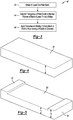
Figure 3 is a flowchart diagram summarizing an example method of making a fuel cell component according to an embodiment of this invention. -
Figure 4 illustrates an example blank plate embodiment. -
Figure 5 illustrates another example blank plate embodiment. -
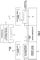
Figure 6 schematically illustrates a molding method and molding machinery according to an embodiment of this invention. -
Figure 7 is a flowchart diagram summarizing an example fuel cell component manufacturing process. -
Figure 8 illustrates a melting point feature of an example prior art polymer. -
Figure 1 illustrates an examplefuel cell component 20, which is a bipolar separator plate. A plurality ofchannels 22 are provided on oneside 24 of the plate for directing a reactant within a fuel cell to facilitate an electrochemical reaction. A plurality offlow field channels 26 are provided on anopposite side 28 of the example plate for directing another reactant within a fuel cell. While a bipolar separator plate including flow field channels is shown as an example fuel cell component, other components may be made using a method designed according to an embodiment consistent with that described below. -
Figure 2 schematically illustrates various portions of the examplefuel cell component 20. Anactive area 30 extends across a majority of the surface area of theplate 20. Theactive area 30 is that portion of theplate 20 where reactants are involved in the electrochemical reaction within the fuel cell. Only some of thechannels Figure 2 for discussion purposes. An example embodiment may include on the order of 150flow channels 22 on one side of theplate 20 and a similar number of thechannels 26 on an opposite side. - The
active area 30 has a first areal density D1. Twoedges 32 of theplate 20 have a second areal density D2, which is greater than the first density D1 of theactive area 30. Theedges 32 serve as seal areas to control movement of reactants within the fuel cell. Twoother edges 34 of theplate 20 also serve as seal regions and include a third areal density D3. In some examples, the second density D2 and the third density D3 are approximately equal. In an example embodiment where theplate 20 comprises a bipolar separator plate for a phosphoric acid fuel cell, the first areal density D1 is on the order of 0.50 gm/sq-cm, the second areal density D2 and the third areal density D3 are on the order of 0.58-0.62 gm/sq-cm. - In the example of
Figure 2 , there arecorner regions 36 that include a fourth areal density D4. In an example embodiment of a phosphoric acid fuel cell separator plate, the fourth areal density D4 is on the order of 0.70 gm/sq-cm. -
Figure 3 includes a flow chart diagram 40 that summarizes an example approach for making a fuel cell component, such as the separator plate shown inFigures 1 and 2 . At 42, the process beings by obtaining at least one blank plate. At 44 a temperature of the blank plate is established to maintain a polymer of the blank plate in an at least partially molten state. In examples where the blank plate comprises fluorinated ethylene propylene (FEP) or a similar polymer and graphite, the temperature used at 44 will be on the order of 300-380° C. Polymers such as FEP may be considered completely melted in a temperature range of 300-380° C. FEP, for example, begins to solidity at a temperature of about 275° C. - At 46, a compression molding force is applied to the blank plate to form a plate having a plurality of channels.
-
Figures 4 and 5 show example blank plate configurations. A firstblank plate arrangement 50 is shown inFigure 4 . This example includes an essentially uniform thickness t along the entire cross section of theblank plate 50. In the example ofFigure 5 , the blank plate 50' has a first thickness t1 and a second, greater thickness t2 along edges 52 and 54, which are generally parallel to each other. One aspect of the blank plate 50' fromFigure 5 compared to that ofFigure 4 is that thethicker edges 52 and 54 facilitate establishing higher densities of the seal regions along edges of the eventually formed fuel cell component. The larger thickness t2 and the slow lateral flow of the mixture used for establishing the fuel cell component (e.g., 85% flake graphite and 15% FEP) facilitate establishing higher density seal regions along the edges of the eventually formed fuel cell component. -
Figure 6 schematically showsmachinery 60 configured to make fuel cell components. Ablank plate 50 is situated on thesurface 62 of aheating station 64. In some examples, theblank plate 50 is obtained using an extrusion molding process. The extrusion mold (not illustrated) heats the graphite and polymer mixture to a temperature sufficient to melt the polymer. In the case of FEP, the extruder may heat the mixture to a temperature in the range from about 300° C to about 380° C. Theheating station 64 facilitates maintaining a desired temperature of theblank plate 50. An extruded blank may be at a temperature between 300° C and 380° C. Theheating station 64 facilitates maintaining that temperature to keep the polymer in an at least partially molten state. - In other examples, the
blank plate 50 is obtained using a compression molding process. In some such examples, theblank plate 50 will be placed onto thesurface 62 when the temperature of the polymer has dropped below a temperature at which the polymer solidifies. In such examples, theheating station 64 increases the temperature of theblank plate 50 to establish a temperature that is sufficient to maintain the polymer in an at least partially molten state. - This example includes a
compression mold 70 havingplatens platens platens mold 70 is on the order of 1,000 to 2,000 psi (7,000 to 14,000 kPa). Themold device 70 is a quick closing style press so that the compression molding force is applied to theblank plate 50 while the temperature of the blank is still high enough so that the polymer is in an at least partially molten state. - With the established temperature of the
blank plate 50 sufficiently high, atransfer mechanism 66 removes theblank plate 50 from thesurface 62 and places it onto the lower mold platen 74.Themold device 70 will remain closed with pressure being applied to the material within the mold until the polymer is essentially solidified and reaches a temperature corresponding to the temperature of theplatens 72 and 74 (e.g., 210° C). - A
transfer mechanism 80 is configured to remove the moldedfuel cell component 20 from thelower mold platen 74 and situate it on a cooling device 82, such as a quench table. Once thecomponent 20 has sufficiently cooled, it may be placed in a fuel cell or an inventory of fuel cell components. - In some embodiments, the
transfer mechanisms 66 and 68 are forklift and transfer devices that include telescoping forks that can move the blank plate or molded fuel cell component from one position into another with great precision. Some example embodiments include a fork transfer device that utilizes a vacuum for lifting and holding the blank plate or molded component. -
Figure 7 includes a flow chart diagram 90 that summarizes an example approach of using an arrangement such as that shown inFigure 6 . Polymer, such asFEP powder 92, andgraphite powder 94 are appropriately weighed out at 96 to achieve a desired mixture. For example, the mixture may comprise 85% graphite powder and 15% FEP. The FEP and graphite are blended at 98. The polymer is melted and the FEP and graphite are mixed in a screw extruder at 100. When FEP is the selected polymer, the extruder heats the polymer to a temperature on the order of 300 to 380° C. - At 102, a blank plate is continuously extruded at a temperature of at least 300° C. In this example, the blank plate has a density on the order of 2.1 to 2.2 gms/ml. At 104, the blank plate is cut to length. At 106 the blank plate is transferred to a molding press such as the
molding device 70. This transfer occurs while the blank plate is still hot enough so that the polymer is in an at least partially molten state. - At 108, a compression molding force is applied to mold the fuel cell component, such as a bipolar plate. As described above, a compression molding force on the order of 1,000 to 2,000 psi is applied using platens that are maintained at a temperature on the order of 200 to 210° C. At 110, the molded
fuel cell component 20 is ejected from the molding device and transferred to a cooling device such as a quench table. - Using a blank plate 50' as shown in
Figure 5 facilitates establishing different material densities in the eventually molded fuel cell component. A single blank plate like that shown inFigure 5 has more material at theedges 52 and 54 compared to the central region of the blank plate 50'. During compression molding, the additional material at theedges 52 and 54 results in a higher density of the molded component along those edges, in part, because of the slow lateral flow of the material within the mold. - Situating two blank plates 50' relative to each other so that the
edges 52 and 54 of one blank plate are perpendicular to theedges 52 and 54 of the other blank plate provides four edges having more material than the amount of material along the central region of the blank plates 50'. When the two blank plates situated adjacent each other in this orientation are subjected to compression molding, the four edges of the resulting component have a higher material density compared to the central region, which corresponds to an active region of a flow field plate, for example. - While various embodiments and examples are described above, the features of each embodiment are not necessarily restricted to any particular embodiment. One or more features of any of the embodiments may be combined with one or more features of another embodiment.
- The preceding description is illustrative rather than limiting in nature. Variations and modifications to the disclosed embodiments may become apparent that do not necessarily depart from the essence of this invention. The scope of legal protection can only be determined by studying the following claims.
Claims (16)
- A method of making a fuel cell component (20), comprising the steps of:obtaining at least one blank plate (50') comprising graphite and a polymer;establishing a temperature of the blank plate (50') that is sufficient to maintain the polymer in an at least partially molten state; andapplying a compression molding force to the blank plate (50') at least until the polymer essentially solidifies to form a plate including a plurality of channels (22) on at least one side of the plate;wherein the blank plate (50') has a central area having a first thickness;wherein the blank plate (50') has two generally parallel edges (52, 54) on opposite sides of the central area; andwherein the edges (52, 54) have a second thickness that is greater than the first thickness.
- The method of claim 1, wherein obtaining the blank plate (50') comprises extrusion molding a mixture of the graphite and the polymer to form the blank plate (50').
- The method of claim 2, comprising
extrusion molding the blank plate (50');
subsequently transferring the blank plate (50') into a compression mold (70) while the temperature is the established temperature; and
applying the compression molding force in the compression mold (70). - The method of claim 2, wherein
establishing the temperature of the blank plate (50') occurs during the extrusion molding; and
applying the compression molding force occurs subsequent to the extrusion molding and before the temperature of the extruded blank plate cools below the temperature at which the polymer is solidified. - The method of claim 1, wherein obtaining the blank plate comprises compression molding a mixture of the graphite and the polymer to form the blank plate (50').
- The method of claim 5, wherein establishing a temperature of the blank plate (50') comprises
heating the blank plate (50') subsequent to the compression molding and prior to applying the compression molding force. - The method of claim 1, wherein the established temperature is at least 300° C.
- The method of claim 7, wherein the established temperature is between 300 °C and 380 °C.
- The method of claim 1, comprising applying the compression molding force until the temperature of the plate is about 200° C.
- The method of claim 1, wherein the compression molding force is at least 7,000 kPa (1000 psi).
- The method of claim 10, wherein the compression molding force is between 7,000 kPa and 14,000 kPa (1000 psi and 2000 psi).
- The method of claim 1, wherein
the formed plate has a first areal density along the central area; and
the formed plate has a second, greater areal density along the two edges. - The method of claim 1, comprising
obtaining a first blank plate (50') that has two generally parallel first edges (52, 54) that are thicker than a central portion of the first blank plate (50');
obtaining a second blank plate (50') that has two generally parallel second edges (52, 54) that are thicker than a central portion of the second blank plate (50');
situating the first blank plate adjacent the second blank plate (50') with the first edges generally perpendicular to the second edges; and
applying the compression molding force to the situated first and second blank plates. - The method of claim 1, wherein the polymer comprises fluorinated ethylene propylene (FEP).
- The method of claim 1, wherein the graphite comprises flake graphite.
- The method of claim 1, wherein the formed plate comprises a bipolar separator plate.
Applications Claiming Priority (1)
| Application Number | Priority Date | Filing Date | Title |
|---|---|---|---|
| PCT/US2014/018844 WO2015130280A1 (en) | 2014-02-27 | 2014-02-27 | Molding process for making fuel cell components |
Publications (3)
| Publication Number | Publication Date |
|---|---|
| EP3111497A1 EP3111497A1 (en) | 2017-01-04 |
| EP3111497A4 EP3111497A4 (en) | 2017-08-02 |
| EP3111497B1 true EP3111497B1 (en) | 2018-08-08 |
Family
ID=54009453
Family Applications (1)
| Application Number | Title | Priority Date | Filing Date |
|---|---|---|---|
| EP14884192.7A Not-in-force EP3111497B1 (en) | 2014-02-27 | 2014-02-27 | Molding process for making fuel cell components |
Country Status (4)
| Country | Link |
|---|---|
| US (1) | US11557770B2 (en) |
| EP (1) | EP3111497B1 (en) |
| KR (1) | KR102159422B1 (en) |
| WO (1) | WO2015130280A1 (en) |
Families Citing this family (2)
| Publication number | Priority date | Publication date | Assignee | Title |
|---|---|---|---|---|
| JP6947708B2 (en) | 2018-08-29 | 2021-10-13 | 日本特殊陶業株式会社 | Wiring board |
| US11811102B2 (en) * | 2018-09-01 | 2023-11-07 | Clarkson University | Material compositions and methods for porous graphite-polymer composite bipolar plates |
Family Cites Families (12)
| Publication number | Priority date | Publication date | Assignee | Title |
|---|---|---|---|---|
| US4365008A (en) * | 1981-07-27 | 1982-12-21 | United Technologies Corporation | Densified edge seals for fuel cell components |
| US6180275B1 (en) | 1998-11-18 | 2001-01-30 | Energy Partners, L.C. | Fuel cell collector plate and method of fabrication |
| US20020039675A1 (en) * | 1999-11-18 | 2002-04-04 | Braun James C. | Compounding and molding process for fuel cell collector plates |
| JP3673747B2 (en) | 2001-10-25 | 2005-07-20 | 本田技研工業株式会社 | Fuel cell separator and method for producing the same |
| WO2004019438A1 (en) * | 2002-08-23 | 2004-03-04 | Honda Giken Kogyo Kabushiki Kaisha | Fuel cell separator and its manufacturing method |
| TWI241732B (en) | 2002-09-25 | 2005-10-11 | E I Du Pont Canada Company | Mesh reinforced fuel cell separator plate |
| WO2004086540A1 (en) | 2003-03-27 | 2004-10-07 | E.I. Du Pont Canada Company | Post-molding treatment of current collector plates for fuel cells to improve conductivity |
| US20060147781A1 (en) | 2003-07-02 | 2006-07-06 | Yuqi Cai | Fuel cell collector plates containing grafted polyolefins |
| US8758958B2 (en) * | 2004-12-29 | 2014-06-24 | Clearedge Power, Llc | Fuel cell separator plate assembly |
| KR101181836B1 (en) | 2006-04-28 | 2012-09-11 | 삼성에스디아이 주식회사 | Seperater for fuel cell, method of preparing same, and fuel cell system comprising same |
| JP5548680B2 (en) * | 2009-03-30 | 2014-07-16 | 昭和電工株式会社 | Sheet press forming method and fuel cell separator manufacturing method |
| KR101229706B1 (en) * | 2009-03-30 | 2013-02-05 | 쇼와 덴코 가부시키가이샤 | Sheet press molding method and method of fabricating fuel cell separators |
-
2014
- 2014-02-27 EP EP14884192.7A patent/EP3111497B1/en not_active Not-in-force
- 2014-02-27 US US15/121,204 patent/US11557770B2/en active Active
- 2014-02-27 WO PCT/US2014/018844 patent/WO2015130280A1/en not_active Ceased
- 2014-02-27 KR KR1020167026147A patent/KR102159422B1/en active Active
Non-Patent Citations (1)
| Title |
|---|
| None * |
Also Published As
| Publication number | Publication date |
|---|---|
| US20170012298A1 (en) | 2017-01-12 |
| EP3111497A4 (en) | 2017-08-02 |
| US11557770B2 (en) | 2023-01-17 |
| WO2015130280A1 (en) | 2015-09-03 |
| EP3111497A1 (en) | 2017-01-04 |
| KR20160126021A (en) | 2016-11-01 |
| KR102159422B1 (en) | 2020-09-23 |
Similar Documents
| Publication | Publication Date | Title |
|---|---|---|
| EP2801121B1 (en) | Method of manufacturing multiple fuel cell separator plate assemblies | |
| US4115627A (en) | Electrochemical cell comprising a ribbed electrode substrate | |
| DE102013216544B4 (en) | COMPATIBLE FUEL CELL SEAL WITH INTEGRATED SEAL | |
| US11559926B2 (en) | Method of producing separator plates by compaction and a production facility | |
| US6017653A (en) | Method of manufacturing modular molded components for a bipolar battery and the resulting bipolar battery | |
| EP1280217A2 (en) | Fuel-cell separator, production of the same, and fuel cell | |
| US11557770B2 (en) | Molding process for making fuel cell components | |
| JP6394480B2 (en) | Manufacturing method of all solid state battery | |
| KR101765817B1 (en) | Separator for Secondary Battery with Improved Safety at High Temperature and Method of Making the Same | |
| KR101838659B1 (en) | A separator with porous coating layer comprising polyolefin binder polymer and a method of making the same | |
| JP2014235835A (en) | Multilayer separator and battery | |
| US20260027755A1 (en) | Method of producing separator plates by hot compaction | |
| US10418644B2 (en) | Method for manufacturing a composite bipolar plate, composite bipolar plate, uses thereof and fuel cell comprising such a composite bipolar plate | |
| KR101816764B1 (en) | A method of manufacturing separator for electrochemical device and separator for electrochemical device manufactured thereby | |
| WO2017211423A1 (en) | Electrode plate and method of production | |
| JP4889924B2 (en) | Manufacturing method of fuel cell separator | |
| KR20120005183A (en) | Manufacturing method of fuel cell carbon composite separator and fuel cell manufactured therefrom | |
| JP7614608B2 (en) | Manufacturing method of fuel cell separator | |
| KR20260053521A (en) | Separator using polymer binders having high and low MFI, method of manufacturing, and fuel cell having such separator | |
| KR20150113582A (en) | Method for Preparation of Battery Case Using Extruding and Deep Drawing | |
| JP2006289774A (en) | Multi-cavity compression mold for manufacturing fuel cell separator and method for manufacturing fuel cell separator using the same | |
| DE102024123510A1 (en) | Distributor for thickness control in dip coating with molten lithium | |
| JP2005339874A (en) | Mold for manufacturing fuel cell separator and method for manufacturing fuel cell separator using the same | |
| JP2005222819A (en) | Manufacturing method of fuel cell separator | |
| JP2011029190A (en) | Separator for fuel cell and method for manufacturing the same |
Legal Events
| Date | Code | Title | Description |
|---|---|---|---|
| PUAI | Public reference made under article 153(3) epc to a published international application that has entered the european phase |
Free format text: ORIGINAL CODE: 0009012 |
|
| STAA | Information on the status of an ep patent application or granted ep patent |
Free format text: STATUS: REQUEST FOR EXAMINATION WAS MADE |
|
| 17P | Request for examination filed |
Effective date: 20160824 |
|
| AK | Designated contracting states |
Kind code of ref document: A1 Designated state(s): AL AT BE BG CH CY CZ DE DK EE ES FI FR GB GR HR HU IE IS IT LI LT LU LV MC MK MT NL NO PL PT RO RS SE SI SK SM TR |
|
| AX | Request for extension of the european patent |
Extension state: BA ME |
|
| DAX | Request for extension of the european patent (deleted) | ||
| A4 | Supplementary search report drawn up and despatched |
Effective date: 20170704 |
|
| RIC1 | Information provided on ipc code assigned before grant |
Ipc: H01M 8/086 20160101ALI20170628BHEP Ipc: H01M 8/02 20160101AFI20170628BHEP Ipc: B29C 43/02 20060101ALI20170628BHEP Ipc: H01M 8/0226 20160101ALI20170628BHEP Ipc: H01M 8/0213 20160101ALI20170628BHEP Ipc: B29C 43/00 20060101ALI20170628BHEP Ipc: B29L 31/34 20060101ALI20170628BHEP Ipc: H01M 8/0221 20160101ALI20170628BHEP Ipc: B29K 105/16 20060101ALI20170628BHEP Ipc: B29B 11/10 20060101ALI20170628BHEP Ipc: B29B 13/02 20060101ALI20170628BHEP Ipc: B29K 23/00 20060101ALI20170628BHEP Ipc: H01M 8/04 20160101ALI20170628BHEP Ipc: H01M 8/0258 20160101ALI20170628BHEP |
|
| RIC1 | Information provided on ipc code assigned before grant |
Ipc: H01M 8/0258 20160101ALI20180212BHEP Ipc: H01M 8/0213 20160101ALI20180212BHEP Ipc: B29K 105/16 20060101ALI20180212BHEP Ipc: H01M 8/04 20160101ALI20180212BHEP Ipc: B29K 23/00 20060101ALI20180212BHEP Ipc: B29C 43/02 20060101ALI20180212BHEP Ipc: H01M 8/0221 20160101ALI20180212BHEP Ipc: B29L 31/34 20060101ALI20180212BHEP Ipc: B29B 11/10 20060101ALI20180212BHEP Ipc: B29B 13/02 20060101ALI20180212BHEP Ipc: H01M 8/02 20160101AFI20180212BHEP Ipc: B29C 43/00 20060101ALI20180212BHEP Ipc: H01M 8/0226 20160101ALI20180212BHEP Ipc: H01M 8/086 20160101ALI20180212BHEP |
|
| GRAP | Despatch of communication of intention to grant a patent |
Free format text: ORIGINAL CODE: EPIDOSNIGR1 |
|
| STAA | Information on the status of an ep patent application or granted ep patent |
Free format text: STATUS: GRANT OF PATENT IS INTENDED |
|
| INTG | Intention to grant announced |
Effective date: 20180323 |
|
| GRAS | Grant fee paid |
Free format text: ORIGINAL CODE: EPIDOSNIGR3 |
|
| GRAA | (expected) grant |
Free format text: ORIGINAL CODE: 0009210 |
|
| STAA | Information on the status of an ep patent application or granted ep patent |
Free format text: STATUS: THE PATENT HAS BEEN GRANTED |
|
| AK | Designated contracting states |
Kind code of ref document: B1 Designated state(s): AL AT BE BG CH CY CZ DE DK EE ES FI FR GB GR HR HU IE IS IT LI LT LU LV MC MK MT NL NO PL PT RO RS SE SI SK SM TR |
|
| REG | Reference to a national code |
Ref country code: GB Ref legal event code: FG4D |
|
| REG | Reference to a national code |
Ref country code: CH Ref legal event code: EP Ref country code: AT Ref legal event code: REF Ref document number: 1028026 Country of ref document: AT Kind code of ref document: T Effective date: 20180815 |
|
| REG | Reference to a national code |
Ref country code: IE Ref legal event code: FG4D |
|
| REG | Reference to a national code |
Ref country code: DE Ref legal event code: R096 Ref document number: 602014030251 Country of ref document: DE |
|
| REG | Reference to a national code |
Ref country code: NL Ref legal event code: MP Effective date: 20180808 |
|
| REG | Reference to a national code |
Ref country code: LT Ref legal event code: MG4D |
|
| REG | Reference to a national code |
Ref country code: AT Ref legal event code: MK05 Ref document number: 1028026 Country of ref document: AT Kind code of ref document: T Effective date: 20180808 |
|
| PG25 | Lapsed in a contracting state [announced via postgrant information from national office to epo] |
Ref country code: FI Free format text: LAPSE BECAUSE OF FAILURE TO SUBMIT A TRANSLATION OF THE DESCRIPTION OR TO PAY THE FEE WITHIN THE PRESCRIBED TIME-LIMIT Effective date: 20180808 Ref country code: RS Free format text: LAPSE BECAUSE OF FAILURE TO SUBMIT A TRANSLATION OF THE DESCRIPTION OR TO PAY THE FEE WITHIN THE PRESCRIBED TIME-LIMIT Effective date: 20180808 Ref country code: IS Free format text: LAPSE BECAUSE OF FAILURE TO SUBMIT A TRANSLATION OF THE DESCRIPTION OR TO PAY THE FEE WITHIN THE PRESCRIBED TIME-LIMIT Effective date: 20181208 Ref country code: AT Free format text: LAPSE BECAUSE OF FAILURE TO SUBMIT A TRANSLATION OF THE DESCRIPTION OR TO PAY THE FEE WITHIN THE PRESCRIBED TIME-LIMIT Effective date: 20180808 Ref country code: GR Free format text: LAPSE BECAUSE OF FAILURE TO SUBMIT A TRANSLATION OF THE DESCRIPTION OR TO PAY THE FEE WITHIN THE PRESCRIBED TIME-LIMIT Effective date: 20181109 Ref country code: NO Free format text: LAPSE BECAUSE OF FAILURE TO SUBMIT A TRANSLATION OF THE DESCRIPTION OR TO PAY THE FEE WITHIN THE PRESCRIBED TIME-LIMIT Effective date: 20181108 Ref country code: BG Free format text: LAPSE BECAUSE OF FAILURE TO SUBMIT A TRANSLATION OF THE DESCRIPTION OR TO PAY THE FEE WITHIN THE PRESCRIBED TIME-LIMIT Effective date: 20181108 Ref country code: SE Free format text: LAPSE BECAUSE OF FAILURE TO SUBMIT A TRANSLATION OF THE DESCRIPTION OR TO PAY THE FEE WITHIN THE PRESCRIBED TIME-LIMIT Effective date: 20180808 Ref country code: PL Free format text: LAPSE BECAUSE OF FAILURE TO SUBMIT A TRANSLATION OF THE DESCRIPTION OR TO PAY THE FEE WITHIN THE PRESCRIBED TIME-LIMIT Effective date: 20180808 Ref country code: LT Free format text: LAPSE BECAUSE OF FAILURE TO SUBMIT A TRANSLATION OF THE DESCRIPTION OR TO PAY THE FEE WITHIN THE PRESCRIBED TIME-LIMIT Effective date: 20180808 Ref country code: NL Free format text: LAPSE BECAUSE OF FAILURE TO SUBMIT A TRANSLATION OF THE DESCRIPTION OR TO PAY THE FEE WITHIN THE PRESCRIBED TIME-LIMIT Effective date: 20180808 |
|
| PG25 | Lapsed in a contracting state [announced via postgrant information from national office to epo] |
Ref country code: HR Free format text: LAPSE BECAUSE OF FAILURE TO SUBMIT A TRANSLATION OF THE DESCRIPTION OR TO PAY THE FEE WITHIN THE PRESCRIBED TIME-LIMIT Effective date: 20180808 Ref country code: LV Free format text: LAPSE BECAUSE OF FAILURE TO SUBMIT A TRANSLATION OF THE DESCRIPTION OR TO PAY THE FEE WITHIN THE PRESCRIBED TIME-LIMIT Effective date: 20180808 Ref country code: AL Free format text: LAPSE BECAUSE OF FAILURE TO SUBMIT A TRANSLATION OF THE DESCRIPTION OR TO PAY THE FEE WITHIN THE PRESCRIBED TIME-LIMIT Effective date: 20180808 |
|
| PG25 | Lapsed in a contracting state [announced via postgrant information from national office to epo] |
Ref country code: CZ Free format text: LAPSE BECAUSE OF FAILURE TO SUBMIT A TRANSLATION OF THE DESCRIPTION OR TO PAY THE FEE WITHIN THE PRESCRIBED TIME-LIMIT Effective date: 20180808 Ref country code: RO Free format text: LAPSE BECAUSE OF FAILURE TO SUBMIT A TRANSLATION OF THE DESCRIPTION OR TO PAY THE FEE WITHIN THE PRESCRIBED TIME-LIMIT Effective date: 20180808 Ref country code: ES Free format text: LAPSE BECAUSE OF FAILURE TO SUBMIT A TRANSLATION OF THE DESCRIPTION OR TO PAY THE FEE WITHIN THE PRESCRIBED TIME-LIMIT Effective date: 20180808 Ref country code: EE Free format text: LAPSE BECAUSE OF FAILURE TO SUBMIT A TRANSLATION OF THE DESCRIPTION OR TO PAY THE FEE WITHIN THE PRESCRIBED TIME-LIMIT Effective date: 20180808 |
|
| REG | Reference to a national code |
Ref country code: DE Ref legal event code: R097 Ref document number: 602014030251 Country of ref document: DE |
|
| PG25 | Lapsed in a contracting state [announced via postgrant information from national office to epo] |
Ref country code: SM Free format text: LAPSE BECAUSE OF FAILURE TO SUBMIT A TRANSLATION OF THE DESCRIPTION OR TO PAY THE FEE WITHIN THE PRESCRIBED TIME-LIMIT Effective date: 20180808 Ref country code: DK Free format text: LAPSE BECAUSE OF FAILURE TO SUBMIT A TRANSLATION OF THE DESCRIPTION OR TO PAY THE FEE WITHIN THE PRESCRIBED TIME-LIMIT Effective date: 20180808 Ref country code: SK Free format text: LAPSE BECAUSE OF FAILURE TO SUBMIT A TRANSLATION OF THE DESCRIPTION OR TO PAY THE FEE WITHIN THE PRESCRIBED TIME-LIMIT Effective date: 20180808 |
|
| PLBE | No opposition filed within time limit |
Free format text: ORIGINAL CODE: 0009261 |
|
| STAA | Information on the status of an ep patent application or granted ep patent |
Free format text: STATUS: NO OPPOSITION FILED WITHIN TIME LIMIT |
|
| 26N | No opposition filed |
Effective date: 20190509 |
|
| PG25 | Lapsed in a contracting state [announced via postgrant information from national office to epo] |
Ref country code: SI Free format text: LAPSE BECAUSE OF FAILURE TO SUBMIT A TRANSLATION OF THE DESCRIPTION OR TO PAY THE FEE WITHIN THE PRESCRIBED TIME-LIMIT Effective date: 20180808 |
|
| REG | Reference to a national code |
Ref country code: CH Ref legal event code: PL |
|
| PG25 | Lapsed in a contracting state [announced via postgrant information from national office to epo] |
Ref country code: MC Free format text: LAPSE BECAUSE OF FAILURE TO SUBMIT A TRANSLATION OF THE DESCRIPTION OR TO PAY THE FEE WITHIN THE PRESCRIBED TIME-LIMIT Effective date: 20180808 Ref country code: LU Free format text: LAPSE BECAUSE OF NON-PAYMENT OF DUE FEES Effective date: 20190227 |
|
| REG | Reference to a national code |
Ref country code: BE Ref legal event code: MM Effective date: 20190228 |
|
| REG | Reference to a national code |
Ref country code: IE Ref legal event code: MM4A |
|
| PG25 | Lapsed in a contracting state [announced via postgrant information from national office to epo] |
Ref country code: CH Free format text: LAPSE BECAUSE OF NON-PAYMENT OF DUE FEES Effective date: 20190228 Ref country code: LI Free format text: LAPSE BECAUSE OF NON-PAYMENT OF DUE FEES Effective date: 20190228 |
|
| PG25 | Lapsed in a contracting state [announced via postgrant information from national office to epo] |
Ref country code: IE Free format text: LAPSE BECAUSE OF NON-PAYMENT OF DUE FEES Effective date: 20190227 |
|
| PG25 | Lapsed in a contracting state [announced via postgrant information from national office to epo] |
Ref country code: FR Free format text: LAPSE BECAUSE OF NON-PAYMENT OF DUE FEES Effective date: 20190228 Ref country code: BE Free format text: LAPSE BECAUSE OF NON-PAYMENT OF DUE FEES Effective date: 20190228 |
|
| PG25 | Lapsed in a contracting state [announced via postgrant information from national office to epo] |
Ref country code: TR Free format text: LAPSE BECAUSE OF FAILURE TO SUBMIT A TRANSLATION OF THE DESCRIPTION OR TO PAY THE FEE WITHIN THE PRESCRIBED TIME-LIMIT Effective date: 20180808 |
|
| PG25 | Lapsed in a contracting state [announced via postgrant information from national office to epo] |
Ref country code: MT Free format text: LAPSE BECAUSE OF NON-PAYMENT OF DUE FEES Effective date: 20190227 Ref country code: PT Free format text: LAPSE BECAUSE OF FAILURE TO SUBMIT A TRANSLATION OF THE DESCRIPTION OR TO PAY THE FEE WITHIN THE PRESCRIBED TIME-LIMIT Effective date: 20181208 |
|
| PG25 | Lapsed in a contracting state [announced via postgrant information from national office to epo] |
Ref country code: CY Free format text: LAPSE BECAUSE OF FAILURE TO SUBMIT A TRANSLATION OF THE DESCRIPTION OR TO PAY THE FEE WITHIN THE PRESCRIBED TIME-LIMIT Effective date: 20180808 |
|
| PG25 | Lapsed in a contracting state [announced via postgrant information from national office to epo] |
Ref country code: HU Free format text: LAPSE BECAUSE OF FAILURE TO SUBMIT A TRANSLATION OF THE DESCRIPTION OR TO PAY THE FEE WITHIN THE PRESCRIBED TIME-LIMIT; INVALID AB INITIO Effective date: 20140227 |
|
| PG25 | Lapsed in a contracting state [announced via postgrant information from national office to epo] |
Ref country code: MK Free format text: LAPSE BECAUSE OF FAILURE TO SUBMIT A TRANSLATION OF THE DESCRIPTION OR TO PAY THE FEE WITHIN THE PRESCRIBED TIME-LIMIT Effective date: 20180808 |
|
| PGFP | Annual fee paid to national office [announced via postgrant information from national office to epo] |
Ref country code: DE Payment date: 20231229 Year of fee payment: 11 Ref country code: GB Payment date: 20240108 Year of fee payment: 11 |
|
| PGFP | Annual fee paid to national office [announced via postgrant information from national office to epo] |
Ref country code: IT Payment date: 20240111 Year of fee payment: 11 |
|
| REG | Reference to a national code |
Ref country code: DE Ref legal event code: R119 Ref document number: 602014030251 Country of ref document: DE |
|
| GBPC | Gb: european patent ceased through non-payment of renewal fee |
Effective date: 20250227 |
|
| PG25 | Lapsed in a contracting state [announced via postgrant information from national office to epo] |
Ref country code: DE Free format text: LAPSE BECAUSE OF NON-PAYMENT OF DUE FEES Effective date: 20250902 |
|
| PG25 | Lapsed in a contracting state [announced via postgrant information from national office to epo] |
Ref country code: GB Free format text: LAPSE BECAUSE OF NON-PAYMENT OF DUE FEES Effective date: 20250227 |
|
| PG25 | Lapsed in a contracting state [announced via postgrant information from national office to epo] |
Ref country code: IT Free format text: LAPSE BECAUSE OF NON-PAYMENT OF DUE FEES Effective date: 20250227 |