EP3111246B1 - Real-time location system in wireless sensor network - Google Patents
Real-time location system in wireless sensor network Download PDFInfo
- Publication number
- EP3111246B1 EP3111246B1 EP15755714.1A EP15755714A EP3111246B1 EP 3111246 B1 EP3111246 B1 EP 3111246B1 EP 15755714 A EP15755714 A EP 15755714A EP 3111246 B1 EP3111246 B1 EP 3111246B1
- Authority
- EP
- European Patent Office
- Prior art keywords
- location
- information
- real
- markers
- marker
- Prior art date
- Legal status (The legal status is an assumption and is not a legal conclusion. Google has not performed a legal analysis and makes no representation as to the accuracy of the status listed.)
- Active
Links
Images




Classifications
-
- G—PHYSICS
- G07—CHECKING-DEVICES
- G07C—TIME OR ATTENDANCE REGISTERS; REGISTERING OR INDICATING THE WORKING OF MACHINES; GENERATING RANDOM NUMBERS; VOTING OR LOTTERY APPARATUS; ARRANGEMENTS, SYSTEMS OR APPARATUS FOR CHECKING NOT PROVIDED FOR ELSEWHERE
- G07C9/00—Individual registration on entry or exit
- G07C9/20—Individual registration on entry or exit involving the use of a pass
- G07C9/27—Individual registration on entry or exit involving the use of a pass with central registration
-
- A—HUMAN NECESSITIES
- A61—MEDICAL OR VETERINARY SCIENCE; HYGIENE
- A61B—DIAGNOSIS; SURGERY; IDENTIFICATION
- A61B17/00—Surgical instruments, devices or methods
-
- G—PHYSICS
- G01—MEASURING; TESTING
- G01S—RADIO DIRECTION-FINDING; RADIO NAVIGATION; DETERMINING DISTANCE OR VELOCITY BY USE OF RADIO WAVES; LOCATING OR PRESENCE-DETECTING BY USE OF THE REFLECTION OR RERADIATION OF RADIO WAVES; ANALOGOUS ARRANGEMENTS USING OTHER WAVES
- G01S13/00—Systems using the reflection or reradiation of radio waves, e.g. radar systems; Analogous systems using reflection or reradiation of waves whose nature or wavelength is irrelevant or unspecified
- G01S13/74—Systems using reradiation of radio waves, e.g. secondary radar systems; Analogous systems
- G01S13/76—Systems using reradiation of radio waves, e.g. secondary radar systems; Analogous systems wherein pulse-type signals are transmitted
- G01S13/765—Systems using reradiation of radio waves, e.g. secondary radar systems; Analogous systems wherein pulse-type signals are transmitted with exchange of information between interrogator and responder
-
- G—PHYSICS
- G01—MEASURING; TESTING
- G01S—RADIO DIRECTION-FINDING; RADIO NAVIGATION; DETERMINING DISTANCE OR VELOCITY BY USE OF RADIO WAVES; LOCATING OR PRESENCE-DETECTING BY USE OF THE REFLECTION OR RERADIATION OF RADIO WAVES; ANALOGOUS ARRANGEMENTS USING OTHER WAVES
- G01S13/00—Systems using the reflection or reradiation of radio waves, e.g. radar systems; Analogous systems using reflection or reradiation of waves whose nature or wavelength is irrelevant or unspecified
- G01S13/87—Combinations of radar systems, e.g. primary radar and secondary radar
- G01S13/876—Combination of several spaced transponders or reflectors of known location for determining the position of a receiver
-
- G—PHYSICS
- G01—MEASURING; TESTING
- G01S—RADIO DIRECTION-FINDING; RADIO NAVIGATION; DETERMINING DISTANCE OR VELOCITY BY USE OF RADIO WAVES; LOCATING OR PRESENCE-DETECTING BY USE OF THE REFLECTION OR RERADIATION OF RADIO WAVES; ANALOGOUS ARRANGEMENTS USING OTHER WAVES
- G01S5/00—Position-fixing by co-ordinating two or more direction or position line determinations; Position-fixing by co-ordinating two or more distance determinations
- G01S5/02—Position-fixing by co-ordinating two or more direction or position line determinations; Position-fixing by co-ordinating two or more distance determinations using radio waves
- G01S5/0205—Details
- G01S5/0236—Assistance data, e.g. base station almanac
-
- G—PHYSICS
- G01—MEASURING; TESTING
- G01S—RADIO DIRECTION-FINDING; RADIO NAVIGATION; DETERMINING DISTANCE OR VELOCITY BY USE OF RADIO WAVES; LOCATING OR PRESENCE-DETECTING BY USE OF THE REFLECTION OR RERADIATION OF RADIO WAVES; ANALOGOUS ARRANGEMENTS USING OTHER WAVES
- G01S5/00—Position-fixing by co-ordinating two or more direction or position line determinations; Position-fixing by co-ordinating two or more distance determinations
- G01S5/02—Position-fixing by co-ordinating two or more direction or position line determinations; Position-fixing by co-ordinating two or more distance determinations using radio waves
- G01S5/0284—Relative positioning
-
- G—PHYSICS
- G01—MEASURING; TESTING
- G01S—RADIO DIRECTION-FINDING; RADIO NAVIGATION; DETERMINING DISTANCE OR VELOCITY BY USE OF RADIO WAVES; LOCATING OR PRESENCE-DETECTING BY USE OF THE REFLECTION OR RERADIATION OF RADIO WAVES; ANALOGOUS ARRANGEMENTS USING OTHER WAVES
- G01S5/00—Position-fixing by co-ordinating two or more direction or position line determinations; Position-fixing by co-ordinating two or more distance determinations
- G01S5/02—Position-fixing by co-ordinating two or more direction or position line determinations; Position-fixing by co-ordinating two or more distance determinations using radio waves
- G01S5/0295—Proximity-based methods, e.g. position inferred from reception of particular signals
-
- G—PHYSICS
- G06—COMPUTING OR CALCULATING; COUNTING
- G06F—ELECTRIC DIGITAL DATA PROCESSING
- G06F8/00—Arrangements for software engineering
- G06F8/60—Software deployment
- G06F8/61—Installation
- G06F8/63—Image based installation; Cloning; Build to order
-
- G—PHYSICS
- G06—COMPUTING OR CALCULATING; COUNTING
- G06F—ELECTRIC DIGITAL DATA PROCESSING
- G06F9/00—Arrangements for program control, e.g. control units
- G06F9/06—Arrangements for program control, e.g. control units using stored programs, i.e. using an internal store of processing equipment to receive or retain programs
- G06F9/44—Arrangements for executing specific programs
- G06F9/4401—Bootstrapping
- G06F9/4416—Network booting; Remote initial program loading [RIPL]
-
- G—PHYSICS
- G08—SIGNALLING
- G08B—SIGNALLING SYSTEMS, e.g. PERSONAL CALLING SYSTEMS; ORDER TELEGRAPHS; ALARM SYSTEMS
- G08B13/00—Burglar, theft or intruder alarms
- G08B13/18—Actuation by interference with heat, light, or radiation of shorter wavelength; Actuation by intruding sources of heat, light, or radiation of shorter wavelength
- G08B13/189—Actuation by interference with heat, light, or radiation of shorter wavelength; Actuation by intruding sources of heat, light, or radiation of shorter wavelength using passive radiation detection systems
- G08B13/194—Actuation by interference with heat, light, or radiation of shorter wavelength; Actuation by intruding sources of heat, light, or radiation of shorter wavelength using passive radiation detection systems using image scanning and comparing systems
- G08B13/196—Actuation by interference with heat, light, or radiation of shorter wavelength; Actuation by intruding sources of heat, light, or radiation of shorter wavelength using passive radiation detection systems using image scanning and comparing systems using television cameras
- G08B13/19602—Image analysis to detect motion of the intruder, e.g. by frame subtraction
- G08B13/19613—Recognition of a predetermined image pattern or behaviour pattern indicating theft or intrusion
-
- G—PHYSICS
- G08—SIGNALLING
- G08B—SIGNALLING SYSTEMS, e.g. PERSONAL CALLING SYSTEMS; ORDER TELEGRAPHS; ALARM SYSTEMS
- G08B13/00—Burglar, theft or intruder alarms
- G08B13/18—Actuation by interference with heat, light, or radiation of shorter wavelength; Actuation by intruding sources of heat, light, or radiation of shorter wavelength
- G08B13/189—Actuation by interference with heat, light, or radiation of shorter wavelength; Actuation by intruding sources of heat, light, or radiation of shorter wavelength using passive radiation detection systems
- G08B13/194—Actuation by interference with heat, light, or radiation of shorter wavelength; Actuation by intruding sources of heat, light, or radiation of shorter wavelength using passive radiation detection systems using image scanning and comparing systems
- G08B13/196—Actuation by interference with heat, light, or radiation of shorter wavelength; Actuation by intruding sources of heat, light, or radiation of shorter wavelength using passive radiation detection systems using image scanning and comparing systems using television cameras
- G08B13/19634—Electrical details of the system, e.g. component blocks for carrying out specific functions
-
- G—PHYSICS
- G08—SIGNALLING
- G08B—SIGNALLING SYSTEMS, e.g. PERSONAL CALLING SYSTEMS; ORDER TELEGRAPHS; ALARM SYSTEMS
- G08B13/00—Burglar, theft or intruder alarms
- G08B13/18—Actuation by interference with heat, light, or radiation of shorter wavelength; Actuation by intruding sources of heat, light, or radiation of shorter wavelength
- G08B13/189—Actuation by interference with heat, light, or radiation of shorter wavelength; Actuation by intruding sources of heat, light, or radiation of shorter wavelength using passive radiation detection systems
- G08B13/194—Actuation by interference with heat, light, or radiation of shorter wavelength; Actuation by intruding sources of heat, light, or radiation of shorter wavelength using passive radiation detection systems using image scanning and comparing systems
- G08B13/196—Actuation by interference with heat, light, or radiation of shorter wavelength; Actuation by intruding sources of heat, light, or radiation of shorter wavelength using passive radiation detection systems using image scanning and comparing systems using television cameras
- G08B13/19697—Arrangements wherein non-video detectors generate an alarm themselves
-
- G—PHYSICS
- G08—SIGNALLING
- G08B—SIGNALLING SYSTEMS, e.g. PERSONAL CALLING SYSTEMS; ORDER TELEGRAPHS; ALARM SYSTEMS
- G08B25/00—Alarm systems in which the location of the alarm condition is signalled to a central station, e.g. fire or police telegraphic systems
- G08B25/009—Signalling of the alarm condition to a substation whose identity is signalled to a central station, e.g. relaying alarm signals in order to extend communication range
-
- G—PHYSICS
- G08—SIGNALLING
- G08B—SIGNALLING SYSTEMS, e.g. PERSONAL CALLING SYSTEMS; ORDER TELEGRAPHS; ALARM SYSTEMS
- G08B29/00—Checking or monitoring of signalling or alarm systems; Prevention or correction of operating errors, e.g. preventing unauthorised operation
- G08B29/18—Prevention or correction of operating errors
- G08B29/181—Prevention or correction of operating errors due to failing power supply
-
- G—PHYSICS
- G08—SIGNALLING
- G08B—SIGNALLING SYSTEMS, e.g. PERSONAL CALLING SYSTEMS; ORDER TELEGRAPHS; ALARM SYSTEMS
- G08B29/00—Checking or monitoring of signalling or alarm systems; Prevention or correction of operating errors, e.g. preventing unauthorised operation
- G08B29/18—Prevention or correction of operating errors
- G08B29/185—Signal analysis techniques for reducing or preventing false alarms or for enhancing the reliability of the system
- G08B29/188—Data fusion; cooperative systems, e.g. voting among different detectors
-
- G—PHYSICS
- G08—SIGNALLING
- G08B—SIGNALLING SYSTEMS, e.g. PERSONAL CALLING SYSTEMS; ORDER TELEGRAPHS; ALARM SYSTEMS
- G08B7/00—Signalling systems according to two or more of groups G08B3/00 - G08B6/00
- G08B7/06—Signalling systems according to two or more of groups G08B3/00 - G08B6/00 using electric transmission, e.g. involving audible and visible signalling through the use of sound and light sources
- G08B7/062—Signalling systems according to two or more of groups G08B3/00 - G08B6/00 using electric transmission, e.g. involving audible and visible signalling through the use of sound and light sources indicating emergency exits
-
- G—PHYSICS
- G08—SIGNALLING
- G08B—SIGNALLING SYSTEMS, e.g. PERSONAL CALLING SYSTEMS; ORDER TELEGRAPHS; ALARM SYSTEMS
- G08B7/00—Signalling systems according to two or more of groups G08B3/00 - G08B6/00
- G08B7/06—Signalling systems according to two or more of groups G08B3/00 - G08B6/00 using electric transmission, e.g. involving audible and visible signalling through the use of sound and light sources
- G08B7/066—Signalling systems according to two or more of groups G08B3/00 - G08B6/00 using electric transmission, e.g. involving audible and visible signalling through the use of sound and light sources guiding along a path, e.g. evacuation path lighting strip
-
- H—ELECTRICITY
- H04—ELECTRIC COMMUNICATION TECHNIQUE
- H04L—TRANSMISSION OF DIGITAL INFORMATION, e.g. TELEGRAPHIC COMMUNICATION
- H04L12/00—Data switching networks
- H04L12/28—Data switching networks characterised by path configuration, e.g. LAN [Local Area Networks] or WAN [Wide Area Networks]
- H04L12/46—Interconnection of networks
- H04L12/4604—LAN interconnection over a backbone network, e.g. Internet, Frame Relay
- H04L12/462—LAN interconnection over a bridge based backbone
- H04L12/4625—Single bridge functionality, e.g. connection of two networks over a single bridge
-
- H—ELECTRICITY
- H04—ELECTRIC COMMUNICATION TECHNIQUE
- H04L—TRANSMISSION OF DIGITAL INFORMATION, e.g. TELEGRAPHIC COMMUNICATION
- H04L12/00—Data switching networks
- H04L12/64—Hybrid switching systems
- H04L12/6418—Hybrid transport
-
- H—ELECTRICITY
- H04—ELECTRIC COMMUNICATION TECHNIQUE
- H04L—TRANSMISSION OF DIGITAL INFORMATION, e.g. TELEGRAPHIC COMMUNICATION
- H04L43/00—Arrangements for monitoring or testing data switching networks
- H04L43/08—Monitoring or testing based on specific metrics, e.g. QoS, energy consumption or environmental parameters
- H04L43/0876—Network utilisation, e.g. volume of load or congestion level
-
- H—ELECTRICITY
- H04—ELECTRIC COMMUNICATION TECHNIQUE
- H04L—TRANSMISSION OF DIGITAL INFORMATION, e.g. TELEGRAPHIC COMMUNICATION
- H04L61/00—Network arrangements, protocols or services for addressing or naming
- H04L61/09—Mapping addresses
- H04L61/10—Mapping addresses of different types
- H04L61/106—Mapping addresses of different types across networks, e.g. mapping telephone numbers to data network addresses
-
- H—ELECTRICITY
- H04—ELECTRIC COMMUNICATION TECHNIQUE
- H04L—TRANSMISSION OF DIGITAL INFORMATION, e.g. TELEGRAPHIC COMMUNICATION
- H04L67/00—Network arrangements or protocols for supporting network services or applications
- H04L67/01—Protocols
- H04L67/10—Protocols in which an application is distributed across nodes in the network
- H04L67/104—Peer-to-peer [P2P] networks
-
- H—ELECTRICITY
- H04—ELECTRIC COMMUNICATION TECHNIQUE
- H04L—TRANSMISSION OF DIGITAL INFORMATION, e.g. TELEGRAPHIC COMMUNICATION
- H04L67/00—Network arrangements or protocols for supporting network services or applications
- H04L67/01—Protocols
- H04L67/12—Protocols specially adapted for proprietary or special-purpose networking environments, e.g. medical networks, sensor networks, networks in vehicles or remote metering networks
-
- H—ELECTRICITY
- H04—ELECTRIC COMMUNICATION TECHNIQUE
- H04L—TRANSMISSION OF DIGITAL INFORMATION, e.g. TELEGRAPHIC COMMUNICATION
- H04L67/00—Network arrangements or protocols for supporting network services or applications
- H04L67/34—Network arrangements or protocols for supporting network services or applications involving the movement of software or configuration parameters
-
- H—ELECTRICITY
- H04—ELECTRIC COMMUNICATION TECHNIQUE
- H04L—TRANSMISSION OF DIGITAL INFORMATION, e.g. TELEGRAPHIC COMMUNICATION
- H04L9/00—Cryptographic mechanisms or cryptographic arrangements for secret or secure communications; Network security protocols
- H04L9/002—Countermeasures against attacks on cryptographic mechanisms
- H04L9/004—Countermeasures against attacks on cryptographic mechanisms for fault attacks
-
- H—ELECTRICITY
- H04—ELECTRIC COMMUNICATION TECHNIQUE
- H04N—PICTORIAL COMMUNICATION, e.g. TELEVISION
- H04N23/00—Cameras or camera modules comprising electronic image sensors; Control thereof
- H04N23/60—Control of cameras or camera modules
- H04N23/65—Control of camera operation in relation to power supply
-
- H—ELECTRICITY
- H04—ELECTRIC COMMUNICATION TECHNIQUE
- H04N—PICTORIAL COMMUNICATION, e.g. TELEVISION
- H04N5/00—Details of television systems
- H04N5/76—Television signal recording
-
- H—ELECTRICITY
- H04—ELECTRIC COMMUNICATION TECHNIQUE
- H04W—WIRELESS COMMUNICATION NETWORKS
- H04W16/00—Network planning, e.g. coverage or traffic planning tools; Network deployment, e.g. resource partitioning or cells structures
- H04W16/24—Cell structures
- H04W16/26—Cell enhancers or enhancement, e.g. for tunnels, building shadow
-
- H—ELECTRICITY
- H04—ELECTRIC COMMUNICATION TECHNIQUE
- H04W—WIRELESS COMMUNICATION NETWORKS
- H04W24/00—Supervisory, monitoring or testing arrangements
- H04W24/02—Arrangements for optimising operational condition
-
- H—ELECTRICITY
- H04—ELECTRIC COMMUNICATION TECHNIQUE
- H04W—WIRELESS COMMUNICATION NETWORKS
- H04W8/00—Network data management
- H04W8/26—Network addressing or numbering for mobility support
-
- H—ELECTRICITY
- H04—ELECTRIC COMMUNICATION TECHNIQUE
- H04W—WIRELESS COMMUNICATION NETWORKS
- H04W88/00—Devices specially adapted for wireless communication networks, e.g. terminals, base stations or access point devices
- H04W88/02—Terminal devices
- H04W88/04—Terminal devices adapted for relaying to or from another terminal or user
-
- G—PHYSICS
- G08—SIGNALLING
- G08B—SIGNALLING SYSTEMS, e.g. PERSONAL CALLING SYSTEMS; ORDER TELEGRAPHS; ALARM SYSTEMS
- G08B13/00—Burglar, theft or intruder alarms
- G08B13/18—Actuation by interference with heat, light, or radiation of shorter wavelength; Actuation by intruding sources of heat, light, or radiation of shorter wavelength
- G08B13/189—Actuation by interference with heat, light, or radiation of shorter wavelength; Actuation by intruding sources of heat, light, or radiation of shorter wavelength using passive radiation detection systems
- G08B13/194—Actuation by interference with heat, light, or radiation of shorter wavelength; Actuation by intruding sources of heat, light, or radiation of shorter wavelength using passive radiation detection systems using image scanning and comparing systems
- G08B13/196—Actuation by interference with heat, light, or radiation of shorter wavelength; Actuation by intruding sources of heat, light, or radiation of shorter wavelength using passive radiation detection systems using image scanning and comparing systems using television cameras
- G08B13/19602—Image analysis to detect motion of the intruder, e.g. by frame subtraction
- G08B13/19608—Tracking movement of a target, e.g. by detecting an object predefined as a target, using target direction and or velocity to predict its new position
-
- G—PHYSICS
- G08—SIGNALLING
- G08B—SIGNALLING SYSTEMS, e.g. PERSONAL CALLING SYSTEMS; ORDER TELEGRAPHS; ALARM SYSTEMS
- G08B13/00—Burglar, theft or intruder alarms
- G08B13/18—Actuation by interference with heat, light, or radiation of shorter wavelength; Actuation by intruding sources of heat, light, or radiation of shorter wavelength
- G08B13/189—Actuation by interference with heat, light, or radiation of shorter wavelength; Actuation by intruding sources of heat, light, or radiation of shorter wavelength using passive radiation detection systems
- G08B13/194—Actuation by interference with heat, light, or radiation of shorter wavelength; Actuation by intruding sources of heat, light, or radiation of shorter wavelength using passive radiation detection systems using image scanning and comparing systems
- G08B13/196—Actuation by interference with heat, light, or radiation of shorter wavelength; Actuation by intruding sources of heat, light, or radiation of shorter wavelength using passive radiation detection systems using image scanning and comparing systems using television cameras
- G08B13/19665—Details related to the storage of video surveillance data
- G08B13/19671—Addition of non-video data, i.e. metadata, to video stream
-
- G—PHYSICS
- G08—SIGNALLING
- G08B—SIGNALLING SYSTEMS, e.g. PERSONAL CALLING SYSTEMS; ORDER TELEGRAPHS; ALARM SYSTEMS
- G08B25/00—Alarm systems in which the location of the alarm condition is signalled to a central station, e.g. fire or police telegraphic systems
- G08B25/007—Details of data content structure of message packets; data protocols
-
- H—ELECTRICITY
- H04—ELECTRIC COMMUNICATION TECHNIQUE
- H04L—TRANSMISSION OF DIGITAL INFORMATION, e.g. TELEGRAPHIC COMMUNICATION
- H04L2101/00—Indexing scheme associated with group H04L61/00
- H04L2101/60—Types of network addresses
- H04L2101/672—Short addresses
-
- H—ELECTRICITY
- H04—ELECTRIC COMMUNICATION TECHNIQUE
- H04L—TRANSMISSION OF DIGITAL INFORMATION, e.g. TELEGRAPHIC COMMUNICATION
- H04L43/00—Arrangements for monitoring or testing data switching networks
- H04L43/08—Monitoring or testing based on specific metrics, e.g. QoS, energy consumption or environmental parameters
- H04L43/0805—Monitoring or testing based on specific metrics, e.g. QoS, energy consumption or environmental parameters by checking availability
-
- H—ELECTRICITY
- H04—ELECTRIC COMMUNICATION TECHNIQUE
- H04L—TRANSMISSION OF DIGITAL INFORMATION, e.g. TELEGRAPHIC COMMUNICATION
- H04L61/00—Network arrangements, protocols or services for addressing or naming
- H04L61/59—Network arrangements, protocols or services for addressing or naming using proxies for addressing
-
- H—ELECTRICITY
- H04—ELECTRIC COMMUNICATION TECHNIQUE
- H04L—TRANSMISSION OF DIGITAL INFORMATION, e.g. TELEGRAPHIC COMMUNICATION
- H04L67/00—Network arrangements or protocols for supporting network services or applications
- H04L67/01—Protocols
- H04L67/10—Protocols in which an application is distributed across nodes in the network
- H04L67/104—Peer-to-peer [P2P] networks
- H04L67/1044—Group management mechanisms
- H04L67/1051—Group master selection mechanisms
-
- H—ELECTRICITY
- H04—ELECTRIC COMMUNICATION TECHNIQUE
- H04L—TRANSMISSION OF DIGITAL INFORMATION, e.g. TELEGRAPHIC COMMUNICATION
- H04L67/00—Network arrangements or protocols for supporting network services or applications
- H04L67/01—Protocols
- H04L67/10—Protocols in which an application is distributed across nodes in the network
- H04L67/104—Peer-to-peer [P2P] networks
- H04L67/1087—Peer-to-peer [P2P] networks using cross-functional networking aspects
- H04L67/1093—Some peer nodes performing special functions
-
- H—ELECTRICITY
- H04—ELECTRIC COMMUNICATION TECHNIQUE
- H04W—WIRELESS COMMUNICATION NETWORKS
- H04W4/00—Services specially adapted for wireless communication networks; Facilities therefor
- H04W4/30—Services specially adapted for particular environments, situations or purposes
- H04W4/38—Services specially adapted for particular environments, situations or purposes for collecting sensor information
-
- H—ELECTRICITY
- H04—ELECTRIC COMMUNICATION TECHNIQUE
- H04W—WIRELESS COMMUNICATION NETWORKS
- H04W84/00—Network topologies
- H04W84/18—Self-organising networks, e.g. ad-hoc networks or sensor networks
-
- H—ELECTRICITY
- H04—ELECTRIC COMMUNICATION TECHNIQUE
- H04W—WIRELESS COMMUNICATION NETWORKS
- H04W92/00—Interfaces specially adapted for wireless communication networks
- H04W92/02—Inter-networking arrangements
-
- Y—GENERAL TAGGING OF NEW TECHNOLOGICAL DEVELOPMENTS; GENERAL TAGGING OF CROSS-SECTIONAL TECHNOLOGIES SPANNING OVER SEVERAL SECTIONS OF THE IPC; TECHNICAL SUBJECTS COVERED BY FORMER USPC CROSS-REFERENCE ART COLLECTIONS [XRACs] AND DIGESTS
- Y04—INFORMATION OR COMMUNICATION TECHNOLOGIES HAVING AN IMPACT ON OTHER TECHNOLOGY AREAS
- Y04S—SYSTEMS INTEGRATING TECHNOLOGIES RELATED TO POWER NETWORK OPERATION, COMMUNICATION OR INFORMATION TECHNOLOGIES FOR IMPROVING THE ELECTRICAL POWER GENERATION, TRANSMISSION, DISTRIBUTION, MANAGEMENT OR USAGE, i.e. SMART GRIDS
- Y04S40/00—Systems for electrical power generation, transmission, distribution or end-user application management characterised by the use of communication or information technologies, or communication or information technology specific aspects supporting them
-
- Y—GENERAL TAGGING OF NEW TECHNOLOGICAL DEVELOPMENTS; GENERAL TAGGING OF CROSS-SECTIONAL TECHNOLOGIES SPANNING OVER SEVERAL SECTIONS OF THE IPC; TECHNICAL SUBJECTS COVERED BY FORMER USPC CROSS-REFERENCE ART COLLECTIONS [XRACs] AND DIGESTS
- Y04—INFORMATION OR COMMUNICATION TECHNOLOGIES HAVING AN IMPACT ON OTHER TECHNOLOGY AREAS
- Y04S—SYSTEMS INTEGRATING TECHNOLOGIES RELATED TO POWER NETWORK OPERATION, COMMUNICATION OR INFORMATION TECHNOLOGIES FOR IMPROVING THE ELECTRICAL POWER GENERATION, TRANSMISSION, DISTRIBUTION, MANAGEMENT OR USAGE, i.e. SMART GRIDS
- Y04S40/00—Systems for electrical power generation, transmission, distribution or end-user application management characterised by the use of communication or information technologies, or communication or information technology specific aspects supporting them
- Y04S40/18—Network protocols supporting networked applications, e.g. including control of end-device applications over a network
-
- Y—GENERAL TAGGING OF NEW TECHNOLOGICAL DEVELOPMENTS; GENERAL TAGGING OF CROSS-SECTIONAL TECHNOLOGIES SPANNING OVER SEVERAL SECTIONS OF THE IPC; TECHNICAL SUBJECTS COVERED BY FORMER USPC CROSS-REFERENCE ART COLLECTIONS [XRACs] AND DIGESTS
- Y04—INFORMATION OR COMMUNICATION TECHNOLOGIES HAVING AN IMPACT ON OTHER TECHNOLOGY AREAS
- Y04S—SYSTEMS INTEGRATING TECHNOLOGIES RELATED TO POWER NETWORK OPERATION, COMMUNICATION OR INFORMATION TECHNOLOGIES FOR IMPROVING THE ELECTRICAL POWER GENERATION, TRANSMISSION, DISTRIBUTION, MANAGEMENT OR USAGE, i.e. SMART GRIDS
- Y04S40/00—Systems for electrical power generation, transmission, distribution or end-user application management characterised by the use of communication or information technologies, or communication or information technology specific aspects supporting them
- Y04S40/20—Information technology specific aspects, e.g. CAD, simulation, modelling, system security
Definitions
- This description relates to operation of security systems in particular intrusion systems.
- This description relates to operation of security systems in particular physical intrusion and alarm systems installed on commercial or residential premises.
- Sensors types typically include motion detectors, cameras, and proximity sensors (used to determine whether a door or window has been opened).
- One particular type of senor is a badge or tag reader to track movement of an credentialed individual within a premises, such as in a major commercial or industrial facility.
- RTLS Real-time location systems
- Different systems use different technologies to determine the location, but such systems typically use either distance measurement or angle measurement (or a combination of the two) between two or more elements in the system with known locations (e.g., locating elements) and the element in the system that is being located (e.g., a tag).
- US 2005/0052281 AI discloses a location tracking system for tracking the location of items within a controlled area which comprises a plurality of RFID tags located according to the required accuracy of the location determinations.
- Vehicles configured to transport items being tracked include two RFID interrogators configured to acquire RFID information from the plurality of RFID tags and to transmit the RFID tag information to a location authority. The separation of the two RFID interrogators is set based on the spacing of the plurality of RFID tags such that the required accuracy results.
- US 8,400,268 B1 discloses a system comprising a plurality of reference tags affixed to reference locations in a coverage area and configured to form a wireless mesh network.
- the system also includes a call tag configured to communicate with the plurality of reference tags and to collect data regarding the communication with the plurality of reference tags.
- the call tag is configured to send a first signal in response to an event.
- a positioning system is coupled to the wireless mesh network and configured to receive the first signal and the data collected by the call tag.
- the positioning system is further configured to process the data collected by the call tag to determine the call tag location with respect to the plurality of reference tags.
- US 2004/0027243 A1 discloses a system and method for acquisition management of subject position information that utilizes RFID to store position information in position tags.
- Tag programmers receive position information from external positioning systems, such as GPS, from manual inputs, such as keypads, or other tag programmers.
- the tag programmers program each position tag with the received position information. Both the tag programmers and the position tags can be portable or fixed.
- US 2008/0056261 A1 discloses a gateway which enables communication between a personal area network and an Internet Protocol network.
- the gateway includes a first interface device for connecting to the personal area network, a second interface device for connecting to the IP network, and a gateway controller.
- the gateway controller allocates ports on an IP interface to one or more clients in said personal area network, stores a routing table in memory for relating said clients in said personal area network with their corresponding ports, and transfers messages between said personal area network clients and said IP network based on entries in said routing table.
- the gateway may function in conjunction with a gateway proxy.
- EP 1885039 A2 discloses an emergency system for providing an emergency function in which the system is required to provide an autonomous and self-diagnostic capability so the system can be tested when not in operation in an emergency situation.
- a plurality of emergency devices are provided which have transmitters and receivers for producing a mesh network.
- Each device has a processor for establishing a preferred wireless communication link of the mesh network to another device for relaying signals and messages.
- the devices are arranged in subnets and the subnets are also grouped into groups of devices which may cross various subnets so that only one group of devices can be tested at a particular time.
- RTLS real-time location systems
- the difficulty of setting up and determining the position the locating elements requires a person who is highly trained in the use of the system and takes a significant amount of time to deploy.
- the distance between the Locating Elements and the Tag is limited by a number of factors depending on the technology that is used. For line of sight systems such as laser based ranging systems, there can be no obstructions. Even for systems that can penetrate obstructions such as those using Radiating Electromagnetic energy (RF), obstructions decrease the range of these applications.
- RF Radiating Electromagnetic energy
- the accuracy of the tag location is often compromised by a phenomenon called multipath which causes reflected signals to be picked up by the receiver which interfere with the signal enough to cause a decrease in the accuracy of the calculated location or make the location completely inaccurate.
- the location information that is received by the system is typically provided in geographic coordinates. To use this location information, a system translates these coordinates into a location on a map or floor plan of a building such as "on the second floor near the north stairwell of the town hall building.”
- a real-time location system according to claim 1 is provided.
- a method of real-time location tracking according to claim 10 is provided.
- the disclosed real-time location system resolves or mitigates these issues by changing the way the system is deployed and decoupling the setup process from the tag location finding process.
- Example security systems may include an intrusion detection panel that is electrically or wirelessly connected to a variety of sensors.
- Those sensors types may include motion detectors, cameras, and proximity sensors (used, e.g., to determine whether a door or window has been opened).
- proximity sensors used, e.g., to determine whether a door or window has been opened.
- Such systems receive a relatively simple signal (electrically open or closed) from one or more of these sensors to indicate that a particular condition being monitored has changed or become unsecure.
- typical intrusion systems can be set-up to monitor entry doors in a building.
- a proximity sensor senses a magnetic contact and produces an electrically closed circuit.
- the proximity sensor opens the circuit, and sends a signal to the panel indicating that an alarm condition has occurred (e.g., an opened entry door).
- Data collection systems are becoming more common in some applications, such as home safety monitoring.
- Data collection systems employ wireless sensor networks and wireless devices, and may include remote server-based monitoring and report generation.
- wireless sensor networks generally use a combination of wired and wireless links between computing devices, with wireless links usually used for the lowest level connections (e.g., end-node device to hub/gateway).
- the edge (wirelessly-connected) tier of the network is comprised of resource-constrained devices with specific functions. These devices may have a small-to-moderate amount of processing power and memory, and may be battery powered, thus requiring that they conserve energy by spending much of their time in sleep mode.
- a typical model is one where the edge devices generally form a single wireless network in which each end-node communicates directly with its parent node in a hub-and-spoke-style architecture.
- the parent node may be, e.g., an access point on a gateway or a sub-coordinator which is, in turn, connected to the access point or another sub-coordinator.
- FIG. 1 an exemplary (global) distributed network topology for a Wireless Sensor Network (WSN) is shown.
- the distributed network 10 is logically divided into a set of tiers or hierarchical levels 12a-12c.
- the global distributed network topology for the sensor network includes distributed rule engines denoted by the circle element "R" at individual nodes or collections of nodes.
- R distributed rule engines
- an upper tier or hierarchical level 12a of the network are disposed servers and/or virtual servers 14 running a "cloud computing" paradigm that are networked together using well-established networking technology such as Internet protocols or which can be private networks that use none or part of the Internet.
- the distributed network 10 has direct links between devices (nodes) as shown and discussed below.
- the distributed network 10 includes a second logically divided tier or hierarchical level 12b, referred to here as a middle tier that involves gateways 16 located at central, convenient places inside individual buildings and structures. These gateways 16 communicate with servers 14 in the upper tier whether the servers are stand-alone dedicated servers and/or cloud based servers running cloud applications using web programming techniques.
- the middle tier gateways 16 are also shown with both local area network 17a (e.g., Ethernet or 802.11) and cellular network interfaces 17b.
- the distributed network topology also includes a lower tier (edge layer) 12c set of devices that involve fully-functional sensor nodes 18 (e.g., sensor nodes that include wireless devices, e.g., transceivers or at least transmitters, which in FIG. 1 are marked in with an "F") as well as constrained wireless sensor nodes or sensor end-nodes (marked in the FIG. 1 with "C").
- fully-functional sensor nodes 18 e.g., sensor nodes that include wireless devices, e.g., transceivers or at least transmitters, which in FIG. 1 are marked in with an "F"
- constrained wireless sensor nodes or sensor end-nodes marked in the FIG. 1 with "C”
- wired sensors can be included in aspects of the distributed network 10.
- the system 40 includes a positioning transceiver system (PTS) 42, a tag transceiver with location marker programmer (TTLMP) 44, a location marker (LM) 46, a mobile tracking system 48 and a mobile monitoring and display system 50.
- PTS positioning transceiver system
- TTLMP tag transceiver with location marker programmer
- LM location marker
- mobile tracking system 48 a mobile monitoring and display system 50.
- the positioning transceiver system 42 includes a subsystem 42a that determines the position of the positioning transceiver system 42 relative to a global coordinate system such as latitude and longitude.
- a global coordinate system such as latitude and longitude.
- An example of such a system would be a GPS receiver.
- the PTS 42 also includes a traditional positioning element 42b that is used to determine the distance or angle to the traditional tag.
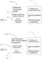
- the system 42 also includes circuitry 43 including a microprocessor and memory subsystem 43a that is used to control the elements of the positioning transceiver system 42, (as well as a Battery and Power Electronics subsystem 43c that supplies power to the system during operation and a communications subsystem 43b that provides data and time synchronization between the various other Positioning Transceiver Systems (not shown), as well as communication of data to the Tagging Transceiver with Location Marker Programmer 44.
- a microprocessor and memory subsystem 43a that is used to control the elements of the positioning transceiver system 42, (as well as a Battery and Power Electronics subsystem 43c that supplies power to the system during operation and a communications subsystem 43b that provides data and time synchronization between the various other Positioning Transceiver Systems (not shown), as well as communication of data to the Tagging Transceiver with Location Marker Programmer 44.
- the tag transceiver with location marker programmer 44 includes an Tag Element 44a that together with the Positioning Elements 42b ( FIG. 3 ) are used to determine the location of the tag transceiver with location marker programmer 44 relative to the global position coordinates, a Location Marker Programmer 44b that is used to program a location marker with the coordinates and user-friendly location information.
- the tag transceiver with location marker programmer 44 also includes circuitry 45 including microprocessor and memory subsystem 45a (as well as a Battery and Power Electronics subsystem 45c) and a communications subsystem 45b that is used to control the elements of the Tag Transceiver 44a and Location Marker Programmer 44b, supply power to the Tag Transceiver 44a and Location Marker Programmer 44b during operation with the communications subsystem providing data and time synchronization between various Positioning Transceiver Systems.
- circuitry 45 including microprocessor and memory subsystem 45a (as well as a Battery and Power Electronics subsystem 45c) and a communications subsystem 45b that is used to control the elements of the Tag Transceiver 44a and Location Marker Programmer 44b, supply power to the Tag Transceiver 44a and Location Marker Programmer 44b during operation with the communications subsystem providing data and time synchronization between various Positioning Transceiver Systems.
- the Location Marker 46 is shown.
- the location marker 46 is a low cost element that is programmed with geo coordinates of the location that the location marker 46 will be affixed to and/or a user-friendly location (e.g., a user supplied name) by the tag transceiver with location marker programmer 44 ( FIG. 4 ).
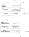
- the location marker 46 includes circuitry 47 including a processor 47a that controls functionality of the location marker 46 and memory 47b that can be programmed with the geo coordinates and / or the friendly location information by the Tag Transceiver with Location Marker Programmer 46 and a communications block 47d that communicates with the Tag Transceiver with Location Marker Programmer 46.
- the location marker 46 is also included in the location marker 46 .
- the antenna 46a can be configured to provide different sensitivity patterns to allow for directional reading.
- the location marker 46 also includes an energy Storage and Power Electronics module 47c that provides power to the system during operation.
- the Location marker 46 may be either powered with an internal battery, an external power source or powered by harvesting power from the Tag Transceiver with Location Marker Programmer 46 during programming and from the mobile monitoring and display system 50 ( FIG. 2 ) during the tracking phase, as discussed below.
- a mobile tracking system 48 is carried by a user and is used to read location information from nearby location markers 46 that are placed around a site.
- the mobile tracking system 48 communicates the geo coordinates and / or the user-friendly location information to the mobile monitoring and display system 50 during the tracking phase of operation.
- the mobile tracking system 48 includes a location marker reader 48a that reads information from location markers 46 during the tracking phase of operation, an antenna 48b that facilitates communication with the Location markers 46 and circuitry 49 including a microprocessor and memory 49a that controls the operation of the individual components of the mobile tracking system 48. Also included in the circuitry 49 are a battery and power electronic block 49b that provides power to the system 48 and a communications block 49c that provides a communication channel between the mobile tracking system 48 and the mobile monitoring and display system 50.
- a mobile monitoring and display system 50 displays the status and geo coordinates and / or user friendly location of one or more mobile tracking systems on a display which may also display maps or floor plans of a site or building.
- the mobile monitoring and display system 50 includes a display 50a that communicates visual and / or audible information about the geo coordinates and / or the user-friendly location information of the mobile tracking systems 48 that are associated with the mobile monitoring and display system 50.
- the mobile monitoring and display system 50 also includes a microprocessor and memory 51a that controls the functionality of the mobile monitoring and display system 50 and battery and power electronics 51b that provides power to operate the mobile monitoring and display system 50 and a communications block 51c that provides a communication channel to one or more mobile tracking systems that are associated with this mobile monitoring and display system 50.
- Setting up the system 40 involves setting up several Positioning Transceiver System elements 42 around a site or building that is to be so equipped. Each of these elements is placed in a known geographic location or in a location where a geographic position receiver system such as GPS would have ability to accurately determine their geo coordinates.
- the Positioning Transceiver Elements are placed in locations that would be within range of the areas of the site or building to be surveyed and equipped with location markers 46.
- a user begins a survey by taking a tag transceiver with location marker programmer 44 to various locations around the site that are to be tagged with location markers 46.
- location markers 46 will be placed in locations such as hallways, doorways, elevators, stairways and other choke points where traffic will move during the tracking phase of operation.
- the tag transceiver with location marker programmer 44 determines the geo coordinates of that location and/or the user enters a user-friendly name (such as "Northwest Stairway, 2 nd Floor") into the tag transceiver with location marker programmer 44.
- the location marker 46 is programmed with the geo location and/or the user-friendly name of the location and the location marker 46 is affixed to the building or site in that location.
- the information can include the type of asset, e.g., smoke detector, exit sign, an id of the asset, the geo coordinates, location in the premises. This process is repeated in each location around the site or building so that the building or site has adequate coverage to allow tracking during the tracking phase of operation.
- location markers 46 during the deployment phase of operation is shown.
- Two location markers 46 are shown with both geo coordinates and user-friendly location names.
- the location marker 46 (right side of the diagram) is being programmed by the tag transceiver with the location marker programmer 44.
- the tags can be programmed with just the user-friendly location information. Even without the geo coordinates, the friendly location name provides significant value for tracking the location during the tracking phase of operation.
- the mobile tracking system 48 is deployed into the site usually affixed to a person or high value asset that is being tracked. As the mobile tracking system 48 moves around the site, the mobile tracking system 48 moves near various location markers 46 that are located around the building or site. As the mobile tracking system 48 reads the various location markers, the mobile tracking system 48 produces a record of the time that the location marker 46 was read and the geo coordinate information and the user-friendly location name on each of the location markers 46. This information is communicated over a communication channel to the mobile monitoring and display system 50. In some cases, more than one mobile tracking system. 48 may be deployed to a site or building that may be individually displayed on the Mobile Monitoring and Display System 50.
- FIGS. 10A and 10B a potential use case with emergency personnel carrying a mobile tracking system 48 as part of their gear is shown.
- the mobile monitoring and display system 50 FIG. 10B
- the mobile tracking system 48 uses location markers (not shown) that may have significant over range of operation allowing the location markers to be read from a large distance away, which could pose a problem.
- the power in the location marker reader may be adjusted down to read only a short distance.
- the antenna size in the location marker and/or the location marker reader may be configured to minimize over-range.
- the location marker may be configured with a narrow beam antenna that could be directed at a specific region to narrow the read-zone and reduce the over-range as shown in FIG. 11 .
- two location markers 46 with narrow beam antennas may be placed nearby one another which could provide direction of motion and the speed of the mobile tracking system 48 as it passes within range of both location markers 46.
- the location marker 46 can contain accuracy information that allows the zone of presence around the location marker 46 to be displayed along with the location information.
- the location marker 46 may store information using encryption techniques that allow only authorized users to read the information.
- the location tracking system 40 may be implemented using any appropriate type of computing device, such as a mainframe work station, a personal computer, a server, a portable computing device, or any other type of intelligent device capable of executing instructions, connecting to a network, and forwarding data packets through the network and can execute any appropriate computer programs to generate, receive, and transmit data packets for use on the network.
- a mainframe work station such as a personal computer, a server, a portable computing device, or any other type of intelligent device capable of executing instructions, connecting to a network, and forwarding data packets through the network and can execute any appropriate computer programs to generate, receive, and transmit data packets for use on the network.
- Each of processes discussed above may be stored on one or more non-transitory machine-readable media, such as computer memory persistent or non-persistent to store executable instructions.
- Each of these devices may also include one or more processing devices (e.g., microprocessors, programmable logic, application-specific integrated circuits, and so forth) for executing the instructions to perform all or part of the functions described herein.
- An example, non-limiting application of the WSN is in a security system for intrusion detection, fire, toxic gas, monitor, etc. installed at one or more premises such as one or more residential houses or building(s) and especially in, e.g., commercial, industrial, buildings, complexes, etc.
- FIG. 13 shows an example of a security system having features of the WSN described with respect to FIG. 1 and having the various functionalities described herein.
- correlation processing receives inputs from certain constrained nodes (although these can also be fully functional nodes). These inputs may include credential information and video information, and the correlation processing may produce correlated results that are sent over the network.
- Context management processing receives inputs from certain constrained nodes (although these can also be fully functional nodes) e.g., credential information and video and grouping information, and performs context processing with results sent over the network.
- the network supports operation of emergency exit indicators; emergency cameras as well as distributed rule processing and rule engine/messaging processing.
- Range extenders are used with e.g., gateways, and a real time location system receives inputs from various sensors (e.g., constrained type) as shown.
- Servers interface to the WSN via a cloud computing configuration and parts of some networks can be run as sub-nets.
- the sensors provide in addition to an indication that something is detected in an area within the range of the sensors, detailed additional information that can be used to evaluate what that indication may be without the intrusion detection panel being required to perform extensive analysis of inputs to the particular sensor.
- a motion detector could be configured to analyze the heat signature of a warm body moving in a room to determine if the body is that of a human or a pet. Results of that analysis would be a message or data that conveys information about the body detected.
- Various sensors thus are used to sense sound, motion, vibration, pressure, heat, images, and so forth, in an appropriate combination to detect a true or verified alarm condition at the intrusion detection panel.
- Recognition software can be used to discriminate between objects that are a human and objects that are an animal; further facial recognition software can be built into video cameras and used to verify that the perimeter intrusion was the result of a recognized, authorized individual.
- video cameras would comprise a processor and memory and the recognition software to process inputs (captured images) by the camera and produce the metadata to convey information regarding recognition or lack of recognition of an individual captured by the video camera.
- the processing could also alternatively or in addition include information regarding characteristic of the individual in the area captured/monitored by the video camera.
- the information would be either metadata received from enhanced motion detectors and video cameras that performed enhanced analysis on inputs to the sensor that gives characteristics of the perimeter intrusion or a metadata resulting from very complex processing that seeks to establish recognition of the object.
- Sensor devices can integrate multiple sensors to generate more complex outputs so that the intrusion detection panel can utilize its processing capabilities to execute algorithms that analyze the environment by building virtual images or signatures of the environment to make an intelligent decision about the validity of a breach.
- Memory stores program instructions and data used by the processor of the intrusion detection panel.
- the memory may be a suitable combination of random access memory and read-only memory, and may host suitable program instructions (e.g. firmware or operating software), and configuration and operating data and may be organized as a file system or otherwise.
- the stored program instruction may include one or more authentication processes for authenticating one or more users.
- the program instructions stored in the memory of the panel may further store software components allowing network communications and establishment of connections to the data network.
- the software components may, for example, include an internet protocol (IP) stack, as well as driver components for the various interfaces, including the interfaces and the keypad . Other software components suitable for establishing a connection and communicating across network will be apparent to those of ordinary skill.
- IP internet protocol
- Program instructions stored in the memory, along with configuration data may control overall operation of the panel.
- the monitoring server includes one or more processing devices (e.g., microprocessors), a network interface and a memory (all not illustrated).
- the monitoring server may physically take the form of a rack mounted card and may be in communication with one or more operator terminals (not shown).
- An example monitoring server is a SURGARD TM SG-System III Virtual, or similar system.
- each monitoring server acts as a controller for each monitoring server, and is in communication with, and controls overall operation, of each server.
- the processor may include, or be in communication with, the memory that stores processor executable instructions controlling the overall operation of the monitoring server.
- Suitable software enable each monitoring server to receive alarms and cause appropriate actions to occur.
- Software may include a suitable Internet protocol (IP) stack and applications/clients.
- IP Internet protocol
- Each monitoring server of the central monitoring station may be associated with an IP address and port(s) by which it communicates with the control panels and/or the user devices to handle alarm events, etc.
- the monitoring server address may be static, and thus always identify a particular one of monitoring server to the intrusion detection panels.
- dynamic addresses could be used, and associated with static domain names, resolved through a domain name service.
- the network interface card interfaces with the network to receive incoming signals, and may for example take the form of an Ethernet network interface card (NIC).
- NIC Ethernet network interface card
- the servers may be computers, thin-clients, or the like, to which received data representative of an alarm event is passed for handling by human operators.
- the monitoring station may further include, or have access to, a subscriber database that includes a database under control of a database engine.
- the database may contain entries corresponding to the various subscriber devices/processes to panels like the panel that are serviced by the monitoring station.
- a computer program product i.e., a computer program tangibly embodied in one or more tangible, physical hardware storage devices that are computer and/or machine-readable storage devices for execution by, or to control the operation of, data processing apparatus, e.g., a programmable processor, a computer, or multiple computers.
- a computer program can be written in any form of programming language, including compiled or interpreted languages, and it can be deployed in any form, including as a stand-alone program or as a module, component, subroutine, or other unit suitable for use in a computing environment.
- a computer program can be deployed to be executed on one computer or on multiple computers at one site or distributed across multiple sites and interconnected by a network.
- Actions associated with implementing the processes can be performed by one or more programmable processors executing one or more computer programs to perform the functions of the calibration process. All or part of the processes can be implemented as, special purpose logic circuitry, e.g., an FPGA (field programmable gate array) and/or an ASIC (application-specific integrated circuit).
- special purpose logic circuitry e.g., an FPGA (field programmable gate array) and/or an ASIC (application-specific integrated circuit).
- processors suitable for the execution of a computer program include, by way of example, both general and special purpose microprocessors, and any one or more processors of any kind of digital computer.
- a processor will receive instructions and data from a read-only storage area or a random access storage area or both.
- Elements of a computer include one or more processors for executing instructions and one or more storage area devices for storing instructions and data.
- a computer will also include, or be operatively coupled to receive data from, or transfer data to, or both, one or more machine-readable storage media, such as mass storage devices for storing data, e.g., magnetic, magneto-optical disks, or optical disks.
Landscapes
- Engineering & Computer Science (AREA)
- Computer Networks & Wireless Communication (AREA)
- Signal Processing (AREA)
- Physics & Mathematics (AREA)
- General Physics & Mathematics (AREA)
- Radar, Positioning & Navigation (AREA)
- Remote Sensing (AREA)
- Computer Security & Cryptography (AREA)
- Health & Medical Sciences (AREA)
- Software Systems (AREA)
- Theoretical Computer Science (AREA)
- Multimedia (AREA)
- General Engineering & Computer Science (AREA)
- General Health & Medical Sciences (AREA)
- Medical Informatics (AREA)
- Business, Economics & Management (AREA)
- Emergency Management (AREA)
- Surgery (AREA)
- Life Sciences & Earth Sciences (AREA)
- Computing Systems (AREA)
- Databases & Information Systems (AREA)
- Animal Behavior & Ethology (AREA)
- Heart & Thoracic Surgery (AREA)
- Molecular Biology (AREA)
- Biomedical Technology (AREA)
- Nuclear Medicine, Radiotherapy & Molecular Imaging (AREA)
- Public Health (AREA)
- Veterinary Medicine (AREA)
- Computer Vision & Pattern Recognition (AREA)
- Environmental & Geological Engineering (AREA)
- Library & Information Science (AREA)
- Mathematical Physics (AREA)
- Alarm Systems (AREA)
- Mobile Radio Communication Systems (AREA)
- Telephonic Communication Services (AREA)
- Stored Programmes (AREA)
- Computer And Data Communications (AREA)
- Cardiology (AREA)
- Data Exchanges In Wide-Area Networks (AREA)
- Time Recorders, Dirve Recorders, Access Control (AREA)
Description
- This description relates to operation of security systems in particular intrusion systems.
- This description relates to operation of security systems in particular physical intrusion and alarm systems installed on commercial or residential premises.
- It is common for businesses and homeowners to have a security system for detecting alarm conditions at their premises and signaling the conditions to a monitoring station or to authorized users of the security system. Sensors types typically include motion detectors, cameras, and proximity sensors (used to determine whether a door or window has been opened). One particular type of senor is a badge or tag reader to track movement of an credentialed individual within a premises, such as in a major commercial or industrial facility.
- Real-time location systems (RTLS) use an active system to determine the current location of a moving tag within an environment. Different systems use different technologies to determine the location, but such systems typically use either distance measurement or angle measurement (or a combination of the two) between two or more elements in the system with known locations (e.g., locating elements) and the element in the system that is being located (e.g., a tag).
-
US 2005/0052281 AI discloses a location tracking system for tracking the location of items within a controlled area which comprises a plurality of RFID tags located according to the required accuracy of the location determinations. Vehicles configured to transport items being tracked include two RFID interrogators configured to acquire RFID information from the plurality of RFID tags and to transmit the RFID tag information to a location authority. The separation of the two RFID interrogators is set based on the spacing of the plurality of RFID tags such that the required accuracy results. -
US 8,400,268 B1 discloses a system comprising a plurality of reference tags affixed to reference locations in a coverage area and configured to form a wireless mesh network. The system also includes a call tag configured to communicate with the plurality of reference tags and to collect data regarding the communication with the plurality of reference tags. The call tag is configured to send a first signal in response to an event. A positioning system is coupled to the wireless mesh network and configured to receive the first signal and the data collected by the call tag. The positioning system is further configured to process the data collected by the call tag to determine the call tag location with respect to the plurality of reference tags. -
US 2004/0027243 A1 discloses a system and method for acquisition management of subject position information that utilizes RFID to store position information in position tags. Tag programmers receive position information from external positioning systems, such as GPS, from manual inputs, such as keypads, or other tag programmers. The tag programmers program each position tag with the received position information. Both the tag programmers and the position tags can be portable or fixed. -
US 2008/0056261 A1 discloses a gateway which enables communication between a personal area network and an Internet Protocol network. The gateway includes a first interface device for connecting to the personal area network, a second interface device for connecting to the IP network, and a gateway controller. In one embodiment, the gateway controller allocates ports on an IP interface to one or more clients in said personal area network, stores a routing table in memory for relating said clients in said personal area network with their corresponding ports, and transfers messages between said personal area network clients and said IP network based on entries in said routing table. The gateway may function in conjunction with a gateway proxy. -
EP 1885039 A2 discloses an emergency system for providing an emergency function in which the system is required to provide an autonomous and self-diagnostic capability so the system can be tested when not in operation in an emergency situation. A plurality of emergency devices are provided which have transmitters and receivers for producing a mesh network. Each device has a processor for establishing a preferred wireless communication link of the mesh network to another device for relaying signals and messages. The devices are arranged in subnets and the subnets are also grouped into groups of devices which may cross various subnets so that only one group of devices can be tested at a particular time. - Several problems limit the efficacy of real-time location systems (RTLS). A traditional RTLS system depends on having accurate position information for each of the locating elements. These locating elements either need to be fixed at an a priori known location or if they are portable elements, the elements location needs top be accurately determined at setup time. GPS is often used to determine the location of portable locating elements. However that is only possible in locations where GPS is functional and accurate (i.e. outdoors without obstructions).
- The difficulty of setting up and determining the position the locating elements requires a person who is highly trained in the use of the system and takes a significant amount of time to deploy. The distance between the Locating Elements and the Tag is limited by a number of factors depending on the technology that is used. For line of sight systems such as laser based ranging systems, there can be no obstructions. Even for systems that can penetrate obstructions such as those using Radiating Electromagnetic energy (RF), obstructions decrease the range of these applications. The accuracy of the tag location is often compromised by a phenomenon called multipath which causes reflected signals to be picked up by the receiver which interfere with the signal enough to cause a decrease in the accuracy of the calculated location or make the location completely inaccurate. The location information that is received by the system is typically provided in geographic coordinates. To use this location information, a system translates these coordinates into a location on a map or floor plan of a building such as "on the second floor near the north stairwell of the town hall building."
- According to an aspect of the present invention, a real-time location system according to
claim 1 is provided. - According to an additional aspect of the present invention, a method of real-time location tracking according to
claim 10 is provided. - The disclosed real-time location system resolves or mitigates these issues by changing the way the system is deployed and decoupling the setup process from the tag location finding process.
- The details of one or more embodiments of the invention are set forth in the accompanying drawings and the description below. Other features, objects, and advantages of the invention is apparent from the description and drawings, and from the claims.
-
-
FIG. 1 is a schematic diagram of an exemplary networked security system. -
FIG. 2 is a block diagram of a real-time location system. -
FIGS. 3-7 are block diagrams of components of the real-time location system ofFIG. 2 . -
FIG. 8 is an exemplary layout plan useful in understanding setup. -
FIGS. 9-12 are diagrams useful in understanding setup and operation of the RTL system ofFIG. 2 . -
FIG. 13 is a block diagram of an example sensor network for physical premises security applications. - Described herein are examples of network features that may be used in various contexts including, but not limited to, security/intrusion and alarm systems. Example security systems may include an intrusion detection panel that is electrically or wirelessly connected to a variety of sensors. Those sensors types may include motion detectors, cameras, and proximity sensors (used, e.g., to determine whether a door or window has been opened). Typically, such systems receive a relatively simple signal (electrically open or closed) from one or more of these sensors to indicate that a particular condition being monitored has changed or become unsecure.
- For example, typical intrusion systems can be set-up to monitor entry doors in a building. When a door is secured, a proximity sensor senses a magnetic contact and produces an electrically closed circuit. When the door is opened, the proximity sensor opens the circuit, and sends a signal to the panel indicating that an alarm condition has occurred (e.g., an opened entry door).
- Data collection systems are becoming more common in some applications, such as home safety monitoring. Data collection systems employ wireless sensor networks and wireless devices, and may include remote server-based monitoring and report generation. As described in more detail below, wireless sensor networks generally use a combination of wired and wireless links between computing devices, with wireless links usually used for the lowest level connections (e.g., end-node device to hub/gateway). In an example network, the edge (wirelessly-connected) tier of the network is comprised of resource-constrained devices with specific functions. These devices may have a small-to-moderate amount of processing power and memory, and may be battery powered, thus requiring that they conserve energy by spending much of their time in sleep mode. A typical model is one where the edge devices generally form a single wireless network in which each end-node communicates directly with its parent node in a hub-and-spoke-style architecture. The parent node may be, e.g., an access point on a gateway or a sub-coordinator which is, in turn, connected to the access point or another sub-coordinator.
- Referring now to
FIG. 1 , an exemplary (global) distributed network topology for a Wireless Sensor Network (WSN) is shown. InFIG. 1 the distributednetwork 10 is logically divided into a set of tiers orhierarchical levels 12a-12c. - The global distributed network topology for the sensor network includes distributed rule engines denoted by the circle element "R" at individual nodes or collections of nodes. In an upper tier or
hierarchical level 12a of the network are disposed servers and/orvirtual servers 14 running a "cloud computing" paradigm that are networked together using well-established networking technology such as Internet protocols or which can be private networks that use none or part of the Internet. - Applications that run on those
servers 14 communicate using various protocols such as for Web Internet networks XML/SOAP, RESTful web service, and other application layer technologies such as HTTP and ATOM. The distributednetwork 10 has direct links between devices (nodes) as shown and discussed below. - The distributed
network 10 includes a second logically divided tier orhierarchical level 12b, referred to here as a middle tier that involvesgateways 16 located at central, convenient places inside individual buildings and structures. Thesegateways 16 communicate withservers 14 in the upper tier whether the servers are stand-alone dedicated servers and/or cloud based servers running cloud applications using web programming techniques. Themiddle tier gateways 16 are also shown with bothlocal area network 17a (e.g., Ethernet or 802.11) andcellular network interfaces 17b. - The distributed network topology also includes a lower tier (edge layer) 12c set of devices that involve fully-functional sensor nodes 18 (e.g., sensor nodes that include wireless devices, e.g., transceivers or at least transmitters, which in
FIG. 1 are marked in with an "F") as well as constrained wireless sensor nodes or sensor end-nodes (marked in theFIG. 1 with "C"). In some examples wired sensors (not shown) can be included in aspects of the distributednetwork 10. - Referring now to
FIG. 2 , a real-time location system 40 using stationary, wireless sensor nodes and a portable transceiver is described. Thesystem 40 includes a positioning transceiver system (PTS) 42, a tag transceiver with location marker programmer (TTLMP) 44, a location marker (LM) 46, amobile tracking system 48 and a mobile monitoring anddisplay system 50. - Referring to
FIG. 3 , thepositioning transceiver system 42 includes asubsystem 42a that determines the position of thepositioning transceiver system 42 relative to a global coordinate system such as latitude and longitude. An example of such a system would be a GPS receiver. ThePTS 42 also includes atraditional positioning element 42b that is used to determine the distance or angle to the traditional tag. Thesystem 42 also includescircuitry 43 including a microprocessor andmemory subsystem 43a that is used to control the elements of thepositioning transceiver system 42, (as well as a Battery andPower Electronics subsystem 43c that supplies power to the system during operation and acommunications subsystem 43b that provides data and time synchronization between the various other Positioning Transceiver Systems (not shown), as well as communication of data to the Tagging Transceiver withLocation Marker Programmer 44. - Referring to
FIG. 4 , the tag transceiver withlocation marker programmer 44 includes anTag Element 44a that together with thePositioning Elements 42b (FIG. 3 ) are used to determine the location of the tag transceiver withlocation marker programmer 44 relative to the global position coordinates, aLocation Marker Programmer 44b that is used to program a location marker with the coordinates and user-friendly location information. The tag transceiver withlocation marker programmer 44 also includescircuitry 45 including microprocessor andmemory subsystem 45a (as well as a Battery andPower Electronics subsystem 45c) and acommunications subsystem 45b that is used to control the elements of theTag Transceiver 44a andLocation Marker Programmer 44b, supply power to theTag Transceiver 44a andLocation Marker Programmer 44b during operation with the communications subsystem providing data and time synchronization between various Positioning Transceiver Systems. - Referring to
FIG. 5 , theLocation Marker 46 is shown. Thelocation marker 46 is a low cost element that is programmed with geo coordinates of the location that thelocation marker 46 will be affixed to and/or a user-friendly location (e.g., a user supplied name) by the tag transceiver with location marker programmer 44 (FIG. 4 ). Thelocation marker 46 includescircuitry 47 including aprocessor 47a that controls functionality of thelocation marker 46 andmemory 47b that can be programmed with the geo coordinates and / or the friendly location information by the Tag Transceiver withLocation Marker Programmer 46 and acommunications block 47d that communicates with the Tag Transceiver withLocation Marker Programmer 46. - Also included in the
location marker 46 is anantenna 46a for thecommunication block 47d. Theantenna 46a can be configured to provide different sensitivity patterns to allow for directional reading. Thelocation marker 46 also includes an energy Storage andPower Electronics module 47c that provides power to the system during operation. TheLocation marker 46 may be either powered with an internal battery, an external power source or powered by harvesting power from the Tag Transceiver withLocation Marker Programmer 46 during programming and from the mobile monitoring and display system 50 (FIG. 2 ) during the tracking phase, as discussed below. - Referring to
FIG. 6 , amobile tracking system 48 is carried by a user and is used to read location information fromnearby location markers 46 that are placed around a site. Themobile tracking system 48 communicates the geo coordinates and / or the user-friendly location information to the mobile monitoring anddisplay system 50 during the tracking phase of operation. Themobile tracking system 48 includes alocation marker reader 48a that reads information fromlocation markers 46 during the tracking phase of operation, anantenna 48b that facilitates communication with theLocation markers 46 andcircuitry 49 including a microprocessor andmemory 49a that controls the operation of the individual components of themobile tracking system 48. Also included in thecircuitry 49 are a battery and power electronic block 49b that provides power to thesystem 48 and acommunications block 49c that provides a communication channel between themobile tracking system 48 and the mobile monitoring anddisplay system 50. - Referring to
FIG. 7 , a mobile monitoring anddisplay system 50 displays the status and geo coordinates and / or user friendly location of one or more mobile tracking systems on a display which may also display maps or floor plans of a site or building. The mobile monitoring anddisplay system 50 includes adisplay 50a that communicates visual and / or audible information about the geo coordinates and / or the user-friendly location information of themobile tracking systems 48 that are associated with the mobile monitoring anddisplay system 50. The mobile monitoring anddisplay system 50 also includes a microprocessor andmemory 51a that controls the functionality of the mobile monitoring anddisplay system 50 and battery and power electronics 51b that provides power to operate the mobile monitoring anddisplay system 50 and acommunications block 51c that provides a communication channel to one or more mobile tracking systems that are associated with this mobile monitoring anddisplay system 50. - Setting up the
system 40 involves setting up several PositioningTransceiver System elements 42 around a site or building that is to be so equipped. Each of these elements is placed in a known geographic location or in a location where a geographic position receiver system such as GPS would have ability to accurately determine their geo coordinates. The Positioning Transceiver Elements are placed in locations that would be within range of the areas of the site or building to be surveyed and equipped withlocation markers 46. - Once the
positioning transceiver system 42 are placed throughout the site, a user begins a survey by taking a tag transceiver withlocation marker programmer 44 to various locations around the site that are to be tagged withlocation markers 46. Typically thelocation markers 46 will be placed in locations such as hallways, doorways, elevators, stairways and other choke points where traffic will move during the tracking phase of operation. When a location is found to place a location marker, the tag transceiver withlocation marker programmer 44 determines the geo coordinates of that location and/or the user enters a user-friendly name (such as "Northwest Stairway, 2nd Floor") into the tag transceiver withlocation marker programmer 44. Thelocation marker 46 is programmed with the geo location and/or the user-friendly name of the location and thelocation marker 46 is affixed to the building or site in that location. The information can include the type of asset, e.g., smoke detector, exit sign, an id of the asset, the geo coordinates, location in the premises. This process is repeated in each location around the site or building so that the building or site has adequate coverage to allow tracking during the tracking phase of operation. - Referring now to
FIG. 8 a typical example of the programming oflocation markers 46 during the deployment phase of operation is shown. In this case there are 3Positioning Transceivers 42 that are placed in 3 locations outside of the building. Twolocation markers 46 are shown with both geo coordinates and user-friendly location names. The location marker 46 (right side of the diagram) is being programmed by the tag transceiver with thelocation marker programmer 44. - According to a non-claimed example of the present disclosure, in the event that it is impractical or otherwise undesirable to determine the geo coordinates of the
various location markers 46 around the site or building, the tags can be programmed with just the user-friendly location information. Even without the geo coordinates, the friendly location name provides significant value for tracking the location during the tracking phase of operation. - Referring now to
FIG. 9 , during the tracking phase of operation, themobile tracking system 48 is deployed into the site usually affixed to a person or high value asset that is being tracked. As themobile tracking system 48 moves around the site, themobile tracking system 48 moves nearvarious location markers 46 that are located around the building or site. As themobile tracking system 48 reads the various location markers, themobile tracking system 48 produces a record of the time that thelocation marker 46 was read and the geo coordinate information and the user-friendly location name on each of thelocation markers 46. This information is communicated over a communication channel to the mobile monitoring anddisplay system 50. In some cases, more than one mobile tracking system. 48 may be deployed to a site or building that may be individually displayed on the Mobile Monitoring andDisplay System 50. - Referring now to
FIGS. 10A and10B , a potential use case with emergency personnel carrying amobile tracking system 48 as part of their gear is shown. In this example, there are 2 firefighters that are located in two different locations around the building. In this example, the mobile monitoring and display system 50 (FIG. 10B ) displays just the friendly name of the last known location of the firefighters and how long ago they were at that location. - The
mobile tracking system 48 uses location markers (not shown) that may have significant over range of operation allowing the location markers to be read from a large distance away, which could pose a problem. There are several approaches to manage that over-range: The power in the location marker reader may be adjusted down to read only a short distance. The antenna size in the location marker and/or the location marker reader may be configured to minimize over-range. The location marker may be configured with a narrow beam antenna that could be directed at a specific region to narrow the read-zone and reduce the over-range as shown inFIG. 11 . Also as shown inFIG. 12 , twolocation markers 46 with narrow beam antennas may be placed nearby one another which could provide direction of motion and the speed of themobile tracking system 48 as it passes within range of bothlocation markers 46. Thelocation marker 46 can contain accuracy information that allows the zone of presence around thelocation marker 46 to be displayed along with the location information. Thelocation marker 46 may store information using encryption techniques that allow only authorized users to read the information. - The
location tracking system 40 may be implemented using any appropriate type of computing device, such as a mainframe work station, a personal computer, a server, a portable computing device, or any other type of intelligent device capable of executing instructions, connecting to a network, and forwarding data packets through the network and can execute any appropriate computer programs to generate, receive, and transmit data packets for use on the network. - Each of processes discussed above may be stored on one or more non-transitory machine-readable media, such as computer memory persistent or non-persistent to store executable instructions. Each of these devices may also include one or more processing devices (e.g., microprocessors, programmable logic, application-specific integrated circuits, and so forth) for executing the instructions to perform all or part of the functions described herein.
- Elements of different implementations described herein may be combined to form other embodiments not specifically set forth above. Elements may be left out of the structures described herein without adversely affecting their operation. Furthermore, various separate elements may be combined into one or more individual elements to perform the functions described herein.
- An example, non-limiting application of the WSN is in a security system for intrusion detection, fire, toxic gas, monitor, etc. installed at one or more premises such as one or more residential houses or building(s) and especially in, e.g., commercial, industrial, buildings, complexes, etc.
-
FIG. 13 shows an example of a security system having features of the WSN described with respect toFIG. 1 and having the various functionalities described herein. As shown inFIG. 13 , correlation processing receives inputs from certain constrained nodes (although these can also be fully functional nodes). These inputs may include credential information and video information, and the correlation processing may produce correlated results that are sent over the network. Context management processing receives inputs from certain constrained nodes (although these can also be fully functional nodes) e.g., credential information and video and grouping information, and performs context processing with results sent over the network. The network supports operation of emergency exit indicators; emergency cameras as well as distributed rule processing and rule engine/messaging processing. Range extenders are used with e.g., gateways, and a real time location system receives inputs from various sensors (e.g., constrained type) as shown. Servers interface to the WSN via a cloud computing configuration and parts of some networks can be run as sub-nets. - The sensors provide in addition to an indication that something is detected in an area within the range of the sensors, detailed additional information that can be used to evaluate what that indication may be without the intrusion detection panel being required to perform extensive analysis of inputs to the particular sensor.
- For example, a motion detector could be configured to analyze the heat signature of a warm body moving in a room to determine if the body is that of a human or a pet. Results of that analysis would be a message or data that conveys information about the body detected. Various sensors thus are used to sense sound, motion, vibration, pressure, heat, images, and so forth, in an appropriate combination to detect a true or verified alarm condition at the intrusion detection panel.
- Recognition software can be used to discriminate between objects that are a human and objects that are an animal; further facial recognition software can be built into video cameras and used to verify that the perimeter intrusion was the result of a recognized, authorized individual. Such video cameras would comprise a processor and memory and the recognition software to process inputs (captured images) by the camera and produce the metadata to convey information regarding recognition or lack of recognition of an individual captured by the video camera. The processing could also alternatively or in addition include information regarding characteristic of the individual in the area captured/monitored by the video camera. Thus, depending on the circumstances, the information would be either metadata received from enhanced motion detectors and video cameras that performed enhanced analysis on inputs to the sensor that gives characteristics of the perimeter intrusion or a metadata resulting from very complex processing that seeks to establish recognition of the object.
- Sensor devices can integrate multiple sensors to generate more complex outputs so that the intrusion detection panel can utilize its processing capabilities to execute algorithms that analyze the environment by building virtual images or signatures of the environment to make an intelligent decision about the validity of a breach.
- Memory stores program instructions and data used by the processor of the intrusion detection panel. The memory may be a suitable combination of random access memory and read-only memory, and may host suitable program instructions (e.g. firmware or operating software), and configuration and operating data and may be organized as a file system or otherwise. The stored program instruction may include one or more authentication processes for authenticating one or more users. The program instructions stored in the memory of the panel may further store software components allowing network communications and establishment of connections to the data network. The software components may, for example, include an internet protocol (IP) stack, as well as driver components for the various interfaces, including the interfaces and the keypad . Other software components suitable for establishing a connection and communicating across network will be apparent to those of ordinary skill.
- Program instructions stored in the memory, along with configuration data may control overall operation of the panel.
- The monitoring server includes one or more processing devices (e.g., microprocessors), a network interface and a memory (all not illustrated). The monitoring server may physically take the form of a rack mounted card and may be in communication with one or more operator terminals (not shown). An example monitoring server is a SURGARD™ SG-System III Virtual, or similar system.
- The processor of each monitoring server acts as a controller for each monitoring server, and is in communication with, and controls overall operation, of each server. The processor may include, or be in communication with, the memory that stores processor executable instructions controlling the overall operation of the monitoring server. Suitable software enable each monitoring server to receive alarms and cause appropriate actions to occur. Software may include a suitable Internet protocol (IP) stack and applications/clients.
- Each monitoring server of the central monitoring station may be associated with an IP address and port(s) by which it communicates with the control panels and/or the user devices to handle alarm events, etc. The monitoring server address may be static, and thus always identify a particular one of monitoring server to the intrusion detection panels. Alternatively, dynamic addresses could be used, and associated with static domain names, resolved through a domain name service.
- The network interface card interfaces with the network to receive incoming signals, and may for example take the form of an Ethernet network interface card (NIC). The servers may be computers, thin-clients, or the like, to which received data representative of an alarm event is passed for handling by human operators. The monitoring station may further include, or have access to, a subscriber database that includes a database under control of a database engine. The database may contain entries corresponding to the various subscriber devices/processes to panels like the panel that are serviced by the monitoring station.
- All or part of the processes described herein and their various modifications (hereinafter referred to as "the processes") can be implemented, at least in part, via a computer program product, i.e., a computer program tangibly embodied in one or more tangible, physical hardware storage devices that are computer and/or machine-readable storage devices for execution by, or to control the operation of, data processing apparatus, e.g., a programmable processor, a computer, or multiple computers. A computer program can be written in any form of programming language, including compiled or interpreted languages, and it can be deployed in any form, including as a stand-alone program or as a module, component, subroutine, or other unit suitable for use in a computing environment. A computer program can be deployed to be executed on one computer or on multiple computers at one site or distributed across multiple sites and interconnected by a network.
- Actions associated with implementing the processes can be performed by one or more programmable processors executing one or more computer programs to perform the functions of the calibration process. All or part of the processes can be implemented as, special purpose logic circuitry, e.g., an FPGA (field programmable gate array) and/or an ASIC (application-specific integrated circuit).
- Processors suitable for the execution of a computer program include, by way of example, both general and special purpose microprocessors, and any one or more processors of any kind of digital computer. Generally, a processor will receive instructions and data from a read-only storage area or a random access storage area or both. Elements of a computer (including a server) include one or more processors for executing instructions and one or more storage area devices for storing instructions and data. Generally, a computer will also include, or be operatively coupled to receive data from, or transfer data to, or both, one or more machine-readable storage media, such as mass storage devices for storing data, e.g., magnetic, magneto-optical disks, or optical disks.
- Tangible, physical hardware storage devices that are suitable for embodying computer program instructions and data include all forms of non-volatile storage, including by way of example, semiconductor storage area devices, e.g., EPROM, EEPROM, and flash storage area devices; magnetic disks, e.g., internal hard disks or removable disks; magneto-optical disks; and CD-ROM and DVD-ROM disks and volatile computer memory, e.g., RAM such as static and dynamic RAM, as well as erasable memory, e.g., flash memory.
Claims (11)
- A real-time location system (40) comprises:- a plurality of positioning transceiver systems (42) configured to determine, for each positioning transceiver system (42), its corresponding position, relative to a global coordinate system, during set up of the real-time location system (40);- a tag transceiver with location marker programmer (44) configured to determine the location of the tag transceiver relative to global position coordinates and configured to:- provide global coordinate location information for programming a plurality of location markers (46) with location information;- receive user-friendly location information that is a user supplied name of the location; and- program the plurality of location markers (46) with location information;- the plurality of location markers (46) programmed by the tag transceiver with location marker programmer (44), the plurality of location markers (46) being programmed with location information of the locations that the location markers (46) are affixed to around a site, and the user-friendly location information;- a mobile tracking system (48) configured to read location information from nearby location markers (46) that are placed around the site; and- a mobile monitoring and display system (50) configured to receive signals from the mobile tracking system (48) to display status and geo coordinates of the mobile tracking system (48).
- The real-time location system (40) of claim 1,
wherein the location markers (46) are read by the mobile tracking system (48), and the mobile tracking system (48) produces for a location marker (46), a record of a time that the location marker (46) was read and the geo coordinate information and/or the user-friendly location name on the location marker (46). - The real-time location system (40) of claim 1,
wherein the positioning transceiver systems are placed throughout the site. - The real-time location system (40) of claim 1,
wherein the location information is geo coordinate information and/or user-friendly location information. - The real-time location system (40) of claim 1,
wherein the location markers (46) comprises:- circuitry including a processor and memory that controls location marker (46) and is configured to be programmed with geo coordinate information and/or the user-friendly location information, and an antenna for the communication of location information;- an antenna; and- communication circuitry coupled to the antenna and the circuitry including the processor for communication of the global coordinate location information and/or the user-friendly location information. - The real-time location system (40) of claim 1,
wherein the mobile tracking system (48) further comprises:- a location marker reader that reads information from location markers (46) during tracking phase of operation;- an antenna that facilitates communication with the location markers (46);- circuitry including a microprocessor and memory that controls the operation of the mobile tracking system (48); and- a communications block adapted to provide a communication channel between the mobile tracking system (48) and the mobile monitoring and display system (50). - The real-time location system (40) of claim 1,
wherein each positioning transceiver system (42) further comprises:- a positioning element arranged to determine a distance or angle from the positioning element to a traditional tag that is used with a traditional real-time location tracking system (40) that has position information for each of the locating elements, said information being fixed at known locations or determined at a setup time;- a global positioning transceiver; and- circuitry including a microprocessor and memory subsystem to control the positioning transceiver system (42) and for communication of data to a tag transceiver with location marker programmer (44). - The real-time location system (40) of claim 1,
wherein the tag transceiver with location marker programmer (44) further comprises:- a tag element to determine the location of the tag transceiver with location marker programmer (44), relative to the global position coordinates, and a location marker programmer to program location markers (46) with the global positioning coordinates and with the location marker programmer further configured to program the location markers (46) with user-friendly location information. - The real-time location system (40) of one of claims 1 to 8,
wherein the mobile monitoring and display system (50) comprises a microprocessor and memory which control the functionality of the system to display status and geo coordinates of the mobile tracking system (48). - A method of real-time location tracking using the real-time location system (40) of claim 1, the method comprising:- deploying the plurality of positioning transceiver systems (42) configured to determine for each positioning transceiver system (42), its corresponding position, relative to a global coordinate system, during set up of the real-time location tracking;- determining by the tag transceiver with the location marker programmer (44), location of the tag transceiver relative to the global position coordinate system from the plurality of positioning transceiver systems (42), receiving user-friendly location information that is a user supplied name of the location and to program the plurality of location markers (46) with location information;- deploying the plurality of location markers (46) that are programmed by the tag transceiver with the location marker programmer (44) with location information of the locations that the location markers (46) are affixed to around a site;- deploying the mobile tracking system (48) to read location information from nearby location markers (46) that are placed around the site; and- receiving by the mobile monitoring and display system (50) signals from the mobile tracking system (48) to display status and geo coordinates of the mobile tracking system (48).
- The method of claim 10, further comprising:- reading the location markers (46) by the mobile tracking system (48); and- storing by the mobile tracking system (48) for a location marker (46), a record of the time that the location marker (46) was read and the geo coordinate information and/or the user-friendly location information.
Applications Claiming Priority (4)
| Application Number | Priority Date | Filing Date | Title |
|---|---|---|---|
| US201461946054P | 2014-02-28 | 2014-02-28 | |
| US201461973962P | 2014-04-02 | 2014-04-02 | |
| US14/464,010 US9651656B2 (en) | 2014-02-28 | 2014-08-20 | Real-time location system in wireless sensor network |
| PCT/US2015/017702 WO2015130910A1 (en) | 2014-02-28 | 2015-02-26 | Real-time location system in wireless sensor network |
Publications (3)
| Publication Number | Publication Date |
|---|---|
| EP3111246A1 EP3111246A1 (en) | 2017-01-04 |
| EP3111246A4 EP3111246A4 (en) | 2017-12-06 |
| EP3111246B1 true EP3111246B1 (en) | 2025-06-25 |
Family
ID=54006808
Family Applications (13)
| Application Number | Title | Priority Date | Filing Date |
|---|---|---|---|
| EP15755417.1A Active EP3111587B1 (en) | 2014-02-28 | 2015-02-24 | Context specific management in wireless sensor network |
| EP15754818.1A Active EP3111433B1 (en) | 2014-02-28 | 2015-02-24 | Wireless sensor network |
| EP15754691.2A Active EP3111588B1 (en) | 2014-02-28 | 2015-02-24 | Constrained device and supporting operating system |
| EP15755215.9A Withdrawn EP3111428A4 (en) | 2014-02-28 | 2015-02-25 | Smart emergency exit signs |
| EP20168200.2A Active EP3734903B1 (en) | 2014-02-28 | 2015-02-25 | Correlation of sensory inputs to identify unauthorized persons |
| EP15755293.6A Withdrawn EP3111712A4 (en) | 2014-02-28 | 2015-02-25 | Sensor network gateway |
| EP15755018.7A Active EP3111429B1 (en) | 2014-02-28 | 2015-02-25 | Correlation of sensory inputs to identify unauthorized persons |
| EP15756099.6A Withdrawn EP3111718A4 (en) | 2014-02-28 | 2015-02-26 | Establishing links between sub-nets |
| EP15755714.1A Active EP3111246B1 (en) | 2014-02-28 | 2015-02-26 | Real-time location system in wireless sensor network |
| EP15755880.0A Withdrawn EP3111430A4 (en) | 2014-02-28 | 2015-02-26 | Emergency video camera system |
| EP15755456.9A Active EP3111680B1 (en) | 2014-02-28 | 2015-02-26 | Network range extender with multi-rf radio support for plurality of network interfaces |
| EP15754909.8A Active EP3111322B1 (en) | 2014-02-28 | 2015-02-27 | Distributed rules engines for robust sensor networks |
| EP15755330.6A Active EP3111346B1 (en) | 2014-02-28 | 2015-02-27 | Distributed processing system |
Family Applications Before (8)
| Application Number | Title | Priority Date | Filing Date |
|---|---|---|---|
| EP15755417.1A Active EP3111587B1 (en) | 2014-02-28 | 2015-02-24 | Context specific management in wireless sensor network |
| EP15754818.1A Active EP3111433B1 (en) | 2014-02-28 | 2015-02-24 | Wireless sensor network |
| EP15754691.2A Active EP3111588B1 (en) | 2014-02-28 | 2015-02-24 | Constrained device and supporting operating system |
| EP15755215.9A Withdrawn EP3111428A4 (en) | 2014-02-28 | 2015-02-25 | Smart emergency exit signs |
| EP20168200.2A Active EP3734903B1 (en) | 2014-02-28 | 2015-02-25 | Correlation of sensory inputs to identify unauthorized persons |
| EP15755293.6A Withdrawn EP3111712A4 (en) | 2014-02-28 | 2015-02-25 | Sensor network gateway |
| EP15755018.7A Active EP3111429B1 (en) | 2014-02-28 | 2015-02-25 | Correlation of sensory inputs to identify unauthorized persons |
| EP15756099.6A Withdrawn EP3111718A4 (en) | 2014-02-28 | 2015-02-26 | Establishing links between sub-nets |
Family Applications After (4)
| Application Number | Title | Priority Date | Filing Date |
|---|---|---|---|
| EP15755880.0A Withdrawn EP3111430A4 (en) | 2014-02-28 | 2015-02-26 | Emergency video camera system |
| EP15755456.9A Active EP3111680B1 (en) | 2014-02-28 | 2015-02-26 | Network range extender with multi-rf radio support for plurality of network interfaces |
| EP15754909.8A Active EP3111322B1 (en) | 2014-02-28 | 2015-02-27 | Distributed rules engines for robust sensor networks |
| EP15755330.6A Active EP3111346B1 (en) | 2014-02-28 | 2015-02-27 | Distributed processing system |
Country Status (6)
| Country | Link |
|---|---|
| US (8) | US9792129B2 (en) |
| EP (13) | EP3111587B1 (en) |
| JP (12) | JP2017509988A (en) |
| KR (10) | KR20170018808A (en) |
| CN (11) | CN106664316A (en) |
| WO (5) | WO2015130654A1 (en) |
Families Citing this family (111)
| Publication number | Priority date | Publication date | Assignee | Title |
|---|---|---|---|---|
| US9792129B2 (en) | 2014-02-28 | 2017-10-17 | Tyco Fire & Security Gmbh | Network range extender with multi-RF radio support for plurality of network interfaces |
| US10878323B2 (en) | 2014-02-28 | 2020-12-29 | Tyco Fire & Security Gmbh | Rules engine combined with message routing |
| US9316720B2 (en) | 2014-02-28 | 2016-04-19 | Tyco Fire & Security Gmbh | Context specific management in wireless sensor network |
| US10097659B1 (en) * | 2014-12-16 | 2018-10-09 | Amazon Technologies, Inc. | High performance geographically distributed data storage, retrieval and update |
| US9280389B1 (en) * | 2014-12-30 | 2016-03-08 | Tyco Fire & Security Gmbh | Preemptive operating system without context switching |
| KR102271871B1 (en) * | 2015-03-17 | 2021-07-01 | 삼성전자주식회사 | Method and apparatus for generating packet |
| US10027179B1 (en) * | 2015-04-30 | 2018-07-17 | University Of South Florida | Continuous wireless powering of moving biological sensors |
| US10402226B2 (en) * | 2015-06-05 | 2019-09-03 | Apple Inc. | Media analysis and processing framework on a resource restricted device |
| US9888337B1 (en) * | 2015-07-25 | 2018-02-06 | Gary M. Zalewski | Wireless coded communication (WCC) devices with power harvesting power sources for WiFi communication |
| CN105353341B (en) * | 2015-10-16 | 2017-07-28 | 温州大学 | A kind of wireless sensor network locating method based on unmanned automated spacecraft |
| US10044405B2 (en) | 2015-11-06 | 2018-08-07 | Cable Television Laboratories, Inc | Signal power reduction systems and methods |
| US10050696B2 (en) | 2015-12-01 | 2018-08-14 | The Regents Of The University Of Michigan | Full band RF booster |
| CN105610904B (en) * | 2015-12-17 | 2018-12-18 | 四川物联亿达科技有限公司 | A kind of access service system being uniformly accessed into equipment |
| US11549837B2 (en) * | 2016-02-04 | 2023-01-10 | Michael Edward Klicpera | Water meter and leak detection system |
| US11343226B2 (en) | 2016-02-26 | 2022-05-24 | Cable Television Laboratories, Inc. | Systems and methods for micro network segmentation |
| US12245117B1 (en) | 2016-02-26 | 2025-03-04 | Cable Television Laboratories, Inc. | Systems and method for extendable micronets |
| US10440043B2 (en) * | 2016-02-26 | 2019-10-08 | Cable Television Laboratories, Inc. | System and method for dynamic security protections of network connected devices |
| US11277746B2 (en) | 2016-02-26 | 2022-03-15 | Cable Television Laboratories, Inc. | Systems and method for micro network segmentation |
| US10609016B2 (en) | 2016-02-26 | 2020-03-31 | Cable Television Laboratories, Inc | Systems and method for micro network segmentation |
| US11316935B2 (en) | 2016-02-26 | 2022-04-26 | Cable Television Laboratories, Inc. | Systems and method for micro network segmentation |
| US12568364B1 (en) | 2016-02-26 | 2026-03-03 | Cable Television Laboratories, Inc. | Systems and method for extendable micronets |
| US10051349B2 (en) | 2016-04-05 | 2018-08-14 | Tyco Fire & Security Gmbh | Sensor based system and method for premises safety and operational profiling based on drift analysis |
| US10178152B2 (en) * | 2016-04-29 | 2019-01-08 | Splunk Inc. | Central repository for storing configuration files of a distributed computer system |
| US10587526B2 (en) * | 2016-05-30 | 2020-03-10 | Walmart Apollo, Llc | Federated scheme for coordinating throttled network data transfer in a multi-host scenario |
| US20180011461A1 (en) | 2016-07-07 | 2018-01-11 | Tyco Fire & Security Gmbh | Building Asset Management System |
| US10455350B2 (en) | 2016-07-10 | 2019-10-22 | ZaiNar, Inc. | Method and system for radiolocation asset tracking via a mesh network |
| CN106385344B (en) * | 2016-09-05 | 2019-09-06 | 新华三技术有限公司 | A kind of monitoring messages method and apparatus |
| US10269236B2 (en) * | 2016-09-06 | 2019-04-23 | Honeywell International Inc. | Systems and methods for generating a graphical representation of a fire system network and identifying network information for predicting network faults |
| EP3513620A4 (en) * | 2016-09-13 | 2020-05-13 | InterDigital CE Patent Holdings | METHOD AND APPARATUS FOR CONTROLLING NETWORK SENSORS |
| DE102016118159A1 (en) * | 2016-09-26 | 2018-03-29 | ABUS Seccor GmbH | Zutrittskontrollsytem |
| CN106488189A (en) * | 2016-10-25 | 2017-03-08 | 合肥东上多媒体科技有限公司 | A kind of multi-media Long-range Supervising |
| US11252485B2 (en) * | 2016-11-29 | 2022-02-15 | Nrg Holdings, Llc | Integration of transducer data collection |
| US11128528B2 (en) | 2016-12-30 | 2021-09-21 | Intel Corporation | Decentralized data storage and processing for IoT devices |
| US10574736B2 (en) * | 2017-01-09 | 2020-02-25 | International Business Machines Corporation | Local microservice development for remote deployment |
| US20180242100A1 (en) * | 2017-02-20 | 2018-08-23 | Honeywell International, Inc. | System and method for a multi-protocol wireless sensor network |
| US10178509B1 (en) * | 2017-03-06 | 2019-01-08 | Quixotic Holdings LLC | Object tracking using a cognitive heterogeneous ad hoc mesh network |
| DE102017204181A1 (en) * | 2017-03-14 | 2018-09-20 | Fraunhofer-Gesellschaft zur Förderung der angewandten Forschung e.V. | Transmitter for emitting signals and receiver for receiving signals |
| KR102322253B1 (en) * | 2017-03-15 | 2021-11-04 | 현대자동차 주식회사 | Smart tag and smart tag system that recognizes vehicle body information and stores fastening result by using this |
| CN106910436A (en) * | 2017-04-05 | 2017-06-30 | 贵州大学 | A kind of mining two-way indicator lamp |
| JP6817557B2 (en) * | 2017-05-22 | 2021-01-20 | パナソニックIpマネジメント株式会社 | Communication control method, communication control device, and communication control program |
| DE102017209428A1 (en) * | 2017-06-02 | 2018-12-06 | Robert Bosch Gmbh | Method and device for identification in a computer network |
| US10548185B2 (en) * | 2017-06-23 | 2020-01-28 | At&T Mobility Ii Llc | Facilitating integrated management of connected assets that utilize different technologies and that are located across disparate wireless communications networks |
| CN107343302B (en) * | 2017-07-11 | 2021-02-26 | 南京航空航天大学 | A Routing Structure Optimization Method for Sensor Networks Based on Multi-core Processors |
| CN107395431B (en) * | 2017-08-17 | 2020-07-28 | 普联技术有限公司 | Network construction method and device, equipment processing and accessing method and network equipment |
| US10397872B2 (en) | 2017-08-23 | 2019-08-27 | Locix, Inc. | Systems and methods for providing communications with an improved network frame structure architecture within wireless sensor networks |
| US10968669B2 (en) | 2017-08-30 | 2021-04-06 | Sensormatic Electronics, LLC | System and method for inductive power transfer to door |
| US10937262B2 (en) * | 2017-08-30 | 2021-03-02 | Sensormatic Electronics, LLC | Door system with power management system and method of operation thereof |
| US10943415B2 (en) | 2017-08-30 | 2021-03-09 | Sensormatic Electronics, LLC | System and method for providing communication over inductive power transfer to door |
| CN107809416A (en) * | 2017-09-19 | 2018-03-16 | 周美琳 | Intelligent building safety control system and control method |
| US11221606B2 (en) * | 2017-09-26 | 2022-01-11 | Honeywell International Inc. | System and method for depicting and using one logical connection with collection of input/output (I/O) modules as multiple individual logical connections |
| EP3462794A1 (en) * | 2017-09-29 | 2019-04-03 | Intel Corporation | Techniques for controlling communication networks |
| KR102668951B1 (en) * | 2017-11-29 | 2024-05-24 | 한국전자통신연구원 | Embedded system |
| CN108156644B (en) * | 2017-12-29 | 2020-12-08 | 乐鑫信息科技(上海)股份有限公司 | A method for selecting parent nodes in mesh network |
| WO2019202705A1 (en) * | 2018-04-19 | 2019-10-24 | 株式会社ウフル | Persona data providing system, persona data providing method, program, and persona data providing device |
| US10559088B2 (en) * | 2018-05-01 | 2020-02-11 | Microsoft Technology Licensing, Llc | Extending previously trained deep neural networks |
| CN108615331A (en) * | 2018-05-30 | 2018-10-02 | 永春县乾高智能科技有限公司 | A kind of intelligent household security system |
| CN110660186B (en) * | 2018-06-29 | 2022-03-01 | 杭州海康威视数字技术股份有限公司 | Method and device for identifying target object in video image based on radar signal |
| CN108924224B (en) * | 2018-07-02 | 2020-11-13 | 国网山东省电力公司金乡县供电公司 | A real-time communication system for on-site maintenance and repair of substations |
| TWI695645B (en) * | 2018-07-06 | 2020-06-01 | 小白投資有限公司 | Wireless network identification method |
| US11361643B2 (en) | 2018-07-13 | 2022-06-14 | Carrier Corporation | High sensitivity fiber optic based detection system |
| US11448581B2 (en) | 2018-07-13 | 2022-09-20 | Carrier Corporation | High sensitivity fiber optic based detection system |
| CN109035655A (en) * | 2018-07-16 | 2018-12-18 | 北京奇虎科技有限公司 | A kind of setting bootstrap technique and device |
| CN113596766A (en) * | 2018-07-22 | 2021-11-02 | 王铁军 | Multi-mode heterogeneous IOT network |
| CN108966287B (en) * | 2018-07-27 | 2021-07-27 | 中国联合网络通信集团有限公司 | Data transmission method and system |
| CN109195174B (en) * | 2018-08-29 | 2021-07-09 | 安徽工业大学 | A Boundary Node Judgment Method Based on Local Area Projection |
| CN108881499A (en) * | 2018-09-05 | 2018-11-23 | 佛山豆萁科技有限公司 | Safety of Gas Station management system |
| CN109257749B (en) * | 2018-09-05 | 2021-05-18 | 中国人民解放军陆军工程大学 | Dynamic topology-oriented wireless sensor network self-adaptive layered intrusion detection method |
| CN109190569B (en) * | 2018-09-11 | 2022-02-22 | 锐马(福建)电气制造有限公司 | Shared water vehicle passenger life jacket wearing and identifying system |
| CN109274604B (en) * | 2018-09-29 | 2021-12-07 | 创新先进技术有限公司 | Message processing method and system |
| KR102551314B1 (en) * | 2018-12-18 | 2023-07-05 | 주식회사 아모텍 | Transmitter/receiver antenna system of repeater for lpwan and control method thereof |
| CN109587752B (en) * | 2019-01-07 | 2021-06-01 | 西安电子科技大学 | A wireless sensor network topology construction method based on multiple linear regression model |
| US11013043B2 (en) * | 2019-01-08 | 2021-05-18 | Micron Technology, Inc. | Methods and apparatus for routine based fog networking |
| CN109819209B (en) * | 2019-01-09 | 2021-03-26 | 视联动力信息技术股份有限公司 | System, method and device for monitoring resource calling |
| US11399095B2 (en) * | 2019-03-08 | 2022-07-26 | Rapidsos, Inc. | Apparatus and method for emergency dispatch |
| JP7166217B2 (en) * | 2019-04-25 | 2022-11-07 | Thk株式会社 | Processing device, method of collecting processed data, and data collection system |
| CN110087034B (en) * | 2019-04-25 | 2020-11-10 | 山西潞安金源煤层气开发有限责任公司 | Coal bed gas remote monitoring system |
| US11599644B2 (en) | 2019-05-17 | 2023-03-07 | Walmart Apollo, Llc | Blocking insecure code with locking |
| US11194632B2 (en) | 2019-06-18 | 2021-12-07 | Nutanix, Inc. | Deploying microservices into virtualized computing systems |
| US11917520B2 (en) * | 2019-09-11 | 2024-02-27 | Carrier Corporation | Bluetooth mesh routing with subnets |
| US11018971B2 (en) * | 2019-10-14 | 2021-05-25 | Oracle International Corporation | Methods, systems, and computer readable media for distributing network function (NF) topology information among proxy nodes and for using the NF topology information for inter-proxy node message routing |
| CN110768880A (en) * | 2019-10-30 | 2020-02-07 | 中船动力研究院有限公司 | Ethernet network node, fault processing method, computer device and storage medium |
| US10719517B1 (en) * | 2019-12-18 | 2020-07-21 | Snowflake Inc. | Distributed metadata-based cluster computing |
| CN111341047B (en) * | 2020-02-14 | 2022-04-15 | Oppo(重庆)智能科技有限公司 | Unexpected event processing method and related equipment |
| JP7781760B2 (en) * | 2020-02-19 | 2025-12-08 | セーフエバック・インコーポレイテッド | visual signal system |
| US11528775B2 (en) | 2020-02-28 | 2022-12-13 | Rockwell Collins, Inc. | System and method for dynamic mesh network discovery |
| US11528334B2 (en) | 2020-07-31 | 2022-12-13 | Oracle International Corporation | Methods, systems, and computer readable media for preferred network function (NF) location routing using service communications proxy (SCP) |
| US11411760B2 (en) | 2020-08-13 | 2022-08-09 | Skylo Technologies, Inc. | Configuring multicast communication |
| CN112055059B (en) * | 2020-08-20 | 2023-06-16 | 浙江鸿城科技有限责任公司 | Method for selecting representatives by equipment |
| GB2595958A (en) * | 2021-04-13 | 2021-12-15 | Helix Corporate Man Limited | Safety device, door, fire safety systems, and method of indicating the status of a door, and of improving fire safety |
| EP4205094A1 (en) | 2020-08-28 | 2023-07-05 | Helix Corporate Management Limited | Safety device, door, fire safety systems, and method of indicating the status of a door, and improving fire safety |
| GB2594341B (en) * | 2020-08-28 | 2022-06-15 | Helix Corporate Man Limited | Safety device in a door |
| US11570262B2 (en) | 2020-10-28 | 2023-01-31 | Oracle International Corporation | Methods, systems, and computer readable media for rank processing for network function selection |
| US12563615B1 (en) | 2020-10-29 | 2026-02-24 | Cable Television Laboratories, Inc. | Systems and method for network connectivity management |
| CN112543430B (en) * | 2020-11-30 | 2023-03-17 | 苏州简管家物联技术有限公司 | Monitoring data transmission method |
| US12301564B2 (en) * | 2021-01-18 | 2025-05-13 | Omnissa, Llc | Virtual session access management |
| US12238517B1 (en) | 2021-02-03 | 2025-02-25 | Cable Television Laboratories, Inc. | Systems and methods for managing network connectivity with netreach |
| US12218832B1 (en) | 2021-03-31 | 2025-02-04 | Amazon Technologies, Inc. | Managing and routing payloads for client edge devices that use multiple types of radios |
| CN112988651B (en) * | 2021-05-12 | 2021-10-15 | 北京壁仞科技开发有限公司 | Computing system, computing processor and data processing method |
| US12367320B2 (en) * | 2021-09-22 | 2025-07-22 | Ridgeline, Inc. | Mechanism for real-time identity resolution in a distributed system |
| CN114040324B (en) * | 2021-11-03 | 2024-01-30 | 北京普睿德利科技有限公司 | Communication control method, device, terminal and storage medium |
| US20250143573A1 (en) * | 2022-02-10 | 2025-05-08 | Medtronic, Inc. | Spawn a mesh network in response to a medical event |
| CN116669078B (en) * | 2022-02-18 | 2025-12-19 | 中国石油化工股份有限公司 | 5G-based power distribution network real-time monitoring method, device and storage medium |
| US11893426B2 (en) | 2022-02-18 | 2024-02-06 | Capital One Services, Llc | Systems and methods for routing data payloads through a plurality of microservices using machine learning |
| CN114339654B (en) * | 2022-03-11 | 2022-06-17 | 东莞市易联交互信息科技有限责任公司 | Communication method and device of multi-sensor system |
| US12164901B2 (en) * | 2022-06-03 | 2024-12-10 | Apple Inc. | Patching code aligned with an executing base operating system |
| GB2620982A (en) * | 2022-07-28 | 2024-01-31 | Cascoda Ltd | Improved wireless end node |
| US12627976B2 (en) * | 2022-10-27 | 2026-05-12 | Operant Networks | Secure wireless industrial mesh network |
| KR102773945B1 (en) * | 2022-11-10 | 2025-02-27 | 김기범 | Gateway apparatus supporting data communication based on location and method thereof |
| KR102773946B1 (en) * | 2022-11-24 | 2025-02-27 | 김기범 | System for data communication based on location and method thereof |
| US12425303B2 (en) | 2023-12-05 | 2025-09-23 | Red Hat, Inc. | Distributed and partitioned state machine based rule engine for mesh devices and edge devices |
| US12231910B1 (en) * | 2024-08-19 | 2025-02-18 | Tp-Link Systems Inc. | Method and wireless extender for operating in a wireless frequency band and computer program product |
Family Cites Families (249)
| Publication number | Priority date | Publication date | Assignee | Title |
|---|---|---|---|---|
| US5414812A (en) | 1992-03-27 | 1995-05-09 | International Business Machines Corporation | System for using object-oriented hierarchical representation to implement a configuration database for a layered computer network communications subsystem |
| FR2698739B1 (en) | 1992-11-30 | 1995-02-17 | Dessins Tech Ingenierie | Tensioning device for the power and coaxial cables of a camera moved in a video surveillance tunnel. |
| US6970434B1 (en) * | 1995-06-07 | 2005-11-29 | Broadcom Corporation | Hierarchical communication system providing intelligent data, program and processing migration |
| US6741164B1 (en) | 1993-09-24 | 2004-05-25 | Adt Services Ag | Building alarm system with synchronized strobes |
| US5727055A (en) | 1995-05-17 | 1998-03-10 | Ies Technologies, Inc. | Information communication systems |
| US6658234B1 (en) | 1995-06-02 | 2003-12-02 | Northrop Grumman Corporation | Method for extending the effective dynamic range of a radio receiver system |
| CN1204536C (en) | 1995-11-06 | 2005-06-01 | Id体系股份有限公司 | Electronic control system/network |
| US6507953B1 (en) | 1996-02-02 | 2003-01-14 | Thomson Licensing S.A. | System and method for interfacing multiple electronic devices |
| SE521508C2 (en) | 1996-06-20 | 2003-11-04 | Telia Ab | Control and monitoring of electrical components |
| US6112237A (en) | 1996-11-26 | 2000-08-29 | Global Maintech, Inc. | Electronic monitoring system and method for externally monitoring processes in a computer system |
| US6012150A (en) * | 1997-03-27 | 2000-01-04 | International Business Machines Corporation | Apparatus for synchronizing operator initiated commands with a failover process in a distributed processing system |
| US6313549B1 (en) | 1997-09-12 | 2001-11-06 | John Moisan | Emergency evacuation system |
| US6513108B1 (en) * | 1998-06-29 | 2003-01-28 | Cisco Technology, Inc. | Programmable processing engine for efficiently processing transient data |
| US6636900B2 (en) * | 1998-06-29 | 2003-10-21 | Sun Microsystems, Inc. | Method and apparatus for executing distributed objects over a network |
| US6119215A (en) | 1998-06-29 | 2000-09-12 | Cisco Technology, Inc. | Synchronization and control system for an arrayed processing engine |
| US6208247B1 (en) | 1998-08-18 | 2001-03-27 | Rockwell Science Center, Llc | Wireless integrated sensor network using multiple relayed communications |
| US6970183B1 (en) | 2000-06-14 | 2005-11-29 | E-Watch, Inc. | Multimedia surveillance and monitoring system including network configuration |
| US6771385B1 (en) | 1999-03-03 | 2004-08-03 | Konica Corporation | Method of using a server connected with a network and a server system |
| JP2000305856A (en) | 1999-04-26 | 2000-11-02 | Hitachi Ltd | Disk subsystems and their integrated systems |
| US6439706B1 (en) * | 1999-05-25 | 2002-08-27 | Silverbrook Research Pty Ltd. | Printer cartridge with binder |
| US6741165B1 (en) | 1999-06-04 | 2004-05-25 | Intel Corporation | Using an imaging device for security/emergency applications |
| WO2001006401A1 (en) | 1999-07-15 | 2001-01-25 | Pinpoint Corporation | Method and apparatus for mobile tag reading |
| US6757008B1 (en) | 1999-09-29 | 2004-06-29 | Spectrum San Diego, Inc. | Video surveillance system |
| WO2001026330A2 (en) | 1999-10-06 | 2001-04-12 | Sensoria Corporation | Method for the networking of sensors |
| SE518382C2 (en) | 2000-01-18 | 2002-10-01 | Leif Nyfelt | Procedure for monitoring the movement of an individual in buildings and rooms |
| US8019836B2 (en) | 2002-01-02 | 2011-09-13 | Mesh Comm, Llc | Wireless communication enabled meter and network |
| US6812970B1 (en) | 2000-05-15 | 2004-11-02 | Mcbride Richard L. | Video camera utilizing power line modulation |
| US6720874B2 (en) | 2000-09-29 | 2004-04-13 | Ids Systems, Inc. | Portal intrusion detection apparatus and method |
| US6873260B2 (en) | 2000-09-29 | 2005-03-29 | Kenneth J. Lancos | System and method for selectively allowing the passage of a guest through a region within a coverage area |
| US7176808B1 (en) | 2000-09-29 | 2007-02-13 | Crossbow Technology, Inc. | System and method for updating a network of remote sensors |
| US8564661B2 (en) | 2000-10-24 | 2013-10-22 | Objectvideo, Inc. | Video analytic rule detection system and method |
| US9892606B2 (en) * | 2001-11-15 | 2018-02-13 | Avigilon Fortress Corporation | Video surveillance system employing video primitives |
| GB0027863D0 (en) | 2000-11-15 | 2000-12-27 | Bligh Maurice | Emergency floor lighting system |
| US7003291B2 (en) * | 2000-11-18 | 2006-02-21 | Zhang Franklin Zhigang | Fixed wireless network extender |
| US6563423B2 (en) | 2001-03-01 | 2003-05-13 | International Business Machines Corporation | Location tracking of individuals in physical spaces |
| SE523165C2 (en) | 2001-03-20 | 2004-03-30 | Leif Nyfelt | Procedure for monitoring an individual's movements in and around buildings, rooms and the like |
| US7380279B2 (en) * | 2001-07-16 | 2008-05-27 | Lenel Systems International, Inc. | System for integrating security and access for facilities and information systems |
| US7487538B2 (en) | 2001-11-19 | 2009-02-03 | Steven Siong Cheak Mok | Security system |
| US7296061B2 (en) * | 2001-11-21 | 2007-11-13 | Blue Titan Software, Inc. | Distributed web services network architecture |
| CN1643731A (en) | 2002-01-23 | 2005-07-20 | 米德韦斯瓦科公司 | Inventory management system |
| US7898977B2 (en) | 2002-03-01 | 2011-03-01 | Enterasys Networks Inc. | Using signal characteristics to determine the physical location of devices in a data network |
| US7907753B2 (en) | 2002-03-08 | 2011-03-15 | Honeywell International Inc. | Access control system with symbol recognition |
| JP2008090861A (en) | 2002-03-26 | 2008-04-17 | Toshiba Corp | Monitoring system, apparatus and method |
| JP2003288237A (en) * | 2002-03-27 | 2003-10-10 | Hitachi Ltd | Execution time measuring device and execution time measuring method in control device |
| CA2481250C (en) | 2002-04-08 | 2011-09-27 | Newton Security, Inc. | Tailgating and reverse entry detection, alarm, recording and prevention using machine vision |
| US6847393B2 (en) | 2002-04-19 | 2005-01-25 | Wren Technology Group | Method and system for monitoring point of sale exceptions |
| US7987491B2 (en) | 2002-05-10 | 2011-07-26 | Richard Reisman | Method and apparatus for browsing using alternative linkbases |
| JP2004062980A (en) | 2002-07-29 | 2004-02-26 | Toyota Gakuen | Magnetic alloy, magnetic recording medium, and magnetic recording / reproducing device |
| US6975229B2 (en) | 2002-08-09 | 2005-12-13 | Battelle Memorial Institute K1-53 | System and method for acquisition management of subject position information |
| JP2004120187A (en) | 2002-09-25 | 2004-04-15 | Alps Electric Co Ltd | Supervisory camera |
| US20040090329A1 (en) | 2002-10-28 | 2004-05-13 | Hitt Dale K. | RF based positioning and intrusion detection using a wireless sensor network |
| US20040109059A1 (en) | 2002-11-12 | 2004-06-10 | Kevin Kawakita | Hybrid joint photographer's experts group (JPEG) /moving picture experts group (MPEG) specialized security video camera |
| US7574509B2 (en) | 2002-11-25 | 2009-08-11 | Fisher-Rosemount Systems, Inc. | Interactive two-way collaboration in process control plants |
| US7441043B1 (en) * | 2002-12-31 | 2008-10-21 | At&T Corp. | System and method to support networking functions for mobile hosts that access multiple networks |
| AU2003210799A1 (en) | 2003-01-20 | 2004-08-23 | Futuretel Digital Imaging, Llc | Mpeg adaptive motion digital video (scss) security system |
| US6888459B2 (en) | 2003-02-03 | 2005-05-03 | Louis A. Stilp | RFID based security system |
| US6952574B2 (en) | 2003-02-28 | 2005-10-04 | Motorola, Inc. | Method and apparatus for automatically tracking location of a wireless communication device |
| DE10310635A1 (en) | 2003-03-10 | 2004-09-23 | Mobotix Ag | Monitoring device e.g. for large buildings such as prisons and airports, has response recognition store in which image data from cameras can be polled |
| WO2004111840A2 (en) * | 2003-06-17 | 2004-12-23 | Stmicroelectronics Belgium N.V. | Customer framework for embedded applications |
| US20070112574A1 (en) * | 2003-08-05 | 2007-05-17 | Greene William S | System and method for use of mobile policy agents and local services, within a geographically distributed service grid, to provide greater security via local intelligence and life-cycle management for RFlD tagged items |
| US7295106B1 (en) | 2003-09-03 | 2007-11-13 | Siemens Schweiz Ag | Systems and methods for classifying objects within a monitored zone using multiple surveillance devices |
| US7038573B2 (en) | 2003-09-08 | 2006-05-02 | Single Chip Systems Corporation | Systems and methods for tracking the location of items within a controlled area |
| KR20070005917A (en) * | 2003-09-30 | 2007-01-10 | 쟈루나 에스에이 | operating system |
| US7619512B2 (en) | 2006-10-02 | 2009-11-17 | Alarm.Com | System and method for alarm signaling during alarm system destruction |
| US8615470B2 (en) | 2003-11-03 | 2013-12-24 | Verify Brand | Authentication and tracking system |
| US8272053B2 (en) * | 2003-12-18 | 2012-09-18 | Honeywell International Inc. | Physical security management system |
| US7433648B2 (en) | 2003-12-31 | 2008-10-07 | Symbol Technologies, Inc. | System and a node used in the system for wireless communication and sensory monitoring |
| US7327258B2 (en) | 2004-02-04 | 2008-02-05 | Guardian Mobile Monitoring Systems | System for, and method of, monitoring the movements of mobile items |
| US7426569B2 (en) * | 2004-02-25 | 2008-09-16 | Research In Motion Limited | System and method for maintaining a network connection |
| US7689221B1 (en) * | 2004-03-05 | 2010-03-30 | At&T Mobility Ii Llc | System and method of providing intelligent cell reselection for delay sensitive data applications |
| US8988221B2 (en) | 2005-03-16 | 2015-03-24 | Icontrol Networks, Inc. | Integrated security system with parallel processing architecture |
| US9729342B2 (en) | 2010-12-20 | 2017-08-08 | Icontrol Networks, Inc. | Defining and implementing sensor triggered response rules |
| JP4445310B2 (en) * | 2004-03-31 | 2010-04-07 | セコム株式会社 | Security system |
| US7102504B2 (en) * | 2004-05-27 | 2006-09-05 | Lawrence Kates | Wireless sensor monitoring unit |
| US7327251B2 (en) | 2004-05-28 | 2008-02-05 | Corbett Jr Bradford G | RFID system for locating people, objects and things |
| US8260893B1 (en) | 2004-07-06 | 2012-09-04 | Symantec Operating Corporation | Method and system for automated management of information technology |
| CA2572401A1 (en) * | 2004-07-23 | 2006-02-02 | Citrix Systems, Inc. | A method and systems for securing remote access to private networks |
| KR20070045282A (en) | 2004-07-23 | 2007-05-02 | 사이트릭스 시스템스, 인크. | System and method for optimizing communication between network nodes |
| WO2007018523A2 (en) * | 2004-07-28 | 2007-02-15 | Sarnoff Corporation | Method and apparatus for stereo, multi-camera tracking and rf and video track fusion |
| JP2006048174A (en) | 2004-07-30 | 2006-02-16 | A・T・Gジャパン株式会社 | Home security system |
| US8166483B2 (en) * | 2004-08-06 | 2012-04-24 | Rabih Chrabieh | Method and apparatus for implementing priority management of computer operations |
| US8185653B2 (en) | 2004-08-09 | 2012-05-22 | Johnny Yau | Method and apparatus for ad hoc mesh routing |
| US8353705B2 (en) | 2004-08-16 | 2013-01-15 | Incom Corporation | Attendance tracking system |
| JP2006066945A (en) | 2004-08-24 | 2006-03-09 | Pentax Corp | camera |
| GB0419231D0 (en) | 2004-08-28 | 2004-09-29 | Ibm | Methods, apparatus and computer programs for control of publish/subscribe messaging |
| US8752106B2 (en) | 2004-09-23 | 2014-06-10 | Smartvue Corporation | Mesh networked video and sensor surveillance system and method for wireless mesh networked sensors |
| US8457314B2 (en) | 2004-09-23 | 2013-06-04 | Smartvue Corporation | Wireless video surveillance system and method for self-configuring network |
| US20060143439A1 (en) | 2004-12-06 | 2006-06-29 | Xpaseo | Method and system for sensor data management |
| US7554560B2 (en) | 2004-12-24 | 2009-06-30 | Donald Pieronek | System for defining network behaviors within application programs |
| JP2008527826A (en) * | 2005-01-07 | 2008-07-24 | アルカテル−ルーセント | Method and apparatus for providing low-latency security session continuity between mobile nodes |
| US7598854B2 (en) | 2005-03-01 | 2009-10-06 | Chon Meng Wong | System and method for creating a proximity map of plurality of living beings and objects |
| WO2006101472A1 (en) * | 2005-03-15 | 2006-09-28 | Chubb International Holdings Limited | Context-aware alarm system |
| US7672262B2 (en) | 2005-04-22 | 2010-03-02 | Baker Hughes Incorporated | System, method, and apparatus for command and control of remote instrumentation |
| EP1718095A1 (en) * | 2005-04-26 | 2006-11-02 | Alcatel | A method for fast reselection of the appropriate radio access technology, an access controller, a program module and a communication network therefor |
| US20060282886A1 (en) | 2005-06-09 | 2006-12-14 | Lockheed Martin Corporation | Service oriented security device management network |
| US8156500B2 (en) * | 2005-07-01 | 2012-04-10 | Microsoft Corporation | Real-time self tuning of planned actions in a distributed environment |
| US8115862B2 (en) | 2005-07-11 | 2012-02-14 | Nikon Corporation | Electronic camera that wirelessly transfers data, which includes a power save mode |
| US20070028119A1 (en) | 2005-08-01 | 2007-02-01 | Mirho Charles A | Access control system |
| KR101251944B1 (en) * | 2005-08-04 | 2013-04-08 | 코닌클리케 필립스 일렉트로닉스 엔.브이. | Apparatus for monitoring a person having an interest to an object, and method thereof |
| US20170169700A9 (en) * | 2005-09-01 | 2017-06-15 | Simplexgrinnell Lp | System and method for emergency message preview and transmission |
| US8041772B2 (en) | 2005-09-07 | 2011-10-18 | International Business Machines Corporation | Autonomic sensor network ecosystem |
| WO2007030689A2 (en) | 2005-09-09 | 2007-03-15 | Agilemesh, Inc. | Surveillance apparatus and method for wireless mesh network |
| US20070058634A1 (en) | 2005-09-09 | 2007-03-15 | Vipul Gupta | Interaction with wireless sensor devices |
| GB2444457B (en) | 2005-09-27 | 2010-03-17 | Nortel Networks Ltd | Method for dynamic sensor network processing |
| US20070093975A1 (en) | 2005-10-20 | 2007-04-26 | Hoogenboom Christopher L | Link establishment in a system for monitoring the structural integrity of a building |
| US8081955B2 (en) | 2005-10-20 | 2011-12-20 | Research In Motion Limited | Managing content to constrained devices |
| US9037152B1 (en) * | 2005-11-12 | 2015-05-19 | Alberto Herrera | Small footprint real-time operating system for reactive systems |
| US8581720B2 (en) | 2005-11-17 | 2013-11-12 | Utc Fire & Security Americas Corporation, Inc. | Methods, systems, and computer program products for remotely updating security systems |
| EP1793580B1 (en) | 2005-12-05 | 2016-07-27 | Microsoft Technology Licensing, LLC | Camera for automatic image capture having plural capture modes with different capture triggers |
| US20070147425A1 (en) * | 2005-12-28 | 2007-06-28 | Wavesat | Wireless modem |
| CA2640261A1 (en) | 2006-01-26 | 2007-08-09 | Imprivata, Inc. | Systems and methods for multi-factor authentication |
| US7680041B2 (en) | 2006-01-31 | 2010-03-16 | Zensys A/S | Node repair in a mesh network |
| US7756828B2 (en) | 2006-02-28 | 2010-07-13 | Microsoft Corporation | Configuration management database state model |
| US7688808B2 (en) | 2006-03-21 | 2010-03-30 | Tropos Networks, Inc. | Mobile access node routing selections through a mesh network |
| RU2419845C2 (en) | 2006-03-28 | 2011-05-27 | Панасоник Электрик Воркс Ко., Лтд. | Network system |
| US20070239350A1 (en) | 2006-04-07 | 2007-10-11 | Zumsteg Philip J | Multi-function tracking device with robust asset tracking system |
| US7535687B2 (en) | 2006-04-13 | 2009-05-19 | Ge Security, Inc. | Alarm system sensor topology apparatus and method |
| US8738013B2 (en) | 2006-04-24 | 2014-05-27 | Marvell World Trade Ltd. | 802.11 mesh architecture |
| US20070252001A1 (en) * | 2006-04-25 | 2007-11-01 | Kail Kevin J | Access control system with RFID and biometric facial recognition |
| US8452663B2 (en) | 2006-05-04 | 2013-05-28 | Sap Ag | Systems and methods for processing auto-ID data |
| US7973656B2 (en) | 2006-05-31 | 2011-07-05 | Nec Corporation | Suspicious activity detection apparatus and method, and program and recording medium |
| US8107397B1 (en) * | 2006-06-05 | 2012-01-31 | Purdue Research Foundation | Protocol for secure and energy-efficient reprogramming of wireless multi-hop sensor networks |
| US8095923B2 (en) | 2006-06-29 | 2012-01-10 | Augusta Systems, Inc. | System and method for deploying and managing intelligent nodes in a distributed network |
| NZ556647A (en) | 2006-07-26 | 2008-11-28 | Thomas & Betts Int | Emergency lighting system |
| US8149849B2 (en) * | 2006-08-31 | 2012-04-03 | Sony Ericsson Mobile Communications Ab | Zigbee/IP gateway |
| US7561041B2 (en) | 2006-09-13 | 2009-07-14 | At&T Intellectual Property I, L.P. | Monitoring and entry system presence service |
| US20080068267A1 (en) | 2006-09-14 | 2008-03-20 | Huseth Steve D | Cost effective communication infrastructure for location sensing |
| US20080104275A1 (en) * | 2006-10-31 | 2008-05-01 | Jason Robert Almeida | Visual guidance and verification for interconnecting nodes |
| US8149748B2 (en) * | 2006-11-14 | 2012-04-03 | Raytheon Company | Wireless data networking |
| US20080130949A1 (en) | 2006-11-30 | 2008-06-05 | Ivanov Yuri A | Surveillance System and Method for Tracking and Identifying Objects in Environments |
| US7983685B2 (en) * | 2006-12-07 | 2011-07-19 | Innovative Wireless Technologies, Inc. | Method and apparatus for management of a global wireless sensor network |
| KR100835174B1 (en) | 2006-12-08 | 2008-06-05 | 한국전자통신연구원 | Sensing Information Transmission Method in Wireless Sensor Networks with Pair Nodes |
| KR100881273B1 (en) | 2006-12-08 | 2009-02-05 | 한국전자통신연구원 | Sensor Nodes in Wireless Sensor Networks and Their Operation Methods |
| US8861367B2 (en) | 2006-12-13 | 2014-10-14 | Tropos Networks, Inc. | Deletion of routes of routing tables of a wireless mesh network |
| US20160277261A9 (en) * | 2006-12-29 | 2016-09-22 | Prodea Systems, Inc. | Multi-services application gateway and system employing the same |
| FR2911987B1 (en) | 2007-01-29 | 2010-08-13 | Airbus France | METHOD OF MONITORING AUTHORIZED AND UNAUTHORIZED PERSONS IN A SECURITY PERIMETER AROUND A DEVICE |
| US7855635B2 (en) | 2007-02-28 | 2010-12-21 | Ucontrol, Inc. | Method and system for coupling an alarm system to an external network |
| US20080204267A1 (en) | 2007-02-28 | 2008-08-28 | Honeywell International, Inc. | Detector/Module Integrated Emergency Signs |
| WO2008109477A1 (en) | 2007-03-02 | 2008-09-12 | Aegis Mobility, Inc. | Management of mobile device communication sessions to reduce user distraction |
| US8207814B2 (en) * | 2007-03-09 | 2012-06-26 | Utc Fire & Security Americas Corporation, Inc. | Kit and system for providing security access to a door using power over ethernet with data persistence and fire alarm control panel integration |
| US8707431B2 (en) | 2007-04-24 | 2014-04-22 | The Mitre Corporation | Insider threat detection |
| GB0709329D0 (en) | 2007-05-15 | 2007-06-20 | Ipsotek Ltd | Data processing apparatus |
| US7966660B2 (en) * | 2007-05-23 | 2011-06-21 | Honeywell International Inc. | Apparatus and method for deploying a wireless network intrusion detection system to resource-constrained devices |
| US7920841B2 (en) | 2007-06-15 | 2011-04-05 | Alarm.Com Incorporated | Alarm system with two-way voice |
| US8559344B2 (en) | 2007-06-29 | 2013-10-15 | Alcatel Lucent | Method and apparatus for dynamically creating and updating base station neighbor lists |
| US7663692B2 (en) | 2007-07-17 | 2010-02-16 | Hai-Chin Chang | Infrared close-circuit television camera |
| US8400268B1 (en) | 2007-07-25 | 2013-03-19 | Pinpoint Technologies Inc. | End to end emergency response |
| KR100862971B1 (en) | 2007-07-26 | 2008-10-13 | 강릉대학교산학협력단 | Firmware Update Method for Nodes in Wireless Sensor Network |
| US7688212B2 (en) | 2007-07-26 | 2010-03-30 | Simplexgrinnell Lp | Method and apparatus for providing occupancy information in a fire alarm system |
| US8385322B2 (en) | 2007-07-30 | 2013-02-26 | Innovative Wireless Technologies, Inc. | Distributed ad hoc network protocol using synchronous shared beacon signaling |
| WO2009079036A1 (en) | 2007-08-09 | 2009-06-25 | Vialogy Llc | Network centric sensor policy manager for ipv4/ipv6 capable wired and wireless networks |
| WO2009045218A1 (en) | 2007-10-04 | 2009-04-09 | Donovan John J | A video surveillance, storage, and alerting system having network management, hierarchical data storage, video tip processing, and vehicle plate analysis |
| US8456293B1 (en) | 2007-10-22 | 2013-06-04 | Alarm.Com Incorporated | Providing electronic content based on sensor data |
| KR100899809B1 (en) * | 2007-12-11 | 2009-05-27 | 한국전자통신연구원 | Coordinator, Gateway and Transmission Method for IPv6 in Wireless Sensor Networks |
| EP2232779B1 (en) | 2007-12-31 | 2011-08-31 | Schlage Lock Company | Mesh network security system gateway and method |
| US8068491B2 (en) | 2008-02-13 | 2011-11-29 | Telcordia Technologies, Inc. | Methods for reliable multicasting in local peer group (LPG) based vehicle ad hoc networks |
| US8643719B2 (en) | 2008-02-29 | 2014-02-04 | The Boeing Company | Traffic and security monitoring system and method |
| US20090222921A1 (en) | 2008-02-29 | 2009-09-03 | Utah State University | Technique and Architecture for Cognitive Coordination of Resources in a Distributed Network |
| FR2929781B1 (en) | 2008-04-04 | 2011-09-02 | Thales Sa | RELAY STATION WITH DOUBLE RADIO. |
| US8731689B2 (en) | 2008-05-06 | 2014-05-20 | Abl Ip Holding, Llc | Networked, wireless lighting control system with distributed intelligence |
| WO2009151877A2 (en) * | 2008-05-16 | 2009-12-17 | Terahop Networks, Inc. | Systems and apparatus for securing a container |
| US8315237B2 (en) | 2008-10-29 | 2012-11-20 | Google Inc. | Managing and monitoring emergency services sector resources |
| US8250207B2 (en) | 2009-01-28 | 2012-08-21 | Headwater Partners I, Llc | Network based ambient services |
| US8143811B2 (en) | 2008-06-25 | 2012-03-27 | Lumetric, Inc. | Lighting control system and method |
| TWI389063B (en) | 2008-07-22 | 2013-03-11 | Ge Investment Co Ltd | Escape indicator light and escape indication system |
| CN101364734B (en) | 2008-08-01 | 2011-02-02 | 上海同盛工程建设配套管理有限公司 | Safety protection system for electrical power system |
| US8699377B2 (en) | 2008-09-04 | 2014-04-15 | Trilliant Networks, Inc. | System and method for implementing mesh network communications using a mesh network protocol |
| US8305196B2 (en) | 2008-09-29 | 2012-11-06 | Motorola Solutions, Inc. | Method and apparatus for responder accounting |
| US8578153B2 (en) | 2008-10-28 | 2013-11-05 | Telefonaktiebolaget L M Ericsson (Publ) | Method and arrangement for provisioning and managing a device |
| JP5228201B2 (en) | 2008-11-10 | 2013-07-03 | 双葉電子工業株式会社 | Wireless mesh network system, control method therefor, and wireless device |
| KR20100056745A (en) | 2008-11-20 | 2010-05-28 | 삼성전자주식회사 | Method for decreasing a power consumption in a wireless sensor network |
| US8487762B1 (en) | 2008-12-19 | 2013-07-16 | Sprint Spectrum L.P. | Using abnormal mobile station gathering to trigger security measures |
| US20100217651A1 (en) * | 2009-02-26 | 2010-08-26 | Jason Crabtree | System and method for managing energy resources based on a scoring system |
| US8164443B2 (en) | 2009-04-08 | 2012-04-24 | International Business Machines Corporation | Group aware tracking of personal property within a bounded zone |
| TWI491300B (en) | 2009-06-10 | 2015-07-01 | 皇家飛利浦電子股份有限公司 | Wireless network system, joining device for use in a wireless network system, method of commissioning awireless network system and computer program product |
| US20110069687A1 (en) * | 2009-07-20 | 2011-03-24 | Quantenna Communications, Inc. | Wireless Broadband Deployment |
| US8676930B2 (en) | 2009-08-14 | 2014-03-18 | Tyco Safety Products Canada Ltd. | System and method for multiport automation |
| US8630820B2 (en) | 2009-08-24 | 2014-01-14 | Strider, Inc. | Methods and systems for threat assessment, safety management, and monitoring of individuals and groups |
| US8514069B2 (en) | 2009-11-12 | 2013-08-20 | MTN Satellite Communications | Tracking passengers on cruise ships |
| US8285519B2 (en) | 2009-12-03 | 2012-10-09 | Osocad Remote Limited Liability Company | System and method for operating a network of sensors |
| CN101764759B (en) | 2010-02-10 | 2012-07-25 | 黑龙江大学 | Path active measurement method based on open shortest path prior message Internet protocol |
| US8088014B2 (en) | 2010-02-10 | 2012-01-03 | Leap Forward Gaming | Gaming device and method for wireless gaming system providing non-intrusive processes |
| US8739176B1 (en) * | 2010-03-05 | 2014-05-27 | Sumner E. Darling | Task-driven multitasking method that constrains task suspension to task preemption |
| AU2011239380A1 (en) * | 2010-04-15 | 2012-11-29 | Egresslite, Llc | Emergency lighting system with projected directional indication |
| US8711743B2 (en) | 2010-06-17 | 2014-04-29 | Iminds Vzw | Node and wireless sensor network comprising the node |
| US20110310791A1 (en) | 2010-06-22 | 2011-12-22 | Qualcomm Incorporated | Automatic neighbor relation (anr) functions for relay nodes, home base stations, and related entities |
| US8185862B2 (en) * | 2010-07-13 | 2012-05-22 | Algotochip Corporation | Architectural level power-aware optimization and risk mitigation |
| US8155394B2 (en) | 2010-07-13 | 2012-04-10 | Polaris Wireless, Inc. | Wireless location and facial/speaker recognition system |
| US8572677B2 (en) | 2010-07-14 | 2013-10-29 | William G. Bartholomay | Devices, systems, and methods for enabling reconfiguration of services supported by a network of devices |
| CN101951341B (en) | 2010-09-14 | 2012-08-15 | 福建星网锐捷网络有限公司 | Server physical location marking method, device and system |
| CN102438333A (en) * | 2010-09-29 | 2012-05-02 | 中兴通讯股份有限公司 | Universal wireless sensor network system and information processing method thereof |
| CN101977124B (en) * | 2010-11-05 | 2013-09-04 | 山东中创软件工程股份有限公司 | Service clustering method and system based on ZooKeeper technology |
| US8832428B2 (en) | 2010-11-15 | 2014-09-09 | Trilliant Holdings Inc. | System and method for securely communicating across multiple networks using a single radio |
| US8868744B2 (en) | 2010-11-24 | 2014-10-21 | International Business Machines Corporation | Transactional messaging support in connected messaging networks |
| EP2646935B1 (en) * | 2010-11-30 | 2015-08-05 | Nokia Technologies Oy | Method and apparatus for coordinating information request messages over an ad-hoc mesh network |
| KR101240708B1 (en) * | 2010-11-30 | 2013-03-11 | 경희대학교 산학협력단 | Method for providing mobility of device in wireless sensor network based on 6LoWPAN |
| US8854177B2 (en) | 2010-12-02 | 2014-10-07 | Viscount Security Systems Inc. | System, method and database for managing permissions to use physical devices and logical assets |
| CN102035738B (en) | 2010-12-14 | 2014-12-31 | 中兴通讯股份有限公司 | Method and device for acquiring routing information |
| US20120197986A1 (en) | 2011-01-28 | 2012-08-02 | Yahoo! Inc. | User-customizable social grouping techniques |
| US8644165B2 (en) | 2011-03-31 | 2014-02-04 | Navteq B.V. | Method and apparatus for managing device operational modes based on context information |
| CA3177719A1 (en) | 2011-04-04 | 2012-10-04 | Alarm.Com Incorporated | Fall detection and reporting technology |
| KR101059889B1 (en) * | 2011-04-08 | 2011-09-05 | (주) 조은세이프 | Network video terminal |
| US9043767B2 (en) * | 2011-04-12 | 2015-05-26 | Pivotal Software, Inc. | Release management system for a multi-node application |
| FR2974264B1 (en) | 2011-04-14 | 2014-01-17 | Thales Sa | TRANSMITTING / RECEIVING STATION FOR FORMING A NODE OF A TELECOMMUNICATION NETWORK AND ASSOCIATED TELECOMMUNICATION METHOD |
| CN102170360B (en) * | 2011-04-19 | 2013-08-28 | 北京思特奇信息技术股份有限公司 | Mode matching method of rule engine and RETE network |
| US8700747B2 (en) | 2011-04-19 | 2014-04-15 | Schneider Electric It Corporation | System and method for automatically addressing devices in a multi-drop network |
| US8572290B1 (en) | 2011-05-02 | 2013-10-29 | Board Of Supervisors Of Louisiana State University And Agricultural And Mechanical College | System and architecture for robust management of resources in a wide-area network |
| US9450454B2 (en) | 2011-05-31 | 2016-09-20 | Cisco Technology, Inc. | Distributed intelligence architecture with dynamic reverse/forward clouding |
| US20120311614A1 (en) * | 2011-06-02 | 2012-12-06 | Recursion Software, Inc. | Architecture for pervasive software platform-based distributed knowledge network (dkn) and intelligent sensor network (isn) |
| US9337913B2 (en) | 2011-06-15 | 2016-05-10 | Celeno Communications Ltd. | Repeater for enhancing performance of a wireless LAN network |
| US9092209B2 (en) * | 2011-06-17 | 2015-07-28 | Microsoft Technology Licensing, Llc | Wireless cloud-based computing for rural and developing areas |
| US8633829B2 (en) | 2011-07-12 | 2014-01-21 | Martin M. Cavanaugh | Camera security system |
| US9313733B2 (en) * | 2011-08-03 | 2016-04-12 | Golba Llc | Repeater device for reducing the electromagnetic radiation transmitted from cellular phone antennas and extending phone battery life |
| US20130055282A1 (en) * | 2011-08-22 | 2013-02-28 | Samsung Electronics Co., Ltd. | Task management method for embedded systems |
| US9077183B2 (en) | 2011-09-06 | 2015-07-07 | Portland State University | Distributed low-power wireless monitoring |
| HU230974B1 (en) | 2011-09-06 | 2019-07-29 | General Electric Company | Monitoring system and method |
| US8732255B2 (en) | 2011-09-09 | 2014-05-20 | Facebook, Inc. | Dynamically created shared spaces |
| CN103828477B (en) | 2011-09-15 | 2018-05-22 | 费希尔-罗斯蒙特系统公司 | Transmitting data frames across communication networks using incompatible network routing protocols |
| US20130086195A1 (en) | 2011-09-29 | 2013-04-04 | Siemens Industry, Inc. | DEVICE AND METHOD FOR ENABLING BACnet COMMUNICATION FOR WIRED AND WIRELESS DEVICES OPERABLE WITHIN A BUILDING AUTOMATION SYSTEM |
| CN103139019A (en) * | 2011-11-23 | 2013-06-05 | 常州普适信息科技有限公司 | Smart home service system |
| WO2013091678A1 (en) * | 2011-12-20 | 2013-06-27 | Nokia Siemens Networks Oy | Method for changing the configuration of a relay node |
| CN202475489U (en) * | 2011-12-23 | 2012-10-03 | 北京泰克华诚技术信息咨询有限公司 | Wireless sensor network capable for updating program |
| KR101280753B1 (en) * | 2012-02-22 | 2013-07-05 | 주식회사 팬택 | Cloud service access apparatus and cloud service access method and cloud service access system |
| WO2013134616A1 (en) | 2012-03-09 | 2013-09-12 | RAPsphere, Inc. | Method and apparatus for securing mobile applications |
| CA2848937C (en) | 2012-04-24 | 2015-02-10 | Iloc Technologies Inc. | Apparatus and methods for geolocating an individual with respect to a perimeter |
| CN102665196B (en) * | 2012-04-28 | 2014-11-05 | 清华大学 | On-line progressive program updating method for wireless sensor network |
| US8832649B2 (en) | 2012-05-22 | 2014-09-09 | Honeywell International Inc. | Systems and methods for augmenting the functionality of a monitoring node without recompiling |
| US9305196B2 (en) | 2012-05-22 | 2016-04-05 | Trimble Navigation Limited | Entity tracking |
| MX350537B (en) * | 2012-06-12 | 2017-09-08 | Sensity Systems Inc | Lighting infrastructure and revenue model. |
| US20130336230A1 (en) | 2012-06-14 | 2013-12-19 | Alcatel-Lucent Usa Inc. | Methods and apparatus for opportunistic offloading of network communications to device-to-device communication |
| US9270520B2 (en) | 2012-08-17 | 2016-02-23 | Illinois Tool Works Inc. | Wireless communication network sensor information for control of industrial equipment in harsh environments |
| CN203057531U (en) | 2012-09-05 | 2013-07-10 | 江南大学 | A Multi-Gateway Transmission System Based on ZigBee Network |
| US10454997B2 (en) | 2012-09-07 | 2019-10-22 | Avigilon Corporation | Distributed physical security system |
| US9671233B2 (en) * | 2012-11-08 | 2017-06-06 | Uber Technologies, Inc. | Dynamically providing position information of a transit object to a computing device |
| US9277352B1 (en) * | 2013-01-14 | 2016-03-01 | Amazon Technologies, Inc. | Mobile distributed memory systems |
| CN103170071A (en) | 2013-02-26 | 2013-06-26 | 中国科学院自动化研究所 | Intelligent building fire alarm personnel evacuation dynamic route indicating system |
| CN203368600U (en) * | 2013-08-07 | 2013-12-25 | 北京品视电子技术有限公司 | Surveillance camera |
| KR20150030036A (en) * | 2013-09-11 | 2015-03-19 | 삼성전자주식회사 | Distributed processing method, master server and distributed cluster |
| US8989053B1 (en) | 2013-11-29 | 2015-03-24 | Fedex Corporate Services, Inc. | Association management in a wireless node network |
| CN104168648B (en) * | 2014-01-20 | 2018-01-19 | 中国人民解放军海军航空工程学院 | Sensor network multi-target distributed consensus tracking |
| WO2015116681A1 (en) * | 2014-01-28 | 2015-08-06 | Convida Wireless, Llc | Context-aware and proximity-aware service layer connectivity management |
| CN103813408B (en) * | 2014-02-25 | 2017-01-25 | 宁波中科集成电路设计中心有限公司 | Routing method of wireless sensor network |
| US9792129B2 (en) | 2014-02-28 | 2017-10-17 | Tyco Fire & Security Gmbh | Network range extender with multi-RF radio support for plurality of network interfaces |
| US9603277B2 (en) | 2014-03-06 | 2017-03-21 | Adtran, Inc. | Field-reconfigurable backplane system |
| WO2016086315A1 (en) | 2014-12-05 | 2016-06-09 | Avigilon Corporation | Method and system for tracking and pictorially displaying locations of tracked individuals |
| EP3312762B1 (en) | 2016-10-18 | 2023-03-01 | Axis AB | Method and system for tracking an object in a defined area |
| WO2018118120A1 (en) | 2016-12-23 | 2018-06-28 | Aware, Inc. | Analysis of reflections of projected light in varying colors, brightness, patterns, and sequences for liveness detection in biometric systems |
| US10861267B2 (en) | 2017-08-04 | 2020-12-08 | James Andrew Aman | Theme park gamification, guest tracking and access control system |
| US10282852B1 (en) | 2018-07-16 | 2019-05-07 | Accel Robotics Corporation | Autonomous store tracking system |
-
2014
- 2014-08-20 US US14/463,980 patent/US9792129B2/en active Active
- 2014-08-20 US US14/464,091 patent/US10379873B2/en active Active
- 2014-08-20 US US14/463,973 patent/US20150249548A1/en not_active Abandoned
- 2014-08-20 US US14/463,754 patent/US10268485B2/en active Active
- 2014-08-20 US US14/463,877 patent/US9851982B2/en active Active
-
2015
- 2015-01-23 US US14/603,602 patent/US10289426B2/en active Active
- 2015-02-24 EP EP15755417.1A patent/EP3111587B1/en active Active
- 2015-02-24 JP JP2016554636A patent/JP2017509988A/en active Pending
- 2015-02-24 CN CN201580019386.3A patent/CN106664316A/en active Pending
- 2015-02-24 JP JP2016554659A patent/JP2017510182A/en active Pending
- 2015-02-24 KR KR1020167026981A patent/KR20170018808A/en not_active Ceased
- 2015-02-24 EP EP15754818.1A patent/EP3111433B1/en active Active
- 2015-02-24 WO PCT/US2015/017251 patent/WO2015130654A1/en not_active Ceased
- 2015-02-24 KR KR1020167026940A patent/KR20170020311A/en not_active Ceased
- 2015-02-24 JP JP2016554684A patent/JP2017513099A/en active Pending
- 2015-02-24 CN CN201580013946.4A patent/CN106663364A/en active Pending
- 2015-02-24 EP EP15754691.2A patent/EP3111588B1/en active Active
- 2015-02-24 KR KR1020167026998A patent/KR20170020312A/en not_active Ceased
- 2015-02-25 CN CN201580013943.0A patent/CN106465416A/en active Pending
- 2015-02-25 JP JP2016554678A patent/JP2017506788A/en active Pending
- 2015-02-25 JP JP2016554654A patent/JP2017512022A/en active Pending
- 2015-02-25 EP EP15755215.9A patent/EP3111428A4/en not_active Withdrawn
- 2015-02-25 EP EP20168200.2A patent/EP3734903B1/en active Active
- 2015-02-25 KR KR1020167026946A patent/KR20170018805A/en not_active Ceased
- 2015-02-25 KR KR1020167026932A patent/KR20170020309A/en not_active Ceased
- 2015-02-25 KR KR1020167026964A patent/KR20170018807A/en not_active Ceased
- 2015-02-25 EP EP15755293.6A patent/EP3111712A4/en not_active Withdrawn
- 2015-02-25 EP EP15755018.7A patent/EP3111429B1/en active Active
- 2015-02-25 CN CN201580019697.XA patent/CN106415677A/en active Pending
- 2015-02-25 JP JP2016554565A patent/JP2017506787A/en active Pending
- 2015-02-25 CN CN201580019691.2A patent/CN106164991B/en active Active
- 2015-02-26 CN CN201580020164.3A patent/CN106465456A/en active Pending
- 2015-02-26 EP EP15756099.6A patent/EP3111718A4/en not_active Withdrawn
- 2015-02-26 KR KR1020167026929A patent/KR20170017864A/en not_active Ceased
- 2015-02-26 JP JP2016554630A patent/JP2017517906A/en active Pending
- 2015-02-26 EP EP15755714.1A patent/EP3111246B1/en active Active
- 2015-02-26 KR KR1020167026933A patent/KR20170017865A/en not_active Ceased
- 2015-02-26 CN CN201580016948.9A patent/CN106415307B/en active Active
- 2015-02-26 CN CN201580019382.5A patent/CN107027342A/en active Pending
- 2015-02-26 EP EP15755880.0A patent/EP3111430A4/en not_active Withdrawn
- 2015-02-26 WO PCT/US2015/017680 patent/WO2015130899A1/en not_active Ceased
- 2015-02-26 JP JP2016554587A patent/JP2017512021A/en active Pending
- 2015-02-26 JP JP2016554593A patent/JP2017514335A/en active Pending
- 2015-02-26 KR KR1020167026934A patent/KR20170020310A/en not_active Ceased
- 2015-02-26 JP JP2016554662A patent/JP2017508155A/en active Pending
- 2015-02-26 CN CN201580016167.XA patent/CN106463030A/en active Pending
- 2015-02-26 WO PCT/US2015/017688 patent/WO2015130903A1/en not_active Ceased
- 2015-02-26 EP EP15755456.9A patent/EP3111680B1/en active Active
- 2015-02-26 WO PCT/US2015/017696 patent/WO2015130907A1/en not_active Ceased
- 2015-02-26 KR KR1020167026936A patent/KR20170017866A/en not_active Ceased
- 2015-02-27 EP EP15754909.8A patent/EP3111322B1/en active Active
- 2015-02-27 EP EP15755330.6A patent/EP3111346B1/en active Active
- 2015-02-27 CN CN201580021841.3A patent/CN106796511A/en active Pending
- 2015-02-27 JP JP2016572358A patent/JP2017508228A/en active Pending
- 2015-02-27 JP JP2016572359A patent/JP2017510919A/en active Pending
- 2015-02-27 CN CN201580022068.2A patent/CN107077472A/en active Pending
- 2015-02-27 WO PCT/US2015/017931 patent/WO2015131017A1/en not_active Ceased
-
2017
- 2017-12-15 US US15/843,124 patent/US10275263B2/en active Active
-
2019
- 2019-06-12 US US16/439,471 patent/US12001852B2/en active Active
Also Published As
Similar Documents
| Publication | Publication Date | Title |
|---|---|---|
| US9651656B2 (en) | Real-time location system in wireless sensor network | |
| EP3111246A1 (en) | Real-time location system in wireless sensor network | |
| US11017680B2 (en) | Drone detection systems | |
| US10288737B2 (en) | LiDAR sensing system | |
| US12571871B2 (en) | Method and system for locating objects within a master space using machine learning on RF radiolocation | |
| Ryu et al. | A review on sensor network issues and robotics | |
| US11861996B2 (en) | Asset tracking and protection | |
| US10559177B2 (en) | Area and property monitoring system and method | |
| KR101697546B1 (en) | Security control system using beacon | |
| WO2015130744A1 (en) | Correlation of sensory inputs to identify unauthorized persons | |
| US20200401800A1 (en) | Arial Based Parolee Tracking and Pursuit | |
| EP2843589B1 (en) | A method and platform for sending a message to a communication device associated with a moving object | |
| WO2015130910A1 (en) | Real-time location system in wireless sensor network | |
| KR101580816B1 (en) | Sensor node detection system and method for the sensor node detection system | |
| JP2017531878A (en) | Simultaneous determination of mobile device and its user identification | |
| WO2015130641A1 (en) | Context specific management in wireless sensor network | |
| EP3460522A1 (en) | Light detection and ranging sensing system | |
| Vaidehi et al. | Person tracking using kalman filter in wireless sensor network | |
| Nazir et al. | Indoor location management through passive sensing |
Legal Events
| Date | Code | Title | Description |
|---|---|---|---|
| PUAI | Public reference made under article 153(3) epc to a published international application that has entered the european phase |
Free format text: ORIGINAL CODE: 0009012 |
|
| STAA | Information on the status of an ep patent application or granted ep patent |
Free format text: STATUS: REQUEST FOR EXAMINATION WAS MADE |
|
| 17P | Request for examination filed |
Effective date: 20160928 |
|
| AK | Designated contracting states |
Kind code of ref document: A1 Designated state(s): AL AT BE BG CH CY CZ DE DK EE ES FI FR GB GR HR HU IE IS IT LI LT LU LV MC MK MT NL NO PL PT RO RS SE SI SK SM TR |
|
| AX | Request for extension of the european patent |
Extension state: BA ME |
|
| DAX | Request for extension of the european patent (deleted) | ||
| A4 | Supplementary search report drawn up and despatched |
Effective date: 20171106 |
|
| RIC1 | Information provided on ipc code assigned before grant |
Ipc: H04N 5/76 20060101ALI20171027BHEP Ipc: G06F 9/44 20060101ALI20171027BHEP Ipc: G08B 29/18 20060101ALN20171027BHEP Ipc: G01S 5/02 20100101ALI20171027BHEP Ipc: H04W 4/00 20090101ALN20171027BHEP Ipc: H04L 12/64 20060101ALI20171027BHEP Ipc: G08B 25/00 20060101ALI20171027BHEP Ipc: G01S 13/76 20060101ALI20171027BHEP Ipc: H04L 12/26 20060101ALI20171027BHEP Ipc: H04W 84/18 20090101ALN20171027BHEP Ipc: H04L 12/46 20060101ALI20171027BHEP Ipc: G08B 13/196 20060101ALN20171027BHEP Ipc: A61B 17/00 20060101ALI20171027BHEP Ipc: H04W 88/04 20090101ALN20171027BHEP Ipc: H04W 8/26 20090101ALI20171027BHEP Ipc: H04L 29/12 20060101ALI20171027BHEP Ipc: H04L 9/00 20060101ALI20171027BHEP Ipc: H04W 74/00 20090101AFI20171027BHEP Ipc: H04W 92/02 20090101ALI20171027BHEP Ipc: H04L 29/08 20060101ALI20171027BHEP Ipc: H04W 16/26 20090101ALI20171027BHEP |
|
| STAA | Information on the status of an ep patent application or granted ep patent |
Free format text: STATUS: EXAMINATION IS IN PROGRESS |
|
| 17Q | First examination report despatched |
Effective date: 20200117 |
|
| REG | Reference to a national code |
Ref country code: DE Ref legal event code: R079 Free format text: PREVIOUS MAIN CLASS: H04W0074000000 Ipc: G01S0005020000 Ref country code: DE Ref legal event code: R079 Ref document number: 602015091883 Country of ref document: DE Free format text: PREVIOUS MAIN CLASS: H04W0074000000 Ipc: G01S0005020000 |
|
| GRAP | Despatch of communication of intention to grant a patent |
Free format text: ORIGINAL CODE: EPIDOSNIGR1 |
|
| STAA | Information on the status of an ep patent application or granted ep patent |
Free format text: STATUS: GRANT OF PATENT IS INTENDED |
|
| RIC1 | Information provided on ipc code assigned before grant |
Ipc: H04W 88/04 20090101ALN20250123BHEP Ipc: H04W 84/18 20090101ALN20250123BHEP Ipc: H04W 4/00 20090101ALN20250123BHEP Ipc: G08B 29/18 20060101ALN20250123BHEP Ipc: G08B 13/196 20060101ALN20250123BHEP Ipc: H04L 67/00 20220101ALI20250123BHEP Ipc: H04L 67/12 20220101ALI20250123BHEP Ipc: H04L 67/104 20220101ALI20250123BHEP Ipc: H04L 61/106 20220101ALI20250123BHEP Ipc: H04L 43/0805 20220101ALI20250123BHEP Ipc: H04L 101/672 20220101ALI20250123BHEP Ipc: G08B 7/06 20060101ALI20250123BHEP Ipc: G07C 9/27 20200101ALI20250123BHEP Ipc: G01S 13/87 20060101ALI20250123BHEP Ipc: H04W 92/02 20090101ALI20250123BHEP Ipc: H04W 16/26 20090101ALI20250123BHEP Ipc: H04W 8/26 20090101ALI20250123BHEP Ipc: H04N 5/76 20060101ALI20250123BHEP Ipc: H04L 9/00 20060101ALI20250123BHEP Ipc: G08B 25/00 20060101ALI20250123BHEP Ipc: G01S 13/76 20060101ALI20250123BHEP Ipc: G01S 5/02 20100101AFI20250123BHEP |
|
| RIC1 | Information provided on ipc code assigned before grant |
Ipc: H04W 88/04 20090101ALN20250130BHEP Ipc: H04W 84/18 20090101ALN20250130BHEP Ipc: H04W 4/00 20090101ALN20250130BHEP Ipc: G08B 29/18 20060101ALN20250130BHEP Ipc: G08B 13/196 20060101ALN20250130BHEP Ipc: H04L 67/00 20220101ALI20250130BHEP Ipc: H04L 67/12 20220101ALI20250130BHEP Ipc: H04L 67/104 20220101ALI20250130BHEP Ipc: H04L 61/106 20220101ALI20250130BHEP Ipc: H04L 43/0805 20220101ALI20250130BHEP Ipc: H04L 101/672 20220101ALI20250130BHEP Ipc: G08B 7/06 20060101ALI20250130BHEP Ipc: G07C 9/27 20200101ALI20250130BHEP Ipc: G01S 13/87 20060101ALI20250130BHEP Ipc: H04W 92/02 20090101ALI20250130BHEP Ipc: H04W 16/26 20090101ALI20250130BHEP Ipc: H04W 8/26 20090101ALI20250130BHEP Ipc: H04N 5/76 20060101ALI20250130BHEP Ipc: H04L 9/00 20060101ALI20250130BHEP Ipc: G08B 25/00 20060101ALI20250130BHEP Ipc: G01S 13/76 20060101ALI20250130BHEP Ipc: G01S 5/02 20100101AFI20250130BHEP |
|
| INTG | Intention to grant announced |
Effective date: 20250212 |
|
| P01 | Opt-out of the competence of the unified patent court (upc) registered |
Free format text: CASE NUMBER: APP_8872/2025 Effective date: 20250221 |
|
| GRAS | Grant fee paid |
Free format text: ORIGINAL CODE: EPIDOSNIGR3 |
|
| GRAA | (expected) grant |
Free format text: ORIGINAL CODE: 0009210 |
|
| STAA | Information on the status of an ep patent application or granted ep patent |
Free format text: STATUS: THE PATENT HAS BEEN GRANTED |
|
| AK | Designated contracting states |
Kind code of ref document: B1 Designated state(s): AL AT BE BG CH CY CZ DE DK EE ES FI FR GB GR HR HU IE IS IT LI LT LU LV MC MK MT NL NO PL PT RO RS SE SI SK SM TR |
|
| REG | Reference to a national code |
Ref country code: GB Ref legal event code: FG4D |
|
| REG | Reference to a national code |
Ref country code: CH Ref legal event code: EP |
|
| REG | Reference to a national code |
Ref country code: CH Ref legal event code: EP |
|
| REG | Reference to a national code |
Ref country code: IE Ref legal event code: FG4D |
|
| REG | Reference to a national code |
Ref country code: DE Ref legal event code: R096 Ref document number: 602015091883 Country of ref document: DE |
|
| PG25 | Lapsed in a contracting state [announced via postgrant information from national office to epo] |
Ref country code: FI Free format text: LAPSE BECAUSE OF FAILURE TO SUBMIT A TRANSLATION OF THE DESCRIPTION OR TO PAY THE FEE WITHIN THE PRESCRIBED TIME-LIMIT Effective date: 20250625 |
|
| REG | Reference to a national code |
Ref country code: LT Ref legal event code: MG9D |
|
| PG25 | Lapsed in a contracting state [announced via postgrant information from national office to epo] |
Ref country code: NO Free format text: LAPSE BECAUSE OF FAILURE TO SUBMIT A TRANSLATION OF THE DESCRIPTION OR TO PAY THE FEE WITHIN THE PRESCRIBED TIME-LIMIT Effective date: 20250925 Ref country code: GR Free format text: LAPSE BECAUSE OF FAILURE TO SUBMIT A TRANSLATION OF THE DESCRIPTION OR TO PAY THE FEE WITHIN THE PRESCRIBED TIME-LIMIT Effective date: 20250926 |
|
| PG25 | Lapsed in a contracting state [announced via postgrant information from national office to epo] |
Ref country code: BG Free format text: LAPSE BECAUSE OF FAILURE TO SUBMIT A TRANSLATION OF THE DESCRIPTION OR TO PAY THE FEE WITHIN THE PRESCRIBED TIME-LIMIT Effective date: 20250625 |
|
| PG25 | Lapsed in a contracting state [announced via postgrant information from national office to epo] |
Ref country code: HR Free format text: LAPSE BECAUSE OF FAILURE TO SUBMIT A TRANSLATION OF THE DESCRIPTION OR TO PAY THE FEE WITHIN THE PRESCRIBED TIME-LIMIT Effective date: 20250625 |
|
| PG25 | Lapsed in a contracting state [announced via postgrant information from national office to epo] |
Ref country code: RS Free format text: LAPSE BECAUSE OF FAILURE TO SUBMIT A TRANSLATION OF THE DESCRIPTION OR TO PAY THE FEE WITHIN THE PRESCRIBED TIME-LIMIT Effective date: 20250925 |
|
| PG25 | Lapsed in a contracting state [announced via postgrant information from national office to epo] |
Ref country code: LV Free format text: LAPSE BECAUSE OF FAILURE TO SUBMIT A TRANSLATION OF THE DESCRIPTION OR TO PAY THE FEE WITHIN THE PRESCRIBED TIME-LIMIT Effective date: 20250625 |
|
| REG | Reference to a national code |
Ref country code: NL Ref legal event code: MP Effective date: 20250625 |
|
| PG25 | Lapsed in a contracting state [announced via postgrant information from national office to epo] |
Ref country code: NL Free format text: LAPSE BECAUSE OF FAILURE TO SUBMIT A TRANSLATION OF THE DESCRIPTION OR TO PAY THE FEE WITHIN THE PRESCRIBED TIME-LIMIT Effective date: 20250625 |
|
| PG25 | Lapsed in a contracting state [announced via postgrant information from national office to epo] |
Ref country code: PT Free format text: LAPSE BECAUSE OF FAILURE TO SUBMIT A TRANSLATION OF THE DESCRIPTION OR TO PAY THE FEE WITHIN THE PRESCRIBED TIME-LIMIT Effective date: 20251027 |
|
| REG | Reference to a national code |
Ref country code: AT Ref legal event code: MK05 Ref document number: 1806998 Country of ref document: AT Kind code of ref document: T Effective date: 20250625 |
|
| PG25 | Lapsed in a contracting state [announced via postgrant information from national office to epo] |
Ref country code: IS Free format text: LAPSE BECAUSE OF FAILURE TO SUBMIT A TRANSLATION OF THE DESCRIPTION OR TO PAY THE FEE WITHIN THE PRESCRIBED TIME-LIMIT Effective date: 20251025 |
|
| PG25 | Lapsed in a contracting state [announced via postgrant information from national office to epo] |
Ref country code: AT Free format text: LAPSE BECAUSE OF FAILURE TO SUBMIT A TRANSLATION OF THE DESCRIPTION OR TO PAY THE FEE WITHIN THE PRESCRIBED TIME-LIMIT Effective date: 20250625 Ref country code: SM Free format text: LAPSE BECAUSE OF FAILURE TO SUBMIT A TRANSLATION OF THE DESCRIPTION OR TO PAY THE FEE WITHIN THE PRESCRIBED TIME-LIMIT Effective date: 20250625 |
|
| PG25 | Lapsed in a contracting state [announced via postgrant information from national office to epo] |
Ref country code: CZ Free format text: LAPSE BECAUSE OF FAILURE TO SUBMIT A TRANSLATION OF THE DESCRIPTION OR TO PAY THE FEE WITHIN THE PRESCRIBED TIME-LIMIT Effective date: 20250625 |
|
| PG25 | Lapsed in a contracting state [announced via postgrant information from national office to epo] |
Ref country code: PL Free format text: LAPSE BECAUSE OF FAILURE TO SUBMIT A TRANSLATION OF THE DESCRIPTION OR TO PAY THE FEE WITHIN THE PRESCRIBED TIME-LIMIT Effective date: 20250625 |
|
| PG25 | Lapsed in a contracting state [announced via postgrant information from national office to epo] |
Ref country code: EE Free format text: LAPSE BECAUSE OF FAILURE TO SUBMIT A TRANSLATION OF THE DESCRIPTION OR TO PAY THE FEE WITHIN THE PRESCRIBED TIME-LIMIT Effective date: 20250625 |
|
| PG25 | Lapsed in a contracting state [announced via postgrant information from national office to epo] |
Ref country code: SK Free format text: LAPSE BECAUSE OF FAILURE TO SUBMIT A TRANSLATION OF THE DESCRIPTION OR TO PAY THE FEE WITHIN THE PRESCRIBED TIME-LIMIT Effective date: 20250625 Ref country code: RO Free format text: LAPSE BECAUSE OF FAILURE TO SUBMIT A TRANSLATION OF THE DESCRIPTION OR TO PAY THE FEE WITHIN THE PRESCRIBED TIME-LIMIT Effective date: 20250625 |
|
| PG25 | Lapsed in a contracting state [announced via postgrant information from national office to epo] |
Ref country code: ES Free format text: LAPSE BECAUSE OF FAILURE TO SUBMIT A TRANSLATION OF THE DESCRIPTION OR TO PAY THE FEE WITHIN THE PRESCRIBED TIME-LIMIT Effective date: 20250625 |
|
| PG25 | Lapsed in a contracting state [announced via postgrant information from national office to epo] |
Ref country code: DK Free format text: LAPSE BECAUSE OF FAILURE TO SUBMIT A TRANSLATION OF THE DESCRIPTION OR TO PAY THE FEE WITHIN THE PRESCRIBED TIME-LIMIT Effective date: 20250625 |
|
| PGFP | Annual fee paid to national office [announced via postgrant information from national office to epo] |
Ref country code: DE Payment date: 20260220 Year of fee payment: 12 |
|
| PG25 | Lapsed in a contracting state [announced via postgrant information from national office to epo] |
Ref country code: IT Free format text: LAPSE BECAUSE OF FAILURE TO SUBMIT A TRANSLATION OF THE DESCRIPTION OR TO PAY THE FEE WITHIN THE PRESCRIBED TIME-LIMIT Effective date: 20250625 |
|
| PLBE | No opposition filed within time limit |
Free format text: ORIGINAL CODE: 0009261 |
|
| STAA | Information on the status of an ep patent application or granted ep patent |
Free format text: STATUS: NO OPPOSITION FILED WITHIN TIME LIMIT |
|
| REG | Reference to a national code |
Ref country code: CH Ref legal event code: L10 Free format text: ST27 STATUS EVENT CODE: U-0-0-L10-L00 (AS PROVIDED BY THE NATIONAL OFFICE) Effective date: 20260507 |