EP3111068B1 - Catalyst module and method for manufacturing such a catalyst module - Google Patents
Catalyst module and method for manufacturing such a catalyst module Download PDFInfo
- Publication number
- EP3111068B1 EP3111068B1 EP15710552.9A EP15710552A EP3111068B1 EP 3111068 B1 EP3111068 B1 EP 3111068B1 EP 15710552 A EP15710552 A EP 15710552A EP 3111068 B1 EP3111068 B1 EP 3111068B1
- Authority
- EP
- European Patent Office
- Prior art keywords
- plug
- catalyst
- catalyst module
- stack frame
- boxes
- Prior art date
- Legal status (The legal status is an assumption and is not a legal conclusion. Google has not performed a legal analysis and makes no representation as to the accuracy of the status listed.)
- Active
Links
Images


Classifications
-
- F—MECHANICAL ENGINEERING; LIGHTING; HEATING; WEAPONS; BLASTING
- F01—MACHINES OR ENGINES IN GENERAL; ENGINE PLANTS IN GENERAL; STEAM ENGINES
- F01N—GAS-FLOW SILENCERS OR EXHAUST APPARATUS FOR MACHINES OR ENGINES IN GENERAL; GAS-FLOW SILENCERS OR EXHAUST APPARATUS FOR INTERNAL-COMBUSTION ENGINES
- F01N3/00—Exhaust or silencing apparatus having means for purifying, rendering innocuous, or otherwise treating exhaust
- F01N3/08—Exhaust or silencing apparatus having means for purifying, rendering innocuous, or otherwise treating exhaust for rendering innocuous
- F01N3/10—Exhaust or silencing apparatus having means for purifying, rendering innocuous, or otherwise treating exhaust for rendering innocuous by thermal or catalytic conversion of noxious components of exhaust
- F01N3/24—Exhaust or silencing apparatus having means for purifying, rendering innocuous, or otherwise treating exhaust for rendering innocuous by thermal or catalytic conversion of noxious components of exhaust characterised by constructional aspects of converting apparatus
- F01N3/28—Construction of catalytic reactors
- F01N3/2839—Arrangements for mounting catalyst support in housing, e.g. with means for compensating thermal expansion or vibration
-
- B—PERFORMING OPERATIONS; TRANSPORTING
- B01—PHYSICAL OR CHEMICAL PROCESSES OR APPARATUS IN GENERAL
- B01D—SEPARATION
- B01D53/00—Separation of gases or vapours; Recovering vapours of volatile solvents from gases; Chemical or biological purification of waste gases, e.g. engine exhaust gases, smoke, fumes, flue gases, aerosols
- B01D53/34—Chemical or biological purification of waste gases
- B01D53/74—General processes for purification of waste gases; Apparatus or devices specially adapted therefor
- B01D53/86—Catalytic processes
- B01D53/88—Handling or mounting catalysts
-
- B—PERFORMING OPERATIONS; TRANSPORTING
- B01—PHYSICAL OR CHEMICAL PROCESSES OR APPARATUS IN GENERAL
- B01J—CHEMICAL OR PHYSICAL PROCESSES, e.g. CATALYSIS OR COLLOID CHEMISTRY; THEIR RELEVANT APPARATUS
- B01J35/00—Catalysts, in general, characterised by their form or physical properties
- B01J35/19—Catalysts containing parts with different compositions
-
- B—PERFORMING OPERATIONS; TRANSPORTING
- B01—PHYSICAL OR CHEMICAL PROCESSES OR APPARATUS IN GENERAL
- B01J—CHEMICAL OR PHYSICAL PROCESSES, e.g. CATALYSIS OR COLLOID CHEMISTRY; THEIR RELEVANT APPARATUS
- B01J35/00—Catalysts, in general, characterised by their form or physical properties
- B01J35/30—Catalysts, in general, characterised by their form or physical properties characterised by their physical properties
- B01J35/391—Physical properties of the active metal ingredient
- B01J35/393—Metal or metal oxide crystallite size
-
- B—PERFORMING OPERATIONS; TRANSPORTING
- B01—PHYSICAL OR CHEMICAL PROCESSES OR APPARATUS IN GENERAL
- B01J—CHEMICAL OR PHYSICAL PROCESSES, e.g. CATALYSIS OR COLLOID CHEMISTRY; THEIR RELEVANT APPARATUS
- B01J35/00—Catalysts, in general, characterised by their form or physical properties
- B01J35/50—Catalysts, in general, characterised by their form or physical properties characterised by their shape or configuration
- B01J35/56—Foraminous structures having flow-through passages or channels, e.g. grids or three-dimensional [3D] monoliths
-
- F—MECHANICAL ENGINEERING; LIGHTING; HEATING; WEAPONS; BLASTING
- F01—MACHINES OR ENGINES IN GENERAL; ENGINE PLANTS IN GENERAL; STEAM ENGINES
- F01N—GAS-FLOW SILENCERS OR EXHAUST APPARATUS FOR MACHINES OR ENGINES IN GENERAL; GAS-FLOW SILENCERS OR EXHAUST APPARATUS FOR INTERNAL-COMBUSTION ENGINES
- F01N13/00—Exhaust or silencing apparatus characterised by constructional features
- F01N13/011—Exhaust or silencing apparatus characterised by constructional features having two or more purifying devices arranged in parallel
- F01N13/017—Exhaust or silencing apparatus characterised by constructional features having two or more purifying devices arranged in parallel the purifying devices are arranged in a single housing
-
- F—MECHANICAL ENGINEERING; LIGHTING; HEATING; WEAPONS; BLASTING
- F01—MACHINES OR ENGINES IN GENERAL; ENGINE PLANTS IN GENERAL; STEAM ENGINES
- F01N—GAS-FLOW SILENCERS OR EXHAUST APPARATUS FOR MACHINES OR ENGINES IN GENERAL; GAS-FLOW SILENCERS OR EXHAUST APPARATUS FOR INTERNAL-COMBUSTION ENGINES
- F01N13/00—Exhaust or silencing apparatus characterised by constructional features
- F01N13/18—Construction facilitating manufacture, assembly, or disassembly
- F01N13/1838—Construction facilitating manufacture, assembly, or disassembly characterised by the type of connection between parts of exhaust or silencing apparatus, e.g. between housing and tubes, between tubes and baffles
- F01N13/1844—Mechanical joints
- F01N13/185—Mechanical joints the connection being realised by deforming housing, tube, baffle, plate, or parts thereof
-
- F—MECHANICAL ENGINEERING; LIGHTING; HEATING; WEAPONS; BLASTING
- F01—MACHINES OR ENGINES IN GENERAL; ENGINE PLANTS IN GENERAL; STEAM ENGINES
- F01N—GAS-FLOW SILENCERS OR EXHAUST APPARATUS FOR MACHINES OR ENGINES IN GENERAL; GAS-FLOW SILENCERS OR EXHAUST APPARATUS FOR INTERNAL-COMBUSTION ENGINES
- F01N13/00—Exhaust or silencing apparatus characterised by constructional features
- F01N13/18—Construction facilitating manufacture, assembly, or disassembly
- F01N13/1838—Construction facilitating manufacture, assembly, or disassembly characterised by the type of connection between parts of exhaust or silencing apparatus, e.g. between housing and tubes, between tubes and baffles
- F01N13/1844—Mechanical joints
- F01N13/1855—Mechanical joints the connection being realised by using bolts, screws, rivets or the like
-
- F—MECHANICAL ENGINEERING; LIGHTING; HEATING; WEAPONS; BLASTING
- F01—MACHINES OR ENGINES IN GENERAL; ENGINE PLANTS IN GENERAL; STEAM ENGINES
- F01N—GAS-FLOW SILENCERS OR EXHAUST APPARATUS FOR MACHINES OR ENGINES IN GENERAL; GAS-FLOW SILENCERS OR EXHAUST APPARATUS FOR INTERNAL-COMBUSTION ENGINES
- F01N3/00—Exhaust or silencing apparatus having means for purifying, rendering innocuous, or otherwise treating exhaust
- F01N3/08—Exhaust or silencing apparatus having means for purifying, rendering innocuous, or otherwise treating exhaust for rendering innocuous
- F01N3/10—Exhaust or silencing apparatus having means for purifying, rendering innocuous, or otherwise treating exhaust for rendering innocuous by thermal or catalytic conversion of noxious components of exhaust
- F01N3/24—Exhaust or silencing apparatus having means for purifying, rendering innocuous, or otherwise treating exhaust for rendering innocuous by thermal or catalytic conversion of noxious components of exhaust characterised by constructional aspects of converting apparatus
- F01N3/28—Construction of catalytic reactors
-
- F—MECHANICAL ENGINEERING; LIGHTING; HEATING; WEAPONS; BLASTING
- F01—MACHINES OR ENGINES IN GENERAL; ENGINE PLANTS IN GENERAL; STEAM ENGINES
- F01N—GAS-FLOW SILENCERS OR EXHAUST APPARATUS FOR MACHINES OR ENGINES IN GENERAL; GAS-FLOW SILENCERS OR EXHAUST APPARATUS FOR INTERNAL-COMBUSTION ENGINES
- F01N3/00—Exhaust or silencing apparatus having means for purifying, rendering innocuous, or otherwise treating exhaust
- F01N3/08—Exhaust or silencing apparatus having means for purifying, rendering innocuous, or otherwise treating exhaust for rendering innocuous
- F01N3/10—Exhaust or silencing apparatus having means for purifying, rendering innocuous, or otherwise treating exhaust for rendering innocuous by thermal or catalytic conversion of noxious components of exhaust
- F01N3/24—Exhaust or silencing apparatus having means for purifying, rendering innocuous, or otherwise treating exhaust for rendering innocuous by thermal or catalytic conversion of noxious components of exhaust characterised by constructional aspects of converting apparatus
- F01N3/28—Construction of catalytic reactors
- F01N3/2803—Construction of catalytic reactors characterised by structure, by material or by manufacturing of catalyst support
-
- F—MECHANICAL ENGINEERING; LIGHTING; HEATING; WEAPONS; BLASTING
- F01—MACHINES OR ENGINES IN GENERAL; ENGINE PLANTS IN GENERAL; STEAM ENGINES
- F01N—GAS-FLOW SILENCERS OR EXHAUST APPARATUS FOR MACHINES OR ENGINES IN GENERAL; GAS-FLOW SILENCERS OR EXHAUST APPARATUS FOR INTERNAL-COMBUSTION ENGINES
- F01N3/00—Exhaust or silencing apparatus having means for purifying, rendering innocuous, or otherwise treating exhaust
- F01N3/08—Exhaust or silencing apparatus having means for purifying, rendering innocuous, or otherwise treating exhaust for rendering innocuous
- F01N3/10—Exhaust or silencing apparatus having means for purifying, rendering innocuous, or otherwise treating exhaust for rendering innocuous by thermal or catalytic conversion of noxious components of exhaust
- F01N3/24—Exhaust or silencing apparatus having means for purifying, rendering innocuous, or otherwise treating exhaust for rendering innocuous by thermal or catalytic conversion of noxious components of exhaust characterised by constructional aspects of converting apparatus
- F01N3/28—Construction of catalytic reactors
- F01N3/2803—Construction of catalytic reactors characterised by structure, by material or by manufacturing of catalyst support
- F01N3/2807—Metal other than sintered metal
- F01N3/281—Metallic honeycomb monoliths made of stacked or rolled sheets, foils or plates
- F01N3/2814—Metallic honeycomb monoliths made of stacked or rolled sheets, foils or plates all sheets, plates or foils being corrugated
-
- F—MECHANICAL ENGINEERING; LIGHTING; HEATING; WEAPONS; BLASTING
- F01—MACHINES OR ENGINES IN GENERAL; ENGINE PLANTS IN GENERAL; STEAM ENGINES
- F01N—GAS-FLOW SILENCERS OR EXHAUST APPARATUS FOR MACHINES OR ENGINES IN GENERAL; GAS-FLOW SILENCERS OR EXHAUST APPARATUS FOR INTERNAL-COMBUSTION ENGINES
- F01N3/00—Exhaust or silencing apparatus having means for purifying, rendering innocuous, or otherwise treating exhaust
- F01N3/08—Exhaust or silencing apparatus having means for purifying, rendering innocuous, or otherwise treating exhaust for rendering innocuous
- F01N3/10—Exhaust or silencing apparatus having means for purifying, rendering innocuous, or otherwise treating exhaust for rendering innocuous by thermal or catalytic conversion of noxious components of exhaust
- F01N3/24—Exhaust or silencing apparatus having means for purifying, rendering innocuous, or otherwise treating exhaust for rendering innocuous by thermal or catalytic conversion of noxious components of exhaust characterised by constructional aspects of converting apparatus
- F01N3/28—Construction of catalytic reactors
- F01N3/2839—Arrangements for mounting catalyst support in housing, e.g. with means for compensating thermal expansion or vibration
- F01N3/2842—Arrangements for mounting catalyst support in housing, e.g. with means for compensating thermal expansion or vibration specially adapted for monolithic supports, e.g. of honeycomb type
-
- F—MECHANICAL ENGINEERING; LIGHTING; HEATING; WEAPONS; BLASTING
- F16—ENGINEERING ELEMENTS AND UNITS; GENERAL MEASURES FOR PRODUCING AND MAINTAINING EFFECTIVE FUNCTIONING OF MACHINES OR INSTALLATIONS; THERMAL INSULATION IN GENERAL
- F16M—FRAMES, CASINGS OR BEDS OF ENGINES, MACHINES OR APPARATUS, NOT SPECIFIC TO ENGINES, MACHINES OR APPARATUS PROVIDED FOR ELSEWHERE; STANDS; SUPPORTS
- F16M1/00—Frames or casings of engines, machines or apparatus; Frames serving as machinery beds
- F16M1/08—Frames or casings of engines, machines or apparatus; Frames serving as machinery beds characterised by being built-up of sheet material or welded parts
-
- F—MECHANICAL ENGINEERING; LIGHTING; HEATING; WEAPONS; BLASTING
- F23—COMBUSTION APPARATUS; COMBUSTION PROCESSES
- F23J—REMOVAL OR TREATMENT OF COMBUSTION PRODUCTS OR COMBUSTION RESIDUES; FLUES
- F23J15/00—Arrangements of devices for treating smoke or fumes
- F23J15/02—Arrangements of devices for treating smoke or fumes of purifiers, e.g. for removing noxious material
-
- B—PERFORMING OPERATIONS; TRANSPORTING
- B01—PHYSICAL OR CHEMICAL PROCESSES OR APPARATUS IN GENERAL
- B01D—SEPARATION
- B01D2258/00—Sources of waste gases
- B01D2258/01—Engine exhaust gases
- B01D2258/012—Diesel engines and lean burn gasoline engines
-
- B—PERFORMING OPERATIONS; TRANSPORTING
- B01—PHYSICAL OR CHEMICAL PROCESSES OR APPARATUS IN GENERAL
- B01D—SEPARATION
- B01D2258/00—Sources of waste gases
- B01D2258/02—Other waste gases
- B01D2258/0283—Flue gases
-
- B—PERFORMING OPERATIONS; TRANSPORTING
- B01—PHYSICAL OR CHEMICAL PROCESSES OR APPARATUS IN GENERAL
- B01D—SEPARATION
- B01D2259/00—Type of treatment
- B01D2259/45—Gas separation or purification devices adapted for specific applications
- B01D2259/455—Gas separation or purification devices adapted for specific applications for transportable use
-
- F—MECHANICAL ENGINEERING; LIGHTING; HEATING; WEAPONS; BLASTING
- F01—MACHINES OR ENGINES IN GENERAL; ENGINE PLANTS IN GENERAL; STEAM ENGINES
- F01N—GAS-FLOW SILENCERS OR EXHAUST APPARATUS FOR MACHINES OR ENGINES IN GENERAL; GAS-FLOW SILENCERS OR EXHAUST APPARATUS FOR INTERNAL-COMBUSTION ENGINES
- F01N2350/00—Arrangements for fitting catalyst support or particle filter element in the housing
-
- F—MECHANICAL ENGINEERING; LIGHTING; HEATING; WEAPONS; BLASTING
- F01—MACHINES OR ENGINES IN GENERAL; ENGINE PLANTS IN GENERAL; STEAM ENGINES
- F01N—GAS-FLOW SILENCERS OR EXHAUST APPARATUS FOR MACHINES OR ENGINES IN GENERAL; GAS-FLOW SILENCERS OR EXHAUST APPARATUS FOR INTERNAL-COMBUSTION ENGINES
- F01N2450/00—Methods or apparatus for fitting, inserting or repairing different elements
- F01N2450/30—Removable or rechangeable blocks or cartridges, e.g. for filters
-
- F—MECHANICAL ENGINEERING; LIGHTING; HEATING; WEAPONS; BLASTING
- F01—MACHINES OR ENGINES IN GENERAL; ENGINE PLANTS IN GENERAL; STEAM ENGINES
- F01N—GAS-FLOW SILENCERS OR EXHAUST APPARATUS FOR MACHINES OR ENGINES IN GENERAL; GAS-FLOW SILENCERS OR EXHAUST APPARATUS FOR INTERNAL-COMBUSTION ENGINES
- F01N2590/00—Exhaust or silencing apparatus adapted to particular use, e.g. for military applications, airplanes, submarines
- F01N2590/02—Exhaust or silencing apparatus adapted to particular use, e.g. for military applications, airplanes, submarines for marine vessels or naval applications
-
- F—MECHANICAL ENGINEERING; LIGHTING; HEATING; WEAPONS; BLASTING
- F01—MACHINES OR ENGINES IN GENERAL; ENGINE PLANTS IN GENERAL; STEAM ENGINES
- F01N—GAS-FLOW SILENCERS OR EXHAUST APPARATUS FOR MACHINES OR ENGINES IN GENERAL; GAS-FLOW SILENCERS OR EXHAUST APPARATUS FOR INTERNAL-COMBUSTION ENGINES
- F01N2590/00—Exhaust or silencing apparatus adapted to particular use, e.g. for military applications, airplanes, submarines
- F01N2590/10—Exhaust or silencing apparatus adapted to particular use, e.g. for military applications, airplanes, submarines for stationary applications
-
- F—MECHANICAL ENGINEERING; LIGHTING; HEATING; WEAPONS; BLASTING
- F23—COMBUSTION APPARATUS; COMBUSTION PROCESSES
- F23J—REMOVAL OR TREATMENT OF COMBUSTION PRODUCTS OR COMBUSTION RESIDUES; FLUES
- F23J2219/00—Treatment devices
- F23J2219/10—Catalytic reduction devices
-
- Y—GENERAL TAGGING OF NEW TECHNOLOGICAL DEVELOPMENTS; GENERAL TAGGING OF CROSS-SECTIONAL TECHNOLOGIES SPANNING OVER SEVERAL SECTIONS OF THE IPC; TECHNICAL SUBJECTS COVERED BY FORMER USPC CROSS-REFERENCE ART COLLECTIONS [XRACs] AND DIGESTS
- Y10—TECHNICAL SUBJECTS COVERED BY FORMER USPC
- Y10T—TECHNICAL SUBJECTS COVERED BY FORMER US CLASSIFICATION
- Y10T29/00—Metal working
- Y10T29/49—Method of mechanical manufacture
- Y10T29/49345—Catalytic device making
Definitions
- the invention relates to a catalyst module for use in an emission control system of a stationary combustion system and a method for producing such a catalyst module.
- a stationary combustion system is understood to be any system for the combustion of hydrocarbon-based fuels. They are, for example, coal-fired or oil-fired (petroleum) systems or gas turbines. Stationary combustion systems also comprise marine applications, for example combustion systems such as diesel engines, as used for large container or cruise ships. The stationary combustion systems are usually operated continuously under a constant, stationary load.
- Stationary combustion systems usually have an emission control system, which is provided with catalyst modules.
- the catalyst modules are installed in a flue gas duct of the emission control system and the flue gas, which is to be purified, flows through them during operation.
- the flue gas duct typically has a cross-sectional area of at least several square meters and typically also of several times ten square meters.
- the flue gas duct has a rectangular cross-section with an edge length in each case of several meters, for example, of 10 m x 10 m.
- the whole cross-sectional area of the flue gas duct is covered by one or also several catalyst modules, which are arranged next to one another, so that all the flue gas, which is to be purified, flows through the catalyst modules.
- several catalyst modules for example, two to five, are disposed next to one another in rows and columns in a supporting framework within the flue gas duct.
- the catalyst modules themselves typically have a rectangular cross-section with an edge length of, in each case, several meters.
- the catalyst modules frequently are disposed in several planes one behind the other.
- a catalyst installation, built up from catalyst modules also extends for several meters, especially for several times ten of meters, such as for 25 m.
- the catalyst modules are built up from a stacking frame, in which several mounting units are inserted, which, in turn, are provided with several catalysts. Moreover, the flue gas flows through the individual catalysts in the direction of flow. These catalysts are, for example, plate catalysts. However, in the present case of interest, they are so-called honeycomb catalysts. These honeycomb catalysts are monolithic components of a ceramic material, which is permeated by a plurality of flow channels in the direction of flow. In the installed, operating state, flue gas, which is to be purified, flows through the flow channels. This monolithic structure has a catalytic activity with respect to purifying the flue gas.
- the monolithic carrier is provided with a catalytic coating or the carrier material itself is catalytically active.
- these honeycomb catalysts are extruded honeycomb catalysts.
- a catalyst typically has a rectangular and, in particular, a square cross-sectional surface with an edge length of about 10 cm to 30 cm.
- the mounting units are so-called element boxes, in which the individual catalysts are arranged in matrix fashion, adjoining one another.
- sealing elements which usually are in the form of a nonwoven fabric and are to prevent leakage flow through the boundary plane between adjacent catalysts or between the catalysts and the element boxes, are preferably disposed between the individual catalysts.
- two to ten catalysts with, in each case, a rectangular and, in particular, a square cross-sectional surface, are disposed usually in several layers over or next to one another in a respective element box.
- the element boxes themselves are disposed within the stack frame also in matrix fashion.
- the number of element boxes depends on the size of the catalyst module.
- the element boxes are usually constructed from sheet-metal parts, which, for reinforcing purposes, have edges, which are folded over about 90° at opposite sides. In operation, these are therefore oriented perpendicularly to the direction of flow of the flue gas, which is to be purified, and, with that, form surfaces, which undesirably resist flow.
- the mounting units of a second variation are constructed as so-called packing and storage units, which, in each case, are also provided with catalysts; in comparison to element boxes, they are larger and are typically arranged only in a single row within a catalyst module.
- packing and storage units which, in each case, are also provided with catalysts; in comparison to element boxes, they are larger and are typically arranged only in a single row within a catalyst module.
- sealing and compensating elements of a nonwoven fabric are in turn disposed between the catalysts.
- the catalyst modules are fastened to one another with the help of the stack frame.
- the catalyst modules are prefabricated as construction units, usually, for example, by the manufacturer of the catalysts, and installed as such. During the operation, the catalyst modules must withstand mechanical as well as thermal loads.
- the temperature of the flue gas in such stationary installations typically ranges from, for example, 400° to 500°.
- leakage flows should be avoided so that the whole of the flue gas passes by the catalytically active surfaces.
- the stack frame of the prior art is a welded steel profile, in which the individual mounting units, that is, for example, the element boxes or also the packing and storage units, are inserted.
- the element boxes are each welded to the stack frame as well as to one another.
- the latter is over-dimensioned to some degree.
- the remaining gap is sealed with a strip-shaped sealing element.
- this strip-shaped sealing element may become detached in operation, so that leakage flows result.
- This problem affects also the sealing and equalization elements inserted between the individual catalysts. Overall, the danger therefore exists in the case of conventional units that, in the course of the operating time, leakage flows will result.
- JP 58024323A discloses a denitrating device comprising a denitration reactor wherein gases flow horizontally, wherein an outside frame of catalyst blocks is arranged roughly to a rectangular body by attaching multiple pieces of angled steel and multiple sheets of pressed corrugated plates by welding to the frames, wherein the plates on the top side of the frames are alternately projected and recessed, and the plates on the bottom side of the frames are formed in the reverse to the plates on the top side.
- JP 62191026A discloses a denitration device wherein a box-shaped support member, which is formed of frame members surrounding the outer peripheries of catalyst blocks and beam members connecting said frame members, is arranged in an exhaust gas passage and supported in an integral structure in such a state that the outer peripheries of the catalyst blocks are surrounded through stopper members, so that the box-shaped support member has the same temp. as the catalyst blocks and can be supported so as to follow thermal expansion and contraction. As a result, the box-shaped support member is said to be supported so as to withstand vibration.
- US 4,238,455 A discloses a denitrification reactor wherein each catalyst cell is provided by packing a plurality of honeycomb catalyst blocks into a box-shaped frame with four corner posts; a plurality of vertical guide posts are erected in such a spaced apart relationship that four adjacent vertical guide posts may vertically guide the corner posts of each catalyst cell; and the catalyst cells with honeycomb catalyst blocks are charged along said vertical guide posts and are pressed thereagainst.
- the objective is accomplished in accordance with the invention by a catalyst module for use in an emission control system of an industrial scale combustion system.
- the catalyst module is therefore designed and conceived for such previously described emission control systems of stationary combustion systems, especially of power plants for generating energy. Reference is made to the previous versions with respect to the basic arrangement as well as with respect to the basic construction and the size relationships of such catalyst modules.
- the catalyst module comprises a stack frame, which extends in a longitudinal direction as well as in a transverse direction and has two end surfaces, which are opposite to one another in a direction of flow, several mounting units inserted in the stack frame and adjoining one another, each constructed as an element box in the form of a n x m matrix and having peripheral side walls, wherein each of the element boxes form the boundary of a free interior space containing several catalysts, wherein the element boxes are held together positively without being fastened by welding by co-operation of respective at least one plug-in connections and at least one plug-in openings formed at the side walls, wherein one plug-in element as well as one plug-in opening is formed in each side wall at the edge in the direction of the end faces, the stack frame comprising a peripheral wall, which is assembled from side frame parts, which are connected and especially bolted to one another via at least one mechanical connecting element and an elastic, mat-shaped sealing element of non-woven material arranged, in a compressed state, between at least one of the side frame parts and at least one
- the stack frame has a base part and a lid part as well as two side parts.
- the stack frame extends in a longitudinal as well as in a transverse direction and has two opposite end surfaces in a flow direction, which end surfaces are bordered by the base part, the lid part and the two side parts.
- the end surfaces are braced in the longitudinal direction and the transverse direction and are oriented perpendicularly to the direction of flow of a flue gas, when they are installed in a flue gas duct of the emission control system.
- At least one, preferably several mounting units, which each have a peripheral side wall and each are open in the direction of the end face, are inserted in this stack frame.
- Each of these mounting units is provided with several catalysts, especially with honeycomb catalysts.
- the catalysts are preferably monolithic honeycomb catalysts comprising a ceramic carrier material which is penetrated by a multiplicity of individual flow ducts.
- the carrier material is optionally coated with a catalytically active layer or is itself catalytically active.
- a catalyst is generally understood to be a unit with a catalytic activity for the desired purification of the flue gas.
- plate catalysts may, for example, also be used.
- the catalysts in a catalyst module are preferably but not necessarily of identical configuration to one another.
- a plurality of catalyst part units that is to say, for example, a plurality of monolithic honeycomb bodies, can also be inserted one after another in the direction of flow. These part units which are lined up in a row in the direction of flow then form one catalyst. If required, the part units are of different configuration with regard to their catalytic action. They are preferably of identical configuration.
- the stack frame furthermore has a peripheral wall, which is composed of individual side frame parts, which are connected and especially bolted to one another by at least one, preferably several mechanical connecting elements.
- the side frame parts are not welded together. Preferably, they are therefore connected exclusively by mechanical connecting elements, especially by bolts.
- at least one sealing element is pressed between at least one side frame part and an adjoining mounting unit and, moreover, because of a bracing of the one side frame part, during the installation thereof with bolts.
- the at least one sealing element is therefore initially placed on one of the mounting units at the edge, before the adjoining side frame part is bolted to the further side frame parts.
- the sealing element is pressed here between the side frame part and the at least one mounting part with the help of the mechanical connecting element. At the same time, the pressing force is applied by the mechanical connecting element. All the mounting units are clamped into the stack frame by these means.
- the mechanical connecting elements preferably are bolting elements, such as bolts with the nuts, threaded bolts, etc.
- the special advantage is achieved by such a procedure that, by the bolting of the side frame parts, the sealing element is firmly pressed between at least one side frame part and the at least one mounting unit and thus compressed because of its elastic properties.
- variations in the distance between the side frame parts and the mounting units are equalized even if the thermal expansion of the individual components is different. If there is a change in temperature, for example, between the installation and the operation or also when the combustion system is started up, the sealing element is prevented by these means from falling out and, with that, the occurrence of leakage flows is avoided reliably.
- Elastic sealing element is first of all generally to be understood to be any element which exhibits an elasticity and ensures a sealing action in the long term between the respective mounting unit and the respective side frame part, even at the high operating temperatures of several hundred degrees Celsius and, in particular, even in the case of temperature changes, for example while running the system up or down.
- “elastic” is generally understood to mean that a deformation of the sealing element, for example a change in the thickness of more than 10%, for example of from 10% to 30%, is possible while retaining an (elastic) restoring force, with the result that the fitting element is held preferably but not necessarily held between the wall of the mounting shaft and the side frame part solely by way of the elastic restoring force.
- sealing elements can also be inserted between each of the mounting units and a side frame part.
- the individual catalyst modules can therefore be adapted without problems, for example, with regard to their size, flexibly to the respective application i.e. the concrete installation situation in a plant. With that, the total manufacturing costs are kept low. Due to the arrangement with the bolting of the side frame parts, assembling directly at the building site is also simplified. Until now, the catalyst modules were prefabricated at a production site and moved as prefabricated units to the building site or the place of use. During this transport, special measures are also required in order to prevent sealing elements falling out or also other damage occurring to the individual ceramic catalysts, which usually are fragile.
- the side frame parts thereof preferably are formed at least partly from sheet metal parts, which have been bent over.
- U-shaped profiles for example, are preferably formed from initially flat metal sheets by bending edge parts and are formed by a further metal sheet element into a closed polygon.
- the side frame parts are constructed in each case as a hollow profile of two sheet metal parts, which are connected with one another. At least one of these sheet-metal parts is bent over and forms, for example, a U-shaped profile, on which then the second sheet-metal part is placed as if it were a lid. To connect them, these two sheet-metal parts interlock positively with one another in particular via brackets and slots, so that a high mechanical stability is attained.
- the side frame parts have retaining brackets, between which a respective mounting unit is held positively in the direction of flow.
- the mounting units are additionally secured mechanically within the side frame part. Welding of the mounting units to the side frame parts is foregone and these units are exclusively held positively by the holding brackets.
- the mounting units are therefore fixed in the direction of flow by the holding brackets.
- the holding brackets are preferably arranged on both sides of the mounting units as viewed in the direction of flow.
- one of the side frame parts is constructed as a lid part and, externally, has at least one sealing web, which is disposed at the edge and preferably is formed by bending over the side frame part.
- the function of the sealing web is to close off a parting plane between two adjacent catalysts modules in the installed state.
- the lid part as a whole is bent over in a U-shaped manner, so that such a sealing web is formed as a fold on either side of the longitudinal edges of the lid part.
- An adjacent catalyst module with a base element is accommodated between these sealing webs as viewed in the direction of flow.
- the mounting units are so-called element boxes, which were described above. In this respect, reference is made to the introductory embodiments of the basic construction as well as the basic arrangement of such element boxes within the stack frame.
- Several element boxes, forming an n x m matrix and adjoining one another, are inserted in several rows and columns within the stack frame.
- the element boxes are therefore disposed in n rows above one another and in m columns next to one another.
- Each of the element boxes has a free interior space, in which several catalysts, adjacent to one another, are inserted. In this connection, a free interior space is understood to mean that the element boxes do not have any additional internal partitions.
- the element boxes are therefore formed by peripheral side walls and are open towards the opposite end faces of the stack frame.
- the wall consists especially of one or several metal sheets, which are connected with one another. Usually, sealing elements are inserted between the catalysts.
- the use of the sealing elements at the same time also provides a means which insulates the catalyst against forces which are caused by temperature changes during heating up and contact with the walls which surround it, or against vibrations or jolts which can occur during normal operation and act on the catalyst.
- This makes it possible to use catalysts which are weaker in terms of their structure than those currently in use.
- advantages such as reduced back-pressure, etc. are associated with this, since, on account of the insulating properties, they certainly do not have to have the strength exhibited by conventional catalysts.
- the element boxes are held together positively by means of plug-in connections, without being fastened further by welding.
- the element boxes have complementary plug-in connection elements, with the result that they are held by being simply plugged in or on. Therefore, a largely or completely weld-free assembly of the catalyst module is supported by this special arrangement of the element boxes as components which can be plugged into one another.
- the individual element boxes are held together positively and therefore fixed to one another only by the plug-in connections. Especially in conjunction with the boltable stack frame, the resulting assembly is simple.
- the stack frame is assembled only partly initially, in particular the base part is initially only constructed with one or both side frame parts, so that an open L- or U-shaped stack frame is formed which is then provided successively with the element boxes, before it is then closed by the lid part.
- plug-in element At the side walls, there is at least one plug-in element and one plug-in opening for forming the plug-in connections. These are formed, especially as a plug-in bracket, which preferably is bent, and as a plug-in slot.
- the element boxes are held positively not only to one another but also to the stack frame and, in particular, without being fastened further by welding.
- a plug-in bracket engages in a corresponding mounting in the stack frame, which, preferably, has appropriate mountings in its side frame parts.
- the element boxes are held by the already mentioned bent holding brackets at the respective side frame part.
- the edges of the side walls of the element boxes have a bent-over region, which is oriented at an angle to the direction of flow, at one end face in such a manner, that the bent-over region rises from the outer boundary of the element box inwards towards the catalyst.
- These bent-over regions are preferably configured on the inflow side and, in particular, on both end faces which lie opposite one another.
- An advantageous guidance of the flow, without dammed areas, is achieved by these means, as is the case with known element boxes, in which 90° bent-over portions are usually configured on the end faces. This is advantageous particularly on the end face, which forms an inlet side for the flue gas. This is advantageous also on the opposite end face, which forms an outflow side, with regard to a largely turbulent-free flow.
- a vertical section adjoins the bent-over area and is oriented at an angle to the latter.
- a respective end edge is therefore bent over at least twice at least in regions.
- the mechanical stiffness is increased by these means.
- the vertical section in at least a partial region is passed into or through the side wall. It is therefore supported, in particular, in the side wall, which likewise leads to improved rigidity.
- the vertical section is passed through the side wall and protrudes over the latter, especially for forming the plug-in bracket.
- a plug-in bracket therefore is a continuation of the bent-over area.
- the mounting unit for use in the catalyst module according to the invention can be formed as an element box with a free interior space, the element box forming, at its side walls, at least one plug-in element, especially a plug-in bracket, as well as a plug-in opening, especially a plug-in slot, so that adjoining element boxes are held together by plug-in brackets and plug-in slots in the form of a plug-in system.
- the objective of the invention with respect to the method is accomplished by a method for producing a catalyst module according to the invention, for which several mounting units are provided, each containing at least one catalyst, each mounting unit being constructed as an element box in the form of a n x m matrix and having peripheral side walls, wherein each of the element boxes forms a boundary of a free interior space containing the catalysts, wherein the element boxes are held together positively without being fastened by welding by co-operation of respective at least one plug-in connections and at least one plug-in openings formed at the side walls, wherein one plug-in element as well as one plug-in opening is formed in each side wall at the edge in the direction of the end faces, the stack frame is assembled only partly in a first step, the mounting units are inserted in the stack frame, which has been assembled only partly, an elastic, mat-shaped sealing element of non-woven material is placed down and the stack frame is closed with the help of a mechanical connecting element with compression of the sealing element between a side frame part of the stack frame and at least one of the
- a mat-shaped sealing element particularly a non-woven mat
- the stack frame is closed with compression of the sealing element.
- the sealing element is pressed here between a side frame part of the stack frame and at least one of the mounting units.
- the sealing element rests with its entire surface on the mounting units.
- the sealing element is substantially a flat, plate-shaped or strip-shaped and overall rectangular element which is configured in terms of area with a preferably rectangular basic area and is introduced between the mounting units and the respective side frame part.
- the mounting units may also comprise differently configured mounting units.
- the use of the element boxes which are described here is not absolutely necessary.
- the stack frame initially is built up L-shaped and the sealing element is subsequently placed in L-shaped fashion on the outer layer of the mounting units, before the stack frame is closed with compression of the sealing element.
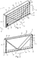
- the catalyst module 2 shown in Figure 1 comprises a peripheral stack frame 4, in the interior space of which a plurality of accurately fitting element boxes 6 are inserted.
- the element boxes 6 form a lattice structure or matrix structure.
- Each element box 6 has an accommodation, which is formed by a free interior space 8 of the respective element box 6.
- the element boxes 6 form a 12 x 5 matrix in the example.
- each of the element boxes 6 there are several catalysts 10, which are preferably constructed as monolithic honeycomb catalysts and fill the interior space 8 completely.
- catalysts 10 which are preferably constructed as monolithic honeycomb catalysts and fill the interior space 8 completely.
- Only one element box 6 is occupied by catalysts 10.
- only one catalyst 10 per element box 6 is used.
- the whole of the catalyst module 2 extends in the longitudinal direction 12 as well as in the transverse direction 14 and has two opposite open end faces 16, which are at a distance from one another in a direction of flow 18 by the length of a catalyst 10.
- the end faces 16 form an inflow or inlet side as well as an outlet side for the flue gas, which is to be cleaned and which flows through the installed catalyst module 2 in the direction of flow 18.
- the individual catalysts 10 are preferably extruded, rectangular honeycomb catalysts with a plurality of flow ducts extending in the direction of flow 18.
- the catalysts 10 preferably have a rectangular, especially a square cross-sectional and inflow surface, which has an edge length of 10 cm to 30 cm.
- four catalysts 10 are disposed in a 2 x 2 matrix in an element box 6.
- the element boxes 6 are therefore also formed square-shaped. Deviating from the square base shown, they may also be constructed with a rectangular base.
- the edge lengths of the element boxes may range from 0.4 m to 1 m.
- the length of the catalyst 10 in the direction of flow 18 typically ranges from a few 10 cm, for example from 15 cm to 60 cm.
- the width of the catalyst module in the direction of flow 18 corresponds at least approximately to the length of the catalysts 10.
- the total length of the catalyst module 2 in the length direction 12 and also in the transverse direction 14 typically is in the area of a few meters.
- a plurality of catalyst modules 2 are usually in rows and columns in a flue gas duct with the aid of a supporting frame.
- a layer of this type of catalyst modules 2 extends in the longitudinal direction 12 and in the transverse direction 14, in each case for example over from 10 m to 20 m. Usually, several such layers, consisting of several catalyst modules 2, then follow in the flow direction 18.
- the stack frame 4 has in total a peripheral wall consisting of four side frame parts, namely two side parts 20, a base part 22 as well as a lid part 24 (cf. Fig. 2 ).
- the four side frame parts 20, 22, 24 are connected with one another by means of bolted connections, for example, with the help of bolts 26 and, optionally, bolt nuts.
- the bolt nuts are fixed, for example welded, to the side frame parts 20 and the bolts 26 are then screwed into the nuts.
- the stack frame 4 has additional struts 28, which are also fastened at the edges by bolts 26 to the side parts 20 or to the base part 22 and there, preferably, in each case, to an edge part 29.
- Two struts 28, disposed approximately in the form of a V, are bolted to each end face 16.
- a sealing element 30 is also shown at the right-side part 20, which sealing element 30, in the Example, is formed, for example, from glass fibers as a mat-shaped nonwoven material.
- this sealing element 30 (with the exception of the missing, complete placement of catalysts 10) is pressed between the outer layer of the element boxes 6 and the right side part 20 as well as the lid part 24.
- a partial sealing element preferably is inserted once towards the side part 20 and once towards the lid part 24.
- the two partial sealing elements complement each other to form the sealing element 30.
- the sealing element 30 is thus also taken along the lid part 24 and, also at this longitudinal side, pressed between the outer layer of the element boxes 6 and the lid part 24.
- the sealing element 30 is a two-dimensional, strip-shaped element with a width, for example, of a few centimeters. Its width may also correspond at least approximately to the length of the element boxes 6 in the direction of flow 18. Its thickness lies, for example, in the region of one or a few centimeters. Sealing elements can likewise be inserted between adjacent element boxes 6.
- the side parts 20 as well as the base part 22 are constructed as hollow profiles consisting of sheet-metal parts, which are connected to one another, as is shown in particular in Figures 3 and 4 .
- the sheet-metal parts may be welded to one another.
- Both the side parts 40 and the base part 42 have a U-shaped part, preferably a sheet metal part 32a, and a planar part, preferably a sheet metal part 32b, which are connected to one another, for example by welding.
- the hollow profile is closed off by covers 34 or end caps. In each case, a hook, in particular a loop 36 is fastened to the cover 34 of the side parts 20.
- the loop 36 is used, for example, for lifting or for handling the whole of the catalyst module 2, for example, with the help of a crane. Furthermore, at least one strip 38 is fastened and especially welded along the U-shaped sheet metal part 32a as a polygonal pipe in particular. This holds a sealing element, which is not shown here and which, in the installed state, seals the stack frame 4 to a supporting frame in the flue gas duct of the emission control system.
- the sides of the U-shaped sheet metal part 32a are castellated at the ends and form protruding holding brackets 40.
- the holding brackets 40 are disposed in specified grid dimensions, which correspond especially to the width of an element box 6 in the longitudinal direction 12 or to a multiple hereof. As is evident particularly from Figure 1 , the holding brackets 40 are disposed so that they cover a joint between two adjacent element boxes 6. In the direction of flow 18, the holding brackets 40 are exactly opposite to one another and are spaced apart by the length of an element box 6, so that, in the flow direction 18, the latter is held between two holding brackets 40 assigned to one another.
- slots 42 through which the holding brackets 40 pass, are introduced, for example, by laser cutting also in the same grid dimensions in the flat sheet metal part 32b.
- the two sheet-metal parts 32a, b are therefore, as it were, interlocked with one another and, additionally, are preferably welded to one another.
- holding elements 44 such as brackets or the like, may be disposed for fastening (by bolts) the individual side frame parts 20 to 24 to one another (for this purpose, compare Figures 1, 2 ).
- nuts for example, are fixed at the side frame parts 20, especially at the side covers 34.
- the lid part 24 rests on the side frame parts 40.
- the flat sheet-metal parts 32b protrude on both sides over the sides of the U-shaped sheet metal part 32a in the direction of flow 18 in each case by an edge strip.
- the struts 28, for example, are fastened to this edge strip.
- the lid part 24 is constructed as a simple, U-shaped, bent metal sheet, wherein the protruding sides are oriented towards the outside, that is, averted from the element boxes 6. These protruding sides form sealing webs 46.
- the lid part 24 of the one catalyst module 2 accommodates the base part 22 of the adjacent catalyst module 2 between the two sealing webs 46, so that a parting plane between the two catalyst modules 2 is sealed.
- the stack frame 4 is formed as a whole by steel components, especially two-dimensional sheet-metal parts, the individual components having a wall thickness, for example, of mm to 10 mm.
- the side walls 50 of the element boxes 6 are also formed from steel sheet with a wall thickness, for example, of between 3 mm and 10 mm.
- each element box 6 has a peripheral side wall, which is formed by side walls 50 and forms the boundary of the free interior space 8. Additional partitions or struts or the like are not disposed within this free interior space 8. As shown particularly in Figures 6 and 8 , the individual catalysts 10 adjoin one another in this free interior space 8. Sealing strips 52, are inserted between mutually adjacent catalysts 10. These therefore extend horizontally in the example as well as vertically and, overall, as somewhat cross-shaped. These, like the sealing elements 30, are mats of nonwoven material for example.
- the sealing strips 52 and, preferably also, the sealing elements 30 consist in particular of a special nonwoven material, which has a coefficient of thermal expansion, which is comparable to that of the material (sheet-metal) of the element boxes 6. It consists of a nonwoven support material, into which a material with the desired coefficient of thermal expansion has been introduced. Such a material is, for example, a so-called vermiculite. Therefore, when there are temperature changes, for example, when the emission control system is started up, the sealing elements 30 exert a compressive force over the whole of the temperature range, so that they do not fall out of the element boxes 6.
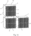
- plug-in brackets 54 as well as plug-in slots 56 are formed at each side wall 50, as can be seen in Figures 5 to 10 .
- the plug-in brackets 54 are formed by bending over partial regions of the side wall 50.
- the plug-in slots 56 are cut out, for example, with a laser.
- the plug-in brackets 54 as well as the plug-in slots 56 when viewed in the direction of flow 18, are formed at the opposite edge sides of a respective side wall 50.
- precisely one plug-in bracket 54 and one plug-in slot 56 are formed at each edge side.
- either plug-in brackets 54 or plug-in slots 56 are adjacent at the corners.
- bent-over region 58 At the end faces of the side walls 50, which end faces are opposite when viewed in the direction of flow 18, these end faces have a bent-over region 58. This serves for reinforcing the whole of the element box 6.
- the bent-over region 58 extends over the whole of the side length of a respective side wall 50. As can be inferred particularly from Figure 9 or also from Figure 5 , this bent-over region 58 is formed as a bevel, which is oriented at an angle with respect to the direction of flow 18.
- the bent-over region 58 rises, for example, at an angle of 30° to 45° from the outside to the free interior space 8.
- the catalyst module 2 is assembled preferably in the following way: Initially, the side frame parts 20, 22, 24 are provided and, if necessary, assembled to form the hollow profiles. Subsequently, at first only the left side part 20, as well as the base part 22 are bolted together to form an L-shaped partial frame. Alternatively, a U-shaped partial frame may also be provided.
- the element boxes 6, equipped previously with the catalysts 10, are inserted successively in this L frame. They are held preferably exclusively by the holding brackets 40 to the stack frame 4 and to one another preferably exclusively by the plug-in connections.
- the right-side part 20 is fastened to the L frame and, in so doing, the sealing element 30 is pressed between the outermost layer of the element boxes 6 and the right-side part 20.
- the sealing element especially a partial sealing element, is first fixed mechanically and especially by gluing here to the side part 20, before the side part 20 is then attached by bolting.
- the lid part 24 is then attached in the same way with compression of the sealing element 30.
- the sealing element 30 is thus pressed against the top layer of the element boxes 6 by bolting.
- the struts 28 are mounted. Therefore, by means of this manufacturing process, the individual element boxes 6 are clamped securely and reliably between the side frame parts 20, 22, 24. Since the sealing element 30 is clamped during the installation, it is compressed elastically over the whole surface thereof and clamped reliably.
Landscapes
- Engineering & Computer Science (AREA)
- Chemical & Material Sciences (AREA)
- Chemical Kinetics & Catalysis (AREA)
- General Engineering & Computer Science (AREA)
- Mechanical Engineering (AREA)
- Combustion & Propulsion (AREA)
- Health & Medical Sciences (AREA)
- Toxicology (AREA)
- Environmental & Geological Engineering (AREA)
- Materials Engineering (AREA)
- Organic Chemistry (AREA)
- Biomedical Technology (AREA)
- Analytical Chemistry (AREA)
- General Chemical & Material Sciences (AREA)
- Oil, Petroleum & Natural Gas (AREA)
- Exhaust Gas After Treatment (AREA)
- Exhaust Gas Treatment By Means Of Catalyst (AREA)
- Crystallography & Structural Chemistry (AREA)
- Catalysts (AREA)
Description
- The invention relates to a catalyst module for use in an emission control system of a stationary combustion system and a method for producing such a catalyst module.
- A stationary combustion system is understood to be any system for the combustion of hydrocarbon-based fuels. They are, for example, coal-fired or oil-fired (petroleum) systems or gas turbines. Stationary combustion systems also comprise marine applications, for example combustion systems such as diesel engines, as used for large container or cruise ships. The stationary combustion systems are usually operated continuously under a constant, stationary load.
- Stationary combustion systems usually have an emission control system, which is provided with catalyst modules. Moreover, the catalyst modules are installed in a flue gas duct of the emission control system and the flue gas, which is to be purified, flows through them during operation. In this connection, the flue gas duct typically has a cross-sectional area of at least several square meters and typically also of several times ten square meters. Frequently, the flue gas duct has a rectangular cross-section with an edge length in each case of several meters, for example, of 10 m x 10 m. The whole cross-sectional area of the flue gas duct is covered by one or also several catalyst modules, which are arranged next to one another, so that all the flue gas, which is to be purified, flows through the catalyst modules. Usually, several catalyst modules, for example, two to five, are disposed next to one another in rows and columns in a supporting framework within the flue gas duct. The catalyst modules themselves typically have a rectangular cross-section with an edge length of, in each case, several meters.
- Moreover, in the direction of flow of the flue gas, the catalyst modules frequently are disposed in several planes one behind the other. In the direction of flow, a catalyst installation, built up from catalyst modules, also extends for several meters, especially for several times ten of meters, such as for 25 m.
- The catalyst modules are built up from a stacking frame, in which several mounting units are inserted, which, in turn, are provided with several catalysts. Moreover, the flue gas flows through the individual catalysts in the direction of flow. These catalysts are, for example, plate catalysts. However, in the present case of interest, they are so-called honeycomb catalysts. These honeycomb catalysts are monolithic components of a ceramic material, which is permeated by a plurality of flow channels in the direction of flow. In the installed, operating state, flue gas, which is to be purified, flows through the flow channels. This monolithic structure has a catalytic activity with respect to purifying the flue gas. Alternatively, the monolithic carrier is provided with a catalytic coating or the carrier material itself is catalytically active. In particular, these honeycomb catalysts are extruded honeycomb catalysts. A catalyst typically has a rectangular and, in particular, a square cross-sectional surface with an edge length of about 10 cm to 30 cm.
- In a first variation, the mounting units are so-called element boxes, in which the individual catalysts are arranged in matrix fashion, adjoining one another. At the same time, sealing elements, which usually are in the form of a nonwoven fabric and are to prevent leakage flow through the boundary plane between adjacent catalysts or between the catalysts and the element boxes, are preferably disposed between the individual catalysts. Typically, moreover, two to ten catalysts with, in each case, a rectangular and, in particular, a square cross-sectional surface, are disposed usually in several layers over or next to one another in a respective element box.
- The element boxes themselves are disposed within the stack frame also in matrix fashion. The number of element boxes depends on the size of the catalyst module. The element boxes are usually constructed from sheet-metal parts, which, for reinforcing purposes, have edges, which are folded over about 90° at opposite sides. In operation, these are therefore oriented perpendicularly to the direction of flow of the flue gas, which is to be purified, and, with that, form surfaces, which undesirably resist flow.
- Aside from the element boxes, which typically are disposed in several rows in a stack frame, the mounting units of a second variation are constructed as so-called packing and storage units, which, in each case, are also provided with catalysts; in comparison to element boxes, they are larger and are typically arranged only in a single row within a catalyst module. Usually, sealing and compensating elements of a nonwoven fabric are in turn disposed between the catalysts.
- In the emission control system, the catalyst modules are fastened to one another with the help of the stack frame. The catalyst modules are prefabricated as construction units, usually, for example, by the manufacturer of the catalysts, and installed as such. During the operation, the catalyst modules must withstand mechanical as well as thermal loads. The temperature of the flue gas in such stationary installations typically ranges from, for example, 400° to 500°. With regard to as effective a purification of the flue gas as possible, leakage flows should be avoided so that the whole of the flue gas passes by the catalytically active surfaces. With regard to the minimization of flow pressure losses, it is also desirable to utilize the largest possible proportion of the cross-sectional area of the flue gas duct.
- The stack frame of the prior art is a welded steel profile, in which the individual mounting units, that is, for example, the element boxes or also the packing and storage units, are inserted. In order to achieve secure mechanical fastening, the element boxes are each welded to the stack frame as well as to one another. In order to be able to equip the stack frame, the latter is over-dimensioned to some degree. The remaining gap is sealed with a strip-shaped sealing element. However, the problem exists here that, because of different thermal coefficients of expansion, this strip-shaped sealing element may become detached in operation, so that leakage flows result. This problem affects also the sealing and equalization elements inserted between the individual catalysts. Overall, the danger therefore exists in the case of conventional units that, in the course of the operating time, leakage flows will result. Arrangements with packing and storage units, in which, for example, in each case three such units per catalyst module are strung together, are welded together and to the stack frame these days in a costly pressing and welding device, which is especially manufactured for this purpose. For providing it with catalysts, a packing and storage unit initially is inserted in an open frame of the unit, after which the packing and storage units are braced against one another by pressing on a lid. Subsequently, the lid is welded to the side parts of the packing and storage unit. These packing and storage units are then, in turn, placed in the stack frame, to which they are welded. Here also, it is necessary once again to seal. Because of this complex manufacturing process, an expensive welding device is required and typically also matched to the size of the respective catalyst module. As a result, the total manufacturing costs are comparatively high.
-
JP 58024323A -
JP 62191026A -
US 4,238,455 A discloses a denitrification reactor wherein each catalyst cell is provided by packing a plurality of honeycomb catalyst blocks into a box-shaped frame with four corner posts; a plurality of vertical guide posts are erected in such a spaced apart relationship that four adjacent vertical guide posts may vertically guide the corner posts of each catalyst cell; and the catalyst cells with honeycomb catalyst blocks are charged along said vertical guide posts and are pressed thereagainst. - Starting out from the above, it is an object of the invention to enable a simplified production of such a catalyst module, which, in particular, has at the same time continuously good flow properties and an improved cleaning efficiency because of less leakage.
- The objective is accomplished in accordance with the invention by a catalyst module for use in an emission control system of an industrial scale combustion system. The catalyst module is therefore designed and conceived for such previously described emission control systems of stationary combustion systems, especially of power plants for generating energy. Reference is made to the previous versions with respect to the basic arrangement as well as with respect to the basic construction and the size relationships of such catalyst modules.
- The catalyst module comprises a stack frame, which extends in a longitudinal direction as well as in a transverse direction and has two end surfaces, which are opposite to one another in a direction of flow, several mounting units inserted in the stack frame and adjoining one another, each constructed as an element box in the form of a n x m matrix and having peripheral side walls, wherein each of the element boxes form the boundary of a free interior space containing several catalysts, wherein the element boxes are held together positively without being fastened by welding by co-operation of respective at least one plug-in connections and at least one plug-in openings formed at the side walls, wherein one plug-in element as well as one plug-in opening is formed in each side wall at the edge in the direction of the end faces, the stack frame comprising a peripheral wall, which is assembled from side frame parts, which are connected and especially bolted to one another via at least one mechanical connecting element and an elastic, mat-shaped sealing element of non-woven material arranged, in a compressed state, between at least one of the side frame parts and at least one mounting unit.
- The stack frame has a base part and a lid part as well as two side parts. The stack frame extends in a longitudinal as well as in a transverse direction and has two opposite end surfaces in a flow direction, which end surfaces are bordered by the base part, the lid part and the two side parts. The end surfaces are braced in the longitudinal direction and the transverse direction and are oriented perpendicularly to the direction of flow of a flue gas, when they are installed in a flue gas duct of the emission control system. At least one, preferably several mounting units, which each have a peripheral side wall and each are open in the direction of the end face, are inserted in this stack frame. Each of these mounting units is provided with several catalysts, especially with honeycomb catalysts.
- The catalysts are preferably monolithic honeycomb catalysts comprising a ceramic carrier material which is penetrated by a multiplicity of individual flow ducts. Here, the carrier material is optionally coated with a catalytically active layer or is itself catalytically active. A catalyst is generally understood to be a unit with a catalytic activity for the desired purification of the flue gas. Aside from (extruded) honeycomb catalysts, plate catalysts may, for example, also be used. The catalysts in a catalyst module are preferably but not necessarily of identical configuration to one another. Here, a plurality of catalyst part units, that is to say, for example, a plurality of monolithic honeycomb bodies, can also be inserted one after another in the direction of flow. These part units which are lined up in a row in the direction of flow then form one catalyst. If required, the part units are of different configuration with regard to their catalytic action. They are preferably of identical configuration.
- The stack frame furthermore has a peripheral wall, which is composed of individual side frame parts, which are connected and especially bolted to one another by at least one, preferably several mechanical connecting elements. The side frame parts are not welded together. Preferably, they are therefore connected exclusively by mechanical connecting elements, especially by bolts. Furthermore, at least one sealing element is pressed between at least one side frame part and an adjoining mounting unit and, moreover, because of a bracing of the one side frame part, during the installation thereof with bolts. During the manufacture, the at least one sealing element is therefore initially placed on one of the mounting units at the edge, before the adjoining side frame part is bolted to the further side frame parts. The sealing element is pressed here between the side frame part and the at least one mounting part with the help of the mechanical connecting element. At the same time, the pressing force is applied by the mechanical connecting element. All the mounting units are clamped into the stack frame by these means.
- The mechanical connecting elements preferably are bolting elements, such as bolts with the nuts, threaded bolts, etc.
- The special advantage is achieved by such a procedure that, by the bolting of the side frame parts, the sealing element is firmly pressed between at least one side frame part and the at least one mounting unit and thus compressed because of its elastic properties. As a result, variations in the distance between the side frame parts and the mounting units are equalized even if the thermal expansion of the individual components is different. If there is a change in temperature, for example, between the installation and the operation or also when the combustion system is started up, the sealing element is prevented by these means from falling out and, with that, the occurrence of leakage flows is avoided reliably.
- "Elastic sealing element" is first of all generally to be understood to be any element which exhibits an elasticity and ensures a sealing action in the long term between the respective mounting unit and the respective side frame part, even at the high operating temperatures of several hundred degrees Celsius and, in particular, even in the case of temperature changes, for example while running the system up or down. Here, "elastic" is generally understood to mean that a deformation of the sealing element, for example a change in the thickness of more than 10%, for example of from 10% to 30%, is possible while retaining an (elastic) restoring force, with the result that the fitting element is held preferably but not necessarily held between the wall of the mounting shaft and the side frame part solely by way of the elastic restoring force. In principle, sealing elements can also be inserted between each of the mounting units and a side frame part.
- Due to the bolted arrangement, there is, at the same time, no need for a pressing and welding facility. By these means, the individual catalyst modules can therefore be adapted without problems, for example, with regard to their size, flexibly to the respective application i.e. the concrete installation situation in a plant. With that, the total manufacturing costs are kept low. Due to the arrangement with the bolting of the side frame parts, assembling directly at the building site is also simplified. Until now, the catalyst modules were prefabricated at a production site and moved as prefabricated units to the building site or the place of use. During this transport, special measures are also required in order to prevent sealing elements falling out or also other damage occurring to the individual ceramic catalysts, which usually are fragile.
- With regard to manufacturing the stack frame as simply and as cost effectively as possible, the side frame parts thereof preferably are formed at least partly from sheet metal parts, which have been bent over. For forming the side frame parts, U-shaped profiles, for example, are preferably formed from initially flat metal sheets by bending edge parts and are formed by a further metal sheet element into a closed polygon. By these means, a sufficiently high stability is achieved with a comparatively low use of material. In combination with the arrangement that can be bolted, this also leads to the fact that the individual side frame parts can be transported in a space-saving manner as individual elements. In this connection, the respective side frame part is formed by an elongated, flat element.
- Expediently, the side frame parts are constructed in each case as a hollow profile of two sheet metal parts, which are connected with one another. At least one of these sheet-metal parts is bent over and forms, for example, a U-shaped profile, on which then the second sheet-metal part is placed as if it were a lid. To connect them, these two sheet-metal parts interlock positively with one another in particular via brackets and slots, so that a high mechanical stability is attained.
- In a preferred arrangement, at least some and preferably all of the side frame parts have retaining brackets, between which a respective mounting unit is held positively in the direction of flow. By these means, the mounting units are additionally secured mechanically within the side frame part. Welding of the mounting units to the side frame parts is foregone and these units are exclusively held positively by the holding brackets. The mounting units are therefore fixed in the direction of flow by the holding brackets. The holding brackets are preferably arranged on both sides of the mounting units as viewed in the direction of flow.
- Expediently, one of the side frame parts is constructed as a lid part and, externally, has at least one sealing web, which is disposed at the edge and preferably is formed by bending over the side frame part. The function of the sealing web is to close off a parting plane between two adjacent catalysts modules in the installed state. Preferably, the lid part as a whole is bent over in a U-shaped manner, so that such a sealing web is formed as a fold on either side of the longitudinal edges of the lid part. An adjacent catalyst module with a base element is accommodated between these sealing webs as viewed in the direction of flow.
- The mounting units are so-called element boxes, which were described above. In this respect, reference is made to the introductory embodiments of the basic construction as well as the basic arrangement of such element boxes within the stack frame. Several element boxes, forming an n x m matrix and adjoining one another, are inserted in several rows and columns within the stack frame. The element boxes are therefore disposed in n rows above one another and in m columns next to one another. Each of the element boxes has a free interior space, in which several catalysts, adjacent to one another, are inserted. In this connection, a free interior space is understood to mean that the element boxes do not have any additional internal partitions. The element boxes are therefore formed by peripheral side walls and are open towards the opposite end faces of the stack frame. The wall consists especially of one or several metal sheets, which are connected with one another. Usually, sealing elements are inserted between the catalysts.
- A further advantage is to be seen therein that the individual catalysts are exposed now only to lower pressing forces during the assembly of the stack frame. In comparison to previous solutions, the catalysts need therefore only be formed now with a lesser mechanical stiffness. This has a favorable effect on the flow properties of the catalyst, especially the honeycomb catalyst, so that an improved cleaning efficiency is also achieved by these means.
- The use of the sealing elements at the same time also provides a means which insulates the catalyst against forces which are caused by temperature changes during heating up and contact with the walls which surround it, or against vibrations or jolts which can occur during normal operation and act on the catalyst. This makes it possible to use catalysts which are weaker in terms of their structure than those currently in use. At the same time, advantages such as reduced back-pressure, etc. are associated with this, since, on account of the insulating properties, they certainly do not have to have the strength exhibited by conventional catalysts.
- According to the invention, the element boxes are held together positively by means of plug-in connections, without being fastened further by welding. The element boxes have complementary plug-in connection elements, with the result that they are held by being simply plugged in or on. Therefore, a largely or completely weld-free assembly of the catalyst module is supported by this special arrangement of the element boxes as components which can be plugged into one another. The individual element boxes are held together positively and therefore fixed to one another only by the plug-in connections. Especially in conjunction with the boltable stack frame, the resulting assembly is simple. In particular, the stack frame is assembled only partly initially, in particular the base part is initially only constructed with one or both side frame parts, so that an open L- or U-shaped stack frame is formed which is then provided successively with the element boxes, before it is then closed by the lid part.
- At the side walls, there is at least one plug-in element and one plug-in opening for forming the plug-in connections. These are formed, especially as a plug-in bracket, which preferably is bent, and as a plug-in slot.
- In an expedient further development, the element boxes are held positively not only to one another but also to the stack frame and, in particular, without being fastened further by welding. For this purpose, for example, a plug-in bracket engages in a corresponding mounting in the stack frame, which, preferably, has appropriate mountings in its side frame parts. Alternatively, or in addition, the element boxes are held by the already mentioned bent holding brackets at the respective side frame part.
- Overall, due to this concept, a weld-free construction of the individual element boxes within the stack frame in the form of a clip-in or plug-in system is attained, by means of which the manufacturing costs as a whole are kept low.
- This basic concept of element boxes, which are connected positively with one another in the form of a clip-in or plug-in system, basically is possible also independently of the bolted arrangement of the stack frame with the pressed-in sealing element and is regarded as an independent, inventive concept. The right to submit divisional applications for this is retained.
- With regard to an improved through-flow of the individual catalysts, the edges of the side walls of the element boxes have a bent-over region, which is oriented at an angle to the direction of flow, at one end face in such a manner, that the bent-over region rises from the outer boundary of the element box inwards towards the catalyst. These bent-over regions are preferably configured on the inflow side and, in particular, on both end faces which lie opposite one another. An advantageous guidance of the flow, without dammed areas, is achieved by these means, as is the case with known element boxes, in which 90° bent-over portions are usually configured on the end faces. This is advantageous particularly on the end face, which forms an inlet side for the flue gas. This is advantageous also on the opposite end face, which forms an outflow side, with regard to a largely turbulent-free flow.
- Preferably, a vertical section adjoins the bent-over area and is oriented at an angle to the latter. A respective end edge is therefore bent over at least twice at least in regions. The mechanical stiffness is increased by these means. In addition, in a preferred arrangement, the vertical section in at least a partial region is passed into or through the side wall. It is therefore supported, in particular, in the side wall, which likewise leads to improved rigidity. Preferably, the vertical section is passed through the side wall and protrudes over the latter, especially for forming the plug-in bracket. A plug-in bracket therefore is a continuation of the bent-over area.
- The mounting unit for use in the catalyst module according to the invention can be formed as an element box with a free interior space, the element box forming, at its side walls, at least one plug-in element, especially a plug-in bracket, as well as a plug-in opening, especially a plug-in slot, so that adjoining element boxes are held together by plug-in brackets and plug-in slots in the form of a plug-in system.
- Furthermore, the objective of the invention with respect to the method is accomplished by a method for producing a catalyst module according to the invention, for which several mounting units are provided, each containing at least one catalyst, each mounting unit being constructed as an element box in the form of a n x m matrix and having peripheral side walls, wherein each of the element boxes forms a boundary of a free interior space containing the catalysts, wherein the element boxes are held together positively without being fastened by welding by co-operation of respective at least one plug-in connections and at least one plug-in openings formed at the side walls, wherein one plug-in element as well as one plug-in opening is formed in each side wall at the edge in the direction of the end faces, the stack frame is assembled only partly in a first step, the mounting units are inserted in the stack frame, which has been assembled only partly, an elastic, mat-shaped sealing element of non-woven material is placed down and the stack frame is closed with the help of a mechanical connecting element with compression of the sealing element between a side frame part of the stack frame and at least one of the mounting units.. Here, "partly assembled" is understood to mean that the stack frame is first of all open on at least one side, with the result that the mounting units can be inserted via this open side.
- Especially a mat-shaped sealing element, particularly a non-woven mat, is then placed on the last layer of the mounting units. Subsequently, the stack frame is closed with compression of the sealing element. The sealing element is pressed here between a side frame part of the stack frame and at least one of the mounting units. Generally, preferably, the sealing element rests with its entire surface on the mounting units.
- The sealing element is substantially a flat, plate-shaped or strip-shaped and overall rectangular element which is configured in terms of area with a preferably rectangular basic area and is introduced between the mounting units and the respective side frame part.
- Alternatively, to the element boxes described here, the mounting units may also comprise differently configured mounting units. The use of the element boxes which are described here is not absolutely necessary.
- Preferably, the stack frame initially is built up L-shaped and the sealing element is subsequently placed in L-shaped fashion on the outer layer of the mounting units, before the stack frame is closed with compression of the sealing element.
- An example of the invention is explained in greater detail in the following by means of the Figures, in which
- Figure 1
- shows a perspective representation of a partially equipped catalyst module,
- Figure 2
- shows a perspective representation of an assembled stack frame,
- Figure 3
- shows a first side frame part of the stack frame in an exploded representation,
- Figure 4
- shows a second side frame part, also in an exploded representation
- Figure 5
- shows an enlarged representation of the partial area of
Figure 1 , which is marked with a rectangle, - Figure 6
- shows a perspective view of an element box,
- Figure 7
- shows an end face view of the element box of
Figure 6 , - Figure 8
- shows a sectional view through the element boxes of
Figure 6 along the section A-A inFigure 7 , - Figure 9
- shows an enlarged representation of the corner region, which is marked with a circle in
Figure 8 and - Figure 10
- shows a perspective representation of several element boxes to illustrate the assembly of the element boxes in the form of a plug-in system.
- In the Figures, identical components have been provided with identical reference numbers.
- The catalyst module 2, shown in
Figure 1 , comprises aperipheral stack frame 4, in the interior space of which a plurality of accuratelyfitting element boxes 6 are inserted. Theelement boxes 6 form a lattice structure or matrix structure. Eachelement box 6 has an accommodation, which is formed by a free interior space 8 of therespective element box 6. Within thestack frame 4, several rows as well as several columns ofelement boxes 6 are usually disposed. Theelement boxes 6 form a 12 x 5 matrix in the example. - In each of the
element boxes 6, there areseveral catalysts 10, which are preferably constructed as monolithic honeycomb catalysts and fill the interior space 8 completely. InFigure 1 , only oneelement box 6 is occupied bycatalysts 10. As an alternative, only onecatalyst 10 perelement box 6 is used. - The whole of the catalyst module 2 extends in the
longitudinal direction 12 as well as in thetransverse direction 14 and has two opposite open end faces 16, which are at a distance from one another in a direction offlow 18 by the length of acatalyst 10. The end faces 16 form an inflow or inlet side as well as an outlet side for the flue gas, which is to be cleaned and which flows through the installed catalyst module 2 in the direction offlow 18. - The
individual catalysts 10 are preferably extruded, rectangular honeycomb catalysts with a plurality of flow ducts extending in the direction offlow 18. Thecatalysts 10 preferably have a rectangular, especially a square cross-sectional and inflow surface, which has an edge length of 10 cm to 30 cm. In the example, fourcatalysts 10 are disposed in a 2 x 2 matrix in anelement box 6. Theelement boxes 6 are therefore also formed square-shaped. Deviating from the square base shown, they may also be constructed with a rectangular base. Typically, the edge lengths of the element boxes may range from 0.4 m to 1 m. The length of thecatalyst 10 in the direction offlow 18 typically ranges from a few 10 cm, for example from 15 cm to 60 cm. The width of the catalyst module in the direction offlow 18 corresponds at least approximately to the length of thecatalysts 10. - The total length of the catalyst module 2 in the
length direction 12 and also in thetransverse direction 14 typically is in the area of a few meters. A plurality of catalyst modules 2 are usually in rows and columns in a flue gas duct with the aid of a supporting frame. A layer of this type of catalyst modules 2 extends in thelongitudinal direction 12 and in thetransverse direction 14, in each case for example over from 10 m to 20 m. Usually, several such layers, consisting of several catalyst modules 2, then follow in theflow direction 18. - The
stack frame 4 has in total a peripheral wall consisting of four side frame parts, namely twoside parts 20, abase part 22 as well as a lid part 24 (cf.Fig. 2 ). The fourside frame parts bolts 26 and, optionally, bolt nuts. For example, the bolt nuts are fixed, for example welded, to theside frame parts 20 and thebolts 26 are then screwed into the nuts. Alternatively, it is also possible to provide fixed threaded bolts, onto which the nuts are then placed. A welded connection between these parts is foregone. To increase the stiffness, thestack frame 4 hasadditional struts 28, which are also fastened at the edges bybolts 26 to theside parts 20 or to thebase part 22 and there, preferably, in each case, to anedge part 29. Two struts 28, disposed approximately in the form of a V, are bolted to eachend face 16. - In
Figure 2 , a sealingelement 30 is also shown at the right-side part 20, which sealingelement 30, in the Example, is formed, for example, from glass fibers as a mat-shaped nonwoven material. In the final, installed state, as shown inFigure 1 , this sealing element 30 (with the exception of the missing, complete placement of catalysts 10) is pressed between the outer layer of theelement boxes 6 and theright side part 20 as well as thelid part 24. In this connection, a partial sealing element preferably is inserted once towards theside part 20 and once towards thelid part 24. The two partial sealing elements complement each other to form the sealingelement 30. The sealingelement 30 is thus also taken along thelid part 24 and, also at this longitudinal side, pressed between the outer layer of theelement boxes 6 and thelid part 24. In particular, the sealingelement 30 is a two-dimensional, strip-shaped element with a width, for example, of a few centimeters. Its width may also correspond at least approximately to the length of theelement boxes 6 in the direction offlow 18. Its thickness lies, for example, in the region of one or a few centimeters. Sealing elements can likewise be inserted betweenadjacent element boxes 6. - In the example, the
side parts 20 as well as thebase part 22 are constructed as hollow profiles consisting of sheet-metal parts, which are connected to one another, as is shown in particular inFigures 3 and 4 . The sheet-metal parts may be welded to one another. Both theside parts 40 and thebase part 42 have a U-shaped part, preferably asheet metal part 32a, and a planar part, preferably asheet metal part 32b, which are connected to one another, for example by welding. At the sides, the hollow profile is closed off bycovers 34 or end caps. In each case, a hook, in particular aloop 36 is fastened to thecover 34 of theside parts 20. Theloop 36 is used, for example, for lifting or for handling the whole of the catalyst module 2, for example, with the help of a crane. Furthermore, at least onestrip 38 is fastened and especially welded along the U-shapedsheet metal part 32a as a polygonal pipe in particular. This holds a sealing element, which is not shown here and which, in the installed state, seals thestack frame 4 to a supporting frame in the flue gas duct of the emission control system. - The sides of the U-shaped
sheet metal part 32a are castellated at the ends and form protruding holdingbrackets 40. The holdingbrackets 40 are disposed in specified grid dimensions, which correspond especially to the width of anelement box 6 in thelongitudinal direction 12 or to a multiple hereof. As is evident particularly fromFigure 1 , the holdingbrackets 40 are disposed so that they cover a joint between twoadjacent element boxes 6. In the direction offlow 18, the holdingbrackets 40 are exactly opposite to one another and are spaced apart by the length of anelement box 6, so that, in theflow direction 18, the latter is held between two holdingbrackets 40 assigned to one another. - Corresponding to the holding
brackets 40,slots 42, through which the holdingbrackets 40 pass, are introduced, for example, by laser cutting also in the same grid dimensions in the flatsheet metal part 32b. The two sheet-metal parts 32a, b are therefore, as it were, interlocked with one another and, additionally, are preferably welded to one another. Additionally, holdingelements 44, such as brackets or the like, may be disposed for fastening (by bolts) the individualside frame parts 20 to 24 to one another (for this purpose, compareFigures 1, 2 ). Alternatively, or in addition, nuts, for example, are fixed at theside frame parts 20, especially at the side covers 34. Thelid part 24 rests on theside frame parts 40. - The flat sheet-
metal parts 32b protrude on both sides over the sides of the U-shapedsheet metal part 32a in the direction offlow 18 in each case by an edge strip. Thestruts 28, for example, are fastened to this edge strip. - In contrast to the
side parts 20 and thebase part 22, thelid part 24 is constructed as a simple, U-shaped, bent metal sheet, wherein the protruding sides are oriented towards the outside, that is, averted from theelement boxes 6. These protruding sides form sealingwebs 46. When several catalyst modules 2 are strung together in thetransverse direction 14, thelid part 24 of the one catalyst module 2 accommodates thebase part 22 of the adjacent catalyst module 2 between the two sealingwebs 46, so that a parting plane between the two catalyst modules 2 is sealed. - The
stack frame 4 is formed as a whole by steel components, especially two-dimensional sheet-metal parts, the individual components having a wall thickness, for example, of mm to 10 mm. Theside walls 50 of theelement boxes 6 are also formed from steel sheet with a wall thickness, for example, of between 3 mm and 10 mm. - The construction of each
element box 6 is evident especially fromFigures 6 to 10 , as well as, in addition, also fromFigure 5 . Theelement box 6 has a peripheral side wall, which is formed byside walls 50 and forms the boundary of the free interior space 8. Additional partitions or struts or the like are not disposed within this free interior space 8. As shown particularly inFigures 6 and 8 , theindividual catalysts 10 adjoin one another in this free interior space 8. Sealing strips 52, are inserted between mutuallyadjacent catalysts 10. These therefore extend horizontally in the example as well as vertically and, overall, as somewhat cross-shaped. These, like the sealingelements 30, are mats of nonwoven material for example. Their function is to protect theindividual catalysts 10 mechanically and to seal a gap between thecatalysts 10 and, if necessary, between thecatalysts 10 and theside walls 50. The sealing strips 52 and, preferably also, the sealingelements 30 consist in particular of a special nonwoven material, which has a coefficient of thermal expansion, which is comparable to that of the material (sheet-metal) of theelement boxes 6. It consists of a nonwoven support material, into which a material with the desired coefficient of thermal expansion has been introduced. Such a material is, for example, a so-called vermiculite. Therefore, when there are temperature changes, for example, when the emission control system is started up, the sealingelements 30 exert a compressive force over the whole of the temperature range, so that they do not fall out of theelement boxes 6. - In the example, plug-in
brackets 54 as well as plug-inslots 56 are formed at eachside wall 50, as can be seen inFigures 5 to 10 . The plug-inbrackets 54 are formed by bending over partial regions of theside wall 50. The plug-inslots 56 are cut out, for example, with a laser. In the example, the plug-inbrackets 54 as well as the plug-inslots 56, when viewed in the direction offlow 18, are formed at the opposite edge sides of arespective side wall 50. In the example, precisely one plug-inbracket 54 and one plug-inslot 56 are formed at each edge side. In the Example, at mutuallyadjacent side walls 50, either plug-inbrackets 54 or plug-inslots 56 are adjacent at the corners. In other words, this means that, when viewed in the direction offlow 18, as shown, for example, inFigure 8 , the plug-inbrackets 54 as well as the plug-inslots 56 atopposite side walls 50 in each case are diagonally opposite to one another. By these means, a quasi-upper side and a quasi-underside, as well as a left and right side of theelement box 6 are defined. - Mutually
adjacent element boxes 6 are simply inserted into thestack frame 4 in an easy to assemble manner by stringing them together or placing them on top of one another. As a result, the plug-inbrackets 54 engage in the plug-inslots 56, so that theelement boxes 6 are connected positively with one another, the positive connection acting in the direction offlow 18. Theindividual element boxes 6 therefore form a plug-in system and can simply be inserted into one another. Theelement boxes 6 are securely fixed mechanically to one another by these plug-in connections, and are not fixed in any other way, especially not by welding. - At the end faces of the
side walls 50, which end faces are opposite when viewed in the direction offlow 18, these end faces have a bent-overregion 58. This serves for reinforcing the whole of theelement box 6. The bent-overregion 58 extends over the whole of the side length of arespective side wall 50. As can be inferred particularly fromFigure 9 or also fromFigure 5 , this bent-overregion 58 is formed as a bevel, which is oriented at an angle with respect to the direction offlow 18. The bent-overregion 58 rises, for example, at an angle of 30° to 45° from the outside to the free interior space 8. - Additionally, a vertical section, which forms the plug-in
bracket 54 and passes through theside wall 50, is also connected to the bent-overregion 58. This situation can also be seen especially inFigure 5 - The catalyst module 2 is assembled preferably in the following way:
Initially, theside frame parts left side part 20, as well as thebase part 22 are bolted together to form an L-shaped partial frame. Alternatively, a U-shaped partial frame may also be provided. Theelement boxes 6, equipped previously with thecatalysts 10, are inserted successively in this L frame. They are held preferably exclusively by the holdingbrackets 40 to thestack frame 4 and to one another preferably exclusively by the plug-in connections. After theelement boxes 6 are loaded, initially the right-side part 20 is fastened to the L frame and, in so doing, the sealingelement 30 is pressed between the outermost layer of theelement boxes 6 and the right-side part 20. The sealing element, especially a partial sealing element, is first fixed mechanically and especially by gluing here to theside part 20, before theside part 20 is then attached by bolting. Thelid part 24 is then attached in the same way with compression of the sealingelement 30. The sealingelement 30 is thus pressed against the top layer of theelement boxes 6 by bolting. Finally, at the end, thestruts 28 are mounted. Therefore, by means of this manufacturing process, theindividual element boxes 6 are clamped securely and reliably between theside frame parts element 30 is clamped during the installation, it is compressed elastically over the whole surface thereof and clamped reliably. - As a result of the construction described here and the special method of assembling the catalyst module, especially the following advantages are achieved:
- A complex pressing device or welding equipment is not required for filling the
stack frame 4 with theelement boxes 6. A leak-free sealing and assembly is made possible by inserting the sealingelement 30. - Horizontal sealing in the
transverse direction 14 is accomplished easily by thelid parts 24, which are bent in U-shaped fashion. - Because the welded connections of the
element boxes 6 to one another and between theelement boxes 6 and thestack frame 4 are omitted, appreciable time is saved during the assembly. This also leads to appreciable reductions in cost, especially because no welding or pressing equipment is required. - Furthermore, because of the modular concept, which is described here, with the bolted
side frame parts - The use of the
element boxes 6, in particular also in combination with sealingelements 30, at the same time also provides a means which insulates thecatalysts 10 against forces which are caused by temperature changes during heating up and contact with other parts of the catalyst module 2, or against vibrations or jolts which can occur during normal operation and act on thecatalysts 10. The catalyst module 2 makes it possible to usecatalysts 10 which are weaker in terms of their structure than those currently in use. At the same time, advantages such as reduced back-pressure, etc. are associated with this, since, on account of the insulating properties, the catalysts certainly do not have to have the strength exhibited by conventional catalysts. - Finally, there is also an improved flow guidance, especially because of the inclined, bent-over
regions 58. -
- 2
- catalyst module
- 4
- stack frame
- 6
- element box
- 8
- free internal space
- 10
- catalyst
- 12
- longitudinal direction
- 14
- transverse direction
- 16
- end faces
- 18
- direction of flow
- 20
- side part
- 22
- base part
- 24
- lid part
- 26
- bolted connection
- 28
- struts
- 29
- edge part
- 30
- sealing element
- 32a
- U-shaped sheet metal part
- 32b
- flat sheet metal part
- 34
- cover
- 36
- loop
- 38
- strip
- 40
- holding bracket
- 42
- slot
- 44
- holding element
- 46
- sealing web
- 50
- side wall
- 52
- sealing strip
- 54
- plug-in bracket
- 56
- plug-in slot
- 58
- bent-over region
Claims (12)
- A catalyst module (2) for use in an emission control system of an industrial scale combustion system- comprising a stack frame (4), which extends in a longitudinal direction (12) as well as in a transverse direction (14) and has two end surfaces (16), which are opposite to one another in a direction of flow (18),- several mounting units inserted in the stack frame (4) and adjoining one another, each constructed as an element box (6) in the form of a n x m matrix and having peripheral side walls (50), wherein each of the element boxes (6) form the boundary of a free interior space containing several catalysts (10), wherein the element boxes (6) are held together positively without being fastened by welding by co-operation of respective at least one plug-in connections (54) and at least one plug-in openings (56) formed at the side walls (50), wherein one plug-in element (54) as well as one plug-in opening (56) is formed in each side wall (50) at the edge in the direction of the end faces (16),- the stack frame (4) comprising a peripheral wall, which is assembled from side frame parts (20, 22, 24), which are connected and especially bolted to one another via at least one mechanical connecting element (26) and- an elastic, mat-shaped sealing element (30) of non-woven material arranged, in a compressed state, between at least one of the side frame parts (20, 24) and at least one mounting unit (6).
- The catalyst module (2) of claim 1, for which the side frame parts (20, 22, 24) have bent-over sheet-metal parts (32a, 32b).
- The catalyst module (2) of claim 1 or 2, for which the side frame parts (20,22,24) are constructed in each case as a hollow profile of two sheet-metal parts (32a, 32b), which are connected with one another.
- The catalyst module (2) of one of the preceding claims, for which at least some of the side frame parts (20, 22, 24) have holding brackets (40), between which a mounting unit (6) is held.
- The catalyst module (2) of one of the preceding claims, for which one of the side frame parts is constructed as a lid part (24) and, externally, has at least one sealing web (46), which is disposed at the edge and is formed, especially, by bending over, wherein the sealing web (46) is constructed for closing a parting plane between two adjacent catalyst modules (2) in the installed state.
- The catalyst module according to any preceding claim, wherein the elastic, mat-shaped sealing element (30) of non-woven material is formed from glass fibers or vermiculite.
- The catalyst module (2) of any preceding claim, for which those element boxes (6), which are in contact with the stack frame (4), are held positively at the latter, especially without being fastened by welding.
- The catalyst module (2) of any preceding claim, for which the side walls (50) consist of metal sheets (32a, 32b), which, at the edge of at least one of the two end faces (16), have a bent-over region, which is oriented at an angle to the direction of flow (18).
- The catalyst module (2) of claim 7 and 1, for which the bent-over region (58) adjoins a beveled vertical section, which is passed through the side wall (50) and protrudes over the latter especially for forming the plug-in element (54).
- A catalyst module (2) of one of the preceding claims, wherein the mounting units (6) are constructed as an element box (6), which has a free interior space (8) for accommodating at least one catalyst (10) and also has side walls (50), at which at least one plug-in element (54) as well as a plug-in opening (56) is formed, so that mutually adjoining element boxes (6) are held positively to one another by the plug-in elements (54) and the plug-in openings (56).
- A method for producing a catalyst module (2) of one of the claims 1 to 10, for which- several mounting units are provided, each containing at least one catalyst (10), each mounting unit being constructed as an element box (6) in the form of a n x m matrix and having peripheral side walls (50), wherein each of the element boxes (6) forms a boundary of a free interior space containing the catalysts (10), wherein the element boxes (6) are held together positively without being fastened by welding by co-operation of respective at least one plug-in connections (54) and at least one plug-in openings (56) formed at the side walls (50), wherein one plug-in element (54) as well as one plug-in opening (56) is formed in each side wall (50) at the edge in the direction of the end faces (16),- the stack frame (4) is assembled only partly in a first step,- the mounting units (6) are inserted in the stack frame (4), which has been assembled only partly,- an elastic, mat-shaped sealing element (30) of non-woven material is placed down and- the stack frame (4) is closed with the help of a mechanical connecting element (26) with compression of the sealing element (30) between a side frame part of the stack frame (4) and at least one of the mounting units.
- The method of claim 11, for which the stack frame (4) initially is constructed L-shaped and, subsequently, the sealing element is placed down L-shaped before the stack frame (4) is closed with compression of the sealing element (30).
Applications Claiming Priority (2)
| Application Number | Priority Date | Filing Date | Title |
|---|---|---|---|
| DE102014203618.6A DE102014203618A1 (en) | 2014-02-27 | 2014-02-27 | Catalyst module, receiving unit for such a catalyst module and method for producing such a catalyst module |
| PCT/GB2015/050563 WO2015128658A1 (en) | 2014-02-27 | 2015-02-26 | Catalyst module, receiving unit for such a catalyst module and method for manufacturing such a catalyst module |
Publications (2)
| Publication Number | Publication Date |
|---|---|
| EP3111068A1 EP3111068A1 (en) | 2017-01-04 |
| EP3111068B1 true EP3111068B1 (en) | 2018-09-26 |
Family
ID=52686396
Family Applications (1)
| Application Number | Title | Priority Date | Filing Date |
|---|---|---|---|
| EP15710552.9A Active EP3111068B1 (en) | 2014-02-27 | 2015-02-26 | Catalyst module and method for manufacturing such a catalyst module |
Country Status (8)
| Country | Link |
|---|---|
| US (1) | US9803531B2 (en) |
| EP (1) | EP3111068B1 (en) |
| JP (1) | JP6636936B2 (en) |
| KR (1) | KR102327952B1 (en) |
| CN (1) | CN106030067B (en) |
| DE (1) | DE102014203618A1 (en) |
| RU (1) | RU2709208C2 (en) |
| WO (1) | WO2015128658A1 (en) |
Families Citing this family (8)
| Publication number | Priority date | Publication date | Assignee | Title |
|---|---|---|---|---|
| JP6900377B2 (en) | 2015-12-07 | 2021-07-07 | ジョンソン マッセイ キャタリスツ (ジャーマニー) ゲゼルシャフト ミット ベシュレンクテル ハフツングJohnson Matthey Catalysts (Germany) GmbH | Improved element frame for containing monoliths |
| WO2017135714A1 (en) * | 2016-02-04 | 2017-08-10 | 주식회사 아모그린텍 | Catalyst carrier module for large-capacity catalytic reactor |
| CN108786456A (en) * | 2017-05-05 | 2018-11-13 | 五冶集团上海有限公司 | A kind of improved coke oven flue gas denitrating catalyst installation method |
| CN107023361A (en) * | 2017-06-16 | 2017-08-08 | 无锡威孚力达催化净化器有限责任公司 | A kind of marine engine, which crouches, box safeguards tail-gas after treatment apparatus |
| US10364728B2 (en) * | 2017-12-12 | 2019-07-30 | Caterpillar Inc. | System and method for assembling an exhaust aftertreatment assembly |
| CN108150257A (en) * | 2017-12-23 | 2018-06-12 | 无锡威孚力达催化净化器有限责任公司 | A kind of SCR system of diesel engine catalyst change device |
| US11614010B2 (en) * | 2020-09-01 | 2023-03-28 | Caterpillar Inc. | Panel assembly and aftertreatment assembly including panel assemblies |
| JP7599318B2 (en) * | 2020-12-01 | 2024-12-13 | 三菱重工業株式会社 | Catalytic Reactor |
Citations (4)
| Publication number | Priority date | Publication date | Assignee | Title |
|---|---|---|---|---|
| US4238455A (en) * | 1978-06-27 | 1980-12-09 | Ishikawajima-Harima Jukogyo Kabushiki Kaisha | Denitrification reactor |
| JPH0719036A (en) * | 1993-07-02 | 1995-01-20 | Hitachi Zosen Corp | Supporting device for catalytic element in modularized catalyst |
| US5809645A (en) * | 1995-08-30 | 1998-09-22 | Haldor Topsoe A/S | Method for in situ installation of catalyst modules in an off-gas channel |
| US20040009874A1 (en) * | 2002-06-20 | 2004-01-15 | Ishikawajima-Harima Heavy Industries Co., Ltd. | Catalyst module for high-temperature denitration apparatus |
Family Cites Families (22)
| Publication number | Priority date | Publication date | Assignee | Title |
|---|---|---|---|---|
| US1426196A (en) * | 1921-12-14 | 1922-08-15 | Midwest Steel And Supply Compa | Filter |
| US3487625A (en) * | 1966-01-17 | 1970-01-06 | Saint Gobain Techn Nouvelles | Filter |
| JPS5484868A (en) * | 1977-12-19 | 1979-07-06 | Kanden Hankiyuu Shiyouji Kk | Rack building type catalyst reactor |
| JPS5518128A (en) * | 1978-07-24 | 1980-02-08 | Matsushita Electric Ind Co Ltd | Channel selector device |
| JPS5684621A (en) * | 1979-12-13 | 1981-07-10 | Mitsubishi Heavy Ind Ltd | Catalyst packaged to rectangular parallelepiped |
| JPS5824323A (en) * | 1981-08-06 | 1983-02-14 | Babcock Hitachi Kk | Denitrating device |
| US4618068A (en) * | 1985-09-17 | 1986-10-21 | Born Raymond W | Method and apparatus for shipping and storing cargo |
| JPS62121638A (en) * | 1985-11-19 | 1987-06-02 | Babcock Hitachi Kk | Catalyst apparatus |
| JPH0714461B2 (en) * | 1986-02-15 | 1995-02-22 | バブコツク日立株式会社 | Denitration equipment |
| DE8605649U1 (en) * | 1986-03-01 | 1986-04-17 | Degussa Ag, 6000 Frankfurt | Device for holding monolith catalysts |
| US4849185A (en) * | 1986-10-24 | 1989-07-18 | Johnson-Matthey, Inc. | Catalytic converter with multiple removable catalyst panels |
| US4916001A (en) * | 1988-05-24 | 1990-04-10 | W.R. Grace & Co.-Conn. | Unitized catalyst panel |
| JPH0661416B2 (en) * | 1991-02-25 | 1994-08-17 | 日本碍子株式会社 | Exhaust gas treatment device |
| US5250269A (en) * | 1992-05-21 | 1993-10-05 | Minnesota Mining And Manufacturing Company | Catalytic converter having a metallic monolith mounted by a heat-insulating mat of refractory ceramic fibers |
| JPH0615138A (en) * | 1992-07-06 | 1994-01-25 | Babcock Hitachi Kk | Catalyst block |
| US5512074A (en) * | 1994-09-19 | 1996-04-30 | Farr Company | Air filter assembly |
| KR100532802B1 (en) * | 1998-01-27 | 2005-12-05 | 에미텍 게젤샤프트 퓌어 에미시온스테크놀로기 엠베하 | Method for applying a brazing medium to a configuration |
| JP3407108B2 (en) * | 2000-01-20 | 2003-05-19 | 英雄 松原 | Method of forming the structure of a building |
| JP4535416B2 (en) * | 2001-02-20 | 2010-09-01 | 三菱重工環境・化学エンジニアリング株式会社 | Exhaust gas treatment device having a honeycomb catalyst filled pallet |
| GB2485363A (en) * | 2010-11-11 | 2012-05-16 | Johnson Matthey Plc | Diesel engine with a downstream reforming catalyst |
| US9226573B2 (en) * | 2012-06-11 | 2016-01-05 | Mayline Company Llc | Bracket for securing items of furniture without tools or fasteners |
| US20150108880A1 (en) * | 2013-10-21 | 2015-04-23 | Stewart Chung | Modular furniture system |
-
2014
- 2014-02-27 DE DE102014203618.6A patent/DE102014203618A1/en not_active Withdrawn
-
2015
- 2015-02-26 CN CN201580010635.2A patent/CN106030067B/en active Active
- 2015-02-26 KR KR1020167026136A patent/KR102327952B1/en not_active Expired - Fee Related
- 2015-02-26 WO PCT/GB2015/050563 patent/WO2015128658A1/en not_active Ceased
- 2015-02-26 EP EP15710552.9A patent/EP3111068B1/en active Active
- 2015-02-26 JP JP2016554489A patent/JP6636936B2/en not_active Expired - Fee Related
- 2015-02-26 RU RU2016138128A patent/RU2709208C2/en active
- 2015-02-27 US US14/633,298 patent/US9803531B2/en active Active
Patent Citations (4)
| Publication number | Priority date | Publication date | Assignee | Title |
|---|---|---|---|---|
| US4238455A (en) * | 1978-06-27 | 1980-12-09 | Ishikawajima-Harima Jukogyo Kabushiki Kaisha | Denitrification reactor |
| JPH0719036A (en) * | 1993-07-02 | 1995-01-20 | Hitachi Zosen Corp | Supporting device for catalytic element in modularized catalyst |
| US5809645A (en) * | 1995-08-30 | 1998-09-22 | Haldor Topsoe A/S | Method for in situ installation of catalyst modules in an off-gas channel |
| US20040009874A1 (en) * | 2002-06-20 | 2004-01-15 | Ishikawajima-Harima Heavy Industries Co., Ltd. | Catalyst module for high-temperature denitration apparatus |
Also Published As
| Publication number | Publication date |
|---|---|
| US9803531B2 (en) | 2017-10-31 |
| EP3111068A1 (en) | 2017-01-04 |
| CN106030067A (en) | 2016-10-12 |
| RU2016138128A (en) | 2018-03-28 |
| JP2017507777A (en) | 2017-03-23 |
| DE102014203618A1 (en) | 2015-08-27 |
| KR102327952B1 (en) | 2021-11-17 |
| WO2015128658A1 (en) | 2015-09-03 |
| RU2016138128A3 (en) | 2018-08-30 |
| JP6636936B2 (en) | 2020-01-29 |
| US20150240691A1 (en) | 2015-08-27 |
| RU2709208C2 (en) | 2019-12-17 |
| KR20160125463A (en) | 2016-10-31 |
| CN106030067B (en) | 2018-11-09 |
Similar Documents
| Publication | Publication Date | Title |
|---|---|---|
| EP3111069B1 (en) | Catalyst module and method of manufacturing for such a catalyst module | |
| US9803531B2 (en) | Catalyst module, receiving unit for such a catalyst module and method for manufacturing such a catalyst module | |
| KR101582964B1 (en) | Mounting device for large catalyst reactor | |
| US7275503B2 (en) | Heat transfer tube panel module and method of constructing exhaust heat recovery boiler using the module | |
| US3958714A (en) | Heat-insulating structure | |
| EP3567230B1 (en) | An element frame for holding monoliths | |
| CN103002972A (en) | Smoke exhaust denitrification device | |
| US4916001A (en) | Unitized catalyst panel | |
| CN106605047B (en) | Mounting Pads for Pollution Control Components | |
| EP3111070B1 (en) | Catalytic converter apparatus, element box for a catalytic converter apparatus and a kit of parts | |
| JP6317046B2 (en) | Catalyst block and method for producing the same | |
| KR20160057353A (en) | Catalyst module with catalyst elements | |
| US20210164379A1 (en) | Element frame assemblies containing monoliths |
Legal Events
| Date | Code | Title | Description |
|---|---|---|---|
| PUAI | Public reference made under article 153(3) epc to a published international application that has entered the european phase |
Free format text: ORIGINAL CODE: 0009012 |
|
| STAA | Information on the status of an ep patent application or granted ep patent |
Free format text: STATUS: REQUEST FOR EXAMINATION WAS MADE |
|
| 17P | Request for examination filed |
Effective date: 20160728 |
|
| AK | Designated contracting states |
Kind code of ref document: A1 Designated state(s): AL AT BE BG CH CY CZ DE DK EE ES FI FR GB GR HR HU IE IS IT LI LT LU LV MC MK MT NL NO PL PT RO RS SE SI SK SM TR |
|
| AX | Request for extension of the european patent |
Extension state: BA ME |
|
| DAX | Request for extension of the european patent (deleted) | ||
| STAA | Information on the status of an ep patent application or granted ep patent |
Free format text: STATUS: EXAMINATION IS IN PROGRESS |
|
| 17Q | First examination report despatched |
Effective date: 20170622 |
|
| RIC1 | Information provided on ipc code assigned before grant |
Ipc: F23J 15/02 20060101ALI20180314BHEP Ipc: F01N 3/28 20060101AFI20180314BHEP Ipc: F01N 13/18 20100101ALI20180314BHEP Ipc: B01J 35/00 20060101ALI20180314BHEP Ipc: F16M 1/08 20060101ALI20180314BHEP Ipc: F01N 13/00 20100101ALI20180314BHEP Ipc: B01J 35/04 20060101ALI20180314BHEP Ipc: B01D 53/88 20060101ALI20180314BHEP |
|
| GRAP | Despatch of communication of intention to grant a patent |
Free format text: ORIGINAL CODE: EPIDOSNIGR1 |
|
| STAA | Information on the status of an ep patent application or granted ep patent |
Free format text: STATUS: GRANT OF PATENT IS INTENDED |
|
| INTG | Intention to grant announced |
Effective date: 20180423 |
|
| GRAS | Grant fee paid |
Free format text: ORIGINAL CODE: EPIDOSNIGR3 |
|
| GRAA | (expected) grant |
Free format text: ORIGINAL CODE: 0009210 |
|
| STAA | Information on the status of an ep patent application or granted ep patent |
Free format text: STATUS: THE PATENT HAS BEEN GRANTED |
|
| AK | Designated contracting states |
Kind code of ref document: B1 Designated state(s): AL AT BE BG CH CY CZ DE DK EE ES FI FR GB GR HR HU IE IS IT LI LT LU LV MC MK MT NL NO PL PT RO RS SE SI SK SM TR |
|
| REG | Reference to a national code |
Ref country code: GB Ref legal event code: FG4D |
|
| REG | Reference to a national code |
Ref country code: CH Ref legal event code: EP |
|
| REG | Reference to a national code |
Ref country code: AT Ref legal event code: REF Ref document number: 1046292 Country of ref document: AT Kind code of ref document: T Effective date: 20181015 |
|
| REG | Reference to a national code |
Ref country code: IE Ref legal event code: FG4D |
|
| REG | Reference to a national code |
Ref country code: DE Ref legal event code: R096 Ref document number: 602015016949 Country of ref document: DE |
|
| REG | Reference to a national code |
Ref country code: NL Ref legal event code: MP Effective date: 20180926 |
|
| PG25 | Lapsed in a contracting state [announced via postgrant information from national office to epo] |
Ref country code: FI Free format text: LAPSE BECAUSE OF FAILURE TO SUBMIT A TRANSLATION OF THE DESCRIPTION OR TO PAY THE FEE WITHIN THE PRESCRIBED TIME-LIMIT Effective date: 20180926 Ref country code: SE Free format text: LAPSE BECAUSE OF FAILURE TO SUBMIT A TRANSLATION OF THE DESCRIPTION OR TO PAY THE FEE WITHIN THE PRESCRIBED TIME-LIMIT Effective date: 20180926 Ref country code: RS Free format text: LAPSE BECAUSE OF FAILURE TO SUBMIT A TRANSLATION OF THE DESCRIPTION OR TO PAY THE FEE WITHIN THE PRESCRIBED TIME-LIMIT Effective date: 20180926 Ref country code: BG Free format text: LAPSE BECAUSE OF FAILURE TO SUBMIT A TRANSLATION OF THE DESCRIPTION OR TO PAY THE FEE WITHIN THE PRESCRIBED TIME-LIMIT Effective date: 20181226 Ref country code: GR Free format text: LAPSE BECAUSE OF FAILURE TO SUBMIT A TRANSLATION OF THE DESCRIPTION OR TO PAY THE FEE WITHIN THE PRESCRIBED TIME-LIMIT Effective date: 20181227 Ref country code: LT Free format text: LAPSE BECAUSE OF FAILURE TO SUBMIT A TRANSLATION OF THE DESCRIPTION OR TO PAY THE FEE WITHIN THE PRESCRIBED TIME-LIMIT Effective date: 20180926 Ref country code: NO Free format text: LAPSE BECAUSE OF FAILURE TO SUBMIT A TRANSLATION OF THE DESCRIPTION OR TO PAY THE FEE WITHIN THE PRESCRIBED TIME-LIMIT Effective date: 20181226 |
|
| REG | Reference to a national code |
Ref country code: LT Ref legal event code: MG4D |
|
| PG25 | Lapsed in a contracting state [announced via postgrant information from national office to epo] |
Ref country code: HR Free format text: LAPSE BECAUSE OF FAILURE TO SUBMIT A TRANSLATION OF THE DESCRIPTION OR TO PAY THE FEE WITHIN THE PRESCRIBED TIME-LIMIT Effective date: 20180926 Ref country code: LV Free format text: LAPSE BECAUSE OF FAILURE TO SUBMIT A TRANSLATION OF THE DESCRIPTION OR TO PAY THE FEE WITHIN THE PRESCRIBED TIME-LIMIT Effective date: 20180926 Ref country code: AL Free format text: LAPSE BECAUSE OF FAILURE TO SUBMIT A TRANSLATION OF THE DESCRIPTION OR TO PAY THE FEE WITHIN THE PRESCRIBED TIME-LIMIT Effective date: 20180926 |
|
| REG | Reference to a national code |
Ref country code: AT Ref legal event code: MK05 Ref document number: 1046292 Country of ref document: AT Kind code of ref document: T Effective date: 20180926 |
|
| PG25 | Lapsed in a contracting state [announced via postgrant information from national office to epo] |
Ref country code: IS Free format text: LAPSE BECAUSE OF FAILURE TO SUBMIT A TRANSLATION OF THE DESCRIPTION OR TO PAY THE FEE WITHIN THE PRESCRIBED TIME-LIMIT Effective date: 20190126 Ref country code: AT Free format text: LAPSE BECAUSE OF FAILURE TO SUBMIT A TRANSLATION OF THE DESCRIPTION OR TO PAY THE FEE WITHIN THE PRESCRIBED TIME-LIMIT Effective date: 20180926 Ref country code: NL Free format text: LAPSE BECAUSE OF FAILURE TO SUBMIT A TRANSLATION OF THE DESCRIPTION OR TO PAY THE FEE WITHIN THE PRESCRIBED TIME-LIMIT Effective date: 20180926 Ref country code: ES Free format text: LAPSE BECAUSE OF FAILURE TO SUBMIT A TRANSLATION OF THE DESCRIPTION OR TO PAY THE FEE WITHIN THE PRESCRIBED TIME-LIMIT Effective date: 20180926 Ref country code: EE Free format text: LAPSE BECAUSE OF FAILURE TO SUBMIT A TRANSLATION OF THE DESCRIPTION OR TO PAY THE FEE WITHIN THE PRESCRIBED TIME-LIMIT Effective date: 20180926 Ref country code: CZ Free format text: LAPSE BECAUSE OF FAILURE TO SUBMIT A TRANSLATION OF THE DESCRIPTION OR TO PAY THE FEE WITHIN THE PRESCRIBED TIME-LIMIT Effective date: 20180926 Ref country code: RO Free format text: LAPSE BECAUSE OF FAILURE TO SUBMIT A TRANSLATION OF THE DESCRIPTION OR TO PAY THE FEE WITHIN THE PRESCRIBED TIME-LIMIT Effective date: 20180926 Ref country code: PL Free format text: LAPSE BECAUSE OF FAILURE TO SUBMIT A TRANSLATION OF THE DESCRIPTION OR TO PAY THE FEE WITHIN THE PRESCRIBED TIME-LIMIT Effective date: 20180926 |
|
| PG25 | Lapsed in a contracting state [announced via postgrant information from national office to epo] |
Ref country code: SM Free format text: LAPSE BECAUSE OF FAILURE TO SUBMIT A TRANSLATION OF THE DESCRIPTION OR TO PAY THE FEE WITHIN THE PRESCRIBED TIME-LIMIT Effective date: 20180926 Ref country code: PT Free format text: LAPSE BECAUSE OF FAILURE TO SUBMIT A TRANSLATION OF THE DESCRIPTION OR TO PAY THE FEE WITHIN THE PRESCRIBED TIME-LIMIT Effective date: 20190126 Ref country code: SK Free format text: LAPSE BECAUSE OF FAILURE TO SUBMIT A TRANSLATION OF THE DESCRIPTION OR TO PAY THE FEE WITHIN THE PRESCRIBED TIME-LIMIT Effective date: 20180926 |
|
| REG | Reference to a national code |
Ref country code: DE Ref legal event code: R097 Ref document number: 602015016949 Country of ref document: DE |
|
| PG25 | Lapsed in a contracting state [announced via postgrant information from national office to epo] |
Ref country code: DK Free format text: LAPSE BECAUSE OF FAILURE TO SUBMIT A TRANSLATION OF THE DESCRIPTION OR TO PAY THE FEE WITHIN THE PRESCRIBED TIME-LIMIT Effective date: 20180926 |
|
| PLBE | No opposition filed within time limit |
Free format text: ORIGINAL CODE: 0009261 |
|
| STAA | Information on the status of an ep patent application or granted ep patent |
Free format text: STATUS: NO OPPOSITION FILED WITHIN TIME LIMIT |
|
| 26N | No opposition filed |
Effective date: 20190627 |
|
| REG | Reference to a national code |
Ref country code: CH Ref legal event code: PL |
|
| PG25 | Lapsed in a contracting state [announced via postgrant information from national office to epo] |
Ref country code: SI Free format text: LAPSE BECAUSE OF FAILURE TO SUBMIT A TRANSLATION OF THE DESCRIPTION OR TO PAY THE FEE WITHIN THE PRESCRIBED TIME-LIMIT Effective date: 20180926 Ref country code: MC Free format text: LAPSE BECAUSE OF FAILURE TO SUBMIT A TRANSLATION OF THE DESCRIPTION OR TO PAY THE FEE WITHIN THE PRESCRIBED TIME-LIMIT Effective date: 20180926 Ref country code: LU Free format text: LAPSE BECAUSE OF NON-PAYMENT OF DUE FEES Effective date: 20190226 |
|
| REG | Reference to a national code |
Ref country code: DE Ref legal event code: R082 Ref document number: 602015016949 Country of ref document: DE Representative=s name: BARDEHLE PAGENBERG PARTNERSCHAFT MBB PATENTANW, DE |
|
| REG | Reference to a national code |
Ref country code: BE Ref legal event code: MM Effective date: 20190228 |
|
| REG | Reference to a national code |
Ref country code: IE Ref legal event code: MM4A |
|
| PG25 | Lapsed in a contracting state [announced via postgrant information from national office to epo] |
Ref country code: CH Free format text: LAPSE BECAUSE OF NON-PAYMENT OF DUE FEES Effective date: 20190228 Ref country code: LI Free format text: LAPSE BECAUSE OF NON-PAYMENT OF DUE FEES Effective date: 20190228 |
|
| PG25 | Lapsed in a contracting state [announced via postgrant information from national office to epo] |
Ref country code: IE Free format text: LAPSE BECAUSE OF NON-PAYMENT OF DUE FEES Effective date: 20190226 |
|
| PG25 | Lapsed in a contracting state [announced via postgrant information from national office to epo] |
Ref country code: BE Free format text: LAPSE BECAUSE OF NON-PAYMENT OF DUE FEES Effective date: 20190228 Ref country code: FR Free format text: LAPSE BECAUSE OF NON-PAYMENT OF DUE FEES Effective date: 20190228 |
|
| PG25 | Lapsed in a contracting state [announced via postgrant information from national office to epo] |
Ref country code: TR Free format text: LAPSE BECAUSE OF FAILURE TO SUBMIT A TRANSLATION OF THE DESCRIPTION OR TO PAY THE FEE WITHIN THE PRESCRIBED TIME-LIMIT Effective date: 20180926 |
|
| PG25 | Lapsed in a contracting state [announced via postgrant information from national office to epo] |
Ref country code: MT Free format text: LAPSE BECAUSE OF NON-PAYMENT OF DUE FEES Effective date: 20190226 |
|
| PG25 | Lapsed in a contracting state [announced via postgrant information from national office to epo] |
Ref country code: CY Free format text: LAPSE BECAUSE OF FAILURE TO SUBMIT A TRANSLATION OF THE DESCRIPTION OR TO PAY THE FEE WITHIN THE PRESCRIBED TIME-LIMIT Effective date: 20180926 |
|
| PG25 | Lapsed in a contracting state [announced via postgrant information from national office to epo] |
Ref country code: HU Free format text: LAPSE BECAUSE OF FAILURE TO SUBMIT A TRANSLATION OF THE DESCRIPTION OR TO PAY THE FEE WITHIN THE PRESCRIBED TIME-LIMIT; INVALID AB INITIO Effective date: 20150226 |
|
| PG25 | Lapsed in a contracting state [announced via postgrant information from national office to epo] |
Ref country code: MK Free format text: LAPSE BECAUSE OF FAILURE TO SUBMIT A TRANSLATION OF THE DESCRIPTION OR TO PAY THE FEE WITHIN THE PRESCRIBED TIME-LIMIT Effective date: 20180926 |
|
| PGFP | Annual fee paid to national office [announced via postgrant information from national office to epo] |
Ref country code: IT Payment date: 20230120 Year of fee payment: 9 Ref country code: GB Payment date: 20230120 Year of fee payment: 9 |
|
| P01 | Opt-out of the competence of the unified patent court (upc) registered |
Effective date: 20230526 |
|
| GBPC | Gb: european patent ceased through non-payment of renewal fee |
Effective date: 20240226 |
|
| PG25 | Lapsed in a contracting state [announced via postgrant information from national office to epo] |
Ref country code: GB Free format text: LAPSE BECAUSE OF NON-PAYMENT OF DUE FEES Effective date: 20240226 |
|
| PG25 | Lapsed in a contracting state [announced via postgrant information from national office to epo] |
Ref country code: GB Free format text: LAPSE BECAUSE OF NON-PAYMENT OF DUE FEES Effective date: 20240226 |
|
| PG25 | Lapsed in a contracting state [announced via postgrant information from national office to epo] |
Ref country code: IT Free format text: LAPSE BECAUSE OF NON-PAYMENT OF DUE FEES Effective date: 20240226 |
|
| PGFP | Annual fee paid to national office [announced via postgrant information from national office to epo] |
Ref country code: DE Payment date: 20260121 Year of fee payment: 12 |