EP3110181A1 - Mbms control method, user terminal, and base station - Google Patents
Mbms control method, user terminal, and base station Download PDFInfo
- Publication number
- EP3110181A1 EP3110181A1 EP15751565.1A EP15751565A EP3110181A1 EP 3110181 A1 EP3110181 A1 EP 3110181A1 EP 15751565 A EP15751565 A EP 15751565A EP 3110181 A1 EP3110181 A1 EP 3110181A1
- Authority
- EP
- European Patent Office
- Prior art keywords
- mbms
- counting
- control method
- network
- mbms counting
- Prior art date
- Legal status (The legal status is an assumption and is not a legal conclusion. Google has not performed a legal analysis and makes no representation as to the accuracy of the status listed.)
- Granted
Links
Images


Classifications
-
- H—ELECTRICITY
- H04—ELECTRIC COMMUNICATION TECHNIQUE
- H04W—WIRELESS COMMUNICATION NETWORKS
- H04W4/00—Services specially adapted for wireless communication networks; Facilities therefor
- H04W4/06—Selective distribution of broadcast services, e.g. multimedia broadcast multicast service [MBMS]; Services to user groups; One-way selective calling services
-
- H—ELECTRICITY
- H04—ELECTRIC COMMUNICATION TECHNIQUE
- H04L—TRANSMISSION OF DIGITAL INFORMATION, e.g. TELEGRAPHIC COMMUNICATION
- H04L12/00—Data switching networks
- H04L12/02—Details
- H04L12/16—Arrangements for providing special services to substations
- H04L12/18—Arrangements for providing special services to substations for broadcast or conference, e.g. multicast
- H04L12/189—Arrangements for providing special services to substations for broadcast or conference, e.g. multicast in combination with wireless systems
-
- H—ELECTRICITY
- H04—ELECTRIC COMMUNICATION TECHNIQUE
- H04W—WIRELESS COMMUNICATION NETWORKS
- H04W74/00—Wireless channel access, e.g. scheduled or random access
- H04W74/08—Non-scheduled or contention based access, e.g. random access, ALOHA, CSMA [Carrier Sense Multiple Access]
- H04W74/0833—Non-scheduled or contention based access, e.g. random access, ALOHA, CSMA [Carrier Sense Multiple Access] using a random access procedure
Landscapes
- Engineering & Computer Science (AREA)
- Multimedia (AREA)
- Computer Networks & Wireless Communication (AREA)
- Signal Processing (AREA)
- Mobile Radio Communication Systems (AREA)
Abstract
Description
- The present invention relates to an MBMS control method, a user terminal, and a base station used in a mobile communication system.
- In 3GGP (3rd Generation Partnership Project), which is a project aiming to standardize a mobile communication system, the specifications of MBMS (Multimedia Broadcast Multicast Service) have been designed. In the MBMS, a user terminal receives an MBMS service that is provided by multicast or broadcast from a network of a mobile communication system.
- Further, in order to enable an understanding of the demand status for an MBMS service in a network, an MBMS counting procedure has been introduced for counting user terminals that either receive or have an interest in receiving the MBMS service (see Non Patent Literature 1).
- According to the MBMS counting procedure, the network transmits an MBMS counting request to a user terminal. The user terminal transmits, to the network, an MBMS counting response in an RRC connected state.
- [NPL 1] 3GPP Technical Specification "TS 36. 331 V12. 0. 0" December, 2013
- In MBMS, not only a user terminal that is in an RRC connected state (hereinafter, called an "RRC connection terminal"), but also a user terminal that is in an RRC idle state (hereinafter, called an "RRC idle terminal") can receive an MBMS service.
- However, while the above-described MBMS counting procedure is applicable to an RRC connection terminal, it is not applicable to an RRC idle terminal, which results in a problem that the demand status for the MBMS service cannot be sufficiently understood in the network.
- Therefore, an object of the present invention is to provide an MBMS control method, a user terminal, and a base station by which it is possible to sufficiently understand a demand status for an MBMS service in a network.
- An MBMS control method according to a first aspect is a method for understanding a demand status for an MBMS service that is provided from a network of a mobile communication system, by multicast or broadcast, in the network. The MBMS control method comprises the steps of: transmitting, by a base station included in the network, an MBMS counting request for counting user terminals that either receive or have an interest in receiving the MBMS service, by using a predetermined signal that can be received by a user terminal in an RRC idle state; receiving, by an MBMS-compliant terminal that supports MBMS reception, the MBMS counting request transmitted by using the predetermined signal, in the RRC idle state; and performing, by the MBMS-compliant terminal, a predetermined operation for transmitting an MBMS counting response, on the basis of the received MBMS counting request.
- A user terminal according to a second aspect supports MBMS reception. The user terminal comprises a receiver configured to receive, from a base station included in a network that provides an MBMS service either by multicast or broadcast, an MBMS counting request for counting the user terminals that either receive or have an interest in receiving the MBMS service; and a controller configured to perform a predetermined operation for transmitting an MBMS counting response on the basis of the received MBMS counting request. The MBMS counting request is transmitted by a predetermined signal that can be received by a user terminal in an RRC idle state. The receiver receives the MBMS counting request transmitted by the predetermined signal, when the user terminal itself is in the RRC idle state.
- A base station according to a third aspect supports an MBMS service. The base station comprises a transmitter configured to transmit an MBMS counting request for counting the user terminals that either receive or have an interest in receiving the MBMS service, by a predetermined signal that can be received by a user terminal in an RRC idle state. The MBMS counting request is a request for a user terminal to perform a predetermined operation for transmitting an MBMS counting response.
-
-
Fig. 1 is a configuration diagram of an LTE system according to a first embodiment to a fifth embodiment. -
Fig. 2 is a block diagram of a UE according to the first embodiment to the fifth embodiment. -
Fig. 3 is a block diagram of an eNB according to the first embodiment to the fifth embodiment. -
Fig. 4 is a protocol stack diagram of a radio interface according to the first embodiment to the fifth embodiment. -
Fig. 5 is a configuration diagram of a radio frame according to the first embodiment to the fifth embodiment. -
Fig. 6 is a diagram showing an area in which MBMS is provided according to the first embodiment to the fifth embodiment. -
Fig. 7 is a diagram showing a network configuration related to the MBMS according to the first embodiment to the fifth embodiment. -
Fig. 8 is a diagram showing an operation sequence according to the first embodiment. -
Fig. 9 is a diagram showing an operation sequence according to the second embodiment. -
Fig. 10 is a diagram showing an operation sequence according to the third embodiment. -
Fig. 11 is a diagram showing an operation sequence according to the fourth embodiment. -
Fig. 12 is a diagram showing an MBMS control method according to the fifth embodiment. -
Fig. 13 is a diagram showing a method of transmitting a Discovery signal according to the fifth embodiment. -
Fig. 14 is a diagram showing an operation sequence according to the fifth embodiment. -
Fig. 15 is a diagram showing a configuration example of the Discovery signal according to the fifth embodiment. -
Fig. 16 is a diagram for describing an operation of an RRC connection UE or an eNB according to the fifth embodiment. -
Fig. 17 is a diagram for describing a process for resolving an overlapping of an MBMS counting response according to the fifth embodiment. - An MBMS control method according to a first embodiment to a fifth embodiment is a method for understanding a demand status for an MBMS service that is provided from a network of a mobile communication system, by multicast or broadcast, in the network. The MBMS control method comprises the steps of: transmitting, by a base station included in the network, an MBMS counting request for counting user terminals that either receive or have an interest in receiving the MBMS service, by using a predetermined signal that can be received by a user terminal in an RRC idle state; receiving, by an MBMS-compliant terminal that supports MBMS reception, the MBMS counting request transmitted by using the predetermined signal, in the RRC idle state; and performing, by the MBMS-compliant terminal, a predetermined operation for transmitting an MBMS counting response, on the basis of the received MBMS counting request.
- In the first embodiment to the fifth embodiment, the predetermined signal is a broadcast signal or a multicast signal.
- In the first embodiment to the fifth embodiment, the MBMS control method further comprises a step of requesting, by an MBMS control apparatus included in the network, to the base station, the transmission of the MBMS counting request. In the step of transmitting the MBMS counting request, the base station transmits the MBMS counting request in response to the request from the MBMS control apparatus.
- In the first embodiment, the step of performing the predetermined operation comprises a step of holding, by the MBMS-compliant terminal that receives the MBMS counting request, the transmission of the MBMS counting response until the MBMS-compliant terminal transitions to an RRC connected state. The MBMS control method further comprises a step of transmitting, by the MBMS-compliant terminal, the MBMS counting response to the network, after transitioning to the RRC connected state.
- In the first embodiment to the fifth embodiment, the MBMS counting request includes information indicating a message effective period of the MBMS counting request, such that when the message effective period expires before transition to the RRC connected state, the MBMS-compliant terminal that receives the MBMS counting request cancels the transmission of the MBMS counting response.
- In the first embodiment to the fifth embodiment, the MBMS counting request includes a message identifier of the MBMS counting request. In the step of transmitting the MBMS counting response, the MBMS-compliant terminal transmits the MBMS counting response including the message identifier, to the network.
- In the second embodiment and the third embodiment, the step of performing the predetermined operation comprises a step of performing, by the MBMS-compliant terminal that receives the MBMS counting request, a random access procedure for the network, upon satisfying a predetermined condition. The MBMS control method further comprises a step of transmitting, by the MBMS-compliant terminal that has transitioned to the RRC connected state through the random access procedure, to the network, the MBMS counting response.
- In the second embodiment, the MBMS counting request includes an MBMS service identifier. The predetermined condition is a condition according to which the MBMS-compliant terminal either receives or has an interest in receiving an MBMS service indicated by the MBMS service identifier.
- In an
operation pattern 1 of the third embodiment, the predetermined condition is a condition according to which a paging signal addressed to the MBMS-compliant terminal is received separately from the MBMS counting request. - In an
operation pattern 2 of the third embodiment, the predetermined signal is a paging signal addressed to the MBMS-compliant terminal. After transitioning to the RRC connected state, the MBMS-compliant terminal that receives the MBMS counting request transmitted by using the paging signal, transmits the MBMS counting response to the network. - In the third embodiment, the MBMS control method further comprises a step of determining, by the base station that transmits the paging signal, a transmission destination of the paging signal on the basis of at least either one of a status of handover of a user terminal to the base station, and a status of availability of a non-contention-based random access preamble secured by the base station.
- In the fourth embodiment, the step of performing the predetermined operation comprises a step of performing, by the MBMS-compliant terminal that receives the MBMS counting request, a random access procedure for the network. The MBMS control method further comprises a step of transmitting, by the MBMS-compliant terminal that has transitioned to the RRC connected state through the random access procedure, to the network, an MBMS counting response. The MBMS counting request includes control information for controlling a timing of transmitting a random access preamble in the random access procedure.
- In the fourth embodiment, the control information includes a standard time interval and a maximum time interval of transmitting the random access preamble. The step of performing the random access procedure determines a timing of transmitting the random access preamble on the basis of the standard time interval and a random number, within a range in which the maximum time interval is not exceeded.
- In the fifth embodiment, the MBMS-compliant terminal further supports D2D communication, which is direct communication between terminals. The step of performing the predetermined operation comprises a step of transmitting, by the MBMS-compliant terminal that receives the MBMS counting request, the MBMS counting response through a D2D signal, in the RRC idle state.
- In the fifth embodiment, the MBMS control method further comprises the steps of: receiving, by an RRC connection terminal which is a user terminal in an RRC connected state, the MBMS counting response that is transmitted by using the D2D signal; and transferring, by the RRC connection terminal, to the network, the received MBMS counting response.
- In the fifth embodiment, in the step of transferring, the RRC connection terminal transfers the received MBMS counting response, to the network, together with an identifier of the MBMS-compliant terminal.
- In the fifth embodiment, the MBMS control method further comprises a step of receiving, by the network, the MBMS counting response that is transmitted by using the D2D signal.
- A user terminal according to the first embodiment to the fifth embodiment supports MBMS reception. The user terminal comprises a receiver configured to receive, from a base station included in a network that provides an MBMS service either by multicast or broadcast, an MBMS counting request for counting the user terminals that either receive or have an interest in receiving the MBMS service; and a controller configured to perform a predetermined operation for transmitting an MBMS counting response on the basis of the received MBMS counting request. The MBMS counting request is transmitted by a predetermined signal that can be received by a user terminal in an RRC idle state. The receiver receives the MBMS counting request transmitted by the predetermined signal, when the user terminal itself is in the RRC idle state.
- A base station according to the first embodiment to the fifth embodiment supports an MBMS service. The base station comprises a transmitter configured to transmit an MBMS counting request for counting the user terminals that either receive or have an interest in receiving the MBMS service, by a predetermined signal that can be received by a user terminal in an RRC idle state. The MBMS counting request is a request for a user terminal to perform a predetermined operation for transmitting an MBMS counting response.
- An embodiment of applying the present invention to the LTE system will be described below.
- A system configuration of a LTE system according to a first embodiment will be described below.
Fig. 1 is a configuration diagram of an LTE system according to the first embodiment. - As illustrated in
Fig. 1 , the LTE system according to the first embodiment includes a plurality of UEs (User Equipments) 100, E-UTRAN (Evolved-UMTS Terrestrial Radio Access Network) 10, and EPC (Evolved Packet Core) 20. - The
UE 100 corresponds to a user terminal. TheUE 100 is a mobile communication device and performs radio communication with a cell (a serving cell). Configuration of theUE 100 will be described later. - The E-UTRAN 10 corresponds to a radio access network. The E-UTRAN 10 includes a plurality of eNBs (evolved Node-Bs) 200. The
eNB 200 corresponds to a base station. The eNBs200 are connected mutually via an X2 interface. Configuration of the eNB200 will be described later. - The
eNB 200 manages one or a plurality of cells and performs radio communication with theUE 100 which establishes a connection with the cell of theeNB 200. TheeNB 200 has a radio resource management (RRM) function, a routing function for user data, and a measurement control function for mobility control and scheduling, and the like. It is noted that the "cell" is used as a term indicating a minimum unit of a radio communication area, and is also used as a term indicating a function of performing radio communication with theUE 100. - The
EPC 20 corresponds to a core network. TheEPC 20 includes a plurality of MME (Mobility Management Entity)/S-GWs (Serving-Gateways) 300. The MME performs various mobility controls and the like for theUE 100. The S-GW performs control to transfer user. MME/S-GW 300 is connected toeNB 200 via an S1 interface. Furthermore, the E-UTRAN 10 and theEPC 20 configure a network of the LTE system. -
Fig. 2 is a block diagram of theUE 100. As illustrated inFig. 2 , theUE 100 includesplural antennas 101, aradio transceiver 110, auser interface 120, a GNSS (Global Navigation Satellite System)receiver 130, abattery 140, amemory 150, and aprocessor 160. Thememory 150 and theprocessor 160 constitute a controller. TheUE 100 may not have theGNSS receiver 130. Furthermore, thememory 150 may be integrally formed with theprocessor 160, and this set (that is, a chipset) may be called a processor 160'. - The
antennas 101 and theradio transceiver 110 are used to transmit and receive a radio signal. Theradio transceiver 110 converts a baseband signal (a transmission signal) output from theprocessor 160 into the radio signal and transmits the radio signal from theantennas 101. Furthermore, theradio transceiver 110 converts a radio signal received by theantennas 101 into a baseband signal (a received signal), and outputs the baseband signal to theprocessor 160. - The
user interface 120 is an interface with a user carrying theUE 100, and includes, for example, a display, a microphone, a speaker, various buttons and the like. Theuser interface 120 accepts an operation from a user and outputs a signal indicating the content of the operation to theprocessor 160. TheGNSS receiver 130 receives a GNSS signal in order to obtain location information indicating a geographical location of theUE 100, and outputs the received signal to theprocessor 160. Thebattery 140 accumulates power to be supplied to each block of theUE 100. - The
memory 150 stores a program to be executed by theprocessor 160 and information to be used for a process by theprocessor 160. Theprocessor 160 includes a baseband processor that performs modulation and demodulation, encoding and decoding and the like on the baseband signal, and CPU (Central Processing Unit) that performs various processes by executing the program stored in thememory 150. Theprocessor 160 may further include a codec that performs encoding and decoding on sound and video signals. Theprocessor 160 executes various processes and various communication protocols described later. -
Fig. 3 is a block diagram of theeNB 200. As illustrated inFig. 3 , theeNB 200 includesplural antennas 201, aradio transceiver 210, anetwork interface 220, amemory 230, and aprocessor 240. Thememory 230 and theprocessor 240 constitute a controller. Further, thememory 230 may be integrally formed with theprocessor 240, and this set (that is, a chipset) may be called as a processor. - The
antennas 201 and theradio transceiver 210 are used to transmit and receive a radio signal. Theradio transceiver 210 converts a baseband signal (a transmission signal) output from theprocessor 240 into the radio signal and transmits the radio signal from theantennas 201. Furthermore, theradio transceiver 210 converts a radio signal received by theantennas 201 into a baseband signal (a received signal), and outputs the baseband signal to theprocessor 240. - The
network interface 220 is connected to the neighboringeNB 200 via the X2 interface and is connected to the MME/S-GW 300 via the S1 interface. Thenetwork interface 220 is used in communication over the X2 interface and communication over the S1 interface. - The
memory 230 stores a program to be executed by theprocessor 240 and information to be used for a process by theprocessor 240. Theprocessor 240 includes a baseband processor that performs modulation and demodulation, encoding and decoding and the like on the baseband signal and CPU that performs various processes by executing the program stored in thememory 230. Theprocessor 240 executes various processes and various communication protocols described later. -
Fig. 4 is a protocol stack diagram of a radio interface in the LTE system. As illustrated inFig. 4 , the radio interface protocol is classified into alayer 1 to alayer 3 of an OSI reference model, wherein thelayer 1 is a physical (PHY) layer. Thelayer 2 includes a MAC (Medium Access Control) layer, an RLC (Radio Link Control) layer, and a PDCP (Packet Data Convergence Protocol) layer. Thelayer 3 includes an RRC (Radio Resource Control) layer. - The PHY layer performs encoding and decoding, modulation and demodulation, antenna mapping and demapping, and resource mapping and demapping. Between the PHY layer of the
UE 100 and the PHY layer of theeNB 200, use data and control signal are transmitted via the physical channel. - The MAC layer performs priority control of data, a retransmission process by hybrid ARQ (HARQ), a random access procedure, and the like. Between the MAC layer of the
UE 100 and the MAC layer of theeNB 200, user data and control signal are transmitted via a transport channel. The MAC layer of theeNB 200 includes a scheduler that determines a transport format of an uplink and a downlink (a transport block size and a modulation and coding scheme (MCS)) and a resource block to be assigned to theUE 100. - The RLC layer transmits data to an RLC layer of a reception side by using the functions of the MAC layer and the PHY layer. Between the RLC layer of the
UE 100 and the RLC layer of theeNB 200, user data and control signal are transmitted via a logical channel. - The PDCP layer performs header compression and decompression, and encryption and decryption.
- The RRC layer is defined only in a control plane dealing with control signal. Between the RRC layer of the
UE 100 and the RRC layer of theeNB 200, control message (RRC messages) for various types of configuration are transmitted. The RRC layer controls the logical channel, the transport channel, and the physical channel in response to establishment, re-establishment, and release of a radio bearer. When there is a connection (RRC connection) between the RRC of theUE 100 and the RRC of theeNB 200, theUE 100 is in an RRC connected state, otherwise theUE 100 is in an RRC idle state. - A NAS (Non-Access Stratum) layer positioned above the RRC layer performs a session management, a mobility management and the like.
-
Fig. 5 is a configuration diagram of a radio frame used in the LTE system. In the LTE system, OFDMA (Orthogonal Frequency Division Multiplexing Access) is applied to a downlink, and SC-FDMA (Single Carrier Frequency Division Multiplex Access) is applied to an uplink, respectively. - As illustrated in
Fig. 5 , the radio frame is configured by 10 subframes arranged in a time direction, wherein each subframe is configured by two slots arranged in the time direction. Each subframe has a length of 1 ms and each slot has a length of 0.5 ms. Each subframe includes a plurality of resource blocks (RBs) in a frequency direction, and a plurality of symbols in the time direction. The resource block includes a plurality of subcarriers in the frequency direction. Among radio resources (time-frequency resource) assigned to theUE 100, a frequency resource can be specified by a resource block and a time resource can be specified by a subframe (or slot). - In the downlink, an interval of several symbols at the head of each subframe is a control region used as a physical downlink control channel (PDCCH) for mainly transmitting a control signal. Furthermore, the other interval of each subframe is a region available as a physical downlink shared channel (PDSCH) for mainly transmitting user data.
- In the uplink, both ends in the frequency direction of each subframe are control regions used as a physical uplink control channel (PUCCH) for mainly transmitting a control signal. Furthermore, the central portion in the frequency direction of each subframe is a region available as a physical uplink shared channel (PUSCH) for mainly transmitting user data.
- An overview of MBMS will be described below. The LTE system according to the first embodiment supports MBMS (Multimedia Broadcast Multicast Service). In the MBMS, the UE 100 (an MBMS-compliant UE) receives multimedia contents (an MBMS service) distributed by multicast or broadcast from a network. The
UE 100 is capable of receiving the MBMS data not only in the RRC connected state but also in the RRC idle state. -
Fig. 6 is a diagram showing an area in which MBMS is provided. As shown inFig. 6 , one MBSFN (Multicast-Broadcast Single-Frequency Network) area is configured by a plurality of cells, and an MBMS service area is configured by a plurality of MBSFN areas. One cell may belong to a plurality of MBMS areas. -
Fig. 7 is a diagram showing a network configuration related to MBMS. As shown inFig. 7 , a BMSC (broadcast multicast service Center) 310 provides a function of distributing MBMS data. An MBMS-GW (MBMS gateway) 320 broadcasts the MBMS data to eacheNB 200. An MCE (Multi-cell Coordination Entity) 330 controls a radio resource used by eacheNB 200 in the same MBSFN area, or sets an MBSFN subframe. In the first embodiment, theMCE 330 corresponds to an MBMS control apparatus. - Further, in order to enable an understanding of the demand status for the MBMS service in the network, an MBMS counting procedure has been introduced for counting the
UEs 100 that either receive or have an interest in receiving the MBMS service (see Non Patent Literature 1). - As described above, according to the MBMS counting procedure, a
UE 100 in an RRC connected state (hereinafter, called an "RRC connection UE") transmits, to the network, an MBMS counting response in response to the reception of an MBMS counting request. - According to the current specifications, while the MBMS counting procedure is applicable to an RRC connection UE, it is not applicable to an RRC idle UE, because of which the demand status for the MBMS service cannot be sufficiently understood in the network.
- An MBMS control method according to the first embodiment will be described below. The MBMS control method according to the first embodiment enables a sufficient understanding of the demand status for the MBMS servicein the network.
- The MBMS control method according to the first embodiment is a method for understanding the demand status for an MBMS service that is provided from a network by multicast or broadcast, in the network. The MBMS control method comprises the steps of: transmitting, by an
eNB 200 included in a network, an MBMS counting request for counting theUEs 100 that either receive or have an interest in receiving the MBMS service, by using a predetermined signal that can be received by an RRC idle UE; receiving, by an MBMS-compliant UE 100 that supports MBMS reception, the MBMS counting request transmitted by using the predetermined signal, in an RRC idle state; and performing, by the MBMS-compliant UE 100, a predetermined operation for transmitting an MBMS counting response in the RRC idle state, on the basis of the received MBMS counting request. - As a result, the MBMS counting procedure is applied not only to an RRC connection UE, but the MBMS counting procedure can also be applied to an RRC idle UE, because of which the demand status for the MBMS service can be sufficiently understood in the network.
- In the first embodiment, the predetermined signal is a broadcast signal. Hereinafter, a System Information Block (SIB), which is a type of system information, is illustrated as a broadcast signal. The SIB is a common RRC message that can be received by both an RRC connection terminal and an RRC idle terminal. Alternatively, a multicast signal may be used in place of a broadcast signal.
- In the first embodiment, the
MCE 330 included in the network requests the transmission of an MBMS counting request to theeNB 200. In response to the request from theMCE 330, theeNB 200 transmits the MBMS counting request. - In the first embodiment, the step of performing the predetermined operation comprises a step of holding, by the MBMS-
compliant UE 100 that receives the MBMS counting request, the transmission of the MBMS counting response until the MBMS-compliant UE 100 transitions to the RRC connected state. The MBMS-compliant UE 100 transmits the MBMS counting response to the network after transitioning to the RRC connected state. - That is, in the first embodiment, the MBMS-
compliant UE 100 that receives the MBMS counting request does not transition to the RRC connected state with only a purpose of transmitting the MBMS counting response, but transmits the MBMS counting response to the network when transition to the RRC connected state with some other purpose (such as outgoing or incoming call) as the purpose. As a result, an increase in signaling and an increase in process load due to state transition can be suppressed. - In the first embodiment, the MBMS counting request includes information indicating a message effective period of the MBMS counting request. If the message effective period expires before transition to the RRC connected state, then the MBMS-
compliant UE 100 that receives the MBMS counting request cancels the transmission of the MBMS counting response. - As a result, for an MBMS-
compliant UE 100 that does not transition to the RRC connected state over the span of a long period after receiving the MBMS counting request, the memory capacity of theUE 100 can be saved by discarding the MBMS counting response without transmitting. - In the first embodiment, the MBMS counting request includes a message identifier of the MBMS counting request. In the step of transmitting the MBMS counting response, the MBMS-
compliant UE 100 transmits an MBMS counting response including the message identifier, to the network. - As a result, even if the MBMS-
compliant UE 100 receives a plurality of MBMS counting requests, it is possible to understand from the message identifier, that the MBMS counting response corresponds to which MBMS counting request, in the network. - Hereinafter, an operation sequence according to the first embodiment will be described.
Fig. 8 is a diagram showing an operation sequence according to the first embodiment. In an initial state shown inFig. 8 , the MBMS-compliant UE 100 is in an RRC idle state (Idle mode). - As shown in
Fig. 8 , in step S101, theMCE 330 transmits, to theeNB 200, a request for MBMS counting (enhanced Counting Request). The request for MBMS counting includes a Counting Request List, which is a list of IDs (TMGIs: Temporary Mobile Group Identities) of the MBMS services to be counted, a message effective period, and a message identifier (message ID). The message effective period, can be specified in a subframe unit or a radio frame (SFN) unit, for example. - In step S102, the
eNB 200 transmits the MBMS counting request (enhanced Counting Request Message) through an SIB in response to a request from theMCE 330. The MBMS counting request includes the above-described Counting Request List, message effective period, and message ID. The MBMS-compliant UE 100 that receives the MBMS counting request starts a timer for timing the message effective period. Further, theeNB 200 that has transmitted the MBMS counting request may start a timer for timing the message effective period. - It is noted that in the RRC idle state, upon moving to a second MBSFN area that is different from a first MBSFN area during the reception of the MBMS counting request, the MBMS-
compliant UE 100 that receives the MBMS counting request performs any one of the operations described below. -
- · Discard of setting of the MBMS counting request and the MBMS counting response.
- · Hold-up of setting of the MBMS counting request and the MBMS counting response without discarding.
- · hold-up of Setting of the MBMS counting request and the MBMS counting response without discarding only when the first MBSFN area and the second MBFSN area are under the management of the
same MCE 330. - In step S103, the MBMS-
compliant UE 100 performs a random access procedure for the network in response to an outgoing or an incoming call, for example. Here, the MBMS-compliant UE 100 may perform the random access procedure for aneNB 200 that is different from theeNB 200 that has transmitted the MBMS counting request.Fig. 8 illustrates a contention-based random access procedure. The MBMS-compliant UE 100 transitions to the RRC connected state (Connected mode) by the random access procedure. - In step S104, the MBMS-
compliant UE 100 transmits, to theeNB 200, an MBMS counting response (enhanced Counting Response Message) in response to transition to the RRC connected state. The MBMS counting response includes a Counting Response List corresponding to the Counting Request List, an identifier of the MBSFN area (Mbsfn Area Index), and a message ID. - In step S105, the
eNB 200 that receives the MBMS counting response retains the received MBMS counting response until the expiry of the message effective period. Alternatively, theeNB 200 that receives the MBMS counting response may transfer the received MBMS counting response to theMCE 330 without taking the message effective period into consideration. - It is noted that upon receiving an MBMS counting response corresponding to the second MBSFN area that is different from the first MBSFN area to which the
eNB 200 belongs, theeNB 200 transfers the received MBMS counting response either to anothereNB 200 belonging to the second MBSFN area, or to theMCE 330. - In step S106, the
eNB 200 aggregates the MBMS counting responses and transmits an MBMS counting report (an enhanced Counting Report) to theMCE 330. The MBMS counting report includes a Counting Response List. - A second embodiment will be described while focusing on the differences from the first embodiment. The second embodiment is similar to the first embodiment in regard to the system configuration.
- An MBMS control method according to the second embodiment will be described below.
- The MBMS control method according to the second embodiment comprises the steps of: performing, by an MBMS-
compliant UE 100 that receives an MBMS counting request, a random access procedure for a network, upon satisfying a predetermined condition; and transmitting, by the MBMS-compliant UE 100 that has transitioned to an RRC connected state through the random access procedure, to the network, an MBMS counting response. - That is, in the second embodiment, upon satisfying a predetermined condition, the MBMS-compliant UE 100 (RRC idle UE) that receives the MBMS counting request immediately (forcibly) performs the random access procedure for the network.
- Here, the reason for stipulating the condition (predetermined condition) of performing the random access procedure is as described below. Specifically, it is assumed that if all MBMS-compliant UEs 100 (RRC idle UEs) that have received an MBMS counting request perform the contention-based random access procedure all at once, then a conflict of the random access preamble may occur, and a random access failure may occur frequently. Alternatively, it is assumed that if all MBMS-compliant UEs 100 (RRC idle UEs) that have received an MBMS counting request perform a non-contention-based random access procedure all at once, then the non-contention-based random access preamble may not be sufficient. Therefore, it is possible to resolve the above-described problem by stipulating the condition (predetermined condition) of performing the random access procedure.
- In the second embodiment, the MBMS counting request includes an MBMS service identifier. Specifically, the MBMS counting request includes a Counting Request list, which is a list of IDs (TMGIs) of the MBMS services to be counted. The predetermined condition is a condition according to which the MBMS service indicated by the MBMS service identifier is either being received, or there is an interest in receiving the MBMS service.
- In this way, The MBMS-compliant UE 100 (RRC idle UE) transitions to the RRC connected state only when the MBMS-compliant UE either receives or has an interest in receiving the MBMS service indicated by the MBMS service identifier included in the MBMS counting request, and then transmits an MBMS counting response to the network. Thus, it is possible to appropriately constrict the MBMS-compliant UEs 100 (RRC idle UEs) that perform the random access procedure, and as a result, it is possible to resolve the problem described above.
- Hereinafter, an operation sequence according to the second embodiment will be described.
Fig. 9 is a diagram showing an operation sequence according to the second embodiment. It is noted that the signaling between theeNB 200 and theMCE 330 is similar to that in the first embodiment. Further, in an initial state shown inFig. 9 , the MBMS-compliant UE 100 is in an RRC idle state (Idle mode). - As shown in
Fig. 9 , in step S201, theeNB 200 transmits an MBMS counting request (enhanced Counting Request Message) through an SIB in response to a request from theMCE 330. The MBMS counting request includes the above-described Counting Request List. - The MBMS-
compliant UE 100 that receives the MBMS counting request checks whether or not the MBMS-compliant UE 100 either receives or has an interest in receiving the MBMS service listed in the Counting Request List included in the MBMS counting request. If the MBMS-compliant UE 100 either receives or has an interest in receiving the MBMS service, then it is determined that the MBMS-compliant UE performs the random access procedure for the network. - In step S202, the MBMS-
compliant UE 100 performs a random access procedure for the network.Fig. 9 illustrates a contention-based random access procedure. The MBMS-compliant UE 100 transitions to the RRC connected state (Connected mode) by the random access procedure. - In step S203, the MBMS-
compliant UE 100 transmits, to theeNB 200, an MBMS counting response (enhanced Counting Response Message) in response to transition to the RRC connected state. The MBMS counting response includes a Counting Response List corresponding to the Counting Request List, and an identifier of the MBSFN area (Mbsfn Area Index). - A third embodiment will be described while focusing on the differences from the first embodiment and the second embodiment. The third embodiment is similar to the first embodiment in regard to the system configuration.
- An MBMS control method according to the third embodiment will be described below.
- The third embodiment is similar to the second embodiment in regard to the point that upon satisfying a predetermined condition, the MBMS-
compliant UE 100 that receives the MBMS counting request immediately (forcibly) performs the random access procedure for the network. However, the third embodiment is different from the second embodiment in regard to the point that the third embodiment uses a paging signal and restricts the MBMS-compliant UEs 100 that perform the random access procedure. - In an
operation pattern 1 according to the third embodiment, the condition (predetermined condition) of performing the random access procedure is the condition according to which a paging signal addressed to the MBMS-compliant UE 100 is received separately from the MBMS counting request. That is, in theoperation pattern 1, the MBMS-compliant UEs 100 that perform the random access procedure are restricted by concurrently using the MBMS counting request and the paging signal through an SIB. - In an
operation pattern 2 according to the third embodiment, the predetermined signal that can be received by an RRC idle UE is a paging signal addressed to the MBMS-compliant UE 100. TheeNB 200 transmits the MBMS counting request by using the paging signal. The MBMS-compliant UE 100 that receives the MBMS counting request transmitted by using the paging signal, transmits an MBMS counting response to the network after transitioning to the RRC connected state. In this way, in theoperation pattern 2, the MBMS-compliant UEs 100 that perform the random access procedure are restricted by transmitting the MBMS counting request by the paging signal rather than transmitting the MBMS counting request by an SIB. - The MBMS control method according to the third embodiment comprises a step of determining, by an
eNB 200 that transmits a paging signal, a transmission destination of the paging signal on the basis of at least either one of a status of handover of aUE 100 to theeNB 200 itself, and a status of availability of a non-contention-based random access preamble secured by theeNB 200 itself. - As described above, when a non-contention-based random access procedure is assumed, the non-contention-based random access preamble may become insufficient in a state when the availability of the non-contention-based random access preamble secured by the
eNB 200 is less (for example, in a state when theUEs 100 to be handed over to theeNB 200 are large in number). Thus, it is possible to resolve the above-described problem by determining the transmission destination of the paging signal on the basis of at least either one of the status of handover of theUE 100 to theeNB 200 itself, and the status of availability of the non-contention-based random access preamble secured by theeNB 200 itself. - Hereinafter, an operation sequence according to the third embodiment will be described.
Fig. 10 is a diagram showing an operation sequence according to the third embodiment. Here, the above-describedoperation pattern 2 is assumed. It is noted that the signaling between theeNB 200 and theMCE 330 is similar to that in the first embodiment and the second embodiment. Further, in an initial state shown inFig. 10 , the MBMS-compliant UE 100 is in an RRC idle state (Idle mode). - As shown in
Fig. 10 , in step S301, theMME 300 transmits, to theeNB 200, an idle UE list, which is a list of the RRC idle UEs that exit in a tracking area to which theeNB 200 belongs. It is noted that theMCE 330 may acquire the idle UE list from theMME 300, and transfer the acquired idle UE list to theeNB 200. - In step S302, the
eNB 200 that receives the idle UE list determines the transmission-destination UE of the paging signal from the idle UE list, on the basis of at least either one of the status of handover of theUE 100 to theeNB 200 itself (such as the average number of handovers), and the status of availability of a non-contention-based random access preamble secured by theeNB 200 itself. It is noted that when the availability of the non-contention-based random access preamble is less, the paging signal may be controlled to be transmitted based on time division. - In step S303, the
eNB 200 transmits an MBMS counting request (enhanced Counting Request Message) by using a paging signal addressed to the determined transmission-destination UE. The MBMS counting request includes the above-described Counting Request List. - In step S304, the MBMS-
compliant UE 100 that receives the paging signal (the MBMS counting request) performs an attach procedure including the random access procedure for the network. The MBMS-compliant UE 100 transitions to the RRC connected state (Connected mode) by the random access procedure. - In step S305, the MBMS-
compliant UE 100 transmits, to theeNB 200, an MBMS counting response (enhanced Counting Response Message) in response to transition to the RRC connected state. The MBMS counting response includes a Counting Response List corresponding to the Counting Request List, and an identifier of the MBSFN area (Mbsfn Area Index). - It is noted that step S303 through S305 may be changed as follows. Specifically, in step S303, the
eNB 200 transmits a normal paging signal to the MBMS-compliant UE 100. In step S304, after establishing an RRC connection, the MBMS-compliant UE 100 skips (does not perform attach) an NAS authentication process, and transmits an MBMS counting request, from theeNB 200, to the MBMS-compliant UE 100. The MBMS-compliant UE 100 that receives the MBMS counting request transmits an MBMS counting response to theeNB 200. TheeNB 200 that receives the MBMS counting response releases the RRC connection with the MBMS-compliant UE 100. - A fourth embodiment will be described while focusing on the differences from the first through third embodiments. The fourth embodiment is similar to the first embodiment in regard to the system configuration.
- An MBMS control method according to the fourth embodiment will be described below.
- The fourth embodiment is similar to the second and third embodiments in regard to the point that the contention of the random access procedure is avoided, but is different from the second and third embodiments in regard to the point that rather than restricting the MBMS-
compliant UEs 100 that perform the random access procedure, control is performed so as to shift a timing of performing the random access procedure. - The MBMS control method according to the fourth embodiment comprises the steps of: performing, by an MBMS-
compliant UE 100 that receives an MBMS counting request, a random access procedure for a network; and transmitting, by the MBMS-compliant UE 100 that has transitioned to an RRC connected state through the random access procedure, to the network, an MBMS counting response. The MBMS counting request includes the control information for controlling the timing of transmitting the random access preamble in the random access procedure. - In the fourth embodiment, the control information includes a standard time interval (contention window size) and a maximum time interval (maximum contention window size) of transmitting the random access preamble. The MBMS-
compliant UE 100 determines the timing of transmitting the random access preamble on the basis of the standard time interval (contention window size) and a random number, within a range in which the maximum time interval (maximum contention window size) is not exceeded. - For example, the MBMS-
compliant UE 100 calculates a connection attempt offset by using the calculation formula shown below. The connection attempt offset stipulates the time until the initial transmission timing of the random access preamble, and the time until the retransmission timing based on a random access preamble conflict.
- Hereinafter, an operation sequence according to the fourth embodiment will be described.
Fig. 11 is a diagram showing an operation sequence according to the fourth embodiment. It is noted that the signaling between theeNB 200 and theMCE 330 is similar to that in the first embodiment through the third embodiment. Further, in an initial state shown inFig. 11 , the MBMS-compliant UE 100 is in an RRC idle state (Idle mode). - As shown in
Fig. 11 , in step S401, theeNB 200 transmits an MBMS counting request (enhanced Counting Request Message) through an SIB in response to a request from theMCE 330. The MBMS counting request includes the above-described Counting Request List and a message ID. - In the fourth embodiment, the MBMS counting request further includes the information described below.
- Contention window size (subframe/SFN unit): For calculation of connection attempt offset
- Maximum contention window size (subframe/SFN unit): Maximum value
- Maximum conflict frequency [Frequency]: Exceeding this value results in expiry (random access attempt is stopped)
- It is noted that the contention window size, the maximum contention window size, and the maximum conflict frequency may be determined on the basis of, for example, the number of
UEs 100 that exit in a cell or a tracking area of theeNB 200. - The
UE 100 that receives the MBMS counting request calculates the connection attempt offset by using the calculation formula described above, and starts a timer for timing the connection attempt offset. - In step S402, the MBMS-
compliant UE 100 performs a random access procedure for the network in response to the expiry of the timer.Fig. 11 illustrates a contention-based random access procedure. The MBMS-compliant UE 100 transitions to the RRC connected state (Connected mode) by the random access procedure. - In step S403, the MBMS-
compliant UE 100 transmits, to theeNB 200, an MBMS counting response (enhanced Counting Response Message) in response to transition to the RRC connected state. The MBMS counting response includes a Counting Response List corresponding to the Counting Request List, an identifier of the MBSFN area (Mbsfn Area Index), and a message ID. - A fifth embodiment will be described while focusing on the differences from the first through fourth embodiments. The fifth embodiment is similar to the first embodiment in regard to the system configuration.
- An MBMS control method according to the fifth embodiment will be described below.
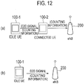
Fig. 12 is a diagram showing an MBMS control method according to the fifth embodiment. - In the fifth embodiment, the MBMS-compliant UE 100-1 further supports D2D communication, which is direct communication between UEs. As shown in
Fig. 12 , the MBMS control method comprises a step of transmitting, by an MBMS-compliant UE 100-1 that receives an MBMS counting request, an MBMS counting response (Counting information) by using a D2D signal, in an RRC idle state. The D2D signal is a D2D discovery-use signal (Discovery signal) that is used for discovering a neighboring UE. Alternatively, the D2D signal is a D2D synchronization signal that is used for establishing synchronization between UEs. - As shown in
Fig. 12 (a) , the MBMS control method according to the fifth embodiment comprises the steps of: receiving, by an RRC connection UE 100-2, an MBMS counting response that is transmitted by using a D2D signal; and transferring, by the RRC connection UE 100-2, to a network (an eNB 200), the received MBMS counting response. In the step of transferring, the RRC connection UE 100-2, transfers the received MBMS counting response, to the network, together with an identifier of the MBMS-compliant UE 100-1. - In this way, in the fifth embodiment, the RRC connection UE 100-2 relays the MBMS counting response (Counting information) to the network. Thus, the MBMS-compliant UE 100-1 can convey the MBMS counting response to the network while maintaining the RRC idle state.
- Alternatively, as shown in
Fig. 12 (b) , the MBMS control method according to the fifth embodiment comprises a step of (directly) receiving, by the network (the eNB 200), the MBMS counting response that is transmitted by using a D2D signal. - In this way, the network may directly receive the D2D signal (the MBMS counting response) rather than the RRC connection UE 100-2 relaying the D2D signal (the MBMS counting response) to the network. Thus, the MBMS-compliant UE 100-1 can convey the MBMS counting response to the network while maintaining the RRC idle state.
- A case in which the D2D signal is a Discovery signal will be illustrated below.
Fig. 13 is a diagram showing a method of transmitting a Discovery signal. As shown inFig. 13 , the Discovery signal is transmitted periodically by using a fixed frequency resource. The MBMS-compliant UE 100-1 that receives an MBMS counting request transmits an MBMS counting response (Counting information) by including in a Discovery signal, in an RRC idle state. - Hereinafter, an operation sequence according to the fifth embodiment will be described.
Fig. 14 is a diagram showing an operation sequence according to the fifth embodiment. In an initial state shown inFig. 14 , the MBMS-compliant UE 100-1 is in an RRC idle state (Idle mode). - As shown in
Fig. 14 , in step S501, theMCE 330 transmits, to theeNB 200, a request for MBMS counting (enhanced Counting Request). Similar to the first embodiment, the request for MBMS counting includes a Counting Request List, a message effective period, and a message ID. - In step S502, the
eNB 200 transmits the MBMS counting request (enhanced Counting Request Message) through an SIB in response to a request from theMCE 330. The MBMS counting request includes the Counting Request List, the message effective period, and the message ID. In the fifth embodiment, the MBMS counting request may include information for specifying a frequency (for example, each time, or once in X no. of times) of including the MBMS counting response (Counting information) in the Discovery signal. - The MBMS-compliant UE 100-1 that receives the MBMS counting request starts a timer for timing the message effective period. Further, the
eNB 200 that has transmitted the MBMS counting request may start a timer for timing the message effective period. - In step S503, the MBMS-compliant UE 100-1 transmits an MBMS counting response (Counting information) by including in a Discovery signal. The RRC connection UE 100-2 and/or the
eNB 200 receive(s) the Discovery signal. A configuration example of the Discovery signal will be described later. - In step S504, the RRC connection UE 100-2 that receives the Discovery signal including the MBMS counting response (Counting information), retains the received MBMS counting response until the expiry of the message effective period, and aggregates the MBMS counting responses.
- In step S505, the
eNB 200 that receives the Discovery signal including the MBMS counting response (Counting information), retains the received MBMS counting response until the expiry of the message effective period, and aggregates the MBMS counting responses. - In step S506, the RRC connection UE 100-2 transmits, to the
eNB 200, the MBMS counting response after aggregation. - In step S507, the
eNB 200 performs the process for resolving overlapping of the MBMS counting response. Details of the process will be described later. - In step S508, the
eNB 200 transmits the MBMS counting report (enhanced Counting Report) to theMCE 330. The MBMS counting report includes a Counting Response List. -
Fig. 15 is a diagram showing a configuration example of the Discovery signal. - As shown in
Fig. 15 (a) , in addition to the information (such as a transmission-source UE identifier, etc.) included in the normal Discovery signal, the Discovery signal includes an MBSFN area Index, a message ID, and a Counting Response List. - Alternatively, as shown in
Fig. 15 (b) , the information about whether or not (0/1) there is an interest in only a specific MBMS service may be used in place of the Counting Response List shown inFig. 15 (a) . In this case, it is necessary to specify the specific MBMS service in the MBMS counting request. - Alternatively, as shown in
Fig. 15 (c) , the information indicating the MBMS service in which there is the most interest/the least interest from among the MBMS services included in the Counting Request List may be used in place of the Counting Response List shown inFig. 15 (a) . - It is noted that cases in which the Discovery signal is used for a purpose other than the D2D communication and the MBMS counting procedure may also be considered, and information indicating that the Discovery signal is used for the purpose of the MBMS counting procedure may be included in the Discovery signal. Purposes other than the D2D communication and the MBMS counting procedure include, for example, an MBMS Interest Indication Procedure for guaranteeing MBMS reception continuity (for example, see Non Patent Literature 1), or an MBMS MDT procedure for collecting measurements of the MBMS reception status.
- Further, the RRC connection UE 100-2 that receives the Discovery signal including the MBMS counting response (Counting information) may transmit a response signal corresponding to the Discovery signal. When the MBMS-
compliant UE 100 cannot receive a response signal within a predetermined time from the time of transmitting the Discovery signal including the MBMS counting response (Counting information), the MBMS-compliant UE 100 may transition to the RRC connected state, and transmit an MBMS counting response (Counting information) to the network. -
Fig. 16 is a diagram for describing an operation of the RRC connection UE 100-2 or theeNB 200 that receives the Discovery signal including the MBMS counting response (Counting information). - As shown in
Fig. 16 , to ensure that there is no overlapping, the RRC connection UE 100-2 or theeNB 200 that receives the Discovery signal including the MBMS counting response (Counting information) is stored with associating the transmission-source UE identifier of the Discovery signal and the Counting information. The message ID and the MBSFN area Index may be further associated. -
Fig. 17 is a diagram for describing a process for resolving an overlapping of an MBMS counting response. - As shown in
Fig. 17 (a) , theeNB 200 checks matching or mismatching of the transmission-source UE identifier with regard to the MBMS counting response (Counting information) from the RRC connection UE 100-2, and the MBMS counting response (Counting information) retained in theeNB 200 itself. - As shown in
Fig. 17 (b) , if the transmission-source UE identifier is matching, then the overlapping MBMS counting response (Counting information) is integrated into one. As a result, the overlapping of the MBMS counting response is resolved. - The aforementioned first embodiment to the fifth embodiment may be performed separately and independently and may also be performed by combining at least two embodiments.
- In each of the above-described embodiments, an MBMS-compliant terminal performs a predetermined operation for transmitting an MBMS counting response on the basis of an MBMS counting request; however, this is not limiting. For example, if a base station can notify that the MBMS is terminated before the termination of a predetermined MBMS, then an MBMS-compliant terminal that is in an idle state may perform a predetermined operation for transmitting the MBMS counting response on the basis of the reception of the MBMS termination notification. In that case, the MBMS-compliant terminal that is in the idle state does not perform the predetermined operation even if receiving the MBMS counting request.
- Furthermore, in each of the above-described embodiments, the LTE system is described as an example of a mobile communication system; however, the present invention may be applied not only to the LTE system but also to a system other than the LTE system.
- It is noted that the entire content of
Japanese Patent Application No. 2014-032295 (filed on February 21, 2014 - As stated above, the MBMS control method, the user terminal, and the base station according to the present embodiment are useful in the field of mobile communication because it is possible to sufficiently understand a demand status for an MBMS service in a network.
Claims (19)
- An Multimedia Broadcast/Multicast Service (MBMS) control method for understanding a demand status for an MBMS service that is provided from a network of a mobile communication system, by multicast or broadcast, in the network, comprising the steps of:transmitting, by a base station included in the network, an MBMS counting request for counting user terminals that either receive or have an interest in receiving the MBMS service, by using a predetermined signal that can be received by a user terminal in an RRC idle state;receiving, by an MBMS-compliant terminal that supports MBMS reception, the MBMS counting request transmitted by using the predetermined signal, in the RRC idle state; andperforming, by the MBMS-compliant terminal, a predetermined operation for transmitting an MBMS counting response, on the basis of the received MBMS counting request.
- The MBMS control method according to claim 1, wherein
the predetermined signal is a broadcast signal or a multicast signal. - The MBMS control method according to claim 2, further comprising a step of
requesting, by an MBMS control apparatus included in the network, to the base station, the transmission of the MBMS counting request, wherein
in the step of transmitting the MBMS counting request, the base station transmits the MBMS counting request in response to the request from the MBMS control apparatus. - The MBMS control method according to claim 2, wherein
the step of performing the predetermined operation comprises a step of holding, by the MBMS-compliant terminal that receives the MBMS counting request, the transmission of the MBMS counting response until the MBMS-compliant terminal transitions to an RRC connected state, and
the MBMS control method further comprises:a step of transmitting, by the MBMS-compliant terminal, the MBMS counting response to the network, after transitioning to the RRC connected state. - The MBMS control method according to claim 4, wherein
the MBMS counting request includes information indicating a message effective period of the MBMS counting request, such that
when the message effective period expires before transition to the RRC connected state, the MBMS-compliant terminal that receives the MBMS counting request cancels the transmission of the MBMS counting response. - The MBMS control method according to claim 4, wherein
the MBMS counting request includes a message identifier of the MBMS counting request, and
in the step of transmitting the MBMS counting response, the MBMS-compliant terminal transmits the MBMS counting response including the message identifier, to the network. - The MBMS control method according to claim 2, wherein
the step of performing the predetermined operation comprises a step of performing, by the MBMS-compliant terminal that receives the MBMS counting request, a random access procedure for the network, upon satisfying a predetermined condition, and
the MBMS control method further comprises:a step of transmitting, by the MBMS-compliant terminal that has transitioned to the RRC connected state through the random access procedure, to the network, the MBMS counting response. - The MBMS control method according to claim 7, wherein
the MBMS counting request includes an MBMS service identifier, and
the predetermined condition is a condition according to which the MBMS-compliant terminal either receives or has an interest in receiving an MBMS service indicated by the MBMS service identifier. - The MBMS control method according to claim 7, wherein
the predetermined condition is a condition according to which a paging signal addressed to the MBMS-compliant terminal is received separately from the MBMS counting request. - The MBMS control method according to claim 1, wherein
the predetermined signal is a paging signal addressed to the MBMS-compliant terminal, and
after transitioning to the RRC connected state, the MBMS-compliant terminal that receives the MBMS counting request transmitted by using the paging signal, transmits the MBMS counting response to the network. - The MBMS control method according to claim 9, further comprising a step of
determining, by the base station that transmits the paging signal, a transmission destination of the paging signal on the basis of at least either one of a status of handover of a user terminal to the base station, and a status of availability of a non-contention-based random access preamble secured by the base station. - The MBMS control method according to claim 1, wherein
the step of performing the predetermined operation comprises a step of performing, by the MBMS-compliant terminal that receives the MBMS counting request, a random access procedure for the network, and
the MBMS control method further comprises:a step of transmitting, by the MBMS-compliant terminal that has transitioned to the RRC connected state through the random access procedure, to the network, an MBMS counting response, andthe MBMS counting request includes control information for controlling a timing of transmitting a random access preamble in the random access procedure. - The MBMS control method according to claim 12, wherein
the control information includes a standard time interval and a maximum time interval of transmitting the random access preamble, and
the step of performing the random access procedure determines a timing of transmitting the random access preamble on the basis of the standard time interval and a random number, within a range in which the maximum time interval is not exceeded. - The MBMS control method according to claim 2, wherein
the MBMS-compliant terminal further supports D2D communication, which is direct communication between terminals, and
the step of performing the predetermined operation comprises a step of transmitting, by the MBMS-compliant terminal that receives the MBMS counting request, the MBMS counting response through a D2D signal, in the RRC idle state. - The MBMS control method according to claim 14, further comprising the steps of:receiving, by an RRC connection terminal which is a user terminal in an RRC connected state, the MBMS counting response that is transmitted by using the D2D signal; andtransferring, by the RRC connection terminal, to the network, the received MBMS counting response.
- The MBMS control method according to claim 15, wherein in the step of
transferring, the RRC connection terminal transfers the received MBMS counting response, to the network, together with an identifier of the MBMS-compliant terminal. - The MBMS control method according to claim 14, further comprising:a step of receiving, by the network, the MBMS counting response that is transmitted by using the D2D signal.
- A user terminal that supports Multimedia Broadcast/Multicast Service (MBMS) reception, comprising:a receiver configured to receive, from a base station included in a network that provides an MBMS service either by multicast or broadcast, an MBMS counting request for counting the user terminals that either receive or have an interest in receiving the MBMS service; anda controller configured to perform a predetermined operation for transmitting an MBMS counting response on the basis of the received MBMS counting request, whereinthe MBMS counting request is transmitted by a predetermined signal that can be received by a user terminal in an RRC idle state, andthe receiver receives the MBMS counting request transmitted by the predetermined signal, when the user terminal itself is in the RRC idle state.
- A base station that supports a Multimedia Broadcast/Multicast Service (MBMS) service, comprising:a transmitter configured to transmit an MBMS counting request for counting the user terminals that either receive or have an interest in receiving the MBMS service, by a predetermined signal that can be received by a user terminal in an RRC idle state, whereinthe MBMS counting request is a request for a user terminal to perform a predetermined operation for transmitting an MBMS counting response.
Applications Claiming Priority (2)
| Application Number | Priority Date | Filing Date | Title |
|---|---|---|---|
| JP2014032295 | 2014-02-21 | ||
| PCT/JP2015/054700 WO2015125901A1 (en) | 2014-02-21 | 2015-02-20 | Mbms control method, user terminal, and base station |
Publications (3)
| Publication Number | Publication Date |
|---|---|
| EP3110181A1 true EP3110181A1 (en) | 2016-12-28 |
| EP3110181A4 EP3110181A4 (en) | 2017-10-25 |
| EP3110181B1 EP3110181B1 (en) | 2019-04-03 |
Family
ID=53878398
Family Applications (1)
| Application Number | Title | Priority Date | Filing Date |
|---|---|---|---|
| EP15751565.1A Active EP3110181B1 (en) | 2014-02-21 | 2015-02-20 | Mbms control method, user terminal, and base station |
Country Status (4)
| Country | Link |
|---|---|
| US (1) | US10194281B2 (en) |
| EP (1) | EP3110181B1 (en) |
| JP (1) | JP6461908B2 (en) |
| WO (1) | WO2015125901A1 (en) |
Cited By (2)
| Publication number | Priority date | Publication date | Assignee | Title |
|---|---|---|---|---|
| EP3376814A4 (en) * | 2015-11-12 | 2018-10-31 | Fujitsu Limited | Terminal device, base station device, wireless communication system, and wireless communication method |
| WO2022077401A1 (en) * | 2020-10-15 | 2022-04-21 | 北京小米移动软件有限公司 | Service participation determination method and apparatus, network element device, user equipment and storage medium |
Families Citing this family (11)
| Publication number | Priority date | Publication date | Assignee | Title |
|---|---|---|---|---|
| CN104955065A (en) * | 2014-03-31 | 2015-09-30 | 北京三星通信技术研究有限公司 | Method for carrying out user statistics, method for suspending data transmission and device thereof |
| WO2016039017A1 (en) * | 2014-09-12 | 2016-03-17 | ソニー株式会社 | Device |
| WO2016167606A1 (en) * | 2015-04-15 | 2016-10-20 | 엘지전자 주식회사 | Method for performing feedback by terminal in wireless communication system and apparatus therefor |
| WO2017164587A1 (en) * | 2016-03-25 | 2017-09-28 | Lg Electronics Inc. | Method for reporting feedback information for v2x communication and apparatus therefor |
| WO2018034473A1 (en) * | 2016-08-14 | 2018-02-22 | Samsung Electronics Co., Ltd. | System and method for multimedia broadcast multicast service (mbms) counting operation |
| WO2018043243A1 (en) * | 2016-08-30 | 2018-03-08 | 京セラ株式会社 | Radio terminal and base station |
| US10536859B2 (en) | 2017-08-15 | 2020-01-14 | Charter Communications Operating, Llc | Methods and apparatus for dynamic control and utilization of quasi-licensed wireless spectrum |
| US10340976B2 (en) | 2017-10-16 | 2019-07-02 | Charter Communications Operating, Llc | Methods and apparatus for coordinated utilization of quasi-licensed wireless spectrum |
| CN111586811B (en) * | 2019-02-18 | 2023-08-15 | 中国移动通信有限公司研究院 | Information processing method and terminal |
| US11317296B2 (en) * | 2019-10-02 | 2022-04-26 | Charter Communications Operating, Llc | Apparatus and methods for interference handling and switching operating frequencies for devices being supported by a wireless access node |
| CN113141581B (en) * | 2020-01-20 | 2022-06-07 | 大唐移动通信设备有限公司 | Method, equipment and medium for reporting and determining interest of multicast broadcast service |
Family Cites Families (7)
| Publication number | Priority date | Publication date | Assignee | Title |
|---|---|---|---|---|
| KR20040064867A (en) * | 2003-01-10 | 2004-07-21 | 삼성전자주식회사 | Method for providing random access effectively in mobile telecommunication system |
| EA014639B1 (en) * | 2006-10-31 | 2010-12-30 | Шарп Кабусики Кайся | Mobile communication system, base station apparatus and mobile station apparatus |
| GB2485237A (en) * | 2010-11-08 | 2012-05-09 | Nec Corp | MBMS provided by unicast or broadcast/multicast in dependence on the number of interested users. |
| US9936472B2 (en) * | 2011-02-08 | 2018-04-03 | Qualcomm Incorporated | Method and apparatus for counting devices related to broadcast data services |
| US9191784B2 (en) * | 2011-10-31 | 2015-11-17 | Kyocera Corporation | Multimedia broadcast multicast service (MBMS) counting procedures |
| US10588101B2 (en) * | 2012-01-06 | 2020-03-10 | Qualcomm Incorporated | Long term evoluton (LTE) user equipment relays having a licensed wireless or wired backhaul link and an unlicensed access link |
| KR101792515B1 (en) * | 2013-04-01 | 2017-11-02 | 엘지전자 주식회사 | Multimedia broadcast/multicast service method and apparatus for device-to-device (d2d) communication in wireless communication system |
-
2015
- 2015-02-20 EP EP15751565.1A patent/EP3110181B1/en active Active
- 2015-02-20 JP JP2016504178A patent/JP6461908B2/en active Active
- 2015-02-20 WO PCT/JP2015/054700 patent/WO2015125901A1/en active Application Filing
- 2015-02-20 US US15/119,198 patent/US10194281B2/en active Active
Cited By (4)
| Publication number | Priority date | Publication date | Assignee | Title |
|---|---|---|---|---|
| EP3376814A4 (en) * | 2015-11-12 | 2018-10-31 | Fujitsu Limited | Terminal device, base station device, wireless communication system, and wireless communication method |
| US10966244B2 (en) | 2015-11-12 | 2021-03-30 | Fujitsu Limited | Terminal device, base station device, wireless communication system, and wireless communication method |
| US11856601B2 (en) | 2015-11-12 | 2023-12-26 | Fujitsu Limited | Terminal device, base station device, wireless communication system, and wireless communication method for allocating random access resources in an unlicensed band |
| WO2022077401A1 (en) * | 2020-10-15 | 2022-04-21 | 北京小米移动软件有限公司 | Service participation determination method and apparatus, network element device, user equipment and storage medium |
Also Published As
| Publication number | Publication date |
|---|---|
| EP3110181A4 (en) | 2017-10-25 |
| EP3110181B1 (en) | 2019-04-03 |
| US20170013422A1 (en) | 2017-01-12 |
| JP6461908B2 (en) | 2019-01-30 |
| US10194281B2 (en) | 2019-01-29 |
| JPWO2015125901A1 (en) | 2017-03-30 |
| WO2015125901A1 (en) | 2015-08-27 |
Similar Documents
| Publication | Publication Date | Title |
|---|---|---|
| EP3110181B1 (en) | Mbms control method, user terminal, and base station | |
| US10911999B2 (en) | Mobile communication system, user terminal, base station, processor, and communication control method | |
| US10477380B2 (en) | Base station and radio terminal | |
| US20160278045A1 (en) | Communication control method | |
| US10142892B2 (en) | Base station and user terminal performing connection reestablishment processing | |
| EP3065485A1 (en) | Mobile communication system and user terminals | |
| US10098162B2 (en) | Mobile communication system, user terminal, base station, processor, and communication control method | |
| US9706464B2 (en) | Communication control method, user terminal, and processor | |
| EP3668268A1 (en) | Mobile communication system, user terminal, and base station | |
| EP3249982A1 (en) | User terminal and base station | |
| EP2903393A1 (en) | Mobile communication system, base station, and user terminal | |
| EP3065488A1 (en) | Communication control method, base station, and user terminal | |
| EP3101977A1 (en) | Mobile communication system and user terminal | |
| US10382570B2 (en) | Base station and user terminal | |
| US20160081123A1 (en) | User terminal, base station, and processor | |
| US10004101B2 (en) | Mobile communication system, user terminal, and processor | |
| US20160360383A1 (en) | Mbms control method, user terminal, and base station | |
| US9456463B2 (en) | Mobile communication system, user terminal, and communication control method | |
| US9900763B2 (en) | User terminal for determining whether to transmit synchronization signal in response to a received power | |
| US20160057792A1 (en) | Mobile communication system, base station, and user terminal | |
| WO2014157397A1 (en) | Communication control method, user terminal, and base station |
Legal Events
| Date | Code | Title | Description |
|---|---|---|---|
| PUAI | Public reference made under article 153(3) epc to a published international application that has entered the european phase |
Free format text: ORIGINAL CODE: 0009012 |
|
| STAA | Information on the status of an ep patent application or granted ep patent |
Free format text: STATUS: REQUEST FOR EXAMINATION WAS MADE |
|
| 17P | Request for examination filed |
Effective date: 20160812 |
|
| AK | Designated contracting states |
Kind code of ref document: A1 Designated state(s): AL AT BE BG CH CY CZ DE DK EE ES FI FR GB GR HR HU IE IS IT LI LT LU LV MC MK MT NL NO PL PT RO RS SE SI SK SM TR |
|
| AX | Request for extension of the european patent |
Extension state: BA ME |
|
| DAX | Request for extension of the european patent (deleted) | ||
| RIC1 | Information provided on ipc code assigned before grant |
Ipc: H04L 12/18 20060101ALI20170914BHEP Ipc: H04W 74/08 20090101ALI20170914BHEP Ipc: H04W 4/06 20090101AFI20170914BHEP |
|
| A4 | Supplementary search report drawn up and despatched |
Effective date: 20170925 |
|
| GRAP | Despatch of communication of intention to grant a patent |
Free format text: ORIGINAL CODE: EPIDOSNIGR1 |
|
| STAA | Information on the status of an ep patent application or granted ep patent |
Free format text: STATUS: GRANT OF PATENT IS INTENDED |
|
| INTG | Intention to grant announced |
Effective date: 20181029 |
|
| GRAS | Grant fee paid |
Free format text: ORIGINAL CODE: EPIDOSNIGR3 |
|
| GRAA | (expected) grant |
Free format text: ORIGINAL CODE: 0009210 |
|
| STAA | Information on the status of an ep patent application or granted ep patent |
Free format text: STATUS: THE PATENT HAS BEEN GRANTED |
|
| AK | Designated contracting states |
Kind code of ref document: B1 Designated state(s): AL AT BE BG CH CY CZ DE DK EE ES FI FR GB GR HR HU IE IS IT LI LT LU LV MC MK MT NL NO PL PT RO RS SE SI SK SM TR |
|
| REG | Reference to a national code |
Ref country code: GB Ref legal event code: FG4D |
|
| REG | Reference to a national code |
Ref country code: CH Ref legal event code: EP Ref country code: AT Ref legal event code: REF Ref document number: 1117271 Country of ref document: AT Kind code of ref document: T Effective date: 20190415 |
|
| REG | Reference to a national code |
Ref country code: DE Ref legal event code: R096 Ref document number: 602015027613 Country of ref document: DE |
|
| REG | Reference to a national code |
Ref country code: IE Ref legal event code: FG4D |
|
| REG | Reference to a national code |
Ref country code: NL Ref legal event code: MP Effective date: 20190403 |
|
| REG | Reference to a national code |
Ref country code: LT Ref legal event code: MG4D |
|
| REG | Reference to a national code |
Ref country code: AT Ref legal event code: MK05 Ref document number: 1117271 Country of ref document: AT Kind code of ref document: T Effective date: 20190403 |
|
| PG25 | Lapsed in a contracting state [announced via postgrant information from national office to epo] |
Ref country code: NL Free format text: LAPSE BECAUSE OF FAILURE TO SUBMIT A TRANSLATION OF THE DESCRIPTION OR TO PAY THE FEE WITHIN THE PRESCRIBED TIME-LIMIT Effective date: 20190403 |
|
| PG25 | Lapsed in a contracting state [announced via postgrant information from national office to epo] |
Ref country code: NO Free format text: LAPSE BECAUSE OF FAILURE TO SUBMIT A TRANSLATION OF THE DESCRIPTION OR TO PAY THE FEE WITHIN THE PRESCRIBED TIME-LIMIT Effective date: 20190703 Ref country code: FI Free format text: LAPSE BECAUSE OF FAILURE TO SUBMIT A TRANSLATION OF THE DESCRIPTION OR TO PAY THE FEE WITHIN THE PRESCRIBED TIME-LIMIT Effective date: 20190403 Ref country code: CZ Free format text: LAPSE BECAUSE OF FAILURE TO SUBMIT A TRANSLATION OF THE DESCRIPTION OR TO PAY THE FEE WITHIN THE PRESCRIBED TIME-LIMIT Effective date: 20190403 Ref country code: SE Free format text: LAPSE BECAUSE OF FAILURE TO SUBMIT A TRANSLATION OF THE DESCRIPTION OR TO PAY THE FEE WITHIN THE PRESCRIBED TIME-LIMIT Effective date: 20190403 Ref country code: ES Free format text: LAPSE BECAUSE OF FAILURE TO SUBMIT A TRANSLATION OF THE DESCRIPTION OR TO PAY THE FEE WITHIN THE PRESCRIBED TIME-LIMIT Effective date: 20190403 Ref country code: AL Free format text: LAPSE BECAUSE OF FAILURE TO SUBMIT A TRANSLATION OF THE DESCRIPTION OR TO PAY THE FEE WITHIN THE PRESCRIBED TIME-LIMIT Effective date: 20190403 Ref country code: PT Free format text: LAPSE BECAUSE OF FAILURE TO SUBMIT A TRANSLATION OF THE DESCRIPTION OR TO PAY THE FEE WITHIN THE PRESCRIBED TIME-LIMIT Effective date: 20190803 Ref country code: LT Free format text: LAPSE BECAUSE OF FAILURE TO SUBMIT A TRANSLATION OF THE DESCRIPTION OR TO PAY THE FEE WITHIN THE PRESCRIBED TIME-LIMIT Effective date: 20190403 Ref country code: HR Free format text: LAPSE BECAUSE OF FAILURE TO SUBMIT A TRANSLATION OF THE DESCRIPTION OR TO PAY THE FEE WITHIN THE PRESCRIBED TIME-LIMIT Effective date: 20190403 |
|
| PG25 | Lapsed in a contracting state [announced via postgrant information from national office to epo] |
Ref country code: GR Free format text: LAPSE BECAUSE OF FAILURE TO SUBMIT A TRANSLATION OF THE DESCRIPTION OR TO PAY THE FEE WITHIN THE PRESCRIBED TIME-LIMIT Effective date: 20190704 Ref country code: PL Free format text: LAPSE BECAUSE OF FAILURE TO SUBMIT A TRANSLATION OF THE DESCRIPTION OR TO PAY THE FEE WITHIN THE PRESCRIBED TIME-LIMIT Effective date: 20190403 Ref country code: LV Free format text: LAPSE BECAUSE OF FAILURE TO SUBMIT A TRANSLATION OF THE DESCRIPTION OR TO PAY THE FEE WITHIN THE PRESCRIBED TIME-LIMIT Effective date: 20190403 Ref country code: BG Free format text: LAPSE BECAUSE OF FAILURE TO SUBMIT A TRANSLATION OF THE DESCRIPTION OR TO PAY THE FEE WITHIN THE PRESCRIBED TIME-LIMIT Effective date: 20190703 Ref country code: RS Free format text: LAPSE BECAUSE OF FAILURE TO SUBMIT A TRANSLATION OF THE DESCRIPTION OR TO PAY THE FEE WITHIN THE PRESCRIBED TIME-LIMIT Effective date: 20190403 |
|
| PG25 | Lapsed in a contracting state [announced via postgrant information from national office to epo] |
Ref country code: AT Free format text: LAPSE BECAUSE OF FAILURE TO SUBMIT A TRANSLATION OF THE DESCRIPTION OR TO PAY THE FEE WITHIN THE PRESCRIBED TIME-LIMIT Effective date: 20190403 Ref country code: IS Free format text: LAPSE BECAUSE OF FAILURE TO SUBMIT A TRANSLATION OF THE DESCRIPTION OR TO PAY THE FEE WITHIN THE PRESCRIBED TIME-LIMIT Effective date: 20190803 |
|
| REG | Reference to a national code |
Ref country code: DE Ref legal event code: R097 Ref document number: 602015027613 Country of ref document: DE |
|
| PG25 | Lapsed in a contracting state [announced via postgrant information from national office to epo] |
Ref country code: RO Free format text: LAPSE BECAUSE OF FAILURE TO SUBMIT A TRANSLATION OF THE DESCRIPTION OR TO PAY THE FEE WITHIN THE PRESCRIBED TIME-LIMIT Effective date: 20190403 Ref country code: EE Free format text: LAPSE BECAUSE OF FAILURE TO SUBMIT A TRANSLATION OF THE DESCRIPTION OR TO PAY THE FEE WITHIN THE PRESCRIBED TIME-LIMIT Effective date: 20190403 Ref country code: DK Free format text: LAPSE BECAUSE OF FAILURE TO SUBMIT A TRANSLATION OF THE DESCRIPTION OR TO PAY THE FEE WITHIN THE PRESCRIBED TIME-LIMIT Effective date: 20190403 Ref country code: SK Free format text: LAPSE BECAUSE OF FAILURE TO SUBMIT A TRANSLATION OF THE DESCRIPTION OR TO PAY THE FEE WITHIN THE PRESCRIBED TIME-LIMIT Effective date: 20190403 |
|
| PLBE | No opposition filed within time limit |
Free format text: ORIGINAL CODE: 0009261 |
|
| STAA | Information on the status of an ep patent application or granted ep patent |
Free format text: STATUS: NO OPPOSITION FILED WITHIN TIME LIMIT |
|
| PG25 | Lapsed in a contracting state [announced via postgrant information from national office to epo] |
Ref country code: IT Free format text: LAPSE BECAUSE OF FAILURE TO SUBMIT A TRANSLATION OF THE DESCRIPTION OR TO PAY THE FEE WITHIN THE PRESCRIBED TIME-LIMIT Effective date: 20190403 Ref country code: SM Free format text: LAPSE BECAUSE OF FAILURE TO SUBMIT A TRANSLATION OF THE DESCRIPTION OR TO PAY THE FEE WITHIN THE PRESCRIBED TIME-LIMIT Effective date: 20190403 |
|
| 26N | No opposition filed |
Effective date: 20200106 |
|
| PG25 | Lapsed in a contracting state [announced via postgrant information from national office to epo] |
Ref country code: TR Free format text: LAPSE BECAUSE OF FAILURE TO SUBMIT A TRANSLATION OF THE DESCRIPTION OR TO PAY THE FEE WITHIN THE PRESCRIBED TIME-LIMIT Effective date: 20190403 |
|
| PGFP | Annual fee paid to national office [announced via postgrant information from national office to epo] |
Ref country code: DE Payment date: 20200204 Year of fee payment: 6 Ref country code: GB Payment date: 20200212 Year of fee payment: 6 |
|
| PG25 | Lapsed in a contracting state [announced via postgrant information from national office to epo] |
Ref country code: SI Free format text: LAPSE BECAUSE OF FAILURE TO SUBMIT A TRANSLATION OF THE DESCRIPTION OR TO PAY THE FEE WITHIN THE PRESCRIBED TIME-LIMIT Effective date: 20190403 |
|
| PGFP | Annual fee paid to national office [announced via postgrant information from national office to epo] |
Ref country code: FR Payment date: 20200113 Year of fee payment: 6 |
|
| REG | Reference to a national code |
Ref country code: CH Ref legal event code: PL |
|
| REG | Reference to a national code |
Ref country code: BE Ref legal event code: MM Effective date: 20200229 |
|
| PG25 | Lapsed in a contracting state [announced via postgrant information from national office to epo] |
Ref country code: MC Free format text: LAPSE BECAUSE OF FAILURE TO SUBMIT A TRANSLATION OF THE DESCRIPTION OR TO PAY THE FEE WITHIN THE PRESCRIBED TIME-LIMIT Effective date: 20190403 Ref country code: LU Free format text: LAPSE BECAUSE OF NON-PAYMENT OF DUE FEES Effective date: 20200220 |
|
| PG25 | Lapsed in a contracting state [announced via postgrant information from national office to epo] |
Ref country code: LI Free format text: LAPSE BECAUSE OF NON-PAYMENT OF DUE FEES Effective date: 20200229 Ref country code: CH Free format text: LAPSE BECAUSE OF NON-PAYMENT OF DUE FEES Effective date: 20200229 |
|
| PG25 | Lapsed in a contracting state [announced via postgrant information from national office to epo] |
Ref country code: IE Free format text: LAPSE BECAUSE OF NON-PAYMENT OF DUE FEES Effective date: 20200220 |
|
| PG25 | Lapsed in a contracting state [announced via postgrant information from national office to epo] |
Ref country code: BE Free format text: LAPSE BECAUSE OF NON-PAYMENT OF DUE FEES Effective date: 20200229 |
|
| REG | Reference to a national code |
Ref country code: DE Ref legal event code: R119 Ref document number: 602015027613 Country of ref document: DE |
|
| GBPC | Gb: european patent ceased through non-payment of renewal fee |
Effective date: 20210220 |
|
| PG25 | Lapsed in a contracting state [announced via postgrant information from national office to epo] |
Ref country code: DE Free format text: LAPSE BECAUSE OF NON-PAYMENT OF DUE FEES Effective date: 20210901 Ref country code: GB Free format text: LAPSE BECAUSE OF NON-PAYMENT OF DUE FEES Effective date: 20210220 Ref country code: FR Free format text: LAPSE BECAUSE OF NON-PAYMENT OF DUE FEES Effective date: 20210228 |
|
| PG25 | Lapsed in a contracting state [announced via postgrant information from national office to epo] |
Ref country code: MT Free format text: LAPSE BECAUSE OF FAILURE TO SUBMIT A TRANSLATION OF THE DESCRIPTION OR TO PAY THE FEE WITHIN THE PRESCRIBED TIME-LIMIT Effective date: 20190403 Ref country code: CY Free format text: LAPSE BECAUSE OF FAILURE TO SUBMIT A TRANSLATION OF THE DESCRIPTION OR TO PAY THE FEE WITHIN THE PRESCRIBED TIME-LIMIT Effective date: 20190403 |
|
| PG25 | Lapsed in a contracting state [announced via postgrant information from national office to epo] |
Ref country code: MK Free format text: LAPSE BECAUSE OF FAILURE TO SUBMIT A TRANSLATION OF THE DESCRIPTION OR TO PAY THE FEE WITHIN THE PRESCRIBED TIME-LIMIT Effective date: 20190403 |