EP3110123A1 - Detection of proof-correction information in manuscript images - Google Patents
Detection of proof-correction information in manuscript images Download PDFInfo
- Publication number
- EP3110123A1 EP3110123A1 EP16175710.9A EP16175710A EP3110123A1 EP 3110123 A1 EP3110123 A1 EP 3110123A1 EP 16175710 A EP16175710 A EP 16175710A EP 3110123 A1 EP3110123 A1 EP 3110123A1
- Authority
- EP
- European Patent Office
- Prior art keywords
- image data
- proof
- page
- information
- correction
- Prior art date
- Legal status (The legal status is an assumption and is not a legal conclusion. Google has not performed a legal analysis and makes no representation as to the accuracy of the status listed.)
- Ceased
Links
Images


Classifications
-
- H—ELECTRICITY
- H04—ELECTRIC COMMUNICATION TECHNIQUE
- H04N—PICTORIAL COMMUNICATION, e.g. TELEVISION
- H04N1/00—Scanning, transmission or reproduction of documents or the like, e.g. facsimile transmission; Details thereof
- H04N1/00127—Connection or combination of a still picture apparatus with another apparatus, e.g. for storage, processing or transmission of still picture signals or of information associated with a still picture
- H04N1/00204—Connection or combination of a still picture apparatus with another apparatus, e.g. for storage, processing or transmission of still picture signals or of information associated with a still picture with a digital computer or a digital computer system, e.g. an internet server
- H04N1/00244—Connection or combination of a still picture apparatus with another apparatus, e.g. for storage, processing or transmission of still picture signals or of information associated with a still picture with a digital computer or a digital computer system, e.g. an internet server with a server, e.g. an internet server
-
- G—PHYSICS
- G06—COMPUTING OR CALCULATING; COUNTING
- G06F—ELECTRIC DIGITAL DATA PROCESSING
- G06F40/00—Handling natural language data
- G06F40/10—Text processing
- G06F40/166—Editing, e.g. inserting or deleting
- G06F40/169—Annotation, e.g. comment data or footnotes
-
- G—PHYSICS
- G06—COMPUTING OR CALCULATING; COUNTING
- G06F—ELECTRIC DIGITAL DATA PROCESSING
- G06F40/00—Handling natural language data
- G06F40/10—Text processing
- G06F40/194—Calculation of difference between files
-
- G—PHYSICS
- G06—COMPUTING OR CALCULATING; COUNTING
- G06V—IMAGE OR VIDEO RECOGNITION OR UNDERSTANDING
- G06V30/00—Character recognition; Recognising digital ink; Document-oriented image-based pattern recognition
- G06V30/40—Document-oriented image-based pattern recognition
-
- H—ELECTRICITY
- H04—ELECTRIC COMMUNICATION TECHNIQUE
- H04N—PICTORIAL COMMUNICATION, e.g. TELEVISION
- H04N1/00—Scanning, transmission or reproduction of documents or the like, e.g. facsimile transmission; Details thereof
- H04N1/0035—User-machine interface; Control console
- H04N1/00352—Input means
- H04N1/00355—Mark-sheet input
- H04N1/00358—Type of the scanned marks
- H04N1/00366—Marks in boxes or the like, e.g. crosses or blacking out
-
- H—ELECTRICITY
- H04—ELECTRIC COMMUNICATION TECHNIQUE
- H04N—PICTORIAL COMMUNICATION, e.g. TELEVISION
- H04N1/00—Scanning, transmission or reproduction of documents or the like, e.g. facsimile transmission; Details thereof
- H04N1/0035—User-machine interface; Control console
- H04N1/00352—Input means
- H04N1/00355—Mark-sheet input
- H04N1/00368—Location of the scanned marks
- H04N1/00374—Location of the scanned marks on the same page as at least a part of the image
-
- H—ELECTRICITY
- H04—ELECTRIC COMMUNICATION TECHNIQUE
- H04N—PICTORIAL COMMUNICATION, e.g. TELEVISION
- H04N1/00—Scanning, transmission or reproduction of documents or the like, e.g. facsimile transmission; Details thereof
- H04N1/32—Circuits or arrangements for control or supervision between transmitter and receiver or between image input and image output device, e.g. between a still-image camera and its memory or between a still-image camera and a printer device
- H04N1/32101—Display, printing, storage or transmission of additional information, e.g. ID code, date and time or title
- H04N1/32128—Display, printing, storage or transmission of additional information, e.g. ID code, date and time or title attached to the image data, e.g. file header, transmitted message header, information on the same page or in the same computer file as the image
- H04N1/32133—Display, printing, storage or transmission of additional information, e.g. ID code, date and time or title attached to the image data, e.g. file header, transmitted message header, information on the same page or in the same computer file as the image on the same paper sheet, e.g. a facsimile page header
-
- H—ELECTRICITY
- H04—ELECTRIC COMMUNICATION TECHNIQUE
- H04N—PICTORIAL COMMUNICATION, e.g. TELEVISION
- H04N1/00—Scanning, transmission or reproduction of documents or the like, e.g. facsimile transmission; Details thereof
- H04N1/387—Composing, repositioning or otherwise geometrically modifying originals
-
- H—ELECTRICITY
- H04—ELECTRIC COMMUNICATION TECHNIQUE
- H04N—PICTORIAL COMMUNICATION, e.g. TELEVISION
- H04N2201/00—Indexing scheme relating to scanning, transmission or reproduction of documents or the like, and to details thereof
- H04N2201/0008—Connection or combination of a still picture apparatus with another apparatus
- H04N2201/0034—Details of the connection, e.g. connector, interface
- H04N2201/0037—Topological details of the connection
- H04N2201/0039—Connection via a network
-
- H—ELECTRICITY
- H04—ELECTRIC COMMUNICATION TECHNIQUE
- H04N—PICTORIAL COMMUNICATION, e.g. TELEVISION
- H04N2201/00—Indexing scheme relating to scanning, transmission or reproduction of documents or the like, and to details thereof
- H04N2201/0077—Types of the still picture apparatus
- H04N2201/0094—Multifunctional device, i.e. a device capable of all of reading, reproducing, copying, facsimile transception, file transception
-
- H—ELECTRICITY
- H04—ELECTRIC COMMUNICATION TECHNIQUE
- H04N—PICTORIAL COMMUNICATION, e.g. TELEVISION
- H04N2201/00—Indexing scheme relating to scanning, transmission or reproduction of documents or the like, and to details thereof
- H04N2201/32—Circuits or arrangements for control or supervision between transmitter and receiver or between image input and image output device, e.g. between a still-image camera and its memory or between a still-image camera and a printer device
- H04N2201/3201—Display, printing, storage or transmission of additional information, e.g. ID code, date and time or title
- H04N2201/3225—Display, printing, storage or transmission of additional information, e.g. ID code, date and time or title of data relating to an image, a page or a document
- H04N2201/3242—Display, printing, storage or transmission of additional information, e.g. ID code, date and time or title of data relating to an image, a page or a document of processing required or performed, e.g. for reproduction or before recording
-
- H—ELECTRICITY
- H04—ELECTRIC COMMUNICATION TECHNIQUE
- H04N—PICTORIAL COMMUNICATION, e.g. TELEVISION
- H04N2201/00—Indexing scheme relating to scanning, transmission or reproduction of documents or the like, and to details thereof
- H04N2201/32—Circuits or arrangements for control or supervision between transmitter and receiver or between image input and image output device, e.g. between a still-image camera and its memory or between a still-image camera and a printer device
- H04N2201/3201—Display, printing, storage or transmission of additional information, e.g. ID code, date and time or title
- H04N2201/3225—Display, printing, storage or transmission of additional information, e.g. ID code, date and time or title of data relating to an image, a page or a document
- H04N2201/3245—Display, printing, storage or transmission of additional information, e.g. ID code, date and time or title of data relating to an image, a page or a document of image modifying data, e.g. handwritten addenda, highlights or augmented reality information
-
- H—ELECTRICITY
- H04—ELECTRIC COMMUNICATION TECHNIQUE
- H04N—PICTORIAL COMMUNICATION, e.g. TELEVISION
- H04N2201/00—Indexing scheme relating to scanning, transmission or reproduction of documents or the like, and to details thereof
- H04N2201/32—Circuits or arrangements for control or supervision between transmitter and receiver or between image input and image output device, e.g. between a still-image camera and its memory or between a still-image camera and a printer device
- H04N2201/3201—Display, printing, storage or transmission of additional information, e.g. ID code, date and time or title
- H04N2201/3225—Display, printing, storage or transmission of additional information, e.g. ID code, date and time or title of data relating to an image, a page or a document
- H04N2201/3249—Display, printing, storage or transmission of additional information, e.g. ID code, date and time or title of data relating to an image, a page or a document data relating to a linked page or object, e.g. hyperlink
-
- H—ELECTRICITY
- H04—ELECTRIC COMMUNICATION TECHNIQUE
- H04N—PICTORIAL COMMUNICATION, e.g. TELEVISION
- H04N2201/00—Indexing scheme relating to scanning, transmission or reproduction of documents or the like, and to details thereof
- H04N2201/32—Circuits or arrangements for control or supervision between transmitter and receiver or between image input and image output device, e.g. between a still-image camera and its memory or between a still-image camera and a printer device
- H04N2201/3201—Display, printing, storage or transmission of additional information, e.g. ID code, date and time or title
- H04N2201/3271—Printing or stamping
Definitions
- the present invention relates generally to delivery server apparatuses, delivery methods, and delivery systems.
- Patent Document 1 Japanese Laid-open Patent Publication No. 2012-029127 .
- proofreading Process of detecting and correcting errors in a manuscript (hereinafter, sometimes referred to as "proofreading” or “proof correction”) in the publishing industry is performed through the following procedure, for example.
- a publisher prints a digitized not-proofread manuscript and sends the thus-printed not-proofread manuscript (hereinafter, "proof") to an outsource service company providing a service of performing a proofreading process.
- the outsource service company makes handwritten proof correction on the proof and sends the proofread manuscript (i.e., the proof, to which handwritten proof-correction information is added) to the publisher.
- the publisher digitizes the proof, to which the proof-correction information is added, into an electronic form and stores it in a server or the like. Thereafter, the publisher corrects errors on the digitized not-proofread manuscript with reference to the digitized proof, to which the proof-correction information is added, thereby generating a proof-corrected manuscript.
- a delivery server apparatus comprising: a detection portion configured to perform, for each page of image data representing one or more manuscript images, detection of a proof-correction indication image, the proof-correction indication image indicating that the page has proof-correction information; and a generation portion configured to generate output information where link information, the link information being for use in displaying a page where the proof-correction indication image is detected, is added to the image data.
- Exemplary embodiments of the present invention also provide a delivery method comprising: performing, for each page of image data representing one or more manuscript images, detection of a proof-correction indication image, the proof-correction indication image indicating that the page has proof-correction information; and generating output information where link information, the link information being for use in displaying a page where the proof-correction indication image is detected, is added to the image data.
- Exemplary embodiments of the present invention also provide a delivery server apparatus comprising: a detection portion configured to detect a difference between first image data, the first image data being data representing one or more manuscript images, and second image data, the second image data being data representing the manuscript images and containing proof-correction information; and a generation portion configured to generate output information where link information, the link information being for use in displaying a page where the difference is detected, is added to the second image data.
- Exemplary embodiments of the present invention also provide a delivery method comprising: detecting a difference between first image data, the first image data being data representing one or more manuscript images, and second image data, the second image data being data representing the manuscript images and containing proof-correction information; and generating output information where link information, the link information being for use in displaying a page where the difference is detected, is added to the second image data.
- Exemplary embodiments of the present invention also provide A delivery system including an image forming apparatus and a delivery server apparatus, the delivery system comprising: a reading control portion configured to control scanning of a manuscript containing handwritten proof correction; a detection portion configured to perform, for each page of image data representing one or more manuscript images obtained by scanning the manuscript, detection of a proof-correction indication image, the proof-correction indication image indicating that the page has proof-correction information; a generation portion configured to generate output information where link information, the link information being for use in displaying a page where the proof-correction indication image is detected, is added to the image data; and a delivery control portion configured to perform control of delivering the generated output information to an information processing apparatus.
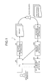
- FIG. 1 is a diagram illustrating an example system configuration of the delivery system according to the first embodiment.
- a delivery system 1 includes a PC (Personal Computer) 80, a printer 90, a scanner 100, a delivery server apparatus 200, and a management server apparatus 300.
- Each of the printer 90 and the scanner 100 of the delivery system 1 may be an image forming apparatus, such as an MFP (Multi-Function Peripheral), capable of providing a copier function, a scanner function, a facsimile function, and a printer function.
- the printer 90 and the scanner 100 may be embodied in a single apparatus (MFP).
- the scanner 100 may be referred to as the image forming apparatus 100 for convenience of description.
- the delivery system 1 according to the first embodiment can be used in a proofreading process of the publishing industry.
- the PC 80 is operated by a manuscript manager, who is a user on publisher's side.
- the manuscript manager operates the PC 80, thereby causing the printer 90 to print image data, which is data representing one or more manuscript images.
- the image data may be stored in the PC 80 or, alternatively, may be stored in the management server apparatus 300 managing various electronic files.
- the PC 80 acquires the image data from the management server apparatus 300 responsive to an operation performed by the manuscript manager.
- the not-proofread manuscript (paper media) (hereinafter, "proof") printed out by the printer 90 contains a checkbox(es) that allows the delivery server apparatus 200 to detect a page(s) where proof correction is made.
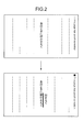
- FIG. 2 is a diagram illustrating an example layout of a manuscript according to the first embodiment.
- each page of the proof printed out by the printer 90 contains a checkbox to be marked by a proofreader when the proofreader makes proof correction.
- the element to be used is not limited to such a checkbox; any mark, symbol, numeric, character, or the like, or a combination of them may alternatively be used so long as it can indicate that proof correction is made on the page.
- the proof with the checkbox may be produced by causing the printer 90 to perform printing using paper, on which the checkbox is preprinted, and a dedicated tray.
- the proof with the checkbox may be produced by generating image data containing the checkbox and causing the printer 90 to print out the generated image data.
- the manuscript manager sends the proof (paper media) printed out by the printer 90 to an outsource service company providing a service of performing a proofreading process.
- a proofreader who is a user on the outsource service company's side, receives the proof and makes handwritten proof correction on the proof. For instance, as illustrated in the lower panel of FIG. 2 , the proofreader marks a portion where a possible error is detected with a line or the like, handwrites a correction candidate or the like, and marks the checkbox to indicate that proof correction is made on this page.
- the proofreader sends the proofread manuscript (paper media) to the publisher.
- the manuscript manager receives the proofread manuscript (paper media) and performs scanning of the proofread manuscript using the scanner 100.
- the scanner 100 scans the proofread manuscript and transmits image data containing a proof-correction indication image(s) (i.e., the marked checkbox(es)), which indicates that the page where the proof-correction indication image resides has proof-correction information, to the delivery server apparatus 200.
- the delivery server apparatus 200 Upon receiving the image data from the scanner 100, the delivery server apparatus 200 performs, for each page of the image data, detection of the proof-correction indication image (the marked checkbox).
- the delivery server apparatus 200 generates output information (e.g., an electronic file) where link information for displaying the page(s) where the proof-correction indication image (the marked checkbox) is detected is added to the image data.
- output information e.g., an electronic file
- the checkbox and a caption, such as "This page has proof correction" may be deleted.
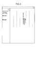
- FIG. 3 is a diagram illustrating example information of the electronic file generated by the delivery server apparatus 200 according to the first embodiment.
- link information e.g., "Page 3" and "Page 7" for displaying the page(s) containing the proof-correction information is added in the electronic file generated by the delivery server apparatus 200 so that, when the link information is selected, the page containing the proof-correction information is displayed.
- FIG. 3 illustrates an example of the electronic file, from which the checkbox and the like are deleted.
- the delivery server apparatus 200 transmits (delivers) the electronic file, in which the link information is added, to the management server apparatus 300.
- the delivery server apparatus 200 may transmit the electronic file, in which the link information is added, to the PC 80.
- the management server apparatus 300 manages the electronic file delivered by the delivery server apparatus 200.
- the PC 80 or the like acquires the electronic file managed by the management server apparatus 300 as necessary.
- the manuscript corrects errors in the digitized proof using the electronic file, in which the link information is added, by operating the PC 80 or the like.
- the delivery system 1 performs, for each page of image data obtained by scanning a manuscript where handwritten proof correction is made, detection of a proof-correction indication image, which indicates that the page contains proof-correction information, and generates an electronic file where link information for displaying the page(s) where the proof-correction indication image is detected is added to the image data.
- the delivery system 1 allows a manuscript manager to correct errors with reference to the electronic file, in which the link information is added, thereby reducing oversights in a proofreading process.
- FIG. 4 is a block diagram illustrating an example hardware structure of the image forming apparatus 100 according to the first embodiment.
- the image forming apparatus 100 includes a controller 10 and an engine section 60 that are connected via a PCI (Peripheral Component Interconnect) bus.
- the controller 10 is a controller that controls the entire image forming apparatus 100, drawing, communication, and various inputs.
- the engine section 60 is a printer engine or the like connectable to the PCI bus. Examples of the engine section 60 include a black-and-white plotter, a one-drum color plotter, a four-drum color plotter, a scanner unit, and a facsimile unit.
- the engine section 60 includes, in addition to what is referred to as an engine portion such as a plotter, a portion for image processing, such as error diffusion and gamma conversion.
- the controller 10 includes a CPU (Central Processing Unit) 11, a north bridge (NB) 13, a system memory (MEM-P) 12, a south bridge (SB) 14, a local memory (MEM-C) 17, an ASIC (Application-Specific Integrated Circuit) 16, and a Hard Disk Drive (HDD) 18, where the north bridge 13 and the ASIC 16 are connected to each other via an AGP (Accelerated Graphics Port) bus 15.
- the MEM-P 12 includes a ROM (Read Only Memory) 12a and a RAM (Random Access Memory) 12b.
- the CPU 11 performs overall control of the image forming apparatus 100 and includes a chip set including the north bridge 13, the MEM-P 12, and the south bridge 14.
- the CPU 11 is connected to other devices via the chip set.
- the north bridge 13 is a bridge for connecting the CPU 11 to the MEM-P 12, the south bridge 14, and the AGP bus 15.
- the north bridge 13 includes a PCI master, an AGP target, and a memory controller that controls reading and writing from and to the MEM-P 12.
- the MEM-P 12 is a system memory for use as a memory where program instructions (hereinafter, "program") and data are to be stored, as a memory where program and data are to be loaded, and as a printer buffer memory and includes the ROM 12a and the RAM 12b.
- the ROM 12a is a read only memory for use as the memory where program and data are to be stored.
- the RAM 12b is a writable and readable memory for use as the memory where program and data are to be loaded and as the printer buffer memory.
- the south bridge 14 is a bridge for connecting between the north bridge 13, and PCI devices and peripheral devices. The south bridge 14 is connected to the north bridge 13 via the PCI bus. A network interface and the like are also connected to this PCI bus.
- the ASIC 16 is an IC (Integrated Circuit) for image processing and includes a hardware component for the image processing.
- the ASIC 16 functions as a bridge that connects between each of the AGP bus 15, the PCI bus, the HDD 18, and the MEM-C 17.
- the ASIC 16 includes a PCI target and an AGP master, an arbiter (ARB), which is a core of the ASIC 16, a memory controller that controls the MEM-C 17, a plurality of DMACs (Direct Memory Access Controllers) that perform image rotation and the like by a hardware logic and the like, and a PCI unit that transfers data to and from the engine section 60 via the PCI bus.
- ARB arbiter
- DMACs Direct Memory Access Controllers
- An FCU (Facsimile Control Unit) 30, a USB (Universal Serial Bus) 40, and an IEEE 1394 (the Institute of Electrical and Electronics Engineers 1394) interface 50 are connected to the ASIC 16 via the PCI bus.
- An operating-and-display unit 20 is directly connected to the ASIC 16.
- the MEM-C 17 is a local memory for use as an image buffer for copying and a code buffer.
- the HDD (Hard Disk Drive) 18 is a storage for accumulating image data, programs, font data, and forms.
- the AGP bus 15 is a bus interface for a graphics accelerator card introduced for speedup of graphics processing and allows direct access to the MEM-P 12 with a high throughput, thereby increasing processing speed of the graphics accelerator card.
- FIG. 5 is a block diagram illustrating an example hardware structure of the delivery server apparatus 200 according to the first embodiment.
- the delivery server apparatus 200 includes a CPU 22, a RAM 23, a ROM 24, and a communication I/F 25. These components are mutually connected via a system bus 21.
- the CPU 22 performs centralized control on operations of the delivery server apparatus 200.
- the CPU 22 performs the centralized control on the operations of the delivery server apparatus 200 by executing, while using the RAM 23 as a work area, program stored in the ROM 24 or the like.
- the communication I/F 25 is an interface that controls communications with the PC 80, the image forming apparatus 100, the management server apparatus 300, and the like.
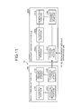
- FIG. 6 is a block diagram illustrating example functional elements of the image forming apparatus 100 and the delivery server apparatus 200 according to the first embodiment.
- the image forming apparatus 100 includes a UI (User Interface) control portion 110, an operating-and-display portion 120, a reading control portion 130, and a communication portion 140.
- UI control portion 110 and the reading control portion 130 may be implemented in software (program) or in a hardware circuit.
- the UI control portion 110 controls input processing and display processing of the operating-and-display portion 120. For instance, responsive to user's operation on the operating-and-display portion 120, the UI control portion 110 accepts a request for scanning a manuscript where handwritten proof correction is made by a proofreader, a request for transmitting image data generated by the scan, and the like. The UI control portion 110 also performs control for displaying, on the operating-and-display portion 120, a result of processing performed responsive to user's operation.
- the operating-and-display portion 120 displays a variety of information under control of the UI control portion 110.
- the operating-and-display portion 120 may include a Liquid Crystal Display (LCD) having a touch panel function or the like. For instance, the operating-and-display portion 120 displays a variety of information, such as a menu for image processing and a result of processing, under control of the UI control portion 110.
- LCD Liquid Crystal Display
- the reading control portion 130 controls scanning of a manuscript and the like. For instance, when a request for scanning a manuscript is accepted by the UI control portion 110, the reading control portion 130 controls scanning of the manuscript.
- the scan-requested manuscript is a manuscript where handwritten proof correction is made by a proofreader.
- the reading control portion 130 performs control of transmitting image data obtained by the scan to the delivery server apparatus 200 via the communication portion 140.
- the image data generated by scanning the manuscript which represent one or more manuscript images and on which handwritten proof correction is made by the proofreader, is thus transmitted to the delivery server apparatus 200.
- the communication portion 140 transmits and receives a variety of information. For instance, the communication portion 140 transmits image data to the delivery server apparatus 200 under control of the reading control portion 130.
- the delivery server apparatus 200 includes a communication portion 210, a detection portion 220, a generation portion 230, and a delivery control portion 240.
- a part or all of the detection portion 220, the generation portion 230, and the delivery control portion 240 may be implemented in software (program) or in a hardware circuit.
- the communication portion 210 transmits and receives a variety of information. For instance, the communication portion 210 transmits image data transmitted from the image forming apparatus 100. For another instance, the communication portion 210 transmits an electronic file to the PC 80 or the management server apparatus 300 under control of the delivery control portion 240.
- the detection portion 220 performs, for each page of image data representing one or more manuscript images, detection of a proof-correction indication image, which indicates that the page has proof-correction information. For instance, the detection portion 220 performs, for each page of image data received by the communication portion 210, detection of a marked checkbox (see FIG. 2 ), which indicates that the page has proof-correction information. Thereafter, the detection portion 220 outputs the image data together with a page number(s) of the page(s) where the marked checkbox is detected to the generation portion 230.
- the generation portion 230 generates output information, in which link information is added to the image data. For instance, the generation portion 230 generates an electronic file (see FIG. 3 ), in which link information for displaying the page(s) where the marked checkbox is detected is added to the image data on the basis of the page number(s) output from the detection portion 220. The generation portion 230 outputs the generated electronic file to the delivery control portion 240.
- the delivery control portion 240 performs control of delivering the output information. For instance, the delivery control portion 240 performs control of transmitting the electronic file generated by the generation portion 230 to the PC 80, the management server apparatus 300, or the like via the communication portion 210.
- the manuscript manager corrects errors in the not-proofread manuscript with reference to the electronic file, in which the link information is added.
- FIG. 7 is a sequence diagram illustrating an example of the delivery process sequence according to the first embodiment.
- the image forming apparatus 100 accepts an operation for performing scanning of a manuscript where handwritten proof correction is made by a proofreader (step S101) and performs scanning of the manuscript (step S102).
- the image forming apparatus 100 transmits a scan image obtained by the scan to the delivery server apparatus 200 (step S103).
- the scan image is image data containing proof-correction information, a checkbox indicating whether or not proof-correction information is contained, and the like.
- the delivery server apparatus 200 Upon receiving the image data from the image forming apparatus 100, the delivery server apparatus 200 performs, for each page of the image data, detection of a marked checkbox, which indicates that the page has proof-correction information (step S104). The delivery server apparatus 200 generates an electronic file, in which link information for displaying the page(s) where the marked checkbox is detected is added to the image data (step S105). Thereafter, the delivery server apparatus 200 delivers the generated electronic file to the PC 80, the management server apparatus 300, or the like (step S106).
- the delivery system 1 performs, for each page of image data obtained by scanning a manuscript where handwritten proof correction is made, detection of a proof-correction indication image, which indicates that the page has proof-correction information, and generates an electronic file, in which link information for displaying the page(s) where the proof-correction indication image is detected is added to the image data. Accordingly, the delivery system 1 can reduce oversights in a proofreading process.
- the detection as to whether proof-correction information is contained may alternatively be performed by detecting a difference between image data obtained by scanning a manuscript where handwritten proof correction is made by a proofreader and image data obtained by scanning a not-proofread manuscript.
- detecting a difference between image data obtained by scanning a proofread manuscript and image data obtained by scanning a not-proofread manuscript and generating an electronic file where link information for displaying the page(s) where the difference is detected is added to the image data are described.
- FIG. 8 is a block diagram illustrating example functional elements of an image forming apparatus 100a and a delivery server apparatus 200a according to the second embodiment.
- functional elements similar to those of the apparatuses according to the first embodiment are denoted by like reference numerals and detailed description thereof may be omitted.
- functions of the portions other than a reading control portion 130a, a detection portion 220a, and a generation portion 230a, which are described below, are similar to those of the first embodiment.
- the image forming apparatus 100a includes the UI control portion 110, the operating-and-display portion 120, the reading control portion 130a, and the communication portion 140.
- a part or all of the UI control portion 110 and the reading control portion 130a may be implemented in software (program) or in a hardware circuit.
- the reading control portion 130a controls scanning of a manuscript and the like.
- scan-requested manuscripts are a manuscript where handwritten proof correction is made by a proofreader and a not-proofread manuscript is requested. It is assumed that none of these manuscripts contains a checkbox or the like that is to be marked when proof correction is made.
- the not-proofread manuscript is sometimes referred to as "the first manuscript”
- the manuscript where handwritten proof correction is made by a proofreader is sometimes referred to as "the second manuscript”.
- Manuscript image data generated by scanning the first manuscript is sometimes referred to as "first image data”
- manuscript image data generated by scanning the second manuscript is sometimes referred to as "second image data”.
- the reading control portion 130a controls scanning of the first manuscript and the second manuscript.
- the reading control portion 130a performs control of transmitting the first image data (data representing one or more manuscript images) and the second image data (data representing the manuscript images and containing proof-correction information) obtained by the scan to the delivery server apparatus 200a via the communication portion 140.
- the delivery server apparatus 200a includes the communication portion 210, the detection portion 220a, the generation portion 230a, and the delivery control portion 240.
- a part or all of the detection portion 220a, the generation portion 230a, and the delivery control portion 240 may be implemented in software (program) or in a hardware circuit.
- the detection portion 220a detects a difference between the first image data and the second image data. For instance, the detection portion 220a detects a difference between the first image data and the second image data received by the communication portion 210 using a "diff" program or the like. The detection portion 220a outputs the second image data together with a page number(s) of a page(s) where the difference is detected to the generation portion 230a.
- the generation portion 230a generates output information, in which link information is added to the second image data. For instance, the generation portion 230a generates an electronic file, in which link information for displaying the page(s) where the difference is detected is added to the second image data on the basis of the page number(s) output from the detection portion 220a.
- Example information of the electronic file generated by the generation portion 230a is similar to that illustrated in FIG. 3 .
- the output information generated by the generation portion 230a may be configured to explicitly indicate a region(s) containing the difference detected by the detection portion 220a.
- the region may be one of regions, into which a single page is divided as desired. However, it is preferable that the region is changed depending on a type of the manuscript (e.g., vertical writing or horizontal writing) and/or an amount of information per page.
- the detection portion 220a outputs, in addition to the second image data and the page number(s), location information concerning the detected difference (i.e., information about location of the difference in the page) to the generation portion 230a.
- the generation portion 230a stores location information concerning the divided regions in advance. When location information concerning the difference detected by the detection portion 220a is included in the stored location information concerning the regions, the generation portion 230a generates an electronic file explicitly indicating the region containing the difference.
- FIG. 9 is a diagram illustrating example information of the electronic file generated by the delivery server apparatus 200a according to the second embodiment.
- link information e.g., "Page 3" and "Page 7" for displaying the page(s) containing the proof-correction information is added in the electronic file generated by the delivery server apparatus 200a so that, when the link information is selected, the page containing the proof-correction information is displayed.
- a region (frame) containing the proof-correction information is explicitly indicated.
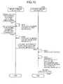
- FIG. 10 is a sequence diagram illustrating an example of the delivery process sequence according to the second embodiment.
- the image forming apparatus 100a accepts an operation for performing scanning of the first manuscript, which is a not-proofread manuscript, (step S201) and performs scanning of the first manuscript (step S202). The image forming apparatus 100a thus generates the first image data.
- the image forming apparatus 100a accepts an operation for performing scanning of the second manuscript, which is a manuscript where handwritten proof correction is made by a proofreader, (step S203) and performs scanning of the second manuscript (step S204).
- the image forming apparatus 100a thus generates the second image data.
- the image forming apparatus 100a transmits scan images (the first image data and the second image data) obtained by the scan to the delivery server apparatus 200a (step S205).
- the delivery server apparatus 200a Upon receiving the first image data and the second image data from the image forming apparatus 100a, the delivery server apparatus 200a detects a difference between the first image data and the second image data (step S206). The delivery server apparatus 200a generates an electronic file, in which link information for displaying the page(s) where the difference is detected and a region(s) (difference region(s)) containing a position where the difference is detected are added to the second image data (step S207). Thereafter, the delivery server apparatus 200a delivers the generated electronic file to the PC 80, the management server apparatus 300, or the like (step S208).
- a delivery system 1a detects a difference between the first image data, which is data representing one or more manuscript images, and the second image data, which is data representing the manuscript images and containing proof-correction information, and generates an electronic file where link information for displaying a page(s) where the difference is detected are added to the second image data. Accordingly, the delivery system 1a can reduce oversights in a proofreading process. Furthermore, because the electronic file generated by the delivery system 1a explicitly indicates a region(s) containing the detected difference, the delivery system 1a can further reduce oversights in the proofreading process. For instance, explicitly indicating regions each containing a difference is advantageous in a situation where a single page has a plurality of proof-correction information pieces.
- a difference between the first image data obtained by scanning a not-proofread manuscript and the second image data obtained by scanning a proofread manuscript is detected.
- the first image data to be used may be generated in advance.
- acquiring the first image data using storage location information indicating location where the first image data generated in advance is stored and detecting a difference between the acquired first image data and the second image data are described.
- FIG. 11 is a block diagram illustrating example functional elements of the image forming apparatus 100 and a delivery server apparatus 200b according to the third embodiment.
- functional elements similar to those of the apparatuses according to the first and second embodiments are denoted by like reference numerals and detailed description thereof may be omitted.
- functions of the portions other than a detection portion 220b and an acquisition portion 250b, which are described below, are similar to those of the first and second embodiments.
- the image forming apparatus 100 includes the UI control portion 110, the operating-and-display portion 120, the reading control portion 130, and the communication portion 140.
- a part or all of the UI control portion 110 and the reading control portion 130 may be implemented in software (program) or in a hardware circuit.
- the delivery server apparatus 200b includes the communication portion 210, the detection portion 220b, the generation portion 230a, the delivery control portion 240, and the acquisition portion 250b.
- a part or all of the detection portion 220b, the generation portion 230a, the delivery control portion 240, and the acquisition portion 250b may be implemented in software (program) or in a hardware circuit.
- the acquisition portion 250b acquires the first image data using storage location information indicating location where the first image data is stored. Description below is made on an assumption that the first image data is stored in the management server apparatus 300. For instance, when the second image data is received by the communication portion 210, the acquisition portion 250b acquires, via the communication portion 210, the first image data from the management server apparatus 300 using a URL (Uniform Resource Locator) indicating location where the first image data is stored in the management server apparatus 300.
- the URL information may be contained at a desired position in the second image data or, alternatively, may be provided by a user by entering the URL.
- the manuscript manager can use the PC 80 or the like to add the URL to the second image data.
- the acquisition portion 250b outputs the acquired first image data and the received second image data to the detection portion 220b.
- the detection portion 220b detects a difference between the first image data and the second image data. For instance, the detection portion 220b detects the difference between the first image data and the second image data output from the acquisition portion 250b using a "diff" program or the like. The detection portion 220b outputs the second image data together with a page number(s) of a page(s) where the difference is detected to the generation portion 230a.
- the generation portion 230a generates an electronic file (see FIG. 3 ), in which link information for displaying the page(s) where the difference is detected is added to the second image data on the basis of the page number(s) output from the detection portion 220b.
- the electric file (see FIG. 9 ) generated by the generation portion 230a may explicitly indicate a region(s) containing the difference detected by the detection portion 220b as in the case of the second embodiment.
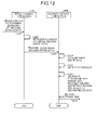
- FIG. 12 is a sequence diagram illustrating an example of the delivery process sequence according to the third embodiment.
- the image forming apparatus 100 accepts an operation for performing scanning of the second manuscript, which is a manuscript where handwritten proof correction is made by a proofreader, (step S301) and performs scanning of the second manuscript (step S302).
- the image forming apparatus 100 thus generates the second image data.
- the image forming apparatus 100 transmits a scan image (the second image data) obtained by the scan to the delivery server apparatus 200b (step S303).
- the delivery server apparatus 200b Upon receiving the second image data from the image forming apparatus 100, the delivery server apparatus 200b acquires the first image data from the management server apparatus 300 or the like using the URL (step S304). The delivery server apparatus 200b detects a difference between the acquired first image data and the received second image data (step S305). Thereafter, the delivery server apparatus 200b generates an electronic file, in which link information for displaying the page(s) where the difference is detected and a region(s) (difference region(s)) containing a position where the difference is detected are added to the second image data (step S306). Thereafter, the delivery server apparatus 200b delivers the generated electronic file to the PC 80, the management server apparatus 300, or the like (step S307).
- a delivery system 1b acquires the first image data using a URL indicating location where the first image data is stored, detects a difference between the first image data and the second image data, and generates an electronic file, in which link information for displaying a page(s) where the difference is detected are added to the second image data. Accordingly, the delivery system 1b can reduce oversights in a proofreading process.
- Embodiments of delivery system according to aspects of the present invention have been described above.
- the delivery system may be implemented in various ways other than the above-described embodiments.
- Embodiments that differ from the above-described embodiments in (1) Configuration and (2) Program are described below.
- Each of programs to be executed by the image forming apparatus 100 and the delivery server apparatus 200 may be provided in a form of being recorded in a computer-readable recording medium, such as a CD-ROM, a flexible disk (FD), a CD-R, and a DVD (Digital Versatile Disk) as an installable file or executable file.
- a computer-readable recording medium such as a CD-ROM, a flexible disk (FD), a CD-R, and a DVD (Digital Versatile Disk) as an installable file or executable file.
- Each of the programs to be executed by the image forming apparatus 100 and the delivery server apparatus 200 may be configured to be stored in a computer connected to a network, such as the Internet, and provided by being downloaded over the network.
- Each of the programs to be executed by the image forming apparatus 100 and the delivery server apparatus 200 can be configured to be provided or delivered via a network, such as the Internet.
- Each of the programs to be executed by the image forming apparatus 100 and the delivery server apparatus 200 may be configured to be provided as
- the program to be executed by the image forming apparatus 100 has a modular configuration including the reading control portion 130 described above. From an actual hardware perspective, the CPU reads out the program from a recording medium and executes it to load the reading control portion 130 into a main memory, thereby generating the reading control portion 130 on the main memory.
- the program to be executed by the delivery server apparatus 200 has a modular configuration including the above-described portions (the detection portion 220, the generation portion 230, and the delivery control portion 240). From an actual hardware perspective, the CPU reads out the program from a recording medium and executes it to load the above-described portions into a main memory, thereby generating the detection portion 220, the generation portion 230, and the delivery control portion 240 on the main memory.
- any of the above-described apparatus, devices or units can be implemented as a hardware apparatus, such as a special-purpose circuit or device, or as a hardware/software combination, such as a processor executing a software program.
- any one of the above-described and other methods of the present invention may be embodied in the form of a computer program stored in any kind of storage medium.
- storage mediums include, but are not limited to, flexible disk, hard disk, optical discs, magneto-optical discs, magnetic tapes, nonvolatile memory, semiconductor memory, read-only-memory (ROM), etc.
- any one of the above-described and other methods of the present invention may be implemented by an application specific integrated circuit (ASIC), a digital signal processor (DSP) or a field programmable gate array (FPGA), prepared by interconnecting an appropriate network of conventional component circuits or by a combination thereof with one or more conventional general purpose microprocessors or signal processors programmed accordingly.
- ASIC application specific integrated circuit
- DSP digital signal processor
- FPGA field programmable gate array
Landscapes
- Engineering & Computer Science (AREA)
- Multimedia (AREA)
- Computer Vision & Pattern Recognition (AREA)
- Theoretical Computer Science (AREA)
- Signal Processing (AREA)
- General Engineering & Computer Science (AREA)
- General Physics & Mathematics (AREA)
- Physics & Mathematics (AREA)
- Artificial Intelligence (AREA)
- Computing Systems (AREA)
- Health & Medical Sciences (AREA)
- Audiology, Speech & Language Pathology (AREA)
- Computational Linguistics (AREA)
- General Health & Medical Sciences (AREA)
- Facsimiles In General (AREA)
- Editing Of Facsimile Originals (AREA)
Abstract
Description
- The present invention relates generally to delivery server apparatuses, delivery methods, and delivery systems.
- Delivery systems that deliver a variety of electronic data, such as a scan image, captured image, and print image, are conventionally known. A system configured to make annotations on an electronic document shared by a plurality of users on a network is disclosed in Patent Document 1 (Japanese Laid-open Patent Publication No.
2012-029127 - Process of detecting and correcting errors in a manuscript (hereinafter, sometimes referred to as "proofreading" or "proof correction") in the publishing industry is performed through the following procedure, for example. A publisher prints a digitized not-proofread manuscript and sends the thus-printed not-proofread manuscript (hereinafter, "proof") to an outsource service company providing a service of performing a proofreading process. The outsource service company makes handwritten proof correction on the proof and sends the proofread manuscript (i.e., the proof, to which handwritten proof-correction information is added) to the publisher. The publisher digitizes the proof, to which the proof-correction information is added, into an electronic form and stores it in a server or the like. Thereafter, the publisher corrects errors on the digitized not-proofread manuscript with reference to the digitized proof, to which the proof-correction information is added, thereby generating a proof-corrected manuscript.
- The above-described proofreading process in the publishing industry is disadvantageous in that a part of the proof-correction information can be overlooked when correcting the digitized not-proofread manuscript with reference to the digitized the proof, to which the proof-correction information is added. With the system disclosed in Patent Document 1, the annotations cannot be extracted from a scan image or the like because the annotations are added by a user by operating a UI (User Interface). Accordingly, it is difficult to reduce oversights in a proofreading process using the above-described conventional technique.
- Under the circumstances, there is a need for reducing oversights in a proofreading process.
- It is an object of the present invention to at least partially solve the problems in the conventional technology.
- According to exemplary embodiments of the present invention, there is provided a delivery server apparatus comprising: a detection portion configured to perform, for each page of image data representing one or more manuscript images, detection of a proof-correction indication image, the proof-correction indication image indicating that the page has proof-correction information; and a generation portion configured to generate output information where link information, the link information being for use in displaying a page where the proof-correction indication image is detected, is added to the image data.
- Exemplary embodiments of the present invention also provide a delivery method comprising: performing, for each page of image data representing one or more manuscript images, detection of a proof-correction indication image, the proof-correction indication image indicating that the page has proof-correction information; and generating output information where link information, the link information being for use in displaying a page where the proof-correction indication image is detected, is added to the image data.
- Exemplary embodiments of the present invention also provide a delivery server apparatus comprising: a detection portion configured to detect a difference between first image data, the first image data being data representing one or more manuscript images, and second image data, the second image data being data representing the manuscript images and containing proof-correction information; and a generation portion configured to generate output information where link information, the link information being for use in displaying a page where the difference is detected, is added to the second image data.
Exemplary embodiments of the present invention also provide a delivery method comprising: detecting a difference between first image data, the first image data being data representing one or more manuscript images, and second image data, the second image data being data representing the manuscript images and containing proof-correction information; and generating output information where link information, the link information being for use in displaying a page where the difference is detected, is added to the second image data. - Exemplary embodiments of the present invention also provide A delivery system including an image forming apparatus and a delivery server apparatus, the delivery system comprising: a reading control portion configured to control scanning of a manuscript containing handwritten proof correction; a detection portion configured to perform, for each page of image data representing one or more manuscript images obtained by scanning the manuscript, detection of a proof-correction indication image, the proof-correction indication image indicating that the page has proof-correction information; a generation portion configured to generate output information where link information, the link information being for use in displaying a page where the proof-correction indication image is detected, is added to the image data; and a delivery control portion configured to perform control of delivering the generated output information to an information processing apparatus.
- The above and other objects, features, advantages and technical and industrial significance of this invention will be better understood by reading the following detailed description of presently preferred embodiments of the invention, when considered in connection with the accompanying drawings.
-
-
FIG. 1 is a diagram illustrating an example system configuration of a delivery system according to a first embodiment; -
FIG. 2 is a diagram illustrating an example layout of a manuscript according to the first embodiment; -
FIG. 3 is a diagram illustrating example information of an electronic file generated by a delivery server apparatus according to the first embodiment; -
FIG. 4 is a block diagram illustrating an example hardware structure of an image forming apparatus according to the first embodiment; -
FIG. 5 is a block diagram illustrating an example hardware structure of the delivery server apparatus according to the first embodiment; -
FIG. 6 is a block diagram illustrating example functional elements of the image forming apparatus and the delivery server apparatus according to the first embodiment; -
FIG. 7 is a sequence diagram illustrating an example of a delivery process sequence according to the first embodiment; -
FIG. 8 is a block diagram illustrating example functional elements of an image forming apparatus and a delivery server apparatus according to a second embodiment; -
FIG. 9 is a diagram illustrating example information of an electronic file generated by the delivery server apparatus according to the second embodiment; -
FIG. 10 is a sequence diagram illustrating an example of a delivery process sequence according to the second embodiment; -
FIG. 11 is a block diagram illustrating example functional elements of the image forming apparatus and a delivery server apparatus according to a third embodiment; and -
FIG. 12 is a sequence diagram illustrating an example of a delivery process sequence according to the third embodiment. - The accompanying drawings are intended to depict exemplary embodiments of the present invention and should not be interpreted to limit the scope thereof. Identical or similar reference numerals designate identical or similar components throughout the various drawings.
- The terminology used herein is for the purpose of describing particular embodiments only and is not intended to be limiting of the present invention.
- As used herein, the singular forms "a", "an" and "the" are intended to include the plural forms as well, unless the context clearly indicates otherwise.
- In describing preferred embodiments illustrated in the drawings, specific terminology may be employed for the sake of clarity. However, the disclosure of this patent specification is not intended to be limited to the specific terminology so selected, and it is to be understood that each specific element includes all technical equivalents that have the same function, operate in a similar manner, and achieve a similar result.
- Exemplary embodiments according to the present invention are described below with reference to the accompanying drawings. The embodiments described below should not be construed as limiting the scope of the present invention. The embodiments can be combined as appropriate so long as no contradiction occurs.
- System Configuration
- A system configuration of a delivery system according to a first embodiment is described below with reference to
FIG. 1. FIG. 1 is a diagram illustrating an example system configuration of the delivery system according to the first embodiment. - As illustrated in
FIG. 1 , a delivery system 1 includes a PC (Personal Computer) 80, aprinter 90, ascanner 100, adelivery server apparatus 200, and amanagement server apparatus 300. Each of theprinter 90 and thescanner 100 of the delivery system 1 may be an image forming apparatus, such as an MFP (Multi-Function Peripheral), capable of providing a copier function, a scanner function, a facsimile function, and a printer function. Theprinter 90 and thescanner 100 may be embodied in a single apparatus (MFP). Hereinafter, thescanner 100 may be referred to as theimage forming apparatus 100 for convenience of description. The delivery system 1 according to the first embodiment can be used in a proofreading process of the publishing industry. - The PC 80 is operated by a manuscript manager, who is a user on publisher's side. The manuscript manager operates the PC 80, thereby causing the
printer 90 to print image data, which is data representing one or more manuscript images. The image data may be stored in the PC 80 or, alternatively, may be stored in themanagement server apparatus 300 managing various electronic files. When the image data is stored in themanagement server apparatus 300, the PC 80 acquires the image data from themanagement server apparatus 300 responsive to an operation performed by the manuscript manager. The not-proofread manuscript (paper media) (hereinafter, "proof") printed out by theprinter 90 contains a checkbox(es) that allows thedelivery server apparatus 200 to detect a page(s) where proof correction is made. -
FIG. 2 is a diagram illustrating an example layout of a manuscript according to the first embodiment. For instance, as illustrated in the upper panel ofFIG. 2 , each page of the proof printed out by theprinter 90 contains a checkbox to be marked by a proofreader when the proofreader makes proof correction. The element to be used is not limited to such a checkbox; any mark, symbol, numeric, character, or the like, or a combination of them may alternatively be used so long as it can indicate that proof correction is made on the page. The proof with the checkbox may be produced by causing theprinter 90 to perform printing using paper, on which the checkbox is preprinted, and a dedicated tray. Alternatively, the proof with the checkbox may be produced by generating image data containing the checkbox and causing theprinter 90 to print out the generated image data. The manuscript manager sends the proof (paper media) printed out by theprinter 90 to an outsource service company providing a service of performing a proofreading process. - A proofreader, who is a user on the outsource service company's side, receives the proof and makes handwritten proof correction on the proof. For instance, as illustrated in the lower panel of
FIG. 2 , the proofreader marks a portion where a possible error is detected with a line or the like, handwrites a correction candidate or the like, and marks the checkbox to indicate that proof correction is made on this page. The proofreader sends the proofread manuscript (paper media) to the publisher. - The manuscript manager receives the proofread manuscript (paper media) and performs scanning of the proofread manuscript using the
scanner 100. Thescanner 100 scans the proofread manuscript and transmits image data containing a proof-correction indication image(s) (i.e., the marked checkbox(es)), which indicates that the page where the proof-correction indication image resides has proof-correction information, to thedelivery server apparatus 200. Upon receiving the image data from thescanner 100, thedelivery server apparatus 200 performs, for each page of the image data, detection of the proof-correction indication image (the marked checkbox). Thedelivery server apparatus 200 generates output information (e.g., an electronic file) where link information for displaying the page(s) where the proof-correction indication image (the marked checkbox) is detected is added to the image data. When generating the electronic file, the checkbox (and a caption, such as "This page has proof correction") may be deleted. -
FIG. 3 is a diagram illustrating example information of the electronic file generated by thedelivery server apparatus 200 according to the first embodiment. As illustrated inFIG. 3 , link information (e.g., "Page 3" and "Page 7") for displaying the page(s) containing the proof-correction information is added in the electronic file generated by thedelivery server apparatus 200 so that, when the link information is selected, the page containing the proof-correction information is displayed.FIG. 3 illustrates an example of the electronic file, from which the checkbox and the like are deleted. Thedelivery server apparatus 200 transmits (delivers) the electronic file, in which the link information is added, to themanagement server apparatus 300. Thedelivery server apparatus 200 may transmit the electronic file, in which the link information is added, to thePC 80. - The
management server apparatus 300 manages the electronic file delivered by thedelivery server apparatus 200. ThePC 80 or the like acquires the electronic file managed by themanagement server apparatus 300 as necessary. The manuscript corrects errors in the digitized proof using the electronic file, in which the link information is added, by operating thePC 80 or the like. - In short, the delivery system 1 performs, for each page of image data obtained by scanning a manuscript where handwritten proof correction is made, detection of a proof-correction indication image, which indicates that the page contains proof-correction information, and generates an electronic file where link information for displaying the page(s) where the proof-correction indication image is detected is added to the image data. Hence, the delivery system 1 allows a manuscript manager to correct errors with reference to the electronic file, in which the link information is added, thereby reducing oversights in a proofreading process.
- A hardware structure of the
image forming apparatus 100 according to the first embodiment is described below with reference toFIG. 4. FIG. 4 is a block diagram illustrating an example hardware structure of theimage forming apparatus 100 according to the first embodiment. - As illustrated in
FIG. 4 , theimage forming apparatus 100 includes acontroller 10 and anengine section 60 that are connected via a PCI (Peripheral Component Interconnect) bus. Thecontroller 10 is a controller that controls the entireimage forming apparatus 100, drawing, communication, and various inputs. Theengine section 60 is a printer engine or the like connectable to the PCI bus. Examples of theengine section 60 include a black-and-white plotter, a one-drum color plotter, a four-drum color plotter, a scanner unit, and a facsimile unit. Theengine section 60 includes, in addition to what is referred to as an engine portion such as a plotter, a portion for image processing, such as error diffusion and gamma conversion. - The
controller 10 includes a CPU (Central Processing Unit) 11, a north bridge (NB) 13, a system memory (MEM-P) 12, a south bridge (SB) 14, a local memory (MEM-C) 17, an ASIC (Application-Specific Integrated Circuit) 16, and a Hard Disk Drive (HDD) 18, where thenorth bridge 13 and theASIC 16 are connected to each other via an AGP (Accelerated Graphics Port)bus 15. The MEM-P 12 includes a ROM (Read Only Memory) 12a and a RAM (Random Access Memory) 12b. - The
CPU 11 performs overall control of theimage forming apparatus 100 and includes a chip set including thenorth bridge 13, the MEM-P 12, and thesouth bridge 14. TheCPU 11 is connected to other devices via the chip set. Thenorth bridge 13 is a bridge for connecting theCPU 11 to the MEM-P 12, thesouth bridge 14, and theAGP bus 15. Thenorth bridge 13 includes a PCI master, an AGP target, and a memory controller that controls reading and writing from and to the MEM-P 12. - The MEM-
P 12 is a system memory for use as a memory where program instructions (hereinafter, "program") and data are to be stored, as a memory where program and data are to be loaded, and as a printer buffer memory and includes theROM 12a and theRAM 12b. TheROM 12a is a read only memory for use as the memory where program and data are to be stored. TheRAM 12b is a writable and readable memory for use as the memory where program and data are to be loaded and as the printer buffer memory. Thesouth bridge 14 is a bridge for connecting between thenorth bridge 13, and PCI devices and peripheral devices. Thesouth bridge 14 is connected to thenorth bridge 13 via the PCI bus. A network interface and the like are also connected to this PCI bus. - The
ASIC 16 is an IC (Integrated Circuit) for image processing and includes a hardware component for the image processing. TheASIC 16 functions as a bridge that connects between each of theAGP bus 15, the PCI bus, theHDD 18, and the MEM-C 17. TheASIC 16 includes a PCI target and an AGP master, an arbiter (ARB), which is a core of theASIC 16, a memory controller that controls the MEM-C 17, a plurality of DMACs (Direct Memory Access Controllers) that perform image rotation and the like by a hardware logic and the like, and a PCI unit that transfers data to and from theengine section 60 via the PCI bus. An FCU (Facsimile Control Unit) 30, a USB (Universal Serial Bus) 40, and an IEEE 1394 (the Institute of Electrical and Electronics Engineers 1394)interface 50 are connected to theASIC 16 via the PCI bus. An operating-and-display unit 20 is directly connected to theASIC 16. - The MEM-
C 17 is a local memory for use as an image buffer for copying and a code buffer. The HDD (Hard Disk Drive) 18 is a storage for accumulating image data, programs, font data, and forms. TheAGP bus 15 is a bus interface for a graphics accelerator card introduced for speedup of graphics processing and allows direct access to the MEM-P 12 with a high throughput, thereby increasing processing speed of the graphics accelerator card. - A hardware structure of the
delivery server apparatus 200 according to the first embodiment is described below with reference toFIG. 5. FIG. 5 is a block diagram illustrating an example hardware structure of thedelivery server apparatus 200 according to the first embodiment. - As illustrated in
FIG. 5 , thedelivery server apparatus 200 includes aCPU 22, aRAM 23, aROM 24, and a communication I/F 25. These components are mutually connected via asystem bus 21. - The
CPU 22 performs centralized control on operations of thedelivery server apparatus 200. TheCPU 22 performs the centralized control on the operations of thedelivery server apparatus 200 by executing, while using theRAM 23 as a work area, program stored in theROM 24 or the like. The communication I/F 25 is an interface that controls communications with thePC 80, theimage forming apparatus 100, themanagement server apparatus 300, and the like. - Functional elements of the apparatuses according to the first embodiment are described below with reference to
FIG. 6. FIG. 6 is a block diagram illustrating example functional elements of theimage forming apparatus 100 and thedelivery server apparatus 200 according to the first embodiment. - As illustrated in
FIG. 6 , theimage forming apparatus 100 includes a UI (User Interface)control portion 110, an operating-and-display portion 120, areading control portion 130, and acommunication portion 140. A part or all of theUI control portion 110 and thereading control portion 130 may be implemented in software (program) or in a hardware circuit. - The
UI control portion 110 controls input processing and display processing of the operating-and-display portion 120. For instance, responsive to user's operation on the operating-and-display portion 120, theUI control portion 110 accepts a request for scanning a manuscript where handwritten proof correction is made by a proofreader, a request for transmitting image data generated by the scan, and the like. TheUI control portion 110 also performs control for displaying, on the operating-and-display portion 120, a result of processing performed responsive to user's operation. The operating-and-display portion 120 displays a variety of information under control of theUI control portion 110. The operating-and-display portion 120 may include a Liquid Crystal Display (LCD) having a touch panel function or the like. For instance, the operating-and-display portion 120 displays a variety of information, such as a menu for image processing and a result of processing, under control of theUI control portion 110. - The
reading control portion 130 controls scanning of a manuscript and the like. For instance, when a request for scanning a manuscript is accepted by theUI control portion 110, thereading control portion 130 controls scanning of the manuscript. In the first embodiment, the scan-requested manuscript is a manuscript where handwritten proof correction is made by a proofreader. Thereafter, thereading control portion 130 performs control of transmitting image data obtained by the scan to thedelivery server apparatus 200 via thecommunication portion 140. The image data generated by scanning the manuscript, which represent one or more manuscript images and on which handwritten proof correction is made by the proofreader, is thus transmitted to thedelivery server apparatus 200. - The
communication portion 140 transmits and receives a variety of information. For instance, thecommunication portion 140 transmits image data to thedelivery server apparatus 200 under control of thereading control portion 130. - As illustrated in
FIG. 6 , thedelivery server apparatus 200 includes acommunication portion 210, adetection portion 220, ageneration portion 230, and adelivery control portion 240. A part or all of thedetection portion 220, thegeneration portion 230, and thedelivery control portion 240 may be implemented in software (program) or in a hardware circuit. - The
communication portion 210 transmits and receives a variety of information. For instance, thecommunication portion 210 transmits image data transmitted from theimage forming apparatus 100. For another instance, thecommunication portion 210 transmits an electronic file to thePC 80 or themanagement server apparatus 300 under control of thedelivery control portion 240. - The
detection portion 220 performs, for each page of image data representing one or more manuscript images, detection of a proof-correction indication image, which indicates that the page has proof-correction information. For instance, thedetection portion 220 performs, for each page of image data received by thecommunication portion 210, detection of a marked checkbox (seeFIG. 2 ), which indicates that the page has proof-correction information. Thereafter, thedetection portion 220 outputs the image data together with a page number(s) of the page(s) where the marked checkbox is detected to thegeneration portion 230. - The
generation portion 230 generates output information, in which link information is added to the image data. For instance, thegeneration portion 230 generates an electronic file (seeFIG. 3 ), in which link information for displaying the page(s) where the marked checkbox is detected is added to the image data on the basis of the page number(s) output from thedetection portion 220. Thegeneration portion 230 outputs the generated electronic file to thedelivery control portion 240. - The
delivery control portion 240 performs control of delivering the output information. For instance, thedelivery control portion 240 performs control of transmitting the electronic file generated by thegeneration portion 230 to thePC 80, themanagement server apparatus 300, or the like via thecommunication portion 210. The manuscript manager corrects errors in the not-proofread manuscript with reference to the electronic file, in which the link information is added. - A delivery process sequence according to the first embodiment is described below with reference to
FIG. 7. FIG. 7 is a sequence diagram illustrating an example of the delivery process sequence according to the first embodiment. - As illustrated in
FIG. 7 , theimage forming apparatus 100 accepts an operation for performing scanning of a manuscript where handwritten proof correction is made by a proofreader (step S101) and performs scanning of the manuscript (step S102). Theimage forming apparatus 100 transmits a scan image obtained by the scan to the delivery server apparatus 200 (step S103). The scan image is image data containing proof-correction information, a checkbox indicating whether or not proof-correction information is contained, and the like. - Upon receiving the image data from the
image forming apparatus 100, thedelivery server apparatus 200 performs, for each page of the image data, detection of a marked checkbox, which indicates that the page has proof-correction information (step S104). Thedelivery server apparatus 200 generates an electronic file, in which link information for displaying the page(s) where the marked checkbox is detected is added to the image data (step S105). Thereafter, thedelivery server apparatus 200 delivers the generated electronic file to thePC 80, themanagement server apparatus 300, or the like (step S106). - The delivery system 1 according to the first embodiment performs, for each page of image data obtained by scanning a manuscript where handwritten proof correction is made, detection of a proof-correction indication image, which indicates that the page has proof-correction information, and generates an electronic file, in which link information for displaying the page(s) where the proof-correction indication image is detected is added to the image data. Accordingly, the delivery system 1 can reduce oversights in a proofreading process.
- In the first embodiment described above, for each page of image data, whether the page contains proof-correction information is detected by scanning a manuscript containing a checkbox(es) that is to be marked by a proofreader when the proofreader makes handwritten proof correction. The detection as to whether proof-correction information is contained may alternatively be performed by detecting a difference between image data obtained by scanning a manuscript where handwritten proof correction is made by a proofreader and image data obtained by scanning a not-proofread manuscript. In a second embodiment, detecting a difference between image data obtained by scanning a proofread manuscript and image data obtained by scanning a not-proofread manuscript and generating an electronic file where link information for displaying the page(s) where the difference is detected is added to the image data are described.
- Functional elements of apparatuses according to the second embodiment are described below with reference to
FIG. 8. FIG. 8 is a block diagram illustrating example functional elements of animage forming apparatus 100a and adelivery server apparatus 200a according to the second embodiment. In the second embodiment, functional elements similar to those of the apparatuses according to the first embodiment are denoted by like reference numerals and detailed description thereof may be omitted. Specifically, functions of the portions other than areading control portion 130a, adetection portion 220a, and ageneration portion 230a, which are described below, are similar to those of the first embodiment. - As illustrated in
FIG. 8 , theimage forming apparatus 100a includes theUI control portion 110, the operating-and-display portion 120, thereading control portion 130a, and thecommunication portion 140. A part or all of theUI control portion 110 and thereading control portion 130a may be implemented in software (program) or in a hardware circuit. - The
reading control portion 130a controls scanning of a manuscript and the like. In the second embodiment, scan-requested manuscripts are a manuscript where handwritten proof correction is made by a proofreader and a not-proofread manuscript is requested. It is assumed that none of these manuscripts contains a checkbox or the like that is to be marked when proof correction is made. Hereinafter, the not-proofread manuscript is sometimes referred to as "the first manuscript", whereas the manuscript where handwritten proof correction is made by a proofreader is sometimes referred to as "the second manuscript". Manuscript image data generated by scanning the first manuscript is sometimes referred to as "first image data", whereas manuscript image data generated by scanning the second manuscript is sometimes referred to as "second image data". When a request for scanning the first manuscript and the second manuscript is accepted by theUI control portion 110, thereading control portion 130a controls scanning of the first manuscript and the second manuscript. Thereading control portion 130a performs control of transmitting the first image data (data representing one or more manuscript images) and the second image data (data representing the manuscript images and containing proof-correction information) obtained by the scan to thedelivery server apparatus 200a via thecommunication portion 140. - As illustrated in
FIG. 8 , thedelivery server apparatus 200a includes thecommunication portion 210, thedetection portion 220a, thegeneration portion 230a, and thedelivery control portion 240. A part or all of thedetection portion 220a, thegeneration portion 230a, and thedelivery control portion 240 may be implemented in software (program) or in a hardware circuit. - The
detection portion 220a detects a difference between the first image data and the second image data. For instance, thedetection portion 220a detects a difference between the first image data and the second image data received by thecommunication portion 210 using a "diff" program or the like. Thedetection portion 220a outputs the second image data together with a page number(s) of a page(s) where the difference is detected to thegeneration portion 230a. - The
generation portion 230a generates output information, in which link information is added to the second image data. For instance, thegeneration portion 230a generates an electronic file, in which link information for displaying the page(s) where the difference is detected is added to the second image data on the basis of the page number(s) output from thedetection portion 220a. Example information of the electronic file generated by thegeneration portion 230a is similar to that illustrated inFIG. 3 . - The output information generated by the
generation portion 230a may be configured to explicitly indicate a region(s) containing the difference detected by thedetection portion 220a. The region may be one of regions, into which a single page is divided as desired. However, it is preferable that the region is changed depending on a type of the manuscript (e.g., vertical writing or horizontal writing) and/or an amount of information per page. Specifically, thedetection portion 220a outputs, in addition to the second image data and the page number(s), location information concerning the detected difference (i.e., information about location of the difference in the page) to thegeneration portion 230a. Thegeneration portion 230a stores location information concerning the divided regions in advance. When location information concerning the difference detected by thedetection portion 220a is included in the stored location information concerning the regions, thegeneration portion 230a generates an electronic file explicitly indicating the region containing the difference. -
FIG. 9 is a diagram illustrating example information of the electronic file generated by thedelivery server apparatus 200a according to the second embodiment. As illustrated inFIG. 9 , link information (e.g., "Page 3" and "Page 7") for displaying the page(s) containing the proof-correction information is added in the electronic file generated by thedelivery server apparatus 200a so that, when the link information is selected, the page containing the proof-correction information is displayed. A region (frame) containing the proof-correction information is explicitly indicated. - A delivery process sequence according to the second embodiment is described below with reference to
FIG. 10. FIG. 10 is a sequence diagram illustrating an example of the delivery process sequence according to the second embodiment. - As illustrated in
FIG. 10 , theimage forming apparatus 100a accepts an operation for performing scanning of the first manuscript, which is a not-proofread manuscript, (step S201) and performs scanning of the first manuscript (step S202). Theimage forming apparatus 100a thus generates the first image data. Theimage forming apparatus 100a accepts an operation for performing scanning of the second manuscript, which is a manuscript where handwritten proof correction is made by a proofreader, (step S203) and performs scanning of the second manuscript (step S204). Theimage forming apparatus 100a thus generates the second image data. Theimage forming apparatus 100a transmits scan images (the first image data and the second image data) obtained by the scan to thedelivery server apparatus 200a (step S205). - Upon receiving the first image data and the second image data from the
image forming apparatus 100a, thedelivery server apparatus 200a detects a difference between the first image data and the second image data (step S206). Thedelivery server apparatus 200a generates an electronic file, in which link information for displaying the page(s) where the difference is detected and a region(s) (difference region(s)) containing a position where the difference is detected are added to the second image data (step S207). Thereafter, thedelivery server apparatus 200a delivers the generated electronic file to thePC 80, themanagement server apparatus 300, or the like (step S208). - A
delivery system 1a according to the second embodiment detects a difference between the first image data, which is data representing one or more manuscript images, and the second image data, which is data representing the manuscript images and containing proof-correction information, and generates an electronic file where link information for displaying a page(s) where the difference is detected are added to the second image data. Accordingly, thedelivery system 1a can reduce oversights in a proofreading process. Furthermore, because the electronic file generated by thedelivery system 1a explicitly indicates a region(s) containing the detected difference, thedelivery system 1a can further reduce oversights in the proofreading process. For instance, explicitly indicating regions each containing a difference is advantageous in a situation where a single page has a plurality of proof-correction information pieces. - In the second embodiment described above, a difference between the first image data obtained by scanning a not-proofread manuscript and the second image data obtained by scanning a proofread manuscript is detected. Alternatively, the first image data to be used may be generated in advance. In a third embodiment, acquiring the first image data using storage location information indicating location where the first image data generated in advance is stored and detecting a difference between the acquired first image data and the second image data are described.
- Functional elements of apparatuses according to the third embodiment are described below with reference to
FIG. 11. FIG. 11 is a block diagram illustrating example functional elements of theimage forming apparatus 100 and adelivery server apparatus 200b according to the third embodiment. In the third embodiment, functional elements similar to those of the apparatuses according to the first and second embodiments are denoted by like reference numerals and detailed description thereof may be omitted. Specifically, functions of the portions other than adetection portion 220b and anacquisition portion 250b, which are described below, are similar to those of the first and second embodiments. - As illustrated in
FIG. 11 , theimage forming apparatus 100 includes theUI control portion 110, the operating-and-display portion 120, thereading control portion 130, and thecommunication portion 140. A part or all of theUI control portion 110 and thereading control portion 130 may be implemented in software (program) or in a hardware circuit. - As illustrated in
FIG. 11 , thedelivery server apparatus 200b includes thecommunication portion 210, thedetection portion 220b, thegeneration portion 230a, thedelivery control portion 240, and theacquisition portion 250b. A part or all of thedetection portion 220b, thegeneration portion 230a, thedelivery control portion 240, and theacquisition portion 250b may be implemented in software (program) or in a hardware circuit. - The
acquisition portion 250b acquires the first image data using storage location information indicating location where the first image data is stored. Description below is made on an assumption that the first image data is stored in themanagement server apparatus 300. For instance, when the second image data is received by thecommunication portion 210, theacquisition portion 250b acquires, via thecommunication portion 210, the first image data from themanagement server apparatus 300 using a URL (Uniform Resource Locator) indicating location where the first image data is stored in themanagement server apparatus 300. The URL information may be contained at a desired position in the second image data or, alternatively, may be provided by a user by entering the URL. When the URL information is to be contained at the desired position in the second image data, the manuscript manager can use thePC 80 or the like to add the URL to the second image data. Theacquisition portion 250b outputs the acquired first image data and the received second image data to thedetection portion 220b. - The
detection portion 220b detects a difference between the first image data and the second image data. For instance, thedetection portion 220b detects the difference between the first image data and the second image data output from theacquisition portion 250b using a "diff" program or the like. Thedetection portion 220b outputs the second image data together with a page number(s) of a page(s) where the difference is detected to thegeneration portion 230a. Thegeneration portion 230a generates an electronic file (seeFIG. 3 ), in which link information for displaying the page(s) where the difference is detected is added to the second image data on the basis of the page number(s) output from thedetection portion 220b. The electric file (seeFIG. 9 ) generated by thegeneration portion 230a may explicitly indicate a region(s) containing the difference detected by thedetection portion 220b as in the case of the second embodiment. - A delivery process sequence according to the third embodiment is described below with reference to
FIG. 12. FIG. 12 is a sequence diagram illustrating an example of the delivery process sequence according to the third embodiment. - As illustrated in
FIG. 12 , theimage forming apparatus 100 accepts an operation for performing scanning of the second manuscript, which is a manuscript where handwritten proof correction is made by a proofreader, (step S301) and performs scanning of the second manuscript (step S302). Theimage forming apparatus 100 thus generates the second image data. Theimage forming apparatus 100 transmits a scan image (the second image data) obtained by the scan to thedelivery server apparatus 200b (step S303). - Upon receiving the second image data from the
image forming apparatus 100, thedelivery server apparatus 200b acquires the first image data from themanagement server apparatus 300 or the like using the URL (step S304). Thedelivery server apparatus 200b detects a difference between the acquired first image data and the received second image data (step S305). Thereafter, thedelivery server apparatus 200b generates an electronic file, in which link information for displaying the page(s) where the difference is detected and a region(s) (difference region(s)) containing a position where the difference is detected are added to the second image data (step S306). Thereafter, thedelivery server apparatus 200b delivers the generated electronic file to thePC 80, themanagement server apparatus 300, or the like (step S307). - A
delivery system 1b according to the third embodiment acquires the first image data using a URL indicating location where the first image data is stored, detects a difference between the first image data and the second image data, and generates an electronic file, in which link information for displaying a page(s) where the difference is detected are added to the second image data. Accordingly, thedelivery system 1b can reduce oversights in a proofreading process. - Embodiments of delivery system according to aspects of the present invention have been described above. The delivery system may be implemented in various ways other than the above-described embodiments. Embodiments that differ from the above-described embodiments in (1) Configuration and (2) Program are described below.
- The processing procedure, control procedure, specific names, and information including a variety of data and parameters presented above or in the drawings can be modified as desired unless otherwise specifically specified. The constituents of the illustrated apparatuses are functional concepts and do not necessarily require that they be physically configured as illustrated. Specific forms of distribution and integration of the apparatuses are not limited to those illustrated, and all or a part of the apparatuses can be functionally or physically distributed or integrated in any desired units depending on various loads, usage scenarios, and the like.
- Each of programs to be executed by the
image forming apparatus 100 and thedelivery server apparatus 200 may be provided in a form of being recorded in a computer-readable recording medium, such as a CD-ROM, a flexible disk (FD), a CD-R, and a DVD (Digital Versatile Disk) as an installable file or executable file. Each of the programs to be executed by theimage forming apparatus 100 and thedelivery server apparatus 200 may be configured to be stored in a computer connected to a network, such as the Internet, and provided by being downloaded over the network. Each of the programs to be executed by theimage forming apparatus 100 and thedelivery server apparatus 200 can be configured to be provided or delivered via a network, such as the Internet. Each of the programs to be executed by theimage forming apparatus 100 and thedelivery server apparatus 200 may be configured to be provided as being embedded in a ROM or the like in advance. - The program to be executed by the
image forming apparatus 100 has a modular configuration including thereading control portion 130 described above. From an actual hardware perspective, the CPU reads out the program from a recording medium and executes it to load thereading control portion 130 into a main memory, thereby generating thereading control portion 130 on the main memory. - The program to be executed by the
delivery server apparatus 200 has a modular configuration including the above-described portions (thedetection portion 220, thegeneration portion 230, and the delivery control portion 240). From an actual hardware perspective, the CPU reads out the program from a recording medium and executes it to load the above-described portions into a main memory, thereby generating thedetection portion 220, thegeneration portion 230, and thedelivery control portion 240 on the main memory. - According to an aspect of the present invention, oversights in a proofreading process can be reduced.
- The above-described embodiments are illustrative and do not limit the present invention. Thus, numerous additional modifications and variations are possible in light of the above teachings. For example, at least one element of different illustrative and exemplary embodiments herein may be combined with each other or substituted for each other within the scope of this disclosure and appended claims. Further, features of components of the embodiments, such as the number, the position, and the shape are not limited the embodiments and thus may be preferably set. It is therefore to be understood that within the scope of the appended claims, the disclosure of the present invention may be practiced otherwise than as specifically described herein.
- The method steps, processes, or operations described herein are not to be construed as necessarily requiring their performance in the particular order discussed or illustrated, unless specifically identified as an order of performance or clearly identified through the context. It is also to be understood that additional or alternative steps may be employed.
- Further, any of the above-described apparatus, devices or units can be implemented as a hardware apparatus, such as a special-purpose circuit or device, or as a hardware/software combination, such as a processor executing a software program.
- Further, as described above, any one of the above-described and other methods of the present invention may be embodied in the form of a computer program stored in any kind of storage medium. Examples of storage mediums include, but are not limited to, flexible disk, hard disk, optical discs, magneto-optical discs, magnetic tapes, nonvolatile memory, semiconductor memory, read-only-memory (ROM), etc.
- Alternatively, any one of the above-described and other methods of the present invention may be implemented by an application specific integrated circuit (ASIC), a digital signal processor (DSP) or a field programmable gate array (FPGA), prepared by interconnecting an appropriate network of conventional component circuits or by a combination thereof with one or more conventional general purpose microprocessors or signal processors programmed accordingly.
- Although the invention has been described with respect to specific embodiments for a complete and clear disclosure, the appended claims are not to be thus limited but are to be construed as embodying all modifications and alternative constructions that may occur to one skilled in the art that fairly fall within the basic teaching herein set forth.
Claims (7)
- A delivery server apparatus comprising:a detection portion configured to perform, for each page of image data representing one or more manuscript images, detection of a proof-correction indication image, the proof-correction indication image indicating that the page has proof-correction information; anda generation portion configured to generate output information where link information, the link information being for use in displaying a page where the proof-correction indication image is detected, is added to the image data.
- A delivery method comprising:performing, for each page of image data representing one or more manuscript images, detection of a proof-correction indication image, the proof-correction indication image indicating that the page has proof-correction information; andgenerating output information where link information, the link information being for use in displaying a page where the proof-correction indication image is detected, is added to the image data.
- A delivery server apparatus comprising:a detection portion configured to detect a difference between first image data, the first image data being data representing one or more manuscript images, and second image data, the second image data being data representing the manuscript images and containing proof-correction information; anda generation portion configured to generate output information where link information, the link information being for use in displaying a page where the difference is detected, is added to the second image data.
- The delivery server apparatus according to claim 3, further comprising
an acquisition portion configured to acquire the first image data using storage location information indicating location where the first image data is stored, wherein
the detection portion detects a difference between the acquired first image data and the second image data. - The delivery server apparatus according to claim 3 or 4, wherein the output information generated by the generation portion explicitly indicates a region containing the detected difference, the region being one of regions into which a single page is divided as desired.
- A delivery method comprising:detecting a difference between first image data, the first image data being data representing one or more manuscript images, and second image data, the second image data being data representing the manuscript images and containing proof-correction information; andgenerating output information where link information, the link information being for use in displaying a page where the difference is detected, is added to the second image data.
- A delivery system including an image forming apparatus and a delivery server apparatus, the delivery system comprising:a reading control portion configured to control scanning of a manuscript containing handwritten proof correction;a detection portion configured to perform, for each page of image data representing one or more manuscript images obtained by scanning the manuscript, detection of a proof-correction indication image, the proof-correction indication image indicating that the page has proof-correction information;a generation portion configured to generate output information where link information, the link information being for use in displaying a page where the proof-correction indication image is detected, is added to the image data; anda delivery control portion configured to perform control of delivering the generated output information to an information processing apparatus.
Applications Claiming Priority (1)
| Application Number | Priority Date | Filing Date | Title |
|---|---|---|---|
| JP2015124974A JP2017011490A (en) | 2015-06-22 | 2015-06-22 | Distribution server device, distribution method, and distribution system |
Publications (1)
| Publication Number | Publication Date |
|---|---|
| EP3110123A1 true EP3110123A1 (en) | 2016-12-28 |
Family
ID=56497536
Family Applications (1)
| Application Number | Title | Priority Date | Filing Date |
|---|---|---|---|
| EP16175710.9A Ceased EP3110123A1 (en) | 2015-06-22 | 2016-06-22 | Detection of proof-correction information in manuscript images |
Country Status (2)
| Country | Link |
|---|---|
| EP (1) | EP3110123A1 (en) |
| JP (1) | JP2017011490A (en) |
Cited By (1)
| Publication number | Priority date | Publication date | Assignee | Title |
|---|---|---|---|---|
| US11095864B2 (en) | 2017-05-02 | 2021-08-17 | Interdigital Vc Holdings, Inc. | Method and device for color gamut mapping |
Citations (10)
| Publication number | Priority date | Publication date | Assignee | Title |
|---|---|---|---|---|
| US20050243358A1 (en) * | 2004-04-26 | 2005-11-03 | Peter Frings | Method and system for preparing a document for printing |
| US20060050967A1 (en) * | 2004-09-07 | 2006-03-09 | Dainippon Screen Mfg. Co., Ltd. | Image processing apparatus and program |
| US20060291727A1 (en) * | 2005-06-23 | 2006-12-28 | Microsoft Corporation | Lifting ink annotations from paper |
| US20070118795A1 (en) * | 2005-11-23 | 2007-05-24 | Peter Noyes | A Method of Processing Annotations Using an Editable Multi-Dimensional Catalog |
| US20080114782A1 (en) * | 2006-11-14 | 2008-05-15 | Microsoft Corporation | Integrating Analog Markups with Electronic Documents |
| US20080246975A1 (en) * | 2007-04-06 | 2008-10-09 | Xerox Corporation | Handwritten annotation recognition for copy jobs |
| US20080267534A1 (en) * | 2007-04-30 | 2008-10-30 | Sriganesh Madhvanath | Image-Processing System |
| US20090257098A1 (en) * | 2008-04-09 | 2009-10-15 | Sriganesh Madhvanath | Simplified Operation Of Scan And Print Devices |
| JP2012029127A (en) | 2010-07-26 | 2012-02-09 | Konica Minolta Business Technologies Inc | Service provision system and server |
| US20150146266A1 (en) * | 2013-11-28 | 2015-05-28 | Kyocera Document Solutions Inc. | Document reading device and image forming apparatus |
Family Cites Families (5)
| Publication number | Priority date | Publication date | Assignee | Title |
|---|---|---|---|---|
| JPH11272654A (en) * | 1998-03-20 | 1999-10-08 | Toshiba Corp | Document editing apparatus and method |
| JP2003296313A (en) * | 2002-04-05 | 2003-10-17 | Toppan Printing Co Ltd | Calibration device and calibration method |
| JP2006092100A (en) * | 2004-09-22 | 2006-04-06 | Fuji Xerox Co Ltd | Print server, print original calibration system and print original calibration method |
| JP2007325196A (en) * | 2006-06-05 | 2007-12-13 | Fuji Xerox Co Ltd | Device and method for managing document |
| JP2007335920A (en) * | 2006-06-12 | 2007-12-27 | Fuji Xerox Co Ltd | Image processing apparatus and image processing program |
-
2015
- 2015-06-22 JP JP2015124974A patent/JP2017011490A/en active Pending
-
2016
- 2016-06-22 EP EP16175710.9A patent/EP3110123A1/en not_active Ceased
Patent Citations (10)
| Publication number | Priority date | Publication date | Assignee | Title |
|---|---|---|---|---|
| US20050243358A1 (en) * | 2004-04-26 | 2005-11-03 | Peter Frings | Method and system for preparing a document for printing |
| US20060050967A1 (en) * | 2004-09-07 | 2006-03-09 | Dainippon Screen Mfg. Co., Ltd. | Image processing apparatus and program |
| US20060291727A1 (en) * | 2005-06-23 | 2006-12-28 | Microsoft Corporation | Lifting ink annotations from paper |
| US20070118795A1 (en) * | 2005-11-23 | 2007-05-24 | Peter Noyes | A Method of Processing Annotations Using an Editable Multi-Dimensional Catalog |
| US20080114782A1 (en) * | 2006-11-14 | 2008-05-15 | Microsoft Corporation | Integrating Analog Markups with Electronic Documents |
| US20080246975A1 (en) * | 2007-04-06 | 2008-10-09 | Xerox Corporation | Handwritten annotation recognition for copy jobs |
| US20080267534A1 (en) * | 2007-04-30 | 2008-10-30 | Sriganesh Madhvanath | Image-Processing System |
| US20090257098A1 (en) * | 2008-04-09 | 2009-10-15 | Sriganesh Madhvanath | Simplified Operation Of Scan And Print Devices |
| JP2012029127A (en) | 2010-07-26 | 2012-02-09 | Konica Minolta Business Technologies Inc | Service provision system and server |
| US20150146266A1 (en) * | 2013-11-28 | 2015-05-28 | Kyocera Document Solutions Inc. | Document reading device and image forming apparatus |
Cited By (1)
| Publication number | Priority date | Publication date | Assignee | Title |
|---|---|---|---|---|
| US11095864B2 (en) | 2017-05-02 | 2021-08-17 | Interdigital Vc Holdings, Inc. | Method and device for color gamut mapping |
Also Published As
| Publication number | Publication date |
|---|---|
| JP2017011490A (en) | 2017-01-12 |
Similar Documents
| Publication | Publication Date | Title |
|---|---|---|
| US8861001B2 (en) | Output control system, output control method, and output control apparatus for determining whether to store or transmit target data based on use state | |
| JP2021022214A (en) | Information processing system and control program for information processing system | |
| US9866725B2 (en) | Image processing system, information processing apparatus, and recordable medium | |
| US20110067023A1 (en) | Software management apparatus, software distribution server, software distribution system, and software installation method | |
| CN102196137B (en) | Image forming apparatus, image processing system and image forming method | |
| US8294928B2 (en) | Data management system to extract text data | |
| JP2008078815A (en) | Image forming apparatus, apparatus management apparatus, apparatus management system, status acquisition method, apparatus management method, and program | |
| EP3226202B1 (en) | Image processing apparatus, image processing method, and program | |
| US8416443B2 (en) | Apparatus, method, and system of printing document for distribution, and medium storing program of printing document for distribution | |
| US20150070724A1 (en) | Information processing system and information processing method | |
| US8004710B2 (en) | Printing system, printing method and printing program | |
| JP2009225268A (en) | Image forming apparatus, image data output method, and image data output program | |
| JP2017011490A (en) | Distribution server device, distribution method, and distribution system | |
| US8553927B2 (en) | Image processing device and method for determining image data processes based on additional information | |
| JP5278071B2 (en) | Image processing apparatus, image processing method, and image processing program | |
| JP2015177265A (en) | Image processing apparatus, image processing system, information storage method, and program | |
| US8107121B2 (en) | Image processing device, image processing method, and recording method for managing log of output image data | |
| JP4852500B2 (en) | Image processing apparatus, image processing system, image processing method, and image processing program | |
| US8610940B2 (en) | Displaying settings of a re-output condition for data | |
| CN102957829A (en) | Image processing apparatus, control method for image processing apparatus | |
| US20240397004A1 (en) | Image processing apparatus, image processing method, and recording medium | |
| JP5983083B2 (en) | Image processing apparatus, image processing method, image processing program, and recording medium | |
| JP2013092869A (en) | Information processing apparatus, print data output program, and print data output system | |
| JP2011003077A (en) | Image processor, image processing method, image processing program and recording medium | |
| US20220188399A1 (en) | Service providing system, service providing method, and non-transitory recording medium |
Legal Events
| Date | Code | Title | Description |
|---|---|---|---|
| PUAI | Public reference made under article 153(3) epc to a published international application that has entered the european phase |
Free format text: ORIGINAL CODE: 0009012 |
|
| STAA | Information on the status of an ep patent application or granted ep patent |
Free format text: STATUS: REQUEST FOR EXAMINATION WAS MADE |
|
| 17P | Request for examination filed |
Effective date: 20160622 |
|
| AK | Designated contracting states |
Kind code of ref document: A1 Designated state(s): AL AT BE BG CH CY CZ DE DK EE ES FI FR GB GR HR HU IE IS IT LI LT LU LV MC MK MT NL NO PL PT RO RS SE SI SK SM TR |
|
| AX | Request for extension of the european patent |
Extension state: BA ME |
|
| STAA | Information on the status of an ep patent application or granted ep patent |
Free format text: STATUS: EXAMINATION IS IN PROGRESS |
|
| 17Q | First examination report despatched |
Effective date: 20190604 |
|
| STAA | Information on the status of an ep patent application or granted ep patent |
Free format text: STATUS: THE APPLICATION HAS BEEN REFUSED |
|
| 18R | Application refused |
Effective date: 20210520 |