EP3109975B1 - End winding support for an electric generator - Google Patents
End winding support for an electric generator Download PDFInfo
- Publication number
- EP3109975B1 EP3109975B1 EP16175945.1A EP16175945A EP3109975B1 EP 3109975 B1 EP3109975 B1 EP 3109975B1 EP 16175945 A EP16175945 A EP 16175945A EP 3109975 B1 EP3109975 B1 EP 3109975B1
- Authority
- EP
- European Patent Office
- Prior art keywords
- support
- winding
- width
- supports
- end winding
- Prior art date
- Legal status (The legal status is an assumption and is not a legal conclusion. Google has not performed a legal analysis and makes no representation as to the accuracy of the status listed.)
- Active
Links
Images



Classifications
-
- H—ELECTRICITY
- H02—GENERATION; CONVERSION OR DISTRIBUTION OF ELECTRIC POWER
- H02K—DYNAMO-ELECTRIC MACHINES
- H02K3/00—Details of windings
- H02K3/32—Windings characterised by the shape, form or construction of the insulation
- H02K3/38—Windings characterised by the shape, form or construction of the insulation around winding heads, equalising connectors, or connections thereto
-
- H—ELECTRICITY
- H02—GENERATION; CONVERSION OR DISTRIBUTION OF ELECTRIC POWER
- H02K—DYNAMO-ELECTRIC MACHINES
- H02K15/00—Processes or apparatus specially adapted for manufacturing, assembling, maintaining or repairing of dynamo-electric machines
- H02K15/08—Forming windings by laying conductors into or around core parts
-
- H—ELECTRICITY
- H02—GENERATION; CONVERSION OR DISTRIBUTION OF ELECTRIC POWER
- H02K—DYNAMO-ELECTRIC MACHINES
- H02K3/00—Details of windings
- H02K3/46—Fastening of windings on the stator or rotor structure
- H02K3/52—Fastening salient pole windings or connections thereto
- H02K3/527—Fastening salient pole windings or connections thereto applicable to rotors only
-
- H—ELECTRICITY
- H02—GENERATION; CONVERSION OR DISTRIBUTION OF ELECTRIC POWER
- H02K—DYNAMO-ELECTRIC MACHINES
- H02K1/00—Details of the magnetic circuit
- H02K1/06—Details of the magnetic circuit characterised by the shape, form or construction
- H02K1/22—Rotating parts of the magnetic circuit
- H02K1/24—Rotor cores with salient poles ; Variable reluctance rotors
-
- H—ELECTRICITY
- H02—GENERATION; CONVERSION OR DISTRIBUTION OF ELECTRIC POWER
- H02K—DYNAMO-ELECTRIC MACHINES
- H02K2213/00—Specific aspects, not otherwise provided for and not covered by codes H02K2201/00 - H02K2211/00
- H02K2213/03—Machines characterised by numerical values, ranges, mathematical expressions or similar information
Definitions
- the present invention relates to electric generators, and more particularly to winding assemblies for electric generators.
- Electric generators typically include a rotor on which is produced a magnetic field that rotates within a stationary set of conductors wound in coils on an iron core, referred to as a stator.
- a stator As a mechanical input caused the rotor to turn, the magnetic field cuts across the conductors and induces a current in the stator windings.
- stator windings Often there are three sets of stator windings, physically offset so that the rotating magnetic field produces a three phase current, displaced by one-third of a period with respect to each other.
- the rotor's magnetic field may be produced by a coil of wire wound onto a iron core, where the coil is energized with direct current provided by an exciter element such as a dynamo.
- the coil includes multiple turns of copper wire and must be supported near the outer diameter of the rotor to keep the wire in place and prevent breakage.
- this support can be provided by the geometry of the steel core, but on the ends of the core where the wire crosses from one side to the other, an additional support piece must be provided.
- the additional support piece must be able to retain the coil at high temperatures and possibly in a lubricating oil environment. High rotational speeds and vibrations, for instance, when used on an aircraft, can place additional strain loads on the coil, risking reduced service life if the coil support does not adequately retain the coil.
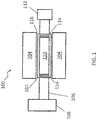
- FIG. 1 schematically illustrates a portion of an electric generator 100 that includes a rotor assembly 102 and a stator 104.
- the rotor assembly 102 is integrally formed with or operably coupled to a shaft 106 driven by a rotational input 108, which may be driven by an external drive.
- the rotational input 108 can include a gearbox (e.g., driven by an aircraft engine) and/or input shaft that drives rotation of the shaft 106.
- the rotor assembly 102 is rotatably disposed at a radially inwardly location of the stator 104.
- the stator 104 includes at least one stator winding (not depicted).
- the rotor assembly 102 includes a main field wound assembly 110 that can receive a rotor excitation current from a rotor excitation current source 112.
- the rotor excitation current source 112 may also be coupled to the shaft 106.
- the excitation current source is a dynamo that an excitation current responsive to relative motion between coils and permanent magnets (e.g., an excitation stator, not depicted) and may include a rotating rectifier (not depicted) to condition the rotor excitation current.
- at least one shim 114 can be installed between the main field wound assembly 110 and a housing 116 of the rotor assembly 102.
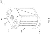
- FIG. 2 is a perspective view
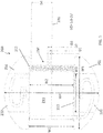
- FIG. 3 is a cross-sectional view of the main field wound assembly 110 of the rotor assembly 102 of FIG. 1 .
- the main field wound assembly 110 includes a rotor core assembly 120.
- a first end winding support 122 is coupled to a first end 124 of the rotor core assembly 120.
- a second end winding support 126 is coupled to a second end 128 of the rotor core assembly 120 axially aligned (e.g., along axis A) and opposite the first end 124 of the rotor core assembly 120.
- a coil of wire 130 is repeatedly wound about the first end winding support 122, the rotor core assembly 120, and the second end winding support 126.
- a rotor band 132 can be used to insulate the coil of wire 130 from the shaft 106 of FIG. 1 .
- One or more spring clips 134 can be used to provide a conductive path to couple the coil of wire 130 to the rotor excitation current source 112 of FIG. 1 .
- An orifice 136 along axis A can be used to allow coolant to flow between the first and second end winding supports 122, 126 to the rotor core assembly 120.
- the rotor core assembly 120 may contain amortisseur bars 138, which when connected to conductive laminations at a first end 124 and a second end 128 of the rotor core assembly 120 can be used to dampen oscillations due to speed and load fluctuations.
- the coil of wire 130 may be wound in layers such that a first layer of winding 140 is closest to the rotor core assembly 120.
- FIGS. 4-7 provide various views of an end winding support 200 which is an example of the first and second end winding supports 122, 126 of the main field wound assembly 110 of FIGS. 2 and 3 .
- the illustrated end winding support 200 such as the first and second end winding supports 122, 126, includes a pair of winding lead supports 202 formed on opposite sides of a winding slot 204 and separated by an upper slot width W1 of about 1.527 inches (3.879 cm).
- Each of the winding lead supports 202 can include a winding channel 206 routed between a lead coupling port 208 and the winding slot 204.
- the winding slot 204 includes a base support 210 and a pair of alignment members 212 that define a transition between the base support 210 and the winding lead supports 202, where a lower slot width W2 of about 1.471 inches (3.736 cm) is defined along the base support 210 between the alignment members 212.
- the base support 210 which can be part of the first and/or second end winding supports 122, 126 of FIGS. 2 and 3 may include a plurality of grooves 214 aligned along an edge 216 of the base support 210 between the winding lead supports 202.
- the grooves 214 establish a spacing constraint for the first layer of winding 140 of FIG. 3 .
- a second pair of the grooves 214 is offset from the reference line 220 by a distance D2 of about 0.084 inches (0.213 cm).
- a third pair of the grooves 214 is offset from the reference line 220 by a distance D3 of about 0.14 inches (0.356 cm).
- An Nth pair of the grooves 214 is offset from the reference line 220 by a distance D4 of about 0.7 inches (1.778 cm).
- a distance between each of the grooves 214 can be defined as distance D5 which equals distance D3 minus distance D2, or about 0.056 inches (0.142 cm).
- Each of the grooves 214 may have a radius R1 of about 0.028 inches (0.0711 cm), which substantially corresponds to a minimum radius of magnetic wire used in the coil of wire 130 of FIGS. 2 and 3 .
- Each of the winding lead supports 202 further includes a shim support groove 222 having a shim support width W3 of about 1.295 inches (3.289 cm) and a shim support depth D6 of about 0.033 inches (0.0838 cm).
- the shim support width W3 is defined orthogonal to the upper slot width W1 and the lower slot width W2.
- a total width W4 of the end winding support 200 is about 3.162 inches (8.031 cm).
- An end winding lead support width W5 is about 2.456 inches (6.238 cm).
- a number of ratios may be defined with respect to the first and second end winding supports 122, 126 of the main field wound assembly 110 of FIGS. 2 and 3 as illustrated by the example of the end winding support 200 of FIGS. 4-7 .
- a ratio of the upper slot width W1 to the lower slot width W2 is between 1.024 and 1.053.
- a ratio of a distance D5 between each of the grooves and a radius R1 of each of the grooves can be between 1.54 and 2.66.
- a ratio of the shim support width W3 to the shim support depth D6 can be between 32.94 and 48.34.
- a ratio of the upper slot width W1 to the shim support width W3 can be between 1.16 and 1.20.
- a ratio of the lower slot width W2 to the shim support width W3 can be between 1.11 and 1.16.
- a ratio of the total width W4 of the end winding support 200 to the upper slot width W1 can be between 2.05 and 2.09.
- a ratio of the total width W4 of the end winding support 200 to the lower slot width W2 can be between 2.13 and 2.17.
- a ratio of the end winding lead support width W5 to the shim support width W3 can be between 1.88 and 1.92.
- a method of installing the main field wound assembly 110 in the electric generator 100 of FIG. 1 includes inserting the main field wound assembly 110 into the rotor assembly 102 of the electric generator 100.
- the main field wound assembly 110 can include a rotor core assembly 120, a first end winding support 122 coupled to a first end 124 of the rotor core assembly 120, a second end winding support 126 coupled to a second end 128 of the rotor core assembly 120 axially aligned and opposite the first end 124 of the rotor core assembly 120, and a coil of wire 130 repeatedly wound about the first end winding support 122, the rotor core assembly 120, and the second end winding support 126.
- At least one shim 114 can be installed between the main field wound assembly 110 and a housing 116 of the rotor assembly 102.
- the method can also include connecting a rotor excitation current source 112 to the coil of wire 130 through the lead coupling ports 208 of the first or second end winding supports 122, 126.
- each of the winding lead supports 202 may further include shim support groove 222 having shim support width W3 and shim support depth D6 to install at least one shim 114.
Landscapes
- Engineering & Computer Science (AREA)
- Power Engineering (AREA)
- Manufacturing & Machinery (AREA)
- Insulation, Fastening Of Motor, Generator Windings (AREA)
- Windings For Motors And Generators (AREA)
Description
- The present invention relates to electric generators, and more particularly to winding assemblies for electric generators.
- Electric generators typically include a rotor on which is produced a magnetic field that rotates within a stationary set of conductors wound in coils on an iron core, referred to as a stator. As a mechanical input caused the rotor to turn, the magnetic field cuts across the conductors and induces a current in the stator windings. Often there are three sets of stator windings, physically offset so that the rotating magnetic field produces a three phase current, displaced by one-third of a period with respect to each other.
- The rotor's magnetic field may be produced by a coil of wire wound onto a iron core, where the coil is energized with direct current provided by an exciter element such as a dynamo. The coil includes multiple turns of copper wire and must be supported near the outer diameter of the rotor to keep the wire in place and prevent breakage. During most of the length of the rotor this support can be provided by the geometry of the steel core, but on the ends of the core where the wire crosses from one side to the other, an additional support piece must be provided. The additional support piece must be able to retain the coil at high temperatures and possibly in a lubricating oil environment. High rotational speeds and vibrations, for instance, when used on an aircraft, can place additional strain loads on the coil, risking reduced service life if the coil support does not adequately retain the coil.
- A winding assembly is taught in
US 6,483,220 . - According to one embodiment, there is provided an end winding support for an electric generator as defined by claim 1.
- [deleted]
- According to a further embodiment, there is provided a method of installing a main field wound assembly in an electric generator as defined by claim 5.
- The subject matter which is regarded as the present disclosure is particularly pointed out and distinctly claimed in the claims at the conclusion of the specification. The foregoing and other features, and advantages of the present disclosure are apparent from the following detailed description taken in conjunction with the accompanying drawings in which:
-
FIG. 1 is a schematic of a rotor assembly and a stator of a generator according to an embodiment; -
FIG. 2 is a perspective view of a main field wound assembly of the rotor assembly ofFIG. 1 ; -
FIG. 3 is a cross-sectional view of the main field wound assembly ofFIG. 2 ; -
FIG. 4 is a perspective view of an end winding support of the main field wound assembly ofFIG. 2 ; -
FIG. 5 is a top view of the end winding support ofFIG. 4 ; -
FIG. 6 is a partial view of grooves of the end winding support ofFIG. 4 ; and -
FIG. 7 is a side view of the end winding support ofFIG. 4 . -
FIG. 1 schematically illustrates a portion of anelectric generator 100 that includes arotor assembly 102 and astator 104. Therotor assembly 102 is integrally formed with or operably coupled to ashaft 106 driven by arotational input 108, which may be driven by an external drive. For example, therotational input 108 can include a gearbox (e.g., driven by an aircraft engine) and/or input shaft that drives rotation of theshaft 106. Therotor assembly 102 is rotatably disposed at a radially inwardly location of thestator 104. Thestator 104 includes at least one stator winding (not depicted). - The
rotor assembly 102 includes a mainfield wound assembly 110 that can receive a rotor excitation current from a rotor excitationcurrent source 112. The rotor excitationcurrent source 112 may also be coupled to theshaft 106. In one embodiment, the excitation current source is a dynamo that an excitation current responsive to relative motion between coils and permanent magnets (e.g., an excitation stator, not depicted) and may include a rotating rectifier (not depicted) to condition the rotor excitation current. To secure the mainfield wound assembly 110 in therotor assembly 102 during rotation, at least oneshim 114 can be installed between the mainfield wound assembly 110 and ahousing 116 of therotor assembly 102. -
FIG. 2 is a perspective view, andFIG. 3 is a cross-sectional view of the mainfield wound assembly 110 of therotor assembly 102 ofFIG. 1 . According to an embodiment, the mainfield wound assembly 110 includes arotor core assembly 120. A firstend winding support 122 is coupled to afirst end 124 of therotor core assembly 120. A secondend winding support 126 is coupled to asecond end 128 of therotor core assembly 120 axially aligned (e.g., along axis A) and opposite thefirst end 124 of therotor core assembly 120. A coil ofwire 130 is repeatedly wound about the firstend winding support 122, therotor core assembly 120, and the secondend winding support 126. Arotor band 132 can be used to insulate the coil ofwire 130 from theshaft 106 ofFIG. 1 . One ormore spring clips 134 can be used to provide a conductive path to couple the coil ofwire 130 to the rotor excitationcurrent source 112 ofFIG. 1 . Anorifice 136 along axis A can be used to allow coolant to flow between the first and second end winding supports 122, 126 to therotor core assembly 120. Therotor core assembly 120 may containamortisseur bars 138, which when connected to conductive laminations at afirst end 124 and asecond end 128 of therotor core assembly 120 can be used to dampen oscillations due to speed and load fluctuations. As can be seen inFIG. 3 , the coil ofwire 130 may be wound in layers such that a first layer of winding 140 is closest to therotor core assembly 120. -
FIGS. 4-7 provide various views of anend winding support 200 which is an example of the first and second end winding supports 122, 126 of the mainfield wound assembly 110 ofFIGS. 2 and3 . The illustratedend winding support 200, such as the first and second end winding supports 122, 126, includes a pair ofwinding lead supports 202 formed on opposite sides of awinding slot 204 and separated by an upper slot width W1 of about 1.527 inches (3.879 cm). Each of the windinglead supports 202 can include a windingchannel 206 routed between alead coupling port 208 and thewinding slot 204. Thewinding slot 204 includes abase support 210 and a pair ofalignment members 212 that define a transition between thebase support 210 and the winding lead supports 202, where a lower slot width W2 of about 1.471 inches (3.736 cm) is defined along thebase support 210 between thealignment members 212. - The
base support 210, which can be part of the first and/or second end winding supports 122, 126 ofFIGS. 2 and3 may include a plurality ofgrooves 214 aligned along anedge 216 of thebase support 210 between thewinding lead supports 202. Thegrooves 214 establish a spacing constraint for the first layer of winding 140 ofFIG. 3 . In the example ofFIG. 5 , there are about twenty-sixgrooves 214 that are centered about areference line 220, where a first pair of thegrooves 214 is offset by a distance D1 of about 0.028 inches (0.0711 cm) on either side of thereference line 220. A second pair of thegrooves 214 is offset from thereference line 220 by a distance D2 of about 0.084 inches (0.213 cm). A third pair of thegrooves 214 is offset from thereference line 220 by a distance D3 of about 0.14 inches (0.356 cm). An Nth pair of thegrooves 214 is offset from thereference line 220 by a distance D4 of about 0.7 inches (1.778 cm). A distance between each of thegrooves 214 can be defined as distance D5 which equals distance D3 minus distance D2, or about 0.056 inches (0.142 cm). Each of thegrooves 214 may have a radius R1 of about 0.028 inches (0.0711 cm), which substantially corresponds to a minimum radius of magnetic wire used in the coil ofwire 130 ofFIGS. 2 and3 . - Each of the winding lead supports 202 further includes a
shim support groove 222 having a shim support width W3 of about 1.295 inches (3.289 cm) and a shim support depth D6 of about 0.033 inches (0.0838 cm). The shim support width W3 is defined orthogonal to the upper slot width W1 and the lower slot width W2. A total width W4 of theend winding support 200 is about 3.162 inches (8.031 cm). An end winding lead support width W5 is about 2.456 inches (6.238 cm). - A number of ratios may be defined with respect to the first and second end winding supports 122, 126 of the main
field wound assembly 110 ofFIGS. 2 and3 as illustrated by the example of theend winding support 200 ofFIGS. 4-7 . In an embodiment, a ratio of the upper slot width W1 to the lower slot width W2 is between 1.024 and 1.053. A ratio of a distance D5 between each of the grooves and a radius R1 of each of the grooves can be between 1.54 and 2.66. A ratio of the shim support width W3 to the shim support depth D6 can be between 32.94 and 48.34. A ratio of the upper slot width W1 to the shim support width W3 can be between 1.16 and 1.20. A ratio of the lower slot width W2 to the shim support width W3 can be between 1.11 and 1.16. A ratio of the total width W4 of theend winding support 200 to the upper slot width W1 can be between 2.05 and 2.09. A ratio of the total width W4 of theend winding support 200 to the lower slot width W2 can be between 2.13 and 2.17. A ratio of the end winding lead support width W5 to the shim support width W3 can be between 1.88 and 1.92. - With further reference to
FIGS. 1-7 , a method of installing the main field woundassembly 110 in theelectric generator 100 ofFIG. 1 includes inserting the main field woundassembly 110 into therotor assembly 102 of theelectric generator 100. As previously described, the main field woundassembly 110 can include arotor core assembly 120, a firstend winding support 122 coupled to afirst end 124 of therotor core assembly 120, a secondend winding support 126 coupled to asecond end 128 of therotor core assembly 120 axially aligned and opposite thefirst end 124 of therotor core assembly 120, and a coil ofwire 130 repeatedly wound about the firstend winding support 122, therotor core assembly 120, and the secondend winding support 126. At least oneshim 114 can be installed between the main field woundassembly 110 and ahousing 116 of therotor assembly 102. The method can also include connecting a rotor excitationcurrent source 112 to the coil ofwire 130 through thelead coupling ports 208 of the first or secondend winding supports end winding support 200 as an embodiment of the first and/or secondend winding supports shim support groove 222 having shim support width W3 and shim support depth D6 to install at least oneshim 114. - The scope of protection is defined by the claims.
Claims (8)
- A main field wound assembly for an electric generator, the main field wound assembly comprising:a rotor core assembly (120);a first end winding support (122) coupled to a first end (124) of the rotor core assembly;a second end winding support (126) coupled to a second end (128) of the rotor core assembly axially aligned and opposite the first end of the rotor core assembly, the first and second end winding supports each comprising a pair of winding lead supports (202) formed on opposite sides of a winding slot (204) and separated by an upper slot width, each of the winding lead supports comprising a winding channel routed between a lead coupling port and the winding slot, the winding slot comprising a base support (210) and a pair of alignment members (212) that define a transition between the base support and the winding lead supports, wherein a lower slot width is defined along the base support between the alignment members and a ratio of the upper slot width to the lower slot width is between 1.024 and 1.053; anda coil of wire (130) repeatedly wound about the first end winding support, the rotor core assembly, and the second end winding support; characterized in thatthe base support (210) of each of the first and second end winding supports further comprises a plurality of grooves (214) aligned along an edge of the base support between the winding lead supports, the grooves establishing a spacing constraint for a first layer of winding the coil of wire; andwherein each of the winding lead supports (202) further comprises a shim support groove (222) having a shim support width and a shim support depth, and a ratio of the shim support width to the shim support depth is between 32.94 and 48.34; andwherein the shim support width is defined orthogonal to the upper slot width and the lower slot width on each of the first and second end winding supports.
- The main field wound assembly of claim 1, wherein a ratio of a distance between each of the grooves and a radius of each of the grooves is between 1.54 and 2.66 on each of the first and second end winding supports.
- The main field wound assembly of claim 1, wherein a ratio of an end winding lead support width to the shim support width is between 1.88 and 1.92.
- The main field wound assembly of any preceding claim, wherein a ratio of a total width of the first end winding support to the upper slot width is between 2.05 and 2.09, and a ratio of the total width of the first end winding support to the lower slot width is between 2.13 and 2.17.
- A method of installing a main field wound assembly in an electric generator, the method comprising:providing a rotor assembly (102) comprising a housing;inserting the main field wound assembly into the rotor assembly of the electric generator, the main field wound assembly comprising:a rotor core assembly (120);a first end winding support (122) coupled to a first end (124) of the rotor core assembly;a second end winding support (126) coupled to a second end (128) of the rotor core assembly axially aligned and opposite the first end of the rotor core assembly, the first and second end winding supports each comprising a pair of winding lead supports (202) formed on opposite sides of a winding slot (204) and separated by an upper slot width, each of the winding lead supports comprising a winding channel routed between a lead coupling port and the winding slot, the winding slot comprising a base support (210) and a pair of alignment members (212) that define a transition between the base support and the winding lead supports, wherein a lower slot width is defined along the base support between the alignment members and a ratio of the upper slot width to the lower slot width is between 1.024 and 1.053; anda coil of wire (130) repeatedly wound about the first end winding support, the rotor core assembly, and the second end winding support; andinstalling at least one shim (114) between the main field wound assembly and the housing of the rotor assembly; and characterized in thatthe base support of each of the first and second end winding supports further comprises a plurality of grooves (214) aligned along an edge of the base support between the winding lead supports, the grooves establishing a spacing constraint for a first layer of winding the coil of wire; andwherein each of the winding lead supports further comprises a shim support groove (222) having a shim support width and a shim support depth, and a ratio of the shim support width to the shim support depth is between 32.94 and 48.34; andwherein the shim support width is defined orthogonal to the upper slot width and the lower slot width on each of the first and second end winding supports.
- The method of claim 5, further comprising:
connecting a rotor excitation current source to the coil of wire through the lead coupling ports of the first or second end winding supports, and a ratio of a distance between each of the grooves and a radius of each of the grooves is between 1.54 and 2.66 on each of the first and second end winding supports. - The method of claim 5, wherein a ratio of an end winding lead support width to the shim support width is between 1.88 and 1.92.
- The method of any of claims 5 to 7, wherein a ratio of a total width the first end winding support to the upper slot width is between 2.05 and 2.09, and a ratio of the total width of the first end winding support to the lower slot width is between 2.13 and 2.17.
Applications Claiming Priority (1)
| Application Number | Priority Date | Filing Date | Title |
|---|---|---|---|
| US14/748,857 US9893584B2 (en) | 2015-06-24 | 2015-06-24 | End winding support for an electric generator |
Publications (3)
| Publication Number | Publication Date |
|---|---|
| EP3109975A2 EP3109975A2 (en) | 2016-12-28 |
| EP3109975A3 EP3109975A3 (en) | 2017-01-11 |
| EP3109975B1 true EP3109975B1 (en) | 2019-10-23 |
Family
ID=56203233
Family Applications (1)
| Application Number | Title | Priority Date | Filing Date |
|---|---|---|---|
| EP16175945.1A Active EP3109975B1 (en) | 2015-06-24 | 2016-06-23 | End winding support for an electric generator |
Country Status (2)
| Country | Link |
|---|---|
| US (1) | US9893584B2 (en) |
| EP (1) | EP3109975B1 (en) |
Families Citing this family (2)
| Publication number | Priority date | Publication date | Assignee | Title |
|---|---|---|---|---|
| US9893584B2 (en) * | 2015-06-24 | 2018-02-13 | Hamilton Sundstrand Corporation | End winding support for an electric generator |
| US11876423B2 (en) * | 2021-11-04 | 2024-01-16 | Hamilton Sundstrand Corporation | Two-piece end turn winding support |
Family Cites Families (28)
| Publication number | Priority date | Publication date | Assignee | Title |
|---|---|---|---|---|
| DE1922153A1 (en) * | 1969-04-25 | 1970-10-29 | Siemens Ag | Runner of a four-pole electrical synchronous machine with pronounced poles |
| US4562641A (en) * | 1983-08-17 | 1986-01-07 | Sundstrand Corporation | Method of assembling a magnetic rotor |
| US4583696A (en) * | 1984-01-05 | 1986-04-22 | Sundstrand Corporation | Method of precision winding a rotor |
| US4603274A (en) * | 1984-01-05 | 1986-07-29 | Sundstrand Corporation | Precision wound rotor and method of winding |
| US4486676A (en) * | 1984-01-16 | 1984-12-04 | Electric Power Research Institute, Inc. | Superconducting rotor with end turn region intermittent support and cooling assembly |
| US5144182A (en) * | 1991-09-04 | 1992-09-01 | Onan Corporation | Skewed rotor assembly |
| US5177390A (en) * | 1991-09-17 | 1993-01-05 | Kohler Co. | Rotor |
| US5298823A (en) * | 1992-09-04 | 1994-03-29 | Sundstrand Corporation | Main field winding and connections for a dynamoelectric machine |
| GB9304871D0 (en) * | 1993-03-10 | 1993-04-28 | Lucas Ind Plc | A winding connector for a rotary electrical component |
| US6483220B1 (en) * | 1995-06-22 | 2002-11-19 | Hamilton Sundstrand Corporation | Precision-wound rotor for a dynamoelectric machine |
| US5831367A (en) * | 1997-02-13 | 1998-11-03 | Emerson Electric Co. | Line-start reluctance motor with grain-oriented rotor laminations |
| EP1107430A3 (en) * | 1999-12-06 | 2003-10-29 | General Electric Company | Expandable flat winding for electric machine rotating fields |
| US6590311B1 (en) * | 1999-12-06 | 2003-07-08 | General Electric Company | Cross-shaped rotor shaft for electrical machine |
| US6437476B1 (en) * | 1999-12-06 | 2002-08-20 | General Electric Company | Multi-pole electric machine including flat winding for generator fields |
| US6710497B2 (en) * | 2001-10-16 | 2004-03-23 | General Electric Company | Apparatus and method for a field winding assembly mountable on a rotor in a synchronous machine |
| JP4350972B2 (en) * | 2003-05-08 | 2009-10-28 | ヤマハモーターエレクトロニクス株式会社 | Rotating machine armature |
| JP4535147B2 (en) * | 2008-02-29 | 2010-09-01 | 株式会社デンソー | Rotating electric machine stator and rotating electric machine |
| US8269393B2 (en) | 2009-06-18 | 2012-09-18 | Hamilton Sundstrand Corporation | Crowned end winding support for main wound field of a generator |
| FR2984034B1 (en) * | 2011-12-08 | 2014-08-22 | Renault Sa | DEVICE FOR GUIDING A SET OF ELECTRIC WIRES FOR AN ELECTRIC MOTOR ROTOR |
| US20140028141A1 (en) * | 2012-07-27 | 2014-01-30 | Illinois Tool Works Inc. | Rotor and generator for reducing harmonics |
| GB2493658B (en) * | 2012-10-15 | 2015-05-20 | Protean Electric Ltd | A tooth for an electric motor or generator |
| DE102012223977A1 (en) * | 2012-12-20 | 2014-06-26 | Hilti Aktiengesellschaft | Rotor package with function carrier |
| US9837868B2 (en) * | 2014-02-28 | 2017-12-05 | Ge Aviation Systems Llc | Rotor assembly for an electric machine |
| US20160211713A1 (en) * | 2015-01-16 | 2016-07-21 | Hamilton Sundstrand Corporation | One-piece end winding support with integrated lubricant manifold |
| US9653958B2 (en) * | 2015-01-16 | 2017-05-16 | Hamilton Sundstrand Corporation | Rotor wedge with arms |
| US10333365B2 (en) * | 2015-01-16 | 2019-06-25 | Hamilton Sundstrand Corporation | End winding support segment with integrated lubricant manifold |
| US9819239B2 (en) * | 2015-05-07 | 2017-11-14 | Hamilton Sundstrand Corporation | End winding support and heat sink for liquid-cooled generator |
| US9893584B2 (en) * | 2015-06-24 | 2018-02-13 | Hamilton Sundstrand Corporation | End winding support for an electric generator |
-
2015
- 2015-06-24 US US14/748,857 patent/US9893584B2/en active Active
-
2016
- 2016-06-23 EP EP16175945.1A patent/EP3109975B1/en active Active
Non-Patent Citations (1)
| Title |
|---|
| None * |
Also Published As
| Publication number | Publication date |
|---|---|
| EP3109975A3 (en) | 2017-01-11 |
| US9893584B2 (en) | 2018-02-13 |
| US20160380501A1 (en) | 2016-12-29 |
| EP3109975A2 (en) | 2016-12-28 |
Similar Documents
| Publication | Publication Date | Title |
|---|---|---|
| US6683397B2 (en) | Electric machine having at least one magnetic field detector | |
| US9680341B2 (en) | Rotating electric machine including rotor core with slots having protrusions | |
| EP2961042B1 (en) | Permanent magnet machine | |
| US6891299B2 (en) | Rotary electric machine having a flux-concentrating rotor and a stator with windings on teeth | |
| US8232702B2 (en) | Apparatus for a high speed sleeveless rotor | |
| EP2329583B1 (en) | Winding insulation arrangement for axial flux machines | |
| CN101267130B (en) | Armature overlapping slice | |
| US7342331B2 (en) | Multi-plane flexible rotor balancing | |
| CN209389792U (en) | Brushless motor and its C-shaped stator core | |
| CN110663158B (en) | Dual magnetic phase material ring for AC motor | |
| EP3086444B1 (en) | Rotating electric machine | |
| EP3404802B1 (en) | Generator with enhanced stator cooling and reduced windage loss | |
| EP3193432A1 (en) | Stator and electric motor | |
| US7015617B2 (en) | High speed generator with rotor coil support assemblies secured to interlamination disks | |
| US9893584B2 (en) | End winding support for an electric generator | |
| EP2615730B1 (en) | Brushless starter-generator assembly and method to control magnetic flux excitation | |
| EP3065267B1 (en) | Cores for electrical machines | |
| US20130221798A1 (en) | Alternator ratios | |
| JP7085845B2 (en) | Rotating machine stator and rotating machine | |
| EP1679427B1 (en) | Turbogenerator | |
| US6879083B2 (en) | Generator rotor coil end-turn retention system and method | |
| EP2066007A2 (en) | Rotary electric machine | |
| US12573909B2 (en) | Electrical machine having a lead retention assembly | |
| WO2016084219A1 (en) | Permanent magnet type rotating electrical machine, and drive system and compressor system using same | |
| KR20140087365A (en) | Stator bobbin for motor |
Legal Events
| Date | Code | Title | Description |
|---|---|---|---|
| PUAI | Public reference made under article 153(3) epc to a published international application that has entered the european phase |
Free format text: ORIGINAL CODE: 0009012 |
|
| STAA | Information on the status of an ep patent application or granted ep patent |
Free format text: STATUS: THE APPLICATION HAS BEEN PUBLISHED |
|
| PUAL | Search report despatched |
Free format text: ORIGINAL CODE: 0009013 |
|
| AK | Designated contracting states |
Kind code of ref document: A2 Designated state(s): AL AT BE BG CH CY CZ DE DK EE ES FI FR GB GR HR HU IE IS IT LI LT LU LV MC MK MT NL NO PL PT RO RS SE SI SK SM TR |
|
| AX | Request for extension of the european patent |
Extension state: BA ME |
|
| AK | Designated contracting states |
Kind code of ref document: A3 Designated state(s): AL AT BE BG CH CY CZ DE DK EE ES FI FR GB GR HR HU IE IS IT LI LT LU LV MC MK MT NL NO PL PT RO RS SE SI SK SM TR |
|
| AX | Request for extension of the european patent |
Extension state: BA ME |
|
| RIC1 | Information provided on ipc code assigned before grant |
Ipc: H02K 1/24 20060101ALN20161206BHEP Ipc: H02K 3/52 20060101AFI20161206BHEP |
|
| STAA | Information on the status of an ep patent application or granted ep patent |
Free format text: STATUS: REQUEST FOR EXAMINATION WAS MADE |
|
| 17P | Request for examination filed |
Effective date: 20170710 |
|
| RBV | Designated contracting states (corrected) |
Designated state(s): AL AT BE BG CH CY CZ DE DK EE ES FI FR GB GR HR HU IE IS IT LI LT LU LV MC MK MT NL NO PL PT RO RS SE SI SK SM TR |
|
| REG | Reference to a national code |
Ref country code: DE Ref legal event code: R079 Ref document number: 602016022792 Country of ref document: DE Free format text: PREVIOUS MAIN CLASS: H02K0003510000 Ipc: H02K0003520000 |
|
| RIC1 | Information provided on ipc code assigned before grant |
Ipc: H02K 3/52 20060101AFI20190403BHEP Ipc: H02K 1/24 20060101ALN20190403BHEP |
|
| GRAP | Despatch of communication of intention to grant a patent |
Free format text: ORIGINAL CODE: EPIDOSNIGR1 |
|
| STAA | Information on the status of an ep patent application or granted ep patent |
Free format text: STATUS: GRANT OF PATENT IS INTENDED |
|
| RIC1 | Information provided on ipc code assigned before grant |
Ipc: H02K 3/52 20060101AFI20190502BHEP Ipc: H02K 1/24 20060101ALN20190502BHEP |
|
| INTG | Intention to grant announced |
Effective date: 20190514 |
|
| GRAS | Grant fee paid |
Free format text: ORIGINAL CODE: EPIDOSNIGR3 |
|
| GRAA | (expected) grant |
Free format text: ORIGINAL CODE: 0009210 |
|
| STAA | Information on the status of an ep patent application or granted ep patent |
Free format text: STATUS: THE PATENT HAS BEEN GRANTED |
|
| AK | Designated contracting states |
Kind code of ref document: B1 Designated state(s): AL AT BE BG CH CY CZ DE DK EE ES FI FR GB GR HR HU IE IS IT LI LT LU LV MC MK MT NL NO PL PT RO RS SE SI SK SM TR |
|
| REG | Reference to a national code |
Ref country code: GB Ref legal event code: FG4D |
|
| REG | Reference to a national code |
Ref country code: CH Ref legal event code: EP |
|
| REG | Reference to a national code |
Ref country code: IE Ref legal event code: FG4D |
|
| REG | Reference to a national code |
Ref country code: AT Ref legal event code: REF Ref document number: 1194784 Country of ref document: AT Kind code of ref document: T Effective date: 20191115 |
|
| REG | Reference to a national code |
Ref country code: DE Ref legal event code: R096 Ref document number: 602016022792 Country of ref document: DE |
|
| REG | Reference to a national code |
Ref country code: NL Ref legal event code: MP Effective date: 20191023 |
|
| REG | Reference to a national code |
Ref country code: LT Ref legal event code: MG4D |
|
| PG25 | Lapsed in a contracting state [announced via postgrant information from national office to epo] |
Ref country code: LT Free format text: LAPSE BECAUSE OF FAILURE TO SUBMIT A TRANSLATION OF THE DESCRIPTION OR TO PAY THE FEE WITHIN THE PRESCRIBED TIME-LIMIT Effective date: 20191023 Ref country code: NL Free format text: LAPSE BECAUSE OF FAILURE TO SUBMIT A TRANSLATION OF THE DESCRIPTION OR TO PAY THE FEE WITHIN THE PRESCRIBED TIME-LIMIT Effective date: 20191023 Ref country code: FI Free format text: LAPSE BECAUSE OF FAILURE TO SUBMIT A TRANSLATION OF THE DESCRIPTION OR TO PAY THE FEE WITHIN THE PRESCRIBED TIME-LIMIT Effective date: 20191023 Ref country code: BG Free format text: LAPSE BECAUSE OF FAILURE TO SUBMIT A TRANSLATION OF THE DESCRIPTION OR TO PAY THE FEE WITHIN THE PRESCRIBED TIME-LIMIT Effective date: 20200123 Ref country code: GR Free format text: LAPSE BECAUSE OF FAILURE TO SUBMIT A TRANSLATION OF THE DESCRIPTION OR TO PAY THE FEE WITHIN THE PRESCRIBED TIME-LIMIT Effective date: 20200124 Ref country code: NO Free format text: LAPSE BECAUSE OF FAILURE TO SUBMIT A TRANSLATION OF THE DESCRIPTION OR TO PAY THE FEE WITHIN THE PRESCRIBED TIME-LIMIT Effective date: 20200123 Ref country code: PL Free format text: LAPSE BECAUSE OF FAILURE TO SUBMIT A TRANSLATION OF THE DESCRIPTION OR TO PAY THE FEE WITHIN THE PRESCRIBED TIME-LIMIT Effective date: 20191023 Ref country code: LV Free format text: LAPSE BECAUSE OF FAILURE TO SUBMIT A TRANSLATION OF THE DESCRIPTION OR TO PAY THE FEE WITHIN THE PRESCRIBED TIME-LIMIT Effective date: 20191023 Ref country code: PT Free format text: LAPSE BECAUSE OF FAILURE TO SUBMIT A TRANSLATION OF THE DESCRIPTION OR TO PAY THE FEE WITHIN THE PRESCRIBED TIME-LIMIT Effective date: 20200224 Ref country code: SE Free format text: LAPSE BECAUSE OF FAILURE TO SUBMIT A TRANSLATION OF THE DESCRIPTION OR TO PAY THE FEE WITHIN THE PRESCRIBED TIME-LIMIT Effective date: 20191023 |
|
| PG25 | Lapsed in a contracting state [announced via postgrant information from national office to epo] |
Ref country code: HR Free format text: LAPSE BECAUSE OF FAILURE TO SUBMIT A TRANSLATION OF THE DESCRIPTION OR TO PAY THE FEE WITHIN THE PRESCRIBED TIME-LIMIT Effective date: 20191023 Ref country code: IS Free format text: LAPSE BECAUSE OF FAILURE TO SUBMIT A TRANSLATION OF THE DESCRIPTION OR TO PAY THE FEE WITHIN THE PRESCRIBED TIME-LIMIT Effective date: 20200224 Ref country code: RS Free format text: LAPSE BECAUSE OF FAILURE TO SUBMIT A TRANSLATION OF THE DESCRIPTION OR TO PAY THE FEE WITHIN THE PRESCRIBED TIME-LIMIT Effective date: 20191023 |
|
| PG25 | Lapsed in a contracting state [announced via postgrant information from national office to epo] |
Ref country code: AL Free format text: LAPSE BECAUSE OF FAILURE TO SUBMIT A TRANSLATION OF THE DESCRIPTION OR TO PAY THE FEE WITHIN THE PRESCRIBED TIME-LIMIT Effective date: 20191023 |
|
| REG | Reference to a national code |
Ref country code: DE Ref legal event code: R097 Ref document number: 602016022792 Country of ref document: DE |
|
| PG2D | Information on lapse in contracting state deleted |
Ref country code: IS |
|
| PG25 | Lapsed in a contracting state [announced via postgrant information from national office to epo] |
Ref country code: RO Free format text: LAPSE BECAUSE OF FAILURE TO SUBMIT A TRANSLATION OF THE DESCRIPTION OR TO PAY THE FEE WITHIN THE PRESCRIBED TIME-LIMIT Effective date: 20191023 Ref country code: DK Free format text: LAPSE BECAUSE OF FAILURE TO SUBMIT A TRANSLATION OF THE DESCRIPTION OR TO PAY THE FEE WITHIN THE PRESCRIBED TIME-LIMIT Effective date: 20191023 Ref country code: ES Free format text: LAPSE BECAUSE OF FAILURE TO SUBMIT A TRANSLATION OF THE DESCRIPTION OR TO PAY THE FEE WITHIN THE PRESCRIBED TIME-LIMIT Effective date: 20191023 Ref country code: EE Free format text: LAPSE BECAUSE OF FAILURE TO SUBMIT A TRANSLATION OF THE DESCRIPTION OR TO PAY THE FEE WITHIN THE PRESCRIBED TIME-LIMIT Effective date: 20191023 Ref country code: CZ Free format text: LAPSE BECAUSE OF FAILURE TO SUBMIT A TRANSLATION OF THE DESCRIPTION OR TO PAY THE FEE WITHIN THE PRESCRIBED TIME-LIMIT Effective date: 20191023 Ref country code: IS Free format text: LAPSE BECAUSE OF FAILURE TO SUBMIT A TRANSLATION OF THE DESCRIPTION OR TO PAY THE FEE WITHIN THE PRESCRIBED TIME-LIMIT Effective date: 20200223 |
|
| REG | Reference to a national code |
Ref country code: AT Ref legal event code: MK05 Ref document number: 1194784 Country of ref document: AT Kind code of ref document: T Effective date: 20191023 |
|
| PLBE | No opposition filed within time limit |
Free format text: ORIGINAL CODE: 0009261 |
|
| STAA | Information on the status of an ep patent application or granted ep patent |
Free format text: STATUS: NO OPPOSITION FILED WITHIN TIME LIMIT |
|
| PG25 | Lapsed in a contracting state [announced via postgrant information from national office to epo] |
Ref country code: SM Free format text: LAPSE BECAUSE OF FAILURE TO SUBMIT A TRANSLATION OF THE DESCRIPTION OR TO PAY THE FEE WITHIN THE PRESCRIBED TIME-LIMIT Effective date: 20191023 Ref country code: IT Free format text: LAPSE BECAUSE OF FAILURE TO SUBMIT A TRANSLATION OF THE DESCRIPTION OR TO PAY THE FEE WITHIN THE PRESCRIBED TIME-LIMIT Effective date: 20191023 Ref country code: SK Free format text: LAPSE BECAUSE OF FAILURE TO SUBMIT A TRANSLATION OF THE DESCRIPTION OR TO PAY THE FEE WITHIN THE PRESCRIBED TIME-LIMIT Effective date: 20191023 |
|
| 26N | No opposition filed |
Effective date: 20200724 |
|
| PG25 | Lapsed in a contracting state [announced via postgrant information from national office to epo] |
Ref country code: SI Free format text: LAPSE BECAUSE OF FAILURE TO SUBMIT A TRANSLATION OF THE DESCRIPTION OR TO PAY THE FEE WITHIN THE PRESCRIBED TIME-LIMIT Effective date: 20191023 Ref country code: AT Free format text: LAPSE BECAUSE OF FAILURE TO SUBMIT A TRANSLATION OF THE DESCRIPTION OR TO PAY THE FEE WITHIN THE PRESCRIBED TIME-LIMIT Effective date: 20191023 |
|
| REG | Reference to a national code |
Ref country code: DE Ref legal event code: R119 Ref document number: 602016022792 Country of ref document: DE |
|
| PG25 | Lapsed in a contracting state [announced via postgrant information from national office to epo] |
Ref country code: MC Free format text: LAPSE BECAUSE OF FAILURE TO SUBMIT A TRANSLATION OF THE DESCRIPTION OR TO PAY THE FEE WITHIN THE PRESCRIBED TIME-LIMIT Effective date: 20191023 |
|
| REG | Reference to a national code |
Ref country code: CH Ref legal event code: PL |
|
| PG25 | Lapsed in a contracting state [announced via postgrant information from national office to epo] |
Ref country code: LU Free format text: LAPSE BECAUSE OF NON-PAYMENT OF DUE FEES Effective date: 20200623 |
|
| REG | Reference to a national code |
Ref country code: BE Ref legal event code: MM Effective date: 20200630 |
|
| PG25 | Lapsed in a contracting state [announced via postgrant information from national office to epo] |
Ref country code: IE Free format text: LAPSE BECAUSE OF NON-PAYMENT OF DUE FEES Effective date: 20200623 Ref country code: CH Free format text: LAPSE BECAUSE OF NON-PAYMENT OF DUE FEES Effective date: 20200630 Ref country code: LI Free format text: LAPSE BECAUSE OF NON-PAYMENT OF DUE FEES Effective date: 20200630 |
|
| PG25 | Lapsed in a contracting state [announced via postgrant information from national office to epo] |
Ref country code: BE Free format text: LAPSE BECAUSE OF NON-PAYMENT OF DUE FEES Effective date: 20200630 Ref country code: DE Free format text: LAPSE BECAUSE OF NON-PAYMENT OF DUE FEES Effective date: 20210101 |
|
| PG25 | Lapsed in a contracting state [announced via postgrant information from national office to epo] |
Ref country code: TR Free format text: LAPSE BECAUSE OF FAILURE TO SUBMIT A TRANSLATION OF THE DESCRIPTION OR TO PAY THE FEE WITHIN THE PRESCRIBED TIME-LIMIT Effective date: 20191023 Ref country code: MT Free format text: LAPSE BECAUSE OF FAILURE TO SUBMIT A TRANSLATION OF THE DESCRIPTION OR TO PAY THE FEE WITHIN THE PRESCRIBED TIME-LIMIT Effective date: 20191023 Ref country code: CY Free format text: LAPSE BECAUSE OF FAILURE TO SUBMIT A TRANSLATION OF THE DESCRIPTION OR TO PAY THE FEE WITHIN THE PRESCRIBED TIME-LIMIT Effective date: 20191023 |
|
| PG25 | Lapsed in a contracting state [announced via postgrant information from national office to epo] |
Ref country code: MK Free format text: LAPSE BECAUSE OF FAILURE TO SUBMIT A TRANSLATION OF THE DESCRIPTION OR TO PAY THE FEE WITHIN THE PRESCRIBED TIME-LIMIT Effective date: 20191023 |
|
| P01 | Opt-out of the competence of the unified patent court (upc) registered |
Effective date: 20230522 |
|
| PGFP | Annual fee paid to national office [announced via postgrant information from national office to epo] |
Ref country code: GB Payment date: 20250520 Year of fee payment: 10 |
|
| PGFP | Annual fee paid to national office [announced via postgrant information from national office to epo] |
Ref country code: FR Payment date: 20250521 Year of fee payment: 10 |