EP3109930A1 - Fuel cell system and control method for fuel cell system - Google Patents
Fuel cell system and control method for fuel cell system Download PDFInfo
- Publication number
- EP3109930A1 EP3109930A1 EP14882528.4A EP14882528A EP3109930A1 EP 3109930 A1 EP3109930 A1 EP 3109930A1 EP 14882528 A EP14882528 A EP 14882528A EP 3109930 A1 EP3109930 A1 EP 3109930A1
- Authority
- EP
- European Patent Office
- Prior art keywords
- fuel cell
- estimation
- current
- output current
- value
- Prior art date
- Legal status (The legal status is an assumption and is not a legal conclusion. Google has not performed a legal analysis and makes no representation as to the accuracy of the status listed.)
- Granted
Links
- 239000000446 fuel Substances 0.000 title claims abstract description 305
- 238000000034 method Methods 0.000 title claims description 101
- 230000008859 change Effects 0.000 claims abstract description 13
- 238000010248 power generation Methods 0.000 claims description 26
- 230000007423 decrease Effects 0.000 claims description 16
- 239000007789 gas Substances 0.000 description 114
- 230000008569 process Effects 0.000 description 91
- 238000012545 processing Methods 0.000 description 48
- 239000000498 cooling water Substances 0.000 description 30
- 230000002265 prevention Effects 0.000 description 19
- 238000004364 calculation method Methods 0.000 description 15
- XLYOFNOQVPJJNP-UHFFFAOYSA-N water Substances O XLYOFNOQVPJJNP-UHFFFAOYSA-N 0.000 description 14
- 230000009467 reduction Effects 0.000 description 13
- 230000006866 deterioration Effects 0.000 description 12
- 239000012528 membrane Substances 0.000 description 11
- 239000003792 electrolyte Substances 0.000 description 10
- 238000010926 purge Methods 0.000 description 10
- 238000007599 discharging Methods 0.000 description 8
- 230000001105 regulatory effect Effects 0.000 description 8
- QVGXLLKOCUKJST-UHFFFAOYSA-N atomic oxygen Chemical compound [O] QVGXLLKOCUKJST-UHFFFAOYSA-N 0.000 description 7
- 239000003054 catalyst Substances 0.000 description 7
- 238000009792 diffusion process Methods 0.000 description 7
- 239000001301 oxygen Substances 0.000 description 7
- 229910052760 oxygen Inorganic materials 0.000 description 7
- 238000001816 cooling Methods 0.000 description 5
- 238000003411 electrode reaction Methods 0.000 description 5
- 238000002474 experimental method Methods 0.000 description 5
- 238000012886 linear function Methods 0.000 description 5
- UFHFLCQGNIYNRP-UHFFFAOYSA-N Hydrogen Chemical compound [H][H] UFHFLCQGNIYNRP-UHFFFAOYSA-N 0.000 description 4
- 230000006870 function Effects 0.000 description 4
- 239000001257 hydrogen Substances 0.000 description 4
- 229910052739 hydrogen Inorganic materials 0.000 description 4
- BASFCYQUMIYNBI-UHFFFAOYSA-N platinum Chemical compound [Pt] BASFCYQUMIYNBI-UHFFFAOYSA-N 0.000 description 4
- 238000001514 detection method Methods 0.000 description 3
- 238000010586 diagram Methods 0.000 description 3
- 239000000203 mixture Substances 0.000 description 3
- 238000011084 recovery Methods 0.000 description 3
- IJGRMHOSHXDMSA-UHFFFAOYSA-N Atomic nitrogen Chemical compound N#N IJGRMHOSHXDMSA-UHFFFAOYSA-N 0.000 description 2
- 230000000875 corresponding effect Effects 0.000 description 2
- 230000003247 decreasing effect Effects 0.000 description 2
- 239000007800 oxidant agent Substances 0.000 description 2
- 230000001590 oxidative effect Effects 0.000 description 2
- 229910052697 platinum Inorganic materials 0.000 description 2
- 230000001172 regenerating effect Effects 0.000 description 2
- 239000004065 semiconductor Substances 0.000 description 2
- OKTJSMMVPCPJKN-UHFFFAOYSA-N Carbon Chemical compound [C] OKTJSMMVPCPJKN-UHFFFAOYSA-N 0.000 description 1
- 229920000049 Carbon (fiber) Polymers 0.000 description 1
- 230000004913 activation Effects 0.000 description 1
- 230000008901 benefit Effects 0.000 description 1
- 230000002457 bidirectional effect Effects 0.000 description 1
- 229910052799 carbon Inorganic materials 0.000 description 1
- 239000006229 carbon black Substances 0.000 description 1
- 239000004917 carbon fiber Substances 0.000 description 1
- 239000002131 composite material Substances 0.000 description 1
- 230000001276 controlling effect Effects 0.000 description 1
- 230000002596 correlated effect Effects 0.000 description 1
- 230000000994 depressogenic effect Effects 0.000 description 1
- 239000004744 fabric Substances 0.000 description 1
- 239000002737 fuel gas Substances 0.000 description 1
- XLYOFNOQVPJJNP-ZSJDYOACSA-N heavy water Substances [2H]O[2H] XLYOFNOQVPJJNP-ZSJDYOACSA-N 0.000 description 1
- 239000011261 inert gas Substances 0.000 description 1
- 239000003014 ion exchange membrane Substances 0.000 description 1
- 238000010030 laminating Methods 0.000 description 1
- VNWKTOKETHGBQD-UHFFFAOYSA-N methane Chemical compound C VNWKTOKETHGBQD-UHFFFAOYSA-N 0.000 description 1
- 229910052757 nitrogen Inorganic materials 0.000 description 1
- 230000036284 oxygen consumption Effects 0.000 description 1
- 239000002245 particle Substances 0.000 description 1
- 230000010287 polarization Effects 0.000 description 1
- 230000004044 response Effects 0.000 description 1
- 239000000126 substance Substances 0.000 description 1
- 230000001360 synchronised effect Effects 0.000 description 1
- 238000011144 upstream manufacturing Methods 0.000 description 1
Images


Classifications
-
- H—ELECTRICITY
- H01—ELECTRIC ELEMENTS
- H01M—PROCESSES OR MEANS, e.g. BATTERIES, FOR THE DIRECT CONVERSION OF CHEMICAL ENERGY INTO ELECTRICAL ENERGY
- H01M8/00—Fuel cells; Manufacture thereof
- H01M8/04—Auxiliary arrangements, e.g. for control of pressure or for circulation of fluids
- H01M8/04298—Processes for controlling fuel cells or fuel cell systems
- H01M8/04694—Processes for controlling fuel cells or fuel cell systems characterised by variables to be controlled
- H01M8/04858—Electric variables
- H01M8/04925—Power, energy, capacity or load
-
- B—PERFORMING OPERATIONS; TRANSPORTING
- B60—VEHICLES IN GENERAL
- B60L—PROPULSION OF ELECTRICALLY-PROPELLED VEHICLES; SUPPLYING ELECTRIC POWER FOR AUXILIARY EQUIPMENT OF ELECTRICALLY-PROPELLED VEHICLES; ELECTRODYNAMIC BRAKE SYSTEMS FOR VEHICLES IN GENERAL; MAGNETIC SUSPENSION OR LEVITATION FOR VEHICLES; MONITORING OPERATING VARIABLES OF ELECTRICALLY-PROPELLED VEHICLES; ELECTRIC SAFETY DEVICES FOR ELECTRICALLY-PROPELLED VEHICLES
- B60L58/00—Methods or circuit arrangements for monitoring or controlling batteries or fuel cells, specially adapted for electric vehicles
- B60L58/30—Methods or circuit arrangements for monitoring or controlling batteries or fuel cells, specially adapted for electric vehicles for monitoring or controlling fuel cells
- B60L58/31—Methods or circuit arrangements for monitoring or controlling batteries or fuel cells, specially adapted for electric vehicles for monitoring or controlling fuel cells for starting of fuel cells
-
- B—PERFORMING OPERATIONS; TRANSPORTING
- B60—VEHICLES IN GENERAL
- B60L—PROPULSION OF ELECTRICALLY-PROPELLED VEHICLES; SUPPLYING ELECTRIC POWER FOR AUXILIARY EQUIPMENT OF ELECTRICALLY-PROPELLED VEHICLES; ELECTRODYNAMIC BRAKE SYSTEMS FOR VEHICLES IN GENERAL; MAGNETIC SUSPENSION OR LEVITATION FOR VEHICLES; MONITORING OPERATING VARIABLES OF ELECTRICALLY-PROPELLED VEHICLES; ELECTRIC SAFETY DEVICES FOR ELECTRICALLY-PROPELLED VEHICLES
- B60L58/00—Methods or circuit arrangements for monitoring or controlling batteries or fuel cells, specially adapted for electric vehicles
- B60L58/30—Methods or circuit arrangements for monitoring or controlling batteries or fuel cells, specially adapted for electric vehicles for monitoring or controlling fuel cells
- B60L58/32—Methods or circuit arrangements for monitoring or controlling batteries or fuel cells, specially adapted for electric vehicles for monitoring or controlling fuel cells for controlling the temperature of fuel cells, e.g. by controlling the electric load
- B60L58/34—Methods or circuit arrangements for monitoring or controlling batteries or fuel cells, specially adapted for electric vehicles for monitoring or controlling fuel cells for controlling the temperature of fuel cells, e.g. by controlling the electric load by heating
-
- H—ELECTRICITY
- H01—ELECTRIC ELEMENTS
- H01M—PROCESSES OR MEANS, e.g. BATTERIES, FOR THE DIRECT CONVERSION OF CHEMICAL ENERGY INTO ELECTRICAL ENERGY
- H01M8/00—Fuel cells; Manufacture thereof
- H01M8/04—Auxiliary arrangements, e.g. for control of pressure or for circulation of fluids
- H01M8/04223—Auxiliary arrangements, e.g. for control of pressure or for circulation of fluids during start-up or shut-down; Depolarisation or activation, e.g. purging; Means for short-circuiting defective fuel cells
- H01M8/04268—Heating of fuel cells during the start-up of the fuel cells
-
- H—ELECTRICITY
- H01—ELECTRIC ELEMENTS
- H01M—PROCESSES OR MEANS, e.g. BATTERIES, FOR THE DIRECT CONVERSION OF CHEMICAL ENERGY INTO ELECTRICAL ENERGY
- H01M8/00—Fuel cells; Manufacture thereof
- H01M8/04—Auxiliary arrangements, e.g. for control of pressure or for circulation of fluids
- H01M8/04298—Processes for controlling fuel cells or fuel cell systems
- H01M8/04313—Processes for controlling fuel cells or fuel cell systems characterised by the detection or assessment of variables; characterised by the detection or assessment of failure or abnormal function
- H01M8/04537—Electric variables
- H01M8/04544—Voltage
- H01M8/04552—Voltage of the individual fuel cell
-
- H—ELECTRICITY
- H01—ELECTRIC ELEMENTS
- H01M—PROCESSES OR MEANS, e.g. BATTERIES, FOR THE DIRECT CONVERSION OF CHEMICAL ENERGY INTO ELECTRICAL ENERGY
- H01M8/00—Fuel cells; Manufacture thereof
- H01M8/04—Auxiliary arrangements, e.g. for control of pressure or for circulation of fluids
- H01M8/04298—Processes for controlling fuel cells or fuel cell systems
- H01M8/04313—Processes for controlling fuel cells or fuel cell systems characterised by the detection or assessment of variables; characterised by the detection or assessment of failure or abnormal function
- H01M8/04537—Electric variables
- H01M8/04544—Voltage
- H01M8/04559—Voltage of fuel cell stacks
-
- H—ELECTRICITY
- H01—ELECTRIC ELEMENTS
- H01M—PROCESSES OR MEANS, e.g. BATTERIES, FOR THE DIRECT CONVERSION OF CHEMICAL ENERGY INTO ELECTRICAL ENERGY
- H01M8/00—Fuel cells; Manufacture thereof
- H01M8/04—Auxiliary arrangements, e.g. for control of pressure or for circulation of fluids
- H01M8/04298—Processes for controlling fuel cells or fuel cell systems
- H01M8/04313—Processes for controlling fuel cells or fuel cell systems characterised by the detection or assessment of variables; characterised by the detection or assessment of failure or abnormal function
- H01M8/04537—Electric variables
- H01M8/04574—Current
- H01M8/04582—Current of the individual fuel cell
-
- H—ELECTRICITY
- H01—ELECTRIC ELEMENTS
- H01M—PROCESSES OR MEANS, e.g. BATTERIES, FOR THE DIRECT CONVERSION OF CHEMICAL ENERGY INTO ELECTRICAL ENERGY
- H01M8/00—Fuel cells; Manufacture thereof
- H01M8/04—Auxiliary arrangements, e.g. for control of pressure or for circulation of fluids
- H01M8/04298—Processes for controlling fuel cells or fuel cell systems
- H01M8/04313—Processes for controlling fuel cells or fuel cell systems characterised by the detection or assessment of variables; characterised by the detection or assessment of failure or abnormal function
- H01M8/04537—Electric variables
- H01M8/04574—Current
- H01M8/04589—Current of fuel cell stacks
-
- H—ELECTRICITY
- H01—ELECTRIC ELEMENTS
- H01M—PROCESSES OR MEANS, e.g. BATTERIES, FOR THE DIRECT CONVERSION OF CHEMICAL ENERGY INTO ELECTRICAL ENERGY
- H01M8/00—Fuel cells; Manufacture thereof
- H01M8/04—Auxiliary arrangements, e.g. for control of pressure or for circulation of fluids
- H01M8/04298—Processes for controlling fuel cells or fuel cell systems
- H01M8/04694—Processes for controlling fuel cells or fuel cell systems characterised by variables to be controlled
- H01M8/04858—Electric variables
- H01M8/04865—Voltage
- H01M8/04873—Voltage of the individual fuel cell
-
- H—ELECTRICITY
- H01—ELECTRIC ELEMENTS
- H01M—PROCESSES OR MEANS, e.g. BATTERIES, FOR THE DIRECT CONVERSION OF CHEMICAL ENERGY INTO ELECTRICAL ENERGY
- H01M8/00—Fuel cells; Manufacture thereof
- H01M8/04—Auxiliary arrangements, e.g. for control of pressure or for circulation of fluids
- H01M8/04298—Processes for controlling fuel cells or fuel cell systems
- H01M8/04694—Processes for controlling fuel cells or fuel cell systems characterised by variables to be controlled
- H01M8/04858—Electric variables
- H01M8/04865—Voltage
- H01M8/0488—Voltage of fuel cell stacks
-
- H—ELECTRICITY
- H01—ELECTRIC ELEMENTS
- H01M—PROCESSES OR MEANS, e.g. BATTERIES, FOR THE DIRECT CONVERSION OF CHEMICAL ENERGY INTO ELECTRICAL ENERGY
- H01M8/00—Fuel cells; Manufacture thereof
- H01M8/04—Auxiliary arrangements, e.g. for control of pressure or for circulation of fluids
- H01M8/04298—Processes for controlling fuel cells or fuel cell systems
- H01M8/04694—Processes for controlling fuel cells or fuel cell systems characterised by variables to be controlled
- H01M8/04858—Electric variables
- H01M8/04895—Current
- H01M8/04902—Current of the individual fuel cell
-
- H—ELECTRICITY
- H01—ELECTRIC ELEMENTS
- H01M—PROCESSES OR MEANS, e.g. BATTERIES, FOR THE DIRECT CONVERSION OF CHEMICAL ENERGY INTO ELECTRICAL ENERGY
- H01M8/00—Fuel cells; Manufacture thereof
- H01M8/04—Auxiliary arrangements, e.g. for control of pressure or for circulation of fluids
- H01M8/04298—Processes for controlling fuel cells or fuel cell systems
- H01M8/04694—Processes for controlling fuel cells or fuel cell systems characterised by variables to be controlled
- H01M8/04858—Electric variables
- H01M8/04895—Current
- H01M8/0491—Current of fuel cell stacks
-
- H—ELECTRICITY
- H01—ELECTRIC ELEMENTS
- H01M—PROCESSES OR MEANS, e.g. BATTERIES, FOR THE DIRECT CONVERSION OF CHEMICAL ENERGY INTO ELECTRICAL ENERGY
- H01M8/00—Fuel cells; Manufacture thereof
- H01M8/04—Auxiliary arrangements, e.g. for control of pressure or for circulation of fluids
- H01M8/04298—Processes for controlling fuel cells or fuel cell systems
- H01M8/04694—Processes for controlling fuel cells or fuel cell systems characterised by variables to be controlled
- H01M8/04955—Shut-off or shut-down of fuel cells
-
- H—ELECTRICITY
- H01—ELECTRIC ELEMENTS
- H01M—PROCESSES OR MEANS, e.g. BATTERIES, FOR THE DIRECT CONVERSION OF CHEMICAL ENERGY INTO ELECTRICAL ENERGY
- H01M8/00—Fuel cells; Manufacture thereof
- H01M8/04—Auxiliary arrangements, e.g. for control of pressure or for circulation of fluids
- H01M8/04298—Processes for controlling fuel cells or fuel cell systems
- H01M8/04992—Processes for controlling fuel cells or fuel cell systems characterised by the implementation of mathematical or computational algorithms, e.g. feedback control loops, fuzzy logic, neural networks or artificial intelligence
-
- H—ELECTRICITY
- H01—ELECTRIC ELEMENTS
- H01M—PROCESSES OR MEANS, e.g. BATTERIES, FOR THE DIRECT CONVERSION OF CHEMICAL ENERGY INTO ELECTRICAL ENERGY
- H01M16/00—Structural combinations of different types of electrochemical generators
- H01M16/003—Structural combinations of different types of electrochemical generators of fuel cells with other electrochemical devices, e.g. capacitors, electrolysers
- H01M16/006—Structural combinations of different types of electrochemical generators of fuel cells with other electrochemical devices, e.g. capacitors, electrolysers of fuel cells with rechargeable batteries
-
- H—ELECTRICITY
- H01—ELECTRIC ELEMENTS
- H01M—PROCESSES OR MEANS, e.g. BATTERIES, FOR THE DIRECT CONVERSION OF CHEMICAL ENERGY INTO ELECTRICAL ENERGY
- H01M8/00—Fuel cells; Manufacture thereof
- H01M8/10—Fuel cells with solid electrolytes
- H01M2008/1095—Fuel cells with polymeric electrolytes
-
- H—ELECTRICITY
- H01—ELECTRIC ELEMENTS
- H01M—PROCESSES OR MEANS, e.g. BATTERIES, FOR THE DIRECT CONVERSION OF CHEMICAL ENERGY INTO ELECTRICAL ENERGY
- H01M2250/00—Fuel cells for particular applications; Specific features of fuel cell system
- H01M2250/20—Fuel cells in motive systems, e.g. vehicle, ship, plane
-
- H—ELECTRICITY
- H01—ELECTRIC ELEMENTS
- H01M—PROCESSES OR MEANS, e.g. BATTERIES, FOR THE DIRECT CONVERSION OF CHEMICAL ENERGY INTO ELECTRICAL ENERGY
- H01M2250/00—Fuel cells for particular applications; Specific features of fuel cell system
- H01M2250/40—Combination of fuel cells with other energy production systems
- H01M2250/402—Combination of fuel cell with other electric generators
-
- H—ELECTRICITY
- H01—ELECTRIC ELEMENTS
- H01M—PROCESSES OR MEANS, e.g. BATTERIES, FOR THE DIRECT CONVERSION OF CHEMICAL ENERGY INTO ELECTRICAL ENERGY
- H01M8/00—Fuel cells; Manufacture thereof
- H01M8/04—Auxiliary arrangements, e.g. for control of pressure or for circulation of fluids
- H01M8/04298—Processes for controlling fuel cells or fuel cell systems
- H01M8/04313—Processes for controlling fuel cells or fuel cell systems characterised by the detection or assessment of variables; characterised by the detection or assessment of failure or abnormal function
- H01M8/0432—Temperature; Ambient temperature
- H01M8/04358—Temperature; Ambient temperature of the coolant
-
- H—ELECTRICITY
- H01—ELECTRIC ELEMENTS
- H01M—PROCESSES OR MEANS, e.g. BATTERIES, FOR THE DIRECT CONVERSION OF CHEMICAL ENERGY INTO ELECTRICAL ENERGY
- H01M8/00—Fuel cells; Manufacture thereof
- H01M8/04—Auxiliary arrangements, e.g. for control of pressure or for circulation of fluids
- H01M8/04298—Processes for controlling fuel cells or fuel cell systems
- H01M8/04313—Processes for controlling fuel cells or fuel cell systems characterised by the detection or assessment of variables; characterised by the detection or assessment of failure or abnormal function
- H01M8/0438—Pressure; Ambient pressure; Flow
- H01M8/04388—Pressure; Ambient pressure; Flow of anode reactants at the inlet or inside the fuel cell
-
- H—ELECTRICITY
- H01—ELECTRIC ELEMENTS
- H01M—PROCESSES OR MEANS, e.g. BATTERIES, FOR THE DIRECT CONVERSION OF CHEMICAL ENERGY INTO ELECTRICAL ENERGY
- H01M8/00—Fuel cells; Manufacture thereof
- H01M8/04—Auxiliary arrangements, e.g. for control of pressure or for circulation of fluids
- H01M8/04298—Processes for controlling fuel cells or fuel cell systems
- H01M8/04313—Processes for controlling fuel cells or fuel cell systems characterised by the detection or assessment of variables; characterised by the detection or assessment of failure or abnormal function
- H01M8/0438—Pressure; Ambient pressure; Flow
- H01M8/04395—Pressure; Ambient pressure; Flow of cathode reactants at the inlet or inside the fuel cell
-
- H—ELECTRICITY
- H01—ELECTRIC ELEMENTS
- H01M—PROCESSES OR MEANS, e.g. BATTERIES, FOR THE DIRECT CONVERSION OF CHEMICAL ENERGY INTO ELECTRICAL ENERGY
- H01M8/00—Fuel cells; Manufacture thereof
- H01M8/04—Auxiliary arrangements, e.g. for control of pressure or for circulation of fluids
- H01M8/04298—Processes for controlling fuel cells or fuel cell systems
- H01M8/04313—Processes for controlling fuel cells or fuel cell systems characterised by the detection or assessment of variables; characterised by the detection or assessment of failure or abnormal function
- H01M8/04537—Electric variables
- H01M8/04634—Other electric variables, e.g. resistance or impedance
- H01M8/04649—Other electric variables, e.g. resistance or impedance of fuel cell stacks
-
- Y—GENERAL TAGGING OF NEW TECHNOLOGICAL DEVELOPMENTS; GENERAL TAGGING OF CROSS-SECTIONAL TECHNOLOGIES SPANNING OVER SEVERAL SECTIONS OF THE IPC; TECHNICAL SUBJECTS COVERED BY FORMER USPC CROSS-REFERENCE ART COLLECTIONS [XRACs] AND DIGESTS
- Y02—TECHNOLOGIES OR APPLICATIONS FOR MITIGATION OR ADAPTATION AGAINST CLIMATE CHANGE
- Y02B—CLIMATE CHANGE MITIGATION TECHNOLOGIES RELATED TO BUILDINGS, e.g. HOUSING, HOUSE APPLIANCES OR RELATED END-USER APPLICATIONS
- Y02B90/00—Enabling technologies or technologies with a potential or indirect contribution to GHG emissions mitigation
- Y02B90/10—Applications of fuel cells in buildings
-
- Y—GENERAL TAGGING OF NEW TECHNOLOGICAL DEVELOPMENTS; GENERAL TAGGING OF CROSS-SECTIONAL TECHNOLOGIES SPANNING OVER SEVERAL SECTIONS OF THE IPC; TECHNICAL SUBJECTS COVERED BY FORMER USPC CROSS-REFERENCE ART COLLECTIONS [XRACs] AND DIGESTS
- Y02—TECHNOLOGIES OR APPLICATIONS FOR MITIGATION OR ADAPTATION AGAINST CLIMATE CHANGE
- Y02E—REDUCTION OF GREENHOUSE GAS [GHG] EMISSIONS, RELATED TO ENERGY GENERATION, TRANSMISSION OR DISTRIBUTION
- Y02E60/00—Enabling technologies; Technologies with a potential or indirect contribution to GHG emissions mitigation
- Y02E60/10—Energy storage using batteries
-
- Y—GENERAL TAGGING OF NEW TECHNOLOGICAL DEVELOPMENTS; GENERAL TAGGING OF CROSS-SECTIONAL TECHNOLOGIES SPANNING OVER SEVERAL SECTIONS OF THE IPC; TECHNICAL SUBJECTS COVERED BY FORMER USPC CROSS-REFERENCE ART COLLECTIONS [XRACs] AND DIGESTS
- Y02—TECHNOLOGIES OR APPLICATIONS FOR MITIGATION OR ADAPTATION AGAINST CLIMATE CHANGE
- Y02E—REDUCTION OF GREENHOUSE GAS [GHG] EMISSIONS, RELATED TO ENERGY GENERATION, TRANSMISSION OR DISTRIBUTION
- Y02E60/00—Enabling technologies; Technologies with a potential or indirect contribution to GHG emissions mitigation
- Y02E60/30—Hydrogen technology
- Y02E60/50—Fuel cells
-
- Y—GENERAL TAGGING OF NEW TECHNOLOGICAL DEVELOPMENTS; GENERAL TAGGING OF CROSS-SECTIONAL TECHNOLOGIES SPANNING OVER SEVERAL SECTIONS OF THE IPC; TECHNICAL SUBJECTS COVERED BY FORMER USPC CROSS-REFERENCE ART COLLECTIONS [XRACs] AND DIGESTS
- Y02—TECHNOLOGIES OR APPLICATIONS FOR MITIGATION OR ADAPTATION AGAINST CLIMATE CHANGE
- Y02T—CLIMATE CHANGE MITIGATION TECHNOLOGIES RELATED TO TRANSPORTATION
- Y02T90/00—Enabling technologies or technologies with a potential or indirect contribution to GHG emissions mitigation
- Y02T90/40—Application of hydrogen technology to transportation, e.g. using fuel cells
Definitions
- the present invention relates to a fuel cell system and a control method for fuel cell system.
- Some fuel cell systems cause an output current of a fuel cell to vary and estimate an IV characteristic on the basis of an output current value and an output voltage value at that time (see JP2000-357526A ).
- a fuel cell After the start-up of a fuel cell system, a fuel cell is warmed up by self-heat generation by supplying generated power of the fuel cell to a load and a vehicle travel permit is issued, for example, after an IV characteristic of the fuel cell reaches a desired IV characteristic.
- a vehicle travel permit is issued, for example, after an IV characteristic of the fuel cell reaches a desired IV characteristic.
- the present invention was developed in view of such a problem and aims at providing a fuel cell system and a control method for fuel cell system which avoid the deterioration of an estimated power generation characteristic due to a change of an output current of a fuel cell.
- a fuel cell system is configured to generate power by supplying anode gas and cathode gas to a fuel cell.
- the fuel cell system includes a load connected to the fuel cell and an IV estimation unit configured to change an output current of the fuel cell with a predetermined width by adjusting power supplied to the load during the warm-up of the fuel cell.
- the fuel cell system is configured to estimate an IV characteristic of the fuel cell on the basis of at least two sets of an output current value and an output voltage value detected while the output current is changed.
- the fuel cell system includes a IV estimation stop unit configured to stop the execution of the IV estimation on the basis of an output of the fuel cell during the execution of the IV estimation.
- an electrolyte membrane is sandwiched by an anode electrode (fuel electrode) and a cathode electrode (oxidant electrode) and power is generated by supplying anode gas (fuel gas) containing hydrogen to the anode electrode and cathode gas (oxidant gas) containing oxygen to the cathode electrode.
- Electrode reactions which proceed in both anode and cathode electrodes are as follows.
- Anode electrode 2H 2 ⁇ 4H + +4e- ...
- Cathode electrode 4H + +4e - +O 2 ->2H 2 O ...
- the fuel cell generates an electromotive force of about 1 volt by these electrode reactions (1) and (2).
- FIGS. 1 and 2 are views showing the configuration of a fuel cell 10 according to one embodiment of the present invention.
- FIG. 1 is a schematic perspective view of the fuel cell 10.
- FIG. 2 is a sectional view along II-II of the fuel cell 10 of FIG. 1 .
- the fuel cell 10 is configured by arranging an anode separator 12 and a cathode separator 13 on both sides of an MEA 11.
- the MEA 11 includes an electrolyte membrane 111, an anode electrode 112 and a cathode electrode 113.
- the MEA 11 includes the anode electrode 112 on one surface of the electrolyte membrane 111 and the cathode electrode 113 on the other surface.
- the electrolyte membrane 111 is a proton conductive ion exchange membrane formed of fluororesin.
- the electrolyte membrane 111 exhibits good electrical conductivity in a wet state.
- the anode electrode 112 includes a catalyst layer 112a and a gas diffusion layer 112b.
- the catalyst layer 112a is in contact with the electrolyte membrane 111.
- the catalyst layer 112a is formed of platinum or carbon black particles carrying platinum or the like.
- the gas diffusion layer 112b is provided on the outer side (side opposite to the electrolyte membrane 111) of the catalyst layer 112a and in contact with the anode separator 12.
- the gas diffusion layer 112b is formed of a member having sufficient gas diffusion property and electrical conductivity and, for example, formed of carbon cloth woven of threads made of carbon fiber.
- the cathode electrode 113 also includes a catalyst layer 113a and a gas diffusion layer 113b.
- the anode separator 12 is in contact with the gas diffusion layer 112b.
- the anode separator 12 includes a plurality of groove-like anode gas flow passages 121 for supplying anode gas to the anode electrode 112.
- the cathode separator 13 is in contact with the gas diffusion layer 113b.
- the cathode separator 13 includes a plurality of groove-like cathode gas flow passages 131 for supplying cathode gas to the cathode electrode 113.
- the anode gas flowing in the anode gas flow passages 121 and the cathode gas flowing in the cathode gas flow passages 131 flow in opposite directions in parallel with each other. These gases may flow in the same direction in parallel with each other.
- a fuel cell stack 1 in which several hundreds of fuel cells are laminated is used since required power is large. Power for driving the vehicle is taken out by configuring a fuel cell system 100 for supplying anode gas and cathode gas to the fuel cell stack 1.
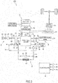
- FIG. 3 is a schematic diagram of the fuel cell system 100 according to a first embodiment of the present invention.
- the fuel cell system 100 includes the fuel cell stack 1, a cathode gas supplying/discharging device 2, an anode gas supplying/discharging device 3, a stack cooling device 4, a power system 5 and a controller 6.
- the fuel cell stack 1 is formed by laminating a plurality of fuel cells 10 and generates power necessary to drive a vehicle upon receiving the supply of the anode gas and the cathode gas.
- the fuel cell stack 1 includes an anode electrode side output terminal 1a and a cathode electrode side output terminal 1b as terminals for taking out power.
- the cathode gas supplying/discharging device 2 includes a cathode gas supply passage 21, a cathode gas discharge passage 22, a filter 23, an air flow sensor 24, a cathode compressor 25, a cathode pressure sensor 26, a water recovery device (hereinafter, referred to as a "WRD") 27 and a cathode pressure regulating valve 28.
- the cathode gas supplying/discharging device 2 supplies the cathode gas to the fuel cell stack 1 and discharges cathode off-gas discharged from the fuel cell stack 1 to outside.
- the cathode gas supply passage 21 is a passage in which the cathode gas to be supplied to the fuel cell stack 1 flows. One end of the cathode gas supply passage 21 is connected to the filter 23 and the other end is connected to a cathode gas inlet hole of the fuel cell stack 1.
- the cathode gas discharge passage 22 is a passage in which the cathode off-gas discharged from the fuel cell stack 1 flows. One end of the cathode gas discharge passage 22 is connected to a cathode gas outlet hole of the fuel cell stack 1 and the other end is an opening end.
- the cathode off-gas is mixture gas of the cathode gas and steam produced by the electrode reaction.
- the filter 23 removes foreign substances in the cathode gas to be taken into the cathode gas supply passage 21.
- the air flow sensor 24 is provided upstream of the cathode compressor 25 in the cathode gas supply passage 21.
- the air flow sensor 24 detects a flow rate of the cathode gas to be supplied to the cathode compressor 25 and finally supplied to the fuel cell stack 1 (hereinafter, referred to as a "stack supply flow rate"). It should be noted that a detection value of this air flow sensor 24 is referred to as a "detected stack supply flow rate" below if necessary.
- the cathode compressor 25 is provided in the cathode gas supply passage 21.
- the cathode compressor 25 takes air (outside air) as the cathode gas into the cathode gas supply passage 21 via the filter 23 and supplies it to the fuel cell stack 1.
- the cathode pressure sensor 26 is provided between the cathode compressor 25 and the WRD 27 in the cathode gas supply passage 21.
- the cathode pressure sensor 26 detects a pressure of the cathode gas (hereinafter, referred to as a "cathode pressure") to be supplied to the fuel cell stack 1. It should be noted that a detection value of this cathode pressure sensor 26 is referred to as a "detected cathode pressure" below if necessary.
- the WRD 27 is connected to each of the cathode gas supply passage 21 and the cathode gas discharge passage 22, recovers moisture in the cathode off-gas flowing in the cathode gas discharge passage 22 and humidifies the cathode gas flowing in the cathode gas supply passage 21 with that recovered moisture.
- the cathode pressure regulating valve 28 is provided downstream of the WRD 27 in the cathode gas discharge passage 22.
- the cathode pressure regulating valve 28 is controlled to open and close by the controller 6 and adjusts the pressure of the cathode gas to be supplied to the fuel cell stack 1 to a desired pressure. It should be noted that a throttle such as an orifice may be provided without providing the cathode pressure regulating valve 28.
- the anode gas supplying/discharging device 3 supplies the anode gas to the fuel cell stack 1 and discharges anode off-gas discharged from the fuel cell stack 1 to the cathode gas discharge passage 22.
- the anode gas supplying/discharging device 3 includes a high-pressure tank 31, an anode gas supply passage 32, an anode pressure regulating valve 33, an anode pressure sensor 34, an anode gas discharge passage 35, a buffer tank 36, a purge passage 37 and a purge valve 38.
- the high-pressure tank 31 stores the anode gas (hydrogen) to be supplied to the fuel cell stack 1 in a high-pressure state.
- the anode gas supply passage 32 is a passage for supplying the anode gas discharged from the high-pressure tank 31 to the fuel cell stack 1.
- One end of the anode gas supply passage 32 is connected to the high-pressure tank 31 and the other end is connected to an anode gas inlet hole of the fuel cell stack 1.
- the anode pressure regulating valve 33 is provided in the anode gas supply passage 32.
- the anode pressure regulating valve 33 is controlled to open and close by the controller 6 to adjust a pressure of the anode gas to be supplied to the fuel cell stack 1 to a desired pressure.
- the anode pressure sensor 34 is provided downstream of the anode pressure regulating valve 33 in the anode gas supply passage 32 and detects a pressure of the anode gas (hereinafter, referred to as an "anode pressure") to be supplied to the fuel cell stack 1.
- this anode pressure is used as a pressure in an anode system from the fuel cell stack 1 to the buffer tank 36.
- a detection value of this anode pressure sensor 34 is referred to as a "detected anode pressure" below if necessary.
- anode gas discharge passage 35 One end of the anode gas discharge passage 35 is connected to an anode gas outlet hole of the fuel cell stack 1 and the other end is connected to the buffer tank 36.
- Mixture gas of excess anode gas not used in the electrode reaction and inert gas containing nitrogen and moisture (produced water and stream) and permeated from the cathode gas flow passages 131 to the anode gas flow passages 121 (hereinafter, referred to as "anode off-gas”) is discharged to the anode gas discharge passage 35.
- the buffer tank 36 temporarily stores the anode off-gas flowing from the anode gas discharge passage 35.
- the anode off-gas pooled in the buffer tank 36 is discharged to the cathode gas discharge passage 22 through the purge passage 37 when the purge valve 38 is open.
- One end of the purge passage 37 is connected to the anode gas discharge passage 35 and the other end is connected to the cathode gas discharge passage 22.
- the purge valve 38 is provided in the purge passage 37.
- the purge valve 38 is controlled to open and close by the controller 6 and controls a flow rate of the anode off-gas discharged from the anode gas discharge passage 35 to the cathode gas discharge passage 22 (hereinafter, referred to as a "bypass flow rate").
- a flow rate of the anode off-gas discharged from the anode gas discharge passage 35 to the cathode gas discharge passage 22 hereinafter, referred to as a "bypass flow rate"
- the discharge of the anode off-gas to the cathode gas discharge passage 22 by opening the purge valve 38 is referred to as "purging" if necessary.
- the anode off-gas discharged to the cathode gas discharge passage 22 via the anode gas discharge passage 35 is mixed with the cathode off-gas in the cathode gas discharge passage 22 and is discharged to the outside of the fuel cell system 100. Since the anode off-gas contains excess hydrogen not used in the electrode reaction, a hydrogen concentration in discharged gas is set to be equal to or lower than a predetermined specific concentration by mixing the anode off-gas with the cathode off-gas and discharging the mixture gas to the outside of the fuel cell system 100.
- the stack cooling device 4 is a device for cooling the fuel cell stack 1 and keeping the fuel cell stack 1 at a temperature suitable for power generation.
- the stack cooling device 4 includes a cooling water circulation passage 41, a radiator 42, a bypass passage 43, a three-way valve 44, a circulation pump 45, a PTC heater 46, an inlet water temperature sensor 47 and an outlet water temperature sensor 48.
- the cooling water circulation passage 41 is a passage in which cooling water for cooling the fuel cell stack 1 is circulated, and one end is connected to a cooling water inlet hole of the fuel cell stack 1 and the other end is connected to a cooling water outlet hole of the fuel cell stack 1.
- the radiator 42 is provided in the cooling water circulation passage 41.
- the radiator 42 cools the cooling water discharged from the fuel cell stack 1.
- bypass passage 43 One end of the bypass passage 43 is connected to the cooling water circulation passage 41 and the other end is connected to the three-way valve 44 so that the cooling water can be circulated while bypassing the radiator 42.
- the three-way valve 44 is provided downstream of the radiator 42 in the cooling water circulation passage 41.
- the three-way valve 44 switches a circulation route of the cooling water according to the temperature of the cooling water. Specifically, when the temperature of the cooling water is higher than a predetermined temperature, the circulation route of the cooling water is so switched that the cooling water discharged from the fuel cell stack 1 is supplied to the fuel cell stack 1 again via the radiator 42. Conversely, when the temperature of the cooling water is lower than the predetermined temperature, the circulation route of the cooling water is so switched that the cooling water discharged from the fuel cell stack 1 is supplied to the fuel cell stack 1 again after flowing along the bypass passage 43 without via the radiator 42.
- the circulation pump 45 is provided downstream of the three-way valve 44 in the cooling water circulation passage 41 and circulates the cooling water.
- the PTC heater 46 is provided in the bypass passage 43.
- the PTC heater 46 is energized during the warm-up of the fuel cell stack 1 to increase the temperature of the cooling water.
- the inlet water temperature sensor 47 is provided near the cooling water inlet hole of the fuel cell stack 1 in the cooling water circulation passage.
- the inlet water temperature sensor 47 detects the temperature of the cooling water flowing into the fuel cell stack 1 (hereinafter, referred to as an "inlet water temperature").
- the outlet water temperature sensor 48 is provided near the cooling water outlet hole of the fuel cell stack 1 in the cooling water circulation passage.
- the outlet water temperature sensor 48 detects the temperature of the cooling water discharged from the fuel cell stack 1 (hereinafter, referred to as an "outlet water temperature").
- an average water temperature of the inlet water temperature and the outlet water temperature is used as a temperature in the fuel cell stack 1 (hereinafter, referred to as a "stack temperature").
- the power system 5 includes a current sensor 51, a voltage sensor 52, a travel motor 53, an inverter 54, a battery 55 and a DC/DC converter 56.
- the current sensor 51 detects a current extracted from the fuel cell stack 1 (hereinafter, referred to as an "output current").
- the voltage sensor 52 detects an inter-terminal voltage between the anode electrode side output terminal 1a and the cathode electrode side output terminal 1b (hereinafter, referred to as an "output voltage").
- the voltage sensor 52 detects a voltage of each fuel cell 10 constituting the fuel cell stack 1 (hereinafter, referred to as a "cell voltage”) and detects a total voltage of the fuel cells 10 as the output voltage. It should be noted that a voltage of each group composed of a plurality of the fuel cells 10 (cell group voltage) may be detected.
- the travel motor 53 is a three-phase alternating-current synchronous motor in which a permanent magnet is embedded in a rotor and a stator coil is wound around a stator.
- the travel motor 53 has a function as a motor to be rotationally driven upon receiving the supply of power from the fuel cell stack 1 and the battery 55 and a function as a generator for generating electromotive forces on opposite ends of the stator coil during the deceleration of the vehicle in which the rotor is rotated by an external force.
- the inverter 54 is composed of a plurality of semiconductor switches such as IGBTs (Insulated Gate Bipolar Transistors).
- the semiconductor switches of the inverter 54 are controlled to open and close by the controller 6, thereby converting direct-current power into alternating-current power or alternating-current power into direct-current power.
- the inverter 54 converts composite direct-current power of generated power of the fuel cell stack 1 and output power of the battery 55 into three-phase alternating-current power and supplies it to the travel motor 53 when the travel motor 53 functions as the motor.
- the inverter 54 converts regenerative power (three-phase alternating-current power) of the travel motor 53 into direct-current power and supplies it to the battery 55 when the travel motor 53 functions as the generator.
- the battery 55 is charged with a surplus of the generated power (output current ⁇ output voltage) of the fuel cell stack 1 and the regenerative power of the travel motor 53.
- the power charged into the battery 55 is supplied to auxiliary machines such as the cathode compressor 25 and the travel motor 53 if necessary.
- the DC/DC converter 56 is a bidirectional voltage converter for increasing and decreasing the output voltage of the fuel cell stack 1. By controlling the output voltage of the fuel cell stack 1 by the DC/DC converter 56, the output current of the fuel cell stack 1 and, consequently, the generated power are controlled.
- the controller 6 is configured by a microcomputer including a central processing unit (CPU), a read-only memory (ROM), a random access memory (RAM) and an input/output interface (I/O interface).
- CPU central processing unit
- ROM read-only memory
- RAM random access memory
- I/O interface input/output interface
- an accelerator stroke sensor 61 for detecting a depressed amount of an accelerator pedal (hereinafter, referred to as an "accelerator operation amount")
- an SOC sensor 62 for detecting a charge amount of the battery 55
- a battery temperature sensor 63 for detecting the temperature of the battery 55 besides the air flow sensor 24 and the like described above.
- the controller 6 calculates a target output current of the fuel cell stack 1 on the basis of the operating state of the fuel cell system 100. Specifically, the target output current is calculated on the basis of power required by the travel motor 53, power required by the auxiliary machines such as the cathode compressor 25, charge/discharge requests of the battery 55 and a warm-up request. Then, the controller 6 controls the output voltage of the fuel cell stack 1 by the DC/DC converter 56 so that the output current of the fuel cell stack 1 can reach the target output current.
- the controller 6 controls the cathode compressor 25, the circulation pump 45 and the like so that the electrolyte membranes 111 can have a degree of wetness (water content) suitable for power generation.
- an internal impedance (High Frequency Resistance; hereinafter, referred to as "HFR" of the fuel cell stack 1 correlated with the degree of wetness of the electrode membranes 111 is calculated, for example, by an alternating-current impedance method or the like.
- the cathode compressor 25, the circulation pump 45 and the like are controlled so that the HFR can reach a target HFR.
- the smaller the HFR the higher the degree of wetness of the electrolyte membranes 111.
- the target HFR is set at a predetermined value suitable for power generation determined in advance by an experiment or the like.
- FIG. 4 is a graph showing a relationship between the temperature of the fuel cell stack 1 and a current-voltage characteristic (hereinafter, referred to as an "IV characteristic") of the fuel cell stack 1.
- an IV characteristic shown by solid line is an IV characteristic after the warm-up of the fuel cell stack 1 is completed (hereinafter, referred to as a "reference IV characteristic").
- the IV characteristic of the fuel cell stack 1 changes according to the temperature of the fuel cell stack 1 and the output voltage when the output current of the same value is extracted from fuel cells becomes lower as the temperature of the fuel cell stack 1 decreases. Specifically, the power generation efficiency of the fuel cell stack 1 is reduced as the temperature of the fuel cell stack 1 decreases.
- the system minimum voltage V min is a voltage value which is set by an experiment or the like in advance and at which the drive of the travel motor 53 is obstructed if the output voltage of the fuel cell stack 1 drops below the system minimum voltage V min .
- the controller 6 stops the operation of the fuel cell system 100 as a fail-safe. Specifically, the controller 6 constitutes system stop unit that stops the fuel cell system 100 when the output voltage of the fuel cell stack 1 drops to or below the system minimum voltage V min (second predetermined value).
- a vehicle travel permit needs to be issued after confirming that the IV characteristic changing from moment to moment according to a temperature increase of the fuel cell stack 1 has reached an IV characteristic in which the output voltage of the fuel cell stack 1 does not drop below the system minimum voltage V min even if the travel motor 53 is driven, while the fuel cell stack 1 is warmed up.
- the vehicle travel permit needs to be issued after confirming that an IV characteristic in which the output voltage when the output current of the fuel cell stack 1 reaches a travel permit current does not drop below the system minimum voltage V min has been reached.
- the travel permit current is a value obtained by adding a predetermined margin to a minimum value of the output current at which the vehicle can start or travel smoothly by driving the travel motor 53, and set by an experiment or the like in advance.
- an upper limit value of the output current during warm-up in which no travel permit is issued (hereinafter, referred to as a "pre-travel permit upper limit current") is the sum of a current which can flow into the auxiliary machines (hereinafter, referred to as an "auxiliary machine consumption current") and a current which can flow into the battery 55.
- This pre-travel permit upper limit current is a value smaller than the travel permit current.
- the IV characteristic of the fuel cell stack 1 is estimated while the fuel cell stack 1 is warmed up and the vehicle travel permit is issued when the estimated IV characteristic reaches the predetermined IV characteristic in which the output voltage of the fuel cell stack 1 does not drop below the system minimum voltage V min even if the travel motor 53 is driven.
- FIG. 5 is a graph showing a method for estimating the IV characteristic of the fuel cell stack 1 during the start-up of the fuel cell system 100.
- a solid line represents a reference IV characteristic.
- a broken line represents an actual IV characteristic at a certain point during warm-up in which no travel permit is issued (hereinafter, referred to as an "actual IV characteristic").
- the output current can be increased only to the pre-travel permit upper limit current.
- the actual IV characteristic in an area not less than the pre-travel permit upper limit current cannot be actually detected.
- the output current by varying the output current with a specified variation width or larger for a section from the IV estimation accuracy ensuring request lower limit current I min to the pre-travel permit upper limit current (hereinafter, referred to as a "data acquisition area"), a plurality of each of the above three parameters (actual output current, reference voltage and actual output voltage) are acquired and the gradient A and the intercept B of equation (3) are calculated by a minimum square method. It should be noted that the output current is varied with the specified variation width or larger since estimation accuracy is more improved as the number of the acquired parameters increases.
- the IV characteristic is estimated on the basis of the parameters acquired while reducing the output current.
- the output current needs to be varied with the specified variation width or larger from the IV estimation accuracy ensuring request lower limit current I min to the pre-travel permit upper limit current in order to accurately estimate the IV characteristic during warm-up in which no travel permit is issued.
- the auxiliary machine consumption current is made as large as possible to promote the warm-up of the fuel cell stack 1 by self-heat generation.
- the output current is varied in estimating the IV characteristic
- data necessary for IV estimation is acquired basically by reducing the output current after the output current is increased to an output current for IV characteristic estimation larger than the auxiliary machine consumption current.
- the output voltage may largely drop if the output current is further increased from the auxiliary machine consumption current set to be large for warm-up. As a result, the output voltage may drop below the system minimum voltage V min . Further, the output voltage of the fuel cell stack 1 may drop below a predetermined minimum voltage necessary in operating the fuel cell system 100 and the fuel cell system 100 may have to be stopped.
- the output current is temporarily returned to the auxiliary machine consumption current and increased again to estimate the IV characteristic after the elapse of a predetermined time.
- FIGS. 6A and 6B are flow charts showing an IV characteristic estimation control according to the present embodiment to be executed during warm-up.
- Step S1 the controller 6 sets the target output current of the fuel cell stack 1 to a predetermined warm-up target current I WU and increases the output current to the warm-up target current I WU .
- the warm-up target current I WU is a value determined according to the consumption current of the auxiliary machines that can be driven during warm-up.
- the warm-up target current Iwu is increased by making the consumption current of the auxiliary machines during warm-up as large as possible to promote warm-up by self-heat generation of the fuel cell stack 1.
- Step S1 a processing of Step S1 performed by the controller 6 corresponds to warm-up unit that warms up the fuel cell stack 1 by adjusting power supplied to the auxiliary machines as loads such that the output current reaches the predetermined warm-up target current during the warm-up of the fuel cell stack 1.
- Step S2 the controller 6 determines whether or not the output current has increased to the warm-up target current I WU .
- the controller 6 performs a processing of Step S3 if the output current has increased to the warm-up target current I WU .
- the controller 6 returns to the processing of Step S1 to subsequently increase the output current to the warm-up target current I WU .
- Step S3 the controller 6 starts a count timer.
- Step S4 the controller 6 determines whether or not an elapsed time from the start of the count timer (hereinafter, referred to as a "count value") has become equal to or larger than an IV estimation start permit threshold value T L .
- An initial value of the count value is set at zero.
- the controller 6 performs a processing of Step S5 if the count value is not smaller than the IV estimation start permit threshold value T L .
- the controller 6 performs a processing of Step S4 until the count value becomes equal to or larger than the IV estimation start permit threshold value T L if the count value is below the IV estimation start permit threshold value T L .
- Step S5 the controller 6 stops the count timer and resets the count value to zero.
- Step S6 the controller 6 performs a battery request limit current calculation process.
- This process is a process of calculating an upper limit value (hereinafter, referred to as a "battery request upper limit current I BH ) and a lower limit value (hereinafter, referred to as a “battery request lower limit current I BL ) of the output current set according to the state of the battery 55.
- the detail of the battery request limit current calculation process is described with reference to a flow chart of FIG. 7 .
- FIG. 7 is a flow chart showing the battery request limit current calculation process.
- Step S61 the controller 6 calculates a maximum value of the current that can be extracted from the battery 55 (hereinafter, referred to as a "dischargeable current value”) and a maximum value of the current that can flow into the battery 55 (hereinafter, referred to as a “chargeable current value”) on the basis of a battery charge amount and a battery temperature.
- a dischargeable current value a maximum value of the current that can be extracted from the battery 55
- Step S62 the controller 6 calculates a current value obtained by adding the chargeable current value to the warm-up target current I WU as the battery request upper limit current I BH .
- the battery request upper limit current I BH is such a current value that the battery 55 is overcharged and may be deteriorated if the output current becomes larger than that.
- Step S63 the controller 6 calculates a current value obtained by subtracting the dischargeable current value from the warm-up target current I WU as the battery request lower limit current I BL .
- the battery request lower limit current I BL is such a current value that the battery 55 is over-discharged and may be deteriorated if the output current becomes smaller than that.
- the IV characteristic estimation control is described again below, referring back to the flow chart of FIG. 6A .
- Step S7 the controller 6 performs the system request limit current calculation process.
- This process is a process of calculating an upper limit value (hereinafter, referred to as a "system request upper limit current I SH ) and a lower limit value (hereinafter, referred to as a "system request lower limit current I SL ) of the output current set according to the operating state of the fuel cell system 100.
- the process performed by the controller 6 corresponds to limit value setting unit that sets at least one of an upper limit value and a lower limit value of the output current on the basis of the operating state of the fuel cell system 100.
- the detail of the system request limit current calculation process is described with reference to a flow chart of FIG. 8 .
- FIG. 8 is a flow chart showing the system request limit current calculation process.
- Step S71 the controller 6 refers to a map of FIG. 9 and calculates an oxygen partial pressure reduction prevention request upper limit value on the basis of the detected cathode pressure, the detected stack temperature and the detected stack supply flow rate.
- the oxygen partial pressure reduction prevention request upper limit value is a maximum value of the output current that may be extracted from the fuel cell stack 1 when a flow rate of the cathode gas to be supplied to the fuel cell stack 1 is the detected stack supply flow rate. If the current larger than the oxygen partial pressure reduction prevention request upper limit value is extracted, an oxygen consumption amount may become too large relative to a cathode gas supply amount, whereby the oxygen partial pressure in the cathode gas flow passages 131 may decrease and the output voltage may largely decrease.
- Step S72 the controller 6 refers to a map of FIG. 10 and calculates a cell voltage reduction prevention request upper limit value on the basis of an average cell voltage and a minimum cell voltage.
- the cell voltage reduction prevention request upper limit value is a maximum value of the output current to prevent the cell voltage from dropping below a predetermined cell voltage lower limit threshold value set in advance. If power generation is continued in a state where the cell voltage is below the cell voltage lower limit threshold value, the fuel cells 10 may be deteriorated such as due to an overheated state of the fuel cells 10.
- Step S73 the controller 6 refers to a table of FIG. 11 and calculates an output voltage reduction prevention request upper limit value on the basis of the output voltage.
- the output voltage reduction prevention request upper limit value is a maximum value of the output current to prevent the output voltage from dropping below an output voltage lower limit threshold value set in advance. If the output current is increased in a state where the output voltage is below the output voltage lower limit threshold value, the output voltage may largely decrease and the fuel cells 10 may be deteriorated.
- Step S74 the controller 6 calculates the smallest one of the oxygen partial pressure reduction prevention request upper limit value, the cell voltage reduction prevention request upper limit value and the output voltage reduction prevention request upper limit value as the system request upper limit current I SH .
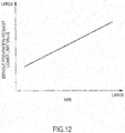
- Step S75 the controller 6 refers to a table of FIG. 12 and calculates a dry-out prevention request lower limit value on the basis of the HFR.
- the dry-out prevention request lower limit value is a lower limit value of the output current set to prevent the occurrence of a dry-out phenomenon in which power generation efficiency is reduced due to the dry-out of the electrolyte membranes 111.
- Step S76 the controller 6 calculates the larger one of the dry-out prevention request lower limit value and a predetermined high potential deterioration prevention request lower limit value determined by an experiment or the like in advance as the system request lower limit current I SL .
- the high potential deterioration prevention request lower limit value is a lower limit value of the output current set to prevent the occurrence of a high potential deterioration phenomenon in which a catalyst of an electrode catalyst layer is covered with an oxide film and power generation efficiency is reduced when the cell voltage becomes a high potential.
- the IV characteristic estimation control is described again below, referring back to the flow chart of FIG. 6A .
- Step S8 the controller 6 performs a process of calculating a maximum value (hereinafter, referred to as a "maximum current variation width") ⁇ I max of the variation width of the output current (hereinafter, referred to as a "current variation width").
- a maximum current variation width a maximum value
- current variation width a current variation width
- FIG. 13 is a flow chart showing the maximum current variation width calculation process.
- Step S81 the controller 6 calculates an upper limit value of the output current in varying the output current during IV estimation (hereinafter, referred to as an "IV estimation upper limit current I c1 "). Specifically, the controller 6 calculates the smaller one of the battery request upper limit current I BH and the system request upper limit current I SH as the IV estimation upper limit current I c1 .
- Step S82 the controller 6 calculates a lower limit value of the output current in varying the output current during IV estimation (hereinafter, referred to as an "IV estimation lower limit current I c2 "). Specifically, the largest one of the battery request lower limit current I BL , the system request lower limit current I SL and the IV estimation accuracy ensuring request lower limit current I min is calculated as the IV estimation lower limit current I c2 .
- Step S83 the controller 6 calculates a difference value between the IV estimation upper limit current I c1 and the IV estimation lower limit current I c2 as the maximum current variation width ⁇ I max .
- the IV characteristic estimation control is described again below, referring back to the flow chart of FIG. 6A .
- Step S9 the controller 6 determines whether or not the maximum current variation width ⁇ I max is not smaller than a predetermined current variation width ⁇ I necessary to ensure the estimation accuracy of the IV characteristic.
- the controller 6 performs a processing of Step S10 if the maximum current variation width ⁇ I max is not smaller than the current variation width ⁇ I.
- the controller 6 returns to the processing of Step 6 if the maximum current variation width ⁇ I max is smaller than the current variation width ⁇ I.
- the controller 6 sets the target output current of the fuel cell stack 1 to the IV estimation upper limit current I c1 to start the IV estimation process and increases the output current from the warm-up target current I WU to the IV estimation upper limit current I c1 .
- the IV estimation process performed by the controller 6 corresponds to IV estimation unit that varies the output current of the fuel cell stack 1 with a predetermined width by adjusting power supplied to the auxiliary machines as loads during the warm-up of the fuel cell stack 1 and estimating the IV characteristic of the fuel cell stack 1 on the basis of at least two sets of the output current value and the output voltage value detected while the output current is varied.
- Step S11 the controller 6 determines whether or not the output current has increased to the IV estimation upper limit current I c1 .
- the controller 6 performs a processing of Step S18 if the output current has increased to the IV estimation upper limit current I c1 .
- the controller 6 performs a processing of Step S12 if the output current is being increased to the IV estimation upper limit current I c1 .
- Step S12 the controller 6 determines whether or not the output current is not higher than the predetermined voltage V 1 . Specifically, it is determined whether or not the output voltage has dropped to the predetermined voltage V 1 while the output current is being increased to the IV estimation upper limit current I c1 .
- This predetermined voltage V 1 is a voltage value higher than the system minimum voltage V min and a threshold value set to prevent a drop of the output voltage to the system minimum voltage V min with an increase of the output current.
- the processing of Step S12 performed by the controller 6 corresponds to judgment unit that judges whether or not a state of power generation of the fuel cell stack 1 is in a good state where the IV characteristic can be estimated during the execution of the IV estimation unit.
- the controller 6 performs a processing of Step S13 if the output voltage has dropped to the predetermined voltage V 1 . On the other hand, the controller 6 performs a processing of Step S15 unless the output voltage has dropped to the predetermined voltage V 1 .
- a predetermined cell voltage V 2 is equivalent to a value obtained by dividing the predetermined voltage V 1 by a total cell number.
- Step S 13 the controller 6 stops the IV estimation process since the output voltage may further decrease from the predetermined voltage V 1 and drop below the system minimum voltage V min if the output current is increased further than this. Specifically, the controller 6 stops the execution of the IV estimation process if the state of power generation of the fuel cell stack 1 is determined to be not in the good state. Specifically, the controller 6 sets the target output current to the warm-up target current I WU and reduces the output current increased toward the IV estimation upper limit current I c1 toward the warm-up target current I WU . It should be noted that the processing of Step S13 performed by the controller 6 corresponds to an IV estimation stop step of stopping the execution of the IV estimation process on the basis of the output voltage of the fuel cell stack 1.
- Step S14 the controller 6 sets the IV estimation start permit threshold value T L to a first predetermined value T m1 . Then, a return is made to Step S3 to start the count timer, and the IV estimation process is resumed when the count value becomes equal to or larger than the first predetermined value T m1 .
- the first predetermined value T m1 is set at a relatively large value of, for example, about several tens of seconds. This is because a drop of the output voltage to the predetermined voltage V 1 while the output current is being increased toward the IV estimation upper limit current I c1 can be thought to indicate a state where the warm-up is not very much in progress and a deviation between the actual IV characteristic and the reference IV characteristic is large. Specifically, a state where the warm-up of the fuel cell stack 1 is still insufficient and the IV characteristic is poor can be thought.
- the output voltage may drop to the predetermined voltage V 1 again and the IV estimation process may have to be stopped.
- the IV estimation process is started, the output current is increased from the warm-up target current I WU to the IV estimation upper limit current I c1 and an excess current that cannot flow into the auxiliary machines flows into the battery 55.
- the IV estimation process is uselessly performed many times, the battery charge amount increases and the battery request upper limit current I BH gradually decreases, whereby it may become impossible to ensure the predetermined current variation width ⁇ I. Further, burdens of the battery 55 also increase.
- a certain time interval is provided in such a state and the IV estimation process is performed after waiting for the recovery of the IV characteristic. This can prevent the IV estimation process from being uselessly performed many times.
- the first predetermined value T m1 is a fixed value determined in advance in the present embodiment, it may be a variable value.
- the first predetermined value T m1 may be set on the basis of the output current value when the output voltage reaches the predetermined voltage V 1 .
- the first predetermined value T m1 is desirably increased as the output current value decreases. This is because it can be judged that the smaller the output current value when the output voltage reaches the predetermined voltage V 1 , the larger the deviation between the actual IV characteristic and the reference IV characteristic and the poorer the IV characteristic.
- Step S15 the controller 6 calculates the system request upper limit current I SH again.
- Step S16 the controller 6 compares the magnitudes of the target output current set in Step S10, i.e. the IV estimation upper limit current I c1 and the system request upper limit current I SH calculated in Step S15. It should be noted that a processing of Step S16 corresponds to excess determination unit that determines whether or not the output current reaches the upper limit value (system request upper limit current I SH ) when the output current is varied with the predetermined variation width by the IV estimation process.
- the controller 6 performs a processing of Step S17 if the IV estimation upper limit current I c1 is larger than the system request upper limit current I SH .
- the controller 6 returns to the processing of Step S11 if the IV estimation upper limit current I c1 is not larger than the system request upper limit current I SH .
- the controller 6 continues the execution of the IV estimation process if the state of power generation of the fuel cell stack 1 is judged to be in the good state.
- Step S17 the controller 6 stops the IV estimation process. Specifically, the target output current is set to the warm-up target current I WU and the output current increased toward the IV estimation upper limit current I c1 is reduced toward the warm-up target current I WU . It should be noted that a processing of Step S17 performed by the controller 6 corresponds to second IV estimation stop unit that stops the execution of the IV estimation process when the output current is determined to reach the upper limit value (system request upper limit current I SH ).
- the IV estimation process is stopped in Step S17 for the following reason.
- the IV estimation upper limit current I c1 may become larger than the system request upper limit current I SH , for example, if the system request upper limit current I SH is updated and reduced while the output current is being increased toward the IV estimation upper limit current I c1 . If the output current is increased to the IV estimation upper limit current I c1 beyond the system request upper limit current I SH in this case, it may lead to an extreme voltage drop or the deterioration of the fuel cells. Thus, it is not desirable to increase the output current to the IV estimation upper limit current I c1 .
- Step S6 determine again whether or not the predetermined current variation width ⁇ I can be ensured and the IV estimation process is performed.
- Step S18 the controller 6 sets a current value obtained by subtracting the current variation width ⁇ I from the IV estimation upper limit current I c1 (hereinafter, referred to as an "IV estimation load reducing target current I tL ”) as the target output current of the fuel cell stack 1. Then, the output current is reduced from the IV estimation upper limit current I c1 to the IV estimation load reducing target current I tL .
- Step S19 the controller 6 appropriately acquires the aforementioned three parameters (actual output current, reference voltage and actual output voltage) while the output current is being reduced.
- Step S20 the controller 6 determines whether or not the output current has been reduced to the IV estimation load reducing target current I tL .
- the controller 6 performs a processing of Step S24 if the output current has been reduced to the IV estimation load reducing target current I tL .
- the controller 6 performs a processing of Step S21 if the output current is being reduced to the IV estimation load reducing target current I tL .
- Step S21 the controller 6 calculates the system request lower limit current I SL again.
- Step S22 the controller 6 compares the magnitudes of the target output current set in Step S18, i.e. the IV estimation load reducing lower limit current I tL and the system request lower limit current I SL calculated in Step S21. Then, the controller 6 performs a processing of Step S23 if the system request lower limit current I SL is larger than the IV estimation load reducing target current I tL . On the other hand, the controller 6 returns to the processing of Step S19 if the system request lower limit current I SL is not higher than the IV estimation load reducing target current I tL .
- Step S22 performed by the controller 6 corresponds to excess determination unit that determines whether or not the output current reaches the lower limit value (system request lower limit current I SL ) when the output current is varied with the predetermined width by the IV estimation process.
- Step S23 the controller 6 stops the IV estimation process. Specifically, the target output current is set to the warm-up target current I WU and the output current reduced toward the IV estimation loading reading target current I tL is controlled toward the warm-up target current I WU . It should be noted that a processing of Step S23 performed by the controller 6 corresponds to second IV estimation stop unit that stops the execution of the IV estimation process when the output current is determined to reach the lower limit value (system request lower limit current I SL ).
- the IV estimation process is stopped in Step S23 for the following reason.
- the system request lower limit current I SL may be, for example, updated and increased and become larger than IV estimation load reducing target current I tL . If the output current is reduced below the system request lower limit current I SL in this case, it may cause the dry-out phenomenon or the high potential deterioration phenomenon. Thus, it is not desirable to reduce the output current to the IV estimation load reducing target current I tL .
- Step S6 determine again whether or not the predetermined current variation width ⁇ I can be ensured and the IV estimation process is performed.
- Step S24 the controller 6 finishes the acquisition of the parameters.
- Step S25 the controller 6 sets the target output current to the warm-up target current I WU and controls the output current toward the warm-up target current I WU .
- Step S26 the controller 6 estimates the IV characteristic on the basis of a plurality of acquired parameter groups. As just described, the controller 6 performs the IV estimation process in a series of processings from Step S1 to Step S26.
- the series of processings from Step S1 to Step S26 performed by the controller 6 correspond to an IV estimation step of varying the output current of the fuel cell stack 1 with the predetermined width by adjusting power supplied to the loads during the warm-up of the fuel cell stack 1 and estimating the IV characteristic of the fuel cell stack 1 on the basis of at least two sets of the output current value and the output voltage value detected while the output current is varied.
- Step S27 the controller 6 determines whether or not the travel permit is issuable. Specifically, the controller 6 determines whether or not the estimated IV characteristic is the predetermined IV characteristic in which the output voltage of the fuel cell stack 1 does not drop below the system minimum voltage V min even if the travel motor 53 is driven. It should be noted that a processing of Step S27 performed by the controller 6 corresponds to IV characteristic determination unit that determines whether or not the IV characteristic estimated by the IV estimation process has reached the predetermined IV characteristic.
- the controller 6 performs a processing of Step S28 if the travel permit is issuable while performing a processing of Step S29 if it is not.
- Step S28 the controller 6 issues the travel permit and finishes the IV characteristic estimation control.
- Step S29 the controller 6 sets the IV estimation start permit threshold value T L to a second predetermined value T m2 . Then, a return is made to Step S3 to start the count timer, and the IV estimation process is resumed when the count value becomes equal to or larger than the second predetermined value T m2 .
- the second predetermined value T m2 is set, for example, at about several seconds, and a value smaller than the first predetermined value T m1 . This is because, if the travel permit could not be issued although the IV characteristic could be estimated, the IV characteristic can be estimated even if the IV estimation process is resumed in a relatively short time interval unlike the case where the output voltage drops to or below the predetermined voltage V 1 and the IV estimation process is stopped. Thus, whether or not the travel permit is issuable can be more quickly determined when the IV estimation process is resumed in a relative short time interval.
- FIG. 14 is a time chart showing an example of the operation of the IV characteristic estimation control according to the present embodiment.
- the output current is controlled to the warm-up target current Iwu at time t1 (Yes in S2).
- the controller 6 starts the IV estimation process. Specifically, the target output current is set to the IV estimation upper limit current I c1 and the output current is increased from the warm-up target current I WU to the IV estimation upper limit current I c1 .
- the controller 6 stops the IV estimation process. Specifically, the target output current is set to the warm-up target current Iwu and the output current being increased toward the IV estimation upper limit current I c1 is reduced toward the warm-up target current I WU .
- a drop of the output voltage to the predetermined voltage V 1 while the output current is being increased toward the IV estimation upper limit current I c1 as just described can be thought to indicate the state where the warm-up is not very much in progress and the IV characteristic is poor.
- the controller 6 sets the IV estimation start permit threshold value T L to the first predetermined value T m1 larger than the second predetermined value T m2 and starts the count timer.
- the controller 6 resumes the IV estimation process. Specifically, the target output current is set to the IV estimation upper limit current I c1 and the output current is increased from the warm-up target current I WU toward the IV estimation upper limit current I c1 .
- the controller 6 sets the target output current to the IV estimation load reducing target current I tL and reduces the output current from the IV estimation upper limit current I c1 toward the IV estimation load reducing target current I tL . Then, the controller 6 appropriately acquires the aforementioned three parameters (actual output current, reference voltage and actual output voltage) while the output current is being reduced.
- the controller 6 estimates the IV characteristic on the basis of the acquired parameters and determines whether or not the travel permit is issuable.
- the controller 6 sets the IV estimation start permit threshold value T L to the second predetermined value T m2 and starts the count timer.
- the controller 6 sets the IV estimation start permit threshold value T L to the second predetermined value T m2 and starts the count timer.
- FIG. 15 is a time chart showing another example of the operation of the IV characteristic estimation control according to the present embodiment.
- the battery request upper limit current I BH is smaller than the system request upper limit current I SH at time t11, the battery request upper limit current I BH is calculated as the IV estimation upper limit current I c1 .
- a difference value between the battery request upper limit current I BH and the IV estimation lower limit current I c2 is the maximum current variation width ⁇ I max .
- the system request upper limit current I SH is smaller than the battery request upper limit current I BH at time t13, the system request upper limit current I SH is calculated as the IV estimation upper limit current I c1 .
- a difference value between system request upper limit current I SH and the IV estimation lower limit current I c2 is the maximum current variation width ⁇ I max .
- the controller 6 Since the maximum current variation width ⁇ I max calculated at time t13 is not smaller than the predetermined current variation width ⁇ 1, the controller 6 resumes the IV estimation process. Then, the controller 6 estimates the IV characteristic on the basis of the parameters acquired between time t14 and time t15. If the travel permit could not be issued as a result of estimation, the IV estimation process is resumed after an elapsed time from time t15 becomes equal to or larger than the second predetermined value T m2 at time t16.
- the fuel cell system 100 includes the fuel cell stack 1 and the loads such as the auxiliary machines connected to the fuel cell stack 1 and the battery 55, and executes the IV estimation process that changes the output current of the fuel cell stack 1 with the predetermined width by adjusting power supplied to the loads during the warm-up of the fuel cell stack 1 and estimating the IV characteristic of the fuel cell stack 1 on the basis of at least two sets of the output current value and the output voltage value detected while the output current is changed.
- the fuel cell system 100 stops the execution of the IV estimation on the basis of power output from the fuel cell stack 1, i.e. an output of the fuel cell stack 1 during the execution of the IV estimation. For example, the fuel cell system 100 determines on the basis of the output of the fuel cell stack 1 whether or not the state of power generation of the fuel cell stack 1 is in the good state suitable for the execution of the IV estimation process and stops the execution of the IV estimation if the state of power generation of the fuel cell stack 1 is determined not to be in the good state suitable for the execution of the IV estimation process.
- the fuel cell system 100 determines a state not good for the execution of the IV estimation process and stops the execution of the IV estimation process in a state of power generation where the output voltage of the fuel cell stack 1 is likely to extremely decrease, i.e. a state of power generation where a so-called voltage drop is likely to occur. This can prevent the deterioration of the state of power generation of the fuel cell stack 1 due to a voltage drop of the fuel cell stack 1 according to the execution of the IV estimation process.
- the present embodiment it is possible to avoid that the power generation characteristic of the fuel cell stack 1 estimated by the IV estimation process is deteriorated due to a change in the output of the fuel cell stack 1.
- the fuel cell system 100 stops the execution of the IV estimation when the output voltage of the fuel cell stack 1 drops to or below the predetermined voltage V 1 (first predetermined value). This can suppress a drop of the output voltage to or below the predetermined voltage V 1 during the execution of the IV estimation. Thus, a drop of the output voltage below the system minimum voltage during the estimation of the IV characteristic can be prevented, for example, by setting the predetermined voltage V 1 to be not smaller than the system minimum voltage.
- the fuel cell system 100 sets the predetermined voltage V 1 (first predetermined value) at a value larger than the system minimum voltage V min (second predetermined value). Thus, it can be reliably suppressed that the output voltage drops to or below the system minimum voltage V min and the fuel cell system 100 is stopped during the execution of the IV estimation.
- the fuel cell system 100 executes the IV estimation again after the elapse of the first predetermined period T m1 when the output voltage drops to or below the predetermined voltage V 1 and the execution of the IV estimation is stopped.
- the battery charge amount gradually increases or decreases, whereby it may not be possible to provide the current variation width ⁇ I necessary to ensure IV estimation accuracy and execute the IV estimation itself. Further, the battery 55 itself may be deteriorated.
- the first predetermined period T m1 is set to become longer, for example, as the output current value becomes smaller on the basis of the output current value when the output voltage reaches the predetermined voltage V 1 , it can be further suppressed that the IV estimation is uselessly executed. This is because it can be judged that the smaller the output current value when the output voltage reaches the predetermined voltage V 1 , the larger the deviation between the actual IV characteristic and the reference IV characteristic and the poorer the IV characteristic.
- the fuel cell system 100 determines whether or not the IV characteristic estimated by the IV estimation unit has reached the predetermined IV characteristic in which the travel permit is issuable. If it is determined that the predetermined IV characteristic has not been reached as a result of this determination, the IV estimation is executed again after the elapse of the second predetermined period T m2 .
- the first predetermined period T m1 is set at a value longer than the second predetermined period T m2 .
- the IV estimation is executed again after a certain time interval if the execution of the IV estimation is stopped halfway, i.e. the warm-up is not very much in progress.
- the IV estimation is executed again only after a time interval, which is not very long, if the IV characteristic could be estimated by the IV estimation, i.e. the warm-up is in progress to a certain extent.
- the IV estimation is executed again only after a time interval which is not very long.
- the fuel cell system 100 sets at least one of the system request upper limit current I SH (upper limit value of the output current) and the system request lower limit current I SH (lower limit value of the output current) on the basis of the operating state of the fuel cell system 100. Then, whether or not the output current reaches the system request upper limit current I SH or the system request lower limit current I SH in the case of varying the output current with the predetermined width by the IV estimation (S16, S22). When the output current is determined to reach the system request upper limit current I SH or the system request lower limit current I SH , the execution of the IV estimation is stopped.
- the system request upper limit current I SH upper limit value of the output current
- I SH lower limit value of the output current
- the output current reaches the system request upper limit current I SH or the system request lower limit current I SL when the output current is varied with the predetermined width by the IV estimation, the output current cannot be varied any further. Then, the output current may not be able to be varied with the predetermined width and the estimation accuracy of the IV characteristic is reduced.
- the estimation accuracy of the IV characteristic can be ensured by stopping the execution of the IV estimation.
- the fuel cell system 100 warms up the fuel cell stack 1 by adjusting the power supplied to the loads such that the output current reaches the predetermined warm-up target current I WU during the warm-up of the fuel cell stack 1.
- the power supplied to the loads is adjusted to increase the output current from the warm-up target current Iwu and the output current of the fuel cell stack 1 is varied with the predetermined width.
- the fuel cell system 100 judges whether or not the output voltage has dropped to or below the predetermined voltage V 1 (first predetermined value) when the output current is being increased.
- the output voltage decreases with an increase of the output current.
- a computational load of the controller 6 can be reduced by making such a judgment only in a scene where the output voltage decreases.
- an IV characteristic is estimated by observing a change of an output voltage when an output current is changed with a specified current width or larger in an area where an output current of a fuel cell system 1 is not smaller than a predetermined current, utilizing that a relationship of the output current and the output voltage can be approximated by a linear function in that area.
- the output current needs to be varied with a specified variation width or larger from the IV estimation accuracy ensuring request lower limit current I min to the pre-travel permit upper limit current as shown in FIG. 5 .
- the pre-travel permit upper limit current by making the auxiliary machine consumption current as large as possible.
- the warm-up of a fuel cell stack 1 by self-heat generation can also be promoted by making the auxiliary machine consumption current larger.
- the consumption current of the auxiliary machines connected to the fuel cell stack 1 is increased and the output current is caused to flow also into the battery 55 in order to change the output current with the specified current width or larger in the area where the output current is not smaller than the predetermined current.
- the consumption current of the auxiliary machines cannot be sufficiently increased. If it is attempted to change the output current with the specified current width or larger in this case, the output current may have to be changed in an area below the predetermined current. Since the relationship of the output current and the output voltage cannot be approximated by a linear function in the area where the output current is below the predetermined current, the estimation accuracy of the IV characteristic is deteriorated if the output current has to be changed in the area below the predetermined current.
- the auxiliary machine consumption current cannot be increased such as because the consumption current of the PTC heater 46 has to be reduced to prevent the bumping of cooling water.
- the pre-travel permit upper limit current is also reduced.
- the output current may drop below the IV estimation accuracy ensuring request lower limit current I min , for example, if the output current is reduced by a specified amount from the pre-travel permit upper limit current.
- a controller 6 temporarily stops the estimation of the IV characteristic if the output current is judged to drop below the IV estimation accuracy ensuring request lower limit current I min when the output current is reduced by a specified amount after being increased to estimate the IV characteristic.
- FIGS. 16A and 16B are a flow chart showing an IV characteristic estimation control according to the second embodiment executed during warm-up.
- Step S31 the controller 6 sets a target output current of the fuel cell stack 1 to a predetermined warm-up target current I WU and increases an output current to the warm-up target current I WU .
- the warm-up target current I WU is a value determined according to a consumption current of auxiliary machines that can be driven during warm-up.
- the warm-up target current Iwu changes according to the consumption current of a cathode compressor 25 and a PTC heater 46 and is normally set at a high value to promote the warm-up of the fuel cell stack 1.
- the warm-up target current I WU is set at a value lower than normal if necessary such as when the consumption current of the cathode compressor of the PTC heater 46 needs to be reduced to prevent the bumping of cooling water.
- Step S32 the controller 6 determines whether or not the output current has increased to the warm-up target current I WU .
- the controller 6 performs a processing of Step S33 if the output current has increased to the warm-up target current I WU .
- the controller 6 returns to the processing of Step S31 to subsequently increase the output current to the warm-up target current I WU .
- Step S33 the controller 6 starts a count timer.
- Step S34 the controller 6 determines whether or not an elapsed time from the start of the count timer (hereinafter, referred to as a "count value”) has become equal to or larger than an IV estimation start permit threshold value T L .
- An initial value of the count value is set at zero. The controller 6 repeats this processing until the count value becomes equal to or larger than the IV estimation start permit threshold value T L .
- Step S35 the controller 6 stops the count timer and resets the count value to zero.
- Step S36 the controller 6 performs a battery request limit current calculation process.
- This process is a process of calculating an upper limit value (hereinafter, referred to as a "battery request upper limit current I BH ) and a lower limit value (hereinafter, referred to as a “battery request lower limit current I BL ) of the output current set according to a state of a battery 55.
- the detail of the battery request limit current calculation process is described with reference to a flow chart of FIG. 17 .
- FIG. 17 is a flow chart showing the battery request limit current calculation process.
- Step S361 the controller 6 calculates a maximum value of the current that can be extracted from the battery 55 (hereinafter, referred to as a "dischargeable current value”) and a maximum value of the current that can flow into the battery 55 (hereinafter, referred to as a “chargeable current value”) on the basis of a battery charge amount and a battery temperature.
- Step S362 the controller 6 calculates a current value obtained by adding the chargeable current value to the warm-up target current I WU as the battery request upper limit current I BH .
- the battery request upper limit current I BH is such a current value that the battery 55 is overcharged and may be deteriorated if the output current becomes larger than that.
- This battery request upper limit current I BH corresponds to the aforementioned pre-travel permit upper limit current.
- Step S363 the controller 6 calculates a current value obtained by subtracting the dischargeable current value from the warm-up target current I WU as the battery request lower limit current I BL .
- the battery request lower limit current I BL is such a current value that the battery 55 is over-discharged and may be deteriorated if the output current becomes smaller than that.
- the IV characteristic estimation control is described again below, referring back to the flow chart of FIG. 16A .
- Step S37 the controller 6 calculates a maximum current variation width ⁇ I max . Specifically, the controller 6 calculates a difference value between the battery request upper limit current I BH and the battery request lower limit current I BL as the maximum current variation width ⁇ I max .
- Step S38 the controller 6 determines whether or not the maximum current variation width ⁇ I max is not smaller than a predetermined current variation width ⁇ I necessary to ensure the estimation accuracy of the IV characteristic.
- the controller 6 performs a processing of Step S39 if the maximum current variation width ⁇ I max is not smaller than the predetermined current variation width ⁇ I.
- Step S44 a return is made to a processing of Step S44 if the maximum current variation width ⁇ I max is below predetermined current variation width ⁇ I.
- Step S39 the controller 6 calculates an IV estimation load increasing target current I tH . Specifically, the controller 6 calculates the smaller one of a current value I bt obtained by adding the current variation width ⁇ I to the warm-up target current I WU and the battery request upper limit current I BH as the IV estimation load increasing target current I tH .
- the IV estimation load increasing target current I tH is a target value on an upper side in varying the output current.
- Step S40 the controller 6 sets the target output current of the fuel cell stack 1 to the IV estimation load increasing target current I tH and increases the output current from the warm-up target current I WU toward the IV estimation load increasing target current I tH .
- Step S41 the controller 6 determines whether or not the output current has increased to the IV estimation load increasing target current I tH .
- the controller 6 repeats this processing until the output current increases to the IV estimation load increasing target current I tH .
- Step S42 the controller 6 calculates an IV estimation load reducing target current I tL . Specifically, the controller 6 calculates a current value obtained by subtracting the current variation width ⁇ I from the IV estimation load increasing target current I tH as the IV estimation load reducing target current I tL .
- the IV estimation load reducing target current I tL is a target value on a lower side in varying the output current.
- Step S43 the controller 6 determines whether or not the IV estimation load reducing target current I tL is not smaller than the IV estimation accuracy ensuring request lower limit current I min . It should be noted that a processing of Step S43 performed by the controller 6 corresponds to judgment unit for judging whether or not a state of power generation of the fuel cell stack 1 is in a good state where the IV characteristic can be estimated during the execution of the IV estimation.
- the controller 6 performs a processing of Step S48 if the IV estimation load reducing target current I tL is not smaller than the IV estimation accuracy ensuring request lower limit current I min .
- the controller proceeds to a processing of Step S44 to stop the IV estimation process if the IV estimation load reducing target current I tL is below the IV estimation accuracy ensuring request lower limit current I min .
- the controller 6 continues to execute the IV estimation process if the state of power generation of the fuel cell stack 1 is judged to be in a good state while stopping the execution of the IV estimation process unless the state of power generation of the fuel cell stack 1 is judged to be in the good state.
- the controller 6 sets a minimum value of the output current determined in advance by an experiment or the like to ensure the estimation accuracy of the IV characteristic, i.e. a fixed value as the IV estimation accuracy ensuring request lower limit current I min .
- the controller 6 may change the IV estimation accuracy ensuring request lower limit current I min according to a condition of recovery of the IV characteristic of the fuel cell stack 1, i.e. a progress of the warm-up of the fuel cell stack 1. This is because the IV estimation accuracy ensuring request lower limit current I min tends to decrease as the warm-up of the fuel cell stack 1 progresses and the IV characteristic is recovered.
- the controller 6 may, for example, set the IV estimation accuracy ensuring request lower limit current I min at a smaller value as an elapsed time from the start-up of the fuel cell system 100 becomes longer. Alternatively, the controller 6 may set the IV estimation accuracy ensuring request lower limit current I min at a smaller value as the stack temperature increases. As just described, the controller 6 constitutes minimum value setting unit for setting a minimum value of the output current (IV estimation accuracy ensuring request lower limit current I min ) in changing the output current of the fuel cell stack 1 by the IV estimation process to ensure IV estimation accuracy by the IV estimation process.
- the smaller one of the current value I bt obtained by adding the current variation width ⁇ I to the warm-up target current I WU and the battery request upper limit current I BH is calculated as the IV estimation load increasing target current I tH .
- a case where the battery request upper limit current I BH is calculated as the IV estimation load increasing target current I tH is a case where the output current cannot be increased from the warm-up target current I WU to the current value I bt obtained by adding the current variation width ⁇ I to the warm-up target current I WU and an upper limit of the output current is limited to the battery request upper limit current I BH since the battery charge amount is large and the amount of power receivable by the battery 55 is small.
- the battery request upper limit current I BH is calculated as the IV estimation load increasing target current I tH when the warm-up target current I WU is lower than normal, for example, to prevent the bumping of the cooling water
- the IV estimation load increasing target current I tH may become smaller than the IV estimation accuracy ensuring request lower limit current I min . If the IV characteristic is estimated on the basis of the parameters acquired while reducing the output current to the IV estimation load reducing target current I tL when the IV estimation load increasing target current I tH is below the IV estimation accuracy ensuring request lower limit current I min , the estimation accuracy of the IV characteristic is deteriorated.
- the battery request upper limit current I BH is increased by stopping the IV estimation process and discharging the battery 55 as described in the following Steps S44 to S47 in such a case.
- Step S44 the controller 6 calculates a discharge target current I tD .
- the discharge target current I tD is a current value obtained by subtracting a predetermined value set in advance from the warm-up target current I WU and a target value of the output current set to discharge the battery 55.
- Step S45 the controller 6 stops the IV estimation process by setting the target output current of the fuel cell stack 1 to the discharge target current I tD and reduces the output current from the IV estimation load increasing target current I tH to the discharge target current I tD . Since this causes the discharge target current I tD to be set to a value smaller than the warm-up target current I WU , a shortage of power to drive the auxiliary machines is supplied from the battery 55 and the battery 55 is discharged. As a result, the battery charge amount decreases, wherefore the battery request upper limit current I BH increases.
- Steps S43 to S45 performed by the controller 6 correspond to IV estimation stop unit that stops the execution of the IV estimation process when the output current of the fuel cell stack 1 is judged to drop below the minimum value (IV estimation accuracy ensuring required lower limit current I min ) during the execution of the IV estimation process.
- Step S46 the controller 6 determines whether or not the output current has dropped to the discharge target current I tD .
- the controller 6 performs a processing of Step S47 if the output current has been reduced to the discharge target current I tD while repeating this processing until the output current is reduced to the discharge target current I tD unless otherwise.
- Step 47 the controller 6 determines whether or not the charge amount of the battery 55 has become equal to or larger than a predetermined value set in advance.
- the controller 6 returns to the processing of Step S36 to resume the IV estimation process if the charge amount of the battery 55 has become equal to or larger than the predetermined value.
- the controller 6 repeats this processing until the charge amount of the battery 55 has become equal to or larger than the predetermined value if it is below the predetermined value.
- Step S48 the controller 6 sets the target output current of the fuel cell stack 1 to the IV estimation load reducing target current I tL and reduces the output current from the IV estimation load increasing target current I tH toward IV estimation load reducing target current I tL .
- Step S49 the controller 6 appropriately acquires the aforementioned three parameters (actual output current, reference voltage and actual output voltage) while the output current is being reduced.
- Step S50 the controller 6 determines whether or not the output current has been reduced to the IV estimation load reducing target current I tL .
- the controller 6 performs a processing of Step S51 if the output current has been reduced to the IV estimation load reducing target current I tL .
- the controller 6 performs a processing of Step S49 if the output current is being reduced to the IV estimation load reducing target current I tL .
- Step S51 the controller 6 finishes the acquisition of the parameters.
- Step S52 the controller 6 sets the target output current to the warm-up target current Iwu and controls the output current to the warm-up target current I WU .
- Step S53 the controller 6 estimates the IV characteristic on the basis of a plurality of acquired parameter groups.
- Step S54 the controller 6 determines whether or not the travel permit is issuable. Specifically, the controller 6 determines whether or not the estimated IV characteristic is a predetermined IV characteristic in which the output voltage of the fuel cell stack 1 does not drop below the system minimum voltage V min even if the travel motor 53 is driven. The controller 6 performs a processing of Step S55 if the travel permit is issuable while performing a processing of Step S56 if it is not issuable.
- Step S55 the controller 6 issues the travel permit and finishes the IV characteristic estimation control.
- Step S56 the controller 6 sets the IV estimation start permit threshold value T L to a predetermined value set in advance. Then, a return is made to Step S33 to start the count timer and the IV estimation process is resumed when the count value becomes equal to or larger than the predetermined value.
- FIG. 18 is a time chart showing an example of the operation of the IV characteristic estimation control according to the present embodiment.
- the controller 6 calculates the IV estimation load increasing target current I tH .
- the battery request upper limit current I BH is smaller than the current value I bt obtained by adding the current variation width ⁇ I to the warm-up target current I WU .
- the controller 6 sets the target output current to the battery request upper limit current I BH and increases the output current toward the battery request upper limit current I BH .
- the controller 6 calculates the IV estimation load reducing target current I tL .
- the IV estimation load reducing target current I tL is smaller than the IV estimation accuracy ensuring request lower limit current I min .
- the controller 6 sets the target output current to the discharge target current I tD and reduces the output current toward the discharge target current I tD .
- the controller 6 controls the output current to the discharge target current I tD until a discharge amount reaches a predetermined value. In this way, the battery 55 is discharged and the battery request upper limit current I BH increases.
- the controller 6 determines again whether the maximum current variation width ⁇ I max is not smaller than the current variation width ⁇ I. Since the maximum current variation width ⁇ I max is not smaller than the current variation width ⁇ I at time t24, the controller 6 calculates the IV estimation load increasing target current I tH . Since the battery request upper limit current I BH is smaller than the current value I bt obtained by adding the current variation width ⁇ I to the warm-up target current I WU also at time t24, the controller 6 sets the target current to the battery request upper limit current I BH . Then, the controller 6 increases the output current toward the battery request upper limit current I BH again.
- the controller 6 calculates the IV estimation load reducing target current I tL .
- the IV estimation load reducing target current I tL is larger than the IV estimation accuracy ensuring request lower limit current I min since the battery 55 is discharged.
- the controller 6 sets the target current to the IV estimation load reducing target current I tL and reduces the output current toward the IV estimation load reducing target current I tL .
- the controller 6 appropriately acquires the aforementioned three parameters (actual output current, reference voltage and actual output voltage) while the output current is being reduced.
- the controller 6 estimates the IV characteristic on the basis of the acquired parameters and determines whether or not the travel permit is issuable.
- the controller finishes the IV characteristic estimation control when determining that the travel permit is issuable.
- the IV estimation start permit threshold value T L is set to the predetermined value and the count timer is started.
- the IV estimation process is resumed.
- the fuel cell system 100 includes the fuel cell stack 1 and the loads such as the auxiliary machines connected to the fuel cell stack 1 and the battery 55, and executes the IV estimation process that changes the output current of the fuel cell stack 1 with the predetermined width by adjusting power supplied to the loads during the warm-up of the fuel cell stack 1, and estimating the IV characteristic of the fuel cell stack 1 on the basis of at least two sets of the output current value and the output voltage value detected while the output current is changed.
- the fuel cell system 100 stops the execution of the IV estimation on the basis of an output of the fuel cell stack 1. For example, the fuel cell system 100 determines whether or not the state of power generation of the fuel cell stack 1, i.e. the operating state of the fuel cell system 100 is in the good state suitable for the execution of the IV estimation process and stops the execution of the IV estimation if the operating state of the fuel cell system 100 is determined not to be in the good state. Specifically, the fuel cell system 100 stops the execution of the IV estimation only in a state where the variation width of the output current necessary to ensure the estimation accuracy of the IV characteristic cannot be ensued due to the operating states of the auxiliary machines. This can avoid the deterioration of the estimation accuracy of the IV characteristic due to a change of the output current of the fuel cell stack 1.
- the fuel cell system sets the minimum value of the output current (IV estimation accuracy ensuring request lower limit current I min ) in changing the output current by the IV estimation process and stops the execution of the IV estimation when judging that the output current drops below the minimum value during the execution of the IV estimation.
- the minimum value is set to become smaller as the warm-up of the fuel cell stack 1 progresses, it is possible to set the minimum value corresponding to the progress of the warm-up. This can reduce a frequency of stopping the execution of the IV estimation due to a drop of the output current during the execution of the IV estimation when the warm-up of the fuel cell stack 1 is in progress. As a result, an estimation frequency of the IV characteristic is increased, wherefore whether or not the travel permit is issuable can be determined quickly.
- the fuel cell system 100 executes the IV estimation again after the battery 55 as the load is discharged when the execution of the IV estimation is stopped.
- the output current can be increased to a higher current value by as much as an increase of the chargeable current.
- the output current is reduced to change the output current with the predetermined width by the IV estimation process again, it can be suppressed that the output current drops below the minimum value again and that the IV estimation is uselessly repeated.
- the fuel cell system 100 warms up the fuel cell stack 1 by adjusting the power supplied to the loads such that the output current reaches the predetermined warm-up target current I WU during the warm-up of the fuel cell stack 1.
- the IV estimation process adjusts the power supplied to the loads such that the output current is reduced by the predetermined width and estimates the IV characteristic of the fuel cell stack 1 on the basis of at least two sets of the output current value and the output voltage value detected while the output current is reduced.
- the battery request upper limit current I BH may be calculated during discharge and the battery 55 may be discharged until the battery request upper limit current I BH becomes equal to or larger than a predetermined value.
- the buffer tank 36 is provided as a space for storing the anode off-gas in the above embodiments.
- an internal manifold of the fuel cell stack 1 may be, for example, used as a space alternative to the buffer tank 36.
- the internal manifold mentioned here is an internal space of the fuel cell stack 1 where the anode off-gas having flowed in the anode gas flow passages 121 is collected and the anode off-gas is discharged to the anode gas discharge passage 35 via the manifold.
Landscapes
- Engineering & Computer Science (AREA)
- Life Sciences & Earth Sciences (AREA)
- Sustainable Energy (AREA)
- Sustainable Development (AREA)
- Chemical Kinetics & Catalysis (AREA)
- Chemical & Material Sciences (AREA)
- General Chemical & Material Sciences (AREA)
- Electrochemistry (AREA)
- Manufacturing & Machinery (AREA)
- Mechanical Engineering (AREA)
- Transportation (AREA)
- Power Engineering (AREA)
- Theoretical Computer Science (AREA)
- Artificial Intelligence (AREA)
- Automation & Control Theory (AREA)
- Health & Medical Sciences (AREA)
- Computing Systems (AREA)
- Evolutionary Computation (AREA)
- Software Systems (AREA)
- Medical Informatics (AREA)
- Fuzzy Systems (AREA)
- Fuel Cell (AREA)
- Electric Propulsion And Braking For Vehicles (AREA)
Abstract
Description
- The present invention relates to a fuel cell system and a control method for fuel cell system.
- Some fuel cell systems cause an output current of a fuel cell to vary and estimate an IV characteristic on the basis of an output current value and an output voltage value at that time (see
JP2000-357526A - After the start-up of a fuel cell system, a fuel cell is warmed up by self-heat generation by supplying generated power of the fuel cell to a load and a vehicle travel permit is issued, for example, after an IV characteristic of the fuel cell reaches a desired IV characteristic. Thus, it is being studied to issue the vehicle travel permit as early as possible by estimating the IV characteristic of the fuel cell during warm-up and issuing the vehicle travel permit when the estimated IV characteristic reaches the desired IV characteristic.
- Here, to ensure the estimation accuracy of the IV characteristic, it is necessary to change an output current of the fuel cell with a specified current width or larger and estimate the IV characteristic on the basis of an output current value and an output voltage value at that time.
- However, when the output current of the fuel cell is changed during warm-up, there may be cases where a current width necessary for the estimation of the IV characteristic cannot be ensured and a generation characteristic of the fuel cell itself is deteriorated.
- The present invention was developed in view of such a problem and aims at providing a fuel cell system and a control method for fuel cell system which avoid the deterioration of an estimated power generation characteristic due to a change of an output current of a fuel cell.
- According to one aspect of the present invention, a fuel cell system is configured to generate power by supplying anode gas and cathode gas to a fuel cell. The fuel cell system includes a load connected to the fuel cell and an IV estimation unit configured to change an output current of the fuel cell with a predetermined width by adjusting power supplied to the load during the warm-up of the fuel cell. The fuel cell system is configured to estimate an IV characteristic of the fuel cell on the basis of at least two sets of an output current value and an output voltage value detected while the output current is changed. The fuel cell system includes a IV estimation stop unit configured to stop the execution of the IV estimation on the basis of an output of the fuel cell during the execution of the IV estimation.
-
-
FIG. 1 is a diagram showing the configuration of a fuel cell according to a first embodiment of the present invention, -
FIG. 2 is a sectional view along II-II of the fuel cell ofFIG. 1 , -
FIG. 3 is a schematic diagram of a fuel cell system according to the first embodiment, -
FIG. 4 is a graph showing a relationship between the temperature and an IV characteristic of a fuel cell stack, -
FIG. 5 is a graph showing a method for estimating the IV characteristic of the fuel cell stack during the start-up of the fuel cell system, -
FIG. 6A is a flow chart showing an IV characteristic estimation control according to the first embodiment, -
FIG. 6B is a flow chart showing the IV characteristic estimation control according to the first embodiment, -
FIG. 7 is a flow chart showing a battery request limit current calculation process, -
FIG. 8 is a flow chart showing a system request limit current calculation process, -
FIG. 9 is a map for calculating an oxygen partial pressure reduction prevention request upper limit value, -
FIG. 10 is a map for calculating a cell voltage reduction prevention request upper limit value, -
FIG. 11 is a table for calculating an output voltage reduction prevention request upper limit value, -
FIG. 12 is a table for calculating a dry-out prevention request upper limit value, -
FIG. 13 is a flow chart showing a maximum current variation width calculation process, -
FIG. 14 is a time chart showing an example of the operation of the IV characteristic estimation control according to the first embodiment, -
FIG. 15 is a time chart showing another example of the operation of the IV characteristic estimation control according to the first embodiment of the present invention, -
FIG. 16A is a flow chart showing an IV characteristic estimation control according to the second embodiment, -
FIG. 16B is a flow chart showing the IV characteristic estimation control according to the second embodiment, -
FIG. 17 is a flow chart showing a battery request limit current calculation process, and -
FIG. 18 is a time chart showing an example of the IV characteristic estimation control according to the second embodiment. - Hereinafter, embodiments of the present invention are described with reference to the drawings.
- In a fuel cell, an electrolyte membrane is sandwiched by an anode electrode (fuel electrode) and a cathode electrode (oxidant electrode) and power is generated by supplying anode gas (fuel gas) containing hydrogen to the anode electrode and cathode gas (oxidant gas) containing oxygen to the cathode electrode. Electrode reactions which proceed in both anode and cathode electrodes are as follows.
Anode electrode: 2H2→4H++4e- ... (1)
Cathode electrode: 4H++4e-+O2->2H2O ... (2)
- The fuel cell generates an electromotive force of about 1 volt by these electrode reactions (1) and (2).
-
FIGS. 1 and2 are views showing the configuration of afuel cell 10 according to one embodiment of the present invention.FIG. 1 is a schematic perspective view of thefuel cell 10.FIG. 2 is a sectional view along II-II of thefuel cell 10 ofFIG. 1 . - The
fuel cell 10 is configured by arranging ananode separator 12 and acathode separator 13 on both sides of an MEA 11. - The
MEA 11 includes anelectrolyte membrane 111, ananode electrode 112 and acathode electrode 113. TheMEA 11 includes theanode electrode 112 on one surface of theelectrolyte membrane 111 and thecathode electrode 113 on the other surface. - The
electrolyte membrane 111 is a proton conductive ion exchange membrane formed of fluororesin. Theelectrolyte membrane 111 exhibits good electrical conductivity in a wet state. - The
anode electrode 112 includes acatalyst layer 112a and agas diffusion layer 112b. Thecatalyst layer 112a is in contact with theelectrolyte membrane 111. Thecatalyst layer 112a is formed of platinum or carbon black particles carrying platinum or the like. Thegas diffusion layer 112b is provided on the outer side (side opposite to the electrolyte membrane 111) of thecatalyst layer 112a and in contact with theanode separator 12. Thegas diffusion layer 112b is formed of a member having sufficient gas diffusion property and electrical conductivity and, for example, formed of carbon cloth woven of threads made of carbon fiber. - As with the
anode electrode 112, thecathode electrode 113 also includes acatalyst layer 113a and agas diffusion layer 113b. - The
anode separator 12 is in contact with thegas diffusion layer 112b. Theanode separator 12 includes a plurality of groove-like anodegas flow passages 121 for supplying anode gas to theanode electrode 112. - The
cathode separator 13 is in contact with thegas diffusion layer 113b. Thecathode separator 13 includes a plurality of groove-like cathodegas flow passages 131 for supplying cathode gas to thecathode electrode 113. - The anode gas flowing in the anode
gas flow passages 121 and the cathode gas flowing in the cathodegas flow passages 131 flow in opposite directions in parallel with each other. These gases may flow in the same direction in parallel with each other. - In the case of using such a
fuel cell 10 as a power source for an automotive vehicle, afuel cell stack 1 in which several hundreds of fuel cells are laminated is used since required power is large. Power for driving the vehicle is taken out by configuring afuel cell system 100 for supplying anode gas and cathode gas to thefuel cell stack 1. -
FIG. 3 is a schematic diagram of thefuel cell system 100 according to a first embodiment of the present invention. - The
fuel cell system 100 includes thefuel cell stack 1, a cathode gas supplying/dischargingdevice 2, an anode gas supplying/dischargingdevice 3, astack cooling device 4, apower system 5 and acontroller 6. - The
fuel cell stack 1 is formed by laminating a plurality offuel cells 10 and generates power necessary to drive a vehicle upon receiving the supply of the anode gas and the cathode gas. Thefuel cell stack 1 includes an anode electrodeside output terminal 1a and a cathode electrodeside output terminal 1b as terminals for taking out power. - The cathode gas supplying/discharging
device 2 includes a cathodegas supply passage 21, a cathodegas discharge passage 22, afilter 23, anair flow sensor 24, acathode compressor 25, acathode pressure sensor 26, a water recovery device (hereinafter, referred to as a "WRD") 27 and a cathodepressure regulating valve 28. The cathode gas supplying/dischargingdevice 2 supplies the cathode gas to thefuel cell stack 1 and discharges cathode off-gas discharged from thefuel cell stack 1 to outside. - The cathode
gas supply passage 21 is a passage in which the cathode gas to be supplied to thefuel cell stack 1 flows. One end of the cathodegas supply passage 21 is connected to thefilter 23 and the other end is connected to a cathode gas inlet hole of thefuel cell stack 1. - The cathode
gas discharge passage 22 is a passage in which the cathode off-gas discharged from thefuel cell stack 1 flows. One end of the cathodegas discharge passage 22 is connected to a cathode gas outlet hole of thefuel cell stack 1 and the other end is an opening end. The cathode off-gas is mixture gas of the cathode gas and steam produced by the electrode reaction. - The
filter 23 removes foreign substances in the cathode gas to be taken into the cathodegas supply passage 21. - The
air flow sensor 24 is provided upstream of thecathode compressor 25 in the cathodegas supply passage 21. Theair flow sensor 24 detects a flow rate of the cathode gas to be supplied to thecathode compressor 25 and finally supplied to the fuel cell stack 1 (hereinafter, referred to as a "stack supply flow rate"). It should be noted that a detection value of thisair flow sensor 24 is referred to as a "detected stack supply flow rate" below if necessary. - The
cathode compressor 25 is provided in the cathodegas supply passage 21. Thecathode compressor 25 takes air (outside air) as the cathode gas into the cathodegas supply passage 21 via thefilter 23 and supplies it to thefuel cell stack 1. - The
cathode pressure sensor 26 is provided between thecathode compressor 25 and theWRD 27 in the cathodegas supply passage 21. Thecathode pressure sensor 26 detects a pressure of the cathode gas (hereinafter, referred to as a "cathode pressure") to be supplied to thefuel cell stack 1. It should be noted that a detection value of thiscathode pressure sensor 26 is referred to as a "detected cathode pressure" below if necessary. - The
WRD 27 is connected to each of the cathodegas supply passage 21 and the cathodegas discharge passage 22, recovers moisture in the cathode off-gas flowing in the cathodegas discharge passage 22 and humidifies the cathode gas flowing in the cathodegas supply passage 21 with that recovered moisture. - The cathode
pressure regulating valve 28 is provided downstream of theWRD 27 in the cathodegas discharge passage 22. The cathodepressure regulating valve 28 is controlled to open and close by thecontroller 6 and adjusts the pressure of the cathode gas to be supplied to thefuel cell stack 1 to a desired pressure. It should be noted that a throttle such as an orifice may be provided without providing the cathodepressure regulating valve 28. - The anode gas supplying/discharging
device 3 supplies the anode gas to thefuel cell stack 1 and discharges anode off-gas discharged from thefuel cell stack 1 to the cathodegas discharge passage 22. The anode gas supplying/dischargingdevice 3 includes a high-pressure tank 31, an anodegas supply passage 32, an anodepressure regulating valve 33, ananode pressure sensor 34, an anodegas discharge passage 35, abuffer tank 36, apurge passage 37 and apurge valve 38. - The high-
pressure tank 31 stores the anode gas (hydrogen) to be supplied to thefuel cell stack 1 in a high-pressure state. - The anode
gas supply passage 32 is a passage for supplying the anode gas discharged from the high-pressure tank 31 to thefuel cell stack 1. One end of the anodegas supply passage 32 is connected to the high-pressure tank 31 and the other end is connected to an anode gas inlet hole of thefuel cell stack 1. - The anode
pressure regulating valve 33 is provided in the anodegas supply passage 32. The anodepressure regulating valve 33 is controlled to open and close by thecontroller 6 to adjust a pressure of the anode gas to be supplied to thefuel cell stack 1 to a desired pressure. - The
anode pressure sensor 34 is provided downstream of the anodepressure regulating valve 33 in the anodegas supply passage 32 and detects a pressure of the anode gas (hereinafter, referred to as an "anode pressure") to be supplied to thefuel cell stack 1. In the present embodiment, this anode pressure is used as a pressure in an anode system from thefuel cell stack 1 to thebuffer tank 36. A detection value of thisanode pressure sensor 34 is referred to as a "detected anode pressure" below if necessary. - One end of the anode
gas discharge passage 35 is connected to an anode gas outlet hole of thefuel cell stack 1 and the other end is connected to thebuffer tank 36. Mixture gas of excess anode gas not used in the electrode reaction and inert gas containing nitrogen and moisture (produced water and stream) and permeated from the cathodegas flow passages 131 to the anode gas flow passages 121 (hereinafter, referred to as "anode off-gas") is discharged to the anodegas discharge passage 35. - The
buffer tank 36 temporarily stores the anode off-gas flowing from the anodegas discharge passage 35. The anode off-gas pooled in thebuffer tank 36 is discharged to the cathodegas discharge passage 22 through thepurge passage 37 when thepurge valve 38 is open. - One end of the
purge passage 37 is connected to the anodegas discharge passage 35 and the other end is connected to the cathodegas discharge passage 22. - The
purge valve 38 is provided in thepurge passage 37. Thepurge valve 38 is controlled to open and close by thecontroller 6 and controls a flow rate of the anode off-gas discharged from the anodegas discharge passage 35 to the cathode gas discharge passage 22 (hereinafter, referred to as a "bypass flow rate"). In the following description, the discharge of the anode off-gas to the cathodegas discharge passage 22 by opening thepurge valve 38 is referred to as "purging" if necessary. - The anode off-gas discharged to the cathode
gas discharge passage 22 via the anodegas discharge passage 35 is mixed with the cathode off-gas in the cathodegas discharge passage 22 and is discharged to the outside of thefuel cell system 100. Since the anode off-gas contains excess hydrogen not used in the electrode reaction, a hydrogen concentration in discharged gas is set to be equal to or lower than a predetermined specific concentration by mixing the anode off-gas with the cathode off-gas and discharging the mixture gas to the outside of thefuel cell system 100. - The
stack cooling device 4 is a device for cooling thefuel cell stack 1 and keeping thefuel cell stack 1 at a temperature suitable for power generation. Thestack cooling device 4 includes a coolingwater circulation passage 41, aradiator 42, abypass passage 43, a three-way valve 44, acirculation pump 45, aPTC heater 46, an inletwater temperature sensor 47 and an outletwater temperature sensor 48. - The cooling
water circulation passage 41 is a passage in which cooling water for cooling thefuel cell stack 1 is circulated, and one end is connected to a cooling water inlet hole of thefuel cell stack 1 and the other end is connected to a cooling water outlet hole of thefuel cell stack 1. - The
radiator 42 is provided in the coolingwater circulation passage 41. Theradiator 42 cools the cooling water discharged from thefuel cell stack 1. - One end of the
bypass passage 43 is connected to the coolingwater circulation passage 41 and the other end is connected to the three-way valve 44 so that the cooling water can be circulated while bypassing theradiator 42. - The three-way valve 44 is provided downstream of the
radiator 42 in the coolingwater circulation passage 41. The three-way valve 44 switches a circulation route of the cooling water according to the temperature of the cooling water. Specifically, when the temperature of the cooling water is higher than a predetermined temperature, the circulation route of the cooling water is so switched that the cooling water discharged from thefuel cell stack 1 is supplied to thefuel cell stack 1 again via theradiator 42. Conversely, when the temperature of the cooling water is lower than the predetermined temperature, the circulation route of the cooling water is so switched that the cooling water discharged from thefuel cell stack 1 is supplied to thefuel cell stack 1 again after flowing along thebypass passage 43 without via theradiator 42. - The
circulation pump 45 is provided downstream of the three-way valve 44 in the coolingwater circulation passage 41 and circulates the cooling water. - The
PTC heater 46 is provided in thebypass passage 43. ThePTC heater 46 is energized during the warm-up of thefuel cell stack 1 to increase the temperature of the cooling water. - The inlet
water temperature sensor 47 is provided near the cooling water inlet hole of thefuel cell stack 1 in the cooling water circulation passage. The inletwater temperature sensor 47 detects the temperature of the cooling water flowing into the fuel cell stack 1 (hereinafter, referred to as an "inlet water temperature"). - The outlet
water temperature sensor 48 is provided near the cooling water outlet hole of thefuel cell stack 1 in the cooling water circulation passage. The outletwater temperature sensor 48 detects the temperature of the cooling water discharged from the fuel cell stack 1 (hereinafter, referred to as an "outlet water temperature"). - In the present embodiment, an average water temperature of the inlet water temperature and the outlet water temperature is used as a temperature in the fuel cell stack 1 (hereinafter, referred to as a "stack temperature").
- The
power system 5 includes acurrent sensor 51, avoltage sensor 52, atravel motor 53, aninverter 54, abattery 55 and a DC/DC converter 56. - The
current sensor 51 detects a current extracted from the fuel cell stack 1 (hereinafter, referred to as an "output current"). - The
voltage sensor 52 detects an inter-terminal voltage between the anode electrodeside output terminal 1a and the cathode electrodeside output terminal 1b (hereinafter, referred to as an "output voltage"). Thevoltage sensor 52 detects a voltage of eachfuel cell 10 constituting the fuel cell stack 1 (hereinafter, referred to as a "cell voltage") and detects a total voltage of thefuel cells 10 as the output voltage. It should be noted that a voltage of each group composed of a plurality of the fuel cells 10 (cell group voltage) may be detected. - The
travel motor 53 is a three-phase alternating-current synchronous motor in which a permanent magnet is embedded in a rotor and a stator coil is wound around a stator. Thetravel motor 53 has a function as a motor to be rotationally driven upon receiving the supply of power from thefuel cell stack 1 and thebattery 55 and a function as a generator for generating electromotive forces on opposite ends of the stator coil during the deceleration of the vehicle in which the rotor is rotated by an external force. - The
inverter 54 is composed of a plurality of semiconductor switches such as IGBTs (Insulated Gate Bipolar Transistors). The semiconductor switches of theinverter 54 are controlled to open and close by thecontroller 6, thereby converting direct-current power into alternating-current power or alternating-current power into direct-current power. Theinverter 54 converts composite direct-current power of generated power of thefuel cell stack 1 and output power of thebattery 55 into three-phase alternating-current power and supplies it to thetravel motor 53 when thetravel motor 53 functions as the motor. On the other hand, theinverter 54 converts regenerative power (three-phase alternating-current power) of thetravel motor 53 into direct-current power and supplies it to thebattery 55 when thetravel motor 53 functions as the generator. - The
battery 55 is charged with a surplus of the generated power (output current × output voltage) of thefuel cell stack 1 and the regenerative power of thetravel motor 53. The power charged into thebattery 55 is supplied to auxiliary machines such as thecathode compressor 25 and thetravel motor 53 if necessary. - The DC/
DC converter 56 is a bidirectional voltage converter for increasing and decreasing the output voltage of thefuel cell stack 1. By controlling the output voltage of thefuel cell stack 1 by the DC/DC converter 56, the output current of thefuel cell stack 1 and, consequently, the generated power are controlled. - The
controller 6 is configured by a microcomputer including a central processing unit (CPU), a read-only memory (ROM), a random access memory (RAM) and an input/output interface (I/O interface). - To the
controller 6 are input signals from various sensors for detecting an operating state of thefuel cell system 100 such as anaccelerator stroke sensor 61 for detecting a depressed amount of an accelerator pedal (hereinafter, referred to as an "accelerator operation amount"), anSOC sensor 62 for detecting a charge amount of thebattery 55 and abattery temperature sensor 63 for detecting the temperature of thebattery 55 besides theair flow sensor 24 and the like described above. - The
controller 6 calculates a target output current of thefuel cell stack 1 on the basis of the operating state of thefuel cell system 100. Specifically, the target output current is calculated on the basis of power required by thetravel motor 53, power required by the auxiliary machines such as thecathode compressor 25, charge/discharge requests of thebattery 55 and a warm-up request. Then, thecontroller 6 controls the output voltage of thefuel cell stack 1 by the DC/DC converter 56 so that the output current of thefuel cell stack 1 can reach the target output current. - Further, the
controller 6 controls thecathode compressor 25, thecirculation pump 45 and the like so that theelectrolyte membranes 111 can have a degree of wetness (water content) suitable for power generation. Specifically, an internal impedance (High Frequency Resistance; hereinafter, referred to as "HFR") of thefuel cell stack 1 correlated with the degree of wetness of theelectrode membranes 111 is calculated, for example, by an alternating-current impedance method or the like. Then, thecathode compressor 25, thecirculation pump 45 and the like are controlled so that the HFR can reach a target HFR. The smaller the HFR, the higher the degree of wetness of theelectrolyte membranes 111. It should be noted that the target HFR is set at a predetermined value suitable for power generation determined in advance by an experiment or the like. -
FIG. 4 is a graph showing a relationship between the temperature of thefuel cell stack 1 and a current-voltage characteristic (hereinafter, referred to as an "IV characteristic") of thefuel cell stack 1. InFIG. 4 , an IV characteristic shown by solid line is an IV characteristic after the warm-up of thefuel cell stack 1 is completed (hereinafter, referred to as a "reference IV characteristic"). - As shown in
FIG. 4 , the IV characteristic of thefuel cell stack 1 changes according to the temperature of thefuel cell stack 1 and the output voltage when the output current of the same value is extracted from fuel cells becomes lower as the temperature of thefuel cell stack 1 decreases. Specifically, the power generation efficiency of thefuel cell stack 1 is reduced as the temperature of thefuel cell stack 1 decreases. - If the travel of the vehicle is permitted in a state where the power generation efficiency of the
fuel cell stack 1 is low, power required by thetravel motor 53 during travel increases and the output voltage of thefuel cell stack 1 may drop below a system minimum voltage Vmin when the output current of thefuel cell stack 1 increases. Here, the system minimum voltage Vmin is a voltage value which is set by an experiment or the like in advance and at which the drive of thetravel motor 53 is obstructed if the output voltage of thefuel cell stack 1 drops below the system minimum voltage Vmin. In the present embodiment, when the output voltage drops below the system minimum voltage Vmin, thecontroller 6 stops the operation of thefuel cell system 100 as a fail-safe. Specifically, thecontroller 6 constitutes system stop unit that stops thefuel cell system 100 when the output voltage of thefuel cell stack 1 drops to or below the system minimum voltage Vmin (second predetermined value). - Accordingly, after the start-up of the
fuel cell stack 100, a vehicle travel permit needs to be issued after confirming that the IV characteristic changing from moment to moment according to a temperature increase of thefuel cell stack 1 has reached an IV characteristic in which the output voltage of thefuel cell stack 1 does not drop below the system minimum voltage Vmin even if thetravel motor 53 is driven, while thefuel cell stack 1 is warmed up. InFIG. 4 , the vehicle travel permit needs to be issued after confirming that an IV characteristic in which the output voltage when the output current of thefuel cell stack 1 reaches a travel permit current does not drop below the system minimum voltage Vmin has been reached. The travel permit current is a value obtained by adding a predetermined margin to a minimum value of the output current at which the vehicle can start or travel smoothly by driving thetravel motor 53, and set by an experiment or the like in advance. - However, out of electrical components (loads) connected to the
fuel cell stack 1, electrical components energizable during warm-up in which no travel permit is issued are limited to the auxiliary machines other than thetravel motor 53 such as thecathode compressor 25 and thePTC heater 46 and thebattery 55. That is, an output current not less than a current which can be caused to flow into the auxiliary machines and thebattery 55 cannot be extracted from thefuel cell stack 1 during warm-up in which no travel permit is issued. - Accordingly, an upper limit value of the output current during warm-up in which no travel permit is issued (hereinafter, referred to as a "pre-travel permit upper limit current") is the sum of a current which can flow into the auxiliary machines (hereinafter, referred to as an "auxiliary machine consumption current") and a current which can flow into the
battery 55. This pre-travel permit upper limit current is a value smaller than the travel permit current. - Thus, since the travel permit current cannot be extracted from the
fuel cell stack 1 during warm-up in which no travel permit is issued, it is not possible to actually determine whether or not the output voltage when the travel permit current is extracted from thefuel cell stack 1 is below the system minimum voltage Vmin. - Accordingly, in the present embodiment, after the start-up of the
fuel cell system 100, the IV characteristic of thefuel cell stack 1 is estimated while thefuel cell stack 1 is warmed up and the vehicle travel permit is issued when the estimated IV characteristic reaches the predetermined IV characteristic in which the output voltage of thefuel cell stack 1 does not drop below the system minimum voltage Vmin even if thetravel motor 53 is driven. -
FIG. 5 is a graph showing a method for estimating the IV characteristic of thefuel cell stack 1 during the start-up of thefuel cell system 100. InFIG. 5 , a solid line represents a reference IV characteristic. A broken line represents an actual IV characteristic at a certain point during warm-up in which no travel permit is issued (hereinafter, referred to as an "actual IV characteristic"). - During warm-up in which no travel permit is issued, the output current can be increased only to the pre-travel permit upper limit current. Thus, the actual IV characteristic in an area not less than the pre-travel permit upper limit current cannot be actually detected.
- Here, it is empirically proven that a relationship of an actual output current Ir at a certain point during warm-up in which no travel permit is issued and a voltage difference ΔV between a reference voltage Vb at that time (voltage supposed to be actually detected when the IV characteristic is the reference IV characteristic) and an actual output voltage Vr can be approximated by a linear function as shown in the following equation (3).

- Accordingly, if reference voltages Vb1, Vb2 and actual output voltages Vr1, Vr2 corresponding to actual output currents Ir1, Ir2 at least at arbitrary two points are respectively calculated by varying the output current to the pre-travel permit upper limit current, a gradient A and an intercept B of equation (3) can be calculated. As a result, an output voltage at an arbitrary output current in the area not less than the pre-travel permit upper limit current can be calculated on the basis of equation (3), wherefore the actual IV characteristic in the area not less the pre-travel permit upper limit current can be estimated as shown by dashed-dotted line in
FIG. 5 . - It should be noted that since a voltage drop due to activation polarization is large and a variation of the output voltage in response to a variation of the output current is relatively large until the output current reaches an IV estimation accuracy ensuring request lower limit current Imin as shown in
FIG. 5 , approximation accuracy is reduced. That is, the relationship of the actual output current Ir and the voltage difference ΔV cannot be approximated by a linear function until the output current reaches the IV estimation accuracy ensuring request lower limit current Imin. Thus, in this embodiment, by varying the output current with a specified variation width or larger for a section from the IV estimation accuracy ensuring request lower limit current Imin to the pre-travel permit upper limit current (hereinafter, referred to as a "data acquisition area"), a plurality of each of the above three parameters (actual output current, reference voltage and actual output voltage) are acquired and the gradient A and the intercept B of equation (3) are calculated by a minimum square method. It should be noted that the output current is varied with the specified variation width or larger since estimation accuracy is more improved as the number of the acquired parameters increases. - There are considered a method for acquiring data while increasing the output current and a method for acquiring data while reducing the output current in the case of varying the output current in the data acquisition area and acquiring data on the reference voltages and the actual output voltages at that time. Since the IV characteristic is gradually recovered during warm-up, the estimated IV characteristic tends to be an IV characteristic closer to the reference IV characteristic than to the actual IV characteristic if the coefficient A and the intercept B of equation (3) are calculated on the basis of the parameters acquired while increasing the output current. If a travel permit is issued on the basis of such an estimated IV characteristic, there is a possibility that the output voltage drops below the minimum voltage when the output current is increased to the travel permit current. Thus, in the present embodiment, the IV characteristic is estimated on the basis of the parameters acquired while reducing the output current.
- As just described, the output current needs to be varied with the specified variation width or larger from the IV estimation accuracy ensuring request lower limit current Imin to the pre-travel permit upper limit current in order to accurately estimate the IV characteristic during warm-up in which no travel permit is issued.
- Here, during warm-up, the auxiliary machine consumption current is made as large as possible to promote the warm-up of the
fuel cell stack 1 by self-heat generation. Thus, when the output current is varied in estimating the IV characteristic, it is desired to be avoided, if possible, that the output current drops below this auxiliary machine consumption current for warm-up. Accordingly, in the present embodiment, when the output current is varied in estimating the IV characteristic, data necessary for IV estimation is acquired basically by reducing the output current after the output current is increased to an output current for IV characteristic estimation larger than the auxiliary machine consumption current. - However, since the IV characteristic has not yet reached the reference IV characteristic and power generation is unstable during warm-up, the output voltage may largely drop if the output current is further increased from the auxiliary machine consumption current set to be large for warm-up. As a result, the output voltage may drop below the system minimum voltage Vmin. Further, the output voltage of the
fuel cell stack 1 may drop below a predetermined minimum voltage necessary in operating thefuel cell system 100 and thefuel cell system 100 may have to be stopped. - Accordingly, in the present embodiment, if the output voltage drops to or below a predetermined voltage VI higher than the system minimum voltage Vmin when the output current is increased to estimate the IV characteristic, the output current is temporarily returned to the auxiliary machine consumption current and increased again to estimate the IV characteristic after the elapse of a predetermined time.
-
FIGS. 6A and6B are flow charts showing an IV characteristic estimation control according to the present embodiment to be executed during warm-up. - In Step S1, the
controller 6 sets the target output current of thefuel cell stack 1 to a predetermined warm-up target current IWU and increases the output current to the warm-up target current IWU. The warm-up target current IWU is a value determined according to the consumption current of the auxiliary machines that can be driven during warm-up. In the present embodiment, the warm-up target current Iwu is increased by making the consumption current of the auxiliary machines during warm-up as large as possible to promote warm-up by self-heat generation of thefuel cell stack 1. It should be noted that a processing of Step S1 performed by thecontroller 6 corresponds to warm-up unit that warms up thefuel cell stack 1 by adjusting power supplied to the auxiliary machines as loads such that the output current reaches the predetermined warm-up target current during the warm-up of thefuel cell stack 1. - In Step S2, the
controller 6 determines whether or not the output current has increased to the warm-up target current IWU. Thecontroller 6 performs a processing of Step S3 if the output current has increased to the warm-up target current IWU. On the other hand, unless the output current has increased to the warm-up target current IWU, thecontroller 6 returns to the processing of Step S1 to subsequently increase the output current to the warm-up target current IWU. - In Step S3, the
controller 6 starts a count timer. - In Step S4, the
controller 6 determines whether or not an elapsed time from the start of the count timer (hereinafter, referred to as a "count value") has become equal to or larger than an IV estimation start permit threshold value TL. An initial value of the count value is set at zero. Thecontroller 6 performs a processing of Step S5 if the count value is not smaller than the IV estimation start permit threshold value TL. On the other hand, thecontroller 6 performs a processing of Step S4 until the count value becomes equal to or larger than the IV estimation start permit threshold value TL if the count value is below the IV estimation start permit threshold value TL. - In Step S5, the
controller 6 stops the count timer and resets the count value to zero. - In Step S6, the
controller 6 performs a battery request limit current calculation process. This process is a process of calculating an upper limit value (hereinafter, referred to as a "battery request upper limit current IBH) and a lower limit value (hereinafter, referred to as a "battery request lower limit current IBL) of the output current set according to the state of thebattery 55. The detail of the battery request limit current calculation process is described with reference to a flow chart ofFIG. 7 . -
FIG. 7 is a flow chart showing the battery request limit current calculation process. - In Step S61, the
controller 6 calculates a maximum value of the current that can be extracted from the battery 55 (hereinafter, referred to as a "dischargeable current value") and a maximum value of the current that can flow into the battery 55 (hereinafter, referred to as a "chargeable current value") on the basis of a battery charge amount and a battery temperature. - In Step S62, the
controller 6 calculates a current value obtained by adding the chargeable current value to the warm-up target current IWU as the battery request upper limit current IBH. The battery request upper limit current IBH is such a current value that thebattery 55 is overcharged and may be deteriorated if the output current becomes larger than that. - In Step S63, the
controller 6 calculates a current value obtained by subtracting the dischargeable current value from the warm-up target current IWU as the battery request lower limit current IBL. The battery request lower limit current IBL is such a current value that thebattery 55 is over-discharged and may be deteriorated if the output current becomes smaller than that. - The IV characteristic estimation control is described again below, referring back to the flow chart of
FIG. 6A . - In Step S7, the
controller 6 performs the system request limit current calculation process. This process is a process of calculating an upper limit value (hereinafter, referred to as a "system request upper limit current ISH) and a lower limit value (hereinafter, referred to as a "system request lower limit current ISL) of the output current set according to the operating state of thefuel cell system 100. Specifically, the process performed by thecontroller 6 corresponds to limit value setting unit that sets at least one of an upper limit value and a lower limit value of the output current on the basis of the operating state of thefuel cell system 100. The detail of the system request limit current calculation process is described with reference to a flow chart ofFIG. 8 . -
FIG. 8 is a flow chart showing the system request limit current calculation process. - In Step S71, the
controller 6 refers to a map ofFIG. 9 and calculates an oxygen partial pressure reduction prevention request upper limit value on the basis of the detected cathode pressure, the detected stack temperature and the detected stack supply flow rate. The oxygen partial pressure reduction prevention request upper limit value is a maximum value of the output current that may be extracted from thefuel cell stack 1 when a flow rate of the cathode gas to be supplied to thefuel cell stack 1 is the detected stack supply flow rate. If the current larger than the oxygen partial pressure reduction prevention request upper limit value is extracted, an oxygen consumption amount may become too large relative to a cathode gas supply amount, whereby the oxygen partial pressure in the cathodegas flow passages 131 may decrease and the output voltage may largely decrease. - In Step S72, the
controller 6 refers to a map ofFIG. 10 and calculates a cell voltage reduction prevention request upper limit value on the basis of an average cell voltage and a minimum cell voltage. The cell voltage reduction prevention request upper limit value is a maximum value of the output current to prevent the cell voltage from dropping below a predetermined cell voltage lower limit threshold value set in advance. If power generation is continued in a state where the cell voltage is below the cell voltage lower limit threshold value, thefuel cells 10 may be deteriorated such as due to an overheated state of thefuel cells 10. - In Step S73, the
controller 6 refers to a table ofFIG. 11 and calculates an output voltage reduction prevention request upper limit value on the basis of the output voltage. The output voltage reduction prevention request upper limit value is a maximum value of the output current to prevent the output voltage from dropping below an output voltage lower limit threshold value set in advance. If the output current is increased in a state where the output voltage is below the output voltage lower limit threshold value, the output voltage may largely decrease and thefuel cells 10 may be deteriorated. - In Step S74, the
controller 6 calculates the smallest one of the oxygen partial pressure reduction prevention request upper limit value, the cell voltage reduction prevention request upper limit value and the output voltage reduction prevention request upper limit value as the system request upper limit current ISH. - In Step S75, the
controller 6 refers to a table ofFIG. 12 and calculates a dry-out prevention request lower limit value on the basis of the HFR. The dry-out prevention request lower limit value is a lower limit value of the output current set to prevent the occurrence of a dry-out phenomenon in which power generation efficiency is reduced due to the dry-out of theelectrolyte membranes 111. - In Step S76, the
controller 6 calculates the larger one of the dry-out prevention request lower limit value and a predetermined high potential deterioration prevention request lower limit value determined by an experiment or the like in advance as the system request lower limit current ISL. The high potential deterioration prevention request lower limit value is a lower limit value of the output current set to prevent the occurrence of a high potential deterioration phenomenon in which a catalyst of an electrode catalyst layer is covered with an oxide film and power generation efficiency is reduced when the cell voltage becomes a high potential. - The IV characteristic estimation control is described again below, referring back to the flow chart of
FIG. 6A . - In Step S8, the
controller 6 performs a process of calculating a maximum value (hereinafter, referred to as a "maximum current variation width") ΔImax of the variation width of the output current (hereinafter, referred to as a "current variation width"). The detail of this maximum current variation width calculation process is described with reference to a flow chart ofFIG. 13 . -
FIG. 13 is a flow chart showing the maximum current variation width calculation process. - In Step S81, the
controller 6 calculates an upper limit value of the output current in varying the output current during IV estimation (hereinafter, referred to as an "IV estimation upper limit current Ic1"). Specifically, thecontroller 6 calculates the smaller one of the battery request upper limit current IBH and the system request upper limit current ISH as the IV estimation upper limit current Ic1. - In Step S82, the
controller 6 calculates a lower limit value of the output current in varying the output current during IV estimation (hereinafter, referred to as an "IV estimation lower limit current Ic2"). Specifically, the largest one of the battery request lower limit current IBL, the system request lower limit current ISL and the IV estimation accuracy ensuring request lower limit current Imin is calculated as the IV estimation lower limit current Ic2. - In Step S83, the
controller 6 calculates a difference value between the IV estimation upper limit current Ic1 and the IV estimation lower limit current Ic2 as the maximum current variation width ΔImax. - The IV characteristic estimation control is described again below, referring back to the flow chart of
FIG. 6A . - In Step S9, the
controller 6 determines whether or not the maximum current variation width ΔImax is not smaller than a predetermined current variation width ΔI necessary to ensure the estimation accuracy of the IV characteristic. Thecontroller 6 performs a processing of Step S10 if the maximum current variation width ΔImax is not smaller than the current variation width ΔI. On the other hand, thecontroller 6 returns to the processing ofStep 6 if the maximum current variation width ΔImax is smaller than the current variation width ΔI. - In
Step 10, thecontroller 6 sets the target output current of thefuel cell stack 1 to the IV estimation upper limit current Ic1 to start the IV estimation process and increases the output current from the warm-up target current IWU to the IV estimation upper limit current Ic1. The IV estimation process performed by thecontroller 6 corresponds to IV estimation unit that varies the output current of thefuel cell stack 1 with a predetermined width by adjusting power supplied to the auxiliary machines as loads during the warm-up of thefuel cell stack 1 and estimating the IV characteristic of thefuel cell stack 1 on the basis of at least two sets of the output current value and the output voltage value detected while the output current is varied. - In Step S11, the
controller 6 determines whether or not the output current has increased to the IV estimation upper limit current Ic1. Thecontroller 6 performs a processing of Step S18 if the output current has increased to the IV estimation upper limit current Ic1. On the other hand, thecontroller 6 performs a processing of Step S12 if the output current is being increased to the IV estimation upper limit current Ic1. - In Step S12, the
controller 6 determines whether or not the output current is not higher than the predetermined voltage V1. Specifically, it is determined whether or not the output voltage has dropped to the predetermined voltage V1 while the output current is being increased to the IV estimation upper limit current Ic1. This predetermined voltage V1 is a voltage value higher than the system minimum voltage Vmin and a threshold value set to prevent a drop of the output voltage to the system minimum voltage Vmin with an increase of the output current. It should be noted that the processing of Step S12 performed by thecontroller 6 corresponds to judgment unit that judges whether or not a state of power generation of thefuel cell stack 1 is in a good state where the IV characteristic can be estimated during the execution of the IV estimation unit. - The
controller 6 performs a processing of Step S13 if the output voltage has dropped to the predetermined voltage V1. On the other hand, thecontroller 6 performs a processing of Step S15 unless the output voltage has dropped to the predetermined voltage V1. - It should be noted that whether or not the minimum cell voltage is not higher than a predetermined cell voltage V2 may also be determined in Step S12 or instead of the processing of Step S12. The predetermined cell voltage V2 is equivalent to a value obtained by dividing the predetermined voltage V1 by a total cell number.
- In
Step S 13, thecontroller 6 stops the IV estimation process since the output voltage may further decrease from the predetermined voltage V1 and drop below the system minimum voltage Vmin if the output current is increased further than this. Specifically, thecontroller 6 stops the execution of the IV estimation process if the state of power generation of thefuel cell stack 1 is determined to be not in the good state. Specifically, thecontroller 6 sets the target output current to the warm-up target current IWU and reduces the output current increased toward the IV estimation upper limit current Ic1 toward the warm-up target current IWU. It should be noted that the processing of Step S13 performed by thecontroller 6 corresponds to an IV estimation stop step of stopping the execution of the IV estimation process on the basis of the output voltage of thefuel cell stack 1. - In Step S14, the
controller 6 sets the IV estimation start permit threshold value TL to a first predetermined value Tm1. Then, a return is made to Step S3 to start the count timer, and the IV estimation process is resumed when the count value becomes equal to or larger than the first predetermined value Tm1. - Here, in the present embodiment, the first predetermined value Tm1 is set at a relatively large value of, for example, about several tens of seconds. This is because a drop of the output voltage to the predetermined voltage V1 while the output current is being increased toward the IV estimation upper limit current Ic1 can be thought to indicate a state where the warm-up is not very much in progress and a deviation between the actual IV characteristic and the reference IV characteristic is large. Specifically, a state where the warm-up of the
fuel cell stack 1 is still insufficient and the IV characteristic is poor can be thought. - Accordingly, if the IV estimation process is resumed only after a time interval, which is not very long, in such a state, the output voltage may drop to the predetermined voltage V1 again and the IV estimation process may have to be stopped. If the IV estimation process is started, the output current is increased from the warm-up target current IWU to the IV estimation upper limit current Ic1 and an excess current that cannot flow into the auxiliary machines flows into the
battery 55. Thus, if the IV estimation process is uselessly performed many times, the battery charge amount increases and the battery request upper limit current IBH gradually decreases, whereby it may become impossible to ensure the predetermined current variation width ΔI. Further, burdens of thebattery 55 also increase. - Accordingly, in the present embodiment, a certain time interval is provided in such a state and the IV estimation process is performed after waiting for the recovery of the IV characteristic. This can prevent the IV estimation process from being uselessly performed many times.
- It should be noted that although the first predetermined value Tm1 is a fixed value determined in advance in the present embodiment, it may be a variable value. For example, the first predetermined value Tm1 may be set on the basis of the output current value when the output voltage reaches the predetermined voltage V1. In this case, the first predetermined value Tm1 is desirably increased as the output current value decreases. This is because it can be judged that the smaller the output current value when the output voltage reaches the predetermined voltage V1, the larger the deviation between the actual IV characteristic and the reference IV characteristic and the poorer the IV characteristic.
- In Step S15, the
controller 6 calculates the system request upper limit current ISH again. - In Step S16, the
controller 6 compares the magnitudes of the target output current set in Step S10, i.e. the IV estimation upper limit current Ic1 and the system request upper limit current ISH calculated in Step S15. It should be noted that a processing of Step S16 corresponds to excess determination unit that determines whether or not the output current reaches the upper limit value (system request upper limit current ISH) when the output current is varied with the predetermined variation width by the IV estimation process. - Then, the
controller 6 performs a processing of Step S17 if the IV estimation upper limit current Ic1 is larger than the system request upper limit current ISH. On the other hand, thecontroller 6 returns to the processing of Step S11 if the IV estimation upper limit current Ic1 is not larger than the system request upper limit current ISH. Specifically, thecontroller 6 continues the execution of the IV estimation process if the state of power generation of thefuel cell stack 1 is judged to be in the good state. - In Step S17, the
controller 6 stops the IV estimation process. Specifically, the target output current is set to the warm-up target current IWU and the output current increased toward the IV estimation upper limit current Ic1 is reduced toward the warm-up target current IWU. It should be noted that a processing of Step S17 performed by thecontroller 6 corresponds to second IV estimation stop unit that stops the execution of the IV estimation process when the output current is determined to reach the upper limit value (system request upper limit current ISH). - The IV estimation process is stopped in Step S17 for the following reason. The IV estimation upper limit current Ic1 may become larger than the system request upper limit current ISH, for example, if the system request upper limit current ISH is updated and reduced while the output current is being increased toward the IV estimation upper limit current Ic1. If the output current is increased to the IV estimation upper limit current Ic1 beyond the system request upper limit current ISH in this case, it may lead to an extreme voltage drop or the deterioration of the fuel cells. Thus, it is not desirable to increase the output current to the IV estimation upper limit current Ic1.
- However, if the output current cannot be increased to the IV estimation upper limit current Ic1, the predetermined current variation width ΔI cannot be ensured and it may not be possible to ensure desired estimation accuracy. Accordingly, in such a case, a return is made to Step S6 to determine again whether or not the predetermined current variation width ΔI can be ensured and the IV estimation process is performed.
- In Step S18, the
controller 6 sets a current value obtained by subtracting the current variation width ΔI from the IV estimation upper limit current Ic1 (hereinafter, referred to as an "IV estimation load reducing target current ItL") as the target output current of thefuel cell stack 1. Then, the output current is reduced from the IV estimation upper limit current Ic1 to the IV estimation load reducing target current ItL. - In Step S19, the
controller 6 appropriately acquires the aforementioned three parameters (actual output current, reference voltage and actual output voltage) while the output current is being reduced. - In Step S20, the
controller 6 determines whether or not the output current has been reduced to the IV estimation load reducing target current ItL. Thecontroller 6 performs a processing of Step S24 if the output current has been reduced to the IV estimation load reducing target current ItL. On the other hand, thecontroller 6 performs a processing of Step S21 if the output current is being reduced to the IV estimation load reducing target current ItL. - In Step S21, the
controller 6 calculates the system request lower limit current ISL again. - In Step S22, the
controller 6 compares the magnitudes of the target output current set in Step S18, i.e. the IV estimation load reducing lower limit current ItL and the system request lower limit current ISL calculated in Step S21. Then, thecontroller 6 performs a processing of Step S23 if the system request lower limit current ISL is larger than the IV estimation load reducing target current ItL. On the other hand, thecontroller 6 returns to the processing of Step S19 if the system request lower limit current ISL is not higher than the IV estimation load reducing target current ItL. It should be noted that a processing of Step S22 performed by thecontroller 6 corresponds to excess determination unit that determines whether or not the output current reaches the lower limit value (system request lower limit current ISL) when the output current is varied with the predetermined width by the IV estimation process. - In Step S23, the
controller 6 stops the IV estimation process. Specifically, the target output current is set to the warm-up target current IWU and the output current reduced toward the IV estimation loading reading target current ItL is controlled toward the warm-up target current IWU. It should be noted that a processing of Step S23 performed by thecontroller 6 corresponds to second IV estimation stop unit that stops the execution of the IV estimation process when the output current is determined to reach the lower limit value (system request lower limit current ISL). - The IV estimation process is stopped in Step S23 for the following reason. While the output current is being reduced toward the IV estimation load reducing target current ItL, the system request lower limit current ISL may be, for example, updated and increased and become larger than IV estimation load reducing target current ItL. If the output current is reduced below the system request lower limit current ISL in this case, it may cause the dry-out phenomenon or the high potential deterioration phenomenon. Thus, it is not desirable to reduce the output current to the IV estimation load reducing target current ItL.
- However, if the output current cannot be reduced to the IV estimation load reducing target current ItL, the predetermined current variation width ΔI cannot be ensured and it may not be possible to ensure desired estimation accuracy. Accordingly, in such a case, a return is made to Step S6 to determine again whether or not the predetermined current variation width ΔI can be ensured and the IV estimation process is performed.
- In Step S24, the
controller 6 finishes the acquisition of the parameters. - In Step S25, the
controller 6 sets the target output current to the warm-up target current IWU and controls the output current toward the warm-up target current IWU. - In Step S26, the
controller 6 estimates the IV characteristic on the basis of a plurality of acquired parameter groups. As just described, thecontroller 6 performs the IV estimation process in a series of processings from Step S1 to Step S26. - It should be noted that the series of processings from Step S1 to Step S26 performed by the
controller 6 correspond to an IV estimation step of varying the output current of thefuel cell stack 1 with the predetermined width by adjusting power supplied to the loads during the warm-up of thefuel cell stack 1 and estimating the IV characteristic of thefuel cell stack 1 on the basis of at least two sets of the output current value and the output voltage value detected while the output current is varied. - In Step S27, the
controller 6 determines whether or not the travel permit is issuable. Specifically, thecontroller 6 determines whether or not the estimated IV characteristic is the predetermined IV characteristic in which the output voltage of thefuel cell stack 1 does not drop below the system minimum voltage Vmin even if thetravel motor 53 is driven. It should be noted that a processing of Step S27 performed by thecontroller 6 corresponds to IV characteristic determination unit that determines whether or not the IV characteristic estimated by the IV estimation process has reached the predetermined IV characteristic. - The
controller 6 performs a processing of Step S28 if the travel permit is issuable while performing a processing of Step S29 if it is not. - In Step S28, the
controller 6 issues the travel permit and finishes the IV characteristic estimation control. - In Step S29, the
controller 6 sets the IV estimation start permit threshold value TL to a second predetermined value Tm2. Then, a return is made to Step S3 to start the count timer, and the IV estimation process is resumed when the count value becomes equal to or larger than the second predetermined value Tm2. - Here, in the present embodiment, the second predetermined value Tm2 is set, for example, at about several seconds, and a value smaller than the first predetermined value Tm1. This is because, if the travel permit could not be issued although the IV characteristic could be estimated, the IV characteristic can be estimated even if the IV estimation process is resumed in a relatively short time interval unlike the case where the output voltage drops to or below the predetermined voltage V1 and the IV estimation process is stopped. Thus, whether or not the travel permit is issuable can be more quickly determined when the IV estimation process is resumed in a relative short time interval.
-
FIG. 14 is a time chart showing an example of the operation of the IV characteristic estimation control according to the present embodiment. - After the start-up of the
fuel cell system 100, the output current is controlled to the warm-up target current Iwu at time t1 (Yes in S2). When the maximum current variation width ΔImax is determined to be not smaller than the predetermined current variation width ΔI (Yes in S9), thecontroller 6 starts the IV estimation process. Specifically, the target output current is set to the IV estimation upper limit current Ic1 and the output current is increased from the warm-up target current IWU to the IV estimation upper limit current Ic1. - If the output voltage drops to the predetermined voltage V1 at time t2 while the output current is being increased to the IV estimation upper limit current Ic1 (No in S11, Yes in S12), the
controller 6 stops the IV estimation process. Specifically, the target output current is set to the warm-up target current Iwu and the output current being increased toward the IV estimation upper limit current Ic1 is reduced toward the warm-up target current IWU. - A drop of the output voltage to the predetermined voltage V1 while the output current is being increased toward the IV estimation upper limit current Ic1 as just described can be thought to indicate the state where the warm-up is not very much in progress and the IV characteristic is poor. Thus, the
controller 6 sets the IV estimation start permit threshold value TL to the first predetermined value Tm1 larger than the second predetermined value Tm2 and starts the count timer. - Since the IV estimation process is resumed after a certain time interval in this way, it can be prevented that the IV estimation process is uselessly performed many times.
- When an elapsed time from time t2 becomes equal to or larger than the first predetermined value Tm1 at time t3 (Yes in S4), the
controller 6 resumes the IV estimation process. Specifically, the target output current is set to the IV estimation upper limit current Ic1 and the output current is increased from the warm-up target current IWU toward the IV estimation upper limit current Ic1. - When the output current is increased to the IV estimation upper limit current Ic1 at time t4 (Yes in S11), the
controller 6 sets the target output current to the IV estimation load reducing target current ItL and reduces the output current from the IV estimation upper limit current Ic1 toward the IV estimation load reducing target current ItL. Then, thecontroller 6 appropriately acquires the aforementioned three parameters (actual output current, reference voltage and actual output voltage) while the output current is being reduced. - When the output current is reduced to the IV estimation load reducing target current ItL at time t5 (Yes in S20), the acquisition of the parameters is finished and the target output current is set to the warm-up target current IWU. Then, the
controller 6 estimates the IV characteristic on the basis of the acquired parameters and determines whether or not the travel permit is issuable. - When determining that the travel permit is not issuable (No in S27), the
controller 6 sets the IV estimation start permit threshold value TL to the second predetermined value Tm2 and starts the count timer. - When an elapsed time from time t5 becomes equal to or larger than the second predetermined value Tm2 at time t6 (Yes in S4), the
controller 6 resumes the IV estimation process. - When it is determined that the travel permit is not issuable as a result of estimating the IV characteristic in this way, it does not mean that the output voltage has decreased to the predetermined voltage 1. Thus, it can be thought that the warm-up is in progress and the actual IV characteristic is about to approach the reference IV characteristic. Thus, the
controller 6 sets the IV estimation start permit threshold value TL to the second predetermined value Tm2 and starts the count timer. - Since the IV estimation process is resumed after a time interval, which is not very long, in this way, a time until whether or not the travel permit is issuable is determined next can be shortened and whether or not the travel permit is issuable can be determined quickly.
-
FIG. 15 is a time chart showing another example of the operation of the IV characteristic estimation control according to the present embodiment. - Since the battery request upper limit current IBH is smaller than the system request upper limit current ISH at time t11, the battery request upper limit current IBH is calculated as the IV estimation upper limit current Ic1. Thus, at time t11, a difference value between the battery request upper limit current IBH and the IV estimation lower limit current Ic2 is the maximum current variation width ΔImax.
- Since the output current is controlled to the warm-up target current IWU and the maximum current variation width ΔImax is not smaller than the predetermined current variation width ΔI at time t11, the IV estimation process is started.
- When the system request upper limit current ISH becomes smaller than the battery request upper limit current IBH (IV estimation upper limit current Ic1) at time t12 while the output current is being increased toward the battery request upper limit current IBH (IV estimation upper limit current Ic1), the
controller 6 stops the IV estimation process. - This is because the maximum current variation width ΔImax becomes smaller than the maximum current variation width ΔImax when the IV estimation process is started at time t11 and it is not known whether or not the predetermined current variation width ΔI can be ensured if the system request upper limit current ISH becomes smaller than the battery request upper limit current IBH (IV estimation upper limit current Ic1).
- Thus, when the system request upper limit current ISH becomes smaller than the battery request upper limit current IBH (IV estimation upper limit current Ic1) (Yes in S16), the IV estimation process is stopped and whether or not the maximum current variation width ΔImax has become equal to or larger than the predetermined current variation width ΔI is determined again.
- Since the system request upper limit current ISH is smaller than the battery request upper limit current IBH at time t13, the system request upper limit current ISH is calculated as the IV estimation upper limit current Ic1. Thus, at time t13, a difference value between system request upper limit current ISH and the IV estimation lower limit current Ic2 is the maximum current variation width ΔImax.
- Since the maximum current variation width ΔImax calculated at time t13 is not smaller than the predetermined current variation width Δ1, the
controller 6 resumes the IV estimation process. Then, thecontroller 6 estimates the IV characteristic on the basis of the parameters acquired between time t14 and time t15. If the travel permit could not be issued as a result of estimation, the IV estimation process is resumed after an elapsed time from time t15 becomes equal to or larger than the second predetermined value Tm2 at time t16. - The
fuel cell system 100 according to the present embodiment as described above includes thefuel cell stack 1 and the loads such as the auxiliary machines connected to thefuel cell stack 1 and thebattery 55, and executes the IV estimation process that changes the output current of thefuel cell stack 1 with the predetermined width by adjusting power supplied to the loads during the warm-up of thefuel cell stack 1 and estimating the IV characteristic of thefuel cell stack 1 on the basis of at least two sets of the output current value and the output voltage value detected while the output current is changed. - Then, the
fuel cell system 100 stops the execution of the IV estimation on the basis of power output from thefuel cell stack 1, i.e. an output of thefuel cell stack 1 during the execution of the IV estimation. For example, thefuel cell system 100 determines on the basis of the output of thefuel cell stack 1 whether or not the state of power generation of thefuel cell stack 1 is in the good state suitable for the execution of the IV estimation process and stops the execution of the IV estimation if the state of power generation of thefuel cell stack 1 is determined not to be in the good state suitable for the execution of the IV estimation process. - In the present embodiment, the
fuel cell system 100 determines a state not good for the execution of the IV estimation process and stops the execution of the IV estimation process in a state of power generation where the output voltage of thefuel cell stack 1 is likely to extremely decrease, i.e. a state of power generation where a so-called voltage drop is likely to occur. This can prevent the deterioration of the state of power generation of thefuel cell stack 1 due to a voltage drop of thefuel cell stack 1 according to the execution of the IV estimation process. - As just described, according to the present embodiment, it is possible to avoid that the power generation characteristic of the
fuel cell stack 1 estimated by the IV estimation process is deteriorated due to a change in the output of thefuel cell stack 1. - The
fuel cell system 100 according to the present embodiment stops the execution of the IV estimation when the output voltage of thefuel cell stack 1 drops to or below the predetermined voltage V1 (first predetermined value). This can suppress a drop of the output voltage to or below the predetermined voltage V1 during the execution of the IV estimation. Thus, a drop of the output voltage below the system minimum voltage during the estimation of the IV characteristic can be prevented, for example, by setting the predetermined voltage V1 to be not smaller than the system minimum voltage. - Further, the
fuel cell system 100 according to the present embodiment sets the predetermined voltage V1 (first predetermined value) at a value larger than the system minimum voltage Vmin (second predetermined value). Thus, it can be reliably suppressed that the output voltage drops to or below the system minimum voltage Vmin and thefuel cell system 100 is stopped during the execution of the IV estimation. - Further, the
fuel cell system 100 according to the present embodiment executes the IV estimation again after the elapse of the first predetermined period Tm1 when the output voltage drops to or below the predetermined voltage V1 and the execution of the IV estimation is stopped. - When the output voltage drops to or below the predetermined voltage V1 and the execution of the IV estimation is stopped, it can be thought to indicate a state where the deviation between the actual IV characteristic and the reference IV characteristic is large and the IV characteristic is poor since the warm-up is not very much in progress. Thus, even if the IV estimation is executed without a time interval, there is a low possibility that the IV characteristic has reached the IV characteristic in which the travel permit is issuable. Thus, the IV estimation is uselessly executed.
- If the IV estimation is uselessly executed many times, the battery charge amount gradually increases or decreases, whereby it may not be possible to provide the current variation width ΔI necessary to ensure IV estimation accuracy and execute the IV estimation itself. Further, the
battery 55 itself may be deteriorated. - Thus, by executing the IV estimation again after the elapse of the first predetermined period Tm1 as in the
fuel cell system 100 according to the present embodiment, it can be suppressed that the IV estimation is uselessly executed. In this way, it is possible to ensure the execution of the IV estimation and suppress the deterioration of thebattery 55. - At this time, if the first predetermined period Tm1 is set to become longer, for example, as the output current value becomes smaller on the basis of the output current value when the output voltage reaches the predetermined voltage V1, it can be further suppressed that the IV estimation is uselessly executed. This is because it can be judged that the smaller the output current value when the output voltage reaches the predetermined voltage V1, the larger the deviation between the actual IV characteristic and the reference IV characteristic and the poorer the IV characteristic.
- Further, the
fuel cell system 100 according to the present embodiment determines whether or not the IV characteristic estimated by the IV estimation unit has reached the predetermined IV characteristic in which the travel permit is issuable. If it is determined that the predetermined IV characteristic has not been reached as a result of this determination, the IV estimation is executed again after the elapse of the second predetermined period Tm2. The first predetermined period Tm1 is set at a value longer than the second predetermined period Tm2. - In this way, the IV estimation is executed again after a certain time interval if the execution of the IV estimation is stopped halfway, i.e. the warm-up is not very much in progress. On the other hand, the IV estimation is executed again only after a time interval, which is not very long, if the IV characteristic could be estimated by the IV estimation, i.e. the warm-up is in progress to a certain extent. Thus, it can be suppressed that the IV estimation is uselessly executed when the warm-up is not very much in progress. Further, when the warm-up is in progress to a certain extent, the IV estimation is executed again only after a time interval which is not very long. Thus, a time until whether or not the travel permit is issuable is determined next can be shortened and whether or not the travel permit is issuable can be determined quickly.
- Further, the
fuel cell system 100 sets at least one of the system request upper limit current ISH (upper limit value of the output current) and the system request lower limit current ISH (lower limit value of the output current) on the basis of the operating state of thefuel cell system 100. Then, whether or not the output current reaches the system request upper limit current ISH or the system request lower limit current ISH in the case of varying the output current with the predetermined width by the IV estimation (S16, S22). When the output current is determined to reach the system request upper limit current ISH or the system request lower limit current ISH, the execution of the IV estimation is stopped. - If the output current reaches the system request upper limit current ISH or the system request lower limit current ISL when the output current is varied with the predetermined width by the IV estimation, the output current cannot be varied any further. Then, the output current may not be able to be varied with the predetermined width and the estimation accuracy of the IV characteristic is reduced.
- Accordingly, if the output current is determined to reach the system request upper limit current ISH or the system request lower limit current ISL, the estimation accuracy of the IV characteristic can be ensured by stopping the execution of the IV estimation.
- Further, the
fuel cell system 100 according to the present embodiment warms up thefuel cell stack 1 by adjusting the power supplied to the loads such that the output current reaches the predetermined warm-up target current IWU during the warm-up of thefuel cell stack 1. When the IV estimation is executed, the power supplied to the loads is adjusted to increase the output current from the warm-up target current Iwu and the output current of thefuel cell stack 1 is varied with the predetermined width. - Since the output current needs not be reduced from the warm-up target current IWU set to promote the warm-up in this way, the deterioration of warm-up performance can be suppressed.
- Further, the
fuel cell system 100 according to the present embodiment judges whether or not the output voltage has dropped to or below the predetermined voltage V1 (first predetermined value) when the output current is being increased. The output voltage decreases with an increase of the output current. Thus, a computational load of thecontroller 6 can be reduced by making such a judgment only in a scene where the output voltage decreases. - It should be noted that, in the present embodiment, an IV characteristic is estimated by observing a change of an output voltage when an output current is changed with a specified current width or larger in an area where an output current of a
fuel cell system 1 is not smaller than a predetermined current, utilizing that a relationship of the output current and the output voltage can be approximated by a linear function in that area. - In such a case, to accurately estimate the IV characteristic during warm-up in which no travel permit is issued, the output current needs to be varied with a specified variation width or larger from the IV estimation accuracy ensuring request lower limit current Imin to the pre-travel permit upper limit current as shown in
FIG. 5 . - Here, to ensure the specified variation width or larger, it is desirable to increase the pre-travel permit upper limit current by making the auxiliary machine consumption current as large as possible. Further, the warm-up of a
fuel cell stack 1 by self-heat generation can also be promoted by making the auxiliary machine consumption current larger. Thus, in the present embodiment, the consumption current of the auxiliary machines connected to thefuel cell stack 1 is increased and the output current is caused to flow also into thebattery 55 in order to change the output current with the specified current width or larger in the area where the output current is not smaller than the predetermined current. - However, depending on the condition of the auxiliary machines, there are cases where the consumption current of the auxiliary machines cannot be sufficiently increased. If it is attempted to change the output current with the specified current width or larger in this case, the output current may have to be changed in an area below the predetermined current. Since the relationship of the output current and the output voltage cannot be approximated by a linear function in the area where the output current is below the predetermined current, the estimation accuracy of the IV characteristic is deteriorated if the output current has to be changed in the area below the predetermined current.
- For example, there are cases where, depending on the operating state of the
fuel cell stack 100 during warm-up, the auxiliary machine consumption current cannot be increased such as because the consumption current of thePTC heater 46 has to be reduced to prevent the bumping of cooling water. In such cases, the pre-travel permit upper limit current is also reduced. Thus, the output current may drop below the IV estimation accuracy ensuring request lower limit current Imin, for example, if the output current is reduced by a specified amount from the pre-travel permit upper limit current. - As just described, if the output current drops below the IV estimation accuracy ensuring request lower limit current Imin when parameters are acquired while the output current is reduced, the relationship of the actual output current Ir and the voltage difference ΔV cannot be approximated by a linear function in an area at and below the IV estimation accuracy ensuring request lower limit current Imin. Thus, the estimation accuracy of the IV characteristic is drastically reduced.
- Accordingly, in the second embodiment of the present invention, a
controller 6 temporarily stops the estimation of the IV characteristic if the output current is judged to drop below the IV estimation accuracy ensuring request lower limit current Imin when the output current is reduced by a specified amount after being increased to estimate the IV characteristic. - It should be noted that since the configuration of a fuel cell system of the second embodiment is the same as that of the
fuel cell system 100 shown inFIG. 3 , it is described using the same reference signs and not described in detail below. -
FIGS. 16A and16B are a flow chart showing an IV characteristic estimation control according to the second embodiment executed during warm-up. - In Step S31, the
controller 6 sets a target output current of thefuel cell stack 1 to a predetermined warm-up target current IWU and increases an output current to the warm-up target current IWU. The warm-up target current IWU is a value determined according to a consumption current of auxiliary machines that can be driven during warm-up. Thus, the warm-up target current Iwu changes according to the consumption current of acathode compressor 25 and aPTC heater 46 and is normally set at a high value to promote the warm-up of thefuel cell stack 1. However, the warm-up target current IWU is set at a value lower than normal if necessary such as when the consumption current of the cathode compressor of thePTC heater 46 needs to be reduced to prevent the bumping of cooling water. - In Step S32, the
controller 6 determines whether or not the output current has increased to the warm-up target current IWU. Thecontroller 6 performs a processing of Step S33 if the output current has increased to the warm-up target current IWU. On the other hand, unless the output current has increased to the warm-up target current IWU, thecontroller 6 returns to the processing of Step S31 to subsequently increase the output current to the warm-up target current IWU. - In Step S33, the
controller 6 starts a count timer. - In Step S34, the
controller 6 determines whether or not an elapsed time from the start of the count timer (hereinafter, referred to as a "count value") has become equal to or larger than an IV estimation start permit threshold value TL. An initial value of the count value is set at zero. Thecontroller 6 repeats this processing until the count value becomes equal to or larger than the IV estimation start permit threshold value TL. - In Step S35, the
controller 6 stops the count timer and resets the count value to zero. - In Step S36, the
controller 6 performs a battery request limit current calculation process. This process is a process of calculating an upper limit value (hereinafter, referred to as a "battery request upper limit current IBH) and a lower limit value (hereinafter, referred to as a "battery request lower limit current IBL) of the output current set according to a state of abattery 55. The detail of the battery request limit current calculation process is described with reference to a flow chart ofFIG. 17 . -
FIG. 17 is a flow chart showing the battery request limit current calculation process. - In Step S361, the
controller 6 calculates a maximum value of the current that can be extracted from the battery 55 (hereinafter, referred to as a "dischargeable current value") and a maximum value of the current that can flow into the battery 55 (hereinafter, referred to as a "chargeable current value") on the basis of a battery charge amount and a battery temperature. - In Step S362, the
controller 6 calculates a current value obtained by adding the chargeable current value to the warm-up target current IWU as the battery request upper limit current IBH. The battery request upper limit current IBH is such a current value that thebattery 55 is overcharged and may be deteriorated if the output current becomes larger than that. This battery request upper limit current IBH corresponds to the aforementioned pre-travel permit upper limit current. - In Step S363, the
controller 6 calculates a current value obtained by subtracting the dischargeable current value from the warm-up target current IWU as the battery request lower limit current IBL. The battery request lower limit current IBL is such a current value that thebattery 55 is over-discharged and may be deteriorated if the output current becomes smaller than that. - The IV characteristic estimation control is described again below, referring back to the flow chart of
FIG. 16A . - In Step S37, the
controller 6 calculates a maximum current variation width ΔImax. Specifically, thecontroller 6 calculates a difference value between the battery request upper limit current IBH and the battery request lower limit current IBL as the maximum current variation width ΔImax. - In Step S38, the
controller 6 determines whether or not the maximum current variation width ΔImax is not smaller than a predetermined current variation width ΔI necessary to ensure the estimation accuracy of the IV characteristic. Thecontroller 6 performs a processing of Step S39 if the maximum current variation width ΔImax is not smaller than the predetermined current variation width ΔI. On the other hand, a return is made to a processing of Step S44 if the maximum current variation width ΔImax is below predetermined current variation width ΔI. - In Step S39, the
controller 6 calculates an IV estimation load increasing target current ItH. Specifically, thecontroller 6 calculates the smaller one of a current value Ibt obtained by adding the current variation width ΔI to the warm-up target current IWU and the battery request upper limit current IBH as the IV estimation load increasing target current ItH. The IV estimation load increasing target current ItH is a target value on an upper side in varying the output current. - In Step S40, the
controller 6 sets the target output current of thefuel cell stack 1 to the IV estimation load increasing target current ItH and increases the output current from the warm-up target current IWU toward the IV estimation load increasing target current ItH. - In Step S41, the
controller 6 determines whether or not the output current has increased to the IV estimation load increasing target current ItH. Thecontroller 6 repeats this processing until the output current increases to the IV estimation load increasing target current ItH. - In Step S42, the
controller 6 calculates an IV estimation load reducing target current ItL. Specifically, thecontroller 6 calculates a current value obtained by subtracting the current variation width ΔI from the IV estimation load increasing target current ItH as the IV estimation load reducing target current ItL. The IV estimation load reducing target current ItL is a target value on a lower side in varying the output current. - In Step S43, the
controller 6 determines whether or not the IV estimation load reducing target current ItL is not smaller than the IV estimation accuracy ensuring request lower limit current Imin. It should be noted that a processing of Step S43 performed by thecontroller 6 corresponds to judgment unit for judging whether or not a state of power generation of thefuel cell stack 1 is in a good state where the IV characteristic can be estimated during the execution of the IV estimation. - The
controller 6 performs a processing of Step S48 if the IV estimation load reducing target current ItL is not smaller than the IV estimation accuracy ensuring request lower limit current Imin. On the other hand, the controller proceeds to a processing of Step S44 to stop the IV estimation process if the IV estimation load reducing target current ItL is below the IV estimation accuracy ensuring request lower limit current Imin. Specifically, thecontroller 6 continues to execute the IV estimation process if the state of power generation of thefuel cell stack 1 is judged to be in a good state while stopping the execution of the IV estimation process unless the state of power generation of thefuel cell stack 1 is judged to be in the good state. - It should be noted that, in the present embodiment, the
controller 6 sets a minimum value of the output current determined in advance by an experiment or the like to ensure the estimation accuracy of the IV characteristic, i.e. a fixed value as the IV estimation accuracy ensuring request lower limit current Imin. However, thecontroller 6 may change the IV estimation accuracy ensuring request lower limit current Imin according to a condition of recovery of the IV characteristic of thefuel cell stack 1, i.e. a progress of the warm-up of thefuel cell stack 1. This is because the IV estimation accuracy ensuring request lower limit current Imin tends to decrease as the warm-up of thefuel cell stack 1 progresses and the IV characteristic is recovered. - In the case of changing the IV estimation accuracy ensuring request lower limit current Imin according to the progress of the warm-up of the
fuel cell stack 1, thecontroller 6 may, for example, set the IV estimation accuracy ensuring request lower limit current Imin at a smaller value as an elapsed time from the start-up of thefuel cell system 100 becomes longer. Alternatively, thecontroller 6 may set the IV estimation accuracy ensuring request lower limit current Imin at a smaller value as the stack temperature increases. As just described, thecontroller 6 constitutes minimum value setting unit for setting a minimum value of the output current (IV estimation accuracy ensuring request lower limit current Imin) in changing the output current of thefuel cell stack 1 by the IV estimation process to ensure IV estimation accuracy by the IV estimation process. - In the present embodiment, the smaller one of the current value Ibt obtained by adding the current variation width ΔI to the warm-up target current IWU and the battery request upper limit current IBH is calculated as the IV estimation load increasing target current ItH. Here, a case where the battery request upper limit current IBH is calculated as the IV estimation load increasing target current ItH is a case where the output current cannot be increased from the warm-up target current IWU to the current value Ibt obtained by adding the current variation width ΔI to the warm-up target current IWU and an upper limit of the output current is limited to the battery request upper limit current IBH since the battery charge amount is large and the amount of power receivable by the
battery 55 is small. - Thus, if the battery request upper limit current IBH is calculated as the IV estimation load increasing target current ItH when the warm-up target current IWU is lower than normal, for example, to prevent the bumping of the cooling water, the IV estimation load increasing target current ItH may become smaller than the IV estimation accuracy ensuring request lower limit current Imin. If the IV characteristic is estimated on the basis of the parameters acquired while reducing the output current to the IV estimation load reducing target current ItL when the IV estimation load increasing target current ItH is below the IV estimation accuracy ensuring request lower limit current Imin, the estimation accuracy of the IV characteristic is deteriorated.
- Accordingly, in the present embodiment, the battery request upper limit current IBH is increased by stopping the IV estimation process and discharging the
battery 55 as described in the following Steps S44 to S47 in such a case. - In Step S44, the
controller 6 calculates a discharge target current ItD. The discharge target current ItD is a current value obtained by subtracting a predetermined value set in advance from the warm-up target current IWU and a target value of the output current set to discharge thebattery 55. - In Step S45, the
controller 6 stops the IV estimation process by setting the target output current of thefuel cell stack 1 to the discharge target current ItD and reduces the output current from the IV estimation load increasing target current ItH to the discharge target current ItD. Since this causes the discharge target current ItD to be set to a value smaller than the warm-up target current IWU, a shortage of power to drive the auxiliary machines is supplied from thebattery 55 and thebattery 55 is discharged. As a result, the battery charge amount decreases, wherefore the battery request upper limit current IBH increases. It should be noted that a series of processings of Steps S43 to S45 performed by thecontroller 6 correspond to IV estimation stop unit that stops the execution of the IV estimation process when the output current of thefuel cell stack 1 is judged to drop below the minimum value (IV estimation accuracy ensuring required lower limit current Imin) during the execution of the IV estimation process. - In Step S46, the
controller 6 determines whether or not the output current has dropped to the discharge target current ItD. Thecontroller 6 performs a processing of Step S47 if the output current has been reduced to the discharge target current ItD while repeating this processing until the output current is reduced to the discharge target current ItD unless otherwise. - In
Step 47, thecontroller 6 determines whether or not the charge amount of thebattery 55 has become equal to or larger than a predetermined value set in advance. Thecontroller 6 returns to the processing of Step S36 to resume the IV estimation process if the charge amount of thebattery 55 has become equal to or larger than the predetermined value. On the other hand, thecontroller 6 repeats this processing until the charge amount of thebattery 55 has become equal to or larger than the predetermined value if it is below the predetermined value. - In Step S48, the
controller 6 sets the target output current of thefuel cell stack 1 to the IV estimation load reducing target current ItL and reduces the output current from the IV estimation load increasing target current ItH toward IV estimation load reducing target current ItL. - In Step S49, the
controller 6 appropriately acquires the aforementioned three parameters (actual output current, reference voltage and actual output voltage) while the output current is being reduced. - In Step S50, the
controller 6 determines whether or not the output current has been reduced to the IV estimation load reducing target current ItL. Thecontroller 6 performs a processing of Step S51 if the output current has been reduced to the IV estimation load reducing target current ItL. On the other hand, thecontroller 6 performs a processing of Step S49 if the output current is being reduced to the IV estimation load reducing target current ItL. - In Step S51, the
controller 6 finishes the acquisition of the parameters. - In Step S52, the
controller 6 sets the target output current to the warm-up target current Iwu and controls the output current to the warm-up target current IWU. - In Step S53, the
controller 6 estimates the IV characteristic on the basis of a plurality of acquired parameter groups. - In Step S54, the
controller 6 determines whether or not the travel permit is issuable. Specifically, thecontroller 6 determines whether or not the estimated IV characteristic is a predetermined IV characteristic in which the output voltage of thefuel cell stack 1 does not drop below the system minimum voltage Vmin even if thetravel motor 53 is driven. Thecontroller 6 performs a processing of Step S55 if the travel permit is issuable while performing a processing of Step S56 if it is not issuable. - In Step S55, the
controller 6 issues the travel permit and finishes the IV characteristic estimation control. - In Step S56, the
controller 6 sets the IV estimation start permit threshold value TL to a predetermined value set in advance. Then, a return is made to Step S33 to start the count timer and the IV estimation process is resumed when the count value becomes equal to or larger than the predetermined value. -
FIG. 18 is a time chart showing an example of the operation of the IV characteristic estimation control according to the present embodiment. - Since the output current is controlled to the warm-up target current IWU and the maximum current variation width ΔImax is not smaller than the current variation width ΔI at time t21, the
controller 6 calculates the IV estimation load increasing target current ItH. At time t21, the battery request upper limit current IBH is smaller than the current value Ibt obtained by adding the current variation width ΔI to the warm-up target current IWU. Thus, thecontroller 6 sets the target output current to the battery request upper limit current IBH and increases the output current toward the battery request upper limit current IBH. - When the output current is increased to the battery request upper limit current IBH at time t22, the
controller 6 calculates the IV estimation load reducing target current ItL. At time t22, the IV estimation load reducing target current ItL is smaller than the IV estimation accuracy ensuring request lower limit current Imin. Thus, thecontroller 6 sets the target output current to the discharge target current ItD and reduces the output current toward the discharge target current ItD. - When the output current is reduced to the discharge target current ItD at time t23, the
controller 6 controls the output current to the discharge target current ItD until a discharge amount reaches a predetermined value. In this way, thebattery 55 is discharged and the battery request upper limit current IBH increases. - When the discharge amount reaches the predetermined value at time t24, the
controller 6 determines again whether the maximum current variation width ΔImax is not smaller than the current variation width ΔI. Since the maximum current variation width ΔImax is not smaller than the current variation width ΔI at time t24, thecontroller 6 calculates the IV estimation load increasing target current ItH. Since the battery request upper limit current IBH is smaller than the current value Ibt obtained by adding the current variation width ΔI to the warm-up target current IWU also at time t24, thecontroller 6 sets the target current to the battery request upper limit current IBH. Then, thecontroller 6 increases the output current toward the battery request upper limit current IBH again. - When the output current increases to the battery request upper limit current IBH at time t25, the
controller 6 calculates the IV estimation load reducing target current ItL. At time t25, the IV estimation load reducing target current ItL is larger than the IV estimation accuracy ensuring request lower limit current Imin since thebattery 55 is discharged. Thus, thecontroller 6 sets the target current to the IV estimation load reducing target current ItL and reduces the output current toward the IV estimation load reducing target current ItL. Then, thecontroller 6 appropriately acquires the aforementioned three parameters (actual output current, reference voltage and actual output voltage) while the output current is being reduced. - When the output current is reduced to the IV estimation load reducing target current ItL at time t26, the acquisition of the parameters is finished and the target output current is set to the warm-up target current IWU. Then, the
controller 6 estimates the IV characteristic on the basis of the acquired parameters and determines whether or not the travel permit is issuable. - The controller finishes the IV characteristic estimation control when determining that the travel permit is issuable. On the other hand, when it is determined that the travel permit is not issuable, the IV estimation start permit threshold value TL is set to the predetermined value and the count timer is started. When an elapsed time from time t26 becomes equal to or larger than the predetermined value, the IV estimation process is resumed.
- The
fuel cell system 100 according to the present embodiment as described above includes thefuel cell stack 1 and the loads such as the auxiliary machines connected to thefuel cell stack 1 and thebattery 55, and executes the IV estimation process that changes the output current of thefuel cell stack 1 with the predetermined width by adjusting power supplied to the loads during the warm-up of thefuel cell stack 1, and estimating the IV characteristic of thefuel cell stack 1 on the basis of at least two sets of the output current value and the output voltage value detected while the output current is changed. - Then, the
fuel cell system 100 stops the execution of the IV estimation on the basis of an output of thefuel cell stack 1. For example, thefuel cell system 100 determines whether or not the state of power generation of thefuel cell stack 1, i.e. the operating state of thefuel cell system 100 is in the good state suitable for the execution of the IV estimation process and stops the execution of the IV estimation if the operating state of thefuel cell system 100 is determined not to be in the good state. Specifically, thefuel cell system 100 stops the execution of the IV estimation only in a state where the variation width of the output current necessary to ensure the estimation accuracy of the IV characteristic cannot be ensued due to the operating states of the auxiliary machines. This can avoid the deterioration of the estimation accuracy of the IV characteristic due to a change of the output current of thefuel cell stack 1. - Further, the fuel cell system according to the present embodiment sets the minimum value of the output current (IV estimation accuracy ensuring request lower limit current Imin) in changing the output current by the IV estimation process and stops the execution of the IV estimation when judging that the output current drops below the minimum value during the execution of the IV estimation.
- Since this can suppress the estimation of the IV characteristic of the
fuel cell stack 1 on the basis of the output current values and the output voltage values detected in an area where the output current is lower than the minimum value, the deterioration of the IV estimation accuracy can be suppressed. - At this time, if the minimum value is set to become smaller as the warm-up of the
fuel cell stack 1 progresses, it is possible to set the minimum value corresponding to the progress of the warm-up. This can reduce a frequency of stopping the execution of the IV estimation due to a drop of the output current during the execution of the IV estimation when the warm-up of thefuel cell stack 1 is in progress. As a result, an estimation frequency of the IV characteristic is increased, wherefore whether or not the travel permit is issuable can be determined quickly. - Further, the
fuel cell system 100 according to the present embodiment executes the IV estimation again after thebattery 55 as the load is discharged when the execution of the IV estimation is stopped. - This can increase the value of the current that can flow into the battery 55 (chargeable current) by reducing the charge amount of the
battery 55. Thus, in changing the output current with the predetermined width by the IV estimation process again, the output current can be increased to a higher current value by as much as an increase of the chargeable current. Thus, when the output current is reduced to change the output current with the predetermined width by the IV estimation process again, it can be suppressed that the output current drops below the minimum value again and that the IV estimation is uselessly repeated. - Further, the
fuel cell system 100 according to the present embodiment warms up thefuel cell stack 1 by adjusting the power supplied to the loads such that the output current reaches the predetermined warm-up target current IWU during the warm-up of thefuel cell stack 1. - Then, after increasing the output current from the warm-up target current IWU, the IV estimation process adjusts the power supplied to the loads such that the output current is reduced by the predetermined width and estimates the IV characteristic of the
fuel cell stack 1 on the basis of at least two sets of the output current value and the output voltage value detected while the output current is reduced. - By reducing the output current after increasing the output current from the warm-up target current Iwu set to promote the warm-up in this way, a frequency that the output current drops below the warm-up target current Iwu during the execution of the IV estimation can be reduced. Thus, the deterioration of warm-up performance when the output current is changed by the IV estimation process can be suppressed.
- Although the first and second embodiments of the present invention have been described above, the above embodiments are merely an illustration of some application examples of the present invention and not intended to limit the technical scope of the present invention to the specific configurations of the above embodiments.
- For example, although the
battery 55 is discharged until the discharge amount becomes equal to or larger than the predetermined value in Step S47 in the second embodiment, the battery request upper limit current IBH may be calculated during discharge and thebattery 55 may be discharged until the battery request upper limit current IBH becomes equal to or larger than a predetermined value. - Further, the
buffer tank 36 is provided as a space for storing the anode off-gas in the above embodiments. However, without providing such abuffer tank 36, an internal manifold of thefuel cell stack 1 may be, for example, used as a space alternative to thebuffer tank 36. The internal manifold mentioned here is an internal space of thefuel cell stack 1 where the anode off-gas having flowed in the anodegas flow passages 121 is collected and the anode off-gas is discharged to the anodegas discharge passage 35 via the manifold. - It should be noted that the above embodiments can be appropriately combined.
- The present application claims the benefit of priority from
Japanese Patent Application No. 2014-27808 Japanese Patent Application No. 2014-27809
Claims (16)
- A fuel cell system for generating power by supplying anode gas and cathode gas to a fuel cell, comprising:a load connected to the fuel cell;an IV estimation unit configured to change an output current of the fuel cell with a predetermined width by adjusting power supplied to the load during the warm-up of the fuel cell and to estimate an IV characteristic of the fuel cell on the basis of at least two sets of an output current value and an output voltage value detected while the output current is changed; andan IV estimation stop unit configured to stop the execution of an IV estimation by the IV estimation unit on the basis of an output of the fuel cell during the execution of the IV estimation.
- The fuel cell system according to claim 1, further comprising:a judgment unit configured to judge whether or not a state of power generation of the fuel cell is in a good state where the IV characteristic of the fuel cell is estimatable during the execution of the IV estimation, wherein:the IV estimation stop unit executes the IV estimation when the state of power generation of the fuel cell is judged to be in the good state by the judgment unit while stopping the execution of the IV estimation when the state of power generation of the fuel cell is judged not to be in the good state.
- The fuel cell system according to claim 1 or 2, wherein:the IV estimation stop unit stops the execution of the IV estimation when an output voltage of the fuel cell drops to or below a first predetermined value during the execution of the IV estimation.
- The fuel cell system according to claim 3, comprising:a system stop unit configured to stop the fuel cell system when the output voltage of the fuel cell drops to or below a second predetermined value, wherein:the first predetermined value is larger than the second predetermined value.
- The fuel cell system according to claim 3 or 4, wherein:the IV estimation is executed again after the elapse of a first predetermined period when the execution of the IV estimation is stopped by the IV estimation stop unit.
- The fuel cell system according to claim 5, comprising:an IV characteristic determination unit configured to determine whether or not the IV characteristic estimated by the IV estimation unit has reached a predetermined IV characteristic, wherein:the IV estimation unit is executed again after the elapse of a second predetermined period when the estimated IV characteristic is determined not to have reached the predetermined IV characteristic; andthe first predetermined period is longer than the second predetermined period.
- The fuel cell system according to claim 5 or 6, wherein:the first predetermined period is set on the basis of an output current value when the output voltage of the fuel cell reaches the first predetermined value.
- The fuel cell system according to claim 7, wherein:the first predetermined period is set at a larger value as the output current value decreases.
- The fuel cell system according to any one of claims 1 to 8, comprising:a limit value setting unit configured to set at least one of an upper limit value and a lower limit value of the output current on the basis of an operating state of the fuel cell system;an excess determination unit configured to determine whether or not the output current reaches the upper limit value or the lower limit value when the output current is varied with the predetermined width by the IV estimation unit; anda second IV estimation stop unit configured to stop the execution of the IV estimation when the output current is determined to reach the upper limit value or the lower limit value.
- The fuel cell system according to any one of claims 3 to 9, comprising:an warm-up unit configured to warm up the fuel cell by adjusting the power supplied to the load such that the output current reaches a predetermined warm-up target current during the warm-up of the fuel cell, wherein:the IV estimation unit varies the output current of the fuel cell with the predetermined width by adjusting the power supplied to the load such that the output current is increased from the warm-up target current.
- The fuel cell system according to any one of claims 3 to 10, wherein:the IV estimation stop unit judges whether or not the output voltage of the fuel cell has dropped to or below the first predetermined value when the output current of the fuel cell is being increased.
- The fuel cell system according to any one of claims 1 to 11, further comprising:a minimum value setting unit configured to set a minimum value of the output current in changing the output current of the fuel cell by the IV estimation unit to ensure IV estimation accuracy by the IV estimation unit, wherein:the IV estimation stop unit stops the execution of the IV estimation when the output current of the fuel cell is judged to drop below the minimum value during the execution of the IV estimation.
- The fuel cell system according to claim 12, wherein:the IV estimation unit is executed again after a battery as the load is discharged when the execution of the IV estimation is stopped by the IV estimation stop unit.
- The fuel cell system according to claim 12 or 13, wherein:the minimum value setting unit decreases the minimum value as the warm-up of the fuel cell progresses.
- The fuel cell system according to any one of claims 12 to 14, comprising:an warm-up unit configured to warm up the fuel cell by adjusting the power supplied to the load such that the output current reaches a predetermined warm-up target current during the warm-up of the fuel cell, wherein:the IV estimation unit adjusts the power supplied to the load such that the output current is reduced by the predetermined width after the output current is increased from the warm-up target current and estimates the IV characteristic of the fuel cell on the basis of at least two sets of the output current value and the output voltage value detected while the output current is reduced.
- A control method for a fuel cell system configured to supply anode gas and cathode gas to the fuel cell so as to generate power according to a load connected to a fuel cell, comprising:an IV estimation step of adjusting power supplied to the load so as to change an output current of the fuel cell with a predetermined width during the warm-up of the fuel cell and estimating an IV characteristic of the fuel cell on the basis of at least two sets of an output current value and an output voltage value detected while the output current is changed; andan IV estimation stop step of stopping the execution of the IV estimation step on the basis of an output of the fuel cell during the execution of the IV estimation step.
Applications Claiming Priority (3)
| Application Number | Priority Date | Filing Date | Title |
|---|---|---|---|
| JP2014027808 | 2014-02-17 | ||
| JP2014027809 | 2014-02-17 | ||
| PCT/JP2014/083350 WO2015122097A1 (en) | 2014-02-17 | 2014-12-17 | Fuel cell system and control method for fuel cell system |
Publications (3)
| Publication Number | Publication Date |
|---|---|
| EP3109930A1 true EP3109930A1 (en) | 2016-12-28 |
| EP3109930A4 EP3109930A4 (en) | 2017-01-04 |
| EP3109930B1 EP3109930B1 (en) | 2021-03-03 |
Family
ID=53799852
Family Applications (1)
| Application Number | Title | Priority Date | Filing Date |
|---|---|---|---|
| EP14882528.4A Active EP3109930B1 (en) | 2014-02-17 | 2014-12-17 | Fuel cell system and control method for fuel cell system |
Country Status (6)
| Country | Link |
|---|---|
| US (1) | US10854900B2 (en) |
| EP (1) | EP3109930B1 (en) |
| JP (2) | JP6281575B2 (en) |
| CN (1) | CN106030880B (en) |
| CA (1) | CA2940020C (en) |
| WO (1) | WO2015122097A1 (en) |
Cited By (1)
| Publication number | Priority date | Publication date | Assignee | Title |
|---|---|---|---|---|
| EP3264508A1 (en) * | 2016-06-29 | 2018-01-03 | Panasonic Intellectual Property Management Co., Ltd. | Fuel cell system and method for operating the same |
Families Citing this family (9)
| Publication number | Priority date | Publication date | Assignee | Title |
|---|---|---|---|---|
| KR101836651B1 (en) * | 2016-06-13 | 2018-03-09 | 현대자동차주식회사 | Measuring system and method of insulation resistance for fuel cell vehicle |
| JP6750113B2 (en) * | 2017-05-30 | 2020-09-02 | 京セラ株式会社 | Equipment management method and equipment management device |
| JP6919555B2 (en) * | 2017-12-25 | 2021-08-18 | トヨタ自動車株式会社 | Fuel cell system and vehicle |
| EP3573159B1 (en) * | 2018-05-25 | 2021-06-16 | Panasonic Intellectual Property Management Co., Ltd. | Fuel cell system and method for operating the same |
| JP7010191B2 (en) * | 2018-10-23 | 2022-02-10 | トヨタ自動車株式会社 | Secondary battery system and charge control method for secondary batteries |
| JP7268642B2 (en) * | 2020-05-29 | 2023-05-08 | トヨタ自動車株式会社 | Fuel cell system, method for determining target operating point, computer program |
| CN113745702B (en) * | 2020-05-29 | 2023-05-09 | 比亚迪股份有限公司 | Electric automobile, heating method and device of power battery of electric automobile and storage medium |
| KR20220084769A (en) * | 2020-12-14 | 2022-06-21 | 현대자동차주식회사 | Cold start control system and method of fuel cell |
| CN115593278B (en) * | 2022-12-13 | 2023-03-10 | 中国第一汽车股份有限公司 | Mode switching control method for power system of fuel cell vehicle, vehicle and storage medium |
Family Cites Families (21)
| Publication number | Priority date | Publication date | Assignee | Title |
|---|---|---|---|---|
| JPH07249423A (en) * | 1994-03-10 | 1995-09-26 | Toshiba Corp | Fuel cell power generating device |
| JP2000357526A (en) * | 1999-06-15 | 2000-12-26 | Nippon Telegr & Teleph Corp <Ntt> | Fuel cell power generating system and deterioration diagnostic method of its cell stack |
| JP2006164740A (en) * | 2004-12-07 | 2006-06-22 | Nissan Motor Co Ltd | Controller for fuel cell system |
| JP2006202643A (en) * | 2005-01-21 | 2006-08-03 | Toyota Motor Corp | Fuel cell system and control method of fuel cell system |
| JP2006223061A (en) * | 2005-02-10 | 2006-08-24 | Nissan Motor Co Ltd | Controller of fuel cell vehicle |
| JP2006244966A (en) | 2005-03-07 | 2006-09-14 | Nissan Motor Co Ltd | Current-voltage learning device of fuel cell |
| JP2006309979A (en) * | 2005-04-26 | 2006-11-09 | Nissan Motor Co Ltd | Control apparatus and control method of fuel cell |
| JP4887732B2 (en) * | 2005-10-28 | 2012-02-29 | トヨタ自動車株式会社 | Fuel cell system |
| JP2007141717A (en) * | 2005-11-21 | 2007-06-07 | Honda Motor Co Ltd | Fuel cell system and charge control method of power storage element in the fuel cell system |
| JP2007149511A (en) * | 2005-11-28 | 2007-06-14 | Honda Motor Co Ltd | Fuel cell system and starting method therefor |
| JP4509051B2 (en) * | 2006-03-13 | 2010-07-21 | 三洋電機株式会社 | Hybrid power supply |
| EP1843422B1 (en) * | 2006-04-06 | 2010-11-17 | STMicroelectronics Srl | Method and circuit for managing a start-up phase of at least a micro fuel cell to be connected to a load |
| JP2008021492A (en) * | 2006-07-12 | 2008-01-31 | Matsushita Electric Ind Co Ltd | Fuel cell power generation system |
| JP2009070574A (en) * | 2007-09-10 | 2009-04-02 | Nissan Motor Co Ltd | Fuel cell system and its control method |
| JP4353299B2 (en) * | 2007-12-14 | 2009-10-28 | トヨタ自動車株式会社 | Battery learning system |
| JP5262183B2 (en) * | 2008-02-28 | 2013-08-14 | トヨタ自動車株式会社 | Fuel cell system |
| JP2012059586A (en) * | 2010-09-10 | 2012-03-22 | Toyota Motor Corp | Fuel cell system and method of measuring content of radical scavenging promoter in fuel cell |
| JP5287815B2 (en) * | 2010-09-28 | 2013-09-11 | トヨタ自動車株式会社 | Fuel cell system, negative voltage factor identification method and program |
| JP5776406B2 (en) * | 2011-07-25 | 2015-09-09 | 日産自動車株式会社 | Fuel cell system |
| JP5897899B2 (en) * | 2011-12-22 | 2016-04-06 | 京セラ株式会社 | Power control system, control device, and power control method |
| CN104704666B (en) * | 2012-10-01 | 2018-01-02 | 日产自动车株式会社 | Fuel cell system and control method |
-
2014
- 2014-12-17 WO PCT/JP2014/083350 patent/WO2015122097A1/en active Application Filing
- 2014-12-17 JP JP2015562704A patent/JP6281575B2/en active Active
- 2014-12-17 US US15/117,956 patent/US10854900B2/en active Active
- 2014-12-17 CN CN201480075780.4A patent/CN106030880B/en active Active
- 2014-12-17 EP EP14882528.4A patent/EP3109930B1/en active Active
- 2014-12-17 CA CA2940020A patent/CA2940020C/en active Active
-
2017
- 2017-07-12 JP JP2017136486A patent/JP6380625B2/en not_active Expired - Fee Related
Cited By (1)
| Publication number | Priority date | Publication date | Assignee | Title |
|---|---|---|---|---|
| EP3264508A1 (en) * | 2016-06-29 | 2018-01-03 | Panasonic Intellectual Property Management Co., Ltd. | Fuel cell system and method for operating the same |
Also Published As
| Publication number | Publication date |
|---|---|
| EP3109930A4 (en) | 2017-01-04 |
| CN106030880B (en) | 2018-12-21 |
| CA2940020A1 (en) | 2015-08-20 |
| CN106030880A (en) | 2016-10-12 |
| JPWO2015122097A1 (en) | 2017-03-30 |
| US20160351928A1 (en) | 2016-12-01 |
| CA2940020C (en) | 2020-09-01 |
| JP2017195197A (en) | 2017-10-26 |
| EP3109930B1 (en) | 2021-03-03 |
| JP6380625B2 (en) | 2018-08-29 |
| JP6281575B2 (en) | 2018-02-21 |
| US10854900B2 (en) | 2020-12-01 |
| WO2015122097A1 (en) | 2015-08-20 |
Similar Documents
| Publication | Publication Date | Title |
|---|---|---|
| EP3109930B1 (en) | Fuel cell system and control method for fuel cell system | |
| US9118049B2 (en) | Fuel cell system | |
| KR101109715B1 (en) | Fuel cell system | |
| US9240603B2 (en) | Method of controlling fuel cell system | |
| US10020553B2 (en) | Fuel cell system and method for controlling fuel cell system | |
| US9812722B2 (en) | Fuel cell system and control method for fuel cell system | |
| US9853311B2 (en) | Fuel cell system and fuel cell powered vehicle | |
| US9806357B2 (en) | Fuel cell system | |
| EP2879220B1 (en) | Fuel cell system | |
| US20160141651A1 (en) | Fuel cell system and fuel cell system control method | |
| US9843056B2 (en) | Fuel cell system and method for controlling fuel cell system | |
| JP4505489B2 (en) | Fuel cell system and starting method thereof | |
| JP6167864B2 (en) | FUEL CELL SYSTEM, FUEL CELL VEHICLE, AND METHOD FOR CONTROLLING FUEL CELL SYSTEM | |
| JP6237067B2 (en) | Fuel cell system | |
| EP2827422A1 (en) | Fuel cell system |
Legal Events
| Date | Code | Title | Description |
|---|---|---|---|
| PUAI | Public reference made under article 153(3) epc to a published international application that has entered the european phase |
Free format text: ORIGINAL CODE: 0009012 |
|
| STAA | Information on the status of an ep patent application or granted ep patent |
Free format text: STATUS: REQUEST FOR EXAMINATION WAS MADE |
|
| 17P | Request for examination filed |
Effective date: 20160817 |
|
| AK | Designated contracting states |
Kind code of ref document: A1 Designated state(s): AL AT BE BG CH CY CZ DE DK EE ES FI FR GB GR HR HU IE IS IT LI LT LU LV MC MK MT NL NO PL PT RO RS SE SI SK SM TR |
|
| AX | Request for extension of the european patent |
Extension state: BA ME |
|
| A4 | Supplementary search report drawn up and despatched |
Effective date: 20161206 |
|
| RIC1 | Information provided on ipc code assigned before grant |
Ipc: H01M 8/04828 20160101ALI20161130BHEP Ipc: H01M 8/04992 20160101ALI20161130BHEP Ipc: H01M 8/04 20060101AFI20161130BHEP Ipc: H01M 8/04223 20160101ALI20161130BHEP Ipc: H01M 8/10 20060101ALI20161130BHEP Ipc: H01M 8/04537 20160101ALI20161130BHEP Ipc: B60L 11/18 20060101ALI20161130BHEP Ipc: H01M 8/0432 20160101ALI20161130BHEP Ipc: H01M 8/0438 20160101ALI20161130BHEP Ipc: H01M 8/04955 20160101ALI20161130BHEP Ipc: H01M 16/00 20060101ALI20161130BHEP Ipc: H01M 8/1018 20160101ALI20161130BHEP |
|
| DAX | Request for extension of the european patent (deleted) | ||
| STAA | Information on the status of an ep patent application or granted ep patent |
Free format text: STATUS: EXAMINATION IS IN PROGRESS |
|
| 17Q | First examination report despatched |
Effective date: 20200218 |
|
| GRAP | Despatch of communication of intention to grant a patent |
Free format text: ORIGINAL CODE: EPIDOSNIGR1 |
|
| STAA | Information on the status of an ep patent application or granted ep patent |
Free format text: STATUS: GRANT OF PATENT IS INTENDED |
|
| RIC1 | Information provided on ipc code assigned before grant |
Ipc: H01M 8/04992 20160101ALI20201029BHEP Ipc: H01M 8/0438 20160101ALI20201029BHEP Ipc: H01M 8/0432 20160101ALI20201029BHEP Ipc: B60L 58/31 20190101ALI20201029BHEP Ipc: H01M 16/00 20060101ALI20201029BHEP Ipc: H01M 8/04955 20160101ALI20201029BHEP Ipc: B60L 58/34 20190101ALI20201029BHEP Ipc: H01M 8/04 20160101AFI20201029BHEP Ipc: H01M 8/1018 20160101ALI20201029BHEP Ipc: H01M 8/10 20160101ALI20201029BHEP Ipc: H01M 8/04828 20160101ALI20201029BHEP Ipc: H01M 8/04537 20160101ALI20201029BHEP Ipc: H01M 8/04223 20160101ALI20201029BHEP |
|
| INTG | Intention to grant announced |
Effective date: 20201119 |
|
| RIN1 | Information on inventor provided before grant (corrected) |
Inventor name: HOSHI, KIYOSHI |
|
| GRAS | Grant fee paid |
Free format text: ORIGINAL CODE: EPIDOSNIGR3 |
|
| STAA | Information on the status of an ep patent application or granted ep patent |
Free format text: STATUS: GRANT OF PATENT IS INTENDED |
|
| GRAA | (expected) grant |
Free format text: ORIGINAL CODE: 0009210 |
|
| STAA | Information on the status of an ep patent application or granted ep patent |
Free format text: STATUS: THE PATENT HAS BEEN GRANTED |
|
| AK | Designated contracting states |
Kind code of ref document: B1 Designated state(s): AL AT BE BG CH CY CZ DE DK EE ES FI FR GB GR HR HU IE IS IT LI LT LU LV MC MK MT NL NO PL PT RO RS SE SI SK SM TR |
|
| REG | Reference to a national code |
Ref country code: GB Ref legal event code: FG4D |
|
| REG | Reference to a national code |
Ref country code: AT Ref legal event code: REF Ref document number: 1368203 Country of ref document: AT Kind code of ref document: T Effective date: 20210315 Ref country code: CH Ref legal event code: EP |
|
| REG | Reference to a national code |
Ref country code: DE Ref legal event code: R096 Ref document number: 602014075457 Country of ref document: DE |
|
| REG | Reference to a national code |
Ref country code: IE Ref legal event code: FG4D |
|
| REG | Reference to a national code |
Ref country code: LT Ref legal event code: MG9D |
|
| PG25 | Lapsed in a contracting state [announced via postgrant information from national office to epo] |
Ref country code: GR Free format text: LAPSE BECAUSE OF FAILURE TO SUBMIT A TRANSLATION OF THE DESCRIPTION OR TO PAY THE FEE WITHIN THE PRESCRIBED TIME-LIMIT Effective date: 20210604 Ref country code: FI Free format text: LAPSE BECAUSE OF FAILURE TO SUBMIT A TRANSLATION OF THE DESCRIPTION OR TO PAY THE FEE WITHIN THE PRESCRIBED TIME-LIMIT Effective date: 20210303 Ref country code: HR Free format text: LAPSE BECAUSE OF FAILURE TO SUBMIT A TRANSLATION OF THE DESCRIPTION OR TO PAY THE FEE WITHIN THE PRESCRIBED TIME-LIMIT Effective date: 20210303 Ref country code: LT Free format text: LAPSE BECAUSE OF FAILURE TO SUBMIT A TRANSLATION OF THE DESCRIPTION OR TO PAY THE FEE WITHIN THE PRESCRIBED TIME-LIMIT Effective date: 20210303 Ref country code: NO Free format text: LAPSE BECAUSE OF FAILURE TO SUBMIT A TRANSLATION OF THE DESCRIPTION OR TO PAY THE FEE WITHIN THE PRESCRIBED TIME-LIMIT Effective date: 20210603 Ref country code: BG Free format text: LAPSE BECAUSE OF FAILURE TO SUBMIT A TRANSLATION OF THE DESCRIPTION OR TO PAY THE FEE WITHIN THE PRESCRIBED TIME-LIMIT Effective date: 20210603 |
|
| REG | Reference to a national code |
Ref country code: NL Ref legal event code: MP Effective date: 20210303 |
|
| REG | Reference to a national code |
Ref country code: AT Ref legal event code: MK05 Ref document number: 1368203 Country of ref document: AT Kind code of ref document: T Effective date: 20210303 |
|
| PG25 | Lapsed in a contracting state [announced via postgrant information from national office to epo] |
Ref country code: PL Free format text: LAPSE BECAUSE OF FAILURE TO SUBMIT A TRANSLATION OF THE DESCRIPTION OR TO PAY THE FEE WITHIN THE PRESCRIBED TIME-LIMIT Effective date: 20210303 Ref country code: RS Free format text: LAPSE BECAUSE OF FAILURE TO SUBMIT A TRANSLATION OF THE DESCRIPTION OR TO PAY THE FEE WITHIN THE PRESCRIBED TIME-LIMIT Effective date: 20210303 Ref country code: LV Free format text: LAPSE BECAUSE OF FAILURE TO SUBMIT A TRANSLATION OF THE DESCRIPTION OR TO PAY THE FEE WITHIN THE PRESCRIBED TIME-LIMIT Effective date: 20210303 Ref country code: SE Free format text: LAPSE BECAUSE OF FAILURE TO SUBMIT A TRANSLATION OF THE DESCRIPTION OR TO PAY THE FEE WITHIN THE PRESCRIBED TIME-LIMIT Effective date: 20210303 |
|
| PG25 | Lapsed in a contracting state [announced via postgrant information from national office to epo] |
Ref country code: NL Free format text: LAPSE BECAUSE OF FAILURE TO SUBMIT A TRANSLATION OF THE DESCRIPTION OR TO PAY THE FEE WITHIN THE PRESCRIBED TIME-LIMIT Effective date: 20210303 |
|
| PG25 | Lapsed in a contracting state [announced via postgrant information from national office to epo] |
Ref country code: SM Free format text: LAPSE BECAUSE OF FAILURE TO SUBMIT A TRANSLATION OF THE DESCRIPTION OR TO PAY THE FEE WITHIN THE PRESCRIBED TIME-LIMIT Effective date: 20210303 Ref country code: AT Free format text: LAPSE BECAUSE OF FAILURE TO SUBMIT A TRANSLATION OF THE DESCRIPTION OR TO PAY THE FEE WITHIN THE PRESCRIBED TIME-LIMIT Effective date: 20210303 Ref country code: EE Free format text: LAPSE BECAUSE OF FAILURE TO SUBMIT A TRANSLATION OF THE DESCRIPTION OR TO PAY THE FEE WITHIN THE PRESCRIBED TIME-LIMIT Effective date: 20210303 Ref country code: CZ Free format text: LAPSE BECAUSE OF FAILURE TO SUBMIT A TRANSLATION OF THE DESCRIPTION OR TO PAY THE FEE WITHIN THE PRESCRIBED TIME-LIMIT Effective date: 20210303 |
|
| PG25 | Lapsed in a contracting state [announced via postgrant information from national office to epo] |
Ref country code: IS Free format text: LAPSE BECAUSE OF FAILURE TO SUBMIT A TRANSLATION OF THE DESCRIPTION OR TO PAY THE FEE WITHIN THE PRESCRIBED TIME-LIMIT Effective date: 20210703 Ref country code: SK Free format text: LAPSE BECAUSE OF FAILURE TO SUBMIT A TRANSLATION OF THE DESCRIPTION OR TO PAY THE FEE WITHIN THE PRESCRIBED TIME-LIMIT Effective date: 20210303 Ref country code: RO Free format text: LAPSE BECAUSE OF FAILURE TO SUBMIT A TRANSLATION OF THE DESCRIPTION OR TO PAY THE FEE WITHIN THE PRESCRIBED TIME-LIMIT Effective date: 20210303 Ref country code: ES Free format text: LAPSE BECAUSE OF FAILURE TO SUBMIT A TRANSLATION OF THE DESCRIPTION OR TO PAY THE FEE WITHIN THE PRESCRIBED TIME-LIMIT Effective date: 20210303 Ref country code: PT Free format text: LAPSE BECAUSE OF FAILURE TO SUBMIT A TRANSLATION OF THE DESCRIPTION OR TO PAY THE FEE WITHIN THE PRESCRIBED TIME-LIMIT Effective date: 20210705 |
|
| REG | Reference to a national code |
Ref country code: DE Ref legal event code: R097 Ref document number: 602014075457 Country of ref document: DE |
|
| PLBE | No opposition filed within time limit |
Free format text: ORIGINAL CODE: 0009261 |
|
| STAA | Information on the status of an ep patent application or granted ep patent |
Free format text: STATUS: NO OPPOSITION FILED WITHIN TIME LIMIT |
|
| PG25 | Lapsed in a contracting state [announced via postgrant information from national office to epo] |
Ref country code: AL Free format text: LAPSE BECAUSE OF FAILURE TO SUBMIT A TRANSLATION OF THE DESCRIPTION OR TO PAY THE FEE WITHIN THE PRESCRIBED TIME-LIMIT Effective date: 20210303 Ref country code: DK Free format text: LAPSE BECAUSE OF FAILURE TO SUBMIT A TRANSLATION OF THE DESCRIPTION OR TO PAY THE FEE WITHIN THE PRESCRIBED TIME-LIMIT Effective date: 20210303 |
|
| 26N | No opposition filed |
Effective date: 20211206 |
|
| PG25 | Lapsed in a contracting state [announced via postgrant information from national office to epo] |
Ref country code: SI Free format text: LAPSE BECAUSE OF FAILURE TO SUBMIT A TRANSLATION OF THE DESCRIPTION OR TO PAY THE FEE WITHIN THE PRESCRIBED TIME-LIMIT Effective date: 20210303 |
|
| PG25 | Lapsed in a contracting state [announced via postgrant information from national office to epo] |
Ref country code: IT Free format text: LAPSE BECAUSE OF FAILURE TO SUBMIT A TRANSLATION OF THE DESCRIPTION OR TO PAY THE FEE WITHIN THE PRESCRIBED TIME-LIMIT Effective date: 20210303 |
|
| PG25 | Lapsed in a contracting state [announced via postgrant information from national office to epo] |
Ref country code: IS Free format text: LAPSE BECAUSE OF FAILURE TO SUBMIT A TRANSLATION OF THE DESCRIPTION OR TO PAY THE FEE WITHIN THE PRESCRIBED TIME-LIMIT Effective date: 20210703 |
|
| PG25 | Lapsed in a contracting state [announced via postgrant information from national office to epo] |
Ref country code: MC Free format text: LAPSE BECAUSE OF FAILURE TO SUBMIT A TRANSLATION OF THE DESCRIPTION OR TO PAY THE FEE WITHIN THE PRESCRIBED TIME-LIMIT Effective date: 20210303 |
|
| REG | Reference to a national code |
Ref country code: CH Ref legal event code: PL |
|
| REG | Reference to a national code |
Ref country code: BE Ref legal event code: MM Effective date: 20211231 |
|
| PG25 | Lapsed in a contracting state [announced via postgrant information from national office to epo] |
Ref country code: LU Free format text: LAPSE BECAUSE OF NON-PAYMENT OF DUE FEES Effective date: 20211217 Ref country code: IE Free format text: LAPSE BECAUSE OF NON-PAYMENT OF DUE FEES Effective date: 20211217 |
|
| PG25 | Lapsed in a contracting state [announced via postgrant information from national office to epo] |
Ref country code: BE Free format text: LAPSE BECAUSE OF NON-PAYMENT OF DUE FEES Effective date: 20211231 |
|
| PG25 | Lapsed in a contracting state [announced via postgrant information from national office to epo] |
Ref country code: LI Free format text: LAPSE BECAUSE OF NON-PAYMENT OF DUE FEES Effective date: 20211231 Ref country code: CH Free format text: LAPSE BECAUSE OF NON-PAYMENT OF DUE FEES Effective date: 20211231 |
|
| PGFP | Annual fee paid to national office [announced via postgrant information from national office to epo] |
Ref country code: GB Payment date: 20221116 Year of fee payment: 9 Ref country code: FR Payment date: 20221122 Year of fee payment: 9 Ref country code: DE Payment date: 20221122 Year of fee payment: 9 |
|
| PG25 | Lapsed in a contracting state [announced via postgrant information from national office to epo] |
Ref country code: HU Free format text: LAPSE BECAUSE OF FAILURE TO SUBMIT A TRANSLATION OF THE DESCRIPTION OR TO PAY THE FEE WITHIN THE PRESCRIBED TIME-LIMIT; INVALID AB INITIO Effective date: 20141217 |
|
| PG25 | Lapsed in a contracting state [announced via postgrant information from national office to epo] |
Ref country code: CY Free format text: LAPSE BECAUSE OF FAILURE TO SUBMIT A TRANSLATION OF THE DESCRIPTION OR TO PAY THE FEE WITHIN THE PRESCRIBED TIME-LIMIT Effective date: 20210303 |
|
| PG25 | Lapsed in a contracting state [announced via postgrant information from national office to epo] |
Ref country code: MK Free format text: LAPSE BECAUSE OF FAILURE TO SUBMIT A TRANSLATION OF THE DESCRIPTION OR TO PAY THE FEE WITHIN THE PRESCRIBED TIME-LIMIT Effective date: 20210303 |