EP3109785B1 - Portable apparatus and method for changing screen of the same - Google Patents
Portable apparatus and method for changing screen of the same Download PDFInfo
- Publication number
- EP3109785B1 EP3109785B1 EP16175478.3A EP16175478A EP3109785B1 EP 3109785 B1 EP3109785 B1 EP 3109785B1 EP 16175478 A EP16175478 A EP 16175478A EP 3109785 B1 EP3109785 B1 EP 3109785B1
- Authority
- EP
- European Patent Office
- Prior art keywords
- touch
- screen
- input
- controller
- portable apparatus
- Prior art date
- Legal status (The legal status is an assumption and is not a legal conclusion. Google has not performed a legal analysis and makes no representation as to the accuracy of the status listed.)
- Active
Links
Images


Classifications
-
- G—PHYSICS
- G06—COMPUTING; CALCULATING OR COUNTING
- G06F—ELECTRIC DIGITAL DATA PROCESSING
- G06F3/00—Input arrangements for transferring data to be processed into a form capable of being handled by the computer; Output arrangements for transferring data from processing unit to output unit, e.g. interface arrangements
- G06F3/01—Input arrangements or combined input and output arrangements for interaction between user and computer
- G06F3/048—Interaction techniques based on graphical user interfaces [GUI]
- G06F3/0484—Interaction techniques based on graphical user interfaces [GUI] for the control of specific functions or operations, e.g. selecting or manipulating an object, an image or a displayed text element, setting a parameter value or selecting a range
-
- G—PHYSICS
- G06—COMPUTING; CALCULATING OR COUNTING
- G06F—ELECTRIC DIGITAL DATA PROCESSING
- G06F21/00—Security arrangements for protecting computers, components thereof, programs or data against unauthorised activity
- G06F21/30—Authentication, i.e. establishing the identity or authorisation of security principals
- G06F21/31—User authentication
- G06F21/32—User authentication using biometric data, e.g. fingerprints, iris scans or voiceprints
-
- G—PHYSICS
- G06—COMPUTING; CALCULATING OR COUNTING
- G06F—ELECTRIC DIGITAL DATA PROCESSING
- G06F3/00—Input arrangements for transferring data to be processed into a form capable of being handled by the computer; Output arrangements for transferring data from processing unit to output unit, e.g. interface arrangements
- G06F3/01—Input arrangements or combined input and output arrangements for interaction between user and computer
- G06F3/048—Interaction techniques based on graphical user interfaces [GUI]
- G06F3/0484—Interaction techniques based on graphical user interfaces [GUI] for the control of specific functions or operations, e.g. selecting or manipulating an object, an image or a displayed text element, setting a parameter value or selecting a range
- G06F3/04842—Selection of displayed objects or displayed text elements
-
- G—PHYSICS
- G06—COMPUTING; CALCULATING OR COUNTING
- G06F—ELECTRIC DIGITAL DATA PROCESSING
- G06F3/00—Input arrangements for transferring data to be processed into a form capable of being handled by the computer; Output arrangements for transferring data from processing unit to output unit, e.g. interface arrangements
- G06F3/01—Input arrangements or combined input and output arrangements for interaction between user and computer
- G06F3/048—Interaction techniques based on graphical user interfaces [GUI]
- G06F3/0487—Interaction techniques based on graphical user interfaces [GUI] using specific features provided by the input device, e.g. functions controlled by the rotation of a mouse with dual sensing arrangements, or of the nature of the input device, e.g. tap gestures based on pressure sensed by a digitiser
- G06F3/0488—Interaction techniques based on graphical user interfaces [GUI] using specific features provided by the input device, e.g. functions controlled by the rotation of a mouse with dual sensing arrangements, or of the nature of the input device, e.g. tap gestures based on pressure sensed by a digitiser using a touch-screen or digitiser, e.g. input of commands through traced gestures
- G06F3/04883—Interaction techniques based on graphical user interfaces [GUI] using specific features provided by the input device, e.g. functions controlled by the rotation of a mouse with dual sensing arrangements, or of the nature of the input device, e.g. tap gestures based on pressure sensed by a digitiser using a touch-screen or digitiser, e.g. input of commands through traced gestures for inputting data by handwriting, e.g. gesture or text
-
- G—PHYSICS
- G06—COMPUTING; CALCULATING OR COUNTING
- G06Q—INFORMATION AND COMMUNICATION TECHNOLOGY [ICT] SPECIALLY ADAPTED FOR ADMINISTRATIVE, COMMERCIAL, FINANCIAL, MANAGERIAL OR SUPERVISORY PURPOSES; SYSTEMS OR METHODS SPECIALLY ADAPTED FOR ADMINISTRATIVE, COMMERCIAL, FINANCIAL, MANAGERIAL OR SUPERVISORY PURPOSES, NOT OTHERWISE PROVIDED FOR
- G06Q20/00—Payment architectures, schemes or protocols
- G06Q20/30—Payment architectures, schemes or protocols characterised by the use of specific devices or networks
- G06Q20/32—Payment architectures, schemes or protocols characterised by the use of specific devices or networks using wireless devices
- G06Q20/326—Payment applications installed on the mobile devices
-
- G—PHYSICS
- G06—COMPUTING; CALCULATING OR COUNTING
- G06Q—INFORMATION AND COMMUNICATION TECHNOLOGY [ICT] SPECIALLY ADAPTED FOR ADMINISTRATIVE, COMMERCIAL, FINANCIAL, MANAGERIAL OR SUPERVISORY PURPOSES; SYSTEMS OR METHODS SPECIALLY ADAPTED FOR ADMINISTRATIVE, COMMERCIAL, FINANCIAL, MANAGERIAL OR SUPERVISORY PURPOSES, NOT OTHERWISE PROVIDED FOR
- G06Q20/00—Payment architectures, schemes or protocols
- G06Q20/30—Payment architectures, schemes or protocols characterised by the use of specific devices or networks
- G06Q20/34—Payment architectures, schemes or protocols characterised by the use of specific devices or networks using cards, e.g. integrated circuit [IC] cards or magnetic cards
- G06Q20/352—Contactless payments by cards
-
- G—PHYSICS
- G06—COMPUTING; CALCULATING OR COUNTING
- G06Q—INFORMATION AND COMMUNICATION TECHNOLOGY [ICT] SPECIALLY ADAPTED FOR ADMINISTRATIVE, COMMERCIAL, FINANCIAL, MANAGERIAL OR SUPERVISORY PURPOSES; SYSTEMS OR METHODS SPECIALLY ADAPTED FOR ADMINISTRATIVE, COMMERCIAL, FINANCIAL, MANAGERIAL OR SUPERVISORY PURPOSES, NOT OTHERWISE PROVIDED FOR
- G06Q20/00—Payment architectures, schemes or protocols
- G06Q20/38—Payment protocols; Details thereof
- G06Q20/40—Authorisation, e.g. identification of payer or payee, verification of customer or shop credentials; Review and approval of payers, e.g. check credit lines or negative lists
- G06Q20/401—Transaction verification
- G06Q20/4014—Identity check for transactions
- G06Q20/40145—Biometric identity checks
-
- G—PHYSICS
- G06—COMPUTING; CALCULATING OR COUNTING
- G06Q—INFORMATION AND COMMUNICATION TECHNOLOGY [ICT] SPECIALLY ADAPTED FOR ADMINISTRATIVE, COMMERCIAL, FINANCIAL, MANAGERIAL OR SUPERVISORY PURPOSES; SYSTEMS OR METHODS SPECIALLY ADAPTED FOR ADMINISTRATIVE, COMMERCIAL, FINANCIAL, MANAGERIAL OR SUPERVISORY PURPOSES, NOT OTHERWISE PROVIDED FOR
- G06Q20/00—Payment architectures, schemes or protocols
- G06Q20/38—Payment protocols; Details thereof
- G06Q20/40—Authorisation, e.g. identification of payer or payee, verification of customer or shop credentials; Review and approval of payers, e.g. check credit lines or negative lists
- G06Q20/405—Establishing or using transaction specific rules
-
- G—PHYSICS
- G06—COMPUTING; CALCULATING OR COUNTING
- G06V—IMAGE OR VIDEO RECOGNITION OR UNDERSTANDING
- G06V40/00—Recognition of biometric, human-related or animal-related patterns in image or video data
- G06V40/20—Movements or behaviour, e.g. gesture recognition
- G06V40/28—Recognition of hand or arm movements, e.g. recognition of deaf sign language
-
- G—PHYSICS
- G06—COMPUTING; CALCULATING OR COUNTING
- G06F—ELECTRIC DIGITAL DATA PROCESSING
- G06F3/00—Input arrangements for transferring data to be processed into a form capable of being handled by the computer; Output arrangements for transferring data from processing unit to output unit, e.g. interface arrangements
- G06F3/01—Input arrangements or combined input and output arrangements for interaction between user and computer
- G06F3/016—Input arrangements with force or tactile feedback as computer generated output to the user
-
- G—PHYSICS
- G06—COMPUTING; CALCULATING OR COUNTING
- G06V—IMAGE OR VIDEO RECOGNITION OR UNDERSTANDING
- G06V40/00—Recognition of biometric, human-related or animal-related patterns in image or video data
- G06V40/10—Human or animal bodies, e.g. vehicle occupants or pedestrians; Body parts, e.g. hands
- G06V40/12—Fingerprints or palmprints
-
- H—ELECTRICITY
- H04—ELECTRIC COMMUNICATION TECHNIQUE
- H04M—TELEPHONIC COMMUNICATION
- H04M2250/00—Details of telephonic subscriber devices
- H04M2250/02—Details of telephonic subscriber devices including a Bluetooth interface
-
- H—ELECTRICITY
- H04—ELECTRIC COMMUNICATION TECHNIQUE
- H04M—TELEPHONIC COMMUNICATION
- H04M2250/00—Details of telephonic subscriber devices
- H04M2250/04—Details of telephonic subscriber devices including near field communication means, e.g. RFID
-
- H—ELECTRICITY
- H04—ELECTRIC COMMUNICATION TECHNIQUE
- H04M—TELEPHONIC COMMUNICATION
- H04M2250/00—Details of telephonic subscriber devices
- H04M2250/22—Details of telephonic subscriber devices including a touch pad, a touch sensor or a touch detector
Definitions
- the present disclosure relates to a portable apparatus and a screen change method of the portable apparatus. More particularly, the present disclosure relates to a portable apparatus that changes a screen that is displayed corresponding to a continuous movement of a touch detected between a home button and a touch screen, and a screen change method of the portable apparatus.
- portable apparatuses provide not only call and data transmission services but also various services and functions including mobile payment.
- the user may pay for the product using a mobile card registered in a portable apparatus, instead of using a real card (for example, a credit card).
- a mobile card registered in a portable apparatus, instead of using a real card (for example, a credit card).
- the user runs a mobile payment application first and selects a mobile card on the running application in order to pay.
- the user may need to perform the foregoing complicated procedure to achieve mobile payment.
- US 2014/0253526 A1 discloses a mobile terminal that includes: a display; and a controller.
- the controller puts at least one screen corresponding to the current display screen and having the same execution depth into standby, and when a predetermined trigger operation is performed, further displays on the display a screen chosen from the at least one screen by the trigger operation.
- US 2015/0047017 A1 discloses a mobile device providing a user interface of a different security level according to a fingerprint verification and a touch input trajectory and a method of controlling therefor.
- US 8 628 012 B1 discloses a digital payment scenario with a smartphone comprising a mobile credit card and an emulation function of the magnetic stripe of a physical credit card by baseband near field magnetic stripe transmission at a point of sale.
- an aspect of the present disclosure is to provide a portable apparatus and a screen change method of the portable apparatus.
- a mobile payment screen may be displayed corresponding to a continuous movement of a touch, which starts from a button having a fingerprint sensor to receive a user fingerprint, reaching a touch screen.
- a mobile payment screen may be displayed corresponding to a continuous movement of a touch, which starts from a button having a fingerprint sensor to receive a user fingerprint, passing through a swipe area of a touch screen.
- a mobile payment screen may be displayed corresponding to a continuous movement of a touch, which starts from a touch screen, being detected from a button having a fingerprint sensor to receive a user fingerprint.
- a mobile payment screen may be displayed corresponding to a continuous movement of a touch, which starts from the outside of a swipe area of a touch screen, being detected from a button having a fingerprint sensor to receive a user fingerprint.
- a portable apparatus configured to include a button configured to receive a first input, a touch screen, positioned above the button, configured to display a first screen, and a controller configured to control the button and the touch screen, and to control to change the first screen to a mobile payment screen corresponding to a continuous movement of a first touch, which is connected from the received first input and is detected on the touch screen.
- the button may include a fingerprint sensor, and the controller may control to authenticate a user using a user fingerprint received through the fingerprint sensor.
- the controller may control to gradually display a mobile payment card from one side of the touch screen corresponding to authentication using the fingerprint and the continuous movement of the first touch.
- a portable apparatus in accordance with another aspect of the present disclosure, includes a touch screen configured to display a first screen, a button, positioned below the touch screen, configured to receive a first touch, and a controller configured to control the button and the touch screen, and control to change the first screen to a mobile payment screen corresponding to a continuous movement of a first input detected on the touch screen and the first touch.
- a fingerprint sensor may be installed in the button, and the controller may control to authenticate a user using a user fingerprint received through the fingerprint sensor.
- the controller may control to gradually display a mobile payment card from one side of the touch screen corresponding to the continuous movement of the first input and authentication using the fingerprint.
- a screen change method of a portable apparatus includes detecting a first input through a button, authenticating a user fingerprint using the first input, detecting a continuous movement of a first touch in an upward direction on a touch screen that displays a first screen, and changing the first screen to a mobile payment screen corresponding to the authentication of the fingerprint and the continuous movement of the first touch, wherein the button comprises a fingerprint sensor and the user fingerprint is received using the fingerprint sensor.
- the screen change method may include gradually displaying a mobile payment card from one side of the touch screen corresponding to the authentication of the fingerprint and the continuous movement of the first touch.
- a screen change method of a portable apparatus includes detecting a first input from a touch screen which displays a first screen, detecting a continuous movement of the first input, gradually displaying at least one mobile card from one side of the touch screen on the first screen corresponding to the continuous movement of the first input, and changing the first screen to a mobile payment screen including the at least one mobile card corresponding to the first input being touch-released.
- the screen change method may further include detecting a first touch from a button having a fingerprint sensor, and authenticating a fingerprint based on the first touch.
- the screen change method may include gradually displaying a payment mobile card from one side of the touch screen corresponding to the continuous movement of the first input and authentication of the fingerprint.
- first and second may be used to describe various elements, but these elements are not limited by the terms. The above terms may be used to distinguish one element from another element. For example, a first element may be named a second element in the scope of protection of the present disclosure. Further, a second element may also be named a first element. As used herein, the term “and/or” includes any and all combinations of one or more disclosed items.
- Applications refer to software running on a computer operating system (OS) or mobile OS to be used by a user.
- the applications may include a web browser, a mobile payment application, a photo album application, a word processor, a spread sheet, a contacts application, a calendar application, a memo application, an alarm application, a social network system (SNS) application, a game store, a chatting application, a map application, a music player, a video player, or the like.
- OS computer operating system
- the applications may include a web browser, a mobile payment application, a photo album application, a word processor, a spread sheet, a contacts application, a calendar application, a memo application, an alarm application, a social network system (SNS) application, a game store, a chatting application, a map application, a music player, a video player, or the like.
- SNS social network system
- Applications refer to software running on a portable apparatus or an external apparatus (for example, a server or the like) connected with the portable apparatus wirelessly or via a cable. Also, applications, according to various embodiments of the present disclosure, refer to software running on a portable apparatus corresponding to a received user input.
- Content may be displayed on a running application.
- the content may include a video file or an audio file played from a video player as one application, a music file played from a music player, a photo file displayed from a photo album application, a web page file displayed from a web browser, payment information (for example, a mobile card number) transmitted from a mobile payment application, or the like.
- the payment information may include encrypted one-time token information.
- Content may include a video file, an audio file, a text file, an image file, or a web page displayed or running on an application.
- video may be used the same as "moving image”.
- content may include a video file, an audio file, a text file, an image file, or a web page running corresponding to a received user input (for example, a touch or the like).
- Content may include a screen of a running application and a user interface forming the screen of the application. Further, content may include one piece of content or a plurality of pieces of content.
- a widget refers to a mini-application as one type of graphic user interface (GUI) for supporting smooth interactions between a user and an application or OS.
- GUI graphic user interface
- the widget may include a weather widget, a calculator widget, a clock widget, or the like.
- FIG. 1 is a schematic frontal perspective view illustrating a portable apparatus according to an embodiment of the present disclosure.
- a touch screen 190 is positioned in a central area of a front side 100a of the portable apparatus 100.
- the touch screen 190 may include a flexible display panel (not shown). Further, the touch screen 190 may include a flexible touch panel (not shown) corresponding to the flexible display panel (not shown).
- the touch screen 190 may be bent or curved through a thin and flexible printed circuit board (not shown).
- the touch screen 190 may include a main touch screen 190 and a single-edge touch screen (not shown) or dual-edge touch screen (not shown) extending from the main touch screen 190.
- the main touch screen 190 and the single-edge touch screen (not shown) or dual-edge touch screen (not shown) may be formed in a single body.
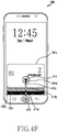
- FIG. 1 illustrates an example of a mobile payment screen 191 of a running mobile payment application displayed on the touch screen 190.
- the mobile payment screen 191 displays a mobile card 191a used for payment.
- One mobile card 191a or a plurality of mobile cards 191a to 191c may be displayed.
- a user may pay by bringing the mobile card 191a displayed on the portable apparatus 100 into either contact or non-contact with a point of sale (POS) device 200.
- POS point of sale
- the POS device 200 may recognize a magnetic card with a magnetic stripe or an integrated chip (IC) card with an embedded microchip.
- the POS device 200 may recognize a magnetic mobile card with no magnetic stripe. Further, the POS device 200 may recognize a mobile card using short-range communications (for example, Bluetooth, Bluetooth low energy (BLE), infrared data association (IrDA,), ultra wideband (UWB), magnetic secure transmission (MST), and/or near field communication (NFC)).
- short-range communications for example, Bluetooth, Bluetooth low energy (BLE), infrared data association (IrDA,), ultra wideband (UWB), magnetic secure transmission (MST), and/or near field communication (NFC)
- the touch screen 190 of the portable apparatus 100 may display one or more home screens (not shown).
- the home screens (not shown) may display a shortcut icon (not shown) corresponding to an application to be selected via a touch (for example, including hovering), a weather widget (not shown), a clock widget (not shown), and the like.
- a status bar which displays a status of the portable apparatus 100, such as a battery charging status, received signal strength, and current time, may be displayed above the home screens (not shown). Further, the home screens (not shown) of the portable apparatus 100 may be positioned below the status bar (not shown) or may be displayed alone without the status bar (not shown) being displayed.
- a first camera 151, one or a plurality of speakers 163, a proximity sensor 171, and an illuminance sensor 172 may be positioned on an upper portion of the front side 100a of the portable apparatus 100.
- a second camera 152 and a flash 153 may be positioned on a rear side (not shown) of the portable apparatus 100.
- buttons 161a-161e, referred to generally as '161' may be provided not only as a physical button (for example, the home button 161a, a power/lock button 161d, volume buttons 161e, or the like) but also as a touch button (for example, the home button 161a, the recent app button 161b, and the back button 161c). Further, the buttons 161 may be displayed along with a text or an icon on the touch screen 190.
- the power/lock button 161d and the volume buttons 161e may be positioned on a lateral side 100b of the portable apparatus 100.
- the lateral side 100b of the portable apparatus 100 may connect the front side 100a and the rear side (not shown) of the portable apparatus 100.
- the lateral side 100b of the portable apparatus 100 may include a left lateral side, a right lateral side, a top side, and a bottom side.
- One or a plurality of microphones 162 may be positioned on the top side, the lateral side 100b, and/or the bottom side of the portable apparatus 100.
- a connector 165 (see FIG. 2 ) and/or the speaker 163 may be positioned on the top side, the lateral side 100b, and/or the bottom side of the portable apparatus 100.
- An insertion hole (not shown) into which an input pen 167 (see FIG. 2 ) with a button (not shown) is inserted may be positioned on the top side or bottom side of the portable apparatus 100. The input pen 167 (see FIG. 2 ) may be kept in the portable apparatus 100 through the insertion hole (not shown) and be drawn out of the portable apparatus 100 for use.
- FIG. 2 is a schematic block diagram illustrating a portable apparatus according to an embodiment of the present disclosure.
- the portable apparatus 100 may be connected to a different apparatus (for example, a wearable apparatus or a server) via a cable or wirelessly using a mobile communication unit 120, a sub-communication unit 130, and a connector 165.
- the portable apparatus 100 may include a mobile phone (not shown), a smartphone (not shown), a tablet device (not shown), an Moving Picture Experts Group (MPEG-1 or MPEG-2) audio layer 3 (MP3) player (not shown), a video player (not shown), an electronic whiteboard (not shown), a monitor (not shown), an electronic device with a display (for example, a refrigerator, a washing machine, an air conditioner, or the like), a display apparatus (not shown), or the like.
- MPEG-1 or MPEG-2 Moving Picture Experts Group
- MP3 MP3
- MP3 Moving Picture Experts Group
- MP3 Motion Picture Experts Group
- video player not shown
- an electronic whiteboard not shown
- a monitor not shown
- an electronic device with a display for example, a refrigerator, a washing
- the display apparatus may be provided as an analog television (TV), a digital TV, a three-dimensional (3D) TV, a smart TV, an light emitting diode (LED) TV, an organic LED (OLED) TV, a plasma TV, a curved TV with a fixed-curvature screen, a flexible TV with a fixed-curvature screen, a bended TV with a fixed-curvature screen, and/or a curvature-variable TV with a screen curvature changing based on a received user input.
- TV analog television
- digital TV digital TV
- 3D three-dimensional
- a smart TV an light emitting diode
- LED light emitting diode
- OLED organic LED
- a plasma TV a curved TV with a fixed-curvature screen
- a flexible TV with a fixed-curvature screen a bended TV with a fixed-curvature screen
- a curvature-variable TV with a screen curvature changing based on a received
- the portable apparatus 100 may transmit data (content, payment information, or the like) to the outside or receive data from the outside through the communication unit 120 or 130 using the touch screen 190.
- the portable apparatus 100 may transmit data (content, payment information, or the like) to the outside or receive data from the outside through the communication unit 120 or 130 using the input pen 167 and the touch screen 190.
- the portable apparatus 100 may transmit data (content, payment information, or the like) to the outside or receive data from the outside corresponding to an interaction (for example, a touch or touch gesture) input through the touch screen 190.
- the portable apparatus 100 may transmit data (content, payment information, or the like) to the outside or receive data from the outside through the communication unit 120 or 130 using a display (for example, an example having only a display panel without a touch panel, not shown).
- the portable apparatus 100 includes a controller 110, the mobile communication unit 120, the sub-communication unit 130, a multimedia unit 140, a camera 150, a global positioning system (GPS) 155, an input/output unit 160, a sensor unit 170, a storage unit 175, and a power supply 180. Further, the portable apparatus 100 includes the touch screen 190 and a touch screen controller 195.
- a controller 110 the mobile communication unit 120, the sub-communication unit 130, a multimedia unit 140, a camera 150, a global positioning system (GPS) 155, an input/output unit 160, a sensor unit 170, a storage unit 175, and a power supply 180.
- GPS global positioning system
- the portable apparatus 100 includes the touch screen 190 and a touch screen controller 195.
- the controller 110 may include a processor 111, a read-only memory (ROM) 112 that stores a control program to control the portable apparatus 100, and a random-access memory (RAM) 113 that stores signals or data input from the outside of the portable apparatus 100 or is used as a storage area for various operations performed via the portable apparatus 100.
- ROM read-only memory
- RAM random-access memory
- the controller 110 functions to control overall operations of the portable apparatus 100 and signal flow between internal components 120 to 195 of the portable apparatus 100, and functions to process data.
- the controller 110 controls the supply of power to the internal components 120 to 195 using the power supply 180.
- the controller 110 may operate a sensor of the sensor unit 170, or may run an OS or an application stored in the storage unit 175.
- the processor 111 may include a graphic processing unit (GPU, not shown) for graphic processing.
- the processor 111 may be provided in the form of a system on chip (SOC) including a core (not shown) and a GPU (not shown).
- SOC system on chip
- the processor 111 may include a single core, a dual core, a triple core, a quad core, and a core of a multiple thereof. Further, the processor 111, the ROM 112, and the RAM 113 may be connected to each other via a bus.
- the controller 110 may control the mobile communication unit 120, the sub-communication unit 130, the multimedia unit 140, the camera 150, the GPS 155, the input/output unit 160, the sensor unit 170, the storage unit 175, the power supply 180, the touch screen 190, and the touch screen controller 195.
- the controller 110 controls a button (for example, the home button 161a) to receive a first input and the touch screen 190, which is positioned above the button and displays a first screen, and controls to change the first screen to a mobile payment screen corresponding to a continuous movement of a first touch, which is connected from the received first input and is detected on the touch screen 190.
- a button for example, the home button 161a
- a fingerprint sensor 173 is installed in the button, and the controller 110 may authenticate a user with a user fingerprint received through the fingerprint sensor 173.
- the controller 110 may control to detect the first input and the first touch as a single touch gesture.
- the controller 110 may detect the first input and the first touch as the single touch gesture using one of a time interval between the first input and the first touch and an area between the first input and the first touch.
- the controller 110 may control to gradually display a payment mobile card from one side of the touch screen 190 corresponding to the authentication with the fingerprint and the continuous movement of the first touch.
- the touch screen 190 includes a bezel touch area for receiving the first touch and a swipe area for receiving the continuous movement of the first touch.
- the controller 110 may control to display the mobile payment card on the touch screen 190.
- the controller 110 may control to display the mobile payment screen.
- the controller 110 may control to provide a feedback corresponding to the continuous movement of the first touch, and the feedback may include at least one of a visual feedback, an audio feedback, and a haptic feedback.
- the controller 110 may detect the continuous movement of the first touch as one of a straight line and a curve.
- the controller 110 controls the touch screen 190 to display a first screen and a button (for example, the home button 161a) that is positioned below the touch screen 190 and receives a first touch, and controls to change the first screen to a mobile payment screen corresponding to a continuous movement of a first input detected on the touch screen 190 and the first touch.
- a button for example, the home button 161a
- the fingerprint sensor 173 is installed in the button, and the controller 110 may authenticate a user with a user fingerprint received through the fingerprint sensor 173.
- the controller 110 may control to gradually display a mobile payment card from one side of the touch screen 190 corresponding to the continuous movement of the first input and the authentication with the fingerprint.
- the touch screen 190 includes a swipe area for receiving the continuous movement of the first input and a bezel touch area for receiving a final position of the continuous movement of the first input.
- the controller 110 may control to display the payment mobile card on the touch screen 190.
- controller includes the processor 111, the ROM 112, and the RAM 113.
- the mobile communication unit 120 may connect to a different apparatus (for example, another portable apparatus, a wearable apparatus, or a server) through a mobile communication network using one or more antennas according to control by the controller 110.
- the mobile communication unit 120 may receive data (or content) from the different apparatus according to control by the controller 110.
- the received data (or content) may be stored in the storage unit 175 according to control by the controller 110.
- the mobile communication unit 120 may transmit/receive a radio signal for a voice call, a video call, a text message, short message service (SMS), a multimedia message (MMS), and data communications to/from a mobile phone with a phone number for connection (not shown), a smartphone (not shown), a tablet personal computer (PC), or other portable apparatuses (not shown).
- the sub-communication unit 130 may connect to a different apparatus (for example, another portable apparatus, a wearable apparatus, or a server) through a wireless local area network (WLAN) communication unit 131 and/or a short-range communication unit 132 according to control by the controller 110.
- the sub-communication unit 130 may receive data (or content) from the different apparatus according to control by the controller 110.
- the received data (or content) may be stored in the storage unit 175 according to control by the controller 110.
- the WLAN communication unit 131 may be connected with an access point (AP) wirelessly in a place where the AP is installed according to control by the controller 110.
- the WLAN communication unit 131 may include, for example, WiFi.
- the WLAN communication unit 131 supports Institute of Electrical and Electronics Engineers (IEEE) WLAN standards (IEEE 802.11x).
- IEEE Institute of Electrical and Electronics Engineers
- the short-range communication unit 132 enables wireless short-range communications between the portable apparatus 100 and an external apparatus without an AP according to control by the controller 110.
- Short-range communications may include Bluetooth, BLE, IrDA, UWB, MST, and/or NFC.
- MST may generate a magnetic signal corresponding to payment information (for example, mobile card information or the like) through a coil antenna (not shown) and may transmit the magnetic signal to the POS device 200.
- payment information for example, mobile card information or the like
- a coil antenna not shown
- the controller 110 may generate a pulse corresponding to transmission data (for example, payment information or the like) through MST, and the generated pulse may generate a magnetic signal.
- the portable apparatus 100 may transmit the generated magnetic signal to the POS device 200.
- an MST coil antenna (not shown) may have an inductance of 10 to 20 ⁇ H.
- the portable apparatus 100 may include one of the mobile communication unit 120, the WLAN communication unit 131, and the short-range communication unit 132 or a combination of the mobile communication unit 120, the WLAN communication unit 131, and the short-range communication unit 132 according to functions and/or performance.
- the portable apparatus 100 may connect to various external accessories (for example, a wireless speaker, a wireless headset, or the like) using one of the mobile communication unit 120 and the sub-communication unit 130.
- the term “communication unit” includes the mobile communication unit 120 and/or the sub-communication unit 130.
- the multimedia unit 140 may receive an external broadcast and may play an audio and/or video according to control by the controller 110.
- the multimedia unit 140 may include a broadcast communication unit 141, an audio player 142, or a video player 143.
- the broadcast communication unit 141 may receive a broadcast signal (for example, a TV broadcast signal, a radio broadcast signal, or a data broadcast signal) and additional broadcast information (for example, an electronic program guide (EPG) or an electronic service guide (ESG)), which are sent from an external broadcasting station, through an antenna (not shown) according to control by the controller 110. Further, the controller 110 may control to play the received broadcast signal and additional broadcast information using the touch screen 190, a video codec (not shown), and an audio codec (not shown).
- a broadcast signal for example, a TV broadcast signal, a radio broadcast signal, or a data broadcast signal
- additional broadcast information for example, an electronic program guide (EPG) or an electronic service guide (ESG)
- EPG electronic program guide
- ESG electronic service guide
- the audio player 142 may play an audio source (for example, an audio file identified by a file extension of mp3, wma, ogg, or wav) that is previously stored in the storage unit 175 of the portable apparatus 100 or that is received from the outside using the audio codec according to control by the controller 110.
- an audio source for example, an audio file identified by a file extension of mp3, wma, ogg, or wav
- the audio player 142 may play an audio feedback corresponding to a change to a mobile payment screen according to a touch gesture input through the touch screen 190.
- the audio player 142 may play, through the audio codec, an audio feedback (for example, an output from an audio source stored in the storage unit 175) corresponding to a change to a mobile payment screen according to a touch gesture input through the touch screen 190 according to control by the controller 110.
- the audio player 142 may play, through the audio codec, an audio feedback (for example, an output from an audio source stored in the storage unit 175) corresponding to a touch detected through the touch screen 190 or a continuous movement of the touch according to control by the controller 110.
- an audio feedback for example, an output from an audio source stored in the storage unit 175
- the video player 143 may play a digital video source (for example, a video file identified by a file extension of mpeg, mpg, mp4, avi, mov, or mkv) that is previously stored in the storage unit 175 of the portable apparatus 100 or that is received from the outside using the video codec according to control by the controller 110.
- a multimedia application installable on the portable apparatus 100 may play the audio source or video source using the audio codec and/or video codec. Further, a multimedia application installable on the portable apparatus 100 may play the video source using a hardware codec (not shown) and/or software codec (not shown).
- the video player 143 may play a visual feedback corresponding to a change to a mobile payment screen according to a touch gesture input through the touch screen 190.
- the video player 143 may play, through the video codec, a visual feedback (for example, an output from a video source stored in the storage unit 175) corresponding to a change to a mobile payment screen according to a touch gesture input through the touch screen 190 according to control by the controller 110.
- the multimedia unit 140 may include the audio player 142 and the video player 143, excluding the broadcast communication unit 141, depending on the performance or structure of the portable apparatus 100. Further, the controller 110 may also be configured to include the audio player 142 or the video player 143 of the multimedia unit 140.
- audio codec may include one or more pieces of audio codec.
- video codec may include one or more pieces of video codec.
- the camera 150 may take a still image or a video according to control by the controller 110.
- the camera 150 may include at least one of the first camera 151 on the front side 100a and the second camera 152 in FIG. 2 on the rear side (not shown).
- the camera 150 may include one or both of the first camera 151 and the second camera 152.
- the first camera 151 or the second camera 152 may include an auxiliary light source (for example, the flash 153) which supplies a necessary amount of light for taking images.
- the camera 150 may be configured to include the first camera 151 on the front side 100a and to further include an additional camera (for example, a third camera (not shown)) adjacent to the first camera 151.
- a space between the third camera (not shown) and the first camera 151 may be provided to be greater than 30 mm and to be less than 80 mm.
- the controller 110 may take a 3D still image or a 3D video using the first camera 151 and the third camera (not shown).
- the camera 150 may be configured to include the second camera 152 on the rear side and to further include an additional camera (for example, a fourth camera (not shown)) adjacent to the second camera 152.
- a space between the fourth camera (not shown) and the second camera 152 may be provided to be greater than 30 mm and be less than 80 mm.
- the controller 110 may take a 3D still image or a 3D video using the second camera 152 and the fourth camera (not shown).
- the cameras 151 and 152 may take wide-angle images, telephotos, and close-up images using an additional lens (not shown) that is detachable from a separate adaptor (not shown).
- the GPS 155 periodically receives a signal (for example, GPS satellite orbit information, satellite time information, and a navigation message) from a plurality of GPS satellites (not shown) on the Earth's orbit.
- a signal for example, GPS satellite orbit information, satellite time information, and a navigation message
- the portable apparatus 100 may calculate positions of the plurality of GPS satellites (not shown) and the portable apparatus 100 using signals received from the plurality of GPS satellites (not shown) and may calculate a distance using a transmission/reception time difference.
- a position, time, or moving speed of the portable apparatus 100 may be calculated by triangulation.
- An additional GPS satellite may be needed for orbit correction or time correction.
- the portable apparatus 100 may also calculate a position, time, or moving speed of the portable apparatus 100.
- the portable apparatus 100 may detect the position or moving speed of the portable apparatus 100 using a wireless AP (not shown). Detecting the position of the portable apparatus 100 indoors may be performed using a cell identification (cell-ID) method using an ID of the wireless AP, an enhanced cell-ID method using the ID of the wireless AP and received signal strength (RSS), or an angle of arrival (AoA) method using an angle at which the portable apparatus 100 receives a signal transmitted from the AP.
- cell-ID cell identification
- RSS received signal strength
- AoA angle of arrival
- the portable apparatus 100 may detect the position or moving speed of the portable apparatus 100 positioned indoors using a radio beacon (not shown). It would be easily understood by a person skilled in the art that various methods, in addition to the foregoing methods, may be used to detect the indoor position of the portable apparatus 100.
- the input/output unit 160 may include at least one of one or more buttons 161, one or more microphones 162, one or more speakers 163, one or more vibration motors 164, a connector 165, a keypad 166, and an input pen 167.
- the buttons 161 include a home button 161a, a recent app button 161b, and/or a back button 161c positioned on a lower portion of the front side 100a of the portable apparatus 100.
- the buttons 161 may include a power/lock button 161d and at least one volume button 161e positioned on a lateral side 100b of the portable apparatus 100.
- the buttons 161 of the portable apparatus 100 may include the home button 161a, the power/lock button 161d, and the volume button 161e only.
- the buttons 161 may be provided not only as a physical button but also as a touch button. Further, the buttons 161 of the portable apparatus 100 may be displayed in the form of a text, an image, or an icon on the touch screen 190.
- the controller 110 may receive a signal generated from the buttons 161 corresponding to a user input.
- the controller 110 may detect the user input using the received signal (for example, a push of the buttons 161 or a touch of the buttons 161).
- the controller 110 may change a screen of the touch screen corresponding to the user input or may receive fingerprint information corresponding to a user fingerprint.
- Shapes, positions, functions, and names of the buttons 161 illustrated in FIGS. 1 , 4A , 4B , 5A-5C , 5E , and 5F are examples for description. It would be easily understood by a person skilled in the art that the shapes, positions, functions, and names of the buttons 161 may be altered, changed, or modified, without being limited thereto.
- the microphone 162 receives a voice or sound from the outside to generate an electrical signal according to control by the controller 110.
- the electrical signal generated from the microphone 162 may be converted in the audio codec and be stored in the storage unit 175 or output through the speaker 163 according to control by the controller 110.
- One or more microphones 162 may be positioned on the front side 100a, the lateral side 100b, and/or the rear side of the portable apparatus 100. Alternatively, one or more microphones 162 may be positioned only on the lateral side 100b of the portable apparatus 100.
- the speaker 163 may output sounds corresponding to various signals (for example, a radio signal, a broadcast signal, an audio source, a video file, photographing, or the like), decoded by the audio codec, according to control by the controller 110.
- signals for example, a radio signal, a broadcast signal, an audio source, a video file, photographing, or the like
- the speaker 163 may output a sound corresponding to a function performed via the portable apparatus 100 (for example, a touch operation sound corresponding to a phone number input or a photographing operation sound).
- One or a plurality of speakers 163 may be positioned on the front side 100a, the lateral side 100b, and/or the rear side of the portable apparatus 100.
- One or a plurality of speakers may be positioned on the front side 100a of the portable apparatus 100.
- One speaker may be positioned on each of the front side 100a and the rear side of the portable apparatus 100.
- One speaker 163 may be positioned on the front side 100a of the portable apparatus 100 and a plurality of speakers (not shown) may be positioned on the rear side.
- a plurality of speakers may be positioned on the lateral side 100b of the portable apparatus 100.
- the portable apparatus 100 which has an additional speaker (not shown) positioned on the lateral side 100b of the portable apparatus 100, may provide a user with a sound effect that is distinguished from one provided from a different portable apparatus (not shown) having speakers positioned on the front side 100a and the rear side.
- the speaker 163 may output an audio feedback corresponding to content that is changed corresponding to a change to a mobile payment screen.
- the speaker 163 may output an audio feedback corresponding to content that is changed corresponding to a change to a mobile payment screen according to control by the controller 110.
- the vibration motor 164 may convert an electrical signal into mechanical vibrations according to control by the controller 110.
- the vibration motor 164 may include a linear vibration motor, a bar-type vibration motor, a coin-type vibration motor, or a piezoelectric element vibration motor.
- the vibration motor 164 may operate in the portable apparatus 100 in a vibration mode according to control by the controller 110.
- One or more vibration motors 164 may be positioned in the portable apparatus 100. Further, the vibration motor 164 may vibrate the entire portable apparatus 100 or may locally vibrate only a portion of the portable apparatus 100.
- the vibration motor 164 may output a haptic feedback corresponding to a change to a mobile payment screen according to a touch gesture input through the touch screen 190.
- the vibration motor 164 may output a haptic feedback corresponding to a change to a mobile payment screen according to a touch gesture input through the touch screen 190 according to control by the controller 110.
- the vibration motor 164 may provide various haptic feedbacks (for example, intensities of vibrations and periods of vibration times) previously stored or received from the outside based on a control command from the controller 110.
- the connector 165 may be used as an interface to connect the portable apparatus 100 and an external apparatus (not shown) or power source (not shown).
- the portable apparatus 100 may transmit data (or content) stored in the storage unit 175 to the outside or receive data (or content) from the outside through a wire-based cable connected to the connector 165 according to control by the controller 110.
- the portable apparatus 100 may be supplied with power from the power source (not shown) or may charge a battery (not shown) through the wire-based cable connected to the connector 165 according to control by the controller 110. Further, the portable apparatus 100 may be connected with an accessory (for example, a speaker (not shown) and a keyboard dock (not shown)) through the connector 165.
- the keypad 166 may receive a key input from the user to control the portable apparatus 100.
- the keypad 166 includes a physical keypad (not shown) formed on the front side 100a of the portable apparatus 100, a virtual keypad (not shown) displayed in the touch screen 190, and a physical keypad (not shown) connectable wirelessly or via a cable. It would be easily understood by a person skilled in the art that the physical keypad (not shown) formed on the front view 100a of the portable apparatus 100 may be excluded depending on performance or a structure of the portable apparatus 100.
- the input pen 167 may touch (or select), by the user, an object (for example, a menu, a text, an image, a video, a figure, an icon, and a shortcut icon) displayed (formed) on the touch screen 190 of the portable apparatus 100 or on a screen of a write/draw application (a menu screen, a notepad screen, a calendar screen, and the like).
- an object for example, a menu, a text, an image, a video, a figure, an icon, and a shortcut icon displayed (formed) on the touch screen 190 of the portable apparatus 100 or on a screen of a write/draw application (a menu screen, a notepad screen, a calendar screen, and the like).
- the input pen 167 may touch or select, by the user, content (for example, a text file, an image file, an audio file, a video file, or a webpage) displayed on the touch screen 190 of the portable apparatus 100 or on the screen of the write/draw application (the menu screen, the notepad screen, the calendar screen, and the like).
- content for example, a text file, an image file, an audio file, a video file, or a webpage
- the input pen 167 may handwrite, draw, paint or sketch, by the user, on a screen of a write application (for example, a memo screen) or a draw application (for example, a canvas screen) displayed on the touch screen 190 of the portable apparatus 100.
- a write application for example, a memo screen
- a draw application for example, a canvas screen
- the input pen 167 may input letters by touching a capacitive touch screen, a resistive touch screen, or an electromagnetic resonance (EMR) touch screen (including edge touch screens) or using a displayed virtual keypad.
- the input pen 167 may include a stylus pen or a haptic pen (not shown), which has a vibrating embedded vibration element (for example, an actuator or vibration motor). Further, the input pen 167 may operate (for example, vibrate) the vibration element corresponding to not only control information received from the portable apparatus 100 but also sensing information detected by a sensor embedded in the input pen 167 (for example, an acceleration sensor, not shown).
- the controller 110 may run the set write/draw application and display the screen (not shown) of the write/draw application on the touch screen 190.
- the input pen 167 may include a user's finger (for example, a thumb).
- a writing or drawing may be input using a user's finger via the application displayed on a capacitive touch screen (including a capacitive edge touch screen) or a resistive touch screen (including a resistive edge touch screen).
- the controller 110 may detect a touch by one of the fingers, including a thumb, using the touch screen 190 or touch screen controller 195.
- a shape of the insertion hole (not shown) of the portable apparatus 100 and/or a shape (for example, a circular cross section or polygonal cross section) or structure (for example, including a battery (not shown)) of the input pen 167 may be changed depending on performance or a structure of the portable apparatus 100.
- the sensor unit 170 may detect a state of the portable apparatus 100 and/or an ambient state of the portable apparatus 100.
- the sensor unit 170 may include one or a plurality of sensors.
- the sensor unit 170 may include the proximity sensor 171 to detect whether the user approaches the portable apparatus 100, the illuminance sensor 172 to detect the amount of ambient light of the portable apparatus 100, or the fingerprint sensor 173 to detect a fingerprint of the user using the portable apparatus 100.
- the fingerprint sensor 173 may be positioned on the front side 100a of the portable apparatus 100.
- the fingerprint sensor 173 may be positioned below the touch screen 190 of the portable apparatus 100.
- the fingerprint sensor 173 may be positioned in a bezel below the touch screen 190.
- the fingerprint sensor 173 may be positioned close to (for example, 1 mm or greater distant from) the touch screen 190 of the portable apparatus 100.
- the fingerprint sensor 173 may be installed in a button (for example, the home button 161a) of the portable apparatus 100.
- the fingerprint sensor 173 may be installed in the touch screen 190 of the portable apparatus 100.
- the touch screen 190 may be a fingerprint recognition-integrated touch screen (or a fingerprint recognition-integrated capacitive touch screen, not shown).
- the fingerprint sensor 173 may include an optical fingerprint sensor (not shown) to capture a fingerprint image, an ultrasonic fingerprint sensor (not shown), a capacitive fingerprint sensor (not shown), a semiconductor fingerprint sensor (not shown) to detect electrical conductivity, a heat detection fingerprint sensor (heart rate sensor, not shown), and combinations of the foregoing fingerprint sensors. It would be easily understood by a person skilled in the art that the fingerprint sensor 173 may be provided as various fingerprint sensors in addition to the foregoing fingerprint sensors.
- the sensor unit 170 may include an acceleration sensor (not shown) to detect three-axes (for example, x-axis, y-axis, and z-axis) accelerations applied to the portable apparatus 100, a gravity sensor to detect a direction of exerted gravity, or an altimeter, which measures atmospheric pressure to detect an altitude.
- an acceleration sensor not shown
- three-axes for example, x-axis, y-axis, and z-axis
- gravity sensor to detect a direction of exerted gravity
- an altimeter which measures atmospheric pressure to detect an altitude.
- the sensor unit 170 may measure motion acceleration and gravitational acceleration of the portable apparatus 100. When the portable apparatus 100 remains stationary, the sensor unit 170 may measure the gravitational acceleration only.
- the sensor unit 170 may further include a heart rate sensor (not shown) to detect heart rate of the user.
- At least one sensor included in the sensor unit 170 detects a state of the portable apparatus 100, and generates and transmits an electrical signal corresponding to a detection to the controller 110. It would be easily understood by a person skilled in the art that sensors included in the sensor unit 170 may be added, changed, or deleted depending on performance of the portable apparatus 100.
- the storage unit 175 may store signals or data input/output corresponding to operations of the mobile communication unit 120, the sub-communication unit 130, the multimedia unit 140, the camera 150, the GPS 155, the input/output unit 160, the sensor unit 170, and the touch screen 190 according to control by the controller 110.
- the storage unit 175 may store GUIs associated with control programs to control the portable apparatus 100 or the controller 110 and applications provided from a manufacturer or downloaded from the outside, images for providing the GUIs, user information, documents, databases, or relevant data.
- the storage unit 175 may store portable apparatus information including resolution information and size information on the touch screen 190 and server information on a server (not shown) that is connectable with the portable apparatus 100.
- the storage unit 175 may store size and resolution information on an edge touch screen (not shown). Further, the storage unit 175 may store curvature information on the edge touch screen (not shown).
- the storage unit 175 may store first input information corresponding to a first input 410 (see FIGS. 4B to 4F ) and eleventh input information corresponding to an eleventh input 451 (see FIGS. 5D to 5F ).
- the storage unit 175 may store first touch position information corresponding to a first touch 411 (see FIGS. 4C to 4F ) and eleventh touch position information corresponding to an eleventh touch 450 (see FIGS. 5B to 5E ).
- the storage unit 175 may store position information on a plurality of touches (for example, at an initial position, an intermediate position, a final position, or the like) corresponding to a continuous movement of the first touch 411 and position information on a plurality of touches (for example, at an initial position, an intermediate position, a final position, or the like) corresponding to a continuous movement of the eleventh touch 450.
- the storage unit 175 may store fingerprint recognition area information on each of fingerprint recognition areas d1 and d13 (see FIGS. 4D and 5E ), bezel touch area information on each of bezel touch areas d2 and d12 (see FIGS. 4D and 5E ), and swipe region information on each of swipe areas d3 and d11 (see FIGS. 4D and 5E ).
- the storage unit 175 may store time interval T1 information and setting area A1 information.
- the storage unit 175 may store a mobile payment application (for example, Samsung Pay or the like) using the portable apparatus 100 and/or data (for example, mobile payment information or the like).
- a mobile payment application for example, Samsung Pay or the like
- data for example, mobile payment information or the like
- the storage unit 175 may store one or a plurality of pieces of registered mobile card information (for example, a card number, an owner's name, an expiration date, or the like). Further, the storage unit 175 may store payment information on a registered mobile card (for example, mobile card information, a payment time, a payment place, or the like).
- the storage unit 175 may store a user-recognizable visual feedback (for example, a video source or the like) output on the touch screen 190 corresponding to user authentication with a fingerprint, passing through the swipe areas d1 and d11, and/or display of a mobile payment screen, a user-recognizable audio feedback (for example, a sound source or the like) output from the speaker 163, and a user-recognizable haptic feedback (for example, a haptic pattern or the like) output from the vibration motor 164.
- a user-recognizable visual feedback for example, a video source or the like
- a user-recognizable audio feedback for example, a sound source or the like
- haptic feedback for example, a haptic pattern or the like
- the storage unit 175 may store a feedback providing time (for example, 500 ms) for a feedback provided for the user.
- the storage unit 175 may store an application and/or data corresponding to a user fingerprint recognition function through the fingerprint sensor 173 of the portable apparatus 100.
- the storage unit 175 may store one or a plurality of applications corresponding to fingerprint scanning through the fingerprint sensor 173 and image processing and an input/output of the scanned fingerprint.
- the storage unit 175 may store data processed via one or a plurality of applications (for example, a previously registered user fingerprint, characteristics of the user fingerprint, or the like).
- the term “storage unit” includes the storage unit 175, the ROM 112 and RAM 113 in the controller 110, or a memory card (not shown, for example, a micro SD or a memory stick) mounted on the portable apparatus 100.
- the storage unit 175 may include a nonvolatile memory, a volatile memory, a hard disk drive (HDD), or a solid state drive (SSD).
- the power supply 180 may supply power to the components 120 to 195 positioned in the portable apparatus 100 according to control by the controller 110.
- the power supply 180 may supply the components of the portable apparatus 100 with power input from an external power source (not shown) through a wire-based cable (not shown) connected to the connector 165 according to control by the controller 110. Further, the power supply 180 may supply power to one or more batteries (not shown) to charge the batteries according to control by the controller 110.
- the one, two, or more batteries (not shown) may be positioned between the touch screen 190 positioned on the front side 100a and the rear side (not shown).
- the power supply 180 may wirelessly charge (for example, using a magnetic resonance method, an electromagnetic wave method, or a magnetic induction method) the one, two, or more batteries (not shown) using a separate coil (not shown) according to control by the controller 110.
- the touch screen 190 includes an edge touch panel (not shown) to receive a touch input and an edge display panel (not shown) to display a screen.
- the touch screen 190 may provide the user with GUIs corresponding to various services (for example, a voice call, a video call, data transmission, broadcast reception, photographing, video watching, or application execution).
- the touch screen 190 transmits an analog signal corresponding to a single touch or multi-touch input through a home screen 191 or a GUI to the touch screen controller 195.
- the touch screen 190 may receive a single touch or a multi-touch through a user body part (for example, fingers including a thumb) or the input pen 167.
- the touch screen 190 may be an integrated edge touch screen with both lateral sides curved. Alternatively, the touch screen 190 may be an integrated edge touch screen with one lateral side curved.
- the edge touch screen may have one of a single curvature or a multi-curvature.
- the single curvature may be 13 R or greater and 5 R or smaller.
- One of one lateral side and both lateral sides of the portable apparatus 100 including an edge touch screen with a single curvature may have a semicircular or oval cross section (not shown).
- a first curvature of the multi-curvature may be 12 R or 13 R.
- the first curvature may be 13 R or greater and 5 R or smaller.
- a remaining second curvature of the multi-curvature may be 6.5 R or 6.9 R.
- the second curvature may be 8 R or greater and 4 R or smaller.
- One of one lateral side and both lateral sides of the portable apparatus 100 including an edge touch screen with a multi-curvature may have a semicircular or oval cross section (not shown).
- the single curvature value and/or the multi-curvature value in an embodiment of the present disclosure are examples only, without being limited thereto. It would be easily understood by a person skilled in the art that a single curvature value and/or multi-curvature value may be changed.
- the display panel includes a plurality of pixels and displays an image through the pixels.
- the edge display panel may include a liquid crystal display (LCD), a LED, or an OLED.
- the edge display panel may display various images and a plurality of objects according to various operation states of the portable apparatus 100 and the execution of an application or service.
- a touch includes not only a contact between the touch screen 190 and a user body part or the input pen 167 but a non-contract therebetween.
- the non-contact may include a hovering with a space between the touch screen 190 and a user body part or the input pen 167 being 50 mm or shorter. It would be easily understood by a person skilled in the art that a non-contact space that is detectable through the touch screen 190 may be changed depending on the performance or structure of the portable apparatus 100.
- the touch screen 190 may be provided as a resistive type, a capacitive type, an infrared type, or an ultrasonic wave (acoustic wave) type.
- the touch screen 190 may include an EMR type.
- the EMR edge touch screen further includes a separate EMR edge touch panel (not shown) to receive an input with an input pen (not shown) having a resonance circuit that resonates with an EMR loop coil.
- the touch screen 190 may output a visual feedback corresponding to a change to a mobile payment screen according to a touch gesture input through the touch screen 190.
- the touch screen 190 may display a visual feedback corresponding to changed content corresponding to a change to a mobile payment screen according to a touch gesture input through the touch screen 190 according to control by the controller 110.
- the display may include the touch screen 190.
- the touch screen controller 195 converts the analog signal corresponding to the single touch or multi-touch received from the touch screen 190 into a digital signal and transmits the digital signal to the controller 110.
- the controller 110 may calculate an X coordinate and a Y coordinate corresponding to a touch position of the touch input through the touch screen 190 using the digital signal received from the touch screen controller 195.
- the controller 110 may control the touch screen 190 using the digital signal received from the touch screen controller 195.
- the controller 110 may display a shortcut icon displayed corresponding to the input touch on the touch screen 190 to be distinguished from another shortcut icon or may run an application (for example, a call) corresponding to a selected shortcut icon to display an application screen on the touch screen 190.
- the touch screen controller 195 may be provided as a single touch screen controller or a plurality of touch screen controllers.
- the touch screen controller 195 may be included in the controller 110 according to the performance or structure of the portable apparatus 100.
- the touch screen controller 195 may convert an analog signal corresponding to a touch received through the EMR edge touch screen, which is separate from the analog signal corresponding to the single touch or multi-touch received from the touch screen 190, into a digital signal and may transmit the digital signal to the controller 110.
- the controller 110 may calculate an X coordinate and a Y coordinate corresponding to a touch position on the touch screen through the EMR touch screen using the digital signal received from the touch screen controller 195.
- the EMR touch screen may use an EMR touch screen controller (not shown).
- FIGS. 1 and 2 illustrate the portable apparatus 100 including the touch screen only, a plurality of touch screens may be provided. Each touch screen may be positioned in each housing (not shown), and the housings (not shown) may be connected to each other via one or a plurality of hinges (not shown).
- a plurality of touch screens may be disposed up and down or right and left on a front side of one housing (not shown).
- the plurality of touch screens may include one display panel and a plurality of touch panels.
- the plurality of touch screens may include a touch panel corresponding to a plurality of display panels.
- the plurality of touch screens may include a plurality of touch panels corresponding to a plurality of display panels.
- At least one component may be added to the portable apparatus 100 illustrated in FIGS. 1 and 2 , or at least one of the components of the portable apparatus 100 may be changed or deleted depending on performance of the portable apparatus 100.
- FIG. 3A is a schematic flowchart illustrating a screen change method of a portable apparatus according to an embodiment of the present disclosure.
- FIGS. 4A to 4G illustrate examples of a screen on a portable apparatus according to an embodiment of the present disclosure.
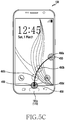
- a first screen is displayed on the touch screen.
- a lock screen 400 as one first screen is displayed on the touch screen 190 according to control by the controller 110.
- the first screen may include not only the lock screen 400 but also a home screen (not shown), a screen of another running application (in-application screen, not shown), or a touch screen off screen (LDC off screen, not shown).
- the first screen includes not only the foregoing screens but also various screens to be displayed on the portable apparatus 100. Also, it would be easily understood by a person skilled in the art that the other running applications may vary.
- the home button 161a is positioned below the touch screen 190 positioned on the front side 100a of the portable apparatus 100. Further, the home button 161a including the fingerprint sensor 173 may be positioned below the touch screen 190 of the portable apparatus 100.
- a user provides the first input 410 through the home button 161a.
- the controller 110 may detect the first input 410 using a push of the home button 161a or the touch of the home button 161a.
- the controller 110 may store first input information corresponding to the detected first input 410 in the storage unit 175.
- the stored first input information may include a touch ID, a touch position, a touch detection time, or the like for record management.
- the controller 110 may supply power to the home button 161a or the home button 161a with the fingerprint sensor 173.
- the controller 110 may always supply power to the home button 161a or the home button 161a with the fingerprint sensor 173.
- the first input 410 by the user may be detected from the home button 161a or from the home button 161a with the fingerprint sensor 173.
- the first input 410 detected from (for example, touching or hovering on) the touch screen 190 may be generated, for example, by a touch with one finger including a thumb or the touchable input pen 167. Further, the first input 410 may be generated with either of the right and left hands.
- a user fingerprint is authenticated.
- the controller 110 may receive fingerprint information corresponding to the user fingerprint using the fingerprint sensor 173 installed in the home button 161a.
- the controller 110 may receive the fingerprint information corresponding to the user fingerprint through a fingerprint recognition area d1 of the fingerprint sensor 173.
- the fingerprint recognition area d1 may be changed corresponding to the size and/or shape of the home button 161a with the fingerprint sensor 173. Further, the fingerprint recognition area d1 may be changed corresponding to the size and/or resolution of the fingerprint sensor 173 installed in the home button 161a.
- the controller 110 may extract a fingerprint characteristic corresponding to the user from the received fingerprint information.
- the controller 110 may compare the extracted fingerprint characteristic with user fingerprint information (for example, including a fingerprint characteristic) previously registered in a fingerprint database in the storage unit 175 to authenticate the user fingerprint.
- the controller 110 may compare the extracted fingerprint characteristic with user fingerprint information (for example, including a fingerprint characteristic) previously registered in an external server (not shown) using the communication unit to authenticate the user fingerprint.
- the controller 110 may use the optical fingerprint sensor (not shown) which irradiates visible light in order to receive a reflected fingerprint image.
- the controller 110 may use the ultrasonic fingerprint sensor (not shown), which irradiates ultrasonic waves to receive a reflected fingerprint image.
- the controller 110 may use the capacitive fingerprint sensor (not shown), which calculates a capacitance difference to obtain fingerprint information.
- the user may swipe from the home button 161a or touch the home button 161a (with the fingerprint sensor 173) for a set time (for example, 1.5 sec or less).
- the controller 110 may compose one-dimensional (1D) fingerprint images, which are received using a sensor electrode linearly disposed with respect to a finger (for example, which is fingerprint-detectable) of the swiping user, into a two-dimensional (2D) fingerprint image. Further, the controller 110 may receive a 2D fingerprint image using a sensor electrode disposed two-dimensionally corresponding to a finger of the user touching the home button 161a with the fingerprint sensor 173.
- operation S302 is repeated.
- operation S304 is performed.
- a first touch is detected in a bezel touch area of the touch screen corresponding to the home button.
- the user provides the first touch 411 in the bezel touch area d2 of the touch screen 190 positioned in an upward direction (for example, the + y-axis direction) from the home button 161a.
- the controller 110 may detect the first touch 411 in the bezel touch area d2 using the touch screen 190 and the touch screen controller 195.
- the controller 110 may calculate a first touch position 411a (for example, an X2 coordinate and a Y2 coordinate) corresponding to the first touch 411 detected in the bezel touch area d2 using an electrical signal received from the touch screen controller 195.
- the controller 110 may detect, in the bezel touch area d2, the first touch 411, which is connected from the first input 410 detected in the fingerprint recognition area d1, and the first touch 411 separate from the first input 410.
- the first touch 411 detected in the bezel touch area d2 may be included in a continuous movement (for example, a swipe as one touch gesture) of the first input 410 detected in the fingerprint recognition area d1.
- the first touch 411 which is separate from the first input 410 which is touch-released at the home button 161a, may be touched on the bezel touch area d2.
- the vertical length of the bezel touch area d2 (for example, in the + y-axis direction based on an edge of the touch screen 190) may be 3 % (for example, 77 pixels) or less of the resolution of the touch screen 190 (for example, 2560 x 1440 pixels). Alternatively, the vertical length of the bezel touch area d2 may be 5 % (for example, 128 pixels) or less of the resolution of the touch screen 190.
- the vertical length of the bezel touch area d2 (for example, in the + y-axis direction based on the edge of the touch screen 190) may be shorter than the vertical length of the fingerprint recognition area d1 (for example, in the + y-axis direction based on the bottom of the fingerprint recognition area d1).
- the vertical length of the bezel touch area d2 may be 50% or less of the vertical length of the fingerprint recognition area d1.
- Detection of the first touch 411 in the bezel touch area d2 may be calculated using a touch detection time of the first input 410 in the fingerprint recognition area d1.
- the controller 110 may detect the first touch 411 in the bezel touch area d2 using a difference (for example, a first time interval T1, 1 sec or less) between a detection time t of the first input 410 in the fingerprint recognition area d1 and a detection time t1 of the first touch 411 in the bezel touch area d2.
- a difference for example, a first time interval T1, 1 sec or less
- the first touch 411 may be detected in the bezel touch area d2 within the first time interval T1. It would be easily understood by a person skilled in the art that the first time interval T1 may be changed.
- Detection of the first touch 411 in the bezel touch area d2 may be calculated using a touch position of the first input 410 in the fingerprint recognition area d1.
- the controller 110 may detect the first touch 411 in the bezel touch area d2 in a semicircular area which extends upwards (for example, in the + y-axis direction) from the touch position of the first input 410 in the fingerprint recognition area d1 and has a radius of 30 mm (for example, a first area A1 in the + y-axis direction) from a contact point with the touch screen 190 (for example, a position in the bezel touch area d2).
- the first touch 411 may be detected in the first area A1 in the bezel touch area d2. It would be easily understood by a person skilled in the art that the first area A1 may be changed.
- the controller 110 may store first touch position information corresponding to the first touch position 411a in the storage unit 175.
- the stored first touch position information may include a touch ID, a touch position, a touch detection time, or touch information (for example, touch pressure, a touch direction, touch duration, or the like) for record management.
- the first touch 411 detected from (for example, touching or hovering on) the touch screen 190 may be generated, for example, by a touch with one finger including a thumb or the touchable input pen 167.
- the first touch 411 may be generated with one of the right and left hands, which is different from one corresponding to the first input 410. For example, when the first input 410 is generated with the left hand, the first touch 411 may be generated with the right hand. On the contrary, when the first input 410 is generated with the right hand, the first touch 411 may be generated with the left hand.
- the controller 110 may detect (or calculate) the continuous movement of the first touch 411 (for example, a plurality of X coordinates and Y coordinates corresponding to a continuous touch) detected in the bezel touch area d2 using the touch screen 190 and the touch screen controller 195. Position information corresponding to the continuous movement of the first touch 411 may be stored in the storage unit 175 according to control by the controller 110.
- the continuous movement of the first touch 411 may refer to a first touch gesture detected in a swipe area d3.
- the swipe area d3 may also be referred to as a swipe up recognition area.
- the continuous movement of the first touch 411 (for example, the movement from the initial position 411a to the end position 411d on the touch screen) may refer to a first touch gesture detected from the bezel touch area d2 to the swipe area d3.
- the continuous movement of the first touch 411 may refer to a first touch gesture detected from the bezel touch area d2 to the swipe area d3 in the upward direction (for example, in the + y-axis direction).
- the continuous movement of the first touch 411 may mean that the first touch 411 is continuously maintained from the bezel touch area d2 to the swipe area d3 in the upward direction (for example, in the + y-axis direction).
- the first touch 411 on the touch screen 190 may be released at the end position 411d of the continuous movement.
- a continuous movement of a touch includes a plurality of touches.
- the four touch positions 411a, 411b, 411c, and 411d illustrated above are one embodiment, and the number of touches in a continuous movement of a touch is not limited thereto. It would be easily understood by a person skilled in the art that the number of touches included in a continuous movement of a touch may vary (for example, corresponding to the resolution of the touch screen 190).
- the continuous movement of the first touch 411 from the bezel touch area d2 to the swipe area d3 in the upward direction may include a drag, a drag and drop, a flick, or a swipe.
- the continuous movement of the first touch 411 may be a straight line or a curve.
- the continuous movement of the first touch 411 with a thumb may be a straight line or a curve.
- a mobile card 191a may gradually emerge from a bottom edge of the touch screen 190 (for example, in the bezel touch area d2).
- the mobile card 191a may gradually be displayed (for example, frame in or fade in) from the bottom edge of the touch screen 190 (for example, in the bezel touch area d2) corresponding to the continuous movement of the first touch 411 passing through the swipe area d3.
- the controller 110 may change the displayed first screen 400 to a different screen (for example, a white background screen, a black background screen, or a grey background screen). Further, when the continuous movement of the first touch 411 passes through the swipe area d3, the controller 100 may change the displayed first screen 400 to a different screen (for example, a single-color background screen or a multi-color background screen).
- the controller 110 may provide the user with a feedback corresponding to the continuous movement of the first touch 411 passing through the swipe area d3.
- the controller 110 may provide one of a visual feedback, an audio feedback, and a haptic feedback. Further, the controller 110 may provide the user with a combination of the visual feedback, the audio feedback, and the haptic feedback.
- the visual feedback may include a visual effect (for example, a separate image or an animation effect, such as fading, applied to a separate image, not shown) corresponding to the continuous movement of the first touch 411 passing through the swipe area d3.
- the controller 110 may display the visual feedback on the touch screen 190.
- the audio feedback may include a sound corresponding to the continuous movement of the first touch 411 passing through the swipe area d3.
- the controller 110 may output the audio feedback through the speaker 163.
- the controller 100 may output the audio feedback through one speaker or a plurality of speakers.
- the haptic feedback may include vibrations corresponding to the continuous movement of the first touch 411 passing through the swipe area d3.
- the controller 110 may output the haptic feedback through the vibration motor 164.
- the controller 110 may output the haptic feedback selectively through one of the vibration motors.
- a feedback providing time (for example, 500 ms) provided for the user may be changed through environment setup (not shown).
- At least one of a plurality of feedbacks (for example, visual, audio, and haptic feedbacks) provided corresponding to the continuous movement of the first touch 411 passing through the swipe area d3 may be selected.
- mobile cards 191a to 191c may gradually be displayed until the continuous movement of the first touch 411 reaches the end position 411d.
- the mobile cards 191a to 191c may move in the upward direction at a constant velocity corresponding to the continuous movement of the first touch 411. Further, the mobile cards 191a to 191c may move in the upward direction at the constant velocity until the continuous movement of the first touch 411 reaches the end position 411d.
- the number of mobile cards 191a to 191c gradually displayed is three in one embodiment and may be changed according to a user setting (for example, card registration).
- the mobile cards 191a to 191c previously registered in the portable apparatus 100 may be displayed to overlap. For example, when the user registers ten mobile cards, the ten mobile cards may be displayed to overlap.
- the mobile card 191a displayed on top may be a default mobile card.
- the controller 110 may display the mobile payment screen 191.
- the controller 110 may align the mobile cards 191a to 191c in a central area of the mobile payment screen 191.
- the controller 110 may bring the mobile cards 191a to 191c into top alignment, bottom alignment, or random alignment.
- the terms “mobile payment screen” and “screen corresponding to mobile payment” may be used to refer to the same meaning.
- the user may select another mobile card 191b, instead of the default mobile card 191a.
- the default mobile card 191a For example, when the user touches (not shown) the default mobile card 191a and swipes (or drag, flick, or the like) across a lateral side (for example, in the +/- x-axis direction) of the touch screen 190, a second mobile card 191b positioned below the default mobile card 191a may be displayed.
- the default mobile card 191a may be positioned below a third mobile card 191c, which has been on the bottom.
- the positions of the default mobile card 191a and the third mobile card 191c may be changed with each other.
- a mobile card other than the default mobile card 191a may be selected (or displayed) not only by the foregoing method including a swipe and/or touch but also by various methods (for example, shaking the portable apparatus 100).
- a mobile card (one of 191a to 191c) may be selected before the first input 410 and the first touch 411.
- the user may select a mobile card (for example, 191b, one of 191a to 191c) first through a mobile payment application.
- the user selects the mobile card 191b and inputs a first input and a continuous movement of a first touch.
- the controller 110 may detect the selection of the mobile card 191b, and the first input and the continuous movement of the first touch 411 using the home button 161a, the touch screen 190, and the touch screen controller 195.
- the controller 110 may display the mobile payment screen 191.
- the user may bring the previously selected mobile card 191b into contact or non-contact with the POS device 200 (see FIG. 1 ) to implement mobile payment.
- the user may bring the top mobile card into contact or non-contact with the POS device 200 (see FIG. 1 ) to implement mobile payment.
- the controller 110 may transmit payment information corresponding to the top mobile card to the POS device 200 (see FIG. 1 ) through a local area network according to a user input.
- the mobile payment screen 191 is displayed and the mobile cards 191a to 191c are aligned, the user may bring the top mobile card into contact or non-contact with the POS device 200 (see FIG. 1 ) to implement mobile payment.
- the controller 110 may provide the user with a feedback corresponding to display of the mobile payment screen 191.
- the controller 110 may provide one of a visual feedback, an audio feedback, and a haptic feedback. Further, the controller 110 may provide the user with a combination of the visual feedback, the audio feedback, and the haptic feedback.
- the feedback provided in operation S306 of FIG. 3A is substantially the same as the feedback provided in operation S305 of FIG. 3A (except for the different operation), and thus a repeated description is omitted herein.
- the fingerprint sensor 173 may not be installed in the home button 161a of the portable apparatus 100.
- operation S303 of FIG. 3A may be excluded from the screen change method of the portable apparatus 100.
- the controller 110 may detect a first input 410 from one of the recent app button 161b and the back button 161c (substantially the same as operation S302 of FIG. 3A ).
- the controller 110 may detect the first touch 411 in the bezel touch area d2 using the touch screen 190 and the touch screen controller 195 (substantially the same as operation S304 of FIG. 3A ).
- the controller 110 may detect the continuous movement of the first touch 411 using the touch screen 190 and the touch screen controller 195 (substantially the same as operation S305 of FIG. 3A ).
- the controller 110 may display the mobile payment screen 191.
- the user may bring the top mobile card into contact or non-contact with the POS device 200 (see FIG. 1 ) to implement mobile payment.
- Display of the mobile payment screen using a touch gesture (for example, a swipe) starting from the home button 161a may be achieved in the portable apparatus 100 having the fingerprint sensor 173 and in the portable apparatus 100 having no fingerprint sensor 173.
- the fingerprint sensor 173 may not be installed in the home button 161a of the portable apparatus 100.
- the touch screen 190 may recognize the user fingerprint.
- the touch screen 190 may be a fingerprint recognition-integrated touch screen (not shown).
- the user fingerprint may be recognized through a set area (for example, a fingerprint recognition area of 30 mm x 30 mm, the size of which varies depending on the size of the touch screen 190, not shown) of the fingerprint recognition-integrated touch screen (not shown).
- the set area (not shown) may be positioned above the home button 161a and may include part of the bezel touch area d2.
- operation S303 of FIG. 3A may be excluded from the screen change method of the portable apparatus 100.
- the controller 110 may detect the first touch 411 in the bezel touch area d2 using the touch screen 190 and the touch screen controller 195. The controller 110 may recognize the user fingerprint using the detected first touch 411.
- the controller 110 may detect the continuous movement of the first touch 411 using the touch screen 190 and the touch screen controller 195.
- the controller 110 may display the mobile payment screen 191.
- the user may bring the top mobile card into contact or non-contact with the POS device 200 (see FIG. 1 ) to implement mobile payment.
- Display of the mobile payment screen using a touch gesture (for example, a swipe) starting from the home button 161a may be achieved in the portable apparatus 100 having the fingerprint sensor 173 and in the portable apparatus 100 having no fingerprint sensor 173.
- the screen change method of the portable apparatus 100 having no fingerprint sensor 173 installed in the home button 161a ends.
- FIG. 3B is a schematic flowchart illustrating a screen change method of a portable apparatus according to an embodiment of the present disclosure.
- FIGS. 5A to 5H illustrate examples of a screen on a portable apparatus according to an embodiment of the present disclosure.
- a first screen is displayed on the touch screen.
- a lock screen 400 as one first screen is displayed on the touch screen 190 according to control by the controller 110.
- the first screen may include not only the lock screen 400 but also a home screen (not shown), a screen of another running application (in-application screen, not shown), or a touch screen off screen (LDC off screen, not shown).
- Display of the first screen in operation S351 of FIG. 3B is substantially the same as operation S301 of FIG. A (except for the different embodiment), and thus a repeated description is omitted herein.
- the user provides the eleventh touch 450 through the touch screen 190.
- the controller 110 may detect the eleventh touch 450 using the touch screen 190 and the touch screen controller 195.
- the controller 110 may calculate an eleventh touch position 450a (for example, X11 and Y11 coordinates) corresponding to the eleventh touch 450 using an electrical signal received from the touch screen controller 195.
- the controller 110 may store eleventh touch position information corresponding to the eleventh touch position 450a in the storage unit 175.
- the stored eleventh touch position information may include a touch ID, a touch position, a touch detection time, or touch information (for example, touch pressure, a touch direction, touch duration, or the like) for record management.
- the controller 110 may detect the eleventh touch 450 in a lateral edge area of the touch screen 190.
- the controller 110 may detect the eleventh touch 450 on one side (for example, one of the right and left sides) based on the center of the touch screen 190 (for example, an intersection point of two virtual lines each connecting two facing corners of the four corners of the touch screen 190).
- the controller 110 may detect the eleventh touch 450 outside a swipe area d11 (see FIG. 5E ) of the touch screen 190. Further, the controller 110 may detect the eleventh touch 450 outside a swipe down recognition area d11 (see FIG. 5E ) of the touch screen 190.
- the eleventh touch 450 detected from (for example, touching or hovering on) the touch screen 190 may be generated, for example, by a touch with one finger including a thumb or the touchable input pen 167.
- the controller 110 may detect (or calculate) the continuous movement of the eleventh touch 450 (for example, a plurality of X coordinates and Y coordinates corresponding to a continuous touch) detected from the touch screen 190 using the touch screen 190 and the touch screen controller 195. Position information corresponding to the continuous movement of the eleventh touch 450 may be stored in the storage unit 175 according to control by the controller 110.
- an end position of the continuous movement is detected.
- the continuous movement of the eleventh touch 450 (for example, a movement from an initial position 450a, through intermediate positions 450b and 450c, to an end position 450d) may refer to an eleventh touch gesture detected from the swipe area d11 to a bezel touch area d12.
- the swipe area d11 may also be referred to as a swipe down recognition area.
- the continuous movement of the eleventh touch 450 (for example, the movement from the initial position 450a to the end position 450d) may refer to an eleventh touch gesture detected in up to the swipe area d11.
- the continuous movement of the eleventh touch 450 may refer to an eleventh touch gesture detected from the swipe area d11 to the bezel touch area d12 in a downward direction (for example, in the - y-axis direction).
- the continuous movement of the eleventh touch 450 may mean that the eleventh touch 450 is continuously maintained from the swipe area d11 to the bezel touch area d12 in the downward direction (for example, in the - y-axis direction).
- the eleventh touch 450 on the touch screen 190 may be released at the end position 450d of the continuous movement.
- the continuous movement of the eleventh touch 450 may pass out of the touch screen 190.
- the controller 110 may not detect the continuous movement of the eleventh touch 450 passing out of the touch screen 190.
- the area of the swipe area d11 may be equal to, or larger than, the area of the swipe area d3 in FIG. 4D .
- the area of the swipe area d11 in FIG. 5E may be larger than the area of the swipe area d3 in FIG. 4D .
- a continuous movement of a touch includes a plurality of touches.
- the four touch positions 450a to 450d illustrated above are one embodiment, and the number of touches in a continuous movement of a touch is not limited thereto. It would be easily understood by a person skilled in the art that the number of touches included in a continuous movement of a touch may vary (for example, corresponding to the resolution of the touch screen 190).
- the continuous movement of the eleventh touch 450 from the swipe area d11 to the bezel touch area d12 in the downward direction may include a drag, a drag and drop, a flick, or a swipe.
- the continuous movement of the eleventh touch 450 may be a straight line or a curve.
- the continuous movement of the eleventh touch 450 with a thumb may be a straight line or a curve.
- the continuous movement of the eleventh touch 450 may pass through the bezel touch area d12.
- the user provides the eleventh input 451 through the home button 161a.
- the controller 110 may detect the eleventh input 451 using a push of the home button 161a or a touch of the home button 161a.
- the controller 110 may store eleventh input information corresponding to the detected eleventh input 451 in the storage unit 175.
- the stored eleventh input information may include a touch ID, a touch position, a touch detection time, or the like for record management.
- the eleventh input 451 detected from the home button 161a may be included in the continuous movement of the eleventh touch 450 (for example, a swipe as one touch gesture) detected in the bezel touch area d12.
- the eleventh input 451, which is separate from the eleventh touch 450 that is released in the bezel touch area d12, may be touched on the home button 161a.
- the vertical length of the bezel touch area d12 (for example, in the + y-axis direction based on an edge of the touch screen 190) may be 3 % (for example, 77 pixels) or less of the resolution of the touch screen 190 (for example, 2560 x 1440 pixels). Alternatively, the vertical length of the bezel touch area d12 may be 5 % (for example, 128 pixels) or less of the resolution of the touch screen 190.
- the vertical length of the bezel touch area d12 (for example, in the + y-axis direction based on the edge of the touch screen 190) may be shorter than the vertical length of a fingerprint recognition area d13 (for example, in the + y-axis direction based on the bottom of the fingerprint recognition area d13).
- the vertical length of the bezel touch area d12 may be 50% or less of the vertical length of the fingerprint recognition area d13.
- Detection of the eleventh input 451 from the home button 161a may be calculated using a final-position detection time of the eleventh touch 450 in the bezel touch area d12.
- the controller 110 may detect the eleventh input 451 from the home button 161a using a difference (for example, an eleventh time interval T11, 1 sec or less) between the final-position detection time t10 of the eleventh touch 450 in the bezel touch area d12 and a detection time t11 of the eleventh input 451 through the home button 161a.
- a difference for example, an eleventh time interval T11, 1 sec or less
- the eleventh input 451 may be detected from the home button 161a within the eleventh time interval T11. Further, the eleventh input 451 may be detected in the fingerprint recognition area d13 within the eleventh time interval T11. It would be easily understood by a person skilled in the art that the eleventh time interval T11 may be changed.
- Detection of the eleventh input 451 from the home button 161a in operation S355 of FIG. 3B is substantially the same as operation S302 of FIG. 3A (except for the different embodiment), and thus a repeated description is omitted herein.
- the controller 110 may receive fingerprint information corresponding to the user fingerprint using the fingerprint sensor 173 installed in the home button 161a.
- the controller 110 may receive the fingerprint information corresponding to the user fingerprint through the fingerprint recognition area d13 of the fingerprint sensor 173.
- the fingerprint recognition area d13 may be changed corresponding to the size and/or shape of the home button 161a with the fingerprint sensor 173. Further, the fingerprint recognition area d13 may be changed corresponding to the size and/or resolution of the fingerprint sensor 173 installed in the home button 161a.
- the controller 110 may extract a fingerprint characteristic corresponding to the user from the received fingerprint information.
- the controller 110 may compare the extracted fingerprint characteristic with user fingerprint information (for example, including a fingerprint characteristic) previously registered in a fingerprint database in the storage unit 175 to authenticate the user fingerprint.
- the controller 110 may compare the extracted fingerprint characteristic with user fingerprint information (for example, including a fingerprint characteristic) previously registered in an external server (not shown) using the communication unit to authenticate the user fingerprint.
- Authentication of the user fingerprint in operation S356 of FIG. 3B is substantially the same as operation S303 of FIG. 3A (except for disposition of fingerprint authentication), and thus a repeated description is omitted herein.
- a mobile card 191a may gradually emerge from a bottom edge of the touch screen 190 (for example, in the bezel touch area d12).
- the mobile card 191a may gradually be displayed (for example, frame in) from the bottom edge of the touch screen 190 (for example, in the bezel touch area d12) corresponding to the user fingerprint through the eleventh input 451.
- the controller 110 may change the displayed first screen 400 to a different screen (for example, a white background screen, a black background screen, or a grey background screen). Further, when a user fingerprint is authenticated, the controller 100 may change the displayed first screen 400 to a different screen (for example, a single-color background screen or a multi-color background screen).
- the controller 110 may provide the user with a feedback corresponding to authentication of the user fingerprint.
- the controller 110 may provide one of a visual feedback, an audio feedback, and a haptic feedback. Further, the controller 110 may provide the user with a combination of the visual feedback, the audio feedback, and the haptic feedback.
- the feedback provided in operation S356 of FIG. 3B is substantially the same as the feedback provided in operation S305 of FIG. 3A (except for the different operation), and thus a repeated description is omitted herein.
- mobile cards 191a to 191c may gradually be displayed until authentication of the user fingerprint is finished.
- the mobile cards 191a to 191c may move in the upward direction at a constant velocity corresponding to authentication of the user fingerprint. Further, the mobile cards 191a to 191c may move in the upward direction at the constant velocity for a set time (for example, 2 sec, which is variable) after authentication of the user fingerprint is finished.
- the number of mobile cards 191a to 191c gradually displayed is three in one embodiment and may be changed according to a user setting (for example, card registration).
- the mobile cards 191a to 191c previously registered in the portable apparatus 100 may be displayed to overlap. For example, when the user registers ten mobile cards, the ten mobile cards may be displayed to overlap.
- the mobile card 191a displayed on top may be a default mobile card.
- operation S355 is repeated.
- operation S357 is performed.
- the controller 110 may display the mobile payment screen 191.
- the controller 110 may align the mobile cards 191a to 191c in a central area of the mobile payment screen 191.
- the controller 110 may bring the mobile cards 191a to 191c into top alignment, bottom alignment, or random alignment.
- the user may select another mobile card 191b, instead of the default mobile card 191a.
- the default mobile card 191a when the user touches (not shown) the default mobile card 191a and swipe (or drag, flick, or the like) across a lateral side (for example, in the +/- x-axis direction) of the touch screen 190, a second mobile card 191b positioned below the default mobile card 191a may be displayed.
- the default mobile card 191a may be positioned below a third mobile card 191c, which has been on the bottom.
- the display of the mobile payment screen in operation S357 of FIG. 3B is substantially the same as the display of the mobile payment screen in operation S306 of FIG. 3A , and thus a repeated description is omitted herein
- the controller 110 may provide the user with a feedback corresponding to display of the mobile payment screen 191.
- the controller 110 may provide one of a visual feedback, an audio feedback, and a haptic feedback. Further, the controller 110 may provide the user with a combination of the visual feedback, the audio feedback, and the haptic feedback.
- the feedback provided in operation S357 of FIG. 3B is substantially the same as the feedback provided in operation S306 of FIG. 3A (except for the different operation), and thus a repeated description is omitted herein.
- a portable apparatus and a screen change method of the portable apparatus that display a mobile payment screen corresponding to a continuous movement of a touch, which starts from a button, reaching a touch screen.
- a portable apparatus and a screen change method of the portable apparatus that display a mobile payment screen corresponding to a continuous movement of a touch, which starts from a button having a fingerprint sensor to receive a user fingerprint, reaching a touch screen.
- a portable apparatus and a screen change method of the portable apparatus that display a mobile payment screen corresponding to a continuous movement of a touch, which starts from a button having a fingerprint sensor to receive a user fingerprint, passing through a swipe area of a touch screen.
- a portable apparatus and a screen change method of the portable apparatus that display a mobile payment screen corresponding to a continuous movement of a touch, which starts from a touch screen, being detected from a button.
- a portable apparatus and a screen change method of the portable apparatus that display a mobile payment screen corresponding to a continuous movement of a touch, which starts from a touch screen, being detected from a button having a fingerprint sensor to receive a user fingerprint.
- a portable apparatus and a screen change method of the portable apparatus that display a mobile payment screen corresponding to a continuous movement of a touch, which starts from the outside of a swipe area of a touch screen, being detected from a button having a fingerprint sensor to receive a user fingerprint.
- a portable apparatus and a screen change method of the portable apparatus that display a mobile payment screen corresponding to a continuous movement of a touch, which starts from a button having a fingerprint sensor, reaching a touch screen.
- the methods according to the various embodiments of the present disclosure may be in a form of program commands executed through various computer means to be recorded in a computer readable medium.
- the computer readable medium may include a program command, a data file, a data structure, and the like independently or in combination.
- the computer readable medium may be stored, for example, in a volatile or non-volatile storage device such as a ROM, a memory such as a RAM, a memory chip, a memory device, or a memory IC, or a storage medium that is optically or magnetically recordable and simultaneously machine (for example, a computer)-readable, such as a compact-disc (CD), a digital versatile disc (DVD), a magnetic disk, or a magnetic tape, regardless of its ability to be erased or re-recorded.
- a volatile or non-volatile storage device such as a ROM, a memory such as a RAM, a memory chip, a memory device, or a memory IC
- a storage medium that is optically or magnetically recordable and simultaneously machine for example, a computer-readable, such as a compact-disc (CD), a digital versatile disc (DVD), a magnetic disk, or a magnetic tape, regardless of its ability to be erased or re-recorded.
- the storage unit included in the portable device is one example of the machine-readable storage media suitable for storing a program or programs including commands for implementing various embodiments of the present disclosure.
- the program command recorded in the medium may be things specially designed and configured for the present disclosure, or things that are well known to and can be used by those skilled in the computer software related art.
Description
- The present disclosure relates to a portable apparatus and a screen change method of the portable apparatus. More particularly, the present disclosure relates to a portable apparatus that changes a screen that is displayed corresponding to a continuous movement of a touch detected between a home button and a touch screen, and a screen change method of the portable apparatus.
- Recently, portable apparatuses provide not only call and data transmission services but also various services and functions including mobile payment.
- When a user purchases a product at a shop, the user may pay for the product using a mobile card registered in a portable apparatus, instead of using a real card (for example, a credit card).
- For mobile payment, the user runs a mobile payment application first and selects a mobile card on the running application in order to pay. The user may need to perform the foregoing complicated procedure to achieve mobile payment.
- The above information is presented as background information only to assist with an understanding of the present disclosure. No determination has been made, and no assertion is made, as to whether any of the above might be applicable as prior art with regard to the present disclosure.
-
US 2014/0253526 A1 discloses a mobile terminal that includes: a display; and a controller. The controller puts at least one screen corresponding to the current display screen and having the same execution depth into standby, and when a predetermined trigger operation is performed, further displays on the display a screen chosen from the at least one screen by the trigger operation. -
US 2015/0047017 A1 discloses a mobile device providing a user interface of a different security level according to a fingerprint verification and a touch input trajectory and a method of controlling therefor. -
US 8 628 012 B1 discloses a digital payment scenario with a smartphone comprising a mobile credit card and an emulation function of the magnetic stripe of a physical credit card by baseband near field magnetic stripe transmission at a point of sale. - Aspects of the present disclosure are to address at least the above-mentioned problems and/or disadvantages and to provide at least the advantages described below. Accordingly, an aspect of the present disclosure is to provide a portable apparatus and a screen change method of the portable apparatus. A mobile payment screen may be displayed corresponding to a continuous movement of a touch, which starts from a button having a fingerprint sensor to receive a user fingerprint, reaching a touch screen. According to an embodiment of the present disclosure, a mobile payment screen may be displayed corresponding to a continuous movement of a touch, which starts from a button having a fingerprint sensor to receive a user fingerprint, passing through a swipe area of a touch screen.
- According to an embodiment of the present disclosure, a mobile payment screen may be displayed corresponding to a continuous movement of a touch, which starts from a touch screen, being detected from a button having a fingerprint sensor to receive a user fingerprint. According to an embodiment of the present disclosure, a mobile payment screen may be displayed corresponding to a continuous movement of a touch, which starts from the outside of a swipe area of a touch screen, being detected from a button having a fingerprint sensor to receive a user fingerprint.
- In accordance with an aspect of the present disclosure, a portable apparatus is provided. The portable apparatus includes a button configured to receive a first input, a touch screen, positioned above the button, configured to display a first screen, and a controller configured to control the button and the touch screen, and to control to change the first screen to a mobile payment screen corresponding to a continuous movement of a first touch, which is connected from the received first input and is detected on the touch screen.
- According to an aspect of the present disclosure, the button may include a fingerprint sensor, and the controller may control to authenticate a user using a user fingerprint received through the fingerprint sensor.
- According to an aspect of the present disclosure, the controller may control to gradually display a mobile payment card from one side of the touch screen corresponding to authentication using the fingerprint and the continuous movement of the first touch.
- In accordance with another aspect of the present disclosure, a portable apparatus is provided. The portable apparatus includes a touch screen configured to display a first screen, a button, positioned below the touch screen, configured to receive a first touch, and a controller configured to control the button and the touch screen, and control to change the first screen to a mobile payment screen corresponding to a continuous movement of a first input detected on the touch screen and the first touch.
- According to an aspect of the present disclosure, a fingerprint sensor may be installed in the button, and the controller may control to authenticate a user using a user fingerprint received through the fingerprint sensor.
- According to an aspect of the present disclosure, the controller may control to gradually display a mobile payment card from one side of the touch screen corresponding to the continuous movement of the first input and authentication using the fingerprint.
- In accordance with another aspect of the present disclosure, a screen change method of a portable apparatus is provided. The screen change method includes detecting a first input through a button, authenticating a user fingerprint using the first input, detecting a continuous movement of a first touch in an upward direction on a touch screen that displays a first screen, and changing the first screen to a mobile payment screen corresponding to the authentication of the fingerprint and the continuous movement of the first touch, wherein the button comprises a fingerprint sensor and the user fingerprint is received using the fingerprint sensor.
- According to an aspect of the present disclosure, the screen change method may include gradually displaying a mobile payment card from one side of the touch screen corresponding to the authentication of the fingerprint and the continuous movement of the first touch.
- In accordance with another aspect of the present disclosure, a screen change method of a portable apparatus is provided. The screen change method includes detecting a first input from a touch screen which displays a first screen, detecting a continuous movement of the first input, gradually displaying at least one mobile card from one side of the touch screen on the first screen corresponding to the continuous movement of the first input, and changing the first screen to a mobile payment screen including the at least one mobile card corresponding to the first input being touch-released.
- According to an aspect of the present disclosure, the screen change method may further include detecting a first touch from a button having a fingerprint sensor, and authenticating a fingerprint based on the first touch.
- According to an aspect of the present disclosure, the screen change method may include gradually displaying a payment mobile card from one side of the touch screen corresponding to the continuous movement of the first input and authentication of the fingerprint.
- Other aspects, advantages, and salient features of the disclosure will become apparent to those skilled in the art from the following detailed description, which, taken in conjunction with the annexed drawings, discloses various embodiments of the present disclosure.
- The above and other aspects, features, and advantages of certain embodiments of the present disclosure will be more apparent from the following description taken in conjunction with the accompanying drawings, in which:
-
FIG. 1 is a schematic frontal perspective view illustrating a portable apparatus according to an embodiment of the present disclosure; -
FIG. 2 is a schematic block diagram illustrating a portable apparatus according to an embodiment of the present disclosure; -
FIG. 3A is a schematic flowchart illustrating a screen change method of a portable apparatus according to an embodiment of the present disclosure; -
FIG. 3B is a schematic flowchart illustrating a screen change method of a portable apparatus according to an embodiment of the present disclosure; -
FIGS. 4A to 4G illustrate examples of a screen on an electronic device according to an embodiment of the present disclosure; and -
FIGS. 5A to 5H illustrate examples of a screen on an electronic device according to an embodiment of the present disclosure. - Throughout the drawings, like reference numerals will be understood to refer to like parts, components, and structures.
- The following description with reference to the accompanying drawings is provided to assist in a comprehensive understanding of various embodiments of the present disclosure as defined by the claims. It includes various specific details to assist in that understanding but these are to be regarded as merely exemplary. Accordingly, those of ordinary skill in the art will recognize that various changes and modifications of the various embodiments described herein can be made without departing from the scope of the present disclosure. In addition, descriptions of well-known functions and constructions may be omitted for clarity and conciseness.
- The terms and words used in the following description and claims are not limited to the bibliographical meanings, but, are merely used by the inventor to enable a clear and consistent understanding of the present disclosure. Accordingly, it should be apparent to those skilled in the art that the following description of various embodiments of the present disclosure is provided for illustration purpose only and not for the purpose of limiting the present disclosure as defined by the appended claims.
- It is to be understood that the singular forms "a," "an," and "the" include plural referents unless the context clearly dictates otherwise. Thus, for example, reference to "a component surface" includes reference to one or more of such surfaces.
- Ordinal terms such as "first" and "second" may be used to describe various elements, but these elements are not limited by the terms. The above terms may be used to distinguish one element from another element. For example, a first element may be named a second element in the scope of protection of the present disclosure. Further, a second element may also be named a first element. As used herein, the term "and/or" includes any and all combinations of one or more disclosed items.
- Applications, according to various embodiments of the present disclosure, refer to software running on a computer operating system (OS) or mobile OS to be used by a user. For example, the applications may include a web browser, a mobile payment application, a photo album application, a word processor, a spread sheet, a contacts application, a calendar application, a memo application, an alarm application, a social network system (SNS) application, a game store, a chatting application, a map application, a music player, a video player, or the like.
- Applications, according to various embodiments of the present disclosure, refer to software running on a portable apparatus or an external apparatus (for example, a server or the like) connected with the portable apparatus wirelessly or via a cable. Also, applications, according to various embodiments of the present disclosure, refer to software running on a portable apparatus corresponding to a received user input.
- Content may be displayed on a running application. For example, the content may include a video file or an audio file played from a video player as one application, a music file played from a music player, a photo file displayed from a photo album application, a web page file displayed from a web browser, payment information (for example, a mobile card number) transmitted from a mobile payment application, or the like. Further, the payment information may include encrypted one-time token information.
- Content may include a video file, an audio file, a text file, an image file, or a web page displayed or running on an application.
- In various embodiments of the present disclosure, the term "video" may be used the same as "moving image". Further, content may include a video file, an audio file, a text file, an image file, or a web page running corresponding to a received user input (for example, a touch or the like).
- Content may include a screen of a running application and a user interface forming the screen of the application. Further, content may include one piece of content or a plurality of pieces of content.
- A widget refers to a mini-application as one type of graphic user interface (GUI) for supporting smooth interactions between a user and an application or OS. For example, the widget may include a weather widget, a calculator widget, a clock widget, or the like.
- In the description, it should be understood that the terms "include" or "have" indicate existence of a feature, a number, a step, an operation, a structural element, parts, or a combination thereof, and do not previously exclude the existences or probability of addition of one or more another features, numeral, steps, operations, structural elements, parts, or combinations thereof. The same reference numerals represented in each of the drawings indicate the elements that perform substantially the same functions.
-
FIG. 1 is a schematic frontal perspective view illustrating a portable apparatus according to an embodiment of the present disclosure. - Referring to
FIG. 1 , atouch screen 190 is positioned in a central area of afront side 100a of theportable apparatus 100. Thetouch screen 190 may include a flexible display panel (not shown). Further, thetouch screen 190 may include a flexible touch panel (not shown) corresponding to the flexible display panel (not shown). - The
touch screen 190 may be bent or curved through a thin and flexible printed circuit board (not shown). Thetouch screen 190 may include amain touch screen 190 and a single-edge touch screen (not shown) or dual-edge touch screen (not shown) extending from themain touch screen 190. In thetouch screen 190, themain touch screen 190 and the single-edge touch screen (not shown) or dual-edge touch screen (not shown) may be formed in a single body. -
FIG. 1 illustrates an example of amobile payment screen 191 of a running mobile payment application displayed on thetouch screen 190. Themobile payment screen 191 displays amobile card 191a used for payment. Onemobile card 191a or a plurality ofmobile cards 191a to 191c may be displayed. A user may pay by bringing themobile card 191a displayed on theportable apparatus 100 into either contact or non-contact with a point of sale (POS)device 200. - The
POS device 200 may recognize a magnetic card with a magnetic stripe or an integrated chip (IC) card with an embedded microchip. ThePOS device 200 may recognize a magnetic mobile card with no magnetic stripe. Further, thePOS device 200 may recognize a mobile card using short-range communications (for example, Bluetooth, Bluetooth low energy (BLE), infrared data association (IrDA,), ultra wideband (UWB), magnetic secure transmission (MST), and/or near field communication (NFC)). - The
touch screen 190 of theportable apparatus 100 may display one or more home screens (not shown). The home screens (not shown) may display a shortcut icon (not shown) corresponding to an application to be selected via a touch (for example, including hovering), a weather widget (not shown), a clock widget (not shown), and the like. - A status bar (not shown), which displays a status of the
portable apparatus 100, such as a battery charging status, received signal strength, and current time, may be displayed above the home screens (not shown). Further, the home screens (not shown) of theportable apparatus 100 may be positioned below the status bar (not shown) or may be displayed alone without the status bar (not shown) being displayed. - A
first camera 151, one or a plurality ofspeakers 163, aproximity sensor 171, and an illuminance sensor 172 (seeFIG. 2 ) may be positioned on an upper portion of thefront side 100a of theportable apparatus 100. Asecond camera 152 and a flash 153 (seeFIG. 2 ) may be positioned on a rear side (not shown) of theportable apparatus 100. - A
home button 161a, arecent app button 161b, and aback button 161c are positioned on a lower portion of thefront side 100a of theportable apparatus 100. Buttons (e.g., 161a-161e, referred to generally as '161') may be provided not only as a physical button (for example, thehome button 161a, a power/lock button 161d,volume buttons 161e, or the like) but also as a touch button (for example, thehome button 161a, therecent app button 161b, and theback button 161c). Further, thebuttons 161 may be displayed along with a text or an icon on thetouch screen 190. - The power/
lock button 161d and thevolume buttons 161e may be positioned on alateral side 100b of theportable apparatus 100. Thelateral side 100b of theportable apparatus 100 may connect thefront side 100a and the rear side (not shown) of theportable apparatus 100. Thelateral side 100b of theportable apparatus 100 may include a left lateral side, a right lateral side, a top side, and a bottom side. - One or a plurality of microphones 162 (see
FIG. 2 ) may be positioned on the top side, thelateral side 100b, and/or the bottom side of theportable apparatus 100. A connector 165 (seeFIG. 2 ) and/or thespeaker 163 may be positioned on the top side, thelateral side 100b, and/or the bottom side of theportable apparatus 100. An insertion hole (not shown) into which an input pen 167 (seeFIG. 2 ) with a button (not shown) is inserted may be positioned on the top side or bottom side of theportable apparatus 100. The input pen 167 (seeFIG. 2 ) may be kept in theportable apparatus 100 through the insertion hole (not shown) and be drawn out of theportable apparatus 100 for use. -
FIG. 2 is a schematic block diagram illustrating a portable apparatus according to an embodiment of the present disclosure. - Referring to
FIG. 2 , theportable apparatus 100 may be connected to a different apparatus (for example, a wearable apparatus or a server) via a cable or wirelessly using amobile communication unit 120, asub-communication unit 130, and aconnector 165. For example, theportable apparatus 100 may include a mobile phone (not shown), a smartphone (not shown), a tablet device (not shown), an Moving Picture Experts Group (MPEG-1 or MPEG-2) audio layer 3 (MP3) player (not shown), a video player (not shown), an electronic whiteboard (not shown), a monitor (not shown), an electronic device with a display (for example, a refrigerator, a washing machine, an air conditioner, or the like), a display apparatus (not shown), or the like. - The display apparatus may be provided as an analog television (TV), a digital TV, a three-dimensional (3D) TV, a smart TV, an light emitting diode (LED) TV, an organic LED (OLED) TV, a plasma TV, a curved TV with a fixed-curvature screen, a flexible TV with a fixed-curvature screen, a bended TV with a fixed-curvature screen, and/or a curvature-variable TV with a screen curvature changing based on a received user input. However, it would be readily understood by a person skilled in the art that the display apparatus is not limited thereto.
- The
portable apparatus 100 may transmit data (content, payment information, or the like) to the outside or receive data from the outside through thecommunication unit touch screen 190. Theportable apparatus 100 may transmit data (content, payment information, or the like) to the outside or receive data from the outside through thecommunication unit input pen 167 and thetouch screen 190. Theportable apparatus 100 may transmit data (content, payment information, or the like) to the outside or receive data from the outside corresponding to an interaction (for example, a touch or touch gesture) input through thetouch screen 190. Further, theportable apparatus 100 may transmit data (content, payment information, or the like) to the outside or receive data from the outside through thecommunication unit - The
portable apparatus 100 includes acontroller 110, themobile communication unit 120, thesub-communication unit 130, amultimedia unit 140, acamera 150, a global positioning system (GPS) 155, an input/output unit 160, asensor unit 170, astorage unit 175, and apower supply 180. Further, theportable apparatus 100 includes thetouch screen 190 and atouch screen controller 195. - The
controller 110 may include aprocessor 111, a read-only memory (ROM) 112 that stores a control program to control theportable apparatus 100, and a random-access memory (RAM) 113 that stores signals or data input from the outside of theportable apparatus 100 or is used as a storage area for various operations performed via theportable apparatus 100. - The
controller 110 functions to control overall operations of theportable apparatus 100 and signal flow betweeninternal components 120 to 195 of theportable apparatus 100, and functions to process data. Thecontroller 110 controls the supply of power to theinternal components 120 to 195 using thepower supply 180. In addition, when a user input is received or satisfies a set condition, thecontroller 110 may operate a sensor of thesensor unit 170, or may run an OS or an application stored in thestorage unit 175. - The
processor 111 may include a graphic processing unit (GPU, not shown) for graphic processing. Theprocessor 111 may be provided in the form of a system on chip (SOC) including a core (not shown) and a GPU (not shown). Theprocessor 111 may include a single core, a dual core, a triple core, a quad core, and a core of a multiple thereof. Further, theprocessor 111, theROM 112, and theRAM 113 may be connected to each other via a bus. - The
controller 110 may control themobile communication unit 120, thesub-communication unit 130, themultimedia unit 140, thecamera 150, theGPS 155, the input/output unit 160, thesensor unit 170, thestorage unit 175, thepower supply 180, thetouch screen 190, and thetouch screen controller 195. - The
controller 110, according to an embodiment of the present disclosure, controls a button (for example, thehome button 161a) to receive a first input and thetouch screen 190, which is positioned above the button and displays a first screen, and controls to change the first screen to a mobile payment screen corresponding to a continuous movement of a first touch, which is connected from the received first input and is detected on thetouch screen 190. - A
fingerprint sensor 173 is installed in the button, and thecontroller 110 may authenticate a user with a user fingerprint received through thefingerprint sensor 173. - The
controller 110 may control to detect the first input and the first touch as a single touch gesture. - The
controller 110 may detect the first input and the first touch as the single touch gesture using one of a time interval between the first input and the first touch and an area between the first input and the first touch. - The
controller 110 may control to gradually display a payment mobile card from one side of thetouch screen 190 corresponding to the authentication with the fingerprint and the continuous movement of the first touch. - The
touch screen 190 includes a bezel touch area for receiving the first touch and a swipe area for receiving the continuous movement of the first touch. When the continuous movement of the first touch passes through the swipe area, thecontroller 110 may control to display the mobile payment card on thetouch screen 190. - When the touch is released at a final position of the continuous movement of the first touch, the
controller 110 may control to display the mobile payment screen. - The
controller 110 may control to provide a feedback corresponding to the continuous movement of the first touch, and the feedback may include at least one of a visual feedback, an audio feedback, and a haptic feedback. - The
controller 110 may detect the continuous movement of the first touch as one of a straight line and a curve. - The
controller 110, according to another embodiment of the present disclosure, controls thetouch screen 190 to display a first screen and a button (for example, thehome button 161a) that is positioned below thetouch screen 190 and receives a first touch, and controls to change the first screen to a mobile payment screen corresponding to a continuous movement of a first input detected on thetouch screen 190 and the first touch. - The
fingerprint sensor 173 is installed in the button, and thecontroller 110 may authenticate a user with a user fingerprint received through thefingerprint sensor 173. - The
controller 110 may control to gradually display a mobile payment card from one side of thetouch screen 190 corresponding to the continuous movement of the first input and the authentication with the fingerprint. - The
touch screen 190 includes a swipe area for receiving the continuous movement of the first input and a bezel touch area for receiving a final position of the continuous movement of the first input. When the continuous movement of the first input passes through the swipe area and the bezel touch area so that the button receives the first touch, thecontroller 110 may control to display the payment mobile card on thetouch screen 190. - In various embodiments of the present disclosure, the term "controller" includes the
processor 111, theROM 112, and theRAM 113. - The
mobile communication unit 120 may connect to a different apparatus (for example, another portable apparatus, a wearable apparatus, or a server) through a mobile communication network using one or more antennas according to control by thecontroller 110. Themobile communication unit 120 may receive data (or content) from the different apparatus according to control by thecontroller 110. The received data (or content) may be stored in thestorage unit 175 according to control by thecontroller 110. - The
mobile communication unit 120 may transmit/receive a radio signal for a voice call, a video call, a text message, short message service (SMS), a multimedia message (MMS), and data communications to/from a mobile phone with a phone number for connection (not shown), a smartphone (not shown), a tablet personal computer (PC), or other portable apparatuses (not shown). - The
sub-communication unit 130 may connect to a different apparatus (for example, another portable apparatus, a wearable apparatus, or a server) through a wireless local area network (WLAN)communication unit 131 and/or a short-range communication unit 132 according to control by thecontroller 110. Thesub-communication unit 130 may receive data (or content) from the different apparatus according to control by thecontroller 110. The received data (or content) may be stored in thestorage unit 175 according to control by thecontroller 110. - The
WLAN communication unit 131 may be connected with an access point (AP) wirelessly in a place where the AP is installed according to control by thecontroller 110. TheWLAN communication unit 131 may include, for example, WiFi. TheWLAN communication unit 131 supports Institute of Electrical and Electronics Engineers (IEEE) WLAN standards (IEEE 802.11x). The short-range communication unit 132 enables wireless short-range communications between theportable apparatus 100 and an external apparatus without an AP according to control by thecontroller 110. - Short-range communications may include Bluetooth, BLE, IrDA, UWB, MST, and/or NFC.
- MST may generate a magnetic signal corresponding to payment information (for example, mobile card information or the like) through a coil antenna (not shown) and may transmit the magnetic signal to the
POS device 200. - The
controller 110 may generate a pulse corresponding to transmission data (for example, payment information or the like) through MST, and the generated pulse may generate a magnetic signal. Theportable apparatus 100 may transmit the generated magnetic signal to thePOS device 200. For example, an MST coil antenna (not shown) may have an inductance of 10 to 20 µH. - The
portable apparatus 100 may include one of themobile communication unit 120, theWLAN communication unit 131, and the short-range communication unit 132 or a combination of themobile communication unit 120, theWLAN communication unit 131, and the short-range communication unit 132 according to functions and/or performance. Theportable apparatus 100 may connect to various external accessories (for example, a wireless speaker, a wireless headset, or the like) using one of themobile communication unit 120 and thesub-communication unit 130. - In various embodiments of the present disclosure, the term "communication unit" includes the
mobile communication unit 120 and/or thesub-communication unit 130. - The
multimedia unit 140 may receive an external broadcast and may play an audio and/or video according to control by thecontroller 110. Themultimedia unit 140 may include abroadcast communication unit 141, anaudio player 142, or avideo player 143. - The
broadcast communication unit 141 may receive a broadcast signal (for example, a TV broadcast signal, a radio broadcast signal, or a data broadcast signal) and additional broadcast information (for example, an electronic program guide (EPG) or an electronic service guide (ESG)), which are sent from an external broadcasting station, through an antenna (not shown) according to control by thecontroller 110. Further, thecontroller 110 may control to play the received broadcast signal and additional broadcast information using thetouch screen 190, a video codec (not shown), and an audio codec (not shown). - The
audio player 142 may play an audio source (for example, an audio file identified by a file extension of mp3, wma, ogg, or wav) that is previously stored in thestorage unit 175 of theportable apparatus 100 or that is received from the outside using the audio codec according to control by thecontroller 110. - According to an embodiment of the present disclosure, the
audio player 142 may play an audio feedback corresponding to a change to a mobile payment screen according to a touch gesture input through thetouch screen 190. For example, theaudio player 142 may play, through the audio codec, an audio feedback (for example, an output from an audio source stored in the storage unit 175) corresponding to a change to a mobile payment screen according to a touch gesture input through thetouch screen 190 according to control by thecontroller 110. - According to an embodiment of the present disclosure, the
audio player 142 may play, through the audio codec, an audio feedback (for example, an output from an audio source stored in the storage unit 175) corresponding to a touch detected through thetouch screen 190 or a continuous movement of the touch according to control by thecontroller 110. - The
video player 143 may play a digital video source (for example, a video file identified by a file extension of mpeg, mpg, mp4, avi, mov, or mkv) that is previously stored in thestorage unit 175 of theportable apparatus 100 or that is received from the outside using the video codec according to control by thecontroller 110. A multimedia application installable on theportable apparatus 100 may play the audio source or video source using the audio codec and/or video codec. Further, a multimedia application installable on theportable apparatus 100 may play the video source using a hardware codec (not shown) and/or software codec (not shown). - According to an embodiment of the present disclosure, the
video player 143 may play a visual feedback corresponding to a change to a mobile payment screen according to a touch gesture input through thetouch screen 190. For example, thevideo player 143 may play, through the video codec, a visual feedback (for example, an output from a video source stored in the storage unit 175) corresponding to a change to a mobile payment screen according to a touch gesture input through thetouch screen 190 according to control by thecontroller 110. - It would be easily understood by a person skilled in the art that various kinds of video codec and audio codec capable of playing audio/video files with various file extensions are manufactured and commercially available.
- The
multimedia unit 140 may include theaudio player 142 and thevideo player 143, excluding thebroadcast communication unit 141, depending on the performance or structure of theportable apparatus 100. Further, thecontroller 110 may also be configured to include theaudio player 142 or thevideo player 143 of themultimedia unit 140. - In various embodiments of the present disclosure, the term "audio codec" may include one or more pieces of audio codec. In various embodiments of the present disclosure, the term "video codec" may include one or more pieces of video codec.
- The
camera 150 may take a still image or a video according to control by thecontroller 110. Thecamera 150 may include at least one of thefirst camera 151 on thefront side 100a and thesecond camera 152 inFIG. 2 on the rear side (not shown). For example, thecamera 150 may include one or both of thefirst camera 151 and thesecond camera 152. Further, thefirst camera 151 or thesecond camera 152 may include an auxiliary light source (for example, the flash 153) which supplies a necessary amount of light for taking images. - The
camera 150 may be configured to include thefirst camera 151 on thefront side 100a and to further include an additional camera (for example, a third camera (not shown)) adjacent to thefirst camera 151. For example, a space between the third camera (not shown) and thefirst camera 151 may be provided to be greater than 30 mm and to be less than 80 mm. When thecamera 150 further includes the third camera (not shown), thecontroller 110 may take a 3D still image or a 3D video using thefirst camera 151 and the third camera (not shown). - The
camera 150 may be configured to include thesecond camera 152 on the rear side and to further include an additional camera (for example, a fourth camera (not shown)) adjacent to thesecond camera 152. For example, a space between the fourth camera (not shown) and thesecond camera 152 may be provided to be greater than 30 mm and be less than 80 mm. When thecamera 150 further includes the fourth camera (not shown), thecontroller 110 may take a 3D still image or a 3D video using thesecond camera 152 and the fourth camera (not shown). In addition, thecameras - The
GPS 155 periodically receives a signal (for example, GPS satellite orbit information, satellite time information, and a navigation message) from a plurality of GPS satellites (not shown) on the Earth's orbit. In the outdoor environment, theportable apparatus 100 may calculate positions of the plurality of GPS satellites (not shown) and theportable apparatus 100 using signals received from the plurality of GPS satellites (not shown) and may calculate a distance using a transmission/reception time difference. A position, time, or moving speed of theportable apparatus 100 may be calculated by triangulation. An additional GPS satellite may be needed for orbit correction or time correction. In the indoor environment where signals are received through theGPS 155 from the plurality of GPS satellites (not shown), theportable apparatus 100 may also calculate a position, time, or moving speed of theportable apparatus 100. - In the indoor environment, the
portable apparatus 100 may detect the position or moving speed of theportable apparatus 100 using a wireless AP (not shown). Detecting the position of theportable apparatus 100 indoors may be performed using a cell identification (cell-ID) method using an ID of the wireless AP, an enhanced cell-ID method using the ID of the wireless AP and received signal strength (RSS), or an angle of arrival (AoA) method using an angle at which theportable apparatus 100 receives a signal transmitted from the AP. - Further, the
portable apparatus 100 may detect the position or moving speed of theportable apparatus 100 positioned indoors using a radio beacon (not shown). It would be easily understood by a person skilled in the art that various methods, in addition to the foregoing methods, may be used to detect the indoor position of theportable apparatus 100. - The input/
output unit 160 may include at least one of one ormore buttons 161, one ormore microphones 162, one ormore speakers 163, one ormore vibration motors 164, aconnector 165, akeypad 166, and aninput pen 167. - Referring to
FIGS. 1 4A ,4B ,5A-5C ,5E , and5F , thebuttons 161 include ahome button 161a, arecent app button 161b, and/or aback button 161c positioned on a lower portion of thefront side 100a of theportable apparatus 100. Thebuttons 161 may include a power/lock button 161d and at least onevolume button 161e positioned on alateral side 100b of theportable apparatus 100. Further, thebuttons 161 of theportable apparatus 100 may include thehome button 161a, the power/lock button 161d, and thevolume button 161e only. Thebuttons 161 may be provided not only as a physical button but also as a touch button. Further, thebuttons 161 of theportable apparatus 100 may be displayed in the form of a text, an image, or an icon on thetouch screen 190. - The
controller 110 may receive a signal generated from thebuttons 161 corresponding to a user input. Thecontroller 110 may detect the user input using the received signal (for example, a push of thebuttons 161 or a touch of the buttons 161). Thecontroller 110 may change a screen of the touch screen corresponding to the user input or may receive fingerprint information corresponding to a user fingerprint. - Shapes, positions, functions, and names of the
buttons 161 illustrated inFIGS. 1 ,4A ,4B ,5A-5C ,5E , and5F are examples for description. It would be easily understood by a person skilled in the art that the shapes, positions, functions, and names of thebuttons 161 may be altered, changed, or modified, without being limited thereto. - The
microphone 162 receives a voice or sound from the outside to generate an electrical signal according to control by thecontroller 110. The electrical signal generated from themicrophone 162 may be converted in the audio codec and be stored in thestorage unit 175 or output through thespeaker 163 according to control by thecontroller 110. One ormore microphones 162 may be positioned on thefront side 100a, thelateral side 100b, and/or the rear side of theportable apparatus 100. Alternatively, one ormore microphones 162 may be positioned only on thelateral side 100b of theportable apparatus 100. - The
speaker 163 may output sounds corresponding to various signals (for example, a radio signal, a broadcast signal, an audio source, a video file, photographing, or the like), decoded by the audio codec, according to control by thecontroller 110. - The
speaker 163 may output a sound corresponding to a function performed via the portable apparatus 100 (for example, a touch operation sound corresponding to a phone number input or a photographing operation sound). One or a plurality ofspeakers 163 may be positioned on thefront side 100a, thelateral side 100b, and/or the rear side of theportable apparatus 100. One or a plurality of speakers may be positioned on thefront side 100a of theportable apparatus 100. One speaker may be positioned on each of thefront side 100a and the rear side of theportable apparatus 100. Onespeaker 163 may be positioned on thefront side 100a of theportable apparatus 100 and a plurality of speakers (not shown) may be positioned on the rear side. - A plurality of speakers (not shown) may be positioned on the
lateral side 100b of theportable apparatus 100. Theportable apparatus 100, which has an additional speaker (not shown) positioned on thelateral side 100b of theportable apparatus 100, may provide a user with a sound effect that is distinguished from one provided from a different portable apparatus (not shown) having speakers positioned on thefront side 100a and the rear side. - According to an embodiment of the present disclosure, the
speaker 163 may output an audio feedback corresponding to content that is changed corresponding to a change to a mobile payment screen. For example, thespeaker 163 may output an audio feedback corresponding to content that is changed corresponding to a change to a mobile payment screen according to control by thecontroller 110. - The
vibration motor 164 may convert an electrical signal into mechanical vibrations according to control by thecontroller 110. Thevibration motor 164 may include a linear vibration motor, a bar-type vibration motor, a coin-type vibration motor, or a piezoelectric element vibration motor. For example, when a voice call request is received from a different portable apparatus (not shown), thevibration motor 164 may operate in theportable apparatus 100 in a vibration mode according to control by thecontroller 110. - One or
more vibration motors 164 may be positioned in theportable apparatus 100. Further, thevibration motor 164 may vibrate the entireportable apparatus 100 or may locally vibrate only a portion of theportable apparatus 100. - According to an embodiment of the present disclosure, the
vibration motor 164 may output a haptic feedback corresponding to a change to a mobile payment screen according to a touch gesture input through thetouch screen 190. For example, thevibration motor 164 may output a haptic feedback corresponding to a change to a mobile payment screen according to a touch gesture input through thetouch screen 190 according to control by thecontroller 110. Further, thevibration motor 164 may provide various haptic feedbacks (for example, intensities of vibrations and periods of vibration times) previously stored or received from the outside based on a control command from thecontroller 110. - The
connector 165 may be used as an interface to connect theportable apparatus 100 and an external apparatus (not shown) or power source (not shown). - The
portable apparatus 100 may transmit data (or content) stored in thestorage unit 175 to the outside or receive data (or content) from the outside through a wire-based cable connected to theconnector 165 according to control by thecontroller 110. Theportable apparatus 100 may be supplied with power from the power source (not shown) or may charge a battery (not shown) through the wire-based cable connected to theconnector 165 according to control by thecontroller 110. Further, theportable apparatus 100 may be connected with an accessory (for example, a speaker (not shown) and a keyboard dock (not shown)) through theconnector 165. - The
keypad 166 may receive a key input from the user to control theportable apparatus 100. Thekeypad 166 includes a physical keypad (not shown) formed on thefront side 100a of theportable apparatus 100, a virtual keypad (not shown) displayed in thetouch screen 190, and a physical keypad (not shown) connectable wirelessly or via a cable. It would be easily understood by a person skilled in the art that the physical keypad (not shown) formed on thefront view 100a of theportable apparatus 100 may be excluded depending on performance or a structure of theportable apparatus 100. - The
input pen 167 may touch (or select), by the user, an object (for example, a menu, a text, an image, a video, a figure, an icon, and a shortcut icon) displayed (formed) on thetouch screen 190 of theportable apparatus 100 or on a screen of a write/draw application (a menu screen, a notepad screen, a calendar screen, and the like). - The
input pen 167 may touch or select, by the user, content (for example, a text file, an image file, an audio file, a video file, or a webpage) displayed on thetouch screen 190 of theportable apparatus 100 or on the screen of the write/draw application (the menu screen, the notepad screen, the calendar screen, and the like). - The
input pen 167 may handwrite, draw, paint or sketch, by the user, on a screen of a write application (for example, a memo screen) or a draw application (for example, a canvas screen) displayed on thetouch screen 190 of theportable apparatus 100. - The
input pen 167 may input letters by touching a capacitive touch screen, a resistive touch screen, or an electromagnetic resonance (EMR) touch screen (including edge touch screens) or using a displayed virtual keypad. Theinput pen 167 may include a stylus pen or a haptic pen (not shown), which has a vibrating embedded vibration element (for example, an actuator or vibration motor). Further, theinput pen 167 may operate (for example, vibrate) the vibration element corresponding to not only control information received from theportable apparatus 100 but also sensing information detected by a sensor embedded in the input pen 167 (for example, an acceleration sensor, not shown). - When the
input pen 167 is drawn out of the insertion hole (not shown), thecontroller 110 may run the set write/draw application and display the screen (not shown) of the write/draw application on thetouch screen 190. - The
input pen 167 may include a user's finger (for example, a thumb). For example, a writing or drawing may be input using a user's finger via the application displayed on a capacitive touch screen (including a capacitive edge touch screen) or a resistive touch screen (including a resistive edge touch screen). - When the writing or drawing is input with the user's finger via the application displayed on the capacitive edge touch screen or resistive edge touch screen, the
controller 110 may detect a touch by one of the fingers, including a thumb, using thetouch screen 190 ortouch screen controller 195. - It would be easily understood by a person skilled in the art that a shape of the insertion hole (not shown) of the
portable apparatus 100 and/or a shape (for example, a circular cross section or polygonal cross section) or structure (for example, including a battery (not shown)) of theinput pen 167 may be changed depending on performance or a structure of theportable apparatus 100. - The
sensor unit 170 may detect a state of theportable apparatus 100 and/or an ambient state of theportable apparatus 100. Thesensor unit 170 may include one or a plurality of sensors. For example, thesensor unit 170 may include theproximity sensor 171 to detect whether the user approaches theportable apparatus 100, theilluminance sensor 172 to detect the amount of ambient light of theportable apparatus 100, or thefingerprint sensor 173 to detect a fingerprint of the user using theportable apparatus 100. - The
fingerprint sensor 173 may be positioned on thefront side 100a of theportable apparatus 100. Thefingerprint sensor 173 may be positioned below thetouch screen 190 of theportable apparatus 100. Thefingerprint sensor 173 may be positioned in a bezel below thetouch screen 190. Thefingerprint sensor 173 may be positioned close to (for example, 1 mm or greater distant from) thetouch screen 190 of theportable apparatus 100. - The
fingerprint sensor 173 may be installed in a button (for example, thehome button 161a) of theportable apparatus 100. Thefingerprint sensor 173 may be installed in thetouch screen 190 of theportable apparatus 100. When thefingerprint sensor 173 is installed in thetouch screen 190, thetouch screen 190 may be a fingerprint recognition-integrated touch screen (or a fingerprint recognition-integrated capacitive touch screen, not shown). - The
fingerprint sensor 173 may include an optical fingerprint sensor (not shown) to capture a fingerprint image, an ultrasonic fingerprint sensor (not shown), a capacitive fingerprint sensor (not shown), a semiconductor fingerprint sensor (not shown) to detect electrical conductivity, a heat detection fingerprint sensor (heart rate sensor, not shown), and combinations of the foregoing fingerprint sensors. It would be easily understood by a person skilled in the art that thefingerprint sensor 173 may be provided as various fingerprint sensors in addition to the foregoing fingerprint sensors. - The
sensor unit 170 may include an acceleration sensor (not shown) to detect three-axes (for example, x-axis, y-axis, and z-axis) accelerations applied to theportable apparatus 100, a gravity sensor to detect a direction of exerted gravity, or an altimeter, which measures atmospheric pressure to detect an altitude. - The
sensor unit 170 may measure motion acceleration and gravitational acceleration of theportable apparatus 100. When theportable apparatus 100 remains stationary, thesensor unit 170 may measure the gravitational acceleration only. Thesensor unit 170 may further include a heart rate sensor (not shown) to detect heart rate of the user. - At least one sensor included in the
sensor unit 170 detects a state of theportable apparatus 100, and generates and transmits an electrical signal corresponding to a detection to thecontroller 110. It would be easily understood by a person skilled in the art that sensors included in thesensor unit 170 may be added, changed, or deleted depending on performance of theportable apparatus 100. - The
storage unit 175 may store signals or data input/output corresponding to operations of themobile communication unit 120, thesub-communication unit 130, themultimedia unit 140, thecamera 150, theGPS 155, the input/output unit 160, thesensor unit 170, and thetouch screen 190 according to control by thecontroller 110. Thestorage unit 175 may store GUIs associated with control programs to control theportable apparatus 100 or thecontroller 110 and applications provided from a manufacturer or downloaded from the outside, images for providing the GUIs, user information, documents, databases, or relevant data. - According to an embodiment of the present disclosure, the
storage unit 175 may store portable apparatus information including resolution information and size information on thetouch screen 190 and server information on a server (not shown) that is connectable with theportable apparatus 100. - The
storage unit 175 may store size and resolution information on an edge touch screen (not shown). Further, thestorage unit 175 may store curvature information on the edge touch screen (not shown). - The
storage unit 175 may store first input information corresponding to a first input 410 (seeFIGS. 4B to 4F ) and eleventh input information corresponding to an eleventh input 451 (seeFIGS. 5D to 5F ). - The
storage unit 175 may store first touch position information corresponding to a first touch 411 (seeFIGS. 4C to 4F ) and eleventh touch position information corresponding to an eleventh touch 450 (seeFIGS. 5B to 5E ). - The
storage unit 175 may store position information on a plurality of touches (for example, at an initial position, an intermediate position, a final position, or the like) corresponding to a continuous movement of thefirst touch 411 and position information on a plurality of touches (for example, at an initial position, an intermediate position, a final position, or the like) corresponding to a continuous movement of theeleventh touch 450. - The
storage unit 175 may store fingerprint recognition area information on each of fingerprint recognition areas d1 and d13 (seeFIGS. 4D and5E ), bezel touch area information on each of bezel touch areas d2 and d12 (seeFIGS. 4D and5E ), and swipe region information on each of swipe areas d3 and d11 (seeFIGS. 4D and5E ). - The
storage unit 175 may store time interval T1 information and setting area A1 information. - The
storage unit 175 may store a mobile payment application (for example, Samsung Pay or the like) using theportable apparatus 100 and/or data (for example, mobile payment information or the like). - The
storage unit 175 may store one or a plurality of pieces of registered mobile card information (for example, a card number, an owner's name, an expiration date, or the like). Further, thestorage unit 175 may store payment information on a registered mobile card (for example, mobile card information, a payment time, a payment place, or the like). - The
storage unit 175 may store a user-recognizable visual feedback (for example, a video source or the like) output on thetouch screen 190 corresponding to user authentication with a fingerprint, passing through the swipe areas d1 and d11, and/or display of a mobile payment screen, a user-recognizable audio feedback (for example, a sound source or the like) output from thespeaker 163, and a user-recognizable haptic feedback (for example, a haptic pattern or the like) output from thevibration motor 164. - The
storage unit 175 may store a feedback providing time (for example, 500 ms) for a feedback provided for the user. - The
storage unit 175 may store an application and/or data corresponding to a user fingerprint recognition function through thefingerprint sensor 173 of theportable apparatus 100. For example, thestorage unit 175 may store one or a plurality of applications corresponding to fingerprint scanning through thefingerprint sensor 173 and image processing and an input/output of the scanned fingerprint. Further, thestorage unit 175 may store data processed via one or a plurality of applications (for example, a previously registered user fingerprint, characteristics of the user fingerprint, or the like). - In various embodiments of the present disclosure, the term "storage unit" includes the
storage unit 175, theROM 112 andRAM 113 in thecontroller 110, or a memory card (not shown, for example, a micro SD or a memory stick) mounted on theportable apparatus 100. Thestorage unit 175 may include a nonvolatile memory, a volatile memory, a hard disk drive (HDD), or a solid state drive (SSD). - The
power supply 180 may supply power to thecomponents 120 to 195 positioned in theportable apparatus 100 according to control by thecontroller 110. Thepower supply 180 may supply the components of theportable apparatus 100 with power input from an external power source (not shown) through a wire-based cable (not shown) connected to theconnector 165 according to control by thecontroller 110. Further, thepower supply 180 may supply power to one or more batteries (not shown) to charge the batteries according to control by thecontroller 110. The one, two, or more batteries (not shown) may be positioned between thetouch screen 190 positioned on thefront side 100a and the rear side (not shown). - The
power supply 180 may wirelessly charge (for example, using a magnetic resonance method, an electromagnetic wave method, or a magnetic induction method) the one, two, or more batteries (not shown) using a separate coil (not shown) according to control by thecontroller 110. - The
touch screen 190 includes an edge touch panel (not shown) to receive a touch input and an edge display panel (not shown) to display a screen. Thetouch screen 190 may provide the user with GUIs corresponding to various services (for example, a voice call, a video call, data transmission, broadcast reception, photographing, video watching, or application execution). Thetouch screen 190 transmits an analog signal corresponding to a single touch or multi-touch input through ahome screen 191 or a GUI to thetouch screen controller 195. Thetouch screen 190 may receive a single touch or a multi-touch through a user body part (for example, fingers including a thumb) or theinput pen 167. - The
touch screen 190 may be an integrated edge touch screen with both lateral sides curved. Alternatively, thetouch screen 190 may be an integrated edge touch screen with one lateral side curved. - The edge touch screen (not shown) may have one of a single curvature or a multi-curvature. For example, the single curvature may be 13 R or greater and 5 R or smaller. One of one lateral side and both lateral sides of the
portable apparatus 100 including an edge touch screen with a single curvature may have a semicircular or oval cross section (not shown). - A first curvature of the multi-curvature may be 12 R or 13 R. The first curvature may be 13 R or greater and 5 R or smaller. A remaining second curvature of the multi-curvature may be 6.5 R or 6.9 R. The second curvature may be 8 R or greater and 4 R or smaller. One of one lateral side and both lateral sides of the
portable apparatus 100 including an edge touch screen with a multi-curvature may have a semicircular or oval cross section (not shown). - The single curvature value and/or the multi-curvature value in an embodiment of the present disclosure are examples only, without being limited thereto. It would be easily understood by a person skilled in the art that a single curvature value and/or multi-curvature value may be changed.
- The display panel (not shown) includes a plurality of pixels and displays an image through the pixels. For example, the edge display panel (not shown) may include a liquid crystal display (LCD), a LED, or an OLED. The edge display panel (not shown) may display various images and a plurality of objects according to various operation states of the
portable apparatus 100 and the execution of an application or service. - According to an embodiment of the present disclosure, a touch includes not only a contact between the
touch screen 190 and a user body part or theinput pen 167 but a non-contract therebetween. For example, the non-contact may include a hovering with a space between thetouch screen 190 and a user body part or theinput pen 167 being 50 mm or shorter. It would be easily understood by a person skilled in the art that a non-contact space that is detectable through thetouch screen 190 may be changed depending on the performance or structure of theportable apparatus 100. - The
touch screen 190 may be provided as a resistive type, a capacitive type, an infrared type, or an ultrasonic wave (acoustic wave) type. - The
touch screen 190 may include an EMR type. The EMR edge touch screen further includes a separate EMR edge touch panel (not shown) to receive an input with an input pen (not shown) having a resonance circuit that resonates with an EMR loop coil. - According to an embodiment of the present disclosure, the
touch screen 190 may output a visual feedback corresponding to a change to a mobile payment screen according to a touch gesture input through thetouch screen 190. Thetouch screen 190 may display a visual feedback corresponding to changed content corresponding to a change to a mobile payment screen according to a touch gesture input through thetouch screen 190 according to control by thecontroller 110. - In an embodiment of the present disclosure, the display may include the
touch screen 190. - The
touch screen controller 195 converts the analog signal corresponding to the single touch or multi-touch received from thetouch screen 190 into a digital signal and transmits the digital signal to thecontroller 110. Thecontroller 110 may calculate an X coordinate and a Y coordinate corresponding to a touch position of the touch input through thetouch screen 190 using the digital signal received from thetouch screen controller 195. - The
controller 110 may control thetouch screen 190 using the digital signal received from thetouch screen controller 195. For example, thecontroller 110 may display a shortcut icon displayed corresponding to the input touch on thetouch screen 190 to be distinguished from another shortcut icon or may run an application (for example, a call) corresponding to a selected shortcut icon to display an application screen on thetouch screen 190. - The
touch screen controller 195 may be provided as a single touch screen controller or a plurality of touch screen controllers. Thetouch screen controller 195 may be included in thecontroller 110 according to the performance or structure of theportable apparatus 100. - The
touch screen controller 195 may convert an analog signal corresponding to a touch received through the EMR edge touch screen, which is separate from the analog signal corresponding to the single touch or multi-touch received from thetouch screen 190, into a digital signal and may transmit the digital signal to thecontroller 110. Thecontroller 110 may calculate an X coordinate and a Y coordinate corresponding to a touch position on the touch screen through the EMR touch screen using the digital signal received from thetouch screen controller 195. The EMR touch screen may use an EMR touch screen controller (not shown). - Although
FIGS. 1 and2 illustrate theportable apparatus 100 including the touch screen only, a plurality of touch screens may be provided. Each touch screen may be positioned in each housing (not shown), and the housings (not shown) may be connected to each other via one or a plurality of hinges (not shown). - A plurality of touch screens may be disposed up and down or right and left on a front side of one housing (not shown). The plurality of touch screens may include one display panel and a plurality of touch panels. The plurality of touch screens may include a touch panel corresponding to a plurality of display panels. In addition, the plurality of touch screens may include a plurality of touch panels corresponding to a plurality of display panels.
- It would be easily understood by a person skilled in the art that at least one component may be added to the
portable apparatus 100 illustrated inFIGS. 1 and2 , or at least one of the components of theportable apparatus 100 may be changed or deleted depending on performance of theportable apparatus 100. -
FIG. 3A is a schematic flowchart illustrating a screen change method of a portable apparatus according to an embodiment of the present disclosure. -
FIGS. 4A to 4G illustrate examples of a screen on a portable apparatus according to an embodiment of the present disclosure. - In operation S301 of
FIG. 3A , a first screen is displayed on the touch screen. - Referring to
FIG. 4A , alock screen 400 as one first screen is displayed on thetouch screen 190 according to control by thecontroller 110. The first screen may include not only thelock screen 400 but also a home screen (not shown), a screen of another running application (in-application screen, not shown), or a touch screen off screen (LDC off screen, not shown). - It would be easily understood by a person skilled in the art that the first screen includes not only the foregoing screens but also various screens to be displayed on the
portable apparatus 100. Also, it would be easily understood by a person skilled in the art that the other running applications may vary. - The
home button 161a is positioned below thetouch screen 190 positioned on thefront side 100a of theportable apparatus 100. Further, thehome button 161a including thefingerprint sensor 173 may be positioned below thetouch screen 190 of theportable apparatus 100. - In operation S302 of
FIG. 3A , a first input is detected from the home button. - Referring to
FIG. 4B , a user provides thefirst input 410 through thehome button 161a. Thecontroller 110 may detect thefirst input 410 using a push of thehome button 161a or the touch of thehome button 161a. - The
controller 110 may store first input information corresponding to the detectedfirst input 410 in thestorage unit 175. The stored first input information may include a touch ID, a touch position, a touch detection time, or the like for record management. - When the first screen is displayed on the
touch screen 190 of theportable apparatus 100, thecontroller 110 may supply power to thehome button 161a or thehome button 161a with thefingerprint sensor 173. Thecontroller 110 may always supply power to thehome button 161a or thehome button 161a with thefingerprint sensor 173. Thefirst input 410 by the user may be detected from thehome button 161a or from thehome button 161a with thefingerprint sensor 173. - The
first input 410 detected from (for example, touching or hovering on) thetouch screen 190 may be generated, for example, by a touch with one finger including a thumb or thetouchable input pen 167. Further, thefirst input 410 may be generated with either of the right and left hands. - In operation S303 of
FIG. 3A , a user fingerprint is authenticated. - Referring to
FIGS. 4B and4D , thecontroller 110 may receive fingerprint information corresponding to the user fingerprint using thefingerprint sensor 173 installed in thehome button 161a. Thecontroller 110 may receive the fingerprint information corresponding to the user fingerprint through a fingerprint recognition area d1 of thefingerprint sensor 173. The fingerprint recognition area d1 may be changed corresponding to the size and/or shape of thehome button 161a with thefingerprint sensor 173. Further, the fingerprint recognition area d1 may be changed corresponding to the size and/or resolution of thefingerprint sensor 173 installed in thehome button 161a. - The
controller 110 may extract a fingerprint characteristic corresponding to the user from the received fingerprint information. Thecontroller 110 may compare the extracted fingerprint characteristic with user fingerprint information (for example, including a fingerprint characteristic) previously registered in a fingerprint database in thestorage unit 175 to authenticate the user fingerprint. Alternatively, thecontroller 110 may compare the extracted fingerprint characteristic with user fingerprint information (for example, including a fingerprint characteristic) previously registered in an external server (not shown) using the communication unit to authenticate the user fingerprint. - The
controller 110 may use the optical fingerprint sensor (not shown) which irradiates visible light in order to receive a reflected fingerprint image. Thecontroller 110 may use the ultrasonic fingerprint sensor (not shown), which irradiates ultrasonic waves to receive a reflected fingerprint image. Thecontroller 110 may use the capacitive fingerprint sensor (not shown), which calculates a capacitance difference to obtain fingerprint information. - The user may swipe from the
home button 161a or touch thehome button 161a (with the fingerprint sensor 173) for a set time (for example, 1.5 sec or less). Thecontroller 110 may compose one-dimensional (1D) fingerprint images, which are received using a sensor electrode linearly disposed with respect to a finger (for example, which is fingerprint-detectable) of the swiping user, into a two-dimensional (2D) fingerprint image. Further, thecontroller 110 may receive a 2D fingerprint image using a sensor electrode disposed two-dimensionally corresponding to a finger of the user touching thehome button 161a with thefingerprint sensor 173. - It would be easily understood by a person skilled in the art that various methods may be used for authenticating the user fingerprint using the received fingerprint information.
- When the user fingerprint is not authenticated in operation S303 of
FIG. 3A , operation S302 is repeated. - When the user fingerprint is authenticated in operation S303 of
FIG. 3A , operation S304 is performed. - In operation S304 of
FIG. 3A , a first touch is detected in a bezel touch area of the touch screen corresponding to the home button. - Referring to
FIGS. 4B ,4C , and4D , the user provides thefirst touch 411 in the bezel touch area d2 of thetouch screen 190 positioned in an upward direction (for example, the + y-axis direction) from thehome button 161a. Thecontroller 110 may detect thefirst touch 411 in the bezel touch area d2 using thetouch screen 190 and thetouch screen controller 195. Thecontroller 110 may calculate afirst touch position 411a (for example, an X2 coordinate and a Y2 coordinate) corresponding to thefirst touch 411 detected in the bezel touch area d2 using an electrical signal received from thetouch screen controller 195. - The
controller 110 may detect, in the bezel touch area d2, thefirst touch 411, which is connected from thefirst input 410 detected in the fingerprint recognition area d1, and thefirst touch 411 separate from thefirst input 410. - The
first touch 411 detected in the bezel touch area d2 may be included in a continuous movement (for example, a swipe as one touch gesture) of thefirst input 410 detected in the fingerprint recognition area d1. Alternatively, thefirst touch 411, which is separate from thefirst input 410 which is touch-released at thehome button 161a, may be touched on the bezel touch area d2. - The vertical length of the bezel touch area d2 (for example, in the + y-axis direction based on an edge of the touch screen 190) may be 3 % (for example, 77 pixels) or less of the resolution of the touch screen 190 (for example, 2560 x 1440 pixels). Alternatively, the vertical length of the bezel touch area d2 may be 5 % (for example, 128 pixels) or less of the resolution of the
touch screen 190. - The vertical length of the bezel touch area d2 (for example, in the + y-axis direction based on the edge of the touch screen 190) may be shorter than the vertical length of the fingerprint recognition area d1 (for example, in the + y-axis direction based on the bottom of the fingerprint recognition area d1). For example, the vertical length of the bezel touch area d2 may be 50% or less of the vertical length of the fingerprint recognition area d1.
- Detection of the
first touch 411 in the bezel touch area d2 may be calculated using a touch detection time of thefirst input 410 in the fingerprint recognition area d1. - The
controller 110 may detect thefirst touch 411 in the bezel touch area d2 using a difference (for example, a first time interval T1, 1 sec or less) between a detection time t of thefirst input 410 in the fingerprint recognition area d1 and a detection time t1 of thefirst touch 411 in the bezel touch area d2. - The
first touch 411 may be detected in the bezel touch area d2 within the first time interval T1. It would be easily understood by a person skilled in the art that the first time interval T1 may be changed. - Detection of the
first touch 411 in the bezel touch area d2 may be calculated using a touch position of thefirst input 410 in the fingerprint recognition area d1. - The
controller 110 may detect thefirst touch 411 in the bezel touch area d2 in a semicircular area which extends upwards (for example, in the + y-axis direction) from the touch position of thefirst input 410 in the fingerprint recognition area d1 and has a radius of 30 mm (for example, a first area A1 in the + y-axis direction) from a contact point with the touch screen 190 (for example, a position in the bezel touch area d2). - The
first touch 411 may be detected in the first area A1 in the bezel touch area d2. It would be easily understood by a person skilled in the art that the first area A1 may be changed. - The
controller 110 may store first touch position information corresponding to thefirst touch position 411a in thestorage unit 175. The stored first touch position information may include a touch ID, a touch position, a touch detection time, or touch information (for example, touch pressure, a touch direction, touch duration, or the like) for record management. - The
first touch 411 detected from (for example, touching or hovering on) thetouch screen 190 may be generated, for example, by a touch with one finger including a thumb or thetouchable input pen 167. - The
first touch 411 may be generated with one of the right and left hands, which is different from one corresponding to thefirst input 410. For example, when thefirst input 410 is generated with the left hand, thefirst touch 411 may be generated with the right hand. On the contrary, when thefirst input 410 is generated with the right hand, thefirst touch 411 may be generated with the left hand. - In operation S305 of
FIG. 3A , a continuous movement of the first touch in the upward direction on the touch screen is detected. - Referring to
FIGS. 4C to 4F , thecontroller 110 may detect (or calculate) the continuous movement of the first touch 411 (for example, a plurality of X coordinates and Y coordinates corresponding to a continuous touch) detected in the bezel touch area d2 using thetouch screen 190 and thetouch screen controller 195. Position information corresponding to the continuous movement of thefirst touch 411 may be stored in thestorage unit 175 according to control by thecontroller 110. - The continuous movement of the first touch 411 (for example, a movement from an
initial position 411a to anend position 411d on the touch screen) may refer to a first touch gesture detected in a swipe area d3. The swipe area d3 may also be referred to as a swipe up recognition area. Further, the continuous movement of the first touch 411 (for example, the movement from theinitial position 411a to theend position 411d on the touch screen) may refer to a first touch gesture detected from the bezel touch area d2 to the swipe area d3. - The continuous movement of the first touch 411 (for example, the movement from the
initial position 411a to theend position 411d on the touch screen) may refer to a first touch gesture detected from the bezel touch area d2 to the swipe area d3 in the upward direction (for example, in the + y-axis direction). - The continuous movement of the first touch 411 (for example, the movement from the
initial position 411a to theend position 411d on the touch screen) may mean that thefirst touch 411 is continuously maintained from the bezel touch area d2 to the swipe area d3 in the upward direction (for example, in the + y-axis direction). Thefirst touch 411 on thetouch screen 190 may be released at theend position 411d of the continuous movement. - In an embodiment of the present disclosure, a continuous movement of a touch includes a plurality of touches. The four
touch positions - Referring to
FIGS. 4C to 4F , the continuous movement of thefirst touch 411 from the bezel touch area d2 to the swipe area d3 in the upward direction (for example, in the + y-axis direction) may include a drag, a drag and drop, a flick, or a swipe. - The continuous movement of the first touch 411 (for example, the movement from the
initial position 411a to theend position 411d on the touch screen) may be a straight line or a curve. For example, when theportable apparatus 100 is held with either of the right and left hands, the continuous movement of thefirst touch 411 with a thumb (for example, the movement from theinitial position 411a to theend position 411d on the touch screen) may be a straight line or a curve. - When the continuous movement of the
first touch 411 passes through the swipe area d3, amobile card 191a may gradually emerge from a bottom edge of the touch screen 190 (for example, in the bezel touch area d2). Themobile card 191a may gradually be displayed (for example, frame in or fade in) from the bottom edge of the touch screen 190 (for example, in the bezel touch area d2) corresponding to the continuous movement of thefirst touch 411 passing through the swipe area d3. - When the continuous movement of the
first touch 411 passes through the swipe area d3, thecontroller 110 may change the displayedfirst screen 400 to a different screen (for example, a white background screen, a black background screen, or a grey background screen). Further, when the continuous movement of thefirst touch 411 passes through the swipe area d3, thecontroller 100 may change the displayedfirst screen 400 to a different screen (for example, a single-color background screen or a multi-color background screen). - The
controller 110 may provide the user with a feedback corresponding to the continuous movement of thefirst touch 411 passing through the swipe area d3. - The
controller 110 may provide one of a visual feedback, an audio feedback, and a haptic feedback. Further, thecontroller 110 may provide the user with a combination of the visual feedback, the audio feedback, and the haptic feedback. - The visual feedback may include a visual effect (for example, a separate image or an animation effect, such as fading, applied to a separate image, not shown) corresponding to the continuous movement of the
first touch 411 passing through the swipe area d3. Thecontroller 110 may display the visual feedback on thetouch screen 190. - The audio feedback may include a sound corresponding to the continuous movement of the
first touch 411 passing through the swipe area d3. Thecontroller 110 may output the audio feedback through thespeaker 163. Thecontroller 100 may output the audio feedback through one speaker or a plurality of speakers. - The haptic feedback may include vibrations corresponding to the continuous movement of the
first touch 411 passing through the swipe area d3. Thecontroller 110 may output the haptic feedback through thevibration motor 164. When there is a plurality ofvibration motors 164, thecontroller 110 may output the haptic feedback selectively through one of the vibration motors. - A feedback providing time (for example, 500 ms) provided for the user may be changed through environment setup (not shown). At least one of a plurality of feedbacks (for example, visual, audio, and haptic feedbacks) provided corresponding to the continuous movement of the
first touch 411 passing through the swipe area d3 may be selected. - Referring to
FIGS. 4E and4F ,mobile cards 191a to 191c may gradually be displayed until the continuous movement of thefirst touch 411 reaches theend position 411d. Themobile cards 191a to 191c may move in the upward direction at a constant velocity corresponding to the continuous movement of thefirst touch 411. Further, themobile cards 191a to 191c may move in the upward direction at the constant velocity until the continuous movement of thefirst touch 411 reaches theend position 411d. - The number of
mobile cards 191a to 191c gradually displayed is three in one embodiment and may be changed according to a user setting (for example, card registration). Themobile cards 191a to 191c previously registered in theportable apparatus 100 may be displayed to overlap. For example, when the user registers ten mobile cards, the ten mobile cards may be displayed to overlap. - The
mobile card 191a displayed on top may be a default mobile card. - In operation S306 of
FIG. 3A , a mobile payment screen is displayed. - Referring to
FIG. 4G , when thefirst touch 411 is released at theend position 411d, thecontroller 110 may display themobile payment screen 191. When thefirst touch 411 is released at theend position 411d, thecontroller 110 may align themobile cards 191a to 191c in a central area of themobile payment screen 191. Thecontroller 110 may bring themobile cards 191a to 191c into top alignment, bottom alignment, or random alignment. In the various embodiments of the present disclosure, the terms "mobile payment screen" and "screen corresponding to mobile payment" may be used to refer to the same meaning. - The user may select another
mobile card 191b, instead of thedefault mobile card 191a. For example, when the user touches (not shown) thedefault mobile card 191a and swipes (or drag, flick, or the like) across a lateral side (for example, in the +/- x-axis direction) of thetouch screen 190, a secondmobile card 191b positioned below thedefault mobile card 191a may be displayed. Thedefault mobile card 191a may be positioned below a thirdmobile card 191c, which has been on the bottom. - Further, when the user touches (not shown) the third
mobile card 191c positioned below thedefault mobile card 191a, the positions of thedefault mobile card 191a and the thirdmobile card 191c may be changed with each other. - It would be easily understood by a person skilled in the art that a mobile card other than the
default mobile card 191a may be selected (or displayed) not only by the foregoing method including a swipe and/or touch but also by various methods (for example, shaking the portable apparatus 100). - In another embodiment of the present disclosure, a mobile card (one of 191a to 191c) may be selected before the
first input 410 and thefirst touch 411. The user may select a mobile card (for example, 191b, one of 191a to 191c) first through a mobile payment application. The user selects themobile card 191b and inputs a first input and a continuous movement of a first touch. Thecontroller 110 may detect the selection of themobile card 191b, and the first input and the continuous movement of thefirst touch 411 using thehome button 161a, thetouch screen 190, and thetouch screen controller 195. - When the user releases the
first touch 411 at theend position 411d, thecontroller 110 may display themobile payment screen 191. When themobile payment screen 191 is displayed, the user may bring the previously selectedmobile card 191b into contact or non-contact with the POS device 200 (seeFIG. 1 ) to implement mobile payment. - When the
mobile payment screen 191 is displayed, the user may bring the top mobile card into contact or non-contact with the POS device 200 (seeFIG. 1 ) to implement mobile payment. When themobile payment screen 191 is displayed, thecontroller 110 may transmit payment information corresponding to the top mobile card to the POS device 200 (seeFIG. 1 ) through a local area network according to a user input. When themobile payment screen 191 is displayed and themobile cards 191a to 191c are aligned, the user may bring the top mobile card into contact or non-contact with the POS device 200 (seeFIG. 1 ) to implement mobile payment. - The
controller 110 may provide the user with a feedback corresponding to display of themobile payment screen 191. - The
controller 110 may provide one of a visual feedback, an audio feedback, and a haptic feedback. Further, thecontroller 110 may provide the user with a combination of the visual feedback, the audio feedback, and the haptic feedback. - The feedback provided in operation S306 of
FIG. 3A is substantially the same as the feedback provided in operation S305 ofFIG. 3A (except for the different operation), and thus a repeated description is omitted herein. - In operation S306 of
FIG. 3A , when themobile payment screen 191 is displayed, the screen change method of theportable apparatus 100 ends. - According to another embodiment of the present disclosure, the
fingerprint sensor 173 may not be installed in thehome button 161a of theportable apparatus 100. - When the
fingerprint sensor 173 is not installed in thehome button 161a, operation S303 ofFIG. 3A may be excluded from the screen change method of theportable apparatus 100. - When the
fingerprint sensor 173 is installed in one of therecent app button 161b and theback button 161c and the user touches (or pushes) one of therecent app button 161b and theback button 161c, thecontroller 110 may detect afirst input 410 from one of therecent app button 161b and theback button 161c (substantially the same as operation S302 ofFIG. 3A ). - When the user provides a
first touch 411 in the bezel touch area d2, thecontroller 110 may detect thefirst touch 411 in the bezel touch area d2 using thetouch screen 190 and the touch screen controller 195 (substantially the same as operation S304 ofFIG. 3A ). - When the user continuously moves the
first touch 411 in the upward direction from the bezel touch area d2 of thetouch screen 190, thecontroller 110 may detect the continuous movement of thefirst touch 411 using thetouch screen 190 and the touch screen controller 195 (substantially the same as operation S305 ofFIG. 3A ). - When the user releases the
first touch 411 at theend position 411d, thecontroller 110 may display themobile payment screen 191. When themobile payment screen 191 is displayed, the user may bring the top mobile card into contact or non-contact with the POS device 200 (seeFIG. 1 ) to implement mobile payment. - Display of the mobile payment screen using a touch gesture (for example, a swipe) starting from the
home button 161a may be achieved in theportable apparatus 100 having thefingerprint sensor 173 and in theportable apparatus 100 having nofingerprint sensor 173. - According to another embodiment of the present disclosure, the
fingerprint sensor 173 may not be installed in thehome button 161a of theportable apparatus 100. Thetouch screen 190 may recognize the user fingerprint. When the touch screen recognizes the user fingerprint, thetouch screen 190 may be a fingerprint recognition-integrated touch screen (not shown). - The user fingerprint may be recognized through a set area (for example, a fingerprint recognition area of 30 mm x 30 mm, the size of which varies depending on the size of the
touch screen 190, not shown) of the fingerprint recognition-integrated touch screen (not shown). The set area (not shown) may be positioned above thehome button 161a and may include part of the bezel touch area d2. - When the user fingerprint is recognized through the fingerprint recognition-integrated touch screen (not shown), operation S303 of
FIG. 3A may be excluded from the screen change method of theportable apparatus 100. - When the user provides a
first touch 411 through the fingerprint recognition area (not shown) including part of the bezel touch area d2, thecontroller 110 may detect thefirst touch 411 in the bezel touch area d2 using thetouch screen 190 and thetouch screen controller 195. Thecontroller 110 may recognize the user fingerprint using the detectedfirst touch 411. - When the user fingerprint is recognized and the user continuously moves the
first touch 411 in the upward direction from the bezel touch area d2 of thetouch screen 190, thecontroller 110 may detect the continuous movement of thefirst touch 411 using thetouch screen 190 and thetouch screen controller 195. - When the user releases the
first touch 411 at theend position 411d, thecontroller 110 may display themobile payment screen 191. When themobile payment screen 191 is displayed, the user may bring the top mobile card into contact or non-contact with the POS device 200 (seeFIG. 1 ) to implement mobile payment. - Display of the mobile payment screen using a touch gesture (for example, a swipe) starting from the
home button 161a may be achieved in theportable apparatus 100 having thefingerprint sensor 173 and in theportable apparatus 100 having nofingerprint sensor 173. - When the
mobile payment screen 191 is displayed, the screen change method of theportable apparatus 100 having nofingerprint sensor 173 installed in thehome button 161a ends. -
FIG. 3B is a schematic flowchart illustrating a screen change method of a portable apparatus according to an embodiment of the present disclosure. -
FIGS. 5A to 5H illustrate examples of a screen on a portable apparatus according to an embodiment of the present disclosure. - In operation S351 of
FIG. 3B , a first screen is displayed on the touch screen. - Referring to
FIG. 5A , alock screen 400 as one first screen is displayed on thetouch screen 190 according to control by thecontroller 110. The first screen may include not only thelock screen 400 but also a home screen (not shown), a screen of another running application (in-application screen, not shown), or a touch screen off screen (LDC off screen, not shown). - Display of the first screen in operation S351 of
FIG. 3B is substantially the same as operation S301 of FIG. A (except for the different embodiment), and thus a repeated description is omitted herein. - In operation S352 of
FIG. 3B , an eleventh touch is detected from the touch screen. - Referring to
FIG. 5B , the user provides theeleventh touch 450 through thetouch screen 190. - The
controller 110 may detect theeleventh touch 450 using thetouch screen 190 and thetouch screen controller 195. Thecontroller 110 may calculate aneleventh touch position 450a (for example, X11 and Y11 coordinates) corresponding to theeleventh touch 450 using an electrical signal received from thetouch screen controller 195. - The
controller 110 may store eleventh touch position information corresponding to theeleventh touch position 450a in thestorage unit 175. The stored eleventh touch position information may include a touch ID, a touch position, a touch detection time, or touch information (for example, touch pressure, a touch direction, touch duration, or the like) for record management. - The
controller 110 may detect theeleventh touch 450 in a lateral edge area of thetouch screen 190. For example, thecontroller 110 may detect theeleventh touch 450 on one side (for example, one of the right and left sides) based on the center of the touch screen 190 (for example, an intersection point of two virtual lines each connecting two facing corners of the four corners of the touch screen 190). - The
controller 110 may detect theeleventh touch 450 outside a swipe area d11 (seeFIG. 5E ) of thetouch screen 190. Further, thecontroller 110 may detect theeleventh touch 450 outside a swipe down recognition area d11 (seeFIG. 5E ) of thetouch screen 190. - The
eleventh touch 450 detected from (for example, touching or hovering on) thetouch screen 190 may be generated, for example, by a touch with one finger including a thumb or thetouchable input pen 167. - In operation S353 of
FIG. 3B , a continuous movement of the eleventh touch is detected from the touch screen. - Referring to
FIGS. 5C to 5E , thecontroller 110 may detect (or calculate) the continuous movement of the eleventh touch 450 (for example, a plurality of X coordinates and Y coordinates corresponding to a continuous touch) detected from thetouch screen 190 using thetouch screen 190 and thetouch screen controller 195. Position information corresponding to the continuous movement of theeleventh touch 450 may be stored in thestorage unit 175 according to control by thecontroller 110. - In operation S354 of
FIG. 3B , an end position of the continuous movement is detected. The continuous movement of the eleventh touch 450 (for example, a movement from aninitial position 450a, throughintermediate positions end position 450d) may refer to an eleventh touch gesture detected from the swipe area d11 to a bezel touch area d12. The swipe area d11 may also be referred to as a swipe down recognition area. Further, the continuous movement of the eleventh touch 450 (for example, the movement from theinitial position 450a to theend position 450d) may refer to an eleventh touch gesture detected in up to the swipe area d11. - The continuous movement of the
eleventh touch 450 may refer to an eleventh touch gesture detected from the swipe area d11 to the bezel touch area d12 in a downward direction (for example, in the - y-axis direction). - The continuous movement of the
eleventh touch 450 may mean that theeleventh touch 450 is continuously maintained from the swipe area d11 to the bezel touch area d12 in the downward direction (for example, in the - y-axis direction). Theeleventh touch 450 on thetouch screen 190 may be released at theend position 450d of the continuous movement. When the continuous movement of theeleventh touch 450 passes through theend position 450d, the continuous movement of theeleventh touch 450 may pass out of thetouch screen 190. Thecontroller 110 may not detect the continuous movement of theeleventh touch 450 passing out of thetouch screen 190. - Referring to
FIG. 5E , the area of the swipe area d11 may be equal to, or larger than, the area of the swipe area d3 inFIG. 4D . Corresponding to detection of a swipe-down, the area of the swipe area d11 inFIG. 5E may be larger than the area of the swipe area d3 inFIG. 4D . - In an embodiment of the present disclosure, a continuous movement of a touch includes a plurality of touches. The four
touch positions 450a to 450d illustrated above are one embodiment, and the number of touches in a continuous movement of a touch is not limited thereto. It would be easily understood by a person skilled in the art that the number of touches included in a continuous movement of a touch may vary (for example, corresponding to the resolution of the touch screen 190). - Referring to
FIGS. 5C to 5E , the continuous movement of theeleventh touch 450 from the swipe area d11 to the bezel touch area d12 in the downward direction (for example, in the - y-axis direction) may include a drag, a drag and drop, a flick, or a swipe. - The continuous movement of the
eleventh touch 450 may be a straight line or a curve. For example, when theportable apparatus 100 is held with either of the right and left hands, the continuous movement of theeleventh touch 450 with a thumb may be a straight line or a curve. - The continuous movement of the
eleventh touch 450 may pass through the bezel touch area d12. - In operation S355 of
FIG. 3B , an eleventh input is detected from the home button. - Referring to
FIG. 5D , the user provides theeleventh input 451 through thehome button 161a. Thecontroller 110 may detect theeleventh input 451 using a push of thehome button 161a or a touch of thehome button 161a. - The
controller 110 may store eleventh input information corresponding to the detectedeleventh input 451 in thestorage unit 175. The stored eleventh input information may include a touch ID, a touch position, a touch detection time, or the like for record management. - The
eleventh input 451 detected from thehome button 161a may be included in the continuous movement of the eleventh touch 450 (for example, a swipe as one touch gesture) detected in the bezel touch area d12. Alternatively, theeleventh input 451, which is separate from theeleventh touch 450 that is released in the bezel touch area d12, may be touched on thehome button 161a. - The vertical length of the bezel touch area d12 (for example, in the + y-axis direction based on an edge of the touch screen 190) may be 3 % (for example, 77 pixels) or less of the resolution of the touch screen 190 (for example, 2560 x 1440 pixels). Alternatively, the vertical length of the bezel touch area d12 may be 5 % (for example, 128 pixels) or less of the resolution of the
touch screen 190. - The vertical length of the bezel touch area d12 (for example, in the + y-axis direction based on the edge of the touch screen 190) may be shorter than the vertical length of a fingerprint recognition area d13 (for example, in the + y-axis direction based on the bottom of the fingerprint recognition area d13). For example, the vertical length of the bezel touch area d12 may be 50% or less of the vertical length of the fingerprint recognition area d13.
- Detection of the
eleventh input 451 from thehome button 161a may be calculated using a final-position detection time of theeleventh touch 450 in the bezel touch area d12. - The
controller 110 may detect theeleventh input 451 from thehome button 161a using a difference (for example, an eleventh time interval T11, 1 sec or less) between the final-position detection time t10 of theeleventh touch 450 in the bezel touch area d12 and a detection time t11 of theeleventh input 451 through thehome button 161a. - The
eleventh input 451 may be detected from thehome button 161a within the eleventh time interval T11. Further, theeleventh input 451 may be detected in the fingerprint recognition area d13 within the eleventh time interval T11. It would be easily understood by a person skilled in the art that the eleventh time interval T11 may be changed. - Detection of the
eleventh input 451 from thehome button 161a in operation S355 ofFIG. 3B is substantially the same as operation S302 ofFIG. 3A (except for the different embodiment), and thus a repeated description is omitted herein. - In operation S356 of
FIG. 3B , a user fingerprint is authenticated. - Referring to
FIGS. 5D and5E , thecontroller 110 may receive fingerprint information corresponding to the user fingerprint using thefingerprint sensor 173 installed in thehome button 161a. Thecontroller 110 may receive the fingerprint information corresponding to the user fingerprint through the fingerprint recognition area d13 of thefingerprint sensor 173. The fingerprint recognition area d13 may be changed corresponding to the size and/or shape of thehome button 161a with thefingerprint sensor 173. Further, the fingerprint recognition area d13 may be changed corresponding to the size and/or resolution of thefingerprint sensor 173 installed in thehome button 161a. - The
controller 110 may extract a fingerprint characteristic corresponding to the user from the received fingerprint information. Thecontroller 110 may compare the extracted fingerprint characteristic with user fingerprint information (for example, including a fingerprint characteristic) previously registered in a fingerprint database in thestorage unit 175 to authenticate the user fingerprint. Alternatively, thecontroller 110 may compare the extracted fingerprint characteristic with user fingerprint information (for example, including a fingerprint characteristic) previously registered in an external server (not shown) using the communication unit to authenticate the user fingerprint. - Authentication of the user fingerprint in operation S356 of
FIG. 3B is substantially the same as operation S303 ofFIG. 3A (except for disposition of fingerprint authentication), and thus a repeated description is omitted herein. - When the user fingerprint is authenticated through the
eleventh input 451, amobile card 191a may gradually emerge from a bottom edge of the touch screen 190 (for example, in the bezel touch area d12). Themobile card 191a may gradually be displayed (for example, frame in) from the bottom edge of the touch screen 190 (for example, in the bezel touch area d12) corresponding to the user fingerprint through theeleventh input 451. - When the user fingerprint is authenticated, the
controller 110 may change the displayedfirst screen 400 to a different screen (for example, a white background screen, a black background screen, or a grey background screen). Further, when a user fingerprint is authenticated, thecontroller 100 may change the displayedfirst screen 400 to a different screen (for example, a single-color background screen or a multi-color background screen). - The
controller 110 may provide the user with a feedback corresponding to authentication of the user fingerprint. - The
controller 110 may provide one of a visual feedback, an audio feedback, and a haptic feedback. Further, thecontroller 110 may provide the user with a combination of the visual feedback, the audio feedback, and the haptic feedback. - The feedback provided in operation S356 of
FIG. 3B is substantially the same as the feedback provided in operation S305 ofFIG. 3A (except for the different operation), and thus a repeated description is omitted herein. - Referring to
FIGS. 5F and5G ,mobile cards 191a to 191c may gradually be displayed until authentication of the user fingerprint is finished. Themobile cards 191a to 191c may move in the upward direction at a constant velocity corresponding to authentication of the user fingerprint. Further, themobile cards 191a to 191c may move in the upward direction at the constant velocity for a set time (for example, 2 sec, which is variable) after authentication of the user fingerprint is finished. - The number of
mobile cards 191a to 191c gradually displayed is three in one embodiment and may be changed according to a user setting (for example, card registration). Themobile cards 191a to 191c previously registered in theportable apparatus 100 may be displayed to overlap. For example, when the user registers ten mobile cards, the ten mobile cards may be displayed to overlap. Themobile card 191a displayed on top may be a default mobile card. - When the user fingerprint is not authenticated in operation S356 of
FIG. 3B , operation S355 is repeated. - When the user fingerprint is authenticated in operation S356 of
FIG. 3B , operation S357 is performed. - In operation S357 of
FIG. 3B , a mobile payment screen is displayed. - Referring to
FIGS. 5G and5H , when the user fingerprint is authenticated, thecontroller 110 may display themobile payment screen 191. When the user fingerprint is authenticated, thecontroller 110 may align themobile cards 191a to 191c in a central area of themobile payment screen 191. Thecontroller 110 may bring themobile cards 191a to 191c into top alignment, bottom alignment, or random alignment. - The user may select another
mobile card 191b, instead of thedefault mobile card 191a. For example, when the user touches (not shown) thedefault mobile card 191a and swipe (or drag, flick, or the like) across a lateral side (for example, in the +/- x-axis direction) of thetouch screen 190, a secondmobile card 191b positioned below thedefault mobile card 191a may be displayed. Thedefault mobile card 191a may be positioned below a thirdmobile card 191c, which has been on the bottom. - The display of the mobile payment screen in operation S357 of
FIG. 3B is substantially the same as the display of the mobile payment screen in operation S306 ofFIG. 3A , and thus a repeated description is omitted herein - The
controller 110 may provide the user with a feedback corresponding to display of themobile payment screen 191. - The
controller 110 may provide one of a visual feedback, an audio feedback, and a haptic feedback. Further, thecontroller 110 may provide the user with a combination of the visual feedback, the audio feedback, and the haptic feedback. - The feedback provided in operation S357 of
FIG. 3B is substantially the same as the feedback provided in operation S306 ofFIG. 3A (except for the different operation), and thus a repeated description is omitted herein. - In operation S357 of
FIG. 3B , when themobile payment screen 191 is displayed, the screen change method of theportable apparatus 100 ends. - As described above, according to various embodiments, there may be provided a portable apparatus and a screen change method of the portable apparatus that display a mobile payment screen corresponding to a continuous movement of a touch, which starts from a button, reaching a touch screen. According to the present disclosure, there may be provided a portable apparatus and a screen change method of the portable apparatus that display a mobile payment screen corresponding to a continuous movement of a touch, which starts from a button having a fingerprint sensor to receive a user fingerprint, reaching a touch screen. According to the present disclosure, there may be provided a portable apparatus and a screen change method of the portable apparatus that display a mobile payment screen corresponding to a continuous movement of a touch, which starts from a button having a fingerprint sensor to receive a user fingerprint, passing through a swipe area of a touch screen.
- According to the present disclosure, there may be provided a portable apparatus and a screen change method of the portable apparatus that display a mobile payment screen corresponding to a continuous movement of a touch, which starts from a touch screen, being detected from a button. According to the present disclosure, there may be provided a portable apparatus and a screen change method of the portable apparatus that display a mobile payment screen corresponding to a continuous movement of a touch, which starts from a touch screen, being detected from a button having a fingerprint sensor to receive a user fingerprint.
- According to the present disclosure, there may be provided a portable apparatus and a screen change method of the portable apparatus that display a mobile payment screen corresponding to a continuous movement of a touch, which starts from the outside of a swipe area of a touch screen, being detected from a button having a fingerprint sensor to receive a user fingerprint.
- According to various embodiments of the present disclosure, without being limited to the above, there may be provided a portable apparatus and a screen change method of the portable apparatus that display a mobile payment screen corresponding to a continuous movement of a touch, which starts from a button having a fingerprint sensor, reaching a touch screen.
- The methods according to the various embodiments of the present disclosure may be in a form of program commands executed through various computer means to be recorded in a computer readable medium. The computer readable medium may include a program command, a data file, a data structure, and the like independently or in combination. The computer readable medium may be stored, for example, in a volatile or non-volatile storage device such as a ROM, a memory such as a RAM, a memory chip, a memory device, or a memory IC, or a storage medium that is optically or magnetically recordable and simultaneously machine (for example, a computer)-readable, such as a compact-disc (CD), a digital versatile disc (DVD), a magnetic disk, or a magnetic tape, regardless of its ability to be erased or re-recorded.
- It is appreciated that the storage unit included in the portable device is one example of the machine-readable storage media suitable for storing a program or programs including commands for implementing various embodiments of the present disclosure. The program command recorded in the medium may be things specially designed and configured for the present disclosure, or things that are well known to and can be used by those skilled in the computer software related art.
- Although the present disclosure has been described by the restricted embodiments and the drawings as described above, the present disclosure is not limited to the aforementioned embodiments, and various modifications and alterations can be made from the descriptions by those skilled in the art to which the present disclosure pertains.
- While the present disclosure has been shown and described with reference to various embodiments thereof, it will be understood by those skilled in the art that various changes in form and details may be made therein without departing from the scope of the present disclosure as defined by the appended claims.
Claims (14)
- A portable apparatus (100) comprising:a button (161) configured to receive a first input;a touch screen (190), positioned above the button (161), configured to display a first screen and detect a second input continued to the first input; anda controller (110) configured to:control to authenticate a user using a user fingerprint received through a fingerprint sensor,control to change the first screen to a mobile payment screen corresponding to a continuous movement of the second input, which is connected from the first input on the button (161) and is detected on the touch screen (190), andwhen the mobile payment screen is displayed, control to transmit, through near field communication, NFC, to a point of sale,POS, device (200), a magnetic signal corresponding to payment information of a top mobile card among a plurality of mobile cards aligned in the mobile payment screen,wherein the button (161) comprises the fingerprint sensor and is configured as a physical button or touch button.
- The portable apparatus (100) of claim 1, wherein the controller (110) is further configured to detect the first input and the second input as a single touch gesture.
- The portable apparatus (100) of claim 2, wherein the controller (110) is further configured to detect the first input and the second input as the single touch gesture using one of a time interval between the first input and the second input and an area between the first input and the second input.
- The portable apparatus (100) of claim 1, wherein the controller (110) is further configured to control to gradually display a payment mobile card from one side of the touch screen (190) corresponding to authentication using the fingerprint and the continuous movement of the second input.
- The portable apparatus (100) of claim 1, wherein the touch screen (190) comprises:a bezel touch area for receiving the second input; anda swipe area for receiving the continuous movement of the second input,wherein when the continuous movement of the second input passes through the swipe area, the controller (110) is further configured to control to display the payment mobile card on the touch screen (190).
- The portable apparatus (100) of claim 1, wherein, when the touch is released at a final position of the continuous movement of the second input, the controller (110) is further configured to control to display the mobile payment screen.
- The portable apparatus of claim 1, wherein the controller is further configured to control to provide a feedback corresponding to the continuous movement of the second input, and the feedback comprises at least one of a visual feedback, an audio feedback, and a haptic feedback.
- The portable apparatus (100) of claim 1, wherein the controller (110) is further configured to detect the continuous movement of the second input as one of a straight line and a curve.
- The portable apparatus (100) of claim 1, wherein the controller (110) is further configured to control to change the first screen to a mobile payment screen corresponding to a continuous movement of a first input detected on the touch screen (190) and the second input.
- The portable apparatus (100) of claim 9, wherein the controller (110) is further configured to control to gradually display a payment mobile card from one side of the touch screen (190) corresponding to the continuous movement of the first input and authentication using the fingerprint.
- The portable apparatus (100) of claim 9, wherein the touch screen (190) comprises:a swipe area for receiving the continuous movement of the first input; anda bezel touch area for receiving an end position of the continuous movement of the first input,wherein, when the continuous movement of the first input passes through the swipe area and the bezel touch area so that the button receives the second input, the controller (110) is further configured to control to display the mobile payment card on the touch screen (190).
- A screen change method of a portable apparatus (100), the screen change method comprising:detecting a first input through a button (161);authenticating a user fingerprint using the first input;detecting a second input continued to the first input through a touch screen (190) which displays a first screen;detecting a continuous movement of the second input in an upward direction on the touch screen (190);changing the first screen to a mobile payment screen corresponding to the continuous movement of the second input, andwhen the mobile payment screen is displayed, transmitting, through near field communication, NFC, to a point of sale, POS, device (200), a magnetic signal corresponding to payment information of a top mobile card among a plurality of mobile cards aligned in the mobile payment screen,wherein the second input is connected from the first input on the button (161) and is detected on the touch screen (190),wherein the button (161) comprises a fingerprint sensor and is configured as a physical button or touch button.
- The screen change method of claim 12, further comprising:gradually displaying a mobile payment card from one side of the touch screen (190) corresponding to authentication of the fingerprint and the continuous movement of the second input; anddisplaying the mobile payment screen comprising a mobile payment card corresponding to authentication of the fingerprint and the continuous movement of the second input.
- The screen change method of claim 12, wherein the first input and the continuous movement of the second input are a single touch gesture.
Applications Claiming Priority (1)
| Application Number | Priority Date | Filing Date | Title |
|---|---|---|---|
| KR1020150088561A KR102342267B1 (en) | 2015-06-22 | 2015-06-22 | Portable apparatus and method for changing a screen |
Publications (2)
| Publication Number | Publication Date |
|---|---|
| EP3109785A1 EP3109785A1 (en) | 2016-12-28 |
| EP3109785B1 true EP3109785B1 (en) | 2020-02-19 |
Family
ID=56263522
Family Applications (1)
| Application Number | Title | Priority Date | Filing Date |
|---|---|---|---|
| EP16175478.3A Active EP3109785B1 (en) | 2015-06-22 | 2016-06-21 | Portable apparatus and method for changing screen of the same |
Country Status (6)
| Country | Link |
|---|---|
| US (1) | US10929851B2 (en) |
| EP (1) | EP3109785B1 (en) |
| KR (1) | KR102342267B1 (en) |
| CN (1) | CN107810470B (en) |
| ES (1) | ES2789123T3 (en) |
| WO (1) | WO2016208945A1 (en) |
Families Citing this family (69)
| Publication number | Priority date | Publication date | Assignee | Title |
|---|---|---|---|---|
| US9022286B2 (en) | 2013-03-15 | 2015-05-05 | Virtual Electric, Inc. | Multi-functional credit card type portable electronic device |
| KR102185166B1 (en) * | 2014-02-21 | 2020-12-01 | 삼성전자주식회사 | Electronic device and method for recognizing biometrics information |
| KR101781909B1 (en) * | 2015-09-15 | 2017-09-26 | 엘지전자 주식회사 | Mobile terminal and method for controlling the same |
| CN105388993B (en) * | 2015-11-09 | 2018-09-18 | 小米科技有限责任公司 | A kind of terminal with fingerprint identification function |
| US11163955B2 (en) | 2016-06-03 | 2021-11-02 | Bottomline Technologies, Inc. | Identifying non-exactly matching text |
| KR102558661B1 (en) * | 2016-11-22 | 2023-07-26 | 삼성전자주식회사 | Electronic device and method for operating the same |
| US10369988B2 (en) | 2017-01-13 | 2019-08-06 | Ford Global Technologies, Llc | Autonomous parking of vehicles inperpendicular parking spots |
| CN106980452A (en) * | 2017-02-15 | 2017-07-25 | 捷开通讯(深圳)有限公司 | A kind of operating method based on fingerprint recognition, device and terminal device |
| KR101911747B1 (en) * | 2017-03-20 | 2018-10-25 | 주식회사 하이딥 | Touch type distinguishing method and touch input device performing the same |
| US10365814B2 (en) * | 2017-05-16 | 2019-07-30 | Apple Inc. | Devices, methods, and graphical user interfaces for providing a home button replacement |
| US10683034B2 (en) | 2017-06-06 | 2020-06-16 | Ford Global Technologies, Llc | Vehicle remote parking systems and methods |
| US10234868B2 (en) | 2017-06-16 | 2019-03-19 | Ford Global Technologies, Llc | Mobile device initiation of vehicle remote-parking |
| US10775781B2 (en) | 2017-06-16 | 2020-09-15 | Ford Global Technologies, Llc | Interface verification for vehicle remote park-assist |
| US10585430B2 (en) | 2017-06-16 | 2020-03-10 | Ford Global Technologies, Llc | Remote park-assist authentication for vehicles |
| US10509473B2 (en) | 2017-09-21 | 2019-12-17 | Paypal, Inc. | Providing haptic feedback on a screen |
| US10281921B2 (en) | 2017-10-02 | 2019-05-07 | Ford Global Technologies, Llc | Autonomous parking of vehicles in perpendicular parking spots |
| US10580304B2 (en) | 2017-10-02 | 2020-03-03 | Ford Global Technologies, Llc | Accelerometer-based external sound monitoring for voice controlled autonomous parking |
| US10627811B2 (en) | 2017-11-07 | 2020-04-21 | Ford Global Technologies, Llc | Audio alerts for remote park-assist tethering |
| KR20190054397A (en) * | 2017-11-13 | 2019-05-22 | 삼성전자주식회사 | Display apparatus and the control method thereof |
| US10336320B2 (en) | 2017-11-22 | 2019-07-02 | Ford Global Technologies, Llc | Monitoring of communication for vehicle remote park-assist |
| US10578676B2 (en) | 2017-11-28 | 2020-03-03 | Ford Global Technologies, Llc | Vehicle monitoring of mobile device state-of-charge |
| US10783346B2 (en) * | 2017-12-11 | 2020-09-22 | Invensense, Inc. | Enhancing quality of a fingerprint image |
| US11148661B2 (en) | 2018-01-02 | 2021-10-19 | Ford Global Technologies, Llc | Mobile device tethering for a remote parking assist system of a vehicle |
| US10737690B2 (en) | 2018-01-02 | 2020-08-11 | Ford Global Technologies, Llc | Mobile device tethering for a remote parking assist system of a vehicle |
| US10974717B2 (en) | 2018-01-02 | 2021-04-13 | Ford Global Technologies, I.LC | Mobile device tethering for a remote parking assist system of a vehicle |
| US10688918B2 (en) | 2018-01-02 | 2020-06-23 | Ford Global Technologies, Llc | Mobile device tethering for a remote parking assist system of a vehicle |
| US10814864B2 (en) | 2018-01-02 | 2020-10-27 | Ford Global Technologies, Llc | Mobile device tethering for a remote parking assist system of a vehicle |
| US10585431B2 (en) | 2018-01-02 | 2020-03-10 | Ford Global Technologies, Llc | Mobile device tethering for a remote parking assist system of a vehicle |
| US10583830B2 (en) | 2018-01-02 | 2020-03-10 | Ford Global Technologies, Llc | Mobile device tethering for a remote parking assist system of a vehicle |
| US10684773B2 (en) | 2018-01-03 | 2020-06-16 | Ford Global Technologies, Llc | Mobile device interface for trailer backup-assist |
| US10747218B2 (en) | 2018-01-12 | 2020-08-18 | Ford Global Technologies, Llc | Mobile device tethering for remote parking assist |
| US10917748B2 (en) | 2018-01-25 | 2021-02-09 | Ford Global Technologies, Llc | Mobile device tethering for vehicle systems based on variable time-of-flight and dead reckoning |
| US10684627B2 (en) | 2018-02-06 | 2020-06-16 | Ford Global Technologies, Llc | Accelerometer-based external sound monitoring for position aware autonomous parking |
| US11188070B2 (en) | 2018-02-19 | 2021-11-30 | Ford Global Technologies, Llc | Mitigating key fob unavailability for remote parking assist systems |
| US10507868B2 (en) | 2018-02-22 | 2019-12-17 | Ford Global Technologies, Llc | Tire pressure monitoring for vehicle park-assist |
| KR102488699B1 (en) * | 2018-02-27 | 2023-01-17 | 삼성전자주식회사 | Electronic Device and the interface Method for Certifying Finger Print |
| US10732622B2 (en) | 2018-04-05 | 2020-08-04 | Ford Global Technologies, Llc | Advanced user interaction features for remote park assist |
| US10683004B2 (en) | 2018-04-09 | 2020-06-16 | Ford Global Technologies, Llc | Input signal management for vehicle park-assist |
| US10793144B2 (en) | 2018-04-09 | 2020-10-06 | Ford Global Technologies, Llc | Vehicle remote park-assist communication counters |
| US10493981B2 (en) | 2018-04-09 | 2019-12-03 | Ford Global Technologies, Llc | Input signal management for vehicle park-assist |
| US10759417B2 (en) | 2018-04-09 | 2020-09-01 | Ford Global Technologies, Llc | Input signal management for vehicle park-assist |
| US11079919B1 (en) | 2018-05-10 | 2021-08-03 | Wells Fargo Bank, N.A. | Personal computing devices with improved graphical user interfaces |
| USD916862S1 (en) | 2018-05-10 | 2021-04-20 | Wells Fargo Bank, N.A. | Display screen or portion thereof with graphical user interface |
| US10232673B1 (en) | 2018-06-01 | 2019-03-19 | Ford Global Technologies, Llc | Tire pressure monitoring with vehicle park-assist |
| DE102018113615A1 (en) * | 2018-06-07 | 2019-12-12 | Nicolas Bissantz | Method for displaying data on a mobile terminal |
| CN109039458A (en) * | 2018-08-06 | 2018-12-18 | 杭州电子科技大学 | A kind of indoor locating system and method |
| US10384605B1 (en) | 2018-09-04 | 2019-08-20 | Ford Global Technologies, Llc | Methods and apparatus to facilitate pedestrian detection during remote-controlled maneuvers |
| US10717432B2 (en) | 2018-09-13 | 2020-07-21 | Ford Global Technologies, Llc | Park-assist based on vehicle door open positions |
| US10821972B2 (en) | 2018-09-13 | 2020-11-03 | Ford Global Technologies, Llc | Vehicle remote parking assist systems and methods |
| US10967851B2 (en) | 2018-09-24 | 2021-04-06 | Ford Global Technologies, Llc | Vehicle system and method for setting variable virtual boundary |
| US10529233B1 (en) | 2018-09-24 | 2020-01-07 | Ford Global Technologies Llc | Vehicle and method for detecting a parking space via a drone |
| US10908603B2 (en) | 2018-10-08 | 2021-02-02 | Ford Global Technologies, Llc | Methods and apparatus to facilitate remote-controlled maneuvers |
| US10628687B1 (en) | 2018-10-12 | 2020-04-21 | Ford Global Technologies, Llc | Parking spot identification for vehicle park-assist |
| US11097723B2 (en) | 2018-10-17 | 2021-08-24 | Ford Global Technologies, Llc | User interfaces for vehicle remote park assist |
| US10332367B1 (en) * | 2018-10-17 | 2019-06-25 | Capital One Services, Llc | Systems and methods for using haptic vibration for inter device communication |
| US11137754B2 (en) | 2018-10-24 | 2021-10-05 | Ford Global Technologies, Llc | Intermittent delay mitigation for remote vehicle operation |
| KR102539064B1 (en) * | 2018-12-12 | 2023-06-01 | 삼성전자주식회사 | An electronic device including a fingerprint recognition module with a conductive pattern |
| CN109858221B (en) * | 2019-01-14 | 2021-07-30 | Oppo广东移动通信有限公司 | Application control method and related device |
| US11789442B2 (en) | 2019-02-07 | 2023-10-17 | Ford Global Technologies, Llc | Anomalous input detection |
| US11195344B2 (en) | 2019-03-15 | 2021-12-07 | Ford Global Technologies, Llc | High phone BLE or CPU burden detection and notification |
| US11169517B2 (en) | 2019-04-01 | 2021-11-09 | Ford Global Technologies, Llc | Initiation of vehicle remote park-assist with key fob |
| US11275368B2 (en) | 2019-04-01 | 2022-03-15 | Ford Global Technologies, Llc | Key fobs for vehicle remote park-assist |
| CN112217935A (en) * | 2019-07-11 | 2021-01-12 | 彭红文 | Method, device, server and storage medium for controlling operation of electronic equipment through fingerprint and auxiliary operation |
| CN110620833B (en) * | 2019-08-16 | 2021-05-11 | 华为技术有限公司 | Display method of foldable electronic equipment and electronic equipment |
| US11551466B2 (en) * | 2019-08-21 | 2023-01-10 | Novatek Microelectronics Corp. | Control circuit and related method for controlling display panel |
| US11763278B2 (en) | 2020-03-13 | 2023-09-19 | Bottomline Technologies, Inc. | Deposit token service system, apparatus and method |
| CN111611567B (en) * | 2020-05-20 | 2024-04-05 | 京东方科技集团股份有限公司 | Authentication method and device, electronic whiteboard and computer readable storage medium |
| US11694276B1 (en) | 2021-08-27 | 2023-07-04 | Bottomline Technologies, Inc. | Process for automatically matching datasets |
| US11544798B1 (en) | 2021-08-27 | 2023-01-03 | Bottomline Technologies, Inc. | Interactive animated user interface of a step-wise visual path of circles across a line for invoice management |
Citations (2)
| Publication number | Priority date | Publication date | Assignee | Title |
|---|---|---|---|---|
| US8628012B1 (en) * | 2013-01-20 | 2014-01-14 | George Wallner | System and method for a baseband nearfield magentic stripe data transmitter |
| US20150047017A1 (en) * | 2013-08-09 | 2015-02-12 | Lg Electronics Inc. | Mobile device and method of controlling therefor |
Family Cites Families (12)
| Publication number | Priority date | Publication date | Assignee | Title |
|---|---|---|---|---|
| WO2007140806A1 (en) | 2006-06-09 | 2007-12-13 | Nokia Corporation | Fingerprint activated quick function selection |
| US9082117B2 (en) * | 2008-05-17 | 2015-07-14 | David H. Chin | Gesture based authentication for wireless payment by a mobile electronic device |
| CN101814169A (en) | 2010-03-05 | 2010-08-25 | 刘辛越 | Method and device for realizing secure payment based on payment confirmation terminal and digital certification |
| JP5513957B2 (en) | 2010-04-02 | 2014-06-04 | 株式会社ジャパンディスプレイ | Display device, authentication method, and program |
| CN103136663A (en) | 2011-12-05 | 2013-06-05 | 上海博路信息技术有限公司 | Remote payment system based on terminal fingerprint identification |
| JP6023879B2 (en) | 2012-05-18 | 2016-11-09 | アップル インコーポレイテッド | Apparatus, method and graphical user interface for operating a user interface based on fingerprint sensor input |
| KR102057964B1 (en) * | 2013-03-08 | 2019-12-23 | 엘지전자 주식회사 | Mobile terminal |
| KR102127927B1 (en) | 2013-07-30 | 2020-07-09 | 엘지전자 주식회사 | Mobile terminal, smart watch and security authorizing method therbetween |
| KR20150018349A (en) | 2013-08-08 | 2015-02-23 | 삼성전자주식회사 | Mobile Terminal And Method For Providing Fingerprint Guide Information Of The Mobile Terminal, And Non-volatile Recording Medium Storing Program For Executing The Method |
| KR20150029127A (en) | 2013-09-09 | 2015-03-18 | 삼성전자주식회사 | Electronic device and method for providing control function using fingerprint sensor |
| KR102180226B1 (en) * | 2013-10-30 | 2020-11-18 | 삼성전자주식회사 | Electronic device and method for securing using complex biometrics |
| US9311639B2 (en) * | 2014-02-11 | 2016-04-12 | Digimarc Corporation | Methods, apparatus and arrangements for device to device communication |
-
2015
- 2015-06-22 KR KR1020150088561A patent/KR102342267B1/en active IP Right Grant
-
2016
- 2016-06-21 ES ES16175478T patent/ES2789123T3/en active Active
- 2016-06-21 EP EP16175478.3A patent/EP3109785B1/en active Active
- 2016-06-21 US US15/188,425 patent/US10929851B2/en active Active
- 2016-06-22 WO PCT/KR2016/006586 patent/WO2016208945A1/en active Application Filing
- 2016-06-22 CN CN201680036966.8A patent/CN107810470B/en active Active
Patent Citations (2)
| Publication number | Priority date | Publication date | Assignee | Title |
|---|---|---|---|---|
| US8628012B1 (en) * | 2013-01-20 | 2014-01-14 | George Wallner | System and method for a baseband nearfield magentic stripe data transmitter |
| US20150047017A1 (en) * | 2013-08-09 | 2015-02-12 | Lg Electronics Inc. | Mobile device and method of controlling therefor |
Also Published As
| Publication number | Publication date |
|---|---|
| WO2016208945A1 (en) | 2016-12-29 |
| EP3109785A1 (en) | 2016-12-28 |
| ES2789123T3 (en) | 2020-10-23 |
| KR20160150491A (en) | 2016-12-30 |
| CN107810470A (en) | 2018-03-16 |
| US20160371691A1 (en) | 2016-12-22 |
| US10929851B2 (en) | 2021-02-23 |
| CN107810470B (en) | 2021-03-02 |
| KR102342267B1 (en) | 2021-12-22 |
Similar Documents
| Publication | Publication Date | Title |
|---|---|---|
| EP3109785B1 (en) | Portable apparatus and method for changing screen of the same | |
| US10712938B2 (en) | Portable device and screen display method of portable device | |
| US10152226B2 (en) | Portable device and method of changing screen of portable device | |
| KR102524190B1 (en) | Portable apparatus having a plurality of touch screens and control method thereof | |
| EP3122038B1 (en) | Portable apparatus, display apparatus, and method for displaying photo thereof | |
| US9977497B2 (en) | Method for providing haptic effect set by a user in a portable terminal, machine-readable storage medium, and portable terminal | |
| US9582168B2 (en) | Apparatus, method and computer readable recording medium for displaying thumbnail image of panoramic photo | |
| US8648877B2 (en) | Mobile terminal and operation method thereof | |
| US9262867B2 (en) | Mobile terminal and method of operation | |
| KR102097452B1 (en) | Electro device comprising projector and method for controlling thereof | |
| US20170139585A1 (en) | Portable device and method for controlling screen thereof | |
| US20140317499A1 (en) | Apparatus and method for controlling locking and unlocking of portable terminal | |
| US20140092306A1 (en) | Apparatus and method for receiving additional object information | |
| US20150063785A1 (en) | Method of overlappingly displaying visual object on video, storage medium, and electronic device | |
| KR102627191B1 (en) | Portable apparatus and method for controlling a screen | |
| US20150193613A1 (en) | Portable apparatus and method of connecting to external apparatus | |
| US20150128031A1 (en) | Contents display method and electronic device implementing the same | |
| KR102463080B1 (en) | Head mounted display apparatus and method for displaying a content | |
| KR102146832B1 (en) | Electro device for measuring input position of stylus pen and method for controlling thereof | |
| KR20150043036A (en) | Mobile terminal and control method thereof |
Legal Events
| Date | Code | Title | Description |
|---|---|---|---|
| PUAI | Public reference made under article 153(3) epc to a published international application that has entered the european phase |
Free format text: ORIGINAL CODE: 0009012 |
|
| STAA | Information on the status of an ep patent application or granted ep patent |
Free format text: STATUS: THE APPLICATION HAS BEEN PUBLISHED |
|
| AK | Designated contracting states |
Kind code of ref document: A1 Designated state(s): AL AT BE BG CH CY CZ DE DK EE ES FI FR GB GR HR HU IE IS IT LI LT LU LV MC MK MT NL NO PL PT RO RS SE SI SK SM TR |
|
| AX | Request for extension of the european patent |
Extension state: BA ME |
|
| STAA | Information on the status of an ep patent application or granted ep patent |
Free format text: STATUS: REQUEST FOR EXAMINATION WAS MADE |
|
| 17P | Request for examination filed |
Effective date: 20170302 |
|
| RBV | Designated contracting states (corrected) |
Designated state(s): AL AT BE BG CH CY CZ DE DK EE ES FI FR GB GR HR HU IE IS IT LI LT LU LV MC MK MT NL NO PL PT RO RS SE SI SK SM TR |
|
| STAA | Information on the status of an ep patent application or granted ep patent |
Free format text: STATUS: EXAMINATION IS IN PROGRESS |
|
| 17Q | First examination report despatched |
Effective date: 20180724 |
|
| GRAP | Despatch of communication of intention to grant a patent |
Free format text: ORIGINAL CODE: EPIDOSNIGR1 |
|
| STAA | Information on the status of an ep patent application or granted ep patent |
Free format text: STATUS: GRANT OF PATENT IS INTENDED |
|
| RIC1 | Information provided on ipc code assigned before grant |
Ipc: G06K 9/00 20060101ALN20191009BHEP Ipc: G06F 21/32 20130101AFI20191009BHEP Ipc: G06Q 20/40 20120101ALI20191009BHEP Ipc: G06F 3/0484 20130101ALI20191009BHEP Ipc: G06Q 20/00 20120101ALN20191009BHEP Ipc: G06Q 20/32 20120101ALI20191009BHEP Ipc: G06F 3/01 20060101ALN20191009BHEP Ipc: G06F 3/0488 20130101ALI20191009BHEP |
|
| INTG | Intention to grant announced |
Effective date: 20191029 |
|
| GRAS | Grant fee paid |
Free format text: ORIGINAL CODE: EPIDOSNIGR3 |
|
| GRAA | (expected) grant |
Free format text: ORIGINAL CODE: 0009210 |
|
| STAA | Information on the status of an ep patent application or granted ep patent |
Free format text: STATUS: THE PATENT HAS BEEN GRANTED |
|
| AK | Designated contracting states |
Kind code of ref document: B1 Designated state(s): AL AT BE BG CH CY CZ DE DK EE ES FI FR GB GR HR HU IE IS IT LI LT LU LV MC MK MT NL NO PL PT RO RS SE SI SK SM TR |
|
| REG | Reference to a national code |
Ref country code: CH Ref legal event code: EP |
|
| REG | Reference to a national code |
Ref country code: DE Ref legal event code: R096 Ref document number: 602016029930 Country of ref document: DE |
|
| REG | Reference to a national code |
Ref country code: AT Ref legal event code: REF Ref document number: 1235774 Country of ref document: AT Kind code of ref document: T Effective date: 20200315 |
|
| REG | Reference to a national code |
Ref country code: IE Ref legal event code: FG4D |
|
| REG | Reference to a national code |
Ref country code: NL Ref legal event code: FP |
|
| PG25 | Lapsed in a contracting state [announced via postgrant information from national office to epo] |
Ref country code: FI Free format text: LAPSE BECAUSE OF FAILURE TO SUBMIT A TRANSLATION OF THE DESCRIPTION OR TO PAY THE FEE WITHIN THE PRESCRIBED TIME-LIMIT Effective date: 20200219 Ref country code: NO Free format text: LAPSE BECAUSE OF FAILURE TO SUBMIT A TRANSLATION OF THE DESCRIPTION OR TO PAY THE FEE WITHIN THE PRESCRIBED TIME-LIMIT Effective date: 20200519 Ref country code: RS Free format text: LAPSE BECAUSE OF FAILURE TO SUBMIT A TRANSLATION OF THE DESCRIPTION OR TO PAY THE FEE WITHIN THE PRESCRIBED TIME-LIMIT Effective date: 20200219 |
|
| REG | Reference to a national code |
Ref country code: LT Ref legal event code: MG4D |
|
| PG25 | Lapsed in a contracting state [announced via postgrant information from national office to epo] |
Ref country code: HR Free format text: LAPSE BECAUSE OF FAILURE TO SUBMIT A TRANSLATION OF THE DESCRIPTION OR TO PAY THE FEE WITHIN THE PRESCRIBED TIME-LIMIT Effective date: 20200219 Ref country code: BG Free format text: LAPSE BECAUSE OF FAILURE TO SUBMIT A TRANSLATION OF THE DESCRIPTION OR TO PAY THE FEE WITHIN THE PRESCRIBED TIME-LIMIT Effective date: 20200519 Ref country code: GR Free format text: LAPSE BECAUSE OF FAILURE TO SUBMIT A TRANSLATION OF THE DESCRIPTION OR TO PAY THE FEE WITHIN THE PRESCRIBED TIME-LIMIT Effective date: 20200520 Ref country code: SE Free format text: LAPSE BECAUSE OF FAILURE TO SUBMIT A TRANSLATION OF THE DESCRIPTION OR TO PAY THE FEE WITHIN THE PRESCRIBED TIME-LIMIT Effective date: 20200219 Ref country code: IS Free format text: LAPSE BECAUSE OF FAILURE TO SUBMIT A TRANSLATION OF THE DESCRIPTION OR TO PAY THE FEE WITHIN THE PRESCRIBED TIME-LIMIT Effective date: 20200619 Ref country code: LV Free format text: LAPSE BECAUSE OF FAILURE TO SUBMIT A TRANSLATION OF THE DESCRIPTION OR TO PAY THE FEE WITHIN THE PRESCRIBED TIME-LIMIT Effective date: 20200219 |
|
| REG | Reference to a national code |
Ref country code: ES Ref legal event code: FG2A Ref document number: 2789123 Country of ref document: ES Kind code of ref document: T3 Effective date: 20201023 |
|
| PG25 | Lapsed in a contracting state [announced via postgrant information from national office to epo] |
Ref country code: CZ Free format text: LAPSE BECAUSE OF FAILURE TO SUBMIT A TRANSLATION OF THE DESCRIPTION OR TO PAY THE FEE WITHIN THE PRESCRIBED TIME-LIMIT Effective date: 20200219 Ref country code: RO Free format text: LAPSE BECAUSE OF FAILURE TO SUBMIT A TRANSLATION OF THE DESCRIPTION OR TO PAY THE FEE WITHIN THE PRESCRIBED TIME-LIMIT Effective date: 20200219 Ref country code: EE Free format text: LAPSE BECAUSE OF FAILURE TO SUBMIT A TRANSLATION OF THE DESCRIPTION OR TO PAY THE FEE WITHIN THE PRESCRIBED TIME-LIMIT Effective date: 20200219 Ref country code: SM Free format text: LAPSE BECAUSE OF FAILURE TO SUBMIT A TRANSLATION OF THE DESCRIPTION OR TO PAY THE FEE WITHIN THE PRESCRIBED TIME-LIMIT Effective date: 20200219 Ref country code: DK Free format text: LAPSE BECAUSE OF FAILURE TO SUBMIT A TRANSLATION OF THE DESCRIPTION OR TO PAY THE FEE WITHIN THE PRESCRIBED TIME-LIMIT Effective date: 20200219 Ref country code: PT Free format text: LAPSE BECAUSE OF FAILURE TO SUBMIT A TRANSLATION OF THE DESCRIPTION OR TO PAY THE FEE WITHIN THE PRESCRIBED TIME-LIMIT Effective date: 20200712 Ref country code: LT Free format text: LAPSE BECAUSE OF FAILURE TO SUBMIT A TRANSLATION OF THE DESCRIPTION OR TO PAY THE FEE WITHIN THE PRESCRIBED TIME-LIMIT Effective date: 20200219 Ref country code: SK Free format text: LAPSE BECAUSE OF FAILURE TO SUBMIT A TRANSLATION OF THE DESCRIPTION OR TO PAY THE FEE WITHIN THE PRESCRIBED TIME-LIMIT Effective date: 20200219 |
|
| REG | Reference to a national code |
Ref country code: AT Ref legal event code: MK05 Ref document number: 1235774 Country of ref document: AT Kind code of ref document: T Effective date: 20200219 |
|
| REG | Reference to a national code |
Ref country code: DE Ref legal event code: R097 Ref document number: 602016029930 Country of ref document: DE |
|
| PLBE | No opposition filed within time limit |
Free format text: ORIGINAL CODE: 0009261 |
|
| STAA | Information on the status of an ep patent application or granted ep patent |
Free format text: STATUS: NO OPPOSITION FILED WITHIN TIME LIMIT |
|
| 26N | No opposition filed |
Effective date: 20201120 |
|
| PG25 | Lapsed in a contracting state [announced via postgrant information from national office to epo] |
Ref country code: AT Free format text: LAPSE BECAUSE OF FAILURE TO SUBMIT A TRANSLATION OF THE DESCRIPTION OR TO PAY THE FEE WITHIN THE PRESCRIBED TIME-LIMIT Effective date: 20200219 Ref country code: IT Free format text: LAPSE BECAUSE OF FAILURE TO SUBMIT A TRANSLATION OF THE DESCRIPTION OR TO PAY THE FEE WITHIN THE PRESCRIBED TIME-LIMIT Effective date: 20200219 Ref country code: MC Free format text: LAPSE BECAUSE OF FAILURE TO SUBMIT A TRANSLATION OF THE DESCRIPTION OR TO PAY THE FEE WITHIN THE PRESCRIBED TIME-LIMIT Effective date: 20200219 |
|
| REG | Reference to a national code |
Ref country code: CH Ref legal event code: PL |
|
| PG25 | Lapsed in a contracting state [announced via postgrant information from national office to epo] |
Ref country code: PL Free format text: LAPSE BECAUSE OF FAILURE TO SUBMIT A TRANSLATION OF THE DESCRIPTION OR TO PAY THE FEE WITHIN THE PRESCRIBED TIME-LIMIT Effective date: 20200219 Ref country code: SI Free format text: LAPSE BECAUSE OF FAILURE TO SUBMIT A TRANSLATION OF THE DESCRIPTION OR TO PAY THE FEE WITHIN THE PRESCRIBED TIME-LIMIT Effective date: 20200219 |
|
| GBPC | Gb: european patent ceased through non-payment of renewal fee |
Effective date: 20200621 |
|
| PG25 | Lapsed in a contracting state [announced via postgrant information from national office to epo] |
Ref country code: LU Free format text: LAPSE BECAUSE OF NON-PAYMENT OF DUE FEES Effective date: 20200621 |
|
| REG | Reference to a national code |
Ref country code: BE Ref legal event code: MM Effective date: 20200630 |
|
| PG25 | Lapsed in a contracting state [announced via postgrant information from national office to epo] |
Ref country code: GB Free format text: LAPSE BECAUSE OF NON-PAYMENT OF DUE FEES Effective date: 20200621 Ref country code: IE Free format text: LAPSE BECAUSE OF NON-PAYMENT OF DUE FEES Effective date: 20200621 Ref country code: FR Free format text: LAPSE BECAUSE OF NON-PAYMENT OF DUE FEES Effective date: 20200630 Ref country code: LI Free format text: LAPSE BECAUSE OF NON-PAYMENT OF DUE FEES Effective date: 20200630 Ref country code: CH Free format text: LAPSE BECAUSE OF NON-PAYMENT OF DUE FEES Effective date: 20200630 |
|
| PG25 | Lapsed in a contracting state [announced via postgrant information from national office to epo] |
Ref country code: BE Free format text: LAPSE BECAUSE OF NON-PAYMENT OF DUE FEES Effective date: 20200630 |
|
| PG25 | Lapsed in a contracting state [announced via postgrant information from national office to epo] |
Ref country code: TR Free format text: LAPSE BECAUSE OF FAILURE TO SUBMIT A TRANSLATION OF THE DESCRIPTION OR TO PAY THE FEE WITHIN THE PRESCRIBED TIME-LIMIT Effective date: 20200219 Ref country code: MT Free format text: LAPSE BECAUSE OF FAILURE TO SUBMIT A TRANSLATION OF THE DESCRIPTION OR TO PAY THE FEE WITHIN THE PRESCRIBED TIME-LIMIT Effective date: 20200219 Ref country code: CY Free format text: LAPSE BECAUSE OF FAILURE TO SUBMIT A TRANSLATION OF THE DESCRIPTION OR TO PAY THE FEE WITHIN THE PRESCRIBED TIME-LIMIT Effective date: 20200219 |
|
| PG25 | Lapsed in a contracting state [announced via postgrant information from national office to epo] |
Ref country code: MK Free format text: LAPSE BECAUSE OF FAILURE TO SUBMIT A TRANSLATION OF THE DESCRIPTION OR TO PAY THE FEE WITHIN THE PRESCRIBED TIME-LIMIT Effective date: 20200219 Ref country code: AL Free format text: LAPSE BECAUSE OF FAILURE TO SUBMIT A TRANSLATION OF THE DESCRIPTION OR TO PAY THE FEE WITHIN THE PRESCRIBED TIME-LIMIT Effective date: 20200219 |
|
| PGFP | Annual fee paid to national office [announced via postgrant information from national office to epo] |
Ref country code: NL Payment date: 20230523 Year of fee payment: 8 Ref country code: DE Payment date: 20230522 Year of fee payment: 8 |
|
| PGFP | Annual fee paid to national office [announced via postgrant information from national office to epo] |
Ref country code: ES Payment date: 20230714 Year of fee payment: 8 |