EP3109677A1 - X-ray data processing apparatus and method and program for the same - Google Patents
X-ray data processing apparatus and method and program for the same Download PDFInfo
- Publication number
- EP3109677A1 EP3109677A1 EP16172408.3A EP16172408A EP3109677A1 EP 3109677 A1 EP3109677 A1 EP 3109677A1 EP 16172408 A EP16172408 A EP 16172408A EP 3109677 A1 EP3109677 A1 EP 3109677A1
- Authority
- EP
- European Patent Office
- Prior art keywords
- ray
- detection
- detection part
- effective area
- area ratio
- Prior art date
- Legal status (The legal status is an assumption and is not a legal conclusion. Google has not performed a legal analysis and makes no representation as to the accuracy of the status listed.)
- Granted
Links
Images






Classifications
-
- G—PHYSICS
- G01—MEASURING; TESTING
- G01N—INVESTIGATING OR ANALYSING MATERIALS BY DETERMINING THEIR CHEMICAL OR PHYSICAL PROPERTIES
- G01N23/00—Investigating or analysing materials by the use of wave or particle radiation, e.g. X-rays or neutrons, not covered by groups G01N3/00 – G01N17/00, G01N21/00 or G01N22/00
- G01N23/22—Investigating or analysing materials by the use of wave or particle radiation, e.g. X-rays or neutrons, not covered by groups G01N3/00 – G01N17/00, G01N21/00 or G01N22/00 by measuring secondary emission from the material
- G01N23/223—Investigating or analysing materials by the use of wave or particle radiation, e.g. X-rays or neutrons, not covered by groups G01N3/00 – G01N17/00, G01N21/00 or G01N22/00 by measuring secondary emission from the material by irradiating the sample with X-rays or gamma-rays and by measuring X-ray fluorescence
-
- G—PHYSICS
- G01—MEASURING; TESTING
- G01T—MEASUREMENT OF NUCLEAR OR X-RADIATION
- G01T7/00—Details of radiation-measuring instruments
- G01T7/005—Details of radiation-measuring instruments calibration techniques
-
- G—PHYSICS
- G01—MEASURING; TESTING
- G01T—MEASUREMENT OF NUCLEAR OR X-RADIATION
- G01T1/00—Measuring X-radiation, gamma radiation, corpuscular radiation, or cosmic radiation
- G01T1/16—Measuring radiation intensity
- G01T1/17—Circuit arrangements not adapted to a particular type of detector
-
- G—PHYSICS
- G01—MEASURING; TESTING
- G01T—MEASUREMENT OF NUCLEAR OR X-RADIATION
- G01T1/00—Measuring X-radiation, gamma radiation, corpuscular radiation, or cosmic radiation
- G01T1/16—Measuring radiation intensity
- G01T1/24—Measuring radiation intensity with semiconductor detectors
Definitions
- the present invention relates to an X-ray data processing apparatus for estimating a true value from a counted value for X-ray intensity of a specific X-ray source and to a method and program for the same.
- a pixel array detector of a photon counting system typically a monolithic sensor is used and therefore a definite boundary does not exist between pixels within the sensor.
- a read-out pad portion is formed in a pixel shape on the side connected to a read-out chip (refer to Patent Literature 1).
- Non-patent Literature 1 While, conventionally, measurement has been performed neglecting the influence of the charge share, or the measurement has been performed minimizing the influence by setting an appropriate value to the threshold value, such a method cannot remove the effect of the charge share. On the other side, there has been performed a study of mounting a circuit for cancelling the influence itself of the charge share between pixels in the read-out chip (refer to Non-patent Literature 1).
- Non-patent Literature 1 H.E. Nilsson, B. Norlin, Frojdh, L. Tlustos, "Charge sharing suppression using pixel-to-pixel communication in photon counting X-ray imaging systems", Nuclear Instruments & Methods in Physics Research, Available online 6 February, A576, 2007, 243-247
- the method of mounting the circuit for cancelling the influence of the charge share needs to compare signal wave heights between the pixels. Therefore, the mounting of the comparator occupies a considerable area and variation is caused in a threshold value for comparison between the comparators. Further, when the pixel size is small, it is difficult to handle the charge share across a plurality of pixels.
- the present invention has been achieved in view of such a situation, and aims to provide an X-ray data processing apparatus capable of correcting an X-ray count value which is detected by a pixel array X-ray detector of a photon counting system under the influence of the charge share, without using a comparator or the like.
- the present invention it is possible to correct the X-ray count value which is detected by the pixel array X-ray detector of the photon counting system under the influence of the charge share, without using a comparator or the like.
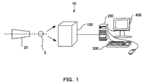
- FIG. 1 is a schematic illustration showing a configuration example of an X-ray measurement system 10.
- the X-ray measurement system 10 is configured with an X-ray source 20, a sample S, an X-ray detector 100, and an X-ray data processing apparatus 200.
- the X-ray source 20 generates an X-ray by causing an electron flux radiated from a filament as a cathode, for example, to collide with a rotor target as an anti-cathode.
- the X-ray radiated from the X-ray source 20 is a so-called point-focused X-ray beam having a circular or rectangular dot-like cross-sectional shape.
- the X-ray source 20 into an X-ray source having multi wavelengths by providing a plurality of kinds of metals having atomic numbers different from each other (e.g., Mo and Cu) on the outer peripheral surface of the rotor target.
- metals having atomic numbers different from each other (e.g., Mo and Cu)
- an X-ray is radiated including the CuK ⁇ -ray (wavelength: 1.542 ⁇ ) of a characteristic ray
- MoK ⁇ -ray wavelength: 0.711 A
- the Cuk ⁇ -ray and the MoK ⁇ -ray which are characteristic X-rays of target materials different from each other are mixed in the X-ray emitted from the rotor target.
- the sample S is supported by a sample support device.
- the sample support device is determined depending on the characteristics of the sample S and the kind of measurement.
- the X-ray detector 100 detects a diffraction X-ray diffracted by the sample S and a fluorescent X-ray.
- the X-ray data processing apparatus 200 processes measured X-ray data of the diffraction X-ray and the fluorescent X-ray and displays the measurement result.
- the X-ray detector 100 and the X-ray data processing apparatus 200 will be described below in detail.
- FIG. 2 is a block diagram mainly showing configurations of the X-ray detector 100 and the X-ray data processing apparatus 200.
- the X-ray detector 100 includes a plurality of pixels 110 for X-ray reception (detection parts) and is a two-dimensional semiconductor detector, for example.
- the plurality of pixels 110 is arrayed two-dimensionally and arranged regularly.
- the detector is not limited to the two-dimensional semiconductor detector and may be a one-dimensional semiconductor detector.
- a sorting circuit 120 is connected to each of the plurality of pixels 110, and further a counter unit 130 is connected to each of the sorting circuits 120.
- a counter read-out circuit 150 is connected to each of the counter units 130.
- the sorting circuit 120 sorts pulse signals from the pixel 110 for each X-ray wavelength and outputs the result.
- the counter unit 130 counts the number of signals sorted for each wavelength by the sorting unit 120.
- the counter unit 130 includes the same number of counter circuits as the number of sorts so as to cause the number of pulse signals sorted by the sorting circuit 120 to be counted for each of the sorts, for example.
- the output signal of the counter read-out circuit 150 is transmitted to the X-ray data processing apparatus 200 via a communication line as X-ray data separated by an energy threshold value.
- the X-ray data processing apparatus 200 is a personal computer, for example.
- the personal computer is configured with a CPU for operational control, a memory for data storage, system software stored in a predetermined region within the memory, application program software stored in another predetermined region within the memory, and the like, for example.
- the X-ray data processing apparatus 200 is connected with a keyboard or the like as an input unit 300 to receive a user input. A user can perform the display of the measurement result, the instruction of the correction, and the like via the input unit 300. Further, the input unit 300 receives the input of data regarding the X-ray source and the detection energy threshold value.
- the X-ray source includes not only the X-ray source for sample irradiation but also a fluorescent X-ray source.
- the X-ray data processing apparatus 200 is connected with an output unit 400 such as a display or a printer. The output unit 400 outputs the measurement result in response to an instruction from the X-ray data processing apparatus 200.
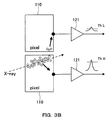
- FIG. 3A and FIG. 3B are schematic illustrations showing X-ray detection in a case where the charge share is caused and a case where the charge share is not caused, respectively.
- FIG. 3A when the X-ray enters only a single pixel 110, the charge share is not caused and accurate measurement is possible.
- FIG. 3B a charge cloud generated near the surface of the X-ray detector 100 spreads until reaching an electrode to cause the charge share. Due to the charge share caused across the two pixels 110, the peak detected in one pixel 110 becomes low and a low peak is also detected in the other pixel 110.
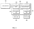
- FIG. 4 is a block diagram mainly showing a configuration of the X-ray data processing apparatus 200.
- the X-ray data processing apparatus 200 includes a management unit 210, a data storage unit 220, an effective area ratio calculation unit 230 and a correction unit 250, and estimates a true value from the X-ray count value.
- the X-ray data processing apparatus 200 may be used for separating diffraction X-ray data sets of a plurality of kinds of radiation sources, and may be used for separating the fluorescent X-ray from the diffraction X-ray data.
- the management unit 210 receives and manages the count value detected by the X-ray detector 100 for each pixel. For example, the management unit 210 determines the diffraction X-ray intensity for each wavelength and stores the resultant data in association with the address (i, j) of the pixel 110.
- the management unit 210 can display both diffraction image data sets of a stored diffraction X-ray image of the Cu X-ray source and a stored diffraction X-ray image of the Mo X-ray source, for example, on the output unit 400 in response to a user instruction. It is possible to display either one of the diffraction images, and also it is possible to display both of the images at the same time.
- the data storage unit 220 stores the data regarding the sensor material, structure, and pixel of the X-ray detector 100, and the data regarding the X-ray source 20 and the detection energy threshold value.
- the data regarding the pixel is data to express the pixel size and shape and the distribution of the charge spread within the sensor which are preliminarily stored in accordance with the pixel.
- the data regarding the X-ray source 20 and the detection energy threshold value is data to express a condition when the X-ray measurement system 10 is used and input by the user. Thereby, it is possible to estimate the influence of the charge share and calculate the effective area ratio depending on the pixel characteristics and shape.
- the effective area ratio calculation unit 230 calculates a ratio of a detection ability under the influence of the charge share to an original detection ability in a pixel as an effective area ratio of the pixel using the data regarding the pixel and the input data. In particular, for a plurality of X-ray sources and a plurality of threshold values, the effective area ratio calculation unit 230 calculates an effective area ratio for each of the X-ray sources and each of the detection energy threshold values.
- the correction unit 250 corrects the managed count value using the calculated effective area ratio to estimate a true value. In this manner, it is possible to correct the X-ray count value which is detected by the pixel array X-ray detector of the photon counting system under the influence of the charge share. Specifically, for the plurality of X-ray sources and the plurality of threshold values, the correction unit 250 expresses the calculated effective area ratio as a coefficient of simultaneous equations and, using the simultaneous equations, performs linear transformation of the count value for each of the detection energy threshold values to a correction value for each of the X-ray sources. Thereby, it is possible to reduce the influence of the charge share having a wavelength dependence even when a multi-wavelength X-ray enters the pixel.
- the effective area ratio of the charge share has a dependence on a threshold wavelength and the wavelength of an incident X-ray.
- the count value of the X-ray having reached the pixel is estimated for each wavelength by the use of this wavelength dependence and a count value measured by the plurality of threshold values.
- ⁇ is the wavelength of a target X-ray
- ⁇ TH is a threshold wavelength of the detection circuit.
- the above X-ray measurement system 10 can be used for separating a polychromatic radiation source.
- diffraction X-ray intensities of the Cu radiation source and the Mo radiation source I Cu and I Mo can be obtained by the following formula (4) by the use of the X-ray count values I H and I L which are separated by a high energy side threshold value and a low energy side threshold value, respectively.
- the above X-ray measurement system 10 can be applied to the regeneration of a uniformity correction table after temperature correction without hypothetical uniform irradiation.
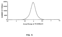
- FIG. 5 is a graph showing the gain variation of the ROIC.
- the influence of the charge share is different in magnitude depending on the size of a pixel, and the effective area ratio is also different.
- FIG. 6 is a table showing the influence of the charge share depending on the pixel size and the threshold value. When a variation of approximately 1 keV is caused with respect to a set value because of the variation in the performance of the ROIC, the count value of the X-ray varies in approximately 8%.
- FIG. 7 is a graph showing an actually measured X-ray profile and an effective area ratio curve for each of the X-ray sources. In the calculation, the effective area ratio curve was assumed to have the center of a noise peak at 0 keV and the threshold value was calculated.
- FIG. 8A is an illustration showing an image in a case without the correction
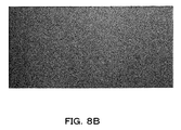
- FIG. 8B is an illustration showing an image with the correction using the effective area ratio. In the case without the correction, the overall count value is small, and, on the other side, in the case with the correction, the overall count value becomes large.
- FIG. 9 is a graph showing intensity distributions in cases with and without the correction using the effective area ratio.
- the overall count value is small, and the count value variation among the pixels becomes large.
- the overall count value is large and the count value variation among the pixels becomes small.
- a diffraction pattern was photographed when a powder sample made of iron was irradiated with an X-ray by the use of the Cu radiation source under the same condition as in above Examples.
- the photographing was performed with a threshold value set to 7 keV for reducing the fluorescent X-ray of Fe (fluorescent reduction mode).
- X-ray images were photographed at threshold values of 5 keV and 7 keV, respectively.
- FIG. 10 is a graph showing an X-ray intensity measured in the fluorescent X-ray reduction mode and an X-ray intensity in which the fluorescent X-ray is separated by the correction using the effective area ratio.
- the separated image formed by the Cu radiation source (8.04 keV) was obtained as an image corresponding to an image formed by a Cu radiation source and obtained when photographed at a threshold value of 4.1 keV.
- the image formed by Fe radiation source (6.4 keV) was obtained as an image corresponding to an image formed by the Fe radiation source when photographed at a threshold value of 3.3 keV.
- FIG. 11 is an illustration showing images measured at threshold values of 5 keV and 7 keV, respectively, (upper part) and a Cu radiation source image and an Fe radiation source image corrected by the use of the effective area ratio (lower part).
- the diffraction line becomes clear and it is found that the fluorescent X-ray can be separated and removed as a background.
Landscapes
- Physics & Mathematics (AREA)
- Health & Medical Sciences (AREA)
- Life Sciences & Earth Sciences (AREA)
- General Physics & Mathematics (AREA)
- High Energy & Nuclear Physics (AREA)
- Molecular Biology (AREA)
- Spectroscopy & Molecular Physics (AREA)
- Analytical Chemistry (AREA)
- Chemical & Material Sciences (AREA)
- Biochemistry (AREA)
- General Health & Medical Sciences (AREA)
- Immunology (AREA)
- Pathology (AREA)
- Measurement Of Radiation (AREA)
- Analysing Materials By The Use Of Radiation (AREA)
- Apparatus For Radiation Diagnosis (AREA)
Abstract
Description
- The present invention relates to an X-ray data processing apparatus for estimating a true value from a counted value for X-ray intensity of a specific X-ray source and to a method and program for the same.
- In a pixel array detector of a photon counting system, typically a monolithic sensor is used and therefore a definite boundary does not exist between pixels within the sensor. Typically only a read-out pad portion is formed in a pixel shape on the side connected to a read-out chip (refer to Patent Literature 1).
- Therefore, when a carrier diffuses in a boundary part of neighboring pixels, there occurs a phenomenon called charge share in which a charge corresponding to one photon is shared between the pixels. Because of this charge share, even if the intensity of an incident X-ray is constant, there exists a case where the count becomes larger than an original count or a case where the count becomes smaller than the original count, depending on a threshold value set for each of the pixels.
- While, conventionally, measurement has been performed neglecting the influence of the charge share, or the measurement has been performed minimizing the influence by setting an appropriate value to the threshold value, such a method cannot remove the effect of the charge share. On the other side, there has been performed a study of mounting a circuit for cancelling the influence itself of the charge share between pixels in the read-out chip (refer to Non-patent Literature 1).
-
- Patent Literature 1:
Japanese Patent Laid-Open Publication No. 2012-242111 - Patent Literature 2:
Japanese Patent Laid-Open Publication No. 2014-159973 - Non-patent Literature 1: H.E. Nilsson, B. Norlin, Frojdh, L. Tlustos, "Charge sharing suppression using pixel-to-pixel communication in photon counting X-ray imaging systems", Nuclear Instruments & Methods in Physics Research, Available online 6 February, A576, 2007, 243-247
- However, the method of mounting the circuit for cancelling the influence of the charge share needs to compare signal wave heights between the pixels. Therefore, the mounting of the comparator occupies a considerable area and variation is caused in a threshold value for comparison between the comparators. Further, when the pixel size is small, it is difficult to handle the charge share across a plurality of pixels.
- The present invention has been achieved in view of such a situation, and aims to provide an X-ray data processing apparatus capable of correcting an X-ray count value which is detected by a pixel array X-ray detector of a photon counting system under the influence of the charge share, without using a comparator or the like.
- (1) For achieving the above purpose, an X-ray data processing apparatus of the present invention is an X-ray data processing apparatus that estimates a true value from an X-ray count value detected by a pixel array X-ray detector of a photon counting system, the apparatus including: a management unit to receive and manage a count value for each detection part; an effective area ratio calculation unit to calculate a ratio of a detection ability under influence of charge share to an original detection ability in the detection part as an effective area ratio of the detection part using data regarding the detection part and data regarding an X-ray source and a detection energy threshold value; and a correction unit to correct the managed count value using the calculated effective area ratio to estimate a true value. Thereby, it is possible to correct the X-ray count value which is detected by the pixel array X-ray detector of the photon counting system under the influence of the charge share without using a comparator or the like.
- (2) Further, in the X-ray data processing apparatus of the present invention, the effective area ratio calculation unit calculates the effective area ratio for each X-ray source and each detection energy threshold value, and the correction unit expresses the calculated effective area ratio as a coefficient of simultaneous equations and performs linear transformation of a count value for each detection energy threshold value to a correction value for each X-ray source using the simultaneous equations. Thereby, it is possible to reduce the influence of the charge share having a wavelength dependence even when a multi-wavelength X-ray enters the detection part.
- (3) Further, in the X-ray data processing apparatus of the present invention, the data regarding the detection part is data which is preliminarily stored in accordance with the detection part and expresses a size of the detection part and a distribution of charge spread within the detection part. Thereby, it is possible to estimate the influence of the charge share and calculate the effective area ratio depending on the characteristics and the shape of the detection part.
- (4) Further, a method of the present invention is a method of X-ray data processing for estimating a true value from an X-ray count value detected by a pixel array X-ray detector of a photon counting system, the method comprising the steps of: receiving and managing a count value for each detection part; calculating a ratio of a detection ability under influence of charge share to an original detection ability in the detection part as an effective area ratio of the detection part using data regarding the detection part and data regarding an X-ray source and a detection energy threshold value; and correcting the managed count value using the calculated effective area ratio to estimate a true value. Thereby, it is possible to correct the influence of the charge share.
- (5) Further, a program of the present invention is a program of X-ray data processing for estimating a true value from an X-ray count value detected by a pixel array X-ray detector of a photon counting system, the program causing a computer to execute a series of processing comprising the processes of: receiving and managing a count value for each detection part; calculating a ratio of a detection ability under influence of charge share to an original detection ability in the detection part as an effective area ratio of the detection part using data regarding the detection part and data regarding an X-ray source and a detection energy threshold value; and correcting the managed count value using the calculated effective area ratio to estimate a true value. Thereby, it is possible to correct the influence of the charge share.
- According to the present invention, it is possible to correct the X-ray count value which is detected by the pixel array X-ray detector of the photon counting system under the influence of the charge share, without using a comparator or the like.
-
-
FIG. 1 is a schematic illustration showing a configuration of an X-ray diffraction system of the present invention. -
FIG. 2 is a block diagram mainly showing configurations of an X-ray detector and an X-ray data processing apparatus. -
FIG. 3A andFIG. 3B are schematic illustrations showing X-ray detection in a case where the charge share is not caused and a case where the charge share is caused, respectively. -
FIG. 4 is a block diagram mainly showing a configuration of the X-ray data processing apparatus. -
FIG. 5 is a graph showing gain variation of an ROIC. -
FIG. 6 is a table showing an influence of the charge share in accordance with a pixel size and a threshold value. -
FIG. 7 is a graph showing an actually measured X-ray profile and an effective area ratio curve for each X-ray source. -
FIG. 8A andFIG. 8B are illustrations showing respective images in a case without correction and in a case with correction using an effective area ratio. -
FIG. 9 is a graph showing intensity distributions in cases with and without correction using an effective area ratio. -
FIG. 10 is a graph showing an X-ray intensity measured in the fluorescent X-ray reduction mode and an X-ray intensity in which the fluorescent X-ray is removed by the correction using the effective area ratio. -
FIG. 11 is an illustration showing an image measured at each of threshold values of 5 keV and 7 keV (upper part), and a Cu radiation source image and an Fe radiation source image corrected by the use of effective area ratios (lower part). - Next, embodiments of the present invention will be explained with reference to the drawings. For easy understanding of the explanation, the same reference number is attached to the same constituent in each of the drawings and duplicated explanation will be omitted.
-
FIG. 1 is a schematic illustration showing a configuration example of anX-ray measurement system 10. As shown inFIG. 1 , theX-ray measurement system 10 is configured with anX-ray source 20, a sample S, anX-ray detector 100, and an X-raydata processing apparatus 200. - The
X-ray source 20 generates an X-ray by causing an electron flux radiated from a filament as a cathode, for example, to collide with a rotor target as an anti-cathode. The X-ray radiated from theX-ray source 20 is a so-called point-focused X-ray beam having a circular or rectangular dot-like cross-sectional shape. - It is possible to convert the
X-ray source 20 into an X-ray source having multi wavelengths by providing a plurality of kinds of metals having atomic numbers different from each other (e.g., Mo and Cu) on the outer peripheral surface of the rotor target. When an electron collides with the Cu target, an X-ray is radiated including the CuKα-ray (wavelength: 1.542 Å) of a characteristic ray, and, when an electron collides with the Mo target, an X-ray is radiated including the MoKα-ray (wavelength: 0.711 A) of a characteristic ray. The Cukα-ray and the MoKα-ray which are characteristic X-rays of target materials different from each other are mixed in the X-ray emitted from the rotor target. - The sample S is supported by a sample support device. The sample support device is determined depending on the characteristics of the sample S and the kind of measurement. The
X-ray detector 100 detects a diffraction X-ray diffracted by the sample S and a fluorescent X-ray. The X-raydata processing apparatus 200 processes measured X-ray data of the diffraction X-ray and the fluorescent X-ray and displays the measurement result. TheX-ray detector 100 and the X-raydata processing apparatus 200 will be described below in detail. -
FIG. 2 is a block diagram mainly showing configurations of theX-ray detector 100 and the X-raydata processing apparatus 200. TheX-ray detector 100 includes a plurality ofpixels 110 for X-ray reception (detection parts) and is a two-dimensional semiconductor detector, for example. The plurality ofpixels 110 is arrayed two-dimensionally and arranged regularly. Here, the detector is not limited to the two-dimensional semiconductor detector and may be a one-dimensional semiconductor detector. - A sorting
circuit 120 is connected to each of the plurality ofpixels 110, and further acounter unit 130 is connected to each of the sortingcircuits 120. A counter read-out circuit 150 is connected to each of thecounter units 130. - The
sorting circuit 120 sorts pulse signals from thepixel 110 for each X-ray wavelength and outputs the result. Thecounter unit 130 counts the number of signals sorted for each wavelength by thesorting unit 120. Thecounter unit 130 includes the same number of counter circuits as the number of sorts so as to cause the number of pulse signals sorted by the sortingcircuit 120 to be counted for each of the sorts, for example. The output signal of the counter read-out circuit 150 is transmitted to the X-raydata processing apparatus 200 via a communication line as X-ray data separated by an energy threshold value. - The X-ray
data processing apparatus 200 is a personal computer, for example. The personal computer is configured with a CPU for operational control, a memory for data storage, system software stored in a predetermined region within the memory, application program software stored in another predetermined region within the memory, and the like, for example. - The X-ray
data processing apparatus 200 is connected with a keyboard or the like as aninput unit 300 to receive a user input. A user can perform the display of the measurement result, the instruction of the correction, and the like via theinput unit 300. Further, theinput unit 300 receives the input of data regarding the X-ray source and the detection energy threshold value. Here, the X-ray source includes not only the X-ray source for sample irradiation but also a fluorescent X-ray source. Further, the X-raydata processing apparatus 200 is connected with anoutput unit 400 such as a display or a printer. Theoutput unit 400 outputs the measurement result in response to an instruction from the X-raydata processing apparatus 200. -
FIG. 3A andFIG. 3B are schematic illustrations showing X-ray detection in a case where the charge share is caused and a case where the charge share is not caused, respectively. As shown inFIG. 3A , when the X-ray enters only asingle pixel 110, the charge share is not caused and accurate measurement is possible. However, as shown inFIG. 3B , a charge cloud generated near the surface of theX-ray detector 100 spreads until reaching an electrode to cause the charge share. Due to the charge share caused across the twopixels 110, the peak detected in onepixel 110 becomes low and a low peak is also detected in theother pixel 110. -
FIG. 4 is a block diagram mainly showing a configuration of the X-raydata processing apparatus 200. The X-raydata processing apparatus 200 includes amanagement unit 210, adata storage unit 220, an effective arearatio calculation unit 230 and acorrection unit 250, and estimates a true value from the X-ray count value. Here, the X-raydata processing apparatus 200 may be used for separating diffraction X-ray data sets of a plurality of kinds of radiation sources, and may be used for separating the fluorescent X-ray from the diffraction X-ray data. - The
management unit 210 receives and manages the count value detected by theX-ray detector 100 for each pixel. For example, themanagement unit 210 determines the diffraction X-ray intensity for each wavelength and stores the resultant data in association with the address (i, j) of thepixel 110. Themanagement unit 210 can display both diffraction image data sets of a stored diffraction X-ray image of the Cu X-ray source and a stored diffraction X-ray image of the Mo X-ray source, for example, on theoutput unit 400 in response to a user instruction. It is possible to display either one of the diffraction images, and also it is possible to display both of the images at the same time. - The
data storage unit 220 stores the data regarding the sensor material, structure, and pixel of theX-ray detector 100, and the data regarding theX-ray source 20 and the detection energy threshold value. The data regarding the pixel is data to express the pixel size and shape and the distribution of the charge spread within the sensor which are preliminarily stored in accordance with the pixel. Further, the data regarding theX-ray source 20 and the detection energy threshold value is data to express a condition when theX-ray measurement system 10 is used and input by the user. Thereby, it is possible to estimate the influence of the charge share and calculate the effective area ratio depending on the pixel characteristics and shape. - The effective area
ratio calculation unit 230 calculates a ratio of a detection ability under the influence of the charge share to an original detection ability in a pixel as an effective area ratio of the pixel using the data regarding the pixel and the input data. In particular, for a plurality of X-ray sources and a plurality of threshold values, the effective arearatio calculation unit 230 calculates an effective area ratio for each of the X-ray sources and each of the detection energy threshold values. - The
correction unit 250 corrects the managed count value using the calculated effective area ratio to estimate a true value. In this manner, it is possible to correct the X-ray count value which is detected by the pixel array X-ray detector of the photon counting system under the influence of the charge share. Specifically, for the plurality of X-ray sources and the plurality of threshold values, thecorrection unit 250 expresses the calculated effective area ratio as a coefficient of simultaneous equations and, using the simultaneous equations, performs linear transformation of the count value for each of the detection energy threshold values to a correction value for each of the X-ray sources. Thereby, it is possible to reduce the influence of the charge share having a wavelength dependence even when a multi-wavelength X-ray enters the pixel. - The effective area ratio of the charge share has a dependence on a threshold wavelength and the wavelength of an incident X-ray. The count value of the X-ray having reached the pixel is estimated for each wavelength by the use of this wavelength dependence and a count value measured by the plurality of threshold values.
- Different two wavelengths are denoted by A and B, and different two appropriate threshold values are denoted by L and H. Further, the true numbers of photons in the X-rays which reach each pixel from radiation sources having the wavelengths A and B are denoted by IA and IB, respectively, and count values observed by the threshold values L and H are denoted by IL and IH, respectively. When the pixel effective area ratio is expressed as pLA for the case determined by the threshold value L and the wavelength A, the relationship between the observed count value and the true number of photons is obtained as in the following formula (1).

- When a matrix formed by the effective area ratios is denoted by P, the inverse matrix is obtained as in the following formula (2), and thereby it becomes possible to obtain the count values by the X-ray sources A and B independently from the count values observed without discriminating signals of the wavelengths A and B.

- When charge spread within the semiconductor sensor is assumed to follow a normal distribution and the standard deviation thereof is assumed to be σ, and one-side length of the pixel is denoted by d, the effective area ratio p can be approximated as in the following formula (3) (if d » σ).

- Here, λ is the wavelength of a target X-ray, and λTH is a threshold wavelength of the detection circuit. When d » σ does not hold, it is necessary to consider the effect of the four corners of the pixel.
- The above
X-ray measurement system 10 can be used for separating a polychromatic radiation source. For example, diffraction X-ray intensities of the Cu radiation source and the Mo radiation source ICu and IMo can be obtained by the following formula (4) by the use of the X-ray count values IH and IL which are separated by a high energy side threshold value and a low energy side threshold value, respectively.
- Further, the above
X-ray measurement system 10 can be applied to the regeneration of a uniformity correction table after temperature correction without hypothetical uniform irradiation. - Measurement was performed using the above
X-ray measurement system 10. A standard read-out integrated circuit (ROIC) used in theX-ray detector 100 has a gain variation. For example, even when the threshold value is set to 6 keV, the actually detected energy is varied for each pixel.FIG. 5 is a graph showing the gain variation of the ROIC. In the example shown inFIG. 5 , the gain has a distribution of an average value µ = 6.0 keV and a standard deviation σ = 0.2 keV. - The detection of an X-ray was performed using an X-ray detector including, on the surface, a rectangular pixel having a one-side length of 100 µm, a sensor thickness of 320 µm, and a carrier spread of a Gaussian distribution o = 5.0 µm. The influence of the charge share is different in magnitude depending on the size of a pixel, and the effective area ratio is also different.
FIG. 6 is a table showing the influence of the charge share depending on the pixel size and the threshold value. When a variation of approximately 1 keV is caused with respect to a set value because of the variation in the performance of the ROIC, the count value of the X-ray varies in approximately 8%. - The X-ray intensity of the CuK ray was measured with respect to a threshold value by the use of an X-ray detector as above, and also the effective area ratio of the X-ray detection was calculated with respect to the threshold value for each of Mo, Cu, Fe, and Cr radiation sources.
FIG. 7 is a graph showing an actually measured X-ray profile and an effective area ratio curve for each of the X-ray sources. In the calculation, the effective area ratio curve was assumed to have the center of a noise peak at 0 keV and the threshold value was calculated. Further, a Gaussian distribution of FWHM 24% (e.g., σ = 830 eV at 8.04 keV) was convoluted to an effective area-threshold value curve which was calculated for a monochromatic X-ray of 8.04 keV. As a result, the actually measured profile of CuK X-ray and the effective area ratio curve in the X-ray detection of the Cu radiation source coincided with each other approximately. - There will be explained an example of correcting the experimental data obtained by the use of the above X-ray measurement system, using the effective area ratio. An experimental result as in the following formula (5) is assumed to have been obtained by the use of the Cu radiation source.

- When simple correction is performed for the experimental result like this using the effective area ratio, the X-ray count value is corrected as in the following formula (6).

- When the above experimental result is obtained by the X-ray irradiation of the Cu radiation source onto a sample made of iron, reflecting a reduction amount by the fluorescent X-ray, it is possible to calculate the X-ray intensity ICu formed by the Cu radiation source and the X-ray intensity IFe of the fluorescent X-ray as in the following formula (7).

- Further, when it is clear that the incident X-ray is monochrome, a background and an intensity at an effective area ratio of 100% are obtained.

- An actually detected X-ray intensity was corrected by the use of the effective area ratio in an X-ray measurement system provided with an X-ray detector including a rectangular pixel having a one-side length of 100 µm. The count value correction among the ROICs connected to the sensor in parallel was performed by employing a simply averaged value.
FIG. 8A is an illustration showing an image in a case without the correction andFIG. 8B is an illustration showing an image with the correction using the effective area ratio. In the case without the correction, the overall count value is small, and, on the other side, in the case with the correction, the overall count value becomes large. -
FIG. 9 is a graph showing intensity distributions in cases with and without the correction using the effective area ratio. For the curve in the case without the correction, the overall count value is small, and the count value variation among the pixels becomes large. On the other side, for the curve in the case with the correction, the overall count value is large and the count value variation among the pixels becomes small. - A diffraction pattern was photographed when a powder sample made of iron was irradiated with an X-ray by the use of the Cu radiation source under the same condition as in above Examples. In this case, first, the photographing was performed with a threshold value set to 7 keV for reducing the fluorescent X-ray of Fe (fluorescent reduction mode). Next, X-ray images were photographed at threshold values of 5 keV and 7 keV, respectively. Then, for the photographed image, the simultaneous equations were solved by the use of the respective threshold values and the effective area ratios determined for each of the Cu radiation-source (8.04 keV) and the Fe radiation-source (6.4 keV) as the coefficient, and thereby the image was corrected and separated into images formed by the respective radiation sources (fluorescent separation mode).
-
FIG. 10 is a graph showing an X-ray intensity measured in the fluorescent X-ray reduction mode and an X-ray intensity in which the fluorescent X-ray is separated by the correction using the effective area ratio.FIG. 10 shows a measured data image of the fluorescent reduction mode and a fluorescent removal image which are plotted as average count profiles in a range of x = 360 to 411. It was found that the graph of the fluorescent separation mode had an improvement of approximately three times in the SBR (Signal to Background Ratio) with respect to the graph of the fluorescent reduction mode. - In this manner, the separated image formed by the Cu radiation source (8.04 keV) was obtained as an image corresponding to an image formed by a Cu radiation source and obtained when photographed at a threshold value of 4.1 keV. Further, the image formed by Fe radiation source (6.4 keV) was obtained as an image corresponding to an image formed by the Fe radiation source when photographed at a threshold value of 3.3 keV.
-
FIG. 11 is an illustration showing images measured at threshold values of 5 keV and 7 keV, respectively, (upper part) and a Cu radiation source image and an Fe radiation source image corrected by the use of the effective area ratio (lower part). Compared with the image of the threshold value of 7 keV (upper left part), in the Cu radiation source image corrected by the use of the effective area ratio (lower left part), the diffraction line becomes clear and it is found that the fluorescent X-ray can be separated and removed as a background. - 10
- X-ray measurement system
- 20
- X-ray source
- 100
- X-ray detector
- 110
- pixel (detection part)
- 120
- sorting circuit
- 130
- counter unit
- 150
- counter read-out circuit
- 200
- X-ray data processing apparatus
- 210
- management unit
- 220
- data storage unit
- 230
- effective area ratio calculation unit
- 250
- correction unit
- 300
- input unit
- 400
- output unit
- S
- sample
Claims (5)
- An X-ray data processing apparatus that estimates a true value from an X-ray count value detected by a pixel array X-ray detector of a photon counting system, the apparatus comprising:a management unit to receive and manage a count value for each detection part;an effective area ratio calculation unit to calculate a ratio of a detection ability under influence of charge share to an original detection ability in the detection part as an effective area ratio of the detection part using data regarding the detection part and data regarding an X-ray source and a detection energy threshold value; anda correction unit to correct the managed count value using the calculated effective area ratio to estimate a true value.
- The X-ray data processing apparatus according to claim 1, wherein
the effective area ratio calculation unit calculates the effective area ratio for each X-ray source and each detection energy threshold value, and
the correction unit expresses the calculated effective area ratio as a coefficient of simultaneous equations and performs linear transformation of a count value for each detection energy threshold value to a correction value for each X-ray source using the simultaneous equations. - The X-ray data processing apparatus according to claim 1 or 2, wherein
the data regarding the detection part is data which is preliminarily stored in accordance with the detection part and expresses a size of the detection part and a distribution of charge spread within the detection part. - A method of X-ray data processing for estimating a true value from an X-ray count value detected by a pixel array X-ray detector of a photon counting system, the method comprising the steps of:receiving and managing a count value for each detection part;calculating a ratio of a detection ability under influence of charge share to an original detection ability in the detection part as an effective area ratio of the detection part using data regarding the detection part and data regarding an X-ray source and a detection energy threshold value; andcorrecting the managed count value using the calculated effective area ratio to estimate a true value.
- A program of X-ray data processing for estimating a true value from an X-ray count value detected by a pixel array X-ray detector of a photon counting system, the program causing a computer to execute a series of processing comprising the processes of:receiving and managing a count value for each detection part;calculating a ratio of a detection ability under influence of charge share to an original detection ability in the detection part as an effective area ratio of the detection part using data regarding the detection part and data regarding an X-ray source and a detection energy threshold value; andcorrecting the managed count value using the calculated effective area ratio to estimate a true value.
Applications Claiming Priority (1)
| Application Number | Priority Date | Filing Date | Title |
|---|---|---|---|
| JP2015127043A JP6355598B2 (en) | 2015-06-24 | 2015-06-24 | X-ray data processing apparatus, method and program thereof |
Publications (2)
| Publication Number | Publication Date |
|---|---|
| EP3109677A1 true EP3109677A1 (en) | 2016-12-28 |
| EP3109677B1 EP3109677B1 (en) | 2019-11-06 |
Family
ID=56194236
Family Applications (1)
| Application Number | Title | Priority Date | Filing Date |
|---|---|---|---|
| EP16172408.3A Active EP3109677B1 (en) | 2015-06-24 | 2016-06-01 | X-ray data processing apparatus and method and program for the same |
Country Status (4)
| Country | Link |
|---|---|
| US (1) | US10222491B2 (en) |
| EP (1) | EP3109677B1 (en) |
| JP (1) | JP6355598B2 (en) |
| CN (1) | CN106290433B (en) |
Families Citing this family (4)
| Publication number | Priority date | Publication date | Assignee | Title |
|---|---|---|---|---|
| EP3508887A1 (en) * | 2018-01-09 | 2019-07-10 | Koninklijke Philips N.V. | Charge sharing calibration method and system |
| CN115023629B (en) * | 2020-01-27 | 2025-11-18 | 株式会社理学 | Control devices, systems, methods, and non-transitory computer-readable recording media |
| EP4425219A4 (en) * | 2021-10-27 | 2025-11-05 | Riken | RADIATION IMAGE SIGNAL PROCESSING METHOD, RADIATION IMAGE SIGNAL PROCESSING DEVICE, RADIATION IMAGE SYSTEM AND PROGRAM |
| US12358735B2 (en) * | 2022-01-31 | 2025-07-15 | Redlen Technologies, Inc. | Radiation detector unit with three-side buttable read-out integrated circuit and method of making thereof |
Citations (2)
| Publication number | Priority date | Publication date | Assignee | Title |
|---|---|---|---|---|
| JP2012242111A (en) | 2011-05-16 | 2012-12-10 | Nagoya Institute Of Technology | Method for manufacturing radiation detector |
| JP2014159973A (en) | 2013-02-19 | 2014-09-04 | Rigaku Corp | X-ray data processing device, x-ray data processing method and x-ray data processing program |
Family Cites Families (4)
| Publication number | Priority date | Publication date | Assignee | Title |
|---|---|---|---|---|
| US7667205B2 (en) * | 2005-10-05 | 2010-02-23 | Organisation Europeenne Pour La Recherche Nucleaire | Method for determining a particle and sensor device therefor |
| US8378310B2 (en) * | 2009-02-11 | 2013-02-19 | Prismatic Sensors Ab | Image quality in photon counting-mode detector systems |
| ITPI20120060A1 (en) * | 2012-05-15 | 2013-11-16 | Ronaldo Bellazzini | DIGITAL RADIOLOGICAL SENSOR |
| ES2696748T3 (en) * | 2013-12-09 | 2019-01-17 | Hamamatsu Photonics Kk | Two-dimensional photon counting element |
-
2015
- 2015-06-24 JP JP2015127043A patent/JP6355598B2/en active Active
-
2016
- 2016-06-01 EP EP16172408.3A patent/EP3109677B1/en active Active
- 2016-06-09 US US15/177,611 patent/US10222491B2/en active Active
- 2016-06-22 CN CN201610459652.0A patent/CN106290433B/en active Active
Patent Citations (2)
| Publication number | Priority date | Publication date | Assignee | Title |
|---|---|---|---|---|
| JP2012242111A (en) | 2011-05-16 | 2012-12-10 | Nagoya Institute Of Technology | Method for manufacturing radiation detector |
| JP2014159973A (en) | 2013-02-19 | 2014-09-04 | Rigaku Corp | X-ray data processing device, x-ray data processing method and x-ray data processing program |
Non-Patent Citations (2)
| Title |
|---|
| H.E. NILSSON; B. NORLIN; FROJDH, L. TLUSTOS: "Charge sharing suppression using pixel-to-pixel communication in photon counting X-ray imaging systems", NUCLEAR INSTRUMENTS & METHODS IN PHYSICS RESEARCH, vol. A576, 2007, pages 243 - 247, XP022072119, DOI: doi:10.1016/j.nima.2007.01.160 |
| KRAFT P ET AL: "Performance of single-photon-counting PILATUS detector modules", JOURNAL OF SYNCHROTRON RADIATION, WILEY-BLACKWELL MUNKSGAARD, DK, vol. 16, no. 3, 1 May 2009 (2009-05-01), pages 368 - 375, XP002632471, ISSN: 0909-0495, DOI: 10.1107/S0909049509009911 * |
Also Published As
| Publication number | Publication date |
|---|---|
| US20160377749A1 (en) | 2016-12-29 |
| EP3109677B1 (en) | 2019-11-06 |
| US10222491B2 (en) | 2019-03-05 |
| JP2017009504A (en) | 2017-01-12 |
| CN106290433A (en) | 2017-01-04 |
| CN106290433B (en) | 2020-03-27 |
| JP6355598B2 (en) | 2018-07-11 |
Similar Documents
| Publication | Publication Date | Title |
|---|---|---|
| US10209375B2 (en) | X-ray data processing apparatus, X-ray data processing method, and X-ray data processing program | |
| US10197684B2 (en) | Radiation imaging apparatus, control method thereof, and non-transitory computer-readable storage medium | |
| EP3342342B1 (en) | Radiation image processing method and radiographic system | |
| US10222491B2 (en) | X-ray data processing apparatus and method and program for the same | |
| Ramilli et al. | Measurements with MÖNCH, a 25 μm pixel pitch hybrid pixel detector | |
| US11249035B2 (en) | Two-step material decomposition calibration method for a full size photon counting computed tomography system | |
| Becker et al. | Characterization of CdTe sensors with Schottky contacts coupled to charge-integrating pixel array detectors for X-ray science | |
| Holden et al. | A color x-ray camera for 2–6 keV using a mass produced back illuminated complementary metal oxide semiconductor sensor | |
| Blaj et al. | X-ray imaging with ePix100a: a high-speed, high-resolution, low-noise camera | |
| US10641909B2 (en) | Method for processing a pulse generated by a detector of ionizing radiation | |
| US10101476B2 (en) | X-ray data processing apparatus and method and program therefor | |
| Dawiec et al. | Real-time control of the beam attenuation with XPAD hybrid pixel detector | |
| JP2011089901A (en) | Detection result correction method, radiation detection device and program using the same, and recording medium for recording the program | |
| VanMeter et al. | Pixel-to-pixel variation on a calibrated PILATUS3-based multi-energy soft x-ray detector | |
| Aamir et al. | Pixel sensitivity variations in a CdTe-Medipix2 detector using poly-energetic x-rays | |
| JP5796556B2 (en) | X-ray fluorescence analyzer | |
| Arora et al. | Dispersion-less spectrograph for absolute measurement of multi keV X-ray flux from high intensity laser produced plasmas | |
| JP2017164374A (en) | Radiation detecting device and radiation inspecting apparatus | |
| Ghani et al. | Image quality assessment of a photon counting detector in X-ray projection imaging | |
| GB2548352A (en) | Detector | |
| Sakai et al. | Conceptual design of Thomson scattering system with high wavelength resolution in magnetically confined plasmas for electron phase-space measurements | |
| Marchal | Discriminator threshold dependence of the Noise Power Spectrum in single-X-ray-photon counting silicon strip detectors | |
| Fang et al. | New method for optimizing the detection of low-energy soft X-rays (200–300 eV) in a CMOS detector | |
| Christodoulou et al. | DQE analysis of CdTe and Si sensor Timepix3 detectors | |
| Strüder et al. | Spatial resolution smaller than the pixel size? Yes we can! |
Legal Events
| Date | Code | Title | Description |
|---|---|---|---|
| PUAI | Public reference made under article 153(3) epc to a published international application that has entered the european phase |
Free format text: ORIGINAL CODE: 0009012 |
|
| STAA | Information on the status of an ep patent application or granted ep patent |
Free format text: STATUS: THE APPLICATION HAS BEEN PUBLISHED |
|
| AK | Designated contracting states |
Kind code of ref document: A1 Designated state(s): AL AT BE BG CH CY CZ DE DK EE ES FI FR GB GR HR HU IE IS IT LI LT LU LV MC MK MT NL NO PL PT RO RS SE SI SK SM TR |
|
| AX | Request for extension of the european patent |
Extension state: BA ME |
|
| STAA | Information on the status of an ep patent application or granted ep patent |
Free format text: STATUS: REQUEST FOR EXAMINATION WAS MADE |
|
| 17P | Request for examination filed |
Effective date: 20170529 |
|
| RBV | Designated contracting states (corrected) |
Designated state(s): AL AT BE BG CH CY CZ DE DK EE ES FI FR GB GR HR HU IE IS IT LI LT LU LV MC MK MT NL NO PL PT RO RS SE SI SK SM TR |
|
| GRAJ | Information related to disapproval of communication of intention to grant by the applicant or resumption of examination proceedings by the epo deleted |
Free format text: ORIGINAL CODE: EPIDOSDIGR1 |
|
| STAA | Information on the status of an ep patent application or granted ep patent |
Free format text: STATUS: GRANT OF PATENT IS INTENDED |
|
| GRAP | Despatch of communication of intention to grant a patent |
Free format text: ORIGINAL CODE: EPIDOSNIGR1 |
|
| INTG | Intention to grant announced |
Effective date: 20190612 |
|
| RIN1 | Information on inventor provided before grant (corrected) |
Inventor name: SAKUMURA, TAKUTO Inventor name: MATSUSHITA, KAZUYUKI Inventor name: NAKAYE, YASUKAZU |
|
| GRAS | Grant fee paid |
Free format text: ORIGINAL CODE: EPIDOSNIGR3 |
|
| GRAA | (expected) grant |
Free format text: ORIGINAL CODE: 0009210 |
|
| STAA | Information on the status of an ep patent application or granted ep patent |
Free format text: STATUS: THE PATENT HAS BEEN GRANTED |
|
| AK | Designated contracting states |
Kind code of ref document: B1 Designated state(s): AL AT BE BG CH CY CZ DE DK EE ES FI FR GB GR HR HU IE IS IT LI LT LU LV MC MK MT NL NO PL PT RO RS SE SI SK SM TR |
|
| RAP1 | Party data changed (applicant data changed or rights of an application transferred) |
Owner name: RIGAKU CORPORATION |
|
| REG | Reference to a national code |
Ref country code: GB Ref legal event code: FG4D |
|
| REG | Reference to a national code |
Ref country code: CH Ref legal event code: EP Ref country code: AT Ref legal event code: REF Ref document number: 1199520 Country of ref document: AT Kind code of ref document: T Effective date: 20191115 |
|
| REG | Reference to a national code |
Ref country code: IE Ref legal event code: FG4D |
|
| REG | Reference to a national code |
Ref country code: DE Ref legal event code: R096 Ref document number: 602016023606 Country of ref document: DE |
|
| REG | Reference to a national code |
Ref country code: NL Ref legal event code: FP |
|
| REG | Reference to a national code |
Ref country code: CH Ref legal event code: NV Representative=s name: VALIPAT S.A. C/O BOVARD SA NEUCHATEL, CH |
|
| REG | Reference to a national code |
Ref country code: LT Ref legal event code: MG4D |
|
| PG25 | Lapsed in a contracting state [announced via postgrant information from national office to epo] |
Ref country code: PT Free format text: LAPSE BECAUSE OF FAILURE TO SUBMIT A TRANSLATION OF THE DESCRIPTION OR TO PAY THE FEE WITHIN THE PRESCRIBED TIME-LIMIT Effective date: 20200306 Ref country code: FI Free format text: LAPSE BECAUSE OF FAILURE TO SUBMIT A TRANSLATION OF THE DESCRIPTION OR TO PAY THE FEE WITHIN THE PRESCRIBED TIME-LIMIT Effective date: 20191106 Ref country code: LV Free format text: LAPSE BECAUSE OF FAILURE TO SUBMIT A TRANSLATION OF THE DESCRIPTION OR TO PAY THE FEE WITHIN THE PRESCRIBED TIME-LIMIT Effective date: 20191106 Ref country code: SE Free format text: LAPSE BECAUSE OF FAILURE TO SUBMIT A TRANSLATION OF THE DESCRIPTION OR TO PAY THE FEE WITHIN THE PRESCRIBED TIME-LIMIT Effective date: 20191106 Ref country code: BG Free format text: LAPSE BECAUSE OF FAILURE TO SUBMIT A TRANSLATION OF THE DESCRIPTION OR TO PAY THE FEE WITHIN THE PRESCRIBED TIME-LIMIT Effective date: 20200206 Ref country code: LT Free format text: LAPSE BECAUSE OF FAILURE TO SUBMIT A TRANSLATION OF THE DESCRIPTION OR TO PAY THE FEE WITHIN THE PRESCRIBED TIME-LIMIT Effective date: 20191106 Ref country code: PL Free format text: LAPSE BECAUSE OF FAILURE TO SUBMIT A TRANSLATION OF THE DESCRIPTION OR TO PAY THE FEE WITHIN THE PRESCRIBED TIME-LIMIT Effective date: 20191106 Ref country code: NO Free format text: LAPSE BECAUSE OF FAILURE TO SUBMIT A TRANSLATION OF THE DESCRIPTION OR TO PAY THE FEE WITHIN THE PRESCRIBED TIME-LIMIT Effective date: 20200206 Ref country code: GR Free format text: LAPSE BECAUSE OF FAILURE TO SUBMIT A TRANSLATION OF THE DESCRIPTION OR TO PAY THE FEE WITHIN THE PRESCRIBED TIME-LIMIT Effective date: 20200207 |
|
| PG25 | Lapsed in a contracting state [announced via postgrant information from national office to epo] |
Ref country code: HR Free format text: LAPSE BECAUSE OF FAILURE TO SUBMIT A TRANSLATION OF THE DESCRIPTION OR TO PAY THE FEE WITHIN THE PRESCRIBED TIME-LIMIT Effective date: 20191106 Ref country code: IS Free format text: LAPSE BECAUSE OF FAILURE TO SUBMIT A TRANSLATION OF THE DESCRIPTION OR TO PAY THE FEE WITHIN THE PRESCRIBED TIME-LIMIT Effective date: 20200306 Ref country code: RS Free format text: LAPSE BECAUSE OF FAILURE TO SUBMIT A TRANSLATION OF THE DESCRIPTION OR TO PAY THE FEE WITHIN THE PRESCRIBED TIME-LIMIT Effective date: 20191106 |
|
| PG25 | Lapsed in a contracting state [announced via postgrant information from national office to epo] |
Ref country code: AL Free format text: LAPSE BECAUSE OF FAILURE TO SUBMIT A TRANSLATION OF THE DESCRIPTION OR TO PAY THE FEE WITHIN THE PRESCRIBED TIME-LIMIT Effective date: 20191106 |
|
| PG25 | Lapsed in a contracting state [announced via postgrant information from national office to epo] |
Ref country code: EE Free format text: LAPSE BECAUSE OF FAILURE TO SUBMIT A TRANSLATION OF THE DESCRIPTION OR TO PAY THE FEE WITHIN THE PRESCRIBED TIME-LIMIT Effective date: 20191106 Ref country code: DK Free format text: LAPSE BECAUSE OF FAILURE TO SUBMIT A TRANSLATION OF THE DESCRIPTION OR TO PAY THE FEE WITHIN THE PRESCRIBED TIME-LIMIT Effective date: 20191106 Ref country code: RO Free format text: LAPSE BECAUSE OF FAILURE TO SUBMIT A TRANSLATION OF THE DESCRIPTION OR TO PAY THE FEE WITHIN THE PRESCRIBED TIME-LIMIT Effective date: 20191106 Ref country code: CZ Free format text: LAPSE BECAUSE OF FAILURE TO SUBMIT A TRANSLATION OF THE DESCRIPTION OR TO PAY THE FEE WITHIN THE PRESCRIBED TIME-LIMIT Effective date: 20191106 Ref country code: ES Free format text: LAPSE BECAUSE OF FAILURE TO SUBMIT A TRANSLATION OF THE DESCRIPTION OR TO PAY THE FEE WITHIN THE PRESCRIBED TIME-LIMIT Effective date: 20191106 |
|
| REG | Reference to a national code |
Ref country code: DE Ref legal event code: R097 Ref document number: 602016023606 Country of ref document: DE |
|
| REG | Reference to a national code |
Ref country code: AT Ref legal event code: MK05 Ref document number: 1199520 Country of ref document: AT Kind code of ref document: T Effective date: 20191106 |
|
| PG25 | Lapsed in a contracting state [announced via postgrant information from national office to epo] |
Ref country code: SM Free format text: LAPSE BECAUSE OF FAILURE TO SUBMIT A TRANSLATION OF THE DESCRIPTION OR TO PAY THE FEE WITHIN THE PRESCRIBED TIME-LIMIT Effective date: 20191106 Ref country code: SK Free format text: LAPSE BECAUSE OF FAILURE TO SUBMIT A TRANSLATION OF THE DESCRIPTION OR TO PAY THE FEE WITHIN THE PRESCRIBED TIME-LIMIT Effective date: 20191106 |
|
| PLBE | No opposition filed within time limit |
Free format text: ORIGINAL CODE: 0009261 |
|
| STAA | Information on the status of an ep patent application or granted ep patent |
Free format text: STATUS: NO OPPOSITION FILED WITHIN TIME LIMIT |
|
| 26N | No opposition filed |
Effective date: 20200807 |
|
| PG25 | Lapsed in a contracting state [announced via postgrant information from national office to epo] |
Ref country code: AT Free format text: LAPSE BECAUSE OF FAILURE TO SUBMIT A TRANSLATION OF THE DESCRIPTION OR TO PAY THE FEE WITHIN THE PRESCRIBED TIME-LIMIT Effective date: 20191106 Ref country code: SI Free format text: LAPSE BECAUSE OF FAILURE TO SUBMIT A TRANSLATION OF THE DESCRIPTION OR TO PAY THE FEE WITHIN THE PRESCRIBED TIME-LIMIT Effective date: 20191106 |
|
| PG25 | Lapsed in a contracting state [announced via postgrant information from national office to epo] |
Ref country code: IT Free format text: LAPSE BECAUSE OF FAILURE TO SUBMIT A TRANSLATION OF THE DESCRIPTION OR TO PAY THE FEE WITHIN THE PRESCRIBED TIME-LIMIT Effective date: 20191106 Ref country code: MC Free format text: LAPSE BECAUSE OF FAILURE TO SUBMIT A TRANSLATION OF THE DESCRIPTION OR TO PAY THE FEE WITHIN THE PRESCRIBED TIME-LIMIT Effective date: 20191106 |
|
| GBPC | Gb: european patent ceased through non-payment of renewal fee |
Effective date: 20200601 |
|
| PG25 | Lapsed in a contracting state [announced via postgrant information from national office to epo] |
Ref country code: LU Free format text: LAPSE BECAUSE OF NON-PAYMENT OF DUE FEES Effective date: 20200601 |
|
| REG | Reference to a national code |
Ref country code: BE Ref legal event code: MM Effective date: 20200630 |
|
| PG25 | Lapsed in a contracting state [announced via postgrant information from national office to epo] |
Ref country code: FR Free format text: LAPSE BECAUSE OF NON-PAYMENT OF DUE FEES Effective date: 20200630 Ref country code: IE Free format text: LAPSE BECAUSE OF NON-PAYMENT OF DUE FEES Effective date: 20200601 Ref country code: GB Free format text: LAPSE BECAUSE OF NON-PAYMENT OF DUE FEES Effective date: 20200601 |
|
| PG25 | Lapsed in a contracting state [announced via postgrant information from national office to epo] |
Ref country code: BE Free format text: LAPSE BECAUSE OF NON-PAYMENT OF DUE FEES Effective date: 20200630 |
|
| PG25 | Lapsed in a contracting state [announced via postgrant information from national office to epo] |
Ref country code: TR Free format text: LAPSE BECAUSE OF FAILURE TO SUBMIT A TRANSLATION OF THE DESCRIPTION OR TO PAY THE FEE WITHIN THE PRESCRIBED TIME-LIMIT Effective date: 20191106 Ref country code: MT Free format text: LAPSE BECAUSE OF FAILURE TO SUBMIT A TRANSLATION OF THE DESCRIPTION OR TO PAY THE FEE WITHIN THE PRESCRIBED TIME-LIMIT Effective date: 20191106 Ref country code: CY Free format text: LAPSE BECAUSE OF FAILURE TO SUBMIT A TRANSLATION OF THE DESCRIPTION OR TO PAY THE FEE WITHIN THE PRESCRIBED TIME-LIMIT Effective date: 20191106 |
|
| PG25 | Lapsed in a contracting state [announced via postgrant information from national office to epo] |
Ref country code: MK Free format text: LAPSE BECAUSE OF FAILURE TO SUBMIT A TRANSLATION OF THE DESCRIPTION OR TO PAY THE FEE WITHIN THE PRESCRIBED TIME-LIMIT Effective date: 20191106 |
|
| PGFP | Annual fee paid to national office [announced via postgrant information from national office to epo] |
Ref country code: DE Payment date: 20250618 Year of fee payment: 10 |
|
| PGFP | Annual fee paid to national office [announced via postgrant information from national office to epo] |
Ref country code: NL Payment date: 20250618 Year of fee payment: 10 |
|
| PGFP | Annual fee paid to national office [announced via postgrant information from national office to epo] |
Ref country code: CH Payment date: 20250701 Year of fee payment: 10 |