EP3109537A1 - Polymeric protective cover for electrical beams in a light device of a motor vehicle - Google Patents
Polymeric protective cover for electrical beams in a light device of a motor vehicle Download PDFInfo
- Publication number
- EP3109537A1 EP3109537A1 EP16174439.6A EP16174439A EP3109537A1 EP 3109537 A1 EP3109537 A1 EP 3109537A1 EP 16174439 A EP16174439 A EP 16174439A EP 3109537 A1 EP3109537 A1 EP 3109537A1
- Authority
- EP
- European Patent Office
- Prior art keywords
- light device
- protective envelope
- envelope
- electrical
- polymer
- Prior art date
- Legal status (The legal status is an assumption and is not a legal conclusion. Google has not performed a legal analysis and makes no representation as to the accuracy of the status listed.)
- Withdrawn
Links
Images


Classifications
-
- F—MECHANICAL ENGINEERING; LIGHTING; HEATING; WEAPONS; BLASTING
- F21—LIGHTING
- F21S—NON-PORTABLE LIGHTING DEVICES; SYSTEMS THEREOF; VEHICLE LIGHTING DEVICES SPECIALLY ADAPTED FOR VEHICLE EXTERIORS
- F21S45/00—Arrangements within vehicle lighting devices specially adapted for vehicle exteriors, for purposes other than emission or distribution of light
-
- B—PERFORMING OPERATIONS; TRANSPORTING
- B60—VEHICLES IN GENERAL
- B60Q—ARRANGEMENT OF SIGNALLING OR LIGHTING DEVICES, THE MOUNTING OR SUPPORTING THEREOF OR CIRCUITS THEREFOR, FOR VEHICLES IN GENERAL
- B60Q1/00—Arrangement of optical signalling or lighting devices, the mounting or supporting thereof or circuits therefor
- B60Q1/0088—Details of electrical connections
-
- F—MECHANICAL ENGINEERING; LIGHTING; HEATING; WEAPONS; BLASTING
- F21—LIGHTING
- F21S—NON-PORTABLE LIGHTING DEVICES; SYSTEMS THEREOF; VEHICLE LIGHTING DEVICES SPECIALLY ADAPTED FOR VEHICLE EXTERIORS
- F21S45/00—Arrangements within vehicle lighting devices specially adapted for vehicle exteriors, for purposes other than emission or distribution of light
- F21S45/10—Protection of lighting devices
-
- H—ELECTRICITY
- H01—ELECTRIC ELEMENTS
- H01B—CABLES; CONDUCTORS; INSULATORS; SELECTION OF MATERIALS FOR THEIR CONDUCTIVE, INSULATING OR DIELECTRIC PROPERTIES
- H01B7/00—Insulated conductors or cables characterised by their form
- H01B7/17—Protection against damage caused by external factors, e.g. sheaths or armouring
- H01B7/18—Protection against damage caused by wear, mechanical force or pressure; Sheaths; Armouring
- H01B7/1805—Protections not provided for in groups H01B7/182 - H01B7/26
-
- F—MECHANICAL ENGINEERING; LIGHTING; HEATING; WEAPONS; BLASTING
- F21—LIGHTING
- F21S—NON-PORTABLE LIGHTING DEVICES; SYSTEMS THEREOF; VEHICLE LIGHTING DEVICES SPECIALLY ADAPTED FOR VEHICLE EXTERIORS
- F21S45/00—Arrangements within vehicle lighting devices specially adapted for vehicle exteriors, for purposes other than emission or distribution of light
- F21S45/40—Cooling of lighting devices
- F21S45/47—Passive cooling, e.g. using fins, thermal conductive elements or openings
Definitions
- the present invention relates to a light device of a motor vehicle comprising at least one electrical cable surrounded at least in part by an electrically conductive protective envelope of polymeric material.
- EP-2 266 845 is known a means for partially mechanically protecting the electrical harnesses inside a housing for automotive projector. This means consists in inserting the electrical bundles inside a gutter made of a rigid plastic material.
- the electrical bundles as arranged in these gutters when subjected to an electrical supply, have the disadvantage of generating electromagnetic fields electromagnetically influencing the internal and / or external electronic elements of the projector and thus of impair the operation of the surrounding components inside the automotive headlight housing.
- the object of the present invention is to overcome the disadvantages of the techniques of the prior art by providing a vehicle light device automobile comprising at least one electrical cable, significantly limiting the electrical and / or electromagnetic disturbances induced by the electric cable when it is subjected to a power supply, while allowing positioning and easy connection of said electric cable within a housing for a light device, and in particular within a housing for a car projector.
- the present invention relates to a light device of a motor vehicle comprising at least one light module and at least one electric cable, characterized in that at least a longitudinal portion of said electric cable is surrounded at least partially or completely by at least one protective envelope, the protective envelope being an electrically conductive polymeric envelope.
- the electric cable (s), in particular of the electric harness type, protected (s) by the protective envelope can be easily handled and positioned in a housing for light device, and in particular in a housing for automotive projector.
- the protective envelope advantageously makes it possible to significantly limit, or even to avoid, the electromagnetic nuisances, such as in particular the electrical nuisances, between the electric cable (s) and their environment, and vice versa. .
- the term "electrical cable” means one or more elongated electrically conductive element (s) surrounded (s) by at least one electrically insulating layer, the electrically insulating layer being able to be in direct physical contact. with the elongated electrically conductive element (s).
- the electric cable conventionally comprises a longitudinal axis.
- the elongate electrically conductive element constituting the electrical cable of the invention is conventionally intended to distribute the electric current between different electrical devices, in particular to distribute the electric current to at least one motor vehicle light module. More particularly, the electrical cable of the invention is intended to be connected to, or connected to, at least one motor vehicle light module.
- the elongate electrically conductive element of the electrical cable may typically be a wire or a plurality of twisted or unreinforced wires, especially copper and / or aluminum (at the zero oxidation state), or one of their alloys.
- the elongated electrically conductive member of the electrical cable is made of copper (at the zero oxidation state).
- the electric cable may comprise one or more insulated electrical wires, surrounded or not by a protective sheath.
- the light device of a motor vehicle may comprise at least two electrical cables forming a set of electric cables, at least a longitudinal portion of said assembly being surrounded by said protective envelope.
- it may be at least two insulated electrical conductors, these two insulated conductors being surrounded by the protective envelope.
- the light device of a motor vehicle may comprise at least one bundle of electric cables (i.e. electric beam), at least one longitudinal portion of said bundle being surrounded by said protective envelope.
- electric cables i.e. electric beam
- the light device of a motor vehicle may comprise at least two bundles of electric cables forming a set of beams, at least a longitudinal portion of said set of bundles being surrounded by said protective envelope.
- the light device of a motor vehicle further comprises at least one electrical connector.
- Said electrical connector is in particular intended to connect the electrical cable to at least one light module.
- the bundle of electrical cables mentioned in the description may be more particularly a set of several electrical cables comprising one or more electrical connectors. More particularly, the bundle of electrical cables comprises several insulated electrical wires, which are preassembled, with one or more electrical connectors.
- the protective envelope is an envelope surrounding at least partially or completely at least a longitudinal portion of the electrical cable or cables.
- the protective envelope is a casing surrounding at least a portion, and preferably not in its entirety, at least a longitudinal portion of the electrical cable or cables.
- the protective envelope is a longitudinally open envelope on the portion of the electrical cable or cables to be protected. More particularly, the protective envelope has an open cross-sectional area. We can talk about an open protection envelope.
- the open protective envelope is intended to be associated with at least a portion of a light device housing, in order to form a closed assembly within which the electric cable or cables are positioned.
- the open protective envelope thus forms with the part of the housing with which it is associated, a protection element completely surrounding in its cross section at least a longitudinal portion of the electrical cable or cables.
- the open protective envelope may be fixed on the inner surface of the luminous device housing, by any holding means well known to those skilled in the art.
- the open protective envelope may be of the exoskeleton type.
- exoskeleton is understood to mean an external element (ie structurally independent) to the electrical cable (s) of the invention.
- the exoskeleton allows at least partly to support and mechanically protect said electric cable (s) of the invention.
- the exoskeleton may have a substantially constant thickness around the electrical cable or cables that it partially surrounds.
- the thickness of the exoskeleton is between 1 mm and 3.5 mm.
- the open protective envelope may further comprise at least a first opening for passing at least one electrical connector of the electrical cable.
- the open protective envelope may further comprise at least a second opening intended to allow the attachment of said envelope to the inner surface of a luminous device housing.
- the protective envelope is an envelope completely surrounding at least one longitudinal portion of the electrical cable or cables.
- the protective envelope is a longitudinally enclosed envelope on the portion of the electrical cable or cables to be protected. More particularly, the protective envelope has a closed surface in cross section. We can talk about a closed protective envelope.
- the closed protective envelope may be fixed on the inner surface of the luminous device housing, by any holding means well known to those skilled in the art, such as for example by screwing, gluing or riveting.
- the closed protective envelope may be of the cylindrical type, and may have a substantially constant thickness all around the electrical cable or cables.
- the thickness of the sheath is between 0.3 mm and 1.0 mm.
- the protective envelope can thus be of the protective sheath type.
- the protective envelope according to the invention is very different from the gutter of the prior art, the latter not completely surrounding the electric cables since the gutter is shaped "U" and is not a so-called closed surface.
- the protective envelope may comprise a protective envelope according to the first embodiment and a protective envelope according to the second embodiment.
- the protective envelope according to the invention in addition to playing a role of mechanical protection, advantageously makes it possible to form an electromagnetic shielding around the longitudinal zone of the electrical cable or cables that it partially or completely surrounds.
- This electromagnetic shield advantageously makes it possible for the components surrounding the electrical cable or cables to be protected from the electromagnetic fields that can be generated by the electric cable or cables when they are traversed by an electric current. It also allows, conversely, to the electrical cables protected by the protective envelope, to be preserved electromagnetic fields that can be generated by the electrical components and / or surrounding magnetic paths covered by electric currents.
- the portion of the electrical cable or cables covered by the protective envelope is preferably of sufficient length to make an electromagnetic barrier, especially an electrical barrier, between the electrical cable or cables and the components surrounding the electrical cable or cables. on the other hand, to avoid the harmful effects of electromagnetic fields.
- the dimensions, and in particular the length and thickness, of the protective envelope can also be adjusted to optimize the mechanical protection of the electrical cable or cables that surround it.
- the protective envelope of the invention extends longitudinally over the entire length of the electrical cable or cables to be protected.
- the protective envelope also allows to maintain together, and continuously on the area to be protected, several electrical cables. As a result, the manipulation and installation of the cable assembly surrounded by the protective envelope is greatly facilitated. In addition, the fixing of the electrical cable or cables surrounded by the protective envelope of the invention on the inner surface of a light device housing is optimized.
- the protective envelope is a so-called flexible envelope, as opposed to the gutter of the prior art which is rigid.
- the flexibility induced by the protective envelope advantageously facilitates its positioning inside a housing for light device.
- the protective envelope of the invention is more particularly an electrically conductive envelope of polymeric type.
- the expression "electrically conductive” or “electrically conductive” means an electrical conductivity of at least 1.10 -8 S / m (siemens per meter), preferably at least 1.10 -6 S / m. m, and preferably at least 1.10 -3 S / m, and preferably at most 1.10 3 S / m (at 25 ° C).
- the light device of the invention may comprise one or more protective envelope (s) according to the invention.
- the electrical conductivity of each envelope may be different.
- the electrical conductivity of the protective envelope according to the invention can easily be determined with the aid of an apparatus for measuring electrical conductivity, such as, for example, a device referenced AUTOSIGMA 3000, marketed by Sofranel.
- the protective envelope can be obtained from a polymer composition comprising at least one polymer.
- the polymer composition of the invention may comprise one or more polymers, the term "polymer” being understood by any type of polymer well known to those skilled in the art such as homopolymer or copolymer (eg block copolymer, copolymer statistical, terpolymer, etc ).
- the polymer may be of the thermoplastic or elastomer type, and may be cross-linked or not, the crosslinking being carried out by well-known techniques. known to those skilled in the art, such as, for example, peroxide crosslinking, silane crosslinking, ultraviolet crosslinking.
- the protective envelope of the invention may be a non-crosslinked material, in particular of the thermoplastic or elastomer type.
- it may be a crosslinked material, by techniques well known to those skilled in the art.
- the electrical properties (i.e. electrical conductivity) of the polymeric shield can be obtained in different embodiments.
- the protective envelope can be obtained from a polymer composition comprising at least one electrically conductive polymer, and optionally at least one charge.
- the electrically conductive polymers of the invention may be typically composed of macromolecules comprising delocalized ⁇ -bonds at least on part or all along their macromolecular chains (ie main chains or "backbone chains”). .
- the delocalized ⁇ bonds may be of the ⁇ - ⁇ - ⁇ type, alternating single and multiple covalent bonds.
- the electrical conductivity of the electrically conductive polymers of the invention may result in their macromolecular chains acquiring positive or negative charges through the oxidation or reduction of electron donors or acceptors, which can be for example doping elements.
- the electrical conductivity of the electrically conductive polymers of the invention may result in that the charge mentioned above is transported by dissolving the ions.
- the electrically conductive polymer may be chosen from polyanilines, preferably in the form of emeraldine; polythiophenes; polypyrroles; polyacetylenes; and one of their mixtures.
- polyanilines preferably in the form of emeraldine
- polythiophenes preferably in the form of emeraldine
- polypyrroles preferably in the form of emeraldine
- polyacetylenes and one of their mixtures.
- the Panipol reference from Panipol Ltd, which comprises a polyaniline
- the Baytron P reference from Clevios which comprises a polythiophene and more particularly a poly (3,4-ethylenedioxythiophene) -poly (styrene sulfonate) (PEDOT: PSS)
- Conquest commercial reference of Sigma-Aldrich which comprises a polypyrrole.
- the optional filler can be any type of filler well known to those skilled in the art, of the mineral or organic type.
- the optional charge may be electrically conductive or not.
- the electrically conductive polymer may be introduced into the polymer composition in an amount sufficient to render the composition electrically conductive.
- the protective envelope can be obtained from a polymer composition comprising at least one polymer and at least one electrically conductive filler.
- the polymer may be any type of polymer well known to those skilled in the art, of the organic type such as, for example, polyolefins, polycarbonates, polyamides; or inorganic such as for example polyorganosiloxanes.
- the polymer may be an electrically conductive polymer or not.
- the polymer may be an olefin polymer (i.e., polyolefin), and preferably a polymer of ethylene and / or propylene.
- An olefin polymer is conventionally a polymer obtained from at least one olefin monomer.
- the polymer may be chosen from an ethylene homopolymer, copolymers of ethenes, and a mixture thereof.
- the electrically conductive filler may be any type of filler well known to those skilled in the art, of the mineral or organic type.
- the electrically conductive filler may be introduced into the polymer composition in an amount sufficient to render the composition electrically conductive, this quantity may in particular vary according to the type and the morphology of the selected electrically conductive filler.
- the protective envelope can be obtained from a polymer composition comprising at least one electrically conductive polymer and at least one electrically charged charge.
- conductive the electrically conductive polymer and the electrically conductive filler being as defined in the first and second embodiments.
- the electrically conductive polymer and the electrically conductive filler may be introduced into the polymer composition in an amount sufficient to render the composition electrically conductive.
- the polymer composition of the invention may comprise at least 30% by volume of polymer (s), and preferably at least 50% by volume of polymer (s), relative to the total volume of the polymer. polymeric composition.
- It may also comprise at most 95% by volume of polymer (s), and preferably at most 80% by volume of polymer (s), relative to the total volume of the polymer composition.
- the quantity by volume of polymer (s) in the polymer composition represents the total amount of all the polymers constituting the polymer composition, whether these polymers are electrically conductive or not.
- the polymer composition of the invention may comprise at least 5% by volume of filler (s), and preferably at least 20% by volume of filler (s), relative to the total volume of the polymer composition.
- It may also comprise at most 70% by volume of filler (s), and preferably at most 50% by volume of filler (s), relative to the total volume of the polymer composition.
- the amount by volume of filler (s) in the polymer composition, when the polymer composition comprises at least one filler, represents the total amount of all the constitutive fillers of the polymer composition, whether these fillers are electrically conductive or not.
- the polymer composition of the invention comprises at least 95% by volume of polymer (s), or at least 95% by volume of polymer (s) and filler (s), relative to the total volume of the composition polymer.
- the polymer composition of the invention may typically additionally comprise additives in an amount of from 0.01 to 10% by volume (inclusive) based on the total volume of the polymeric composition.
- the protective envelope is based on a polymeric material, any type of process well known to those skilled in the field of polymer formulation and shaping may be used.
- the preferred manufacturing method of the invention is molding, injection-molding or thermoforming, in order to easily form an envelope in the form of an exoskeleton.
- the preferred manufacturing method of the invention is extrusion, in order to easily form an envelope in the form of a layer or sheath extruded around the electrical cables or cables.
- the polymer composition of the invention comprises at least one filler
- said filler is preferably incorporated into the polymer in the malleable or molten state in order to obtain a homogeneous final blend between the polymer and the filler.
- the polymer composition comprises a crosslinking agent, such as for example an organic peroxide
- a crosslinking agent such as for example an organic peroxide
- the crosslinking agent is first mixed with the polymer composition at a temperature sufficient to make the polymer malleable or melt but less than the decomposition temperature of said organic peroxide. Then, once the composition is shaped, it can be crosslinked at a temperature sufficient to trigger the decomposition of the peroxide and thus allow the crosslinking of the polymer composition.
- the present invention applies preferably to the fields of light devices of a motor vehicle.
- the light device of a motor vehicle may be a lighting device and / or a light signaling device.
- the lighting device may be a front projector of a motor vehicle or an interior lighting device of a motor vehicle
- the light signaling device may be a rear light of a motor vehicle.
- a light device a driving light, a dipped beam, a daytime running lamp, a lantern, a stop light, a direction indicator, a fog lamp, etc.
- the light device of a motor vehicle may comprise at least one light module.
- said light module is capable of emitting a light beam, and may be a lighting unit comprising at least one light source.
- the light source may include one or more light emitting element (s) semiconductor.
- the light module is able to emit a light beam to perform all or part of a lighting function and / or light signaling, for a motor vehicle.
- the light module may further comprise a heat sink, such as a radiator, and a printed circuit board, in particular of the PCB (" Printed Circuit Board ”) type, and / or a flexible printed circuit board, in particular of the FPCB type.
- a heat sink such as a radiator
- a printed circuit board in particular of the PCB (“ Printed Circuit Board ”) type
- a flexible printed circuit board in particular of the FPCB type.
- Flexible Printed Circuit Board and / or an interconnection device with variable geometry, in particular of the MID type ("Molded In Device "), these types of configuration being well known to those skilled in the art.
- the light module of the light device according to the invention is intended to be connected to, or connected to, at least one electric cable according to the invention.
- the connection can be made conventionally via at least one electrical connector.
- the light device according to the invention may further comprise a light device housing, and in particular for a motor vehicle headlamp, with an internal surface, and at least one means for holding the protective envelope on the inner surface of said housing.
- Said housing makes it possible to receive said electric cable surrounded by its protective envelope.
- the holding means may be for example a clamp, a clip or a screw.
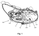
- the figure 1 represents a schematic view of a light device 100 of a motor vehicle not comprising a protective envelope as defined in the present invention.
- the light device 100 comprises a car projector housing 200 with an inner surface 201, and a bundle 10 of electrical cables positioned on the inner surface of the housing 200, said bundle 10 of electrical cables including electrical connectors 11. At least one of these electrical connectors 11 is intended to be connected to at least one light module (not shown).
- the bundle 10 of electrical cables is fixed on the inner surface 201 of the housing by means of holding means 202.
- the figure 2 represents a schematic view of an exoskeleton type protective envelope 20 according to the invention.
- This exoskeleton 20 is an electrically conductive polymeric envelope according to the invention, produced by molding or injection molding. It is intended to electrically and mechanically protect at least in part the bundle 10 of electrical cables positioned on the inner surface 201 of the housing, shown in FIG. figure 1 .
- the exoskeleton 20 is of uncrosslinked polymeric material and is electrically conductive. It can be obtained from an electrically conductive polymer composition marketed by the company Cool Polymers under the reference CoolPoly RS1595, based on polyamide (PA6).
- the exoskeleton 20 comprises at least a first opening 21 intended to let through at least one electrical connector 11 of the bundle of electric cables.
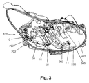
- the figure 3 represents a schematic view of the light device 100 of the figure 1 , further comprising the exoskeleton 20 of the figure 2 fixed on the inner surface 201 of the automobile projector housing.
- the exoskeleton 20 covers at least a longitudinal portion of the beam 10 of electric cables.
- At least one of the connectors 11 is positioned in the first opening 21 and holding means, such as for example screws 203, are inserted in the second openings 22 to fix the exoskeleton 20 on the inner surface 201 of the housing 200.
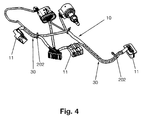
- the figure 4 is a schematic view of a bundle 10 of electrical cables comprising connectors 11, said bundle 10 being surrounded in part by a protective sheath type sheath 30 according to the invention.
- the bundle 10 of electrical cables is completely surrounded (in cross-section) by said sheath 30 on two longitudinal portions of the bundle 10 of electrical cables.
- This sheath 30 is an electrically conductive polymeric envelope according to the invention, made by extrusion. It is intended to electrically and mechanically protect at least part of the bundle 10 of electrical cables, said bundle being intended to be positioned on the inner surface of a housing for a car projector.
- the sheath 30 is made of uncrosslinked polymeric material and is electrically conductive. It can be obtained from an electrically conductive polymer composition marketed by the company Cool Polymers under the reference CoolPoly RS1595, based on polyamide (PA6).
- the sheath 30 can be held on the inner surface of a car projector housing by holding means 202, such as for example of the clamping collar type.
- the figure 5 represents a schematic view of a light device 101 of a motor vehicle comprising the bundle 10 of electric cables surrounded in part by the sheath 30, as shown in FIG. figure 4 .
- the bundle 10 of electrical cables surrounded in part by the sheath 30 is fixed to the inner surface 201 of the automobile headlight housing by means of a fastening means of the clamping collar type 202.
Abstract
La présente invention concerne un dispositif lumineux (100, 101) de véhicule automobile comprenant au moins un module lumineux et au moins un câble électrique (10), caractérisé en ce qu'au moins une portion longitudinale dudit câble électrique (10) est entourée au moins en partie ou complétement par au moins une enveloppe de protection (20, 30), l'enveloppe de protection étant une enveloppe polymérique électriquement conductrice.The present invention relates to a light device (100, 101) of a motor vehicle comprising at least one light module and at least one electric cable (10), characterized in that at least one longitudinal portion of said electric cable (10) is surrounded by at least partially or completely by at least one protective envelope (20, 30), the protective envelope being an electrically conductive polymeric envelope.
Description
La présente invention se rapporte à un dispositif lumineux de véhicule automobile comprenant au moins un câble électrique entouré au moins en partie par une enveloppe de protection électriquement conductrice en matériau polymère.The present invention relates to a light device of a motor vehicle comprising at least one electrical cable surrounded at least in part by an electrically conductive protective envelope of polymeric material.
Elle s'applique typiquement, mais non exclusivement, aux domaines des dispositifs d'éclairage et/ou de signalisation lumineuse de véhicule automobile.It applies typically, but not exclusively, to the fields of lighting devices and / or light signaling of a motor vehicle.
L'encombrement et la proximité des différents éléments tels que les modules code, les modules route ou encore les modules code additionnel, composant les projecteurs automobiles rendent difficile la mise en place de faisceaux de câbles électriques et leur fixation aux connecteurs électriques. En outre, parmi ces éléments, certains comme les ensembles de modules et la platine support sont en mouvement en configuration opérationnelle, ce qui peut entraîner un mauvais positionnement des faisceaux électriques, voire une dégradation de ceux-ci à force de frottements.The size and proximity of the various elements such as code modules, road modules or additional code modules, component automotive projectors make it difficult to install bundles of electrical cables and their attachment to electrical connectors. In addition, among these elements, some such as module assemblies and the support plate are moving in operational configuration, which can lead to poor positioning of the electrical beams, or even degradation thereof by friction.
Du document
Ceci étant, la mise en place ou le montage des faisceaux électriques au sein de cette gouttière n'est pas totalement satisfaisante car l'accès aux connecteurs électriques situés dans le boîtier reste difficile.This being the case, the installation or assembly of the electrical beams within this gutter is not entirely satisfactory because access to the electrical connectors located in the housing remains difficult.
En outre, les faisceaux électriques tels que disposés dans ces gouttières, lorsqu'ils sont soumis à une alimentation électriques, présentent l'inconvénient de générer des champs électromagnétiques influençant électro-magnétiquement les éléments électroniques internes et/ou externes au projecteur et ainsi d'altérer le fonctionnement des composants environnant à l'intérieur du boîtier pour projecteur automobile.In addition, the electrical bundles as arranged in these gutters, when subjected to an electrical supply, have the disadvantage of generating electromagnetic fields electromagnetically influencing the internal and / or external electronic elements of the projector and thus of impair the operation of the surrounding components inside the automotive headlight housing.
Le but de la présente invention est de pallier les inconvénients des techniques de l'art antérieur en proposant un dispositif lumineux de véhicule automobile comprenant au moins un câble électrique, limitant de façon significative les perturbations électriques et/ou électromagnétiques induites par le câble électrique lorsqu'il est soumis à une alimentation électrique, tout en permettant un positionnement et une connexion facilité dudit câble électrique au sein d'un boîtier pour dispositif lumineux, et notamment au sein d'un boîtier pour projecteur automobile.The object of the present invention is to overcome the disadvantages of the techniques of the prior art by providing a vehicle light device automobile comprising at least one electrical cable, significantly limiting the electrical and / or electromagnetic disturbances induced by the electric cable when it is subjected to a power supply, while allowing positioning and easy connection of said electric cable within a housing for a light device, and in particular within a housing for a car projector.
La présente invention a pour objet un dispositif lumineux de véhicule automobile comprenant au moins un module lumineux et au moins un câble électrique, caractérisé en ce qu'au moins une portion longitudinale dudit câble électrique est entourée au moins en partie ou complètement par au moins une enveloppe de protection, l'enveloppe de protection étant une enveloppe polymérique électriquement conductrice.The present invention relates to a light device of a motor vehicle comprising at least one light module and at least one electric cable, characterized in that at least a longitudinal portion of said electric cable is surrounded at least partially or completely by at least one protective envelope, the protective envelope being an electrically conductive polymeric envelope.
Grâce à l'invention, le ou les câbles électriques, notamment de type faisceaux électriques, protégé(s) par l'enveloppe de protection peuvent être facilement manipulés et positionnés dans un boîtier pour dispositif lumineux, et notamment dans un boîtier pour projecteur automobile. En outre, l'enveloppe de protection permet avantageusement de limiter de façon significative, voire d'éviter, les nuisances électromagnétiques, telles que notamment les nuisances électriques, entre le ou les câble(s) électrique(s) et leur environnement, et inversement.Thanks to the invention, the electric cable (s), in particular of the electric harness type, protected (s) by the protective envelope can be easily handled and positioned in a housing for light device, and in particular in a housing for automotive projector. In addition, the protective envelope advantageously makes it possible to significantly limit, or even to avoid, the electromagnetic nuisances, such as in particular the electrical nuisances, between the electric cable (s) and their environment, and vice versa. .
Dans la présente invention, on entend par « câble électrique » un ou plusieurs élément(s) électriquement conducteur(s) allongé(s) entouré(s) par au moins une couche électriquement isolante, la couche électriquement isolante pouvant être directement en contact physique avec le ou les éléments électriquement conducteur(s) allongé(s).In the present invention, the term "electrical cable" means one or more elongated electrically conductive element (s) surrounded (s) by at least one electrically insulating layer, the electrically insulating layer being able to be in direct physical contact. with the elongated electrically conductive element (s).
Le câble électrique comprend classiquement un axe longitudinal.The electric cable conventionally comprises a longitudinal axis.
L'élément électriquement conducteur allongé constitutif du câble électrique de l'invention est classiquement destiné à distribuer le courant électrique entre différents dispositifs électriques, notamment à distribuer le courant électrique à au moins un module lumineux de véhicule automobile. Plus particulièrement, le câble électrique de l'invention est destiné à être connecté, ou est connecté, à au moins un module lumineux de véhicule automobile.The elongate electrically conductive element constituting the electrical cable of the invention is conventionally intended to distribute the electric current between different electrical devices, in particular to distribute the electric current to at least one motor vehicle light module. More particularly, the electrical cable of the invention is intended to be connected to, or connected to, at least one motor vehicle light module.
L'élément électriquement conducteur allongé du câble électrique peut être typiquement un fil métallique ou une pluralité de fils métalliques, torsadé(s) ou non, notamment en cuivre et/ou en aluminium (au degré d'oxydation zéro), ou un de leurs alliages. De préférence, l'élément électriquement conducteur allongé du câble électrique est en cuivre (au degré d'oxydation zéro).The elongate electrically conductive element of the electrical cable may typically be a wire or a plurality of twisted or unreinforced wires, especially copper and / or aluminum (at the zero oxidation state), or one of their alloys. Preferably, the elongated electrically conductive member of the electrical cable is made of copper (at the zero oxidation state).
A titre d'exemple, le câble électrique peut comprendre un ou plusieurs fils électriques isolés, entouré(s) ou non par une gaine de protection.By way of example, the electric cable may comprise one or more insulated electrical wires, surrounded or not by a protective sheath.
Dans un mode de réalisation particulier, le dispositif lumineux de véhicule automobile peut comprendre au moins deux câbles électriques formant un ensemble de câbles électriques, au moins une portion longitudinale dudit ensemble étant entourée par ladite enveloppe de protection.In a particular embodiment, the light device of a motor vehicle may comprise at least two electrical cables forming a set of electric cables, at least a longitudinal portion of said assembly being surrounded by said protective envelope.
A titre d'exemple, ce peut être au moins deux fils conducteurs électriques isolés, ces deux fils conducteurs isolés étant entourés par l'enveloppe de protection.By way of example, it may be at least two insulated electrical conductors, these two insulated conductors being surrounded by the protective envelope.
Dans un autre mode de réalisation particulier, le dispositif lumineux de véhicule automobile peut comprendre au moins un faisceau de câbles électriques (i.e. faisceau électrique), au moins une portion longitudinale dudit faisceau étant entourée par ladite enveloppe de protection.In another particular embodiment, the light device of a motor vehicle may comprise at least one bundle of electric cables (i.e. electric beam), at least one longitudinal portion of said bundle being surrounded by said protective envelope.
De préférence, le dispositif lumineux de véhicule automobile peut comprendre au moins deux faisceaux de câbles électriques formant un ensemble de faisceaux, au moins une portion longitudinale dudit ensemble de faisceaux étant entourée par ladite enveloppe de protection.Preferably, the light device of a motor vehicle may comprise at least two bundles of electric cables forming a set of beams, at least a longitudinal portion of said set of bundles being surrounded by said protective envelope.
Dans le cadre de l'invention, le dispositif lumineux de véhicule automobile comprend en outre au moins un connecteur électrique. Ledit connecteur électrique est notamment destiné à pouvoir connecter le câble électrique à au moins un module lumineux.In the context of the invention, the light device of a motor vehicle further comprises at least one electrical connector. Said electrical connector is in particular intended to connect the electrical cable to at least one light module.
Le faisceau de câbles électriques mentionné dans la description peut être plus particulièrement un ensemble de plusieurs câbles électriques comprenant un ou plusieurs connecteurs électriques. Plus particulièrement, le faisceau de câbles électriques comprend plusieurs fils électriques isolés, qui sont notamment préassemblés, dotés d'un ou de plusieurs connecteurs électriques.The bundle of electrical cables mentioned in the description may be more particularly a set of several electrical cables comprising one or more electrical connectors. More particularly, the bundle of electrical cables comprises several insulated electrical wires, which are preassembled, with one or more electrical connectors.
Dans la présente invention, l'enveloppe de protection est une enveloppe entourant au moins en partie ou complètement au moins une portion longitudinale du ou des câbles électriques.In the present invention, the protective envelope is an envelope surrounding at least partially or completely at least a longitudinal portion of the electrical cable or cables.
Dans un premier mode de réalisation, l'enveloppe de protection est une enveloppe entourant au moins en partie, et de préférence non dans sa totalité, au moins une portion longitudinale du ou des câbles électriques.In a first embodiment, the protective envelope is a casing surrounding at least a portion, and preferably not in its entirety, at least a longitudinal portion of the electrical cable or cables.
En d'autres termes, l'enveloppe de protection est une enveloppe longitudinalement ouverte sur la portion du ou des câbles électriques à protéger. Plus particulièrement, l'enveloppe de protection a une surface ouverte en section transversale. On peut parler d'enveloppe de protection ouverte.In other words, the protective envelope is a longitudinally open envelope on the portion of the electrical cable or cables to be protected. More particularly, the protective envelope has an open cross-sectional area. We can talk about an open protection envelope.
L'enveloppe de protection ouverte est destinée à être associée à au moins une partie d'un boîtier pour dispositif lumineux, afin de former un ensemble fermé à l'intérieur duquel le ou les câbles électriques sont positionnés. L'enveloppe de protection ouverte forme ainsi avec la partie du boîtier avec laquelle elle est associée, un élément de protection entourant complètement dans sa section transversale au moins une portion longitudinale du ou des câbles électriques.The open protective envelope is intended to be associated with at least a portion of a light device housing, in order to form a closed assembly within which the electric cable or cables are positioned. The open protective envelope thus forms with the part of the housing with which it is associated, a protection element completely surrounding in its cross section at least a longitudinal portion of the electrical cable or cables.
L'enveloppe de protection ouverte peut être fixée sur la surface interne du boîtier pour dispositif lumineux, par tous moyens de maintien bien connus de l'homme du métier.The open protective envelope may be fixed on the inner surface of the luminous device housing, by any holding means well known to those skilled in the art.
De préférence, l'enveloppe de protection ouverte peut être du type exosquelette.Preferably, the open protective envelope may be of the exoskeleton type.
On entend par le terme « exosquelette » un élément extérieur (i.e. structurellement indépendant) audit(s) câble(s) électrique(s) de l'invention. L'exosquelette permet au moins en partie de supporter et de protéger mécaniquement ledit ou lesdits câble(s) électrique(s) de l'invention.The term "exoskeleton" is understood to mean an external element (ie structurally independent) to the electrical cable (s) of the invention. The exoskeleton allows at least partly to support and mechanically protect said electric cable (s) of the invention.
L'exosquelette peut avoir une épaisseur sensiblement constante autour du ou des câbles électriques qu'elle entoure en partie. A titre d'exemple, l'épaisseur de l'exosquelette est comprise entre 1 mm et 3,5 mm.The exoskeleton may have a substantially constant thickness around the electrical cable or cables that it partially surrounds. For example, the thickness of the exoskeleton is between 1 mm and 3.5 mm.
L'enveloppe de protection ouverte peut comprendre en outre au moins une première ouverture destinée à laisser passer au moins un connecteur électrique du câble électrique.The open protective envelope may further comprise at least a first opening for passing at least one electrical connector of the electrical cable.
L'enveloppe de protection ouverte peut comprendre en outre au moins une deuxième ouverture destinée à permettre la fixation de ladite enveloppe sur la surface interne d'un boîtier pour dispositif lumineux.The open protective envelope may further comprise at least a second opening intended to allow the attachment of said envelope to the inner surface of a luminous device housing.
Dans un deuxième mode de réalisation, l'enveloppe de protection est une enveloppe entourant complètement au moins une portion longitudinale du ou des câbles électriques.In a second embodiment, the protective envelope is an envelope completely surrounding at least one longitudinal portion of the electrical cable or cables.
En d'autres termes, l'enveloppe de protection est une enveloppe longitudinalement fermée sur la portion du ou des câbles électriques à protéger. Plus particulièrement, l'enveloppe de protection a une surface fermée en section transversale. On peut parler d'enveloppe de protection fermée.In other words, the protective envelope is a longitudinally enclosed envelope on the portion of the electrical cable or cables to be protected. More particularly, the protective envelope has a closed surface in cross section. We can talk about a closed protective envelope.
L'enveloppe de protection fermée peut être fixée sur la surface interne du boîtier pour dispositif lumineux, par tous moyens de maintien bien connus de l'homme du métier, tels que par exemple par vissage, collage ou bouterollage.The closed protective envelope may be fixed on the inner surface of the luminous device housing, by any holding means well known to those skilled in the art, such as for example by screwing, gluing or riveting.
De préférence, l'enveloppe de protection fermée peut être du type cylindrique, et peut avoir une épaisseur sensiblement constante tout autour du ou des câbles électriques. A titre d'exemple, l'épaisseur de la gaine est comprise entre 0,3 mm et 1,0 mm. L'enveloppe de protection peut ainsi être du type gaine de protection.Preferably, the closed protective envelope may be of the cylindrical type, and may have a substantially constant thickness all around the electrical cable or cables. By way of example, the thickness of the sheath is between 0.3 mm and 1.0 mm. The protective envelope can thus be of the protective sheath type.
Ainsi, l'enveloppe de protection selon l'invention est bien différente de la gouttière de l'art antérieur, cette dernière n'entourant pas complètement les câbles électriques puisque la gouttière est en forme de « U » et n'est donc pas une surface dite fermée.Thus, the protective envelope according to the invention is very different from the gutter of the prior art, the latter not completely surrounding the electric cables since the gutter is shaped "U" and is not a so-called closed surface.
Dans un troisième mode de réalisation, l'enveloppe de protection peut comprendre une enveloppe de protection selon le premier mode de réalisation et une enveloppe de protection selon le deuxième mode de réalisation.In a third embodiment, the protective envelope may comprise a protective envelope according to the first embodiment and a protective envelope according to the second embodiment.
L'enveloppe de protection selon l'invention, en plus de jouer un rôle de protection mécanique, permet avantageusement de former un blindage électromagnétique autour de la zone longitudinale du ou des câbles électriques qu'elle entoure en partie ou complètement.The protective envelope according to the invention, in addition to playing a role of mechanical protection, advantageously makes it possible to form an electromagnetic shielding around the longitudinal zone of the electrical cable or cables that it partially or completely surrounds.
Ce blindage électromagnétique permet avantageusement aux composants environnant le ou les câbles électriques, d'être protégés des champs électromagnétiques pouvant être générés par le ou les câbles électriques lorsqu'ils sont parcourus par un courant électrique. Il permet également, à l'inverse, aux câbles électriques protégés par l'enveloppe de protection, d'être préservés des champs électromagnétiques pouvant être générés par les composants électriques et et/ou magnétiques environnants parcourus par des courants électriques.This electromagnetic shield advantageously makes it possible for the components surrounding the electrical cable or cables to be protected from the electromagnetic fields that can be generated by the electric cable or cables when they are traversed by an electric current. It also allows, conversely, to the electrical cables protected by the protective envelope, to be preserved electromagnetic fields that can be generated by the electrical components and / or surrounding magnetic paths covered by electric currents.
La portion du ou des câbles électriques recouverte par l'enveloppe de protection a de préférence une longueur suffisante pour faire une barrière électromagnétique, notamment électrique, entre le ou les câbles électriques d'une part, et les composants environnant le ou les câbles électriques d'autre part, afin d'éviter les effets néfastes des champs électromagnétiques. En outre, les dimensions, et notamment la longueur et l'épaisseur, de l'enveloppe de protection peuvent aussi être ajustées pour optimiser la protection mécanique du ou des câbles électrique qu'elle entoure.The portion of the electrical cable or cables covered by the protective envelope is preferably of sufficient length to make an electromagnetic barrier, especially an electrical barrier, between the electrical cable or cables and the components surrounding the electrical cable or cables. on the other hand, to avoid the harmful effects of electromagnetic fields. In addition, the dimensions, and in particular the length and thickness, of the protective envelope can also be adjusted to optimize the mechanical protection of the electrical cable or cables that surround it.
Dans un mode de réalisation particulier, l'enveloppe de protection de l'invention s'étend longitudinalement sur toute la longueur du ou des câbles électriques à protéger.In a particular embodiment, the protective envelope of the invention extends longitudinally over the entire length of the electrical cable or cables to be protected.
L'enveloppe de protection permet en outre de maintenir ensemble, et de façon continue sur la zone à protéger, plusieurs câbles électriques. De ce fait, la manipulation et l'installation de l'ensemble de câbles entouré par l'enveloppe de protection s'en trouvent grandement facilité. En outre, la fixation du ou des câbles électriques entourés par l'enveloppe de protection de l'invention sur la surface intérieure d'un boîtier pour dispositif lumineux est optimisée.The protective envelope also allows to maintain together, and continuously on the area to be protected, several electrical cables. As a result, the manipulation and installation of the cable assembly surrounded by the protective envelope is greatly facilitated. In addition, the fixing of the electrical cable or cables surrounded by the protective envelope of the invention on the inner surface of a light device housing is optimized.
Dans un mode de réalisation particulier, l'enveloppe de protection est une enveloppe dite souple, par opposition à la gouttière de l'art antérieur qui est rigide.In a particular embodiment, the protective envelope is a so-called flexible envelope, as opposed to the gutter of the prior art which is rigid.
La souplesse induite par l'enveloppe de protection permet avantageusement de faciliter son positionnement à l'intérieur d'un boîtier pour dispositif lumineux.The flexibility induced by the protective envelope advantageously facilitates its positioning inside a housing for light device.
L'enveloppe de protection de l'invention est plus particulièrement une enveloppe électriquement conductrice de type polymérique.The protective envelope of the invention is more particularly an electrically conductive envelope of polymeric type.
Dans la présente invention, on entend par l'expression « électriquement conducteur » ou « électriquement conductrice » une conductivité électrique d'au moins 1.10-8 S/m (siemens par mètre), de préférence d'au moins 1.10-6 S/m, et de préférence d'au moins 1.10-3 S/m, et de préférence d'au plus 1.103 S/m (à 25°C).In the present invention, the expression "electrically conductive" or "electrically conductive" means an electrical conductivity of at least 1.10 -8 S / m (siemens per meter), preferably at least 1.10 -6 S / m. m, and preferably at least 1.10 -3 S / m, and preferably at most 1.10 3 S / m (at 25 ° C).
Le dispositif lumineux de l'invention peut comprendre une ou plusieurs enveloppe(s) de protection selon l'invention. Lorsque le dispositif lumineux comprend au moins deux enveloppes de protection selon l'invention, la conductivité électrique de chaque enveloppe peut être différente.The light device of the invention may comprise one or more protective envelope (s) according to the invention. When the light device comprises at least two protective envelopes according to the invention, the electrical conductivity of each envelope may be different.
La conductivité électrique de l'enveloppe de protection selon l'invention peut facilement être déterminée à l'aide d'un appareil permettant la mesure de conductivité électrique, tel que par exemple un appareil référencé AUTOSIGMA 3000, commercialisé par la société Sofranel.The electrical conductivity of the protective envelope according to the invention can easily be determined with the aid of an apparatus for measuring electrical conductivity, such as, for example, a device referenced AUTOSIGMA 3000, marketed by Sofranel.
L'enveloppe de protection peut être obtenue à partir d'une composition polymère comprenant au moins un polymère.The protective envelope can be obtained from a polymer composition comprising at least one polymer.
La composition polymère de l'invention peut comprendre un ou plusieurs polymère(s), le terme « polymère » pouvant s'entendre par tout type de polymère bien connu de l'homme du métier tel que homopolymère ou copolymère (e.g. copolymère séquencé, copolymère statistique, terpolymère, etc...).The polymer composition of the invention may comprise one or more polymers, the term "polymer" being understood by any type of polymer well known to those skilled in the art such as homopolymer or copolymer (eg block copolymer, copolymer statistical, terpolymer, etc ...).
Le polymère peut être du type thermoplastique ou élastomère, et peut être réticulé ou non, la réticulation étant réalisée par des techniques bien connues de l'homme du métier, telles que par exemple la réticulation peroxyde, la réticulation silane, la réticulation ultra-violet.The polymer may be of the thermoplastic or elastomer type, and may be cross-linked or not, the crosslinking being carried out by well-known techniques. known to those skilled in the art, such as, for example, peroxide crosslinking, silane crosslinking, ultraviolet crosslinking.
Selon une première variante, l'enveloppe de protection de l'invention peut être un matériau non réticulé, notamment du type thermoplastique ou élastomère.According to a first variant, the protective envelope of the invention may be a non-crosslinked material, in particular of the thermoplastic or elastomer type.
Selon une deuxième variante, elle peut être un matériau réticulé, par des techniques bien connues de l'homme du métier.According to a second variant, it may be a crosslinked material, by techniques well known to those skilled in the art.
Les propriétés électriques (i.e. conductivité électrique) de l'enveloppe de protection polymérique peuvent être obtenues selon des modes de réalisation différents.The electrical properties (i.e. electrical conductivity) of the polymeric shield can be obtained in different embodiments.
Selon un premier mode de réalisation, l'enveloppe de protection peut être obtenue à partir d'une composition polymère comprenant au moins un polymère électriquement conducteur, et optionnellement au moins une charge.According to a first embodiment, the protective envelope can be obtained from a polymer composition comprising at least one electrically conductive polymer, and optionally at least one charge.
Selon une première variante, les polymères électriquement conducteurs de l'invention peuvent être composés typiquement de macromolécules comprenant des liaisons π délocalisées au moins sur une partie ou sur tout le long de leurs chaines macromoléculaires (i.e. chaines principales ou « backbone chains » en anglais).According to a first variant, the electrically conductive polymers of the invention may be typically composed of macromolecules comprising delocalized π-bonds at least on part or all along their macromolecular chains (ie main chains or "backbone chains"). .
De préférence, les liaisons π délocalisées peuvent être du type π -σ- π, alternant des liaisons covalentes simples et multiples. Par exemple, on peut citer le système des doubles liaisons conjuguées, comme par exemple « -C=C-C=C- ».Preferably, the delocalized π bonds may be of the π -σ-π type, alternating single and multiple covalent bonds. For example, mention may be made of the conjugated double bond system, for example "-C = C-C = C-".
Selon une deuxième variante, la conductivité électrique des polymères électriquement conducteurs de l'invention peut résulter en ce que leurs chaînes macromoléculaires acquièrent des charges positives ou négatives à travers l'oxydation ou la réduction de donneurs ou d'accepteurs d'électrons, pouvant être par exemple des éléments dopants.According to a second variant, the electrical conductivity of the electrically conductive polymers of the invention may result in their macromolecular chains acquiring positive or negative charges through the oxidation or reduction of electron donors or acceptors, which can be for example doping elements.
Selon une troisième variante, la conductivité électrique des polymères électriquement conducteurs de l'invention peut résulter en ce que la charge citée ci-avant est transportée par dissolution des ions.According to a third variant, the electrical conductivity of the electrically conductive polymers of the invention may result in that the charge mentioned above is transported by dissolving the ions.
A titre d'exemple dans ce premier mode de réalisation, le polymère électriquement conducteur peut être choisi parmi les polyanilines, de préférence sous la forme d'éméraldine ; les polythiophènes ; les polypyrroles ; les polyacéthylènes ; et un de leurs mélanges. Comme référence commerciale, on peut citer la référence Panipol de la société Panipol Ltd, qui comprend une polyaniline; la référence Baytron P de la société Clevios, qui comprend un polythiophène et plus particulièrement un poly(3,4-éthylènedioxythiophène)-poly(styrène sulfonate) (PEDOT:PSS); ou la référence commerciale Conquest de la société Sigma-Aldrich, qui comprend un polypyrrole.By way of example in this first embodiment, the electrically conductive polymer may be chosen from polyanilines, preferably in the form of emeraldine; polythiophenes; polypyrroles; polyacetylenes; and one of their mixtures. As a commercial reference, mention may be made of the Panipol reference from Panipol Ltd, which comprises a polyaniline; the Baytron P reference from Clevios, which comprises a polythiophene and more particularly a poly (3,4-ethylenedioxythiophene) -poly (styrene sulfonate) (PEDOT: PSS); or the Conquest commercial reference of Sigma-Aldrich, which comprises a polypyrrole.
La charge optionnelle peut être tout type de charge bien connue de l'homme du métier, du type minérale ou organique.The optional filler can be any type of filler well known to those skilled in the art, of the mineral or organic type.
La charge optionnelle peut être électriquement conductrice ou non.The optional charge may be electrically conductive or not.
La charge électriquement conductrice peut être choisie notamment parmi :
- des charges carbonées, telles que par exemple du noir de carbone, du graphite, du graphène, un polymorphe du carbone (e.g. diamant) ;
- des charges métalliques, telles que de l'aluminium, du magnésium, de l'argent, de l'or, du cuivre ;
- des métaux composites, tels que AlSiC (matrice aluminium comprenant des particules de carbure de silicium) ;
- des oxydes métalliques simples ou complexes, tels que Al2O3, Fe2O3, MgAl2O4, CoFe2O4, BaTiO3, TiO2 ;
- des nitrures métalliques ou de métalloïdes, tels que par exemple du nitrure de bore, du nitrure d'aluminium ; et
- un de leurs mélanges.
- carbonaceous fillers, such as, for example, carbon black, graphite, graphene, a carbon polymorph (eg diamond);
- metal fillers, such as aluminum, magnesium, silver, gold, copper;
- composite metals, such as AlSiC (aluminum matrix comprising silicon carbide particles);
- simple or complex metal oxides, such as Al 2 O 3 , Fe 2 O 3 , MgAl 2 O 4 , CoFe 2 O 4 , BaTiO 3 , TiO 2 ;
- metal nitrides or metalloids, such as, for example, boron nitride, aluminum nitride; and
- one of their mixtures.
Le polymère électriquement conducteur pourra être introduit dans la composition polymère en une quantité suffisante pour rendre la composition électriquement conductrice.The electrically conductive polymer may be introduced into the polymer composition in an amount sufficient to render the composition electrically conductive.
Selon un deuxième mode de réalisation, l'enveloppe de protection peut être obtenue à partir d'une composition polymère comprenant au moins un polymère et au moins une charge électriquement conductrice.According to a second embodiment, the protective envelope can be obtained from a polymer composition comprising at least one polymer and at least one electrically conductive filler.
Le polymère peut être tout type de polymère bien connu de l'homme du métier, du type organique tel que par exemple des polyoléfines, des polycarbonates, des polyamides ; ou inorganique tel que par exemple des polyorganosiloxanes.The polymer may be any type of polymer well known to those skilled in the art, of the organic type such as, for example, polyolefins, polycarbonates, polyamides; or inorganic such as for example polyorganosiloxanes.
Le polymère peut être un polymère électriquement conducteur ou non.The polymer may be an electrically conductive polymer or not.
Plus particulièrement, le polymère peut être un polymère d'oléfine (i.e. polyoléfine), et de préférence un polymère d'éthylène et/ou de propylène. Un polymère d'oléfine est classiquement un polymère obtenu à partir d'au moins un monomère d'oléfine. A titre d'exemple, le polymère peut être choisi parmi un homopolymère d'éthylène, des copolymères d'éthylènes, et un de leurs mélanges.More particularly, the polymer may be an olefin polymer (i.e., polyolefin), and preferably a polymer of ethylene and / or propylene. An olefin polymer is conventionally a polymer obtained from at least one olefin monomer. By way of example, the polymer may be chosen from an ethylene homopolymer, copolymers of ethenes, and a mixture thereof.
La charge électriquement conductrice peut être tout type de charge bien connue de l'homme du métier, du type minérale ou organique.The electrically conductive filler may be any type of filler well known to those skilled in the art, of the mineral or organic type.
La charge électriquement conductrice peut être choisie notamment parmi :
- des charges carbonées, telles que par exemple du noir de carbone, du graphite, du graphène, un polymorphe du carbone ;
- des charges métalliques, telles que de l'aluminium, du magnésium, de l'argent, de l'or, du cuivre ;
- des métaux composites, tels que AlSiC (matrice aluminium comprenant des particules de carbure de silicium) ;
- des oxydes métalliques simples ou complexes, tels que Al2O3, Fe2O3, MgAl2O4, CoFe2O4, BaTiO3, TiO2 ;
- des nitrures métalliques ou de métalloïdes de bore, tels que par exemple du nitrure de bore, du nitrure d'aluminium ; et
- un de leurs mélanges.
- carbonaceous fillers, such as, for example, carbon black, graphite, graphene, a carbon polymorph;
- metal fillers, such as aluminum, magnesium, silver, gold, copper;
- composite metals, such as AlSiC (aluminum matrix comprising silicon carbide particles);
- simple or complex metal oxides, such as Al 2 O 3 , Fe 2 O 3 , MgAl 2 O 4 , CoFe 2 O 4 , BaTiO 3 , TiO 2 ;
- metal nitrides or boron metalloids, such as, for example, boron nitride, aluminum nitride; and
- one of their mixtures.
La charge électriquement conductrice pourra être introduite dans la composition polymère en une quantité suffisante pour rendre la composition électriquement conductrice, cette quantité pouvant notamment varier selon le type et la morphologie de charge électriquement conductrice sélectionnée.The electrically conductive filler may be introduced into the polymer composition in an amount sufficient to render the composition electrically conductive, this quantity may in particular vary according to the type and the morphology of the selected electrically conductive filler.
A titre d'exemple dans ce deuxième mode de réalisation, on peut citer comme composition polymère comprenant au moins un polymère et au moins une charge électriquement conductrice, les produits électriquement conducteurs de la société Cool Polymers ou Celanese, tels que par exemple la référence commerciale CoolPoly RS1595, à base de polyamide (PA 6).By way of example in this second embodiment, mention may be made, as a polymer composition comprising at least one polymer and at least one electrically conductive filler, the electrically conductive products of the company Cool Polymers or Celanese, such as, for example, the commercial reference. CoolPoly RS1595, based on polyamide (PA 6).
Selon un troisième mode de réalisation, l'enveloppe de protection peut être obtenue à partir d'une composition polymère comprenant au moins un polymère électriquement conducteur et au moins une charge électriquement conductrice, le polymère électriquement conducteur et la charge électriquement conductrice étant tels que définis dans le premier et le deuxième modes de réalisation.According to a third embodiment, the protective envelope can be obtained from a polymer composition comprising at least one electrically conductive polymer and at least one electrically charged charge. conductive, the electrically conductive polymer and the electrically conductive filler being as defined in the first and second embodiments.
Le polymère électriquement conducteur et la charge électriquement conductrice pourront être introduits dans la composition polymère en une quantité suffisante pour rendre la composition électriquement conductrice.The electrically conductive polymer and the electrically conductive filler may be introduced into the polymer composition in an amount sufficient to render the composition electrically conductive.
Dans un mode de réalisation particulier, la composition polymère de l'invention peut comprendre au moins 30 % en volume de polymère(s), et de préférence au moins 50 % en volume de polymère(s), par rapport au volume total de la composition polymère.In a particular embodiment, the polymer composition of the invention may comprise at least 30% by volume of polymer (s), and preferably at least 50% by volume of polymer (s), relative to the total volume of the polymer. polymeric composition.
Elle peut également comprendre au plus 95 % en volume de polymère(s), et de préférence au plus 80% en volume de polymère(s), par rapport au volume total de la composition polymère.It may also comprise at most 95% by volume of polymer (s), and preferably at most 80% by volume of polymer (s), relative to the total volume of the polymer composition.
La quantité en volume de polymère(s) dans la composition polymère représente la quantité totale de l'ensemble des polymères constitutifs de la composition polymère, que ces polymères soient électriquement conducteurs ou non.The quantity by volume of polymer (s) in the polymer composition represents the total amount of all the polymers constituting the polymer composition, whether these polymers are electrically conductive or not.
Par ailleurs, la composition polymère de l'invention peut comprendre au moins 5 % en volume de charge(s), et de préférence au moins 20% en volume de charge(s), par rapport au volume total de la composition polymère.Furthermore, the polymer composition of the invention may comprise at least 5% by volume of filler (s), and preferably at least 20% by volume of filler (s), relative to the total volume of the polymer composition.
Elle peut également comprendre au plus 70 % en volume de charge(s), et de préférence au plus 50% en volume de charge(s), par rapport au volume total de la composition polymère.It may also comprise at most 70% by volume of filler (s), and preferably at most 50% by volume of filler (s), relative to the total volume of the polymer composition.
La quantité en volume de charge(s) dans la composition polymère, lorsque la composition polymère comprend au moins une charge, représente la quantité totale de l'ensemble des charges constitutives de la composition polymère, que ces charges soient électriquement conductrices ou non.The amount by volume of filler (s) in the polymer composition, when the polymer composition comprises at least one filler, represents the total amount of all the constitutive fillers of the polymer composition, whether these fillers are electrically conductive or not.
De préférence, la composition polymère de l'invention comprend au moins 95% en volume de polymère(s), ou au moins 95% en volume de polymère(s) et de charge(s), par rapport au volume total de la composition polymère.Preferably, the polymer composition of the invention comprises at least 95% by volume of polymer (s), or at least 95% by volume of polymer (s) and filler (s), relative to the total volume of the composition polymer.
La composition polymère de l'invention peut typiquement comprendre en outre des additifs en une quantité de 0,01 à 10 % en volume (inclusivement) par rapport au volume total de la composition polymère.The polymer composition of the invention may typically additionally comprise additives in an amount of from 0.01 to 10% by volume (inclusive) based on the total volume of the polymeric composition.
Les additifs sont bien connus de l'homme du métier et peuvent être par exemple choisis parmi :
- des agents de protection tels que des antioxydants ;
- des agents de mise en oeuvre, tels que des plastifiants, des lubrifiants, des huiles ;
- des agents de réticulation, tels que par exemple des peroxydes organiques ; et
- un de leurs mélanges.
- protective agents such as antioxidants;
- processors, such as plasticizers, lubricants, oils;
- crosslinking agents, such as, for example, organic peroxides; and
- one of their mixtures.
L'enveloppe de protection étant à base d'un matériau polymère, tout type de procédé bien connu de l'homme du métier dans le domaine de la formulation et de la mise en forme des polymères peut être utilisé.Since the protective envelope is based on a polymeric material, any type of process well known to those skilled in the field of polymer formulation and shaping may be used.
A titre d'exemple de procédé de fabrication, on peut citer l'injection, le moulage, l'injection-moulage, le thermoformage ou l'extrusion.As an example of a manufacturing process, mention may be made of injection, molding, injection-molding, thermoforming or extrusion.
Selon le premier mode de réalisation mentionné ci-avant, le procédé de fabrication préféré de l'invention est le moulage, l'injection-moulage ou le thermoformage, afin de pouvoir former facilement une enveloppe sous forme d'exosquelette.According to the first embodiment mentioned above, the preferred manufacturing method of the invention is molding, injection-molding or thermoforming, in order to easily form an envelope in the form of an exoskeleton.
Selon le deuxième mode de réalisation mentionné ci-avant, le procédé de fabrication préféré de l'invention est l'extrusion, afin de pouvoir former facilement une enveloppe sous forme de couche ou de gaine extrudée autour du ou des câbles électriques.According to the second embodiment mentioned above, the preferred manufacturing method of the invention is extrusion, in order to easily form an envelope in the form of a layer or sheath extruded around the electrical cables or cables.
Lorsque la composition polymère de l'invention comprend au moins une charge, ladite charge est de préférence incorporée dans le polymère à l'état malléable ou fondu afin d'obtenir un mélange final homogène entre le polymère et la charge.When the polymer composition of the invention comprises at least one filler, said filler is preferably incorporated into the polymer in the malleable or molten state in order to obtain a homogeneous final blend between the polymer and the filler.
Lorsque la composition polymère comprend un agent de réticulation, tel que par exemple un peroxyde organique, afin d'obtenir une enveloppe de protection dite réticulée, l'agent de réticulation est mélangé tout d'abord à la composition polymère à une température suffisante pour rendre le polymère malléable ou en fusion mais inférieure à la température de décomposition dudit peroxyde organique. Puis, une fois la composition mise en forme, elle peut être réticulée à une température suffisante pour déclencher la décomposition du peroxyde et ainsi permettre la réticulation de la composition polymère.When the polymer composition comprises a crosslinking agent, such as for example an organic peroxide, in order to obtain an envelope of so-called crosslinked protection, the crosslinking agent is first mixed with the polymer composition at a temperature sufficient to make the polymer malleable or melt but less than the decomposition temperature of said organic peroxide. Then, once the composition is shaped, it can be crosslinked at a temperature sufficient to trigger the decomposition of the peroxide and thus allow the crosslinking of the polymer composition.
La présente invention s'applique de préférence aux domaines des dispositifs lumineux de véhicule automobile.The present invention applies preferably to the fields of light devices of a motor vehicle.
Plus particulièrement, le dispositif lumineux de véhicule automobile peut être un dispositif d'éclairage et/ou de signalisation lumineuse. A titre d'exemple, le dispositif d'éclairage peut être un projecteur avant de véhicule automobile ou un dispositif d'éclairage intérieur de véhicule automobile, et le dispositif de signalisation lumineuse peut être un feu arrière de véhicule automobile. De façon plus particulière, on peut également citer comme exemple de dispositif lumineux un feu de route, un feu de croisement, un feu de signalisation diurne, une lanterne, un feu stop, un indicateur de direction, un feu antibrouillard, etc.More particularly, the light device of a motor vehicle may be a lighting device and / or a light signaling device. For example, the lighting device may be a front projector of a motor vehicle or an interior lighting device of a motor vehicle, and the light signaling device may be a rear light of a motor vehicle. More particularly, there may also be mentioned as an example of a light device a driving light, a dipped beam, a daytime running lamp, a lantern, a stop light, a direction indicator, a fog lamp, etc.
Le dispositif lumineux de véhicule automobile peut comprendre au moins un module lumineux.The light device of a motor vehicle may comprise at least one light module.
Plus particulièrement, ledit module lumineux est apte à émettre un faisceau lumineux, et peut être une unité d'éclairage comprenant au moins une source lumineuse. La source lumineuse peut comprendre une ou plusieurs élément(s) photoémissive(s) à semi-conducteur.More particularly, said light module is capable of emitting a light beam, and may be a lighting unit comprising at least one light source. The light source may include one or more light emitting element (s) semiconductor.
Dans un mode de réalisation particulier, le module lumineux est apte à émettre un faisceau lumineux pour réaliser tout ou partie d'une fonction d'éclairage et/ou de signalisation lumineuse, pour véhicule automobile.In a particular embodiment, the light module is able to emit a light beam to perform all or part of a lighting function and / or light signaling, for a motor vehicle.
Le module lumineux peut en outre comprendre un dissipateur thermique, tel qu'un radiateur, et une carte de circuit imprimé, notamment du type PCB (« Printed Circuit Board »), et/ou une carte de circuit imprimé flexible, notamment du type FPCB (« Flexible Printed Circuit Board »), et/ou un dispositif d'interconnexion à géométrie variable, notamment du type MID (« Molded In Device »), ces types de configuration étant bien connue de l'homme du métier.The light module may further comprise a heat sink, such as a radiator, and a printed circuit board, in particular of the PCB (" Printed Circuit Board ") type, and / or a flexible printed circuit board, in particular of the FPCB type. (" Flexible Printed Circuit Board "), and / or an interconnection device with variable geometry, in particular of the MID type ("Molded In Device "), these types of configuration being well known to those skilled in the art.
Le module lumineux du dispositif lumineux selon l'invention est destiné à être connecté, ou est connecté, à au moins un câble électrique conforme à l'invention. La connexion peut être réalisée classiquement par l'intermédiaire d'au moins un connecteur électrique.The light module of the light device according to the invention is intended to be connected to, or connected to, at least one electric cable according to the invention. The connection can be made conventionally via at least one electrical connector.
Le dispositif lumineux selon l'invention peut comprendre en outre un boîtier pour dispositif lumineux, et notamment pour projecteur automobile, avec une surface interne, et au moins un moyen de maintien de l'enveloppe de protection sur la surface interne dudit boîtier. Ledit boîtier permet de recevoir ledit câble électrique entouré par son enveloppe de protection.The light device according to the invention may further comprise a light device housing, and in particular for a motor vehicle headlamp, with an internal surface, and at least one means for holding the protective envelope on the inner surface of said housing. Said housing makes it possible to receive said electric cable surrounded by its protective envelope.
Le moyen de maintien peut être par exemple un collier de serrage, un clip ou une vis.The holding means may be for example a clamp, a clip or a screw.
D'autres caractéristiques et avantages de la présente invention apparaîtront à la lumière de la description d'exemples non limitatifs de dispositifs lumineux selon l'invention, faits en référence aux figures.
- La
figure 1 représente une vue d'ensemble d'un dispositif lumineux de véhicule automobile, sans enveloppe de protection. - La
figure 2 représente une vue schématique d'une enveloppe de protection du type exosquelette selon l'invention. - La
figure 3 représente une vue d'ensemble d'un dispositif lumineux de véhicule automobile selon lafigure 1 comprenant l'enveloppe de protection de lafigure 2 . - La
figure 4 représente une vue schématique d'un faisceau de câbles électriques entouré en partie par une enveloppe de protection du type gaine selon l'invention. - La
figure 5 représente une vue d'ensemble d'un dispositif lumineux de véhicule automobile comprenant le faisceau de câbles électriques entouré en partie par une enveloppe de protection du type gaine de lafigure 4 .
- The
figure 1 represents an overview of a light device of a motor vehicle, without protective envelope. - The
figure 2 represents a schematic view of a protective envelope of the exoskeleton type according to the invention. - The
figure 3 represents an overview of a light device of a motor vehicle according to thefigure 1 including the protective envelope of thefigure 2 . - The
figure 4 is a schematic view of a bundle of electrical cables surrounded in part by a sheath type of protective envelope according to the invention. - The
figure 5 represents an overview of a motor vehicle light device comprising the electrical cable bundle partially surrounded by a sheath-type protective envelope of thefigure 4 .
Pour des raisons de clarté, seuls les éléments essentiels pour la compréhension de l'invention ont été représentés de manière schématique, et ceci sans respect de l'échelle.For the sake of clarity, only the essential elements for understanding the invention have been shown schematically, and this without respect of the scale.
La
Le dispositif lumineux 100 comprend un boîtier 200 pour projecteur automobile avec une surface interne 201, et un faisceau 10 de câbles électriques positionné sur la surface interne du boîtier 200, ledit faisceau 10 de câbles électriques comprenant des connecteurs électriques 11. Au moins un de ces connecteurs électriques 11 est destiné à être connecté à au moins un module lumineux (non représenté).The
Le faisceau 10 de câbles électriques est fixé sur la surface interne 201 du boîtier à l'aide de moyens de maintien 202.The
La
Cet exosquelette 20 est une enveloppe polymérique électriquement conductrice conforme à l'invention, réalisée par moulage ou injection moulage. Il est destiné à protéger électriquement et mécaniquement au moins en partie le faisceau 10 de câbles électriques positionné sur la surface interne 201 du boîtier, représenté sur la
L'exosquelette 20 est en matériau polymère non réticulé et est électriquement conducteur. Il peut être obtenu à partir d'une composition polymère électriquement conductrice, commercialisée par la société Cool Polymers sous la référence CoolPoly RS1595, à base de polyamide (PA6).The
L'exosquelette 20 comprend au moins une première ouverture 21 destinée à laisser passer au moins un connecteur électrique 11 du faisceau de câbles électriques.The
Il comprend en outre des deuxièmes ouvertures 22 destinées à permettre la fixation dudit exosquelette sur la surface interne 201 du boîtier 200 pour dispositif lumineux, et ainsi former une enveloppe fermée autour du faisceau 10 de câbles électriques.It further comprises
La
Au moins un des connecteurs 11 est positionné dans la première ouverture 21 et des moyens de maintien, tels que par exemple des vis 203, sont insérés dans les deuxièmes ouvertures 22 pour fixer l'exosquelette 20 sur la surface interne 201 du boîtier 200.At least one of the
La
Le faisceau 10 de câbles électriques est entouré complètement (en section transversale) par ladite gaine 30 sur deux portions longitudinales du faisceau 10 de câbles électriques.The
Cette gaine 30 est une enveloppe polymérique électriquement conductrice conforme à l'invention, réalisée par extrusion. Elle est destinée à protéger électriquement et mécaniquement au moins en partie le faisceau 10 de câbles électriques, ledit faisceau étant destiné à être positionné sur la surface interne d'un boîtier pour projecteur automobile.This
La gaine 30 est en matériau polymère non réticulé et est électriquement conductrice. Elle peut être obtenue à partir d'une composition polymère électriquement conductrice, commercialisée par la société Cool Polymers sous la référence CoolPoly RS1595, à base de polyamide (PA6).The
La gaine 30 peut être maintenue sur la surface interne d'un boîtier pour projecteur automobile par des moyens de maintien 202, tel que par exemple du type collier de serrage.The
La
Le faisceau 10 de câbles électriques entouré en partie par la gaine 30 est fixé sur la surface interne 201 du boîtier pour projecteur automobile, à l'aide d'un moyen de maintien du type collier de serrage 202.The
Claims (13)
Applications Claiming Priority (1)
| Application Number | Priority Date | Filing Date | Title |
|---|---|---|---|
| FR1555681A FR3037636A1 (en) | 2015-06-22 | 2015-06-22 | POLYMERIC PROTECTION ENVELOPE FOR ELECTRICAL BEAMS IN A LIGHTING DEVICE OF A MOTOR VEHICLE |
Publications (1)
| Publication Number | Publication Date |
|---|---|
| EP3109537A1 true EP3109537A1 (en) | 2016-12-28 |
Family
ID=54366304
Family Applications (1)
| Application Number | Title | Priority Date | Filing Date |
|---|---|---|---|
| EP16174439.6A Withdrawn EP3109537A1 (en) | 2015-06-22 | 2016-06-14 | Polymeric protective cover for electrical beams in a light device of a motor vehicle |
Country Status (3)
| Country | Link |
|---|---|
| US (1) | US20160372233A1 (en) |
| EP (1) | EP3109537A1 (en) |
| FR (1) | FR3037636A1 (en) |
Cited By (4)
| Publication number | Priority date | Publication date | Assignee | Title |
|---|---|---|---|---|
| EP3421872A1 (en) * | 2017-06-29 | 2019-01-02 | Valeo Vision Belgique | Lighting device for a motor vehicle comprising a guided wiring harness |
| FR3127551A1 (en) * | 2021-09-30 | 2023-03-31 | Valeo Vision | LIGHTING MODULE FOR A VEHICLE HEADLIGHT OF A MOTOR VEHICLE |
| FR3134442A1 (en) * | 2022-04-11 | 2023-10-13 | Psa Automobiles Sa | Headlight for motor vehicles fitted with a bezel with anti-vibration security elements |
| FR3134876A1 (en) * | 2022-04-26 | 2023-10-27 | Psa Automobiles Sa | Vehicle headlight projector |
Families Citing this family (3)
| Publication number | Priority date | Publication date | Assignee | Title |
|---|---|---|---|---|
| FR3039474B1 (en) * | 2015-07-31 | 2021-02-19 | Valeo Iluminacion Sa | DEVICE FOR CLOSING A VEHICLE OPTICAL BOX OPENING, OPTICAL BOX EQUIPPED WITH SUCH A DEVICE AND CORD FOR SUCH DEVICE |
| JP7285687B2 (en) * | 2018-10-02 | 2023-06-02 | 株式会社小糸製作所 | VEHICLE LAMP AND METHOD FOR MANUFACTURING VEHICLE LAMP |
| FR3128914B1 (en) * | 2021-11-09 | 2024-01-05 | Valeo Vision | Automotive lighting device |
Citations (4)
| Publication number | Priority date | Publication date | Assignee | Title |
|---|---|---|---|---|
| US20020155738A1 (en) * | 2000-08-18 | 2002-10-24 | Takashi Ohsawa | Shield cable method of manufacturing shield cable, and discharge lamp lighting device using shield cable |
| EP2266845A1 (en) | 2009-06-22 | 2010-12-29 | Automotive Lighting Reutlingen GmbH | Method for laying and device for guiding and fixing cables of a harness in the interior of a housing of a lighting device of a motor vehicle |
| DE102011117085A1 (en) * | 2011-10-27 | 2013-05-02 | Md Elektronik Gmbh | On-board network component for a data transmission system in a motor vehicle |
| FR2990047A1 (en) * | 2012-04-27 | 2013-11-01 | Nexans | High voltage electrical transmission cable comprises semiconductive polymeric element that surrounds electrically conductive element in cross section, reduces corona effect along cable and has constant thickness around conductive element |
-
2015
- 2015-06-22 FR FR1555681A patent/FR3037636A1/en active Pending
-
2016
- 2016-06-14 EP EP16174439.6A patent/EP3109537A1/en not_active Withdrawn
- 2016-06-14 US US15/181,623 patent/US20160372233A1/en not_active Abandoned
Patent Citations (4)
| Publication number | Priority date | Publication date | Assignee | Title |
|---|---|---|---|---|
| US20020155738A1 (en) * | 2000-08-18 | 2002-10-24 | Takashi Ohsawa | Shield cable method of manufacturing shield cable, and discharge lamp lighting device using shield cable |
| EP2266845A1 (en) | 2009-06-22 | 2010-12-29 | Automotive Lighting Reutlingen GmbH | Method for laying and device for guiding and fixing cables of a harness in the interior of a housing of a lighting device of a motor vehicle |
| DE102011117085A1 (en) * | 2011-10-27 | 2013-05-02 | Md Elektronik Gmbh | On-board network component for a data transmission system in a motor vehicle |
| FR2990047A1 (en) * | 2012-04-27 | 2013-11-01 | Nexans | High voltage electrical transmission cable comprises semiconductive polymeric element that surrounds electrically conductive element in cross section, reduces corona effect along cable and has constant thickness around conductive element |
Cited By (8)
| Publication number | Priority date | Publication date | Assignee | Title |
|---|---|---|---|---|
| EP3421872A1 (en) * | 2017-06-29 | 2019-01-02 | Valeo Vision Belgique | Lighting device for a motor vehicle comprising a guided wiring harness |
| FR3068313A1 (en) * | 2017-06-29 | 2019-01-04 | Valeo Vision Belgique | LIGHTING DEVICE FOR A MOTOR VEHICLE WITH A GUIDE ELECTRIC BEAM |
| US10520154B2 (en) | 2017-06-29 | 2019-12-31 | Valeo Vision Belgique | Lighting device for a motor vehicle provided with a guided electrical cable harness |
| FR3127551A1 (en) * | 2021-09-30 | 2023-03-31 | Valeo Vision | LIGHTING MODULE FOR A VEHICLE HEADLIGHT OF A MOTOR VEHICLE |
| EP4159539A1 (en) * | 2021-09-30 | 2023-04-05 | Valeo Vision | Lighting module for a vehicle lamp of an automotive vehicle |
| FR3134442A1 (en) * | 2022-04-11 | 2023-10-13 | Psa Automobiles Sa | Headlight for motor vehicles fitted with a bezel with anti-vibration security elements |
| WO2023198970A1 (en) * | 2022-04-11 | 2023-10-19 | Psa Automobiles Sa | Headlight for a motor vehicle provided with a frame having anti-vibration securing elements |
| FR3134876A1 (en) * | 2022-04-26 | 2023-10-27 | Psa Automobiles Sa | Vehicle headlight projector |
Also Published As
| Publication number | Publication date |
|---|---|
| US20160372233A1 (en) | 2016-12-22 |
| FR3037636A1 (en) | 2016-12-23 |
Similar Documents
| Publication | Publication Date | Title |
|---|---|---|
| EP3109537A1 (en) | Polymeric protective cover for electrical beams in a light device of a motor vehicle | |
| FR2942673A1 (en) | HIGH VOLTAGE ELECTRICAL CABLE | |
| WO2013045845A1 (en) | Electric element including a layer of a polyuric material with electrical conductivity gradient | |
| EP3005377B1 (en) | Medium-voltage or high-voltage electrical device | |
| FR2991808A1 (en) | DEVICE COMPRISING A TRAPPER LAYER OF SPACE LOADS | |
| WO2016046479A1 (en) | Electrical device comprising a cross-linked layer | |
| WO2009044078A2 (en) | Variable-electric-power self-regulating cable exhibiting ptc behaviour, connector therefor, a device comprising them, and use of said device | |
| US11410798B2 (en) | Wire harness | |
| CA2860786C (en) | Medium- or high-voltage electric cable | |
| FR3046288A1 (en) | FIRE-RESISTANT INSULATING LAYER FOR CABLE | |
| FR3037634A1 (en) | POLYMERIC SUPPORT FOR LUMINOUS DEVICE OF MOTOR VEHICLE | |
| EP2784787B1 (en) | Electric cable including a layer with electrical property gradient | |
| FR3068504A1 (en) | CABLE COMPRISING AN ELECTRICALLY CONDUCTIVE ELEMENT COMPRISING METALLIC CARBON FIBERS | |
| FR2954607B1 (en) | CONNECTION DEVICE FOR POWERING ELECTRICAL EQUIPMENT | |
| FR3045131A1 (en) | LUMINOUS MODULE COMPRISING A THERMALLY CONDUCTIVE MASK | |
| WO2016083701A1 (en) | Medium-voltage or high-voltage electrical device | |
| EP2676329B1 (en) | Device and method for connecting a cable and a connector ensuring continuity of electromagnetic shielding | |
| WO2017153658A1 (en) | Underground electric cable | |
| FR3060935A1 (en) | COMPUTER SUPPORT COMPRISING MOUNTING MEANS FOR AN ADDITIONAL FUSE HOUSING | |
| FR3126267A1 (en) | VEHICLE HARNESS CONNECTOR | |
| FR2990047A1 (en) | High voltage electrical transmission cable comprises semiconductive polymeric element that surrounds electrically conductive element in cross section, reduces corona effect along cable and has constant thickness around conductive element | |
| EP3338286A1 (en) | Reflective protective sheath for a cable | |
| FR3085554A1 (en) | ELECTRICAL CONNECTION SYSTEM AND BATTERY PACK COMPRISING THE SAME | |
| EP2458686A2 (en) | Line junction | |
| FR3124898A1 (en) | SYSTEM COMPRISING A CABLE AND A SEALING SLEEVE FOR THIS CABLE |
Legal Events
| Date | Code | Title | Description |
|---|---|---|---|
| PUAI | Public reference made under article 153(3) epc to a published international application that has entered the european phase |
Free format text: ORIGINAL CODE: 0009012 |
|
| AK | Designated contracting states |
Kind code of ref document: A1 Designated state(s): AL AT BE BG CH CY CZ DE DK EE ES FI FR GB GR HR HU IE IS IT LI LT LU LV MC MK MT NL NO PL PT RO RS SE SI SK SM TR |
|
| AX | Request for extension of the european patent |
Extension state: BA ME |
|
| 17P | Request for examination filed |
Effective date: 20170517 |
|
| RBV | Designated contracting states (corrected) |
Designated state(s): AL AT BE BG CH CY CZ DE DK EE ES FI FR GB GR HR HU IE IS IT LI LT LU LV MC MK MT NL NO PL PT RO RS SE SI SK SM TR |
|
| STAA | Information on the status of an ep patent application or granted ep patent |
Free format text: STATUS: THE APPLICATION IS DEEMED TO BE WITHDRAWN |
|
| 18D | Application deemed to be withdrawn |
Effective date: 20190103 |