EP3109470A1 - Hydraulic machine arrangement - Google Patents
Hydraulic machine arrangement Download PDFInfo
- Publication number
- EP3109470A1 EP3109470A1 EP15174079.2A EP15174079A EP3109470A1 EP 3109470 A1 EP3109470 A1 EP 3109470A1 EP 15174079 A EP15174079 A EP 15174079A EP 3109470 A1 EP3109470 A1 EP 3109470A1
- Authority
- EP
- European Patent Office
- Prior art keywords
- leakage
- port
- machine arrangement
- hydraulic machine
- hollow
- Prior art date
- Legal status (The legal status is an assumption and is not a legal conclusion. Google has not performed a legal analysis and makes no representation as to the accuracy of the status listed.)
- Granted
Links
Images


Classifications
-
- F—MECHANICAL ENGINEERING; LIGHTING; HEATING; WEAPONS; BLASTING
- F04—POSITIVE - DISPLACEMENT MACHINES FOR LIQUIDS; PUMPS FOR LIQUIDS OR ELASTIC FLUIDS
- F04C—ROTARY-PISTON, OR OSCILLATING-PISTON, POSITIVE-DISPLACEMENT MACHINES FOR LIQUIDS; ROTARY-PISTON, OR OSCILLATING-PISTON, POSITIVE-DISPLACEMENT PUMPS
- F04C15/00—Component parts, details or accessories of machines, pumps or pumping installations, not provided for in groups F04C2/00 - F04C14/00
-
- F—MECHANICAL ENGINEERING; LIGHTING; HEATING; WEAPONS; BLASTING
- F04—POSITIVE - DISPLACEMENT MACHINES FOR LIQUIDS; PUMPS FOR LIQUIDS OR ELASTIC FLUIDS
- F04B—POSITIVE-DISPLACEMENT MACHINES FOR LIQUIDS; PUMPS
- F04B19/00—Machines or pumps having pertinent characteristics not provided for in, or of interest apart from, groups F04B1/00 - F04B17/00
- F04B19/20—Other positive-displacement pumps
- F04B19/22—Other positive-displacement pumps of reciprocating-piston type
-
- F—MECHANICAL ENGINEERING; LIGHTING; HEATING; WEAPONS; BLASTING
- F03—MACHINES OR ENGINES FOR LIQUIDS; WIND, SPRING, OR WEIGHT MOTORS; PRODUCING MECHANICAL POWER OR A REACTIVE PROPULSIVE THRUST, NOT OTHERWISE PROVIDED FOR
- F03C—POSITIVE-DISPLACEMENT ENGINES DRIVEN BY LIQUIDS
- F03C1/00—Reciprocating-piston liquid engines
- F03C1/02—Reciprocating-piston liquid engines with multiple-cylinders, characterised by the number or arrangement of cylinders
- F03C1/06—Reciprocating-piston liquid engines with multiple-cylinders, characterised by the number or arrangement of cylinders with cylinder axes generally coaxial with, or parallel or inclined to, main shaft axis
-
- F—MECHANICAL ENGINEERING; LIGHTING; HEATING; WEAPONS; BLASTING
- F04—POSITIVE - DISPLACEMENT MACHINES FOR LIQUIDS; PUMPS FOR LIQUIDS OR ELASTIC FLUIDS
- F04B—POSITIVE-DISPLACEMENT MACHINES FOR LIQUIDS; PUMPS
- F04B1/00—Multi-cylinder machines or pumps characterised by number or arrangement of cylinders
- F04B1/12—Multi-cylinder machines or pumps characterised by number or arrangement of cylinders having cylinder axes coaxial with, or parallel or inclined to, main shaft axis
-
- F—MECHANICAL ENGINEERING; LIGHTING; HEATING; WEAPONS; BLASTING
- F04—POSITIVE - DISPLACEMENT MACHINES FOR LIQUIDS; PUMPS FOR LIQUIDS OR ELASTIC FLUIDS
- F04B—POSITIVE-DISPLACEMENT MACHINES FOR LIQUIDS; PUMPS
- F04B49/00—Control, e.g. of pump delivery, or pump pressure of, or safety measures for, machines, pumps, or pumping installations, not otherwise provided for, or of interest apart from, groups F04B1/00 - F04B47/00
- F04B49/10—Other safety measures
-
- F—MECHANICAL ENGINEERING; LIGHTING; HEATING; WEAPONS; BLASTING
- F04—POSITIVE - DISPLACEMENT MACHINES FOR LIQUIDS; PUMPS FOR LIQUIDS OR ELASTIC FLUIDS
- F04B—POSITIVE-DISPLACEMENT MACHINES FOR LIQUIDS; PUMPS
- F04B53/00—Component parts, details or accessories not provided for in, or of interest apart from, groups F04B1/00 - F04B23/00 or F04B39/00 - F04B47/00
- F04B53/16—Casings; Cylinders; Cylinder liners or heads; Fluid connections
-
- F—MECHANICAL ENGINEERING; LIGHTING; HEATING; WEAPONS; BLASTING
- F04—POSITIVE - DISPLACEMENT MACHINES FOR LIQUIDS; PUMPS FOR LIQUIDS OR ELASTIC FLUIDS
- F04B—POSITIVE-DISPLACEMENT MACHINES FOR LIQUIDS; PUMPS
- F04B53/00—Component parts, details or accessories not provided for in, or of interest apart from, groups F04B1/00 - F04B23/00 or F04B39/00 - F04B47/00
- F04B53/18—Lubricating
-
- F—MECHANICAL ENGINEERING; LIGHTING; HEATING; WEAPONS; BLASTING
- F04—POSITIVE - DISPLACEMENT MACHINES FOR LIQUIDS; PUMPS FOR LIQUIDS OR ELASTIC FLUIDS
- F04C—ROTARY-PISTON, OR OSCILLATING-PISTON, POSITIVE-DISPLACEMENT MACHINES FOR LIQUIDS; ROTARY-PISTON, OR OSCILLATING-PISTON, POSITIVE-DISPLACEMENT PUMPS
- F04C15/00—Component parts, details or accessories of machines, pumps or pumping installations, not provided for in groups F04C2/00 - F04C14/00
- F04C15/0088—Lubrication
-
- F—MECHANICAL ENGINEERING; LIGHTING; HEATING; WEAPONS; BLASTING
- F04—POSITIVE - DISPLACEMENT MACHINES FOR LIQUIDS; PUMPS FOR LIQUIDS OR ELASTIC FLUIDS
- F04F—PUMPING OF FLUID BY DIRECT CONTACT OF ANOTHER FLUID OR BY USING INERTIA OF FLUID TO BE PUMPED; SIPHONS
- F04F13/00—Pressure exchangers
-
- F—MECHANICAL ENGINEERING; LIGHTING; HEATING; WEAPONS; BLASTING
- F15—FLUID-PRESSURE ACTUATORS; HYDRAULICS OR PNEUMATICS IN GENERAL
- F15B—SYSTEMS ACTING BY MEANS OF FLUIDS IN GENERAL; FLUID-PRESSURE ACTUATORS, e.g. SERVOMOTORS; DETAILS OF FLUID-PRESSURE SYSTEMS, NOT OTHERWISE PROVIDED FOR
- F15B3/00—Intensifiers or fluid-pressure converters, e.g. pressure exchangers; Conveying pressure from one fluid system to another, without contact between the fluids
-
- F—MECHANICAL ENGINEERING; LIGHTING; HEATING; WEAPONS; BLASTING
- F04—POSITIVE - DISPLACEMENT MACHINES FOR LIQUIDS; PUMPS FOR LIQUIDS OR ELASTIC FLUIDS
- F04B—POSITIVE-DISPLACEMENT MACHINES FOR LIQUIDS; PUMPS
- F04B2201/00—Pump parameters
- F04B2201/08—Cylinder or housing parameters
- F04B2201/0803—Leakage
Definitions
- the present invention relates to a hydraulic machine arrangement having a housing, a working section and a hollow inside said housing, a supply port arrangement connected to said working area, and a leakage path between said working section and said hollow.
- the leakage is collected in the hollow and has to be transported away.
- the hollow is connected to a low pressure port of the supply pressure arrangement.
- the hydraulic machine arrangement is in form of a pump
- the hollow is often connected to a suction port of the supply port arrangement. In this way, it is avoided that a pressure builds up within the hollow.
- the moving parts in the working section show some wear.
- the object underlying the invention is to have the possibility to detect wear with simple means.
- said hollow is sealed against said supply port arrangement.
- the complete leakage flow has to flow through the leakage port.
- said leakage port comprises a connecting geometry accessible from the outside of said housing. This connecting geometry allows for mounting parts and elements at the leakage port, if desired.
- a flow meter is connected to said leakage port.
- the flow meter is able to detect the flow of leakage through the leakage port. Monitoring of said leakage flow gives information about wear. In most cases leakage increases when wear increases.
- an outlet of said flow meter is connected to a suction port of said supply port arrangement.
- a closure member is provided closing said leakage port. Not all users of a hydraulic machine arrangement will use the possibility to fix permanently a flow meter to said leakage port. When the flow meter is removed, the closure member can be used to close the leakage port.
- said machine arrangement comprises a pressure exchanger and a booster pump.
- a machine arrangement can be used, for example, in a reverse osmosis system of a water purification plant. In such a plant, there are usually a number of such hydraulic machine arrangements arranged in parallel. When the output of such a plant decreases, it is rather simple to identify the machine arrangement causing the problem. As a rule, this is the hydraulic machine arrangement having an abnormal leakage.
- a leakage flow path is provided from said booster pump to said pressure exchanger and said leakage port is provided at said pressure exchanger. This means that the leakage of the booster pump and the leakage of the pressure exchanger can be monitored through the same leakage port.
- said machine arrangement comprises an axial piston pump.
- Such an axial piston pump can be used as well as booster pump.
- Figure 1 schematically shows a hydraulic machine arrangement 1 comprising a pressure exchanger 2 and a booster pump 3.
- the pressure exchanger 2 and the booster pump 3 are connected by means of a connecting flange 4.
- the pressure exchanger 2, the booster pump 3 and the connection flange 4 have, for the illustration of the present invention, a common housing 5.
- the pressure exchanger 2 has a number of rotating cylinders 2a, 2b ( Fig. 3 ), which are driven by means of an axis 6.
- the pressure exchanger 2 has a high pressure inlet port HPin and a low pressure outlet port LPout.
- the booster pump has a low pressure inlet port LPin and furthermore the booster pump 3 has a high pressure outlet port which is not shown in the drawing.
- the high pressure inlet port HPin, the low pressure outlet port LPout, the low pressure inlet port LPin and the high pressure outlet port (not shown) together form a supply port arrangement.
- the booster pump 3 is in form of a vane type pump in which the number of vanes limit a number of pressure chambers together with a rotor in which the vanes are arranged and a stator which is part of the housing 5.
- the rotor is arranged eccentrically within in a stator bore so that during rotation the vanes slide radially inwardly and outwardly so that the pressure chambers increase and decrease their volume.
- a leakage flow path 7 is indicated by arrows. It can be seen that the leakage flow path 7 runs from the booster pump 3 to the pressure exchanger 2.
- the pressure exchanger 2 comprises additionally a leakage port 8 which is connected to the leakage flow path 7, i.e. to the hollow of the housing 5.
- a flow meter 9 is connected to the leakage port 8.
- the hollow of the housing 5 is sealed against the supply port arrangement HPin, LPout, LPin so that the complete leakage flow has to run through the leakage port 8 and through the flow meter 9. In this way, it is possible to monitor the leakage flow and to detect whether the leakage flow is constant or whether it increases or decreases. As long as the leakage flow is constant, there is usually no problem. As soon as the leakage flow increases or decreases, this may be an indication of an abnormal wear which requires an inspection of the hydraulic machine arrangement 1.
- the flow meter comprises an outlet 10 which is connected to the low pressure outlet port LPout of the pressure exchanger 2 so that it is possible to dispose of the leakage flow through the low pressure outlet port LPout.
- the leakage port 8 comprises a connection geometry 11, e.g. in form a thread.
- a complementary connection geometry of the flow meter 9 can be screwed into the connection geometry 11.
- the leakage flow path 7 starts at both ends of the vanes of the booster pump 3.
- the part of the leakage flow path 7 starting from the axial outer end of the booster pump 3 crosses the booster pump 3 lengthwise and joins with the other part of the leakage flow path in the connecting flange 4.
- the leakage flow path 7 runs through the pressure exchanger 3 outside the cylinders 2a, 2b and enters an end plate 20.
- the end plate 20 comprises the leakage port 8.
- the leakage port 8 is closed by the closure member 12, which is in form of a plug or the like.
- the leakage flow path 7 is diverted to the low pressure output port LPout via a channel 21.
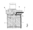
- FIG. 5 shows an alternative.
- the leakage port 8 is opened to the outside.
- a pipe 22 is inserted into the leakage port 8 and closes the channel 21 leading to the low pressure outlet port LPout so that the leakage flow path 7 is diverted out of the machine arrangement 1.
Landscapes
- Engineering & Computer Science (AREA)
- Mechanical Engineering (AREA)
- General Engineering & Computer Science (AREA)
- Chemical & Material Sciences (AREA)
- Combustion & Propulsion (AREA)
- Physics & Mathematics (AREA)
- Fluid Mechanics (AREA)
- Details And Applications Of Rotary Liquid Pumps (AREA)
- Structures Of Non-Positive Displacement Pumps (AREA)
- Details Of Reciprocating Pumps (AREA)
- Examining Or Testing Airtightness (AREA)
Abstract
Description
- The present invention relates to a hydraulic machine arrangement having a housing, a working section and a hollow inside said housing, a supply port arrangement connected to said working area, and a leakage path between said working section and said hollow.
- In the working section of the hydraulic machine arrangement there are, as a rule, parts moving relative to each other. These parts limit at least a pressure chamber the volume of which varies during one working cycle. The pressure in said working section is at least during a part of the working cycle higher than the pressure in the hollow. It is almost impossible to have the contact area between the moving parts absolutely tight so that a certain leakage occurs. Such leakage should be kept at a minimum. However, a certain leakage is acceptable, since this leakage forms a kind of lubrication flow.
- The leakage is collected in the hollow and has to be transported away. To this end, the hollow is connected to a low pressure port of the supply pressure arrangement. When the hydraulic machine arrangement is in form of a pump, the hollow is often connected to a suction port of the supply port arrangement. In this way, it is avoided that a pressure builds up within the hollow.
- The moving parts in the working section show some wear.
- The object underlying the invention is to have the possibility to detect wear with simple means.
- This object is solved with a hydraulic machine arrangement as described at the outset in that said housing is provided with a leakage port connected to said hollow.
- In such a machine arrangement, it is possible to have a look at the leakage flow. The leakage arriving at the hollow can escape through the leakage port. It is therefore possible to obtain information about the amount of the leakage and of the quality of the leakage, if necessary.
- Preferably, said hollow is sealed against said supply port arrangement. In this case, the complete leakage flow has to flow through the leakage port. When the flow through the leakage port is investigated, it can be seen whether the leakage has been increased or not.
- Preferably, said leakage port comprises a connecting geometry accessible from the outside of said housing. This connecting geometry allows for mounting parts and elements at the leakage port, if desired.
- In a preferred embodiment a flow meter is connected to said leakage port. The flow meter is able to detect the flow of leakage through the leakage port. Monitoring of said leakage flow gives information about wear. In most cases leakage increases when wear increases.
- In a preferred embodiment, an outlet of said flow meter is connected to a suction port of said supply port arrangement. This is a simple way to remove the leakage after detecting the leakage flow.
- In another preferred embodiment a closure member is provided closing said leakage port. Not all users of a hydraulic machine arrangement will use the possibility to fix permanently a flow meter to said leakage port. When the flow meter is removed, the closure member can be used to close the leakage port.
- Preferably, said machine arrangement comprises a pressure exchanger and a booster pump. Such a machine arrangement can be used, for example, in a reverse osmosis system of a water purification plant. In such a plant, there are usually a number of such hydraulic machine arrangements arranged in parallel. When the output of such a plant decreases, it is rather simple to identify the machine arrangement causing the problem. As a rule, this is the hydraulic machine arrangement having an abnormal leakage.
- Preferably, a leakage flow path is provided from said booster pump to said pressure exchanger and said leakage port is provided at said pressure exchanger. This means that the leakage of the booster pump and the leakage of the pressure exchanger can be monitored through the same leakage port.
- Preferably said machine arrangement comprises an axial piston pump. Such an axial piston pump can be used as well as booster pump.
- The preferred embodiment of the invention is now described in more detail with reference to the drawing, wherein:
- Fig. 1
- shows a schematic illustration of a hydraulic machine arrangement,
- Fig. 2
- shows an enlarged view of a leakage port,
- Fig. 3
- shows a schematic illustration of a leakage flow path in the hydraulic machine arrangement,
- Fig. 4
- shows schematically a leakage flow diverted to a low pressure outlet port, and
- Fig. 5
- schematically shows a leakage flow path diverted out of the machine arrangement.
-
Figure 1 schematically shows ahydraulic machine arrangement 1 comprising apressure exchanger 2 and abooster pump 3. Thepressure exchanger 2 and thebooster pump 3 are connected by means of a connectingflange 4. Thepressure exchanger 2, thebooster pump 3 and theconnection flange 4 have, for the illustration of the present invention, acommon housing 5. - The
pressure exchanger 2 has a number of rotatingcylinders Fig. 3 ), which are driven by means of anaxis 6. Thepressure exchanger 2 has a high pressure inlet port HPin and a low pressure outlet port LPout. The booster pump has a low pressure inlet port LPin and furthermore thebooster pump 3 has a high pressure outlet port which is not shown in the drawing. The high pressure inlet port HPin, the low pressure outlet port LPout, the low pressure inlet port LPin and the high pressure outlet port (not shown) together form a supply port arrangement. - In the present case, the
booster pump 3 is in form of a vane type pump in which the number of vanes limit a number of pressure chambers together with a rotor in which the vanes are arranged and a stator which is part of thehousing 5. The rotor is arranged eccentrically within in a stator bore so that during rotation the vanes slide radially inwardly and outwardly so that the pressure chambers increase and decrease their volume. - The basic construction of the
pressure exchanger 2 and of thebooster pump 3 is known from the state of the art and will therefore not be described in more detail. - The above described rotating cylinders and the rotor with the vanes form a working section. When the parts of the working section are moved relative to each other a leakage occurs which is acceptable since the leakage forms a lubrication flow. This lubrication flow escapes from the working section into a hollow within the
housing 5. Aleakage flow path 7 is indicated by arrows. It can be seen that theleakage flow path 7 runs from thebooster pump 3 to thepressure exchanger 2. - The
pressure exchanger 2 comprises additionally aleakage port 8 which is connected to theleakage flow path 7, i.e. to the hollow of thehousing 5. Aflow meter 9 is connected to theleakage port 8. Furthermore, the hollow of thehousing 5 is sealed against the supply port arrangement HPin, LPout, LPin so that the complete leakage flow has to run through theleakage port 8 and through theflow meter 9. In this way, it is possible to monitor the leakage flow and to detect whether the leakage flow is constant or whether it increases or decreases. As long as the leakage flow is constant, there is usually no problem. As soon as the leakage flow increases or decreases, this may be an indication of an abnormal wear which requires an inspection of thehydraulic machine arrangement 1. - The flow meter comprises an
outlet 10 which is connected to the low pressure outlet port LPout of thepressure exchanger 2 so that it is possible to dispose of the leakage flow through the low pressure outlet port LPout. - Another possibility is shown with a dotted line. The
outlet 10 of theflow meter 9 is connected to the low pressure inlet port LPin of thebooster pump 3. In this way, the leakage flow is not only disposed of but it is reused in thebooster pump 3. - In some cases it is not required or intended to use permanently the
flow meter 9. - As shown in
figure 2 , theleakage port 8 comprises aconnection geometry 11, e.g. in form a thread. A complementary connection geometry of theflow meter 9 can be screwed into theconnection geometry 11. - If the
flow meter 9 is not used, the user can screw aclosure member 12 into saidleakage port 8 to close theleakage port 8. In this case an alternativeleakage flow path 13 is established connecting the hollow 14 of thehousing 5 with the low pressure outlet port LPout. This connection can be made, if required, by theclosure member 12.
Figures 3 to 5 schematically show more clearly theleakage flow path 7. Reference numerals used infigures 1 and 2 are used infigures 3 to 5 for the same elements. - The
leakage flow path 7 starts at both ends of the vanes of thebooster pump 3. The part of theleakage flow path 7 starting from the axial inner end of thebooster pump 3, i.e. the end neighboring the connectingflange 4, enters directly the connectingflange 4. The part of theleakage flow path 7 starting from the axial outer end of thebooster pump 3 crosses thebooster pump 3 lengthwise and joins with the other part of the leakage flow path in the connectingflange 4. - After passing the connecting
flange 4, theleakage flow path 7 runs through thepressure exchanger 3 outside thecylinders end plate 20. Theend plate 20 comprises theleakage port 8. - As shown in
figure 4 , theleakage port 8 is closed by theclosure member 12, which is in form of a plug or the like. In this case theleakage flow path 7 is diverted to the low pressure output port LPout via achannel 21. -
Figure 5 shows an alternative. In this case theleakage port 8 is opened to the outside. Apipe 22 is inserted into theleakage port 8 and closes thechannel 21 leading to the low pressure outlet port LPout so that theleakage flow path 7 is diverted out of themachine arrangement 1.
Claims (10)
- Hydraulic machine arrangement (1) having a housing (5), a working section and a hollow (14) inside said housing (5), a supply port arrangement LPin, HPin, LPout connected to said working area, and a leakage path (7) between said working section and said hollow (14), characterized in that said housing (5) is provided with a leakage port (8) connected to said hollow (14).
- Hydraulic machine arrangement according to claim 1, characterized in that said hollow (14) is sealed against said supply port arrangement (LPin, HPin, LPout).
- Hydraulic machine arrangement according to claim 1 or 2, characterized in that said leakage port (8) comprises a connecting geometry (11) accessible from the outside of said housing.
- Hydraulic machine arrangement according to claim 3, characterized in that a flow meter (9) is connected to said leakage port (8).
- Hydraulic machine arrangement according to claim 4, characterized in that an outlet (10) of said flow meter (9) is connected to said supply port arrangement (LPin, HPin, LPout).
- Hydraulic machine arrangement according to claim 5, characterized in that said outlet (10) of said flow meter (9) is connected to a suction port LPin of said supply port arrangement (LPin, HPin, LPout).
- Hydraulic machine arrangement according to claim 3, characterized in that a closure member (12) is provided closing said leakage port (8).
- Hydraulic machine arrangement according to any of claims 1 to 7, characterized in that said machine arrangement (1) comprises a pressure exchanger (2) and a booster pump (3).
- Hydraulic machine arrangement according to claim 8, characterized in that said leakage path (7) is provided from said booster pump (3) to said pressure exchanger (2) and said leakage port (8) is provided at said pressure exchanger (2).
- Hydraulic machine arrangement according to any of claims 1 to 9, characterized in that said machine arrangement (1) comprises an axial piston pump.
Priority Applications (4)
| Application Number | Priority Date | Filing Date | Title |
|---|---|---|---|
| ES15174079T ES2731358T3 (en) | 2015-06-26 | 2015-06-26 | Hydraulic machine layout |
| EP15174079.2A EP3109470B1 (en) | 2015-06-26 | 2015-06-26 | Hydraulic machine arrangement |
| CN201610444675.4A CN106286288B (en) | 2015-06-26 | 2016-06-20 | Hydro-mechanical unit |
| US15/187,940 US10288051B2 (en) | 2015-06-26 | 2016-06-21 | Hydraulic machine arrangement |
Applications Claiming Priority (1)
| Application Number | Priority Date | Filing Date | Title |
|---|---|---|---|
| EP15174079.2A EP3109470B1 (en) | 2015-06-26 | 2015-06-26 | Hydraulic machine arrangement |
Publications (2)
| Publication Number | Publication Date |
|---|---|
| EP3109470A1 true EP3109470A1 (en) | 2016-12-28 |
| EP3109470B1 EP3109470B1 (en) | 2019-03-27 |
Family
ID=53491366
Family Applications (1)
| Application Number | Title | Priority Date | Filing Date |
|---|---|---|---|
| EP15174079.2A Active EP3109470B1 (en) | 2015-06-26 | 2015-06-26 | Hydraulic machine arrangement |
Country Status (4)
| Country | Link |
|---|---|
| US (1) | US10288051B2 (en) |
| EP (1) | EP3109470B1 (en) |
| CN (1) | CN106286288B (en) |
| ES (1) | ES2731358T3 (en) |
Cited By (1)
| Publication number | Priority date | Publication date | Assignee | Title |
|---|---|---|---|---|
| ES2795575A1 (en) * | 2019-05-21 | 2020-11-23 | Danfoss As | Device for supplying ports to a machine section of a hydraulic machine arrangement (Machine-translation by Google Translate, not legally binding) |
Families Citing this family (3)
| Publication number | Priority date | Publication date | Assignee | Title |
|---|---|---|---|---|
| CN109964108A (en) * | 2016-08-15 | 2019-07-02 | 海别得公司 | Detecting fluid leaks in pressurized systems of waterjet cutting systems |
| DE102019112792A1 (en) * | 2019-05-15 | 2020-11-19 | Leistritz Pumpen Gmbh | Method for determining a flow volume of a fluid conveyed by a pump |
| ES2848924B2 (en) | 2021-06-04 | 2022-03-29 | Latorre Carrion Manuel | ONE-WAY PRESSURE EXCHANGE DEVICE FOR REVERSE OSMOSIS DESALINATION PLANTS |
Citations (7)
| Publication number | Priority date | Publication date | Assignee | Title |
|---|---|---|---|---|
| GB1378627A (en) * | 1972-04-07 | 1974-12-27 | Grove M H | Apparatus and method incorporating leak detection |
| JPS62178781A (en) * | 1986-01-30 | 1987-08-05 | Tokushu Piston Seisakusho:Kk | Plunger pump packing inspection device |
| DE102005056909A1 (en) * | 2005-11-29 | 2007-05-31 | Bosch Rexroth Ag | Hydraulic gearwheel machine e.g. reversible outer gear wheel motor, for mobile hydraulic system, has covers with front recesses, where one recess is coupled with leakage oil channel of support latches via grooves for forming oil flow path |
| JP2010190383A (en) * | 2009-02-20 | 2010-09-02 | Mitsubishi Heavy Ind Ltd | Sealing device for hydraulic cylinder, hydraulic cylinder device, and operation method for the same |
| US8387558B2 (en) * | 2007-05-23 | 2013-03-05 | Dürr Systems GmbH | Piston rod seal for an insulating cylinder of a coating plant |
| EP2662565A1 (en) * | 2012-05-10 | 2013-11-13 | L'air Liquide, Societe Anonyme Pour L'etude Et L'exploitation Des Procedes Georges Claude | Compression device for cryogenic jet fluid installations |
| WO2014003626A1 (en) * | 2012-06-28 | 2014-01-03 | Atlas Copco Rock Drills Ab | Device and method in respect of a rock drilling machine and rock drilling machine |
Family Cites Families (31)
| Publication number | Priority date | Publication date | Assignee | Title |
|---|---|---|---|---|
| FR1024412A (en) * | 1949-09-20 | 1953-04-01 | Power Jets Res & Dev Ltd | Improvements to sealing devices |
| DE1401400A1 (en) | 1959-09-11 | 1968-12-19 | Karl Eickmann | High pressure rotary piston machine |
| US3507584A (en) * | 1968-03-27 | 1970-04-21 | Us Navy | Axial piston pump for nonlubricating fluids |
| US3582241A (en) | 1969-03-18 | 1971-06-01 | Sperry Rand Corp | Power transmission |
| DE2325242B1 (en) | 1973-05-18 | 1974-10-03 | Wepuko-Hydraulik Gmbh, 7418 Metzingen | Device for supplying the hydrostatic bearing of a piston of a hydrostatic piston pump |
| US3947046A (en) | 1973-05-30 | 1976-03-30 | Riken Piston Ring Kogyo Kabushiki Kaisha | Oil seal ring for internal combustion engine |
| DE2841008A1 (en) | 1978-09-21 | 1980-04-03 | Bosch Gmbh Robert | SLIDING SHOE FOR HYDROSTATIC PISTON MACHINES |
| JPH0756345B2 (en) | 1990-07-09 | 1995-06-14 | 株式会社荏原製作所 | Non-contact end face seal |
| DE4306221A1 (en) | 1993-02-27 | 1994-09-01 | Teves Gmbh Alfred | pump |
| US5571268A (en) | 1993-12-16 | 1996-11-05 | A.W. Chesterton Company | Universal split mechanical seal |
| US5536153A (en) | 1994-06-28 | 1996-07-16 | Edwards; Thomas C. | Non-contact vane-type fluid displacement machine with lubricant separator and sump arrangement |
| US5833438A (en) | 1995-07-31 | 1998-11-10 | Coltec Industries Inc | Variable displacement vane pump having cam seal with seal land |
| JPH1193856A (en) | 1997-09-18 | 1999-04-06 | Jidosha Kiki Co Ltd | Variable displacement pump |
| US6142478A (en) | 1998-02-06 | 2000-11-07 | John Crane Inc. | Gas lubricated slow speed seal |
| US6592126B2 (en) | 2001-07-20 | 2003-07-15 | Flowserve Management Company | Mechanical seal leak detector |
| CN2729318Y (en) | 2004-08-20 | 2005-09-28 | 沈阳工业学院 | Hole hydraulic motor |
| JP2006097497A (en) | 2004-09-28 | 2006-04-13 | Km Kogyo:Kk | Portable power pump mounting stand |
| JP2011094490A (en) | 2009-10-27 | 2011-05-12 | Hitachi Constr Mach Co Ltd | Axial piston type hydraulic rotary machine |
| JP4890604B2 (en) | 2009-11-25 | 2012-03-07 | 日立オートモティブシステムズ株式会社 | Variable displacement pump |
| GB201013844D0 (en) | 2010-08-19 | 2010-09-29 | Rolls Royce Plc | Intershaft seal |
| GB201016759D0 (en) | 2010-10-06 | 2010-11-17 | Nat Oilwell Varco Lp | Seal leakage detection |
| JP5571005B2 (en) * | 2011-01-12 | 2014-08-13 | 株式会社クボタ | Pressure exchange device and performance adjustment method of pressure exchange device |
| EP2715154B1 (en) * | 2011-05-31 | 2017-10-11 | Volvo Construction Equipment AB | A hydraulic system and a method for controlling a hydraulic system |
| DK2762730T3 (en) * | 2011-09-30 | 2019-09-30 | Kubota Kk | PRESSURE EXCHANGE DEVICES |
| JP5764453B2 (en) | 2011-10-03 | 2015-08-19 | カヤバ工業株式会社 | Vane pump |
| DE102011116858B4 (en) | 2011-10-25 | 2018-10-11 | Danfoss A/S | Vane machine |
| DE102011116869B4 (en) | 2011-10-25 | 2015-07-02 | Danfoss A/S | Vane machine |
| US9945216B2 (en) * | 2013-10-03 | 2018-04-17 | Energy Recovery, Inc. | Frac system with hydraulic energy transfer system |
| CN203532360U (en) * | 2013-11-14 | 2014-04-09 | 中联重科股份有限公司 | hydraulic booster system |
| CN103671302B (en) * | 2013-11-29 | 2016-04-06 | 苏州大学 | Hinge rod hydraulic pressure booster and hydraulic press |
| US9617994B2 (en) | 2014-04-18 | 2017-04-11 | Delaware Capital Formation, Inc. | Pump with mechanical seal assembly |
-
2015
- 2015-06-26 EP EP15174079.2A patent/EP3109470B1/en active Active
- 2015-06-26 ES ES15174079T patent/ES2731358T3/en active Active
-
2016
- 2016-06-20 CN CN201610444675.4A patent/CN106286288B/en active Active
- 2016-06-21 US US15/187,940 patent/US10288051B2/en active Active
Patent Citations (7)
| Publication number | Priority date | Publication date | Assignee | Title |
|---|---|---|---|---|
| GB1378627A (en) * | 1972-04-07 | 1974-12-27 | Grove M H | Apparatus and method incorporating leak detection |
| JPS62178781A (en) * | 1986-01-30 | 1987-08-05 | Tokushu Piston Seisakusho:Kk | Plunger pump packing inspection device |
| DE102005056909A1 (en) * | 2005-11-29 | 2007-05-31 | Bosch Rexroth Ag | Hydraulic gearwheel machine e.g. reversible outer gear wheel motor, for mobile hydraulic system, has covers with front recesses, where one recess is coupled with leakage oil channel of support latches via grooves for forming oil flow path |
| US8387558B2 (en) * | 2007-05-23 | 2013-03-05 | Dürr Systems GmbH | Piston rod seal for an insulating cylinder of a coating plant |
| JP2010190383A (en) * | 2009-02-20 | 2010-09-02 | Mitsubishi Heavy Ind Ltd | Sealing device for hydraulic cylinder, hydraulic cylinder device, and operation method for the same |
| EP2662565A1 (en) * | 2012-05-10 | 2013-11-13 | L'air Liquide, Societe Anonyme Pour L'etude Et L'exploitation Des Procedes Georges Claude | Compression device for cryogenic jet fluid installations |
| WO2014003626A1 (en) * | 2012-06-28 | 2014-01-03 | Atlas Copco Rock Drills Ab | Device and method in respect of a rock drilling machine and rock drilling machine |
Cited By (4)
| Publication number | Priority date | Publication date | Assignee | Title |
|---|---|---|---|---|
| ES2795575A1 (en) * | 2019-05-21 | 2020-11-23 | Danfoss As | Device for supplying ports to a machine section of a hydraulic machine arrangement (Machine-translation by Google Translate, not legally binding) |
| DE102019113536A1 (en) * | 2019-05-21 | 2020-11-26 | Danfoss A/S | Device for providing connections to a machine area of a hydraulic machine arrangement |
| US11067100B2 (en) | 2019-05-21 | 2021-07-20 | Danfoss A/S | Device for supplying ports to a machine section of a hydraulic machine arrangement |
| DE102019113536B4 (en) | 2019-05-21 | 2022-04-21 | Danfoss A/S | Device for providing connections to a machine section of a hydraulic machine arrangement |
Also Published As
| Publication number | Publication date |
|---|---|
| EP3109470B1 (en) | 2019-03-27 |
| US10288051B2 (en) | 2019-05-14 |
| US20160377070A1 (en) | 2016-12-29 |
| ES2731358T3 (en) | 2019-11-15 |
| CN106286288A (en) | 2017-01-04 |
| CN106286288B (en) | 2019-03-15 |
Similar Documents
| Publication | Publication Date | Title |
|---|---|---|
| US10288051B2 (en) | Hydraulic machine arrangement | |
| RU2651108C2 (en) | Rotary isobaric pressure exchanger system with lubrication system | |
| US9022760B2 (en) | High pressure seal vent | |
| US20150192130A1 (en) | Centrifugal multiple-impeller electric pump | |
| CN101208518B (en) | screw pump | |
| MY161481A (en) | Method and apparatus for managing fluid flow within a screw pump system | |
| DE502007002365D1 (en) | PUMP | |
| MX2016012742A (en) | Vane oil pump. | |
| JP6567172B2 (en) | A flushable device for measuring fluid flow-through processes. | |
| RU2559411C2 (en) | Screw oil-filled compressor unit (versions), and lubrication system of bearings of screw oil-filled compressor unit | |
| RU2373432C1 (en) | Packaged centrifugal pump | |
| CN218325504U (en) | A centrifugal pump impeller balance hole and rear sealing ring structure | |
| CN105952657A (en) | Oil-submersible pump | |
| WO2020048947A1 (en) | A method for detecting leakage in a positive displacement pump | |
| RU2640878C1 (en) | Hydraulic electric machine body | |
| EP3236080B1 (en) | Rotary machine system | |
| CN104204518B (en) | Improved pumping installations and the control method of described pumping installations | |
| US20180073513A1 (en) | Method for inspecting rotary machine, and rotary machine | |
| RU135738U1 (en) | MULTI-STAGE CENTRIFUGAL PUMP WITH MEETING LOCATION OF WORKING WHEEL GROUPS | |
| RU123076U1 (en) | CENTRIFUGAL MULTI-STAGE ELECTRIC PUMP | |
| PL225445B1 (en) | Whirling high-pressure pump | |
| RU2761502C1 (en) | Turbomachine housing with at least one lid, turbomachine and method for manufacturing lid | |
| RU47060U1 (en) | CENTRIFUGAL MULTI-STAGE PUMP | |
| RU98501U1 (en) | DEVICE FOR DETERMINING THE CENTRIFUGAL PUMP EFFICIENCY | |
| RU30401U1 (en) | CENTRIFUGAL PUMP DRAINAGE DEVICE |
Legal Events
| Date | Code | Title | Description |
|---|---|---|---|
| PUAI | Public reference made under article 153(3) epc to a published international application that has entered the european phase |
Free format text: ORIGINAL CODE: 0009012 |
|
| STAA | Information on the status of an ep patent application or granted ep patent |
Free format text: STATUS: THE APPLICATION HAS BEEN PUBLISHED |
|
| AK | Designated contracting states |
Kind code of ref document: A1 Designated state(s): AL AT BE BG CH CY CZ DE DK EE ES FI FR GB GR HR HU IE IS IT LI LT LU LV MC MK MT NL NO PL PT RO RS SE SI SK SM TR |
|
| AX | Request for extension of the european patent |
Extension state: BA ME |
|
| STAA | Information on the status of an ep patent application or granted ep patent |
Free format text: STATUS: REQUEST FOR EXAMINATION WAS MADE |
|
| 17P | Request for examination filed |
Effective date: 20170607 |
|
| RBV | Designated contracting states (corrected) |
Designated state(s): AL AT BE BG CH CY CZ DE DK EE ES FI FR GB GR HR HU IE IS IT LI LT LU LV MC MK MT NL NO PL PT RO RS SE SI SK SM TR |
|
| STAA | Information on the status of an ep patent application or granted ep patent |
Free format text: STATUS: EXAMINATION IS IN PROGRESS |
|
| 17Q | First examination report despatched |
Effective date: 20180517 |
|
| REG | Reference to a national code |
Ref country code: DE Ref legal event code: R079 Ref document number: 602015027023 Country of ref document: DE Free format text: PREVIOUS MAIN CLASS: F04B0001120000 Ipc: F04B0019220000 |
|
| GRAP | Despatch of communication of intention to grant a patent |
Free format text: ORIGINAL CODE: EPIDOSNIGR1 |
|
| STAA | Information on the status of an ep patent application or granted ep patent |
Free format text: STATUS: GRANT OF PATENT IS INTENDED |
|
| RIC1 | Information provided on ipc code assigned before grant |
Ipc: F04B 49/10 20060101ALI20181108BHEP Ipc: F04B 1/12 20060101ALI20181108BHEP Ipc: F03C 1/06 20060101ALI20181108BHEP Ipc: F04F 13/00 20090101ALI20181108BHEP Ipc: F04B 19/22 20060101AFI20181108BHEP |
|
| INTG | Intention to grant announced |
Effective date: 20181130 |
|
| GRAS | Grant fee paid |
Free format text: ORIGINAL CODE: EPIDOSNIGR3 |
|
| GRAA | (expected) grant |
Free format text: ORIGINAL CODE: 0009210 |
|
| STAA | Information on the status of an ep patent application or granted ep patent |
Free format text: STATUS: THE PATENT HAS BEEN GRANTED |
|
| AK | Designated contracting states |
Kind code of ref document: B1 Designated state(s): AL AT BE BG CH CY CZ DE DK EE ES FI FR GB GR HR HU IE IS IT LI LT LU LV MC MK MT NL NO PL PT RO RS SE SI SK SM TR |
|
| REG | Reference to a national code |
Ref country code: GB Ref legal event code: FG4D |
|
| REG | Reference to a national code |
Ref country code: CH Ref legal event code: EP |
|
| REG | Reference to a national code |
Ref country code: AT Ref legal event code: REF Ref document number: 1113408 Country of ref document: AT Kind code of ref document: T Effective date: 20190415 |
|
| REG | Reference to a national code |
Ref country code: IE Ref legal event code: FG4D |
|
| REG | Reference to a national code |
Ref country code: DE Ref legal event code: R096 Ref document number: 602015027023 Country of ref document: DE |
|
| PG25 | Lapsed in a contracting state [announced via postgrant information from national office to epo] |
Ref country code: SE Free format text: LAPSE BECAUSE OF FAILURE TO SUBMIT A TRANSLATION OF THE DESCRIPTION OR TO PAY THE FEE WITHIN THE PRESCRIBED TIME-LIMIT Effective date: 20190327 Ref country code: LT Free format text: LAPSE BECAUSE OF FAILURE TO SUBMIT A TRANSLATION OF THE DESCRIPTION OR TO PAY THE FEE WITHIN THE PRESCRIBED TIME-LIMIT Effective date: 20190327 Ref country code: NO Free format text: LAPSE BECAUSE OF FAILURE TO SUBMIT A TRANSLATION OF THE DESCRIPTION OR TO PAY THE FEE WITHIN THE PRESCRIBED TIME-LIMIT Effective date: 20190627 Ref country code: FI Free format text: LAPSE BECAUSE OF FAILURE TO SUBMIT A TRANSLATION OF THE DESCRIPTION OR TO PAY THE FEE WITHIN THE PRESCRIBED TIME-LIMIT Effective date: 20190327 |
|
| REG | Reference to a national code |
Ref country code: NL Ref legal event code: MP Effective date: 20190327 |
|
| PG25 | Lapsed in a contracting state [announced via postgrant information from national office to epo] |
Ref country code: BG Free format text: LAPSE BECAUSE OF FAILURE TO SUBMIT A TRANSLATION OF THE DESCRIPTION OR TO PAY THE FEE WITHIN THE PRESCRIBED TIME-LIMIT Effective date: 20190627 Ref country code: RS Free format text: LAPSE BECAUSE OF FAILURE TO SUBMIT A TRANSLATION OF THE DESCRIPTION OR TO PAY THE FEE WITHIN THE PRESCRIBED TIME-LIMIT Effective date: 20190327 Ref country code: NL Free format text: LAPSE BECAUSE OF FAILURE TO SUBMIT A TRANSLATION OF THE DESCRIPTION OR TO PAY THE FEE WITHIN THE PRESCRIBED TIME-LIMIT Effective date: 20190327 Ref country code: LV Free format text: LAPSE BECAUSE OF FAILURE TO SUBMIT A TRANSLATION OF THE DESCRIPTION OR TO PAY THE FEE WITHIN THE PRESCRIBED TIME-LIMIT Effective date: 20190327 Ref country code: HR Free format text: LAPSE BECAUSE OF FAILURE TO SUBMIT A TRANSLATION OF THE DESCRIPTION OR TO PAY THE FEE WITHIN THE PRESCRIBED TIME-LIMIT Effective date: 20190327 Ref country code: GR Free format text: LAPSE BECAUSE OF FAILURE TO SUBMIT A TRANSLATION OF THE DESCRIPTION OR TO PAY THE FEE WITHIN THE PRESCRIBED TIME-LIMIT Effective date: 20190628 |
|
| REG | Reference to a national code |
Ref country code: AT Ref legal event code: MK05 Ref document number: 1113408 Country of ref document: AT Kind code of ref document: T Effective date: 20190327 |
|
| PG25 | Lapsed in a contracting state [announced via postgrant information from national office to epo] |
Ref country code: SK Free format text: LAPSE BECAUSE OF FAILURE TO SUBMIT A TRANSLATION OF THE DESCRIPTION OR TO PAY THE FEE WITHIN THE PRESCRIBED TIME-LIMIT Effective date: 20190327 Ref country code: IT Free format text: LAPSE BECAUSE OF FAILURE TO SUBMIT A TRANSLATION OF THE DESCRIPTION OR TO PAY THE FEE WITHIN THE PRESCRIBED TIME-LIMIT Effective date: 20190327 Ref country code: EE Free format text: LAPSE BECAUSE OF FAILURE TO SUBMIT A TRANSLATION OF THE DESCRIPTION OR TO PAY THE FEE WITHIN THE PRESCRIBED TIME-LIMIT Effective date: 20190327 Ref country code: AL Free format text: LAPSE BECAUSE OF FAILURE TO SUBMIT A TRANSLATION OF THE DESCRIPTION OR TO PAY THE FEE WITHIN THE PRESCRIBED TIME-LIMIT Effective date: 20190327 Ref country code: PT Free format text: LAPSE BECAUSE OF FAILURE TO SUBMIT A TRANSLATION OF THE DESCRIPTION OR TO PAY THE FEE WITHIN THE PRESCRIBED TIME-LIMIT Effective date: 20190727 Ref country code: RO Free format text: LAPSE BECAUSE OF FAILURE TO SUBMIT A TRANSLATION OF THE DESCRIPTION OR TO PAY THE FEE WITHIN THE PRESCRIBED TIME-LIMIT Effective date: 20190327 Ref country code: CZ Free format text: LAPSE BECAUSE OF FAILURE TO SUBMIT A TRANSLATION OF THE DESCRIPTION OR TO PAY THE FEE WITHIN THE PRESCRIBED TIME-LIMIT Effective date: 20190327 |
|
| PG25 | Lapsed in a contracting state [announced via postgrant information from national office to epo] |
Ref country code: PL Free format text: LAPSE BECAUSE OF FAILURE TO SUBMIT A TRANSLATION OF THE DESCRIPTION OR TO PAY THE FEE WITHIN THE PRESCRIBED TIME-LIMIT Effective date: 20190327 Ref country code: SM Free format text: LAPSE BECAUSE OF FAILURE TO SUBMIT A TRANSLATION OF THE DESCRIPTION OR TO PAY THE FEE WITHIN THE PRESCRIBED TIME-LIMIT Effective date: 20190327 |
|
| PG25 | Lapsed in a contracting state [announced via postgrant information from national office to epo] |
Ref country code: AT Free format text: LAPSE BECAUSE OF FAILURE TO SUBMIT A TRANSLATION OF THE DESCRIPTION OR TO PAY THE FEE WITHIN THE PRESCRIBED TIME-LIMIT Effective date: 20190327 Ref country code: IS Free format text: LAPSE BECAUSE OF FAILURE TO SUBMIT A TRANSLATION OF THE DESCRIPTION OR TO PAY THE FEE WITHIN THE PRESCRIBED TIME-LIMIT Effective date: 20190727 |
|
| REG | Reference to a national code |
Ref country code: DE Ref legal event code: R097 Ref document number: 602015027023 Country of ref document: DE |
|
| PG25 | Lapsed in a contracting state [announced via postgrant information from national office to epo] |
Ref country code: DK Free format text: LAPSE BECAUSE OF FAILURE TO SUBMIT A TRANSLATION OF THE DESCRIPTION OR TO PAY THE FEE WITHIN THE PRESCRIBED TIME-LIMIT Effective date: 20190327 Ref country code: MC Free format text: LAPSE BECAUSE OF FAILURE TO SUBMIT A TRANSLATION OF THE DESCRIPTION OR TO PAY THE FEE WITHIN THE PRESCRIBED TIME-LIMIT Effective date: 20190327 |
|
| REG | Reference to a national code |
Ref country code: CH Ref legal event code: PL |
|
| PLBE | No opposition filed within time limit |
Free format text: ORIGINAL CODE: 0009261 |
|
| STAA | Information on the status of an ep patent application or granted ep patent |
Free format text: STATUS: NO OPPOSITION FILED WITHIN TIME LIMIT |
|
| PG25 | Lapsed in a contracting state [announced via postgrant information from national office to epo] |
Ref country code: SI Free format text: LAPSE BECAUSE OF FAILURE TO SUBMIT A TRANSLATION OF THE DESCRIPTION OR TO PAY THE FEE WITHIN THE PRESCRIBED TIME-LIMIT Effective date: 20190327 |
|
| 26N | No opposition filed |
Effective date: 20200103 |
|
| REG | Reference to a national code |
Ref country code: BE Ref legal event code: MM Effective date: 20190630 |
|
| PG25 | Lapsed in a contracting state [announced via postgrant information from national office to epo] |
Ref country code: TR Free format text: LAPSE BECAUSE OF FAILURE TO SUBMIT A TRANSLATION OF THE DESCRIPTION OR TO PAY THE FEE WITHIN THE PRESCRIBED TIME-LIMIT Effective date: 20190327 |
|
| PG25 | Lapsed in a contracting state [announced via postgrant information from national office to epo] |
Ref country code: IE Free format text: LAPSE BECAUSE OF NON-PAYMENT OF DUE FEES Effective date: 20190626 |
|
| PG25 | Lapsed in a contracting state [announced via postgrant information from national office to epo] |
Ref country code: LU Free format text: LAPSE BECAUSE OF NON-PAYMENT OF DUE FEES Effective date: 20190626 Ref country code: BE Free format text: LAPSE BECAUSE OF NON-PAYMENT OF DUE FEES Effective date: 20190630 Ref country code: LI Free format text: LAPSE BECAUSE OF NON-PAYMENT OF DUE FEES Effective date: 20190630 Ref country code: CH Free format text: LAPSE BECAUSE OF NON-PAYMENT OF DUE FEES Effective date: 20190630 |
|
| PG25 | Lapsed in a contracting state [announced via postgrant information from national office to epo] |
Ref country code: FR Free format text: LAPSE BECAUSE OF NON-PAYMENT OF DUE FEES Effective date: 20190630 |
|
| PG25 | Lapsed in a contracting state [announced via postgrant information from national office to epo] |
Ref country code: CY Free format text: LAPSE BECAUSE OF FAILURE TO SUBMIT A TRANSLATION OF THE DESCRIPTION OR TO PAY THE FEE WITHIN THE PRESCRIBED TIME-LIMIT Effective date: 20190327 |
|
| PG25 | Lapsed in a contracting state [announced via postgrant information from national office to epo] |
Ref country code: HU Free format text: LAPSE BECAUSE OF FAILURE TO SUBMIT A TRANSLATION OF THE DESCRIPTION OR TO PAY THE FEE WITHIN THE PRESCRIBED TIME-LIMIT; INVALID AB INITIO Effective date: 20150626 Ref country code: MT Free format text: LAPSE BECAUSE OF FAILURE TO SUBMIT A TRANSLATION OF THE DESCRIPTION OR TO PAY THE FEE WITHIN THE PRESCRIBED TIME-LIMIT Effective date: 20190327 |
|
| PG25 | Lapsed in a contracting state [announced via postgrant information from national office to epo] |
Ref country code: MK Free format text: LAPSE BECAUSE OF FAILURE TO SUBMIT A TRANSLATION OF THE DESCRIPTION OR TO PAY THE FEE WITHIN THE PRESCRIBED TIME-LIMIT Effective date: 20190327 |
|
| P01 | Opt-out of the competence of the unified patent court (upc) registered |
Effective date: 20230621 |
|
| PGFP | Annual fee paid to national office [announced via postgrant information from national office to epo] |
Ref country code: ES Payment date: 20250707 Year of fee payment: 11 |
|
| PGFP | Annual fee paid to national office [announced via postgrant information from national office to epo] |
Ref country code: GB Payment date: 20260511 Year of fee payment: 12 |
|
| PGFP | Annual fee paid to national office [announced via postgrant information from national office to epo] |
Ref country code: DE Payment date: 20260506 Year of fee payment: 12 |