EP3109085A1 - Work vehicle - Google Patents
Work vehicle Download PDFInfo
- Publication number
- EP3109085A1 EP3109085A1 EP16170022.4A EP16170022A EP3109085A1 EP 3109085 A1 EP3109085 A1 EP 3109085A1 EP 16170022 A EP16170022 A EP 16170022A EP 3109085 A1 EP3109085 A1 EP 3109085A1
- Authority
- EP
- European Patent Office
- Prior art keywords
- work vehicle
- engine
- radiator
- bonnet
- particulate filter
- Prior art date
- Legal status (The legal status is an assumption and is not a legal conclusion. Google has not performed a legal analysis and makes no representation as to the accuracy of the status listed.)
- Granted
Links
Images



Classifications
-
- B—PERFORMING OPERATIONS; TRANSPORTING
- B60—VEHICLES IN GENERAL
- B60K—ARRANGEMENT OR MOUNTING OF PROPULSION UNITS OR OF TRANSMISSIONS IN VEHICLES; ARRANGEMENT OR MOUNTING OF PLURAL DIVERSE PRIME-MOVERS IN VEHICLES; AUXILIARY DRIVES FOR VEHICLES; INSTRUMENTATION OR DASHBOARDS FOR VEHICLES; ARRANGEMENTS IN CONNECTION WITH COOLING, AIR INTAKE, GAS EXHAUST OR FUEL SUPPLY OF PROPULSION UNITS IN VEHICLES
- B60K13/00—Arrangement in connection with combustion air intake or gas exhaust of propulsion units
- B60K13/04—Arrangement in connection with combustion air intake or gas exhaust of propulsion units concerning exhaust
-
- F—MECHANICAL ENGINEERING; LIGHTING; HEATING; WEAPONS; BLASTING
- F01—MACHINES OR ENGINES IN GENERAL; ENGINE PLANTS IN GENERAL; STEAM ENGINES
- F01N—GAS-FLOW SILENCERS OR EXHAUST APPARATUS FOR MACHINES OR ENGINES IN GENERAL; GAS-FLOW SILENCERS OR EXHAUST APPARATUS FOR INTERNAL-COMBUSTION ENGINES
- F01N13/00—Exhaust or silencing apparatus characterised by constructional features
- F01N13/009—Exhaust or silencing apparatus characterised by constructional features having two or more separate purifying devices arranged in series
-
- F—MECHANICAL ENGINEERING; LIGHTING; HEATING; WEAPONS; BLASTING
- F01—MACHINES OR ENGINES IN GENERAL; ENGINE PLANTS IN GENERAL; STEAM ENGINES
- F01N—GAS-FLOW SILENCERS OR EXHAUST APPARATUS FOR MACHINES OR ENGINES IN GENERAL; GAS-FLOW SILENCERS OR EXHAUST APPARATUS FOR INTERNAL-COMBUSTION ENGINES
- F01N13/00—Exhaust or silencing apparatus characterised by constructional features
- F01N13/18—Construction facilitating manufacture, assembly, or disassembly
- F01N13/1805—Fixing exhaust manifolds, exhaust pipes or pipe sections to each other, to engine or to vehicle body
-
- F—MECHANICAL ENGINEERING; LIGHTING; HEATING; WEAPONS; BLASTING
- F01—MACHINES OR ENGINES IN GENERAL; ENGINE PLANTS IN GENERAL; STEAM ENGINES
- F01N—GAS-FLOW SILENCERS OR EXHAUST APPARATUS FOR MACHINES OR ENGINES IN GENERAL; GAS-FLOW SILENCERS OR EXHAUST APPARATUS FOR INTERNAL-COMBUSTION ENGINES
- F01N3/00—Exhaust or silencing apparatus having means for purifying, rendering innocuous, or otherwise treating exhaust
- F01N3/02—Exhaust or silencing apparatus having means for purifying, rendering innocuous, or otherwise treating exhaust for cooling, or for removing solid constituents of, exhaust
- F01N3/021—Exhaust or silencing apparatus having means for purifying, rendering innocuous, or otherwise treating exhaust for cooling, or for removing solid constituents of, exhaust by means of filters
-
- F—MECHANICAL ENGINEERING; LIGHTING; HEATING; WEAPONS; BLASTING
- F01—MACHINES OR ENGINES IN GENERAL; ENGINE PLANTS IN GENERAL; STEAM ENGINES
- F01N—GAS-FLOW SILENCERS OR EXHAUST APPARATUS FOR MACHINES OR ENGINES IN GENERAL; GAS-FLOW SILENCERS OR EXHAUST APPARATUS FOR INTERNAL-COMBUSTION ENGINES
- F01N3/00—Exhaust or silencing apparatus having means for purifying, rendering innocuous, or otherwise treating exhaust
- F01N3/08—Exhaust or silencing apparatus having means for purifying, rendering innocuous, or otherwise treating exhaust for rendering innocuous
- F01N3/10—Exhaust or silencing apparatus having means for purifying, rendering innocuous, or otherwise treating exhaust for rendering innocuous by thermal or catalytic conversion of noxious components of exhaust
- F01N3/18—Exhaust or silencing apparatus having means for purifying, rendering innocuous, or otherwise treating exhaust for rendering innocuous by thermal or catalytic conversion of noxious components of exhaust characterised by methods of operation; Control
- F01N3/20—Exhaust or silencing apparatus having means for purifying, rendering innocuous, or otherwise treating exhaust for rendering innocuous by thermal or catalytic conversion of noxious components of exhaust characterised by methods of operation; Control specially adapted for catalytic conversion
- F01N3/206—Adding periodically or continuously substances to exhaust gases for promoting purification, e.g. catalytic material in liquid form, NOx reducing agents
- F01N3/2066—Selective catalytic reduction [SCR]
-
- B—PERFORMING OPERATIONS; TRANSPORTING
- B60—VEHICLES IN GENERAL
- B60Y—INDEXING SCHEME RELATING TO ASPECTS CROSS-CUTTING VEHICLE TECHNOLOGY
- B60Y2200/00—Type of vehicle
- B60Y2200/20—Off-Road Vehicles
- B60Y2200/22—Agricultural vehicles
- B60Y2200/221—Tractors
-
- F—MECHANICAL ENGINEERING; LIGHTING; HEATING; WEAPONS; BLASTING
- F01—MACHINES OR ENGINES IN GENERAL; ENGINE PLANTS IN GENERAL; STEAM ENGINES
- F01N—GAS-FLOW SILENCERS OR EXHAUST APPARATUS FOR MACHINES OR ENGINES IN GENERAL; GAS-FLOW SILENCERS OR EXHAUST APPARATUS FOR INTERNAL-COMBUSTION ENGINES
- F01N2590/00—Exhaust or silencing apparatus adapted to particular use, e.g. for military applications, airplanes, submarines
- F01N2590/08—Exhaust or silencing apparatus adapted to particular use, e.g. for military applications, airplanes, submarines for heavy duty applications, e.g. trucks, buses, tractors, locomotives
-
- Y—GENERAL TAGGING OF NEW TECHNOLOGICAL DEVELOPMENTS; GENERAL TAGGING OF CROSS-SECTIONAL TECHNOLOGIES SPANNING OVER SEVERAL SECTIONS OF THE IPC; TECHNICAL SUBJECTS COVERED BY FORMER USPC CROSS-REFERENCE ART COLLECTIONS [XRACs] AND DIGESTS
- Y02—TECHNOLOGIES OR APPLICATIONS FOR MITIGATION OR ADAPTATION AGAINST CLIMATE CHANGE
- Y02A—TECHNOLOGIES FOR ADAPTATION TO CLIMATE CHANGE
- Y02A50/00—TECHNOLOGIES FOR ADAPTATION TO CLIMATE CHANGE in human health protection, e.g. against extreme weather
- Y02A50/20—Air quality improvement or preservation, e.g. vehicle emission control or emission reduction by using catalytic converters
-
- Y—GENERAL TAGGING OF NEW TECHNOLOGICAL DEVELOPMENTS; GENERAL TAGGING OF CROSS-SECTIONAL TECHNOLOGIES SPANNING OVER SEVERAL SECTIONS OF THE IPC; TECHNICAL SUBJECTS COVERED BY FORMER USPC CROSS-REFERENCE ART COLLECTIONS [XRACs] AND DIGESTS
- Y02—TECHNOLOGIES OR APPLICATIONS FOR MITIGATION OR ADAPTATION AGAINST CLIMATE CHANGE
- Y02T—CLIMATE CHANGE MITIGATION TECHNOLOGIES RELATED TO TRANSPORTATION
- Y02T10/00—Road transport of goods or passengers
- Y02T10/10—Internal combustion engine [ICE] based vehicles
- Y02T10/12—Improving ICE efficiencies
Definitions
- the present invention relates to the technology of a work vehicle, and more specifically to the technology of a work vehicle provided with a diesel particulate filter (DPF) and a selective catalytic reduction device (SCR) that purify an exhaust gas of an engine.
- DPF diesel particulate filter
- SCR selective catalytic reduction device
- JP 2014-105549 A describes an engine device that includes a first case (DPF) and a second case (SCR).
- the first case (DPF) removes particulate matter (PM) contained in the exhaust gas.
- the second case (SCR) removes nitrogen oxides contained in the exhaust gas.
- the first case and the second case are disposed on a top side of the engine.
- the technical problem is to provide a work vehicle with a low bonnet.
- a work vehicle comprising: a driver's seat; a bonnet disposed forward of the seat; and an engine arranged under the bonnet; characterised in that a diesel particulate filter and an selective catalytic reduction configured to purify an exhaust gas of the engine, the diesel particulate filter and the selective catalytic reduction being arranged under the bonnet and forward of the engine.
- the diesel particulate filter (hereinafter DPF) and the selective catalytic reduction (hereinafter SCR) are disposed not over the engine but forward of the engine. Thereby the height of the bonnet can be decreased.
- the DPF, the SCR and the engine are disposed not next to the engine with respect to the width direction of the work vehicle. Thereby an increase in a width dimension of the work vehicle can be avoided.
- the width direction is a right-left direction with respect to the travelling direction of the work vehicle.
- the diesel particulate filter and the selective catalytic reduction are disposed side by side along the width direction of the work vehicle.
- the length of the bonnet can be decreased.
- At least one of the diesel particulate filter and the selective catalytic reduction has a shape elongated along one dimension; and the diesel particulate filter and/or the selective catalytic reduction are disposed such that the longitudinal dimension of at least one of the diesel particulate filter and the selective catalytic reduction is oriented along an up-down direction of the work vehicle.
- the work vehicle further comprises: a radiator configured to cool a coolant of the engine, the radiator being disposed under the bonnet and forward of the diesel particulate filter and the selective catalytic reduction.
- the ambient air flows into the space under the bonnet and passes through the radiator, and then reaches to the DPF and the SCR. This enables the radiator to receive the ambient air which is not influenced by the heat from the DPF and SCR. Thereby the ambient air can effectively cool down the coolant in the radiator.
- the radiator mentioned above is inclined along a front-back direction of the work vehicle.
- the inclined radiator needs less height in the space under the bonnet, comparing to its actual height dimension. Thereby, the height of the space formed under the bonnet can be reduced.
- the radiator has a principal surface for exchanging heat between the ambient air and a coolant of the engine.
- the principal surface is preferably directed toward the forward direction of the work vehicle.
- any radiator mentioned above is inclined along the front-back direction such that the upper end of the radiator is positioned at the back of the lower end of the radiator in a plane view.
- the radiator is accommodated in the space formed between the front wheel and the bonnet such that the inclined principal surface of the radiator is arranged roughly along the front wheel.
- the space can effectively accommodate the radiator, which leads to downsizing of the space under the bonnet.
- Another preferable work vehicle with any one of the radiators mentioned above further comprises an air cleaner configured to purify the ambient air to be supplied to the engine, the air cleaner being disposed under the bonnet such that at least a portion thereof overlaps with the radiator in a plan view and a front view.
- the inclined radiator forms a space between its principal surface and the bonnet, and another space under its principal surface.
- the air cleaner is then disposed in either one of these spaces. Thereby the air cleaner can be accommodated in the space under the bonnet without extending the space for the air cleaner.
- radiator fan configured to be driven by the engine and cool the radiator, the radiator fan being disposed between the radiator and both the diesel particulate filter and the selective catalytic reduction.
- the radiator fan shields the heat irradiated from the engine placed at the back of the DPF and SCR. Therefore, the efficiency of the radiator can be maintained or be improved.
- the radiator fan is located closer to the radiator than to the DPF and the SCR. Thereby, the wind from the radiator fan can hit the radiator and can effectively cool it down.
- the work vehicle with the radiator fan further comprises a shaft connecting the engine and the radiator fan and linearly extending between the diesel particulate filter and the selective catalytic reduction, and configured to transmit a drive force of the engine to the radiator fan.
- the engine and radiator fan are connected by the shaft which linearly extends between the DPF and the SCR without skirting around the DPF and the SCR.
- the radiator fan can be driven by a simple structure.
- a work vehicle further comprises a shielding means disposed under the bonnet and configured to at least partially shield wind towards at least one of the diesel particulate filter and the selective catalytic reduction.
- the shielding means blocks at least partially the wind which blows toward the DPF and SCR. Thereby the temperature of the DPF and the SCR can be maintained without being cooled down.
- the shielding means mentioned above is configured to surround at least the front side of at least one of the diesel particulate filter and the selective catalytic reduction.
- the DPF and SCR can be effectively protected from the wind which blows from forward of the work vehicle.
- the "front side” is with respect to the travelling direction of the work vehicle.
- the diesel particulate filter and the selective catalytic reduction are arranged to form a passage of wind such that the passage linearly extends toward the engine.
- the DPF and the SCR preferably form the passage of wind such that the passage linearly extends toward the engine.
- the wind can directly reach to the engine through the passage. Thereby the engine can be effectively cooled down.
- the DPF and the SCR are spaced away from each other to form the passage between them.
- each of the diesel particulate filter and the selective catalytic reduction is arranged either on the right side or the left side with respect to a virtual line extending along the front-back direction of the work vehicle, the virtual line further extending through the centre of the engine with respect to width direction of the work vehicle.
- the DPF and the SCR form a passage of wind from the radiator fan to the engine such that the passage extends linearly from the radiator fan towards the centre portion of the engine with respect to the width direction of the work vehicle in the front view.
- the wind from the radiator fan can directly reach to the centre portion of the engine and effectively cool down the engine.
- the DPF and the SCR form such a passage therebetween.
- any one of the work vehicles mentioned above further comprises first and second shielding members disposed under the bonnet; the first shielding member surrounding at least the front side of the diesel particulate filter, and the second shielding member surrounding at least the front side of the selective catalytic reduction.
- the first shielding member and the second shielding member form a passage of wind such that the passage linearly extends toward the engine and between the first and second shielding members.
- the first and second shielding members preferably form the passage of the wind such that the passage linearly guides the wind to the engine.
- each of the first and second shielding members has a wind blocking part and a wind guiding part.
- the wind blocking part is located forward of the DPF or SCR.
- the wind guiding parts of the first and second shielding members are arranged to form the passage therebetween.
- any structure and/or function of one embodiment can be adopted in another embodiment as long as the new combination is compatible.
- the "up,” “down,” 'front,” “forward,” “back,” “backward,” “left,” and “right” directions are directions with respect to the travelling direction of a work vehicle. These directions are denoted by the arrow U for “up”, the arrow D for “down”, the arrow F for "front” and “forward”, the arrow B for “back” and “backward”, the arrow L for "left”, and the arrow R for “right” in the drawings.
- FIG. 1 a general configuration of a tractor 1, which is an example of a work vehicle according to the present invention, will be described.
- the tractor 1 mainly includes a vehicle body frame 2, front wheels 3, 3, rear wheels 4, 4, an engine 5, a bonnet 6, a transmission 7, a steering wheel 8, and a seat 9.
- the vehicle body frame 2 is disposed with a longitudinal axis thereof oriented along the front-back direction.
- a front portion of the vehicle body frame 2 is supported by a pair of right and left front wheels 3, 3 via a front axle mechanism (not illustrated).
- the transmission 7 is arranged on a rear portion of the vehicle body frame 2.
- a rear portion of the transmission 7 is supported by a pair of right and left rear wheels 4, 4 via a rear axle mechanism (not illustrated).
- the engine 5 such as a diesel engine is arranged on the front portion of the vehicle body frame 2.
- the engine 5 is covered by the bonnet 6.
- the bonnet 6 is formed such that an upper side plate is inclined in the downward direction along the forward direction, and gradually decreases in width in the up-down direction along the forward direction.
- a drive force of the engine 5 is transmitted by the transmission 7 to the front wheels 3, 3 via the front axle mechanism and to the rear wheels 4, 4 via the rear axle mechanism.
- the drive force of the engine 5 rotates the front wheels 3, 3 and the rear wheels 4, 4 to propel the tractor 1.
- a driving operation section includes the steering wheel 8, various operational tools, the seat 9, and the like.
- the driving operation is disposed at the back of the engine 5.
- the steering wheel 8 adjusts (varies) a steering angle of the front wheels 3, 3, in accordance with a rotational operation amount thereof, which enables a driver to steer the tractor 1.
- the engine 5 Inside the bonnet 6, the engine 5, a turbocharger 11, an exhaust gas purifier 20, a radiator fan 31, a shaft 32, a radiator 33, an air cleaner 34, a left shielding plate 35, a right shielding plate 36, and the like are disposed.
- the engine 5 is disposed in a rear portion of the bonnet 6.
- the engine 5 is supported by the vehicle body frame 2.
- the turbocharger 11 is configured to feed compressed air to a cylinder (not illustrated) of the engine 5.
- the turbocharger 11 is attached to a left upper end portion of a front-back midway section of the engine 5.
- the turbocharger 11 is connected to an intake manifold (not illustrated) and an exhaust manifold (not illustrated) of the engine 5. Exhaust gas flows into the turbocharger 11 from the exhaust manifold.
- the turbocharger 11 rotates a turbine using the entered exhaust gas, thereby feeding the compressed air from the intake manifold to the cylinder.
- the exhaust gas purifier 20 is configured to purify and discharge the exhaust gas.
- the exhaust gas purifier 20 is disposed in a front-back midway section of the bonnet 6.
- the exhaust gas purifier 20 is provided with a diesel particulate filter (DPF) 21, a selective catalytic reduction device (SCR) 22, an inflow pipe 23, a connecting pipe 24, a reducing agent supply nozzle 25, and a muffler 26.
- DPF diesel particulate filter
- SCR selective catalytic reduction device
- the DPF 21 is configured to collect particulate matter (PM) contained in the exhaust gas discharged from the engine 5.
- the DPF 21 is provided with a filter or the like to collect PM in a substantially cylindrical case (housing).
- the DPF 21 is disposed with its longitudinal axis oriented along the up-down direction.
- the DPF 21 is formed such that the height thereof along the up-down direction is smaller than the height along the up-down direction of the engine 5.
- the DPF 21 is disposed in front of the engine 5 on the left side, namely in front of the turbocharger 11.
- the SCR 22 is configured to purify nitrogen oxides contained in the exhaust gas.
- the SCR 22 has a cylindrical case as a housing accommodating a catalyst and the like therein.
- the SCR 22 is disposed with its longitudinal axis oriented along the up-down direction.
- the SCR 22 is formed such that the height along the up-down direction is larger than the height along the up-down direction of the DPF 21, and is smaller than the height along the up-down direction of the engine 5.
- the SCR 22 is formed such that a width thereof along the front-back direction is narrower than a width of the DPF 21 along the front-back direction.
- the SCR 22 is disposed in front of the engine 5 on the right side, namely next to the DPF 21 on its right side.
- the SCR 22 is spaced away from the DPF 21 with a gap along the right-left direction between itself and the DPF 21.
- the inflow pipe 23 is configured to guide the exhaust gas to the DPF 21.
- One end portion of the inflow pipe 23, i.e. the intake end portion, is connected to a rear end portion of the turbocharger 11.
- the inflow pipe 23 extends backwards along the front-back direction from the other end portion, i.e. the outlet end portion.
- the intake end portion bends back so as to extend further forward from the turning point.
- the intake end portion is connected to the turbocharger 11.
- the outlet end portion of the inflow pipe 23 is connected to an exhaust gas inlet (not illustrated) formed on a upper end portion of the DPF 21 on its back side.
- the connecting pipe 24 is configured to guide the exhaust gas that has passed through the DPF 21 to the SCR 22.
- One end portion of the connecting pipe 24, i.e. the intake end portion, is connected to an exhaust gas outlet (not illustrated) formed on a lower end portion of the DPF 21 on its back side.
- the connecting pipe 24 extends from the intake end portion and bends at its midway towards an exhaust gas inlet (not illustrated) formed on an upper end portion of the SCR 22 on its back side.
- the other end portion of the connecting pipe 24, i.e. the outlet end portion is connected to the exhaust gas inlet of the SCR 22.
- the reducing agent supply nozzle 25 is configured to inject a urea aqueous solution into the connecting pipe 24.
- the reducing agent supply nozzle 25 is arranged on the midway section of the connecting pipe 24.
- the reducing agent supply nozzle 25 is connected to a tank (not illustrated), and is configured to inject the urea aqueous solution stored in the tank into the connecting pipe 24.
- the muffler 26 is configured to discharge exhaust gas to the outside while reducing exhaust noise.
- One end portion of the muffler 26, i.e. the intake end portion, is connected to an exhaust gas outlet (not illustrated) formed on a lower end portion of the SCR 22 on its back side.
- a midway section of the muffler 26 appropriately bends.
- the other end portion of the muffler 26, i.e. the outlet end portion opens to the outside of the bonnet 6.
- exhaust gas is guided to the DPF 21 via the turbocharger 11 and the inflow pipe 23.
- the PM contained in the exhaust gas is collected therein.
- the exhaust gas that has passed through the DPF 21 is guided to the SCR 22 via the connecting pipe 24.
- urea aqueous solution is injected from the reducing agent supply nozzle 25 into the exhaust gas that flows through the connecting pipe 24.
- the urea aqueous solution is hydrolyzed in the connecting pipe 24, producing ammonia, which is a reducing agent.
- the exhaust gas and the ammonia are sufficiently mixed in the connecting pipe 24.
- the ammonia chemically reacts with the nitrogen oxides contained in the exhaust gas in the SCR 22, and reduces the nitrogen oxides to nitrogen and water, which are harmless components.
- the exhaust gas that has passed through the SCR 22 is discharged to the outside via the muffler 26.
- the radiator fan 31 is configured to cool the radiator 33 described later.
- the radiator fan 31 is disposed in front of the exhaust gas purifier 20.
- the radiator fan 31 is driven by the drive force from the engine 5.
- the radiator fan 31 suctions the ambient air in front of the radiator fan 31 (outside air that flows into the bonnet 6), and sends the suctioned air in the backward direction.
- the shaft 32 is configured to drive the radiator fan 31.
- the shaft 32 is extends along the front-back direction.
- the front end portion of the shaft 32 is rotatably supported by a bearing 32a, and connected to the radiator fan 31.
- the bearing 32a is supported by the vehicle body frame 2 via a connecting member 32b formed into a plate shape, and the like.
- the rear end portion of the shaft 32 is connected to an output shaft of the engine 5 via a fixing means such as a belt.
- the shaft 32 transmits the drive force of the engine 5 to the radiator fan 31.
- the shaft 32 has, for example, two shaft-shaped members connected with each other by a universal joint (not illustrated), each having an axis disposed along a front-back direction.
- a front-back midway section of the shaft 32 is disposed between the DPF 21 and the SCR 22. Further, the front-back midway section of the shaft 32 extends above the connecting pipe 24. As a result, the shaft 32 extends between the DPF 21 and the SCR 22 to connect the engine 5 and the radiator fan 31.
- the radiator 33 is configured to cool the coolant of the engine 5.
- the radiator 33 is disposed on the front portion of the bonnet 6, i.e. in front of the radiator fan 31.
- the radiator 33 is inclined along the front-back direction such that the upper end of the radiator 33 is positioned at the back of the lower end of the radiator 33 in a plane view.
- the radiator 33 is connected to a water jacket (not illustrated) of the engine 5 via a hose and the like. Outside air that flows into the interior of the bonnet 6 passes through the radiator 33, thereby cooling the coolant of the engine 5.
- the radiator 33 is provided with a shroud 33a for introducing the outside air into the radiator fan 31.
- the shroud 33a is formed so as to extend from a rear portion of the radiator 33 toward the radiator fan 31.
- a rear end portion of the shroud 33a is formed so as to cover the outer periphery of the radiator fan 31.
- the air cleaner 34 purifies the outside air supplied to the engine 5.
- the air cleaner 34 is disposed in front of and over the front-back midway section of the radiator 33.
- the air cleaner 34 is disposed in the interior of the bonnet 6 in the same posture as that of the radiator 33.
- the air cleaner 34 in its entirety, is disposed so as to overlap with the radiator 33 in a plane view and a front view.
- the air cleaner 34 is connected to the intake manifold via the turbocharger 11.
- the left shielding plate 35 is configured to block wind that blows toward the DPF 21 (wind from the radiator fan 31, for example).
- the left shielding plate 35 is formed into a substantially J shape in a plane view.
- the left shielding plate 35 includes a plate-shaped member 35a along the right-left direction and a curved portion 35b. The curved portion extends from the plate-shaped member 35a and curves towards the backward direction.
- the flat portion 35a is a section formed so as to extend in the rightward direction from a left end portion of the left shielding plate 35.
- the flat portion 35a is disposed in front of the DPF 21.
- a left end portion of the flat portion 35a is disposed in a position that overlaps with a left end portion of the DPF 21 in the front view.
- the curved portion 35b is a section formed so as to extend from a right end portion of the flat portion 35a in the right backward direction (to the engine 5 side).
- the curved portion 35b is formed into a substantially arc shape in the plane view.
- a rear end portion of the curved portion 35b is located on the right side of the DPF 21.
- Such a left shielding plate 35 is formed so that a height in the up-down direction is larger than the height in the up-down direction of the DPF 21.
- An upper end portion of the left shielding plate 35 is located over an upper end portion of the DPF 21.
- a lower end portion of the left shielding plate 35 is located below a lower end portion of the DPF 21.
- the left shielding plate 35 is formed so as to cover a front portion of the DPF 21.
- the right shielding plate 36 is configured to block wind that blows toward the SCR 22 (wind from the radiator fan 31, for example).
- the right shielding plate 36 is formed so as to be substantially bilaterally symmetrical with the left shielding plate 35.
- the right shielding plate 36 has a flat portion 36a and a curved portion 36b that correspond to the flat portion 35a and the curved portion 35b of the left shielding plate 35.
- the right shielding plate 36 is formed so as to cover a front portion of the SCR 22.
- the left shielding plate 35 and right shielding plate 36 are, for example, fixed to the vehicle body frame 2 via a predetermined connecting member.
- the left shielding plate 35 and the right shielding plate 36 block the wind that blows toward the DPF 21 and the SCR 22, and make the DPF 21 and the SCR 22 less susceptible to wind exposure. Accordingly, the DPF 21 and the SCR 22 are less susceptible to being cooled by the wind that blows toward the DPF 21 and the SCR 22.
- the left shielding plate 35 and the right shielding plate 36 can suppress temperature decreases in the DPF 21 and the SCR 22.
- the left shielding plate 35 and the right shielding plate 36 can suppress decreases in a regeneration efficiency of the DPF 21 and a catalytic reaction efficiency of the SCR 22.
- the DPF 21 and the SCR 22 are disposed in front of the engine 5.
- the rear portion which is the highest section of the bonnet 6 can be lowered.
- the height of the overall bonnet 6 can be decreased.
- the bonnet 6 is less likely to contact with tree branches, fruits on the branches, and the like when the tractor 1 passes under the tree branches and fruits thereon. Further, a decrease in the height of the bonnet 6 makes it possible to maintain a field of vision in front of the driver on the downside.
- the DPF 21 and the SCR 22 are disposed in front of the engine 5. Thereby, the width in the right-left direction of the bonnet 6 is reduced at the portion where the engine 5, the DPF 21 and the SCR 22 are disposed. Further, this configuration enables to maintain the field of vision in front of the driver on his left and right side.
- the DPF 21 and the SCR 22 are disposed side by side along the right-left direction. Thereby, in the tractor 1, the length of the exhaust gas purifier 20 along the front-back direction is reduced. Furthermore, the length of the bonnet 6 along the front-back direction is reduced.
- the length of bonnet 6 along the front-back direction might increase. This possibly results in deterioration in a turning performance of the tractor 1.
- the above configuration where the DPF 21 and the SCR 22 are disposed side by side in the tractor 1 along the right-left direction can prevent the length of the bonnet 6 from being increased more than necessary. Thereby the deterioration in the turning performance is suppressed.
- the DPF 21 and the SCR 22 are disposed such that their longitudinal axes are oriented along the up-down direction. Accordingly, in the tractor 1, it is possible to decrease the length of the bonnet 6 along the front-back direction as well as the width of the bonnet 6along the right-left direction.
- the radiator 33 is disposed in front of the DPF 21 and the SCR 22. Thereby the outside air, which flows from outside into the interior of the bonnet 6, passes through the radiator 33 and then blows against the DPF 21 and the SCR 22. Accordingly, the outside air with a low temperature (the state before taking in the heat from the DPF 21 and the like and being increased in temperature) can pass through the radiator 33. Thereby the coolant of the engine 5 can be effectively cooled down with the outside air. Accordingly, the radiator 3 can suppress a decrease in a cooling efficiency of the coolant.
- the radiator 33 is inclined along the front-back direction such that the upper end of the radiator 33 is positioned at the back of the lower end of the radiator 33 in a plane view. Thereby the actual height of the radiator 33 is reduced under the bonnet 6 along the up-down direction.
- the actual height of the radiator 33 is a difference in the height of an upper end portion and the height of the lower end portion of the radiator 33 with respect to the up-down direction.
- Such a posture makes it possible to decrease the height of the space for arranging the radiator 33 within the space under the bonnet 6. Thereby the height of the space under the bonnet 6 is decreased and the front portion of the bonnet 6 can be lowered. Further, such a posture of the radiator 33 enables itself to be accommodated under the front portion of the bonnet 6 even if the front portion of the bonnet 6 is lowered.
- the radiator 33 when the radiator 33 is inclined along the front-back direction such that the upper end of the radiator 33 is positioned at the back of the lower end of the radiator 33 in a plane view, a space is formed in front of and over the radiator 33. In addition, another space is formed at the back of and under the radiator 33.
- the air cleaner 34 is disposed so as to overlap with the radiator 33 in the plane view and the front view. Accordingly, the air cleaner 34 is thus disposed in the space formed in front of and over the radiator 33. Accordingly, the inside space of the tractor 1 can be effectively utilized.
- the radiator fan 31 is disposed in front of the DPF 21 and the SCR 22. This configuration enables the radiator fan 31, which is located at a position closer to the radiator 33 than the DPF 21 and the SCR 22, to suction the outside air flowing into the space under the bonnet 6. As a result, the radiator fan 31 can effectively cool down the radiator 33.
- the shaft 32 extends between the DPF 21 and the SCR 22, connecting the engine 5 and the radiator fan 31. This configuration enables the shaft 32 to linearly connect the engine 5 and the radiator fan 31 without circumventing the DPF 21 and the SCR 22. As a result, the structure to drive the radiator fan 31 by the shaft 32 can be simplified.
- tractor 1 is an embodiment of the work vehicle according to the present invention.
- left shielding plate 35 and the right shielding plate 36 according to the present embodiment are embodiments of the shielding means according to the present invention.
- the DPF 21 and the SCR 22 are disposed at the back of the radiator fan 31.
- the DPF 21 and the SCR 22 are preferably further disposed so as not to overlap with the centre portion of the engine 5 with respect to the right-left direction.
- each of the DPF 21 and the SCR 22 is arranged either on the right side or the left side with respect to a virtual line extending along the front-back direction of the tractor 1.
- the virtual line extends through the centre of the engine 5 with respect to the right-left direction.
- the left shielding plate 35 and the right shielding plate 36 are spaced out with a gap therebetween along the right-left direction. As a result, the wind that blows toward the DPF 21 and the SCR 22 flows through the gap along the backward direction and blows against the engine 5.
- This configuration enables the left shielding plate 35 and the right shielding plate 36 to easily guide the wind towards the engine 5 while making the DPF 21 and the SCR 22 less susceptible to wind exposure.
- the radiator fan 31 can thus reliably cool the engine 5 even when the DPF 21 and the SCR 22 are disposed between the radiator fan 31 and the engine 5.
- the left shielding plate 35 and the right shielding plate 36 have the curved portions 35b, 36b, respectively.
- the curved portions 35b, 36b are formed so as to extend from the flat portions 35a, 36a towards the engine 5. Accordingly, the left shielding plate 35 and the right shielding plate 36 can guide the wind that blows from the DPF 21 and the SCR 22 towards the engine 5. Thereby the cooling efficiency of the engine 5 by the radiator fan 31 can be improved.
- the work vehicle according to the present embodiment is the tractor 1, the type of work vehicle according to the present invention is not limited thereto.
- the work vehicle according to the present invention may be another agricultural vehicle, a construction vehicle, an industrial vehicle, or the like.
- the work vehicle according to the present invention is preferably applied to a folding-body type vehicle having excellent turning performance.
- the DPF 21 and the SCR 22 in the present embodiment are disposed next to each other along the right-left direction
- the arrangement of the DPF and the SCR is not limited thereto, and may be next to each other along the front-back direction.
- the DPF and the SCR are not necessarily disposed next to each other along the right-left direction or front-back direction.
- the DPF 21 and the SCR 22 in the present embodiment are disposed with its longitudinal axis oriented along the up-down direction
- the postures of the DPF and the SCR are not limited thereto.
- the DPF and the SCR may be disposed in postures having their longitudinal axes oriented along the front-back direction or the right-left direction.
- the DPF 21 in the above embodiment is disposed on the right side of the SCR 22, the arrangement of the DPF and the SCR is not limited thereto.
- the DPF may be disposed on the left side of the SCR.
- the DPF 21 and the SCR 22 in the above embodiment are disposed at the back of the radiator 33, the DPF and the SCR may be disposed in front of the radiator 33.
- Fig. 5 shows another arrangement of a shaft 132 which is disposed along the front-back direction in a plan view and is inclined downwardly in a side view.
- the front end of the shaft 132 is located below the rear end thereof.
- the front end portion and the rear end portion of the shaft 132 are connected to the output shaft of the engine 5 and a radiator fan 131 via a universal joint 132c, respectively.
- the radiator fan 131 Offsetting properly the shaft 132 along the up-down direction in the above manner enables the radiator fan 131 to be aligned with a centre of the radiator 33, for example.
- the cooling efficiency of the radiator fan 131 can be improved.
- the radiator fan 131 can be accommodated in the space formed under the radiator 33 on its back side. Thereby the space inside the working vehicle can be effectively utilised. This leads to downsizing of a shroud 133a along the right-left direction and further leads to downsizing of the bonnet 6 in its front-back direction.
- the radiator 33 in the above embodiment is inclined along the front-back direction such that the upper end of the radiator 33 is positioned at the back of the lower end of the radiator 33 in a plane view
- the posture of the radiator is not limited thereto.
- a radiator may have a posture extending in the up-down direction. This holds true for the air cleaner 34 as well.
- the air cleaner 34 in the embodiment above entirely overlaps with the radiator 33 in the front view and the plane view
- the positional relationship between the air cleaner and the radiator is not limited thereto.
- the air cleaner may overlap with the radiator 33 only partially such as in a rear end portion thereof, and/or in the front view and the plane view.
- the shape of the shielding means is not limited thereto.
- the shielding means may be substantially U shaped in the plane view so as to cover the DPF 21 and the SCR 22 from its front end portion to a front-back centre portion.
- Another shape of the shielding means would be a flat-plate shape with the plate surface oriented along the front-back direction.
- the shielding means may be provided with a heat insulating material that covers the DPF 21 and the SCR 22.
- the shielding means may make at least one of the DPF 21 and the SCR 22 less susceptible to exposure to wind from the radiator fan 31.
- the configuration of the shielding means is not limited thereto.
- the shielding means may cover the entire periphery of the DPF 21, which keeps the DPF 21 in its entirety less susceptible to exposure to wind from the radiator fan 31.
- the configuration of the DPF 21 and the SCR 22 is not limited to that in the embodiment above.
- a diesel oxidation catalyst (DOC) may be further disposed on an upstream side of the filter of the DPF 21.
- the reducing agent used in the SCR 22 is not limited to ammonia.
Landscapes
- Engineering & Computer Science (AREA)
- Chemical & Material Sciences (AREA)
- Combustion & Propulsion (AREA)
- Mechanical Engineering (AREA)
- General Engineering & Computer Science (AREA)
- Chemical Kinetics & Catalysis (AREA)
- Health & Medical Sciences (AREA)
- Toxicology (AREA)
- Transportation (AREA)
- Exhaust Gas After Treatment (AREA)
- Cooling, Air Intake And Gas Exhaust, And Fuel Tank Arrangements In Propulsion Units (AREA)
- Processes For Solid Components From Exhaust (AREA)
Abstract
Description
- The present invention relates to the technology of a work vehicle, and more specifically to the technology of a work vehicle provided with a diesel particulate filter (DPF) and a selective catalytic reduction device (SCR) that purify an exhaust gas of an engine.
- There have been known technologies related to a DPF and a SCR that purify an exhaust gas of an engine. Examples of such technologies include that described in
JP 2014-105549 A -
JP 2014-105549 A - Nevertheless, when such an engine device is applied to a work vehicle such as a tractor, the engine device is mounted inside the bonnet, resulting in the disadvantage that a height of the bonnet needs to be increased. In this case, for example, when the work vehicle passes underneath tree branches, fruits, and the like, the bonnet readily comes into contact with such branches and fruits. In particular, when the bonnet comes into contact with the fruits, the fruits might get bruised.
- In light of such circumstances as described above, the technical problem is to provide a work vehicle with a low bonnet.
- The technical problem to be solved by the present invention is as described above, and the solution to solve this problem is mentioned in the characterising part of
claim 1. - According to a first aspect of the present invention, it is provided a work vehicle comprising: a driver's seat; a bonnet disposed forward of the seat; and an engine arranged under the bonnet; characterised in that a diesel particulate filter and an selective catalytic reduction configured to purify an exhaust gas of the engine, the diesel particulate filter and the selective catalytic reduction being arranged under the bonnet and forward of the engine.
- According to the configuration above, the diesel particulate filter (hereinafter DPF) and the selective catalytic reduction (hereinafter SCR) are disposed not over the engine but forward of the engine. Thereby the height of the bonnet can be decreased.
- In addition, the DPF, the SCR and the engine are disposed not next to the engine with respect to the width direction of the work vehicle. Thereby an increase in a width dimension of the work vehicle can be avoided. The width direction is a right-left direction with respect to the travelling direction of the work vehicle.
- According to a preferred embodiment of the work vehicle mentioned above, the diesel particulate filter and the selective catalytic reduction are disposed side by side along the width direction of the work vehicle.
- According to the above configuration, the length of the bonnet can be decreased.
- According to another preferred embodiment of any work vehicles mentioned above, at least one of the diesel particulate filter and the selective catalytic reduction has a shape elongated along one dimension; and the diesel particulate filter and/or the selective catalytic reduction are disposed such that the longitudinal dimension of at least one of the diesel particulate filter and the selective catalytic reduction is oriented along an up-down direction of the work vehicle.
- According to the configuration above, it is possible to decrease the length of the bonnet as well as the width of the bonnet.
- According to another preferred embodiment of any work vehicles mentioned above, the work vehicle further comprises: a radiator configured to cool a coolant of the engine, the radiator being disposed under the bonnet and forward of the diesel particulate filter and the selective catalytic reduction.
- According to the configuration above, a cooling efficiency of the radiator can be maintained.
- The ambient air flows into the space under the bonnet and passes through the radiator, and then reaches to the DPF and the SCR. This enables the radiator to receive the ambient air which is not influenced by the heat from the DPF and SCR. Thereby the ambient air can effectively cool down the coolant in the radiator.
- Furthermore preferably, the radiator mentioned above is inclined along a front-back direction of the work vehicle.
- According to the configuration above, the inclined radiator needs less height in the space under the bonnet, comparing to its actual height dimension. Thereby, the height of the space formed under the bonnet can be reduced.
- The radiator has a principal surface for exchanging heat between the ambient air and a coolant of the engine. The principal surface is preferably directed toward the forward direction of the work vehicle.
- Furthermore preferably, any radiator mentioned above is inclined along the front-back direction such that the upper end of the radiator is positioned at the back of the lower end of the radiator in a plane view.
- According to the configuration above, the radiator is accommodated in the space formed between the front wheel and the bonnet such that the inclined principal surface of the radiator is arranged roughly along the front wheel. Thereby the space can effectively accommodate the radiator, which leads to downsizing of the space under the bonnet.
- Another preferable work vehicle with any one of the radiators mentioned above further comprises an air cleaner configured to purify the ambient air to be supplied to the engine, the air cleaner being disposed under the bonnet such that at least a portion thereof overlaps with the radiator in a plan view and a front view.
- According to the above configuration, it is possible to effectively utilize the space inside the bonnet.
- The inclined radiator forms a space between its principal surface and the bonnet, and another space under its principal surface. The air cleaner is then disposed in either one of these spaces. Thereby the air cleaner can be accommodated in the space under the bonnet without extending the space for the air cleaner.
- Another preferable work vehicle with any one of the radiators mentioned above further comprises a radiator fan configured to be driven by the engine and cool the radiator, the radiator fan being disposed between the radiator and both the diesel particulate filter and the selective catalytic reduction.
- According to the configuration above, the radiator fan shields the heat irradiated from the engine placed at the back of the DPF and SCR. Therefore, the efficiency of the radiator can be maintained or be improved.
- More preferably, the radiator fan is located closer to the radiator than to the DPF and the SCR. Thereby, the wind from the radiator fan can hit the radiator and can effectively cool it down.
- Furthermore preferably, the work vehicle with the radiator fan further comprises a shaft connecting the engine and the radiator fan and linearly extending between the diesel particulate filter and the selective catalytic reduction, and configured to transmit a drive force of the engine to the radiator fan.
- According to the configuration above, the engine and radiator fan are connected by the shaft which linearly extends between the DPF and the SCR without skirting around the DPF and the SCR. Thereby the radiator fan can be driven by a simple structure.
- According to another preferred embodiment of any one of the work vehicles mentioned above, a work vehicle further comprises a shielding means disposed under the bonnet and configured to at least partially shield wind towards at least one of the diesel particulate filter and the selective catalytic reduction.
- According to the configuration above, the shielding means blocks at least partially the wind which blows toward the DPF and SCR. Thereby the temperature of the DPF and the SCR can be maintained without being cooled down.
- Furthermore preferably, the shielding means mentioned above is configured to surround at least the front side of at least one of the diesel particulate filter and the selective catalytic reduction.
- The DPF and SCR can be effectively protected from the wind which blows from forward of the work vehicle. The "front side" is with respect to the travelling direction of the work vehicle.
- According to another preferred embodiment of any one of the work vehicles mentioned above, the diesel particulate filter and the selective catalytic reduction are arranged to form a passage of wind such that the passage linearly extends toward the engine.
- The DPF and the SCR preferably form the passage of wind such that the passage linearly extends toward the engine. The wind can directly reach to the engine through the passage. Thereby the engine can be effectively cooled down.
- More preferably, the DPF and the SCR are spaced away from each other to form the passage between them.
- Furthermore preferably, each of the diesel particulate filter and the selective catalytic reduction is arranged either on the right side or the left side with respect to a virtual line extending along the front-back direction of the work vehicle, the virtual line further extending through the centre of the engine with respect to width direction of the work vehicle.
- Preferably, the DPF and the SCR form a passage of wind from the radiator fan to the engine such that the passage extends linearly from the radiator fan towards the centre portion of the engine with respect to the width direction of the work vehicle in the front view. Thereby, the wind from the radiator fan can directly reach to the centre portion of the engine and effectively cool down the engine.
- More preferably, the DPF and the SCR form such a passage therebetween.
- Furthermore preferably, any one of the work vehicles mentioned above further comprises first and second shielding members disposed under the bonnet; the first shielding member surrounding at least the front side of the diesel particulate filter, and the second shielding member surrounding at least the front side of the selective catalytic reduction.
- Furthermore preferably, in any one of the work vehicles mentioned above, the first shielding member and the second shielding member form a passage of wind such that the passage linearly extends toward the engine and between the first and second shielding members.
- The first and second shielding members preferably form the passage of the wind such that the passage linearly guides the wind to the engine.
- More preferably, each of the first and second shielding members has a wind blocking part and a wind guiding part. The wind blocking part is located forward of the DPF or SCR. The wind guiding parts of the first and second shielding members are arranged to form the passage therebetween.
- In the above mentioned aspect and embodiments, any structure and/or function of one embodiment can be adopted in another embodiment as long as the new combination is compatible.
-
-
FIG. 1 is a side view illustrating an overall configuration of a tractor according to one embodiment of the present invention. -
FIG. 2 is a left side view illustrating the configuration inside a bonnet. -
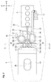
FIG. 3 is a plane view of the same. -
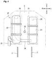
FIG. 4 is a schematic cross-sectional view along the arrow X-X illustrated inFIG. 3 . -
FIG. 5 is a left side view illustrating the configuration inside the bonnet according to another embodiment of the present invention. - In the following, the "up," "down," 'front," "forward," "back," "backward," "left," and "right" directions, respectively, are directions with respect to the travelling direction of a work vehicle. These directions are denoted by the arrow U for "up", the arrow D for "down", the arrow F for "front" and "forward", the arrow B for "back" and "backward", the arrow L for "left", and the arrow R for "right" in the drawings.
- Referring to
FIG. 1 , a general configuration of atractor 1, which is an example of a work vehicle according to the present invention, will be described. - The
tractor 1 mainly includes avehicle body frame 2,front wheels rear wheels engine 5, abonnet 6, atransmission 7, asteering wheel 8, and aseat 9. - The
vehicle body frame 2 is disposed with a longitudinal axis thereof oriented along the front-back direction. A front portion of thevehicle body frame 2 is supported by a pair of right and leftfront wheels transmission 7 is arranged on a rear portion of thevehicle body frame 2. A rear portion of thetransmission 7 is supported by a pair of right and leftrear wheels engine 5 such as a diesel engine is arranged on the front portion of thevehicle body frame 2. Theengine 5 is covered by thebonnet 6. Thebonnet 6 is formed such that an upper side plate is inclined in the downward direction along the forward direction, and gradually decreases in width in the up-down direction along the forward direction. - A drive force of the
engine 5 is transmitted by thetransmission 7 to thefront wheels rear wheels engine 5 rotates thefront wheels rear wheels tractor 1. - A driving operation section includes the
steering wheel 8, various operational tools, theseat 9, and the like. The driving operation is disposed at the back of theengine 5. - The
steering wheel 8 adjusts (varies) a steering angle of thefront wheels tractor 1. - Referring to
FIGS. 2 to 4 , layouts of various members inside thebonnet 6 will be described. - Inside the
bonnet 6, theengine 5, aturbocharger 11, anexhaust gas purifier 20, aradiator fan 31, ashaft 32, aradiator 33, anair cleaner 34, aleft shielding plate 35, aright shielding plate 36, and the like are disposed. - The
engine 5 is disposed in a rear portion of thebonnet 6. Theengine 5 is supported by thevehicle body frame 2. - The
turbocharger 11 is configured to feed compressed air to a cylinder (not illustrated) of theengine 5. Theturbocharger 11 is attached to a left upper end portion of a front-back midway section of theengine 5. Theturbocharger 11 is connected to an intake manifold (not illustrated) and an exhaust manifold (not illustrated) of theengine 5. Exhaust gas flows into theturbocharger 11 from the exhaust manifold. Theturbocharger 11 rotates a turbine using the entered exhaust gas, thereby feeding the compressed air from the intake manifold to the cylinder. - The
exhaust gas purifier 20 is configured to purify and discharge the exhaust gas. Theexhaust gas purifier 20 is disposed in a front-back midway section of thebonnet 6. Theexhaust gas purifier 20 is provided with a diesel particulate filter (DPF) 21, a selective catalytic reduction device (SCR) 22, aninflow pipe 23, a connectingpipe 24, a reducingagent supply nozzle 25, and amuffler 26. - The
DPF 21 is configured to collect particulate matter (PM) contained in the exhaust gas discharged from theengine 5. TheDPF 21 is provided with a filter or the like to collect PM in a substantially cylindrical case (housing). TheDPF 21 is disposed with its longitudinal axis oriented along the up-down direction. TheDPF 21 is formed such that the height thereof along the up-down direction is smaller than the height along the up-down direction of theengine 5. TheDPF 21 is disposed in front of theengine 5 on the left side, namely in front of theturbocharger 11. - The
SCR 22 is configured to purify nitrogen oxides contained in the exhaust gas. TheSCR 22 has a cylindrical case as a housing accommodating a catalyst and the like therein. TheSCR 22 is disposed with its longitudinal axis oriented along the up-down direction. TheSCR 22 is formed such that the height along the up-down direction is larger than the height along the up-down direction of theDPF 21, and is smaller than the height along the up-down direction of theengine 5. TheSCR 22 is formed such that a width thereof along the front-back direction is narrower than a width of theDPF 21 along the front-back direction. TheSCR 22 is disposed in front of theengine 5 on the right side, namely next to theDPF 21 on its right side. TheSCR 22 is spaced away from theDPF 21 with a gap along the right-left direction between itself and theDPF 21. - The
inflow pipe 23 is configured to guide the exhaust gas to theDPF 21. One end portion of theinflow pipe 23, i.e. the intake end portion, is connected to a rear end portion of theturbocharger 11. Theinflow pipe 23 extends backwards along the front-back direction from the other end portion, i.e. the outlet end portion. The intake end portion bends back so as to extend further forward from the turning point. The intake end portion is connected to theturbocharger 11. The outlet end portion of theinflow pipe 23 is connected to an exhaust gas inlet (not illustrated) formed on a upper end portion of theDPF 21 on its back side. - The connecting
pipe 24 is configured to guide the exhaust gas that has passed through theDPF 21 to theSCR 22. One end portion of the connectingpipe 24, i.e. the intake end portion, is connected to an exhaust gas outlet (not illustrated) formed on a lower end portion of theDPF 21 on its back side. The connectingpipe 24 extends from the intake end portion and bends at its midway towards an exhaust gas inlet (not illustrated) formed on an upper end portion of theSCR 22 on its back side. The other end portion of the connectingpipe 24, i.e. the outlet end portion, is connected to the exhaust gas inlet of theSCR 22. - The reducing
agent supply nozzle 25 is configured to inject a urea aqueous solution into the connectingpipe 24. The reducingagent supply nozzle 25 is arranged on the midway section of the connectingpipe 24. The reducingagent supply nozzle 25 is connected to a tank (not illustrated), and is configured to inject the urea aqueous solution stored in the tank into the connectingpipe 24. - The
muffler 26 is configured to discharge exhaust gas to the outside while reducing exhaust noise. One end portion of themuffler 26, i.e. the intake end portion, is connected to an exhaust gas outlet (not illustrated) formed on a lower end portion of theSCR 22 on its back side. A midway section of themuffler 26 appropriately bends. The other end portion of themuffler 26, i.e. the outlet end portion, opens to the outside of thebonnet 6. - In the
exhaust gas purifier 20 configured as described above, exhaust gas is guided to theDPF 21 via theturbocharger 11 and theinflow pipe 23. When the exhaust gas flows through theDPF 21, the PM contained in the exhaust gas is collected therein. - The exhaust gas that has passed through the
DPF 21 is guided to theSCR 22 via the connectingpipe 24. At this time, urea aqueous solution is injected from the reducingagent supply nozzle 25 into the exhaust gas that flows through the connectingpipe 24. The urea aqueous solution is hydrolyzed in the connectingpipe 24, producing ammonia, which is a reducing agent. The exhaust gas and the ammonia are sufficiently mixed in the connectingpipe 24. The ammonia chemically reacts with the nitrogen oxides contained in the exhaust gas in theSCR 22, and reduces the nitrogen oxides to nitrogen and water, which are harmless components. The exhaust gas that has passed through theSCR 22 is discharged to the outside via themuffler 26. - The
radiator fan 31 is configured to cool theradiator 33 described later. Theradiator fan 31 is disposed in front of theexhaust gas purifier 20. Theradiator fan 31 is driven by the drive force from theengine 5. Theradiator fan 31 suctions the ambient air in front of the radiator fan 31 (outside air that flows into the bonnet 6), and sends the suctioned air in the backward direction. - The
shaft 32 is configured to drive theradiator fan 31. Theshaft 32 is extends along the front-back direction. The front end portion of theshaft 32 is rotatably supported by abearing 32a, and connected to theradiator fan 31. Thebearing 32a is supported by thevehicle body frame 2 via a connectingmember 32b formed into a plate shape, and the like. The rear end portion of theshaft 32 is connected to an output shaft of theengine 5 via a fixing means such as a belt. As a result, theshaft 32 transmits the drive force of theengine 5 to theradiator fan 31. Theshaft 32 has, for example, two shaft-shaped members connected with each other by a universal joint (not illustrated), each having an axis disposed along a front-back direction. A front-back midway section of theshaft 32 is disposed between theDPF 21 and theSCR 22. Further, the front-back midway section of theshaft 32 extends above the connectingpipe 24. As a result, theshaft 32 extends between theDPF 21 and theSCR 22 to connect theengine 5 and theradiator fan 31. - The
radiator 33 is configured to cool the coolant of theengine 5. Theradiator 33 is disposed on the front portion of thebonnet 6, i.e. in front of theradiator fan 31. Theradiator 33 is inclined along the front-back direction such that the upper end of theradiator 33 is positioned at the back of the lower end of theradiator 33 in a plane view.
Theradiator 33 is connected to a water jacket (not illustrated) of theengine 5 via a hose and the like. Outside air that flows into the interior of thebonnet 6 passes through theradiator 33, thereby cooling the coolant of theengine 5. Theradiator 33 is provided with ashroud 33a for introducing the outside air into theradiator fan 31. Theshroud 33a is formed so as to extend from a rear portion of theradiator 33 toward theradiator fan 31. A rear end portion of theshroud 33a is formed so as to cover the outer periphery of theradiator fan 31. - The
air cleaner 34 purifies the outside air supplied to theengine 5. Theair cleaner 34 is disposed in front of and over the front-back midway section of theradiator 33. Theair cleaner 34 is disposed in the interior of thebonnet 6 in the same posture as that of theradiator 33. Theair cleaner 34, in its entirety, is disposed so as to overlap with theradiator 33 in a plane view and a front view. Theair cleaner 34 is connected to the intake manifold via theturbocharger 11. - The
left shielding plate 35 is configured to block wind that blows toward the DPF 21 (wind from theradiator fan 31, for example). Theleft shielding plate 35 is formed into a substantially J shape in a plane view. Theleft shielding plate 35 includes a plate-shapedmember 35a along the right-left direction and acurved portion 35b. The curved portion extends from the plate-shapedmember 35a and curves towards the backward direction. - The
flat portion 35a is a section formed so as to extend in the rightward direction from a left end portion of theleft shielding plate 35. Theflat portion 35a is disposed in front of theDPF 21. A left end portion of theflat portion 35a is disposed in a position that overlaps with a left end portion of theDPF 21 in the front view. - The
curved portion 35b is a section formed so as to extend from a right end portion of theflat portion 35a in the right backward direction (to theengine 5 side). Thecurved portion 35b is formed into a substantially arc shape in the plane view. A rear end portion of thecurved portion 35b is located on the right side of theDPF 21. - Such a
left shielding plate 35 is formed so that a height in the up-down direction is larger than the height in the up-down direction of theDPF 21. An upper end portion of theleft shielding plate 35 is located over an upper end portion of theDPF 21. Further, a lower end portion of theleft shielding plate 35 is located below a lower end portion of theDPF 21. As a result, theleft shielding plate 35 is formed so as to cover a front portion of theDPF 21. - The
right shielding plate 36 is configured to block wind that blows toward the SCR 22 (wind from theradiator fan 31, for example). Theright shielding plate 36 is formed so as to be substantially bilaterally symmetrical with theleft shielding plate 35. Theright shielding plate 36 has aflat portion 36a and acurved portion 36b that correspond to theflat portion 35a and thecurved portion 35b of theleft shielding plate 35. Theright shielding plate 36 is formed so as to cover a front portion of theSCR 22. - The
left shielding plate 35 and right shieldingplate 36 are, for example, fixed to thevehicle body frame 2 via a predetermined connecting member. Theleft shielding plate 35 and theright shielding plate 36 block the wind that blows toward theDPF 21 and theSCR 22, and make theDPF 21 and theSCR 22 less susceptible to wind exposure. Accordingly, theDPF 21 and theSCR 22 are less susceptible to being cooled by the wind that blows toward theDPF 21 and theSCR 22. Thus, theleft shielding plate 35 and theright shielding plate 36 can suppress temperature decreases in theDPF 21 and theSCR 22. As a result, theleft shielding plate 35 and theright shielding plate 36 can suppress decreases in a regeneration efficiency of theDPF 21 and a catalytic reaction efficiency of theSCR 22. - As described above, the
DPF 21 and theSCR 22 are disposed in front of theengine 5. As a result, in thetractor 1, the rear portion which is the highest section of thebonnet 6 can be lowered. Thereby the height of theoverall bonnet 6 can be decreased. - Accordingly, the
bonnet 6 is less likely to contact with tree branches, fruits on the branches, and the like when thetractor 1 passes under the tree branches and fruits thereon. Further, a decrease in the height of thebonnet 6 makes it possible to maintain a field of vision in front of the driver on the downside. - Further, in the
tractor 1, theDPF 21 and theSCR 22 are disposed in front of theengine 5. Thereby, the width in the right-left direction of thebonnet 6 is reduced at the portion where theengine 5, theDPF 21 and theSCR 22 are disposed. Further, this configuration enables to maintain the field of vision in front of the driver on his left and right side. - Further, the
DPF 21 and theSCR 22 are disposed side by side along the right-left direction. Thereby, in thetractor 1, the length of theexhaust gas purifier 20 along the front-back direction is reduced. Furthermore, the length of thebonnet 6 along the front-back direction is reduced. - When the
DPF 21 and theSCR 22 are disposed in front of theengine 5 as in the present embodiment, the length ofbonnet 6 along the front-back direction might increase. This possibly results in deterioration in a turning performance of thetractor 1. However, even in such a case, the above configuration where theDPF 21 and theSCR 22 are disposed side by side in thetractor 1 along the right-left direction can prevent the length of thebonnet 6 from being increased more than necessary. Thereby the deterioration in the turning performance is suppressed. - Further, the
DPF 21 and theSCR 22 are disposed such that their longitudinal axes are oriented along the up-down direction. Accordingly, in thetractor 1, it is possible to decrease the length of thebonnet 6 along the front-back direction as well as the width of the bonnet 6along the right-left direction. - The
radiator 33 is disposed in front of theDPF 21 and theSCR 22. Thereby the outside air, which flows from outside into the interior of thebonnet 6, passes through theradiator 33 and then blows against theDPF 21 and theSCR 22. Accordingly, the outside air with a low temperature (the state before taking in the heat from theDPF 21 and the like and being increased in temperature) can pass through theradiator 33. Thereby the coolant of theengine 5 can be effectively cooled down with the outside air. Accordingly, theradiator 3 can suppress a decrease in a cooling efficiency of the coolant. - The
radiator 33 is inclined along the front-back direction such that the upper end of theradiator 33 is positioned at the back of the lower end of theradiator 33 in a plane view. Thereby the actual height of theradiator 33 is reduced under thebonnet 6 along the up-down direction. The actual height of theradiator 33 is a difference in the height of an upper end portion and the height of the lower end portion of theradiator 33 with respect to the up-down direction. Such a posture makes it possible to decrease the height of the space for arranging theradiator 33 within the space under thebonnet 6. Thereby the height of the space under thebonnet 6 is decreased and the front portion of thebonnet 6 can be lowered. Further, such a posture of theradiator 33 enables itself to be accommodated under the front portion of thebonnet 6 even if the front portion of thebonnet 6 is lowered. - Further, such a posture also allows the space under the
bonnet 6 to accommodate a larger radiator. As a result, the cooling efficiency of theengine 5 can be improved. - Here, when the
radiator 33 is inclined along the front-back direction such that the upper end of theradiator 33 is positioned at the back of the lower end of theradiator 33 in a plane view, a space is formed in front of and over theradiator 33. In addition, another space is formed at the back of and under theradiator 33. Theair cleaner 34 is disposed so as to overlap with theradiator 33 in the plane view and the front view. Accordingly, theair cleaner 34 is thus disposed in the space formed in front of and over theradiator 33. Accordingly, the inside space of thetractor 1 can be effectively utilized. - The
radiator fan 31 is disposed in front of theDPF 21 and theSCR 22. This configuration enables theradiator fan 31, which is located at a position closer to theradiator 33 than theDPF 21 and theSCR 22, to suction the outside air flowing into the space under thebonnet 6. As a result, theradiator fan 31 can effectively cool down theradiator 33. - The
shaft 32 extends between theDPF 21 and theSCR 22, connecting theengine 5 and theradiator fan 31. This configuration enables theshaft 32 to linearly connect theengine 5 and theradiator fan 31 without circumventing theDPF 21 and theSCR 22. As a result, the structure to drive theradiator fan 31 by theshaft 32 can be simplified. - It should be noted that the
tractor 1 according to the present embodiment is an embodiment of the work vehicle according to the present invention. Further, theleft shielding plate 35 and theright shielding plate 36 according to the present embodiment are embodiments of the shielding means according to the present invention. - In the present embodiment, the
DPF 21 and theSCR 22 are disposed at the back of theradiator fan 31. TheDPF 21 and theSCR 22 are preferably further disposed so as not to overlap with the centre portion of theengine 5 with respect to the right-left direction. More precisely, each of theDPF 21 and theSCR 22 is arranged either on the right side or the left side with respect to a virtual line extending along the front-back direction of thetractor 1. The virtual line extends through the centre of theengine 5 with respect to the right-left direction. As a result, the wind from theradiator fan 31 can be applied to the right-left centre portion of theengine 5. Thereby theengine 5 can be effectively cooled down by the wind. - The
left shielding plate 35 and theright shielding plate 36 are spaced out with a gap therebetween along the right-left direction. As a result, the wind that blows toward theDPF 21 and theSCR 22 flows through the gap along the backward direction and blows against theengine 5. This configuration enables theleft shielding plate 35 and theright shielding plate 36 to easily guide the wind towards theengine 5 while making theDPF 21 and theSCR 22 less susceptible to wind exposure. Theradiator fan 31 can thus reliably cool theengine 5 even when theDPF 21 and theSCR 22 are disposed between theradiator fan 31 and theengine 5. - The
left shielding plate 35 and theright shielding plate 36 have thecurved portions curved portions flat portions engine 5. Accordingly, theleft shielding plate 35 and theright shielding plate 36 can guide the wind that blows from theDPF 21 and theSCR 22 towards theengine 5. Thereby the cooling efficiency of theengine 5 by theradiator fan 31 can be improved. - While the above has described an embodiment of the present invention, the present invention is not limited to the above-described configuration, and various changes may be made within the scope of the invention set forth in the claims.
- For example, while the work vehicle according to the present embodiment is the
tractor 1, the type of work vehicle according to the present invention is not limited thereto. The work vehicle according to the present invention may be another agricultural vehicle, a construction vehicle, an industrial vehicle, or the like. The work vehicle according to the present invention is preferably applied to a folding-body type vehicle having excellent turning performance. - While the
DPF 21 and theSCR 22 in the present embodiment are disposed next to each other along the right-left direction, the arrangement of the DPF and the SCR is not limited thereto, and may be next to each other along the front-back direction. The DPF and the SCR are not necessarily disposed next to each other along the right-left direction or front-back direction. - While the
DPF 21 and theSCR 22 in the present embodiment are disposed with its longitudinal axis oriented along the up-down direction, the postures of the DPF and the SCR are not limited thereto. For example, the DPF and the SCR may be disposed in postures having their longitudinal axes oriented along the front-back direction or the right-left direction. - While the
DPF 21 in the above embodiment is disposed on the right side of theSCR 22, the arrangement of the DPF and the SCR is not limited thereto. For example, the DPF may be disposed on the left side of the SCR. - While the
DPF 21 and theSCR 22 in the above embodiment are disposed at the back of theradiator 33, the DPF and the SCR may be disposed in front of theradiator 33. - While the
shaft 32 is disposed along the front-back direction in the above embodiment, the configuration of the shaft is not limited thereto. For example,Fig. 5 shows another arrangement of ashaft 132 which is disposed along the front-back direction in a plan view and is inclined downwardly in a side view. The front end of theshaft 132 is located below the rear end thereof. The front end portion and the rear end portion of theshaft 132 are connected to the output shaft of theengine 5 and aradiator fan 131 via a universal joint 132c, respectively. - Offsetting properly the
shaft 132 along the up-down direction in the above manner enables theradiator fan 131 to be aligned with a centre of theradiator 33, for example. Thus the cooling efficiency of theradiator fan 131 can be improved. Furthermore, theradiator fan 131 can be accommodated in the space formed under theradiator 33 on its back side. Thereby the space inside the working vehicle can be effectively utilised. This leads to downsizing of ashroud 133a along the right-left direction and further leads to downsizing of thebonnet 6 in its front-back direction. - While the
radiator 33 in the above embodiment is inclined along the front-back direction such that the upper end of theradiator 33 is positioned at the back of the lower end of theradiator 33 in a plane view, the posture of the radiator is not limited thereto. For example, a radiator may have a posture extending in the up-down direction. This holds true for theair cleaner 34 as well. - While the
air cleaner 34 in the embodiment above entirely overlaps with theradiator 33 in the front view and the plane view, the positional relationship between the air cleaner and the radiator is not limited thereto. For example, the air cleaner may overlap with theradiator 33 only partially such as in a rear end portion thereof, and/or in the front view and the plane view. - While the
left shielding plate 35 and theright shielding plate 36 in the embodiment above are each formed into a substantially J shape in the plane view, the shape of the shielding means is not limited thereto. For example, the shielding means may be substantially U shaped in the plane view so as to cover theDPF 21 and theSCR 22 from its front end portion to a front-back centre portion. Another shape of the shielding means would be a flat-plate shape with the plate surface oriented along the front-back direction. The shielding means may be provided with a heat insulating material that covers theDPF 21 and theSCR 22. - While the
DPF 21 and theSCR 22 are less susceptible to exposure to wind from theradiator fan 31 due to theleft shielding plate 35 and theright shielding plate 36 in the embodiment above, the shielding means may make at least one of theDPF 21 and theSCR 22 less susceptible to exposure to wind from theradiator fan 31. - While the
left shielding plate 35 and theright shielding plate 36 keep the front portion of each of theDPF 21 and theSCR 22 less susceptible to exposure to wind from theradiator fan 31, the configuration of the shielding means is not limited thereto. For example, the shielding means may cover the entire periphery of theDPF 21, which keeps theDPF 21 in its entirety less susceptible to exposure to wind from theradiator fan 31. - The configuration of the
DPF 21 and theSCR 22 is not limited to that in the embodiment above. For example, a diesel oxidation catalyst (DOC) may be further disposed on an upstream side of the filter of theDPF 21.
The reducing agent used in theSCR 22 is not limited to ammonia. -
- 1 Tractor (work vehicle)
- 5 Engine
- 6 Bonnet
- 21 DPF
- 22 SCR
Claims (15)
- A work vehicle (1) comprising:a driver's seat (9);a bonnet (6) disposed forward of the seat; andan engine (5) arranged under the bonnet;characterised in thata diesel particulate filter (21) and an selective catalytic reduction (22) configured to purify an exhaust gas of the engine, the diesel particulate filter and the selective catalytic reduction being arranged under the bonnet and forward of the engine.
- The work vehicle (1) according to claim 1, wherein
the diesel particulate filter (21) and the selective catalytic reduction (22) are disposed side by side along the width direction of the work vehicle. - The work vehicle (1) according to claim 1 or 2, wherein
at least one of the diesel particulate filter (21) and the selective catalytic reduction (22) has a shape elongated along one dimension; and
the diesel particulate filter and/or the selective catalytic reduction are disposed such that the longitudinal dimension of at least one of the diesel particulate filter and the selective catalytic reduction is oriented along an up-down direction of the work vehicle. - The work vehicle (1) according to any one of claims 1 to 3, further comprising:a radiator (33) configured to cool a coolant of the engine (5), the radiator being disposed under the bonnet (6) and forward of the diesel particulate filter (21) and the selective catalytic reduction (22).
- The work vehicle (1) according to claim 4, wherein
the radiator (33) is inclined along a front-back direction of the work vehicle. - The work vehicle (1) according to claim 5, wherein
the radiator (33) is inclined along the front-back direction such that the upper end of the radiator (33) is positioned at the back of the lower end of the radiator (33) in a plane view. - The work vehicle (1) according to any one of claims 4 to 6, further comprising
an air cleaner (34) configured to purify the ambient air to be supplied to the engine (5), the air cleaner being disposed under the bonnet (6) such that at least a portion thereof overlaps with the radiator in a plan view and a front view. - The work vehicle (1) according to any one of claims 4 to 7, further comprising:a radiator fan (31) configured to be driven by the engine (5) and cool the radiator (33), the radiator fan being disposed between the radiator and both the diesel particulate filter (21) and the selective catalytic reduction (22).
- The work vehicle (1) according to claim 8, further comprising:a shaft (32) connecting the engine (5) and the radiator fan (31) and linearly extending between the diesel particulate filter (21) and the selective catalytic reduction (22), and configured to transmit a drive force of the engine to the radiator fan.
- The work vehicle (1) according to any one of claims 1 to 8, further comprising:a shielding means (35, 36) disposed under the bonnet (6) and configured to at least partially shield wind towards at least one of the diesel particulate filter (21) and the selective catalytic reduction (22).
- The work vehicle (1) according to claim 10, wherein
the shielding means (35, 36) is configured to surround at least the front side of at least one of the diesel particulate filter (21) and the selective catalytic reduction (22). - The work vehicle (1) according to any one of claims 1 to 11, wherein
the diesel particulate filter (21) and the selective catalytic reduction (22) are arranged to form a passage of wind such that the passage linearly extends toward the engine (5). - The work vehicle (1) according to claim 12,
each of the diesel particulate filter (21) and the selective catalytic reduction (22) is arranged either on the right side or the left side with respect to a virtual line extending along the front-back direction of the work vehicle, the virtual line further extending through the centre of the engine (5) with respect to width direction of the work vehicle. - The work vehicle (1) according to claim 12 or 13, further comprising:first and second shielding members (35, 36) disposed under the bonnet (6);the first shielding member (35) surrounding at least the front side of the diesel particulate filter (21), andthe second shielding member (36) surrounding at least the front side of the selective catalytic reduction (22).
- The work vehicle (1) according to claim 12, 13 or 14, wherein
the first shielding member (35) and the second shielding member (36) form a passage of wind such that the passage linearly extends toward the engine (5) and between the first and second shielding members.
Applications Claiming Priority (1)
| Application Number | Priority Date | Filing Date | Title |
|---|---|---|---|
| JP2015123712A JP6421084B2 (en) | 2015-06-19 | 2015-06-19 | Work vehicle |
Publications (2)
| Publication Number | Publication Date |
|---|---|
| EP3109085A1 true EP3109085A1 (en) | 2016-12-28 |
| EP3109085B1 EP3109085B1 (en) | 2019-02-20 |
Family
ID=54186645
Family Applications (1)
| Application Number | Title | Priority Date | Filing Date |
|---|---|---|---|
| EP16170022.4A Active EP3109085B1 (en) | 2015-06-19 | 2016-05-17 | Work vehicle |
Country Status (3)
| Country | Link |
|---|---|
| EP (1) | EP3109085B1 (en) |
| JP (1) | JP6421084B2 (en) |
| ES (1) | ES2720350T3 (en) |
Cited By (1)
| Publication number | Priority date | Publication date | Assignee | Title |
|---|---|---|---|---|
| EP3591211A2 (en) | 2018-06-15 | 2020-01-08 | Kubota Corporation | Work vehicle |
Families Citing this family (3)
| Publication number | Priority date | Publication date | Assignee | Title |
|---|---|---|---|---|
| JP6421084B2 (en) * | 2015-06-19 | 2018-11-07 | 株式会社クボタ | Work vehicle |
| JP7445559B2 (en) * | 2020-08-27 | 2024-03-07 | 三菱マヒンドラ農機株式会社 | work vehicle |
| JP7562438B2 (en) | 2021-02-04 | 2024-10-07 | 三菱マヒンドラ農機株式会社 | Riding rice transplanter |
Citations (4)
| Publication number | Priority date | Publication date | Assignee | Title |
|---|---|---|---|---|
| JP2014105549A (en) | 2012-11-29 | 2014-06-09 | Yanmar Co Ltd | Engine device |
| WO2014157285A1 (en) * | 2013-03-28 | 2014-10-02 | ヤンマー株式会社 | Engine device for work vehicles |
| JP2014190328A (en) * | 2013-03-28 | 2014-10-06 | Yanmar Co Ltd | Engine device |
| JP2015163512A (en) * | 2015-06-19 | 2015-09-10 | 株式会社クボタ | work vehicle |
Family Cites Families (4)
| Publication number | Priority date | Publication date | Assignee | Title |
|---|---|---|---|---|
| JPS52137430U (en) * | 1976-04-13 | 1977-10-19 | ||
| JP2007137195A (en) * | 2005-11-16 | 2007-06-07 | Calsonic Kansei Corp | Arrangement structure of cooling system in engine room |
| JP2012219624A (en) * | 2011-04-04 | 2012-11-12 | Hitachi Constr Mach Co Ltd | Construction machine |
| JP5336647B1 (en) * | 2012-12-20 | 2013-11-06 | 株式会社小松製作所 | Work vehicle |
-
2015
- 2015-06-19 JP JP2015123712A patent/JP6421084B2/en active Active
-
2016
- 2016-05-17 EP EP16170022.4A patent/EP3109085B1/en active Active
- 2016-05-17 ES ES16170022T patent/ES2720350T3/en active Active
Patent Citations (4)
| Publication number | Priority date | Publication date | Assignee | Title |
|---|---|---|---|---|
| JP2014105549A (en) | 2012-11-29 | 2014-06-09 | Yanmar Co Ltd | Engine device |
| WO2014157285A1 (en) * | 2013-03-28 | 2014-10-02 | ヤンマー株式会社 | Engine device for work vehicles |
| JP2014190328A (en) * | 2013-03-28 | 2014-10-06 | Yanmar Co Ltd | Engine device |
| JP2015163512A (en) * | 2015-06-19 | 2015-09-10 | 株式会社クボタ | work vehicle |
Cited By (1)
| Publication number | Priority date | Publication date | Assignee | Title |
|---|---|---|---|---|
| EP3591211A2 (en) | 2018-06-15 | 2020-01-08 | Kubota Corporation | Work vehicle |
Also Published As
| Publication number | Publication date |
|---|---|
| ES2720350T3 (en) | 2019-07-19 |
| JP2015163512A (en) | 2015-09-10 |
| JP6421084B2 (en) | 2018-11-07 |
| EP3109085B1 (en) | 2019-02-20 |
Similar Documents
| Publication | Publication Date | Title |
|---|---|---|
| US8505661B2 (en) | Work vehicle with engine compartment and exhaust gas treatment arrangement | |
| US8967319B2 (en) | Horizontal muffler for an agricultural vehicle | |
| JP5688167B2 (en) | Construction machinery | |
| KR101579213B1 (en) | Exhaust gas aftertreatment unit, and construction vehicle equipped with same | |
| EP3109085B1 (en) | Work vehicle | |
| EP3173537B1 (en) | Engine compartment of a work vehicle | |
| JP5956373B2 (en) | Engine device for work vehicle | |
| KR20250070136A (en) | Working vehicle | |
| JP6295195B2 (en) | Work machine | |
| WO2014157286A1 (en) | Engine device | |
| EP2837516B1 (en) | Utility vehicle | |
| WO2014069038A1 (en) | Dumptruck | |
| KR20150132134A (en) | Engine device | |
| KR102183434B1 (en) | tractor | |
| KR20160096586A (en) | Working vehicle | |
| US9540979B2 (en) | Working vehicle | |
| KR20180138159A (en) | Combine | |
| JP6162519B2 (en) | Tractor | |
| JP2011106311A (en) | Engine device to be mounted on working vehicle | |
| JP6161057B2 (en) | Exhaust gas purification device | |
| JP2020148203A (en) | Tractor | |
| KR101578337B1 (en) | Hydraulic shovel | |
| WO2015012169A1 (en) | Working vehicle |
Legal Events
| Date | Code | Title | Description |
|---|---|---|---|
| PUAI | Public reference made under article 153(3) epc to a published international application that has entered the european phase |
Free format text: ORIGINAL CODE: 0009012 |
|
| STAA | Information on the status of an ep patent application or granted ep patent |
Free format text: STATUS: THE APPLICATION HAS BEEN PUBLISHED |
|
| AK | Designated contracting states |
Kind code of ref document: A1 Designated state(s): AL AT BE BG CH CY CZ DE DK EE ES FI FR GB GR HR HU IE IS IT LI LT LU LV MC MK MT NL NO PL PT RO RS SE SI SK SM TR |
|
| AX | Request for extension of the european patent |
Extension state: BA ME |
|
| STAA | Information on the status of an ep patent application or granted ep patent |
Free format text: STATUS: REQUEST FOR EXAMINATION WAS MADE |
|
| 17P | Request for examination filed |
Effective date: 20170303 |
|
| RBV | Designated contracting states (corrected) |
Designated state(s): AL AT BE BG CH CY CZ DE DK EE ES FI FR GB GR HR HU IE IS IT LI LT LU LV MC MK MT NL NO PL PT RO RS SE SI SK SM TR |
|
| GRAP | Despatch of communication of intention to grant a patent |
Free format text: ORIGINAL CODE: EPIDOSNIGR1 |
|
| STAA | Information on the status of an ep patent application or granted ep patent |
Free format text: STATUS: GRANT OF PATENT IS INTENDED |
|
| INTG | Intention to grant announced |
Effective date: 20181203 |
|
| GRAS | Grant fee paid |
Free format text: ORIGINAL CODE: EPIDOSNIGR3 |
|
| GRAA | (expected) grant |
Free format text: ORIGINAL CODE: 0009210 |
|
| STAA | Information on the status of an ep patent application or granted ep patent |
Free format text: STATUS: THE PATENT HAS BEEN GRANTED |
|
| AK | Designated contracting states |
Kind code of ref document: B1 Designated state(s): AL AT BE BG CH CY CZ DE DK EE ES FI FR GB GR HR HU IE IS IT LI LT LU LV MC MK MT NL NO PL PT RO RS SE SI SK SM TR |
|
| REG | Reference to a national code |
Ref country code: GB Ref legal event code: FG4D |
|
| REG | Reference to a national code |
Ref country code: CH Ref legal event code: EP |
|
| REG | Reference to a national code |
Ref country code: DE Ref legal event code: R096 Ref document number: 602016010008 Country of ref document: DE |
|
| REG | Reference to a national code |
Ref country code: AT Ref legal event code: REF Ref document number: 1097711 Country of ref document: AT Kind code of ref document: T Effective date: 20190315 |
|
| REG | Reference to a national code |
Ref country code: IE Ref legal event code: FG4D |
|
| REG | Reference to a national code |
Ref country code: LT Ref legal event code: MG4D |
|
| REG | Reference to a national code |
Ref country code: ES Ref legal event code: FG2A Ref document number: 2720350 Country of ref document: ES Kind code of ref document: T3 Effective date: 20190719 |
|
| REG | Reference to a national code |
Ref country code: NL Ref legal event code: MP Effective date: 20190220 |
|
| PG25 | Lapsed in a contracting state [announced via postgrant information from national office to epo] |
Ref country code: PT Free format text: LAPSE BECAUSE OF FAILURE TO SUBMIT A TRANSLATION OF THE DESCRIPTION OR TO PAY THE FEE WITHIN THE PRESCRIBED TIME-LIMIT Effective date: 20190620 Ref country code: LT Free format text: LAPSE BECAUSE OF FAILURE TO SUBMIT A TRANSLATION OF THE DESCRIPTION OR TO PAY THE FEE WITHIN THE PRESCRIBED TIME-LIMIT Effective date: 20190220 Ref country code: NO Free format text: LAPSE BECAUSE OF FAILURE TO SUBMIT A TRANSLATION OF THE DESCRIPTION OR TO PAY THE FEE WITHIN THE PRESCRIBED TIME-LIMIT Effective date: 20190520 Ref country code: SE Free format text: LAPSE BECAUSE OF FAILURE TO SUBMIT A TRANSLATION OF THE DESCRIPTION OR TO PAY THE FEE WITHIN THE PRESCRIBED TIME-LIMIT Effective date: 20190220 Ref country code: FI Free format text: LAPSE BECAUSE OF FAILURE TO SUBMIT A TRANSLATION OF THE DESCRIPTION OR TO PAY THE FEE WITHIN THE PRESCRIBED TIME-LIMIT Effective date: 20190220 |
|
| PG25 | Lapsed in a contracting state [announced via postgrant information from national office to epo] |
Ref country code: BG Free format text: LAPSE BECAUSE OF FAILURE TO SUBMIT A TRANSLATION OF THE DESCRIPTION OR TO PAY THE FEE WITHIN THE PRESCRIBED TIME-LIMIT Effective date: 20190520 Ref country code: GR Free format text: LAPSE BECAUSE OF FAILURE TO SUBMIT A TRANSLATION OF THE DESCRIPTION OR TO PAY THE FEE WITHIN THE PRESCRIBED TIME-LIMIT Effective date: 20190521 Ref country code: RS Free format text: LAPSE BECAUSE OF FAILURE TO SUBMIT A TRANSLATION OF THE DESCRIPTION OR TO PAY THE FEE WITHIN THE PRESCRIBED TIME-LIMIT Effective date: 20190220 Ref country code: IS Free format text: LAPSE BECAUSE OF FAILURE TO SUBMIT A TRANSLATION OF THE DESCRIPTION OR TO PAY THE FEE WITHIN THE PRESCRIBED TIME-LIMIT Effective date: 20190620 Ref country code: LV Free format text: LAPSE BECAUSE OF FAILURE TO SUBMIT A TRANSLATION OF THE DESCRIPTION OR TO PAY THE FEE WITHIN THE PRESCRIBED TIME-LIMIT Effective date: 20190220 Ref country code: HR Free format text: LAPSE BECAUSE OF FAILURE TO SUBMIT A TRANSLATION OF THE DESCRIPTION OR TO PAY THE FEE WITHIN THE PRESCRIBED TIME-LIMIT Effective date: 20190220 Ref country code: NL Free format text: LAPSE BECAUSE OF FAILURE TO SUBMIT A TRANSLATION OF THE DESCRIPTION OR TO PAY THE FEE WITHIN THE PRESCRIBED TIME-LIMIT Effective date: 20190220 |
|
| REG | Reference to a national code |
Ref country code: AT Ref legal event code: MK05 Ref document number: 1097711 Country of ref document: AT Kind code of ref document: T Effective date: 20190220 |
|
| PG25 | Lapsed in a contracting state [announced via postgrant information from national office to epo] |
Ref country code: RO Free format text: LAPSE BECAUSE OF FAILURE TO SUBMIT A TRANSLATION OF THE DESCRIPTION OR TO PAY THE FEE WITHIN THE PRESCRIBED TIME-LIMIT Effective date: 20190220 Ref country code: SK Free format text: LAPSE BECAUSE OF FAILURE TO SUBMIT A TRANSLATION OF THE DESCRIPTION OR TO PAY THE FEE WITHIN THE PRESCRIBED TIME-LIMIT Effective date: 20190220 Ref country code: CZ Free format text: LAPSE BECAUSE OF FAILURE TO SUBMIT A TRANSLATION OF THE DESCRIPTION OR TO PAY THE FEE WITHIN THE PRESCRIBED TIME-LIMIT Effective date: 20190220 Ref country code: AL Free format text: LAPSE BECAUSE OF FAILURE TO SUBMIT A TRANSLATION OF THE DESCRIPTION OR TO PAY THE FEE WITHIN THE PRESCRIBED TIME-LIMIT Effective date: 20190220 Ref country code: DK Free format text: LAPSE BECAUSE OF FAILURE TO SUBMIT A TRANSLATION OF THE DESCRIPTION OR TO PAY THE FEE WITHIN THE PRESCRIBED TIME-LIMIT Effective date: 20190220 Ref country code: EE Free format text: LAPSE BECAUSE OF FAILURE TO SUBMIT A TRANSLATION OF THE DESCRIPTION OR TO PAY THE FEE WITHIN THE PRESCRIBED TIME-LIMIT Effective date: 20190220 |
|
| REG | Reference to a national code |
Ref country code: DE Ref legal event code: R097 Ref document number: 602016010008 Country of ref document: DE |
|
| PG25 | Lapsed in a contracting state [announced via postgrant information from national office to epo] |
Ref country code: SM Free format text: LAPSE BECAUSE OF FAILURE TO SUBMIT A TRANSLATION OF THE DESCRIPTION OR TO PAY THE FEE WITHIN THE PRESCRIBED TIME-LIMIT Effective date: 20190220 Ref country code: PL Free format text: LAPSE BECAUSE OF FAILURE TO SUBMIT A TRANSLATION OF THE DESCRIPTION OR TO PAY THE FEE WITHIN THE PRESCRIBED TIME-LIMIT Effective date: 20190220 |
|
| REG | Reference to a national code |
Ref country code: DE Ref legal event code: R119 Ref document number: 602016010008 Country of ref document: DE |
|
| PLBE | No opposition filed within time limit |
Free format text: ORIGINAL CODE: 0009261 |
|
| STAA | Information on the status of an ep patent application or granted ep patent |
Free format text: STATUS: NO OPPOSITION FILED WITHIN TIME LIMIT |
|
| REG | Reference to a national code |
Ref country code: CH Ref legal event code: PL |
|
| PG25 | Lapsed in a contracting state [announced via postgrant information from national office to epo] |
Ref country code: AT Free format text: LAPSE BECAUSE OF FAILURE TO SUBMIT A TRANSLATION OF THE DESCRIPTION OR TO PAY THE FEE WITHIN THE PRESCRIBED TIME-LIMIT Effective date: 20190220 |
|
| 26N | No opposition filed |
Effective date: 20191121 |
|
| PG25 | Lapsed in a contracting state [announced via postgrant information from national office to epo] |
Ref country code: MC Free format text: LAPSE BECAUSE OF FAILURE TO SUBMIT A TRANSLATION OF THE DESCRIPTION OR TO PAY THE FEE WITHIN THE PRESCRIBED TIME-LIMIT Effective date: 20190220 Ref country code: LI Free format text: LAPSE BECAUSE OF NON-PAYMENT OF DUE FEES Effective date: 20190531 Ref country code: CH Free format text: LAPSE BECAUSE OF NON-PAYMENT OF DUE FEES Effective date: 20190531 |
|
| REG | Reference to a national code |
Ref country code: BE Ref legal event code: MM Effective date: 20190531 |
|
| PG25 | Lapsed in a contracting state [announced via postgrant information from national office to epo] |
Ref country code: SI Free format text: LAPSE BECAUSE OF FAILURE TO SUBMIT A TRANSLATION OF THE DESCRIPTION OR TO PAY THE FEE WITHIN THE PRESCRIBED TIME-LIMIT Effective date: 20190220 Ref country code: LU Free format text: LAPSE BECAUSE OF NON-PAYMENT OF DUE FEES Effective date: 20190517 |
|
| PG25 | Lapsed in a contracting state [announced via postgrant information from national office to epo] |
Ref country code: TR Free format text: LAPSE BECAUSE OF FAILURE TO SUBMIT A TRANSLATION OF THE DESCRIPTION OR TO PAY THE FEE WITHIN THE PRESCRIBED TIME-LIMIT Effective date: 20190220 |
|
| PG25 | Lapsed in a contracting state [announced via postgrant information from national office to epo] |
Ref country code: IE Free format text: LAPSE BECAUSE OF NON-PAYMENT OF DUE FEES Effective date: 20190517 Ref country code: DE Free format text: LAPSE BECAUSE OF NON-PAYMENT OF DUE FEES Effective date: 20191203 |
|
| PG25 | Lapsed in a contracting state [announced via postgrant information from national office to epo] |
Ref country code: BE Free format text: LAPSE BECAUSE OF NON-PAYMENT OF DUE FEES Effective date: 20190531 |
|
| GBPC | Gb: european patent ceased through non-payment of renewal fee |
Effective date: 20200517 |
|
| PG25 | Lapsed in a contracting state [announced via postgrant information from national office to epo] |
Ref country code: GB Free format text: LAPSE BECAUSE OF NON-PAYMENT OF DUE FEES Effective date: 20200517 |
|
| PG25 | Lapsed in a contracting state [announced via postgrant information from national office to epo] |
Ref country code: CY Free format text: LAPSE BECAUSE OF FAILURE TO SUBMIT A TRANSLATION OF THE DESCRIPTION OR TO PAY THE FEE WITHIN THE PRESCRIBED TIME-LIMIT Effective date: 20190220 |
|
| PG25 | Lapsed in a contracting state [announced via postgrant information from national office to epo] |
Ref country code: HU Free format text: LAPSE BECAUSE OF FAILURE TO SUBMIT A TRANSLATION OF THE DESCRIPTION OR TO PAY THE FEE WITHIN THE PRESCRIBED TIME-LIMIT; INVALID AB INITIO Effective date: 20160517 Ref country code: MT Free format text: LAPSE BECAUSE OF FAILURE TO SUBMIT A TRANSLATION OF THE DESCRIPTION OR TO PAY THE FEE WITHIN THE PRESCRIBED TIME-LIMIT Effective date: 20190220 |
|
| PG25 | Lapsed in a contracting state [announced via postgrant information from national office to epo] |
Ref country code: MK Free format text: LAPSE BECAUSE OF FAILURE TO SUBMIT A TRANSLATION OF THE DESCRIPTION OR TO PAY THE FEE WITHIN THE PRESCRIBED TIME-LIMIT Effective date: 20190220 |
|
| REG | Reference to a national code |
Ref country code: FR Ref legal event code: PLFP Year of fee payment: 8 |
|
| PGFP | Annual fee paid to national office [announced via postgrant information from national office to epo] |
Ref country code: ES Payment date: 20250602 Year of fee payment: 10 |
|
| PGFP | Annual fee paid to national office [announced via postgrant information from national office to epo] |
Ref country code: IT Payment date: 20250422 Year of fee payment: 10 |
|
| PGFP | Annual fee paid to national office [announced via postgrant information from national office to epo] |
Ref country code: FR Payment date: 20250401 Year of fee payment: 10 |