EP3108922B1 - Systems for providing an antiseptic applicator - Google Patents
Systems for providing an antiseptic applicator Download PDFInfo
- Publication number
- EP3108922B1 EP3108922B1 EP16178801.3A EP16178801A EP3108922B1 EP 3108922 B1 EP3108922 B1 EP 3108922B1 EP 16178801 A EP16178801 A EP 16178801A EP 3108922 B1 EP3108922 B1 EP 3108922B1
- Authority
- EP
- European Patent Office
- Prior art keywords
- reservoir
- applicator
- antiseptic
- handle
- membrane
- Prior art date
- Legal status (The legal status is an assumption and is not a legal conclusion. Google has not performed a legal analysis and makes no representation as to the accuracy of the status listed.)
- Active
Links
- 230000002421 anti-septic effect Effects 0.000 title description 60
- 239000012528 membrane Substances 0.000 claims description 60
- 239000004599 antimicrobial Substances 0.000 claims description 58
- 239000012530 fluid Substances 0.000 claims description 57
- 238000004891 communication Methods 0.000 claims description 11
- 230000008878 coupling Effects 0.000 claims description 10
- 238000010168 coupling process Methods 0.000 claims description 10
- 238000005859 coupling reaction Methods 0.000 claims description 10
- 230000004044 response Effects 0.000 claims description 4
- 238000000034 method Methods 0.000 description 23
- 239000000463 material Substances 0.000 description 10
- LFQSCWFLJHTTHZ-UHFFFAOYSA-N Ethanol Chemical compound CCO LFQSCWFLJHTTHZ-UHFFFAOYSA-N 0.000 description 9
- 235000019441 ethanol Nutrition 0.000 description 8
- 239000000645 desinfectant Substances 0.000 description 7
- 230000000845 anti-microbial effect Effects 0.000 description 5
- 239000006260 foam Substances 0.000 description 5
- 230000004913 activation Effects 0.000 description 4
- 239000000853 adhesive Substances 0.000 description 4
- 230000001070 adhesive effect Effects 0.000 description 4
- 239000003599 detergent Substances 0.000 description 4
- NOPFSRXAKWQILS-UHFFFAOYSA-N docosan-1-ol Chemical compound CCCCCCCCCCCCCCCCCCCCCCO NOPFSRXAKWQILS-UHFFFAOYSA-N 0.000 description 4
- 239000002861 polymer material Substances 0.000 description 4
- 238000002360 preparation method Methods 0.000 description 4
- 230000008569 process Effects 0.000 description 4
- 238000005201 scrubbing Methods 0.000 description 4
- 239000003795 chemical substances by application Substances 0.000 description 3
- 238000011109 contamination Methods 0.000 description 3
- 230000001419 dependent effect Effects 0.000 description 3
- 229920005570 flexible polymer Polymers 0.000 description 3
- PEDCQBHIVMGVHV-UHFFFAOYSA-N Glycerine Chemical compound OCC(O)CO PEDCQBHIVMGVHV-UHFFFAOYSA-N 0.000 description 2
- 239000003708 ampul Substances 0.000 description 2
- 239000000356 contaminant Substances 0.000 description 2
- 230000003247 decreasing effect Effects 0.000 description 2
- 230000000249 desinfective effect Effects 0.000 description 2
- 229960000735 docosanol Drugs 0.000 description 2
- 239000011888 foil Substances 0.000 description 2
- 238000003780 insertion Methods 0.000 description 2
- 230000037431 insertion Effects 0.000 description 2
- BDERNNFJNOPAEC-UHFFFAOYSA-N propan-1-ol Chemical compound CCCO BDERNNFJNOPAEC-UHFFFAOYSA-N 0.000 description 2
- 238000011012 sanitization Methods 0.000 description 2
- 125000006850 spacer group Chemical group 0.000 description 2
- 238000001356 surgical procedure Methods 0.000 description 2
- KUXUALPOSMRJSW-IFWQJVLJSA-N 2-[6-[[amino-[[amino-(4-chloroanilino)methylidene]amino]methylidene]amino]hexyl]-1-[amino-(4-chloroanilino)methylidene]guanidine;(2r,3s,4r,5r)-2,3,4,5,6-pentahydroxyhexanoic acid Chemical compound OC[C@@H](O)[C@@H](O)[C@H](O)[C@@H](O)C(O)=O.C1=CC(Cl)=CC=C1NC(=N)NC(=N)NCCCCCCNC(=N)NC(=N)NC1=CC=C(Cl)C=C1 KUXUALPOSMRJSW-IFWQJVLJSA-N 0.000 description 1
- OSDLLIBGSJNGJE-UHFFFAOYSA-N 4-chloro-3,5-dimethylphenol Chemical compound CC1=CC(O)=CC(C)=C1Cl OSDLLIBGSJNGJE-UHFFFAOYSA-N 0.000 description 1
- ZCYVEMRRCGMTRW-UHFFFAOYSA-N 7553-56-2 Chemical compound [I] ZCYVEMRRCGMTRW-UHFFFAOYSA-N 0.000 description 1
- 241000272525 Anas platyrhynchos Species 0.000 description 1
- 241000894006 Bacteria Species 0.000 description 1
- 229920000742 Cotton Polymers 0.000 description 1
- KFZMGEQAYNKOFK-UHFFFAOYSA-N Isopropanol Chemical compound CC(C)O KFZMGEQAYNKOFK-UHFFFAOYSA-N 0.000 description 1
- -1 PVP-1 Chemical compound 0.000 description 1
- RVGRUAULSDPKGF-UHFFFAOYSA-N Poloxamer Chemical compound C1CO1.CC1CO1 RVGRUAULSDPKGF-UHFFFAOYSA-N 0.000 description 1
- XEFQLINVKFYRCS-UHFFFAOYSA-N Triclosan Chemical compound OC1=CC(Cl)=CC=C1OC1=CC=C(Cl)C=C1Cl XEFQLINVKFYRCS-UHFFFAOYSA-N 0.000 description 1
- 238000005299 abrasion Methods 0.000 description 1
- 230000003213 activating effect Effects 0.000 description 1
- 239000003242 anti bacterial agent Substances 0.000 description 1
- 230000004888 barrier function Effects 0.000 description 1
- 230000009286 beneficial effect Effects 0.000 description 1
- 239000011111 cardboard Substances 0.000 description 1
- 229920006317 cationic polymer Polymers 0.000 description 1
- 229920002678 cellulose Polymers 0.000 description 1
- 239000001913 cellulose Substances 0.000 description 1
- 239000003153 chemical reaction reagent Substances 0.000 description 1
- 238000004140 cleaning Methods 0.000 description 1
- 230000006835 compression Effects 0.000 description 1
- 238000007906 compression Methods 0.000 description 1
- 230000001010 compromised effect Effects 0.000 description 1
- 230000006378 damage Effects 0.000 description 1
- 238000001804 debridement Methods 0.000 description 1
- 229940008099 dimethicone Drugs 0.000 description 1
- 239000004205 dimethyl polysiloxane Substances 0.000 description 1
- 235000013870 dimethyl polysiloxane Nutrition 0.000 description 1
- 230000009977 dual effect Effects 0.000 description 1
- 238000004299 exfoliation Methods 0.000 description 1
- 239000011521 glass Substances 0.000 description 1
- 235000011187 glycerol Nutrition 0.000 description 1
- 229960004068 hexachlorophene Drugs 0.000 description 1
- ACGUYXCXAPNIKK-UHFFFAOYSA-N hexachlorophene Chemical compound OC1=C(Cl)C=C(Cl)C(Cl)=C1CC1=C(O)C(Cl)=CC(Cl)=C1Cl ACGUYXCXAPNIKK-UHFFFAOYSA-N 0.000 description 1
- 230000006872 improvement Effects 0.000 description 1
- 208000015181 infectious disease Diseases 0.000 description 1
- 230000036512 infertility Effects 0.000 description 1
- 239000004615 ingredient Substances 0.000 description 1
- PNDPGZBMCMUPRI-UHFFFAOYSA-N iodine Chemical compound II PNDPGZBMCMUPRI-UHFFFAOYSA-N 0.000 description 1
- 229910052740 iodine Inorganic materials 0.000 description 1
- 239000011630 iodine Substances 0.000 description 1
- PVBQYTCFVWZSJK-UHFFFAOYSA-N meldonium Chemical class C[N+](C)(C)NCCC([O-])=O PVBQYTCFVWZSJK-UHFFFAOYSA-N 0.000 description 1
- 239000000203 mixture Substances 0.000 description 1
- 238000000465 moulding Methods 0.000 description 1
- 229960001774 octenidine Drugs 0.000 description 1
- SMGTYJPMKXNQFY-UHFFFAOYSA-N octenidine dihydrochloride Chemical compound Cl.Cl.C1=CC(=NCCCCCCCC)C=CN1CCCCCCCCCCN1C=CC(=NCCCCCCCC)C=C1 SMGTYJPMKXNQFY-UHFFFAOYSA-N 0.000 description 1
- 244000052769 pathogen Species 0.000 description 1
- 150000002978 peroxides Chemical class 0.000 description 1
- 238000004023 plastic welding Methods 0.000 description 1
- 239000011092 plastic-coated paper Substances 0.000 description 1
- 229960000502 poloxamer Drugs 0.000 description 1
- 229920001983 poloxamer Polymers 0.000 description 1
- 229920000435 poly(dimethylsiloxane) Polymers 0.000 description 1
- 238000003825 pressing Methods 0.000 description 1
- 230000000750 progressive effect Effects 0.000 description 1
- 230000001681 protective effect Effects 0.000 description 1
- 239000008213 purified water Substances 0.000 description 1
- 238000007789 sealing Methods 0.000 description 1
- 229960003500 triclosan Drugs 0.000 description 1
- 239000011800 void material Substances 0.000 description 1
- 239000002699 waste material Substances 0.000 description 1
- XLYOFNOQVPJJNP-UHFFFAOYSA-N water Chemical compound O XLYOFNOQVPJJNP-UHFFFAOYSA-N 0.000 description 1
Images


Classifications
-
- A—HUMAN NECESSITIES
- A61—MEDICAL OR VETERINARY SCIENCE; HYGIENE
- A61M—DEVICES FOR INTRODUCING MEDIA INTO, OR ONTO, THE BODY; DEVICES FOR TRANSDUCING BODY MEDIA OR FOR TAKING MEDIA FROM THE BODY; DEVICES FOR PRODUCING OR ENDING SLEEP OR STUPOR
- A61M35/00—Devices for applying media, e.g. remedies, on the human body
- A61M35/003—Portable hand-held applicators having means for dispensing or spreading integral media
- A61M35/006—Portable hand-held applicators having means for dispensing or spreading integral media using sponges, foams, absorbent pads or swabs as spreading means
-
- A—HUMAN NECESSITIES
- A45—HAND OR TRAVELLING ARTICLES
- A45D—HAIRDRESSING OR SHAVING EQUIPMENT; EQUIPMENT FOR COSMETICS OR COSMETIC TREATMENTS, e.g. FOR MANICURING OR PEDICURING
- A45D34/00—Containers or accessories specially adapted for handling liquid toiletry or cosmetic substances, e.g. perfumes
- A45D34/04—Appliances specially adapted for applying liquid, e.g. using roller or ball
-
- A—HUMAN NECESSITIES
- A61—MEDICAL OR VETERINARY SCIENCE; HYGIENE
- A61B—DIAGNOSIS; SURGERY; IDENTIFICATION
- A61B90/00—Instruments, implements or accessories specially adapted for surgery or diagnosis and not covered by any of the groups A61B1/00 - A61B50/00, e.g. for luxation treatment or for protecting wound edges
- A61B90/80—Implements for cleaning or washing the skin of surgeons or patients
-
- A—HUMAN NECESSITIES
- A61—MEDICAL OR VETERINARY SCIENCE; HYGIENE
- A61M—DEVICES FOR INTRODUCING MEDIA INTO, OR ONTO, THE BODY; DEVICES FOR TRANSDUCING BODY MEDIA OR FOR TAKING MEDIA FROM THE BODY; DEVICES FOR PRODUCING OR ENDING SLEEP OR STUPOR
- A61M35/00—Devices for applying media, e.g. remedies, on the human body
- A61M35/003—Portable hand-held applicators having means for dispensing or spreading integral media
-
- A—HUMAN NECESSITIES
- A45—HAND OR TRAVELLING ARTICLES
- A45D—HAIRDRESSING OR SHAVING EQUIPMENT; EQUIPMENT FOR COSMETICS OR COSMETIC TREATMENTS, e.g. FOR MANICURING OR PEDICURING
- A45D2200/00—Details not otherwise provided for in A45D
- A45D2200/10—Details of applicators
- A45D2200/1009—Applicators comprising a pad, tissue, sponge, or the like
- A45D2200/1018—Applicators comprising a pad, tissue, sponge, or the like comprising a pad, i.e. a cushion-like mass of soft material, with or without gripping means
-
- Y—GENERAL TAGGING OF NEW TECHNOLOGICAL DEVELOPMENTS; GENERAL TAGGING OF CROSS-SECTIONAL TECHNOLOGIES SPANNING OVER SEVERAL SECTIONS OF THE IPC; TECHNICAL SUBJECTS COVERED BY FORMER USPC CROSS-REFERENCE ART COLLECTIONS [XRACs] AND DIGESTS
- Y10—TECHNICAL SUBJECTS COVERED BY FORMER USPC
- Y10T—TECHNICAL SUBJECTS COVERED BY FORMER US CLASSIFICATION
- Y10T29/00—Metal working
- Y10T29/49—Method of mechanical manufacture
- Y10T29/49826—Assembling or joining
Definitions
- the present invention relates to systems and methods for providing an antiseptic applicator.
- An antiseptic applicator is used to apply an antiseptic agent to a desired surface thereby preparing the surface for an antiseptic procedure or treatment.
- Antiseptic and antibacterial agents are commonly used in the treatment of various injuries, such as cuts and abrasions. These agents are also commonly applied to various surfaces in preparation for sterile or antiseptic procedures. For example, a common pre-operative procedure in the medical industry involves rubbing alcohol, iodine or peroxide on a skin surface to kill bacteria and thus reduce the chance of infection. Other common practices include wiping down a chair or table surface with an antiseptic agent prior to exposing a patient or instruments to the surface.
- an applicator such as a cotton swab or foam pad
- an antiseptic that must be poured from a bottle or other container.
- This step requires that the user remove the lid of the container and the foil seal to access the antiseptic.
- the user is required to free both hands to access the antiseptic agent.
- the sterility of the bottle is compromised often resulting in excess waste of otherwise useful antiseptic agent.
- the antiseptic is commonly poured into an open, secondary container which provides a pool into which the applicator is dipped or soaked.
- the open, secondary container may include a dish or small bowl having a large opening through which the applicator is passed.
- the user In an emergency situation the user must take caution to prevent bumping or disturbing the secondary container so as to prevent a spill of the antiseptic.
- additional antiseptic In the event that the antiseptic agent is spilled, additional antiseptic must be provided thereby requiring the user to once again access the container or bottle of antiseptic.
- an antiseptic agent is applied directly to a surface from the bottle or other container, and is then spread and applied with the applicator.
- the user must take precautions to control the amount of antiseptic used so as to contain the antiseptic and avoid wasting materials.
- a portion of the applicator that contacts the desired surface is held directly in the hand of the user.
- the applicator is a wipe and the surface is a table top
- the user generally holds the wipe in their hand and rubs the surface with the wipe.
- the proximity of the user's hand to the table surface presents the danger of contaminating the newly sanitized surface with the user's hand. While the user may choose to wear protective gloves or wash their hands prior to applying the antiseptic, in an emergency situation the user may not have sufficient time to take the necessary precautions.
- US 2002/0076258 A1 describes a skin disinfectant applicator comprising a hollow shaft having a closed end and an open end. The open end is connected to a foam pad via a flow control valve for applying the disinfectant.
- US 2008/0219750 A1 describes a dual prep applicator for prepping surgery patients in an operating room.
- the apparatus comprises a shaft member holding an antiseptic solution.
- the antiseptic solution is applied to a patient via a sponge which is connected to the shaft member.
- the present invention relates to a safe and convenient handheld applicator device for delivering an antiseptic solution to a desired surface.
- the applicator device includes a body having a lumen for receiving an antiseptic agent.
- the body is generally composed of a semi-flexible polymer material capable of being compressed or squeezed by a user.
- One end of the body is configured to receive a fluid reservoir containing a desired antiseptic solution.
- the device includes an adapter pad for absorbing and applying the antiseptic solution to a desired surface.
- the applicator pad generally includes a non-woven or foam pad material suitable for applying the antiseptic solution.
- a defeatable membrane is interposed between the lumen of the body and the applicator, such that the antiseptic agent is prevented from contacting the applicator.
- the device further includes a handle whereby upon activating the handle the membrane is defeated thereby permitting the antiseptic agent to flow through the membrane and contact the applicator.
- the membrane is defeated by simply compressing the body of the device to increase the pressure within the lumen. The increased pressure is released as the membrane is defeated and the antiseptic agent is permitted to flow through the membrane.
- the membrane is replaced with a one-way valve that is defeated by increasing the pressure within the lumen of the body.
- the applicator is shaped and configured to apply the antiseptic agent to an orifice, such as a mouth or a respirator tube. In other embodiments, the applicator is shaped and configured to apply the antiseptic agent to a generally flat surface such as an I.V. insertion site, a surgical procedure site or a table.
- the antiseptic applicator device includes a pair of opposing handles coupled to an applicator pad.
- Each handle includes an interior lumen configured to house a fluid reservoir, such as an ampoule or phial.
- Each lumen is in fluid communication with the applicator pad, such that as a fluid reservoir is defeated, the fluid contained within the reservoir is released and absorbed by the applicator pad.
- the fluid reservoir of each handle is defeated by simply squeezing or compressing the outer surface of the handle to crush or break the reservoir material.
- a wedge point is positioned between the opposing handles such that as the handles are moved to a closed position, the wedge point is driven into or against the fluid reservoirs thereby defeating the reservoirs.
- the fluid reservoir of each handle may include the same or different solutions.
- the antiseptic agent is a two-part reagent
- the fluid reservoir of one handle may include the first part of the antiseptic agent
- the fluid reservoir of the other handle may include the second part of the antiseptic agent.
- some examples of the device include a multistep wedge point whereby the first fluid reservoir is defeated based upon a first position of the opposing handles, and the second fluid reservoir is defeated based upon a second position of the opposing handles. Additionally, some examples include a layered applicator pad such that contaminated layers of the pad may be removed to provide a fresh, uncontaminated application surface.
- the device includes a membrane having a scored surface that partially defeated in response to lateral force. As the lateral force is increased, additional portions of the membrane are defeated thereby permitting increased flow of the antiseptic agent through the membrane.
- the membrane includes a plurality of scorings having various thicknesses and dimensions to progressively defeat the membrane in response to progressive increases in lateral force against the membrane.
- the antiseptic device 100 generally includes a body 110, having a proximal end 112 and a distal end 114.
- the proximal end 112 is generally configured to compatibly receive a reservoir 120 or phial containing an antiseptic agent 122, shown in phantom.
- the reservoir 120 contains approximately 0.5 - 50 mL of the antiseptic agent 122.
- the reservoir 120 contains an alcohol-based antimicrobial solution.
- an antimicrobial solution includes a 50-95% alcohol solution which further includes additional antimicrobial agents such as CHG, PCMX, triclosan, octenidine, hexachlorophene, PVP-1, iodine, and/or quaterine compounds in the range of 0.05% to 5% w/w.
- the alcohol is generally selected from at least one of ethyl alcohol, isopropal alcohol, n-propanol alcohol, and mixtures thereof.
- the solution further contains dimethicone, glycerin, cationic polymer such as PVP, cellulose, docosanol, BTMS, behenyl alcohol and/or poloxamer.
- a base antimicrobial solution contains approximately 70% alcohol, 2% CHG and 28% USP purified water for skin prepping, and 0.12% CHG in alcohol for mouth disinfecting.
- ingredients including those mentioned above, may be added to each of the base antimicrobial solutions to provide a desired antimicrobial or antiseptic agent 122 for a specific application.
- the reservoir 120 includes a neck portion 124 having a set of threads 126 for threadedly coupling to compatible threads 200 (not shown) located within the proximal end 112 of the body 110.
- the reservoir 120 is coupled to the proximal end 112 of the body 110 via a pressure fit, a mechanical interface, or an adhesive.
- the reservoir 120 further includes a membrane 128 or seal to retain the agent 122 within the reservoir 120 prior to coupling the reservoir 120 to the body 110.
- the membrane 128 generally comprises a foil seal that is applied to the opening 130 via an adhesive or heat sealing process.
- the membrane 128 comprises a plastic-coated paper or cardboard material that is applied to the opening 130 in a similar fashion.
- the membrane 128 may also include a polymer material.
- portions of the membrane are scored 132 or otherwise weakened thereby encouraging the membrane 128 to break or defeat in a predictable manner.
- the proximal end 112 of the body 110 further comprises a feature (not shown) whereby the membrane 128 is punctured or otherwise defeated upon coupling the reservoir 120 to the body 110.
- the proximal end 112 includes a spike 202 (see Figure 2A ), whereby upon threadedly coupling the reservoir 120 to the proximal end 112, the spike 202 punctures and displaces the membrane 128 to provide access to the antiseptic agent 122 within the reservoir 120.
- the membrane 128 is physically removed from the reservoir 120 prior to coupling the reservoir 120 and the body 110.
- the distal end 114 of the body 110 includes an applicator 140.
- the applicator 140 comprises a non-woven material or foam sponge pad that is attached to the distal end 114 via an adhesive that is compatible with the antiseptic agent 122.
- the size and shape of the applicator 140 varies dependent upon the intended application of the antiseptic device 100.
- the applicator 140 of the antiseptic device 100 is sized and shaped for use as either a mouth disinfectant device or a skin/surgical site disinfectant device.
- an applicator 140 for use as a mouth disinfectant device may include an elongated dome shape having a base diameter that is easily inserted into the patient's mouth.
- An elongated dome shape eliminates any right angles that may otherwise prevent thorough and even contact between the applicator 140 and the natural, curved surfaces of the inner mouth.
- the outer surface of the applicator 140 includes a small radius that permits application of the applicator to the inner and outer surfaces of a respirator tube or other medical device prior to inserting the device into the mouth of the patient.
- the shape and size of the applicator 140 is selected to provide a broad, flat surface to maximize contact between the applicator 140 and a generally flat skin surface.
- An example of such an applicator is shown and discussed in connection with Figure 3B , below.
- the antiseptic device 100 further comprises a handle 150.
- the handle 150 comprises a first end 152 coupled to the distal end 114 of the body 110 and a second end 154 which extends outwardly from the body 110.
- Figure 2A a cross-section view of the antiseptic device 100 is shown.
- the body 110 of the antiseptic device 100 comprises a hollow interior or lumen 212 for receiving and storing the antiseptic agent 122 from the reservoir 120.
- the body 110 further includes a fluid dispensing chamber 220.
- the fluid dispensing chamber 220 is located at the most distal end 114 of the body 110 and supports the applicator 140.
- the fluid dispensing chamber 220 comprises a lumen 222 having a plurality of windows 224 through which the antiseptic agent 122 flows and is absorbed by the applicator 140.
- the lumen 222 of the fluid dispensing chamber 220 comprises a plurality of holes, slits or other orifices.
- a breakable membrane 270 is interposed between the interior lumen 212 and the fluid dispensing chamber 220 of the body 110.
- the membrane 270 is provided to prevent fluid communication between the lumen 212 and the fluid dispensing chamber 220.
- a portion of the membrane 270 is scored 272 or otherwise weakened to encourage the membrane 270 to break or defeat in a predictable manner.
- the membrane 270 is located opposite the first end 152 of the handle 150. Accordingly, as the handle 150 is actuated towards the body 110 from a closed position to an open position, the first end 152 of the handle 150 applies a torque force to the membrane 270 thereby causing the membrane 270 to defeat along the scored 272 portion, as shown in Figure 2B . Once defeated, an opening 280 is provided through the membrane 270 such that the lumen 212 and the fluid dispensing chamber 220 are in fluid communication.
- FIG. 3A a cross-section view of the antiseptic device 100 is shown coupled to a cross-sectioned reservoir, prior to actuating the handle 150.
- the spike feature 202 punctures the membrane 128 to provide fluid communication between the reservoir 120 and the inner lumen 212 of the body 110.
- the antiseptic device 100 and attached reservoir 120 are inverted to permit the antiseptic agent 122 to flow into the inner lumen 212 of the body 110.
- the antiseptic agent 122 is substantially prevented from bypassing the membrane 272 and flowing into the fluid dispensing chamber 220.
- FIG. 3B a cross-section view of an antiseptic device 300 is shown coupled to a cross-sectioned reservoir, prior to actuating the handle 150.
- the spike feature 202 pierces, punctures or otherwise defeats the membrane 128 to provide fluid communication between the reservoir 120 and the inner lumen 212 of the device body 110.
- Antiseptic device 300 is modified to include a flat, linear applicator 340 having a broad surface for applying the antiseptic agent 122 to a generally flat surface.
- the fluid dispensing chamber 320 generally comprises a tubular shape having an angled, terminal end surface 322 configured to receive the flat applicator 340.
- An opening 330 between the fluid dispensing chamber 320 and the applicator 340 permits fluid within the dispensing chamber 320 to contact the applicator 340 and to be absorbed thereby.
- Applicator 340 comprises a non-woven material or foam sponge pad that is sized and textured for applying the antiseptic agent 122 to a desired surface.
- applicator 340 includes an abrasive outer surface 342 to assist in exfoliation or debridement of a skin surface.
- applicator 340 includes an abrasive outer surface to assist in scrubbing and disinfecting an object, such as a piece of machinery or a surface such as a table or bed surface.
- applicator 340 includes a smooth outer surface for applying the antiseptic agent 122 to disinfect a surface without harsh scrubbing.
- the terminal end surface 322 is angled relative to body portion 110 of the antiseptic device 300. Accordingly, when the applicator 340 is coupled to the terminal end surface 322, the applicator 340 is also angled relative to the applicator body 110. The angle of the applicator 340 is selected to assist a user in contacting a surface with the applicator 340 while holding the body portion 110 of the device in an ergonomically effective position. Furthermore, the position and length of the body portion 110 is selected to provide a gripping surface to the device 300 and remove the user's hand from the area proximal to the applicator 340.
- a cross-section view of an antiseptic device 400 is shown coupled to a cross-sectioned reservoir 120.
- a one-way valve 410 is interposed between the fluid dispensing chamber 220 and the inner lumen 212 of the device 400.
- the one-way valve 410 generally comprises a flexible or semi-flexible polymer material that is secured within a constricted portion of the inner lumen 212.
- the valve 410 includes a duck bill or an umbrella valve.
- the valve 410 includes a slit 420 that is biased to a closed position so as to prevent fluid communication between the fluid dispensing chamber 220 and the inner lumen 212.
- the one-way valve 410 is defeated such that the slit 420 opens to provide fluid communication between the inner lumen 212 and the fluid dispensing chamber 220.
- the body portion 110 of the device 400 comprises a semi-flexible tubing material capable of being compressed or squeezed by the user.
- the pressure within the inner lumen 212 increases to exceed the threshold pressure of the one-way valve 140.
- the one-way valve 410 is defeated and the antiseptic agent 122 is permitted to bypass the valve 410, via the slit 420, and flow into the fluid dispensing chamber 220.
- the valve closes to prevent further flow into the dispensing chamber 220.
- the one-way valve 410 is replaced with a mechanical valve that the user directly manipulates, such as a flapper or sliding valve.
- the breakable membrane is replaced with a small hole that would allow antiseptic agent 122 to flow from the inner lumen 212 into the dispensing chamber 220 when the body portion 110 is compressed. However, fluid would not be permitted to flow without compression due to the inner lumen being unvented and due to the surface tension of the antiseptic agent 122.
- the fluid dispensing chamber 220 is modified to include a vacuum source whereby the pressure within the fluid dispensing chamber 220 is decreased below the threshold pressure of the one-way valve 410.
- the reservoir 120 comprises a syringe (not shown) containing an antiseptic agent 122. As the syringe is compressed, the antiseptic agent 122 is injected into the inner lumen 212 thereby increasing the pressure within the inner lumen 212. When the pressure within the inner lumen 212 exceeds the threshold pressure of the one-way valve 410, the valve 410 is defeated and the antiseptic agent 122 flows into the fluid dispensing chamber 220 via the opened slit 420.
- a two-handled device 500 generally comprises a bifurcated body 510, wherein each half of the body forms an opposing handle.
- a conjoined portion 520 of the body 510 forms the terminal end 522 of the body 510, and is coupled to a mounting plate 530.
- the mounting plate 530 provides a generally planar surface to which is attached an applicator 540.
- the bifurcated body 510 includes a first handle 512 and a second handle 514.
- the bifurcated body 510 further includes an inner lumen 516 which is comprised of interconnected lumens located within the first handle 512, the second handle 514 and the conjoined portion 520.
- a portion of the inner lumen 516 is configured to receive an ampoule or phial 550 containing a desired antiseptic agent 552.
- portions of the lumen 516 located in each handle 512, 514 are configured to receive a phial 550 containing an antiseptic agent 552.
- the antiseptic agent 552 is released from each phial 550 as the phial 550 is broken within the respective portion of the lumen 516.
- the bifurcated body 510 comprises a semi-flexible polymer material that is capable of being compressed or flexed by the hand of the user. When the user compresses a single handle, for example handle 512, the phial 550 contained within the handle 512 is broken thereby releasing the antiseptic agent 552 from the phial 550 and into the inner lumen 516.
- the phial 550 contained within each handle 512 and 514 is broken thereby releasing the antiseptic agent 552 from each phial 550 and into the inner lumen 516.
- the breakable material of the phial 550 serves as a barrier between the antiseptic agent 552 and the inner lumen 516.
- the bifurcated body 510 further includes a wedge point 560 interposedly positioned between the opposing handles 512 and 514.
- the wedge point 560 generally comprises a rigid feature having a tensile strength greater than the tensile strength of the phial 550 material.
- the wedge point 560 is positioned between the opposing handles such that when the handles 512 and 514 are closed or brought together, the wedge point 560 is pinched between the opposing handles resulting in the wedge point 560 breaking the phials 550.
- adjacent inner surfaces of the opposing handles 512 and 514 include access windows 524 through which a middle portion of the wedge point 560 is positioned.
- the access windows 524 are generally configured to provide passage for the middle portion of the wedge point 560 yet prevent passage of fluid located within the lumen of each handle 512 and 514.
- the wedge point 560 comprises a first end 562 located within the inner lumen of the first handle 512, and a second end 564 located within the inner lumen of the second handle 514. The first and second ends 562 and 564 are connected via the middle portion of the wedge point 560.
- the first end 562 comprises a flat, anvil surface configured to directly abut the phial 550 within the first handle 512.
- the second end 564 comprises a concaved surface configured to directly receive the outer diameter of the phial 550 located in the second handle 514.
- wedge point 560 an alternate example of wedge point 560 is shown.
- the first end 582 and second end 584 of wedge point 580 are configured to couple to the external surfaces of opposing handles 512 and 514. Accordingly, as the first and second handles are closed or brought together, the wedge point 560 immobilizes the inner portions of the exterior surface thereby causing the phials 550 to be compressed and crushed between the interior surface of each handle's outer wall and the interior surface of each handle's inner wall.
- wedge point 570 is a molded, webbed extension linking the first and second handles 512 and 514 adjacent to the conjoined portion 520 of the body 510.
- wedge point 570 is formed during the molding process of the device body 510, wherein a mold used to form the body 510 includes a void to receive a sufficient amount of material to form the wedge point 570.
- wedge point 570 is formed or molded in a separate process and subsequently coupled to the opposing handles 512 and 514 via an appropriate method, such as plastic welding, an adhesive, or interlocking features/surfaces.
- a wedge point 580 is provided having wing features 582 for applying force to a specific portion of the phials 554.
- Some phials 554 include a scored surface 556 to encourage or control how the phial 554 is broken.
- the wedge point 580 includes winged features 582 that are designed to contact the phials 554 so as to break the phial 554 along the scored surface 556.
- the winged features 582 may include a molded feature of the device body 520, a separate device, or a combination of a molded feature and a separate device.
- each phial 554 contained within the handle portion of the inner lumen 516 may contain the same or different solutions. Different solutions may be useful for procedures requiring a two-step preparation.
- phial 554 of the first handle 512 contains a detergent solution
- phial 554 of the second handle 514 contains a disinfectant solution.
- a method for utilizing different solutions may include: 1) Breaking a first phial to release a first solution, wherein the first solution is a detergent to thoroughly wash and clean at and around an incision site to remove gross contamination before performing antiseptic skin preparation; and 2) Breaking a second phial to release a second solution, wherein the second solution is an appropriate antiseptic agent for skin preparation.
- a device 500 is shown housing a first phial 556 containing a first solution, and a second phial 558 containing a second solution.
- Device 500 further includes a multistep wedge point 590 interposedly positioned between the first handle 512 and the second handle 514.
- device 500 includes a layered applicator including a first applicator 542 and a second applicator 540.
- the multistep wedge point 590 comprises a first contact 592 coupled to a second contact 594 via a spacer 596.
- the first contact 592 is positioned adjacent to the conjoined portion 520 of the body so as to abut only the first phial 556.
- the first and second phials 556 and 558 are positioned within the handles 512 and 514 such that the distal end 566 of the first phial 556 overlaps the distal end 568 of the second phial 558.
- the spacer 596 length is selected to provide a distance between the first contact 592 and the second contact 594 such that the first contact 592 is positioned adjacent to distal end 566 of the first phial 556, and the second contact 594 is positioned adjacent to distal end 568 of the second phial 558.
- the first contact 592 of the multistep wedge point 590 is driven into the distal end 566 of the first phial 556.
- the phial 556 is defeated or broken 572 thereby releasing the first solution.
- the first solution comprises a detergent for removing gross contaminants from a desired surface.
- the device 500 includes a first applicator 542 that is sized and textured for scrubbing or otherwise applying the detergent solution to the desired surface. Following complete application of the first solution, the first applicator 542 is removed from the device 500 to reveal the uncontaminated second applicator 540. The first applicator 542, including the gross contaminants contained thereon, is then discarded.
- the opposing handles 512 and 514 are moved to a fully closed position, as shown in Figure 7C .
- the second contact 594 of the multistep wedge point is driven into the distal end 568 of the second phial 558.
- the phial 558 is defeated or broken 574 thereby releasing the second solution.
- the second solution comprises an antiseptic solution for cleaning or otherwise removing pathogens from a desired surface.
- the second applicator 540 is sized and textured for scrubbing or otherwise applying the antiseptic solution to the desired surface. Following complete application of the second solution, the device 500 is discarded.
- the body 810 of the two-handled device 800 further includes an elongate conjoined portion 820, wherein the handles 812 and 814 are coupled to the conjoined portion 820 at a desired angle.
- the elongate conjoined portion 820 increases the volume of the inner lumen 816 thereby accommodating an increased volume of antiseptic agent 852. Additionally, the increased volume permits placement of a sponge or filter 830 to prevent broken glass from entering the applicator 540.
- the desired angle of the opposed handles 812 and 814 is selected to accommodate a user in optimally contacting a desired surface with the applicator 540 while holding the handles 812 and 814 in an ergonomically effective position.
- the combination of the angled handles 812 and 814 and the elongate conjoined portion 820 further provide increased spacing between the user's hands and the applicator 540. This increased spacing is beneficial to prevent undesirable contamination of the applicator 540 and the treatment surface by the user's hands. Accordingly, in some examples, it is desirable to optimize the length of the conjoined portion 820 and the angle of the handles 812 and 814 to provide a device 800 that is effective for sanitizing a desired surface and provides an ergonomic grip.
- the size and length of the opposing handles 812 and 814 is configured to adapt the device 800 for a specific procedure or gripping technique. For example, for some procedures a large volume of antiseptic agent is needed thereby requiring that the size of the opposing handles 812 and 814 be increased. Furthermore, where a user desires to hold the device 800 by pinching the device between their fingers, the size of the opposing handles 812 and 814 are decreased to ensure adequate control over the device by desired grip. In some examples, the outer surfaces of the opposing handles 812 and 814 are further modified to include textures and/or contours to facilitate a user's grip. Finally, where a user desires to grasp the device 800 in their hand, the size of the opposing handles 812 and 814 are increased to provide a greater gripping surface.
- the applicator device 900 comprises a fluid reservoir 910 having a proximal end 912 and a distal end 914.
- the proximal end 912 includes a cap 920 that seals or otherwise closes the proximal end 912.
- the distal end 914 is coupled to a fluid dispensing chamber 930 having a first end 932 for receiving the distal end 914 of the fluid dispensing chamber 930, and a second end 934 for supporting an applicator pad 940.
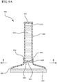
- a rupturable or breakable membrane 950 is interposed between the fluid reservoir 910 and the fluid dispensing chamber 930, thereby preventing the antiseptic agent 916 from flowing into the fluid dispensing chamber 930 prior to defeating the membrane 950.
- the device 900 is prepared by filling the reservoir 910 with a desired antiseptic agent 916. After filling the reservoir 910, the cap 920 is placed on the proximal end 912 of the reservoir 910 to seal the agent 916 within the reservoir 910. In some examples, the cap 920 is formed by heat pressing the proximal end 912 of the reservoir 910 thereby forming a seal.
- the membrane 950 is disk-shaped having a uniform depression or scoring 952 that is broken or defeated by applying lateral force to the membrane 950.
- the scoring 952 is broken by applying force to the applicator pad 940, whereby the force is transferred to the membrane 950 via the fluid dispensing chamber 930.
- the scoring 952 is broken by compressing or squeezing the fluid reservoir 910 to increase the pressure within the reservoir 910 beyond the strength of the scored surface 952.
- the antiseptic solution 916 within the reservoir 910 flows through the membrane 950 and is absorbed by the applicator pad 940.
- the thickness of the membrane 950 and the depth of the scoring may be varied dependent upon the calculated force desired to defeat the membrane 950.
- the illustrated membrane 950 is disk-shaped and configured to compatibly seat within the proximal end 932 of the fluid dispensing chamber 930.
- the scoring 952 comprises a webbed design featuring a plurality of scorings 960 having varying dimensions and breaking strengths.
- portions of the membrane 950 are scored at varying depths or graduated depths to provide various breaking strengths across the membrane 950.
- the membrane 950 breaks along some of the scored surface 952 and 960 to essentially form a gate valve. Since only some of the scored surfaces are defeated, the partially defeated membrane 950 controls flow of the antiseptic agent 916 through the membrane 950. However, upon apply additional lateral force to the reservoir 910, additional portions of the scored surfaces 952 and 960 are defeated thereby increasing the amount of antiseptic agent 916 permitted to flow through the membrane 950.
Description
- The present invention relates to systems and methods for providing an antiseptic applicator. An antiseptic applicator is used to apply an antiseptic agent to a desired surface thereby preparing the surface for an antiseptic procedure or treatment.
- Antiseptic and antibacterial agents are commonly used in the treatment of various injuries, such as cuts and abrasions. These agents are also commonly applied to various surfaces in preparation for sterile or antiseptic procedures. For example, a common pre-operative procedure in the medical industry involves rubbing alcohol, iodine or peroxide on a skin surface to kill bacteria and thus reduce the chance of infection. Other common practices include wiping down a chair or table surface with an antiseptic agent prior to exposing a patient or instruments to the surface.
- Typically, an applicator, such as a cotton swab or foam pad, is soaked with an antiseptic that must be poured from a bottle or other container. This step requires that the user remove the lid of the container and the foil seal to access the antiseptic. In an emergency situation, or in a situation where the one of the user's hands is occupied, the user is required to free both hands to access the antiseptic agent. Furthermore, once the bottle or other container is opened, the sterility of the bottle is compromised often resulting in excess waste of otherwise useful antiseptic agent.
- Following these steps, the antiseptic is commonly poured into an open, secondary container which provides a pool into which the applicator is dipped or soaked. The open, secondary container may include a dish or small bowl having a large opening through which the applicator is passed. In an emergency situation the user must take caution to prevent bumping or disturbing the secondary container so as to prevent a spill of the antiseptic. In the event that the antiseptic agent is spilled, additional antiseptic must be provided thereby requiring the user to once again access the container or bottle of antiseptic.
- In other procedures, an antiseptic agent is applied directly to a surface from the bottle or other container, and is then spread and applied with the applicator. During these procedures, the user must take precautions to control the amount of antiseptic used so as to contain the antiseptic and avoid wasting materials.
- For some procedures, a portion of the applicator that contacts the desired surface is held directly in the hand of the user. For example, where the applicator is a wipe and the surface is a table top, the user generally holds the wipe in their hand and rubs the surface with the wipe. The proximity of the user's hand to the table surface presents the danger of contaminating the newly sanitized surface with the user's hand. While the user may choose to wear protective gloves or wash their hands prior to applying the antiseptic, in an emergency situation the user may not have sufficient time to take the necessary precautions.
- Thus, while techniques currently exist that are used for applying an antiseptic agent to a desired surface, challenges still exist. Accordingly, it would be an improvement in the art to augment or even replace current techniques with other techniques.
-
US 2002/0076258 A1 describes a skin disinfectant applicator comprising a hollow shaft having a closed end and an open end. The open end is connected to a foam pad via a flow control valve for applying the disinfectant. -
US 2008/0219750 A1 describes a dual prep applicator for prepping surgery patients in an operating room. The apparatus comprises a shaft member holding an antiseptic solution. The antiseptic solution is applied to a patient via a sponge which is connected to the shaft member. - The present invention relates to a safe and convenient handheld applicator device for delivering an antiseptic solution to a desired surface. The applicator device includes a body having a lumen for receiving an antiseptic agent. The body is generally composed of a semi-flexible polymer material capable of being compressed or squeezed by a user. One end of the body is configured to receive a fluid reservoir containing a desired antiseptic solution. Upon coupling the fluid reservoir to the body, the solution within the reservoir is transferred to the lumen of the body. At the other end of the body, the device includes an adapter pad for absorbing and applying the antiseptic solution to a desired surface. The applicator pad generally includes a non-woven or foam pad material suitable for applying the antiseptic solution.
- A defeatable membrane is interposed between the lumen of the body and the applicator, such that the antiseptic agent is prevented from contacting the applicator. The device further includes a handle whereby upon activating the handle the membrane is defeated thereby permitting the antiseptic agent to flow through the membrane and contact the applicator. In examples, the membrane is defeated by simply compressing the body of the device to increase the pressure within the lumen. The increased pressure is released as the membrane is defeated and the antiseptic agent is permitted to flow through the membrane. In other examples, the membrane is replaced with a one-way valve that is defeated by increasing the pressure within the lumen of the body.
- In some embodiments of the present invention, the applicator is shaped and configured to apply the antiseptic agent to an orifice, such as a mouth or a respirator tube. In other embodiments, the applicator is shaped and configured to apply the antiseptic agent to a generally flat surface such as an I.V. insertion site, a surgical procedure site or a table.
- In some examples, the antiseptic applicator device includes a pair of opposing handles coupled to an applicator pad. Each handle includes an interior lumen configured to house a fluid reservoir, such as an ampoule or phial. Each lumen is in fluid communication with the applicator pad, such that as a fluid reservoir is defeated, the fluid contained within the reservoir is released and absorbed by the applicator pad.
- In some examples, the fluid reservoir of each handle is defeated by simply squeezing or compressing the outer surface of the handle to crush or break the reservoir material. In other examples, a wedge point is positioned between the opposing handles such that as the handles are moved to a closed position, the wedge point is driven into or against the fluid reservoirs thereby defeating the reservoirs.
- When a fluid reservoir is included in each of two handles, the fluid reservoir of each handle may include the same or different solutions. For example, where the antiseptic agent is a two-part reagent, the fluid reservoir of one handle may include the first part of the antiseptic agent, and the fluid reservoir of the other handle may include the second part of the antiseptic agent. Thus, when the reservoirs are defeated, the first and second halves of the antiseptic agent are mixed to provide the desired antiseptic solution.
- In some examples, it may be desirable to apply a first solution contained in the fluid reservoir of the first handle prior to applying a second solution contained in the fluid reservoir of the second handle. Thus, some examples of the device include a multistep wedge point whereby the first fluid reservoir is defeated based upon a first position of the opposing handles, and the second fluid reservoir is defeated based upon a second position of the opposing handles. Additionally, some examples include a layered applicator pad such that contaminated layers of the pad may be removed to provide a fresh, uncontaminated application surface.
- Finally, in some examples the device includes a membrane having a scored surface that partially defeated in response to lateral force. As the lateral force is increased, additional portions of the membrane are defeated thereby permitting increased flow of the antiseptic agent through the membrane. In other examples, the membrane includes a plurality of scorings having various thicknesses and dimensions to progressively defeat the membrane in response to progressive increases in lateral force against the membrane. In accordance with the present invention, there is provided an applicator device as defined in
claim 1. - Further advantages are achieved by the embodiments indicated by the dependent claims.
- In order that the manner in which the above-recited and other features and advantages of the invention are obtained will be readily understood, a more particular description of the invention briefly described above will be rendered by reference to specific embodiments thereof which are illustrated in the appended drawings. These drawings depict typical embodiments of the invention and are not therefore to be considered to limit the scope of the invention.
-
Figure 1 is a perspective view of an antiseptic applicator device in accordance with a representative embodiment of the present invention. -
Figure 2A is a cross-sectional view of an antiseptic applicator device prior to activation in accordance with a representative embodiment of the present invention. -
Figure 2B is a cross-sectional view of an antiseptic applicator device following activation in accordance with a representative embodiment of the present invention. -
Figure 3A is a cross-sectional view of an antiseptic applicator device prior to activation as coupled to a fluid reservoir in accordance with a representative embodiment of the present invention. -
Figure 3B is a cross-sectional view of an antiseptic applicator device prior to activation as coupled to a fluid reservoir in accordance with a representative embodiment of the present invention. -
Figure 4 is a cross-sectional view of an antiseptic applicator device including a one-way valve. -
Figure 5A is a perspective view of a two-handled antiseptic applicator device. -
Figure 5B is a top view of a two-handled antiseptic applicator device. -
Figure 5C is a cross-sectioned rear view of a two-handled antiseptic applicator device. -
Figure 5D is a cross-sectioned rear view of a two-handled antiseptic applicator device. -
Figure 6A is a top view of a two-handled antiseptic applicator device. -
Figure 6B is a top view of a two-handled antiseptic applicator device. -
Figure 7A is a top view of a two-handled antiseptic applicator device having a multistep wedge point. -
Figure 7B is a top view of a two-handled antiseptic applicator device having a multistep wedge point following breakage of the first phial. -
Figure 7C is a top view of a two-handled antiseptic applicator device having a multistep wedge point following breakage of the second phial. -
Figure 8 is a perspective view of a two-handled antiseptic applicator device having an elongated conjoined portion and angled handles. -
Figure 9A is a cross-sectioned view of an antiseptic applicator device incorporating a scored membrane. -
Figure 9B is a cross-section view ofFigure 9A demonstrating a scored membrane. - The presently preferred embodiments of the present invention will be best understood by reference to the drawings, wherein like reference numbers indicate identical or functionally similar elements. It will be readily understood that the components of the present invention, as generally described and illustrated in the figures herein, could be arranged and designed in a wide variety of different configurations. Thus, the following more detailed description, as represented in the figures, is not intended to limit the scope of the invention as claimed, but is merely representative of presently preferred embodiments of the invention.
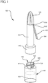
- Referring now to
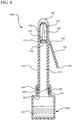
Figure 1 , an implementation of anantiseptic device 100 is shown. Theantiseptic device 100 generally includes abody 110, having aproximal end 112 and adistal end 114. Theproximal end 112 is generally configured to compatibly receive areservoir 120 or phial containing anantiseptic agent 122, shown in phantom. In some examples, thereservoir 120 contains approximately 0.5 - 50 mL of theantiseptic agent 122. In other examples, thereservoir 120 contains an alcohol-based antimicrobial solution. - For example, in some examples an antimicrobial solution includes a 50-95% alcohol solution which further includes additional antimicrobial agents such as CHG, PCMX, triclosan, octenidine, hexachlorophene, PVP-1, iodine, and/or quaterine compounds in the range of 0.05% to 5% w/w. The alcohol is generally selected from at least one of ethyl alcohol, isopropal alcohol, n-propanol alcohol, and mixtures thereof. In some examples, the solution further contains dimethicone, glycerin, cationic polymer such as PVP, cellulose, docosanol, BTMS, behenyl alcohol and/or poloxamer. In a preferred example, a base antimicrobial solution contains approximately 70% alcohol, 2% CHG and 28% USP purified water for skin prepping, and 0.12% CHG in alcohol for mouth disinfecting. One of skill in the art will appreciate that other ingredients, including those mentioned above, may be added to each of the base antimicrobial solutions to provide a desired antimicrobial or
antiseptic agent 122 for a specific application. - In some embodiments, the
reservoir 120 includes aneck portion 124 having a set ofthreads 126 for threadedly coupling to compatible threads 200 (not shown) located within theproximal end 112 of thebody 110. In other examples, thereservoir 120 is coupled to theproximal end 112 of thebody 110 via a pressure fit, a mechanical interface, or an adhesive. - The
reservoir 120 further includes amembrane 128 or seal to retain theagent 122 within thereservoir 120 prior to coupling thereservoir 120 to thebody 110. Themembrane 128 generally comprises a foil seal that is applied to theopening 130 via an adhesive or heat sealing process. In some examples, themembrane 128 comprises a plastic-coated paper or cardboard material that is applied to theopening 130 in a similar fashion. Themembrane 128 may also include a polymer material. Finally, in some examples, portions of the membrane are scored 132 or otherwise weakened thereby encouraging themembrane 128 to break or defeat in a predictable manner. - In some examples, the
proximal end 112 of thebody 110 further comprises a feature (not shown) whereby themembrane 128 is punctured or otherwise defeated upon coupling thereservoir 120 to thebody 110. For example, in some embodiments, theproximal end 112 includes a spike 202 (seeFigure 2A ), whereby upon threadedly coupling thereservoir 120 to theproximal end 112, thespike 202 punctures and displaces themembrane 128 to provide access to theantiseptic agent 122 within thereservoir 120. Alternatively, in other examples, themembrane 128 is physically removed from thereservoir 120 prior to coupling thereservoir 120 and thebody 110. - The
distal end 114 of thebody 110 includes anapplicator 140. Theapplicator 140 comprises a non-woven material or foam sponge pad that is attached to thedistal end 114 via an adhesive that is compatible with theantiseptic agent 122. The size and shape of theapplicator 140 varies dependent upon the intended application of theantiseptic device 100. For example, theapplicator 140 of theantiseptic device 100 is sized and shaped for use as either a mouth disinfectant device or a skin/surgical site disinfectant device. - Occasionally, the inner and/or outer surfaces of the mouth must be disinfected, for example, prior to the insertion of a respirator tube or other medical device into the mouth or throat. Accordingly, the shape and size of the
applicator 140 is designed to compatibly insert within the mouth of a patient. For example, anapplicator 140 for use as a mouth disinfectant device may include an elongated dome shape having a base diameter that is easily inserted into the patient's mouth. An elongated dome shape eliminates any right angles that may otherwise prevent thorough and even contact between theapplicator 140 and the natural, curved surfaces of the inner mouth. Additionally, in some embodiments, the outer surface of theapplicator 140 includes a small radius that permits application of the applicator to the inner and outer surfaces of a respirator tube or other medical device prior to inserting the device into the mouth of the patient. - Where the
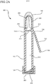
antiseptic device 100 is intended as a skin/surgical site disinfectant device, the shape and size of theapplicator 140 is selected to provide a broad, flat surface to maximize contact between theapplicator 140 and a generally flat skin surface. An example of such an applicator is shown and discussed in connection withFigure 3B , below. According to the invention, theantiseptic device 100 further comprises ahandle 150. Thehandle 150 comprises afirst end 152 coupled to thedistal end 114 of thebody 110 and asecond end 154 which extends outwardly from thebody 110. With reference toFigure 2A , a cross-section view of theantiseptic device 100 is shown. Thebody 110 of theantiseptic device 100 comprises a hollow interior orlumen 212 for receiving and storing theantiseptic agent 122 from thereservoir 120. Thebody 110 further includes afluid dispensing chamber 220. Thefluid dispensing chamber 220 is located at the mostdistal end 114 of thebody 110 and supports theapplicator 140. Thefluid dispensing chamber 220 comprises alumen 222 having a plurality ofwindows 224 through which theantiseptic agent 122 flows and is absorbed by theapplicator 140. In other examples thelumen 222 of thefluid dispensing chamber 220 comprises a plurality of holes, slits or other orifices. Abreakable membrane 270 is interposed between theinterior lumen 212 and thefluid dispensing chamber 220 of thebody 110. - The
membrane 270 is provided to prevent fluid communication between thelumen 212 and thefluid dispensing chamber 220. A portion of themembrane 270 is scored 272 or otherwise weakened to encourage themembrane 270 to break or defeat in a predictable manner. In some examples, themembrane 270 is located opposite thefirst end 152 of thehandle 150. Accordingly, as thehandle 150 is actuated towards thebody 110 from a closed position to an open position, thefirst end 152 of thehandle 150 applies a torque force to themembrane 270 thereby causing themembrane 270 to defeat along the scored 272 portion, as shown inFigure 2B . Once defeated, anopening 280 is provided through themembrane 270 such that thelumen 212 and thefluid dispensing chamber 220 are in fluid communication. - Referring now to
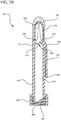
Figure 3A , a cross-section view of theantiseptic device 100 is shown coupled to a cross-sectioned reservoir, prior to actuating thehandle 150. As previously discussed, as theantiseptic device 100 is coupled to thereservoir 120 thespike feature 202 punctures themembrane 128 to provide fluid communication between thereservoir 120 and theinner lumen 212 of thebody 110. Thus, once themembrane 128 is defeated, theantiseptic device 100 and attachedreservoir 120 are inverted to permit theantiseptic agent 122 to flow into theinner lumen 212 of thebody 110. However, prior to actuating thehandle 150 to a closed position, theantiseptic agent 122 is substantially prevented from bypassing themembrane 272 and flowing into thefluid dispensing chamber 220. - Referring now to
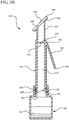
Figure 3B , a cross-section view of anantiseptic device 300 is shown coupled to a cross-sectioned reservoir, prior to actuating thehandle 150. In the process of coupling thedevice 300 to thereservoir 120, thespike feature 202 pierces, punctures or otherwise defeats themembrane 128 to provide fluid communication between thereservoir 120 and theinner lumen 212 of thedevice body 110. -
Antiseptic device 300 is modified to include a flat,linear applicator 340 having a broad surface for applying theantiseptic agent 122 to a generally flat surface. For this example, thefluid dispensing chamber 320 generally comprises a tubular shape having an angled,terminal end surface 322 configured to receive theflat applicator 340. Anopening 330 between thefluid dispensing chamber 320 and theapplicator 340 permits fluid within the dispensingchamber 320 to contact theapplicator 340 and to be absorbed thereby. -
Applicator 340 comprises a non-woven material or foam sponge pad that is sized and textured for applying theantiseptic agent 122 to a desired surface. For example, in some embodiments applicator 340 includes an abrasiveouter surface 342 to assist in exfoliation or debridement of a skin surface. In other examples,applicator 340 includes an abrasive outer surface to assist in scrubbing and disinfecting an object, such as a piece of machinery or a surface such as a table or bed surface. And in some examples,applicator 340 includes a smooth outer surface for applying theantiseptic agent 122 to disinfect a surface without harsh scrubbing. - In some examples, the
terminal end surface 322 is angled relative tobody portion 110 of theantiseptic device 300. Accordingly, when theapplicator 340 is coupled to theterminal end surface 322, theapplicator 340 is also angled relative to theapplicator body 110. The angle of theapplicator 340 is selected to assist a user in contacting a surface with theapplicator 340 while holding thebody portion 110 of the device in an ergonomically effective position. Furthermore, the position and length of thebody portion 110 is selected to provide a gripping surface to thedevice 300 and remove the user's hand from the area proximal to theapplicator 340. As such, the handle function of thebody portion 110 provides the user with control over thedevice 300 while preventing undesired exposure and/or contamination to the treatment site or surface. Referring now toFigure 4 , a cross-section view of anantiseptic device 400 is shown coupled to across-sectioned reservoir 120. In some examples, a one-way valve 410 is interposed between thefluid dispensing chamber 220 and theinner lumen 212 of thedevice 400. The one-way valve 410 generally comprises a flexible or semi-flexible polymer material that is secured within a constricted portion of theinner lumen 212. In some examples, thevalve 410 includes a duck bill or an umbrella valve. In other examples, thevalve 410 includes aslit 420 that is biased to a closed position so as to prevent fluid communication between thefluid dispensing chamber 220 and theinner lumen 212. However, when a pressure within theinner lumen 212 exceeds the threshold pressure of the one-way valve 140, the one-way valve 410 is defeated such that theslit 420 opens to provide fluid communication between theinner lumen 212 and thefluid dispensing chamber 220. - For example, in some examples, the
body portion 110 of thedevice 400 comprises a semi-flexible tubing material capable of being compressed or squeezed by the user. Thus, as the user compressed thebody portion 110, the pressure within theinner lumen 212 increases to exceed the threshold pressure of the one-way valve 140. When this occurs, the one-way valve 410 is defeated and theantiseptic agent 122 is permitted to bypass thevalve 410, via theslit 420, and flow into thefluid dispensing chamber 220. When the pressure subsides, the valve closes to prevent further flow into the dispensingchamber 220. In some examples, the one-way valve 410 is replaced with a mechanical valve that the user directly manipulates, such as a flapper or sliding valve. In other embodiments, the breakable membrane is replaced with a small hole that would allowantiseptic agent 122 to flow from theinner lumen 212 into the dispensingchamber 220 when thebody portion 110 is compressed. However, fluid would not be permitted to flow without compression due to the inner lumen being unvented and due to the surface tension of theantiseptic agent 122. - While applying positive pressure to the
body portion 110 of thedevice 400 is one method to defeat thevalve 410, one of skill in the art will appreciate that other methods may be used to equally defeat thevalve 410. For example, in some examples, thefluid dispensing chamber 220 is modified to include a vacuum source whereby the pressure within thefluid dispensing chamber 220 is decreased below the threshold pressure of the one-way valve 410. In other examples, thereservoir 120 comprises a syringe (not shown) containing anantiseptic agent 122. As the syringe is compressed, theantiseptic agent 122 is injected into theinner lumen 212 thereby increasing the pressure within theinner lumen 212. When the pressure within theinner lumen 212 exceeds the threshold pressure of the one-way valve 410, thevalve 410 is defeated and theantiseptic agent 122 flows into thefluid dispensing chamber 220 via the openedslit 420. - Referring now to
Figures 5A - 8 , various examples of a two-handled antiseptic device are shown. With reference toFigure 5A , a perspective view of a two-handleddevice 500 is shown. A two-handleddevice 500 generally comprises abifurcated body 510, wherein each half of the body forms an opposing handle. Aconjoined portion 520 of thebody 510 forms theterminal end 522 of thebody 510, and is coupled to a mountingplate 530. The mountingplate 530 provides a generally planar surface to which is attached anapplicator 540. - The
bifurcated body 510 includes afirst handle 512 and asecond handle 514. Thebifurcated body 510 further includes aninner lumen 516 which is comprised of interconnected lumens located within thefirst handle 512, thesecond handle 514 and theconjoined portion 520. In some examples, a portion of theinner lumen 516 is configured to receive an ampoule orphial 550 containing a desiredantiseptic agent 552. For example, in some examples, portions of thelumen 516 located in eachhandle phial 550 containing anantiseptic agent 552. - The
antiseptic agent 552 is released from eachphial 550 as thephial 550 is broken within the respective portion of thelumen 516. In some examples, thebifurcated body 510 comprises a semi-flexible polymer material that is capable of being compressed or flexed by the hand of the user. When the user compresses a single handle, forexample handle 512, thephial 550 contained within thehandle 512 is broken thereby releasing theantiseptic agent 552 from thephial 550 and into theinner lumen 516. Alternatively, when the user grasps and compresses both handles together, thephial 550 contained within eachhandle antiseptic agent 552 from eachphial 550 and into theinner lumen 516. Thus, the breakable material of thephial 550 serves as a barrier between theantiseptic agent 552 and theinner lumen 516. - Referring now to
Figure 5B , a top view of a two-handleddevice 500 is shown. In some examples, thebifurcated body 510 further includes awedge point 560 interposedly positioned between the opposinghandles wedge point 560 generally comprises a rigid feature having a tensile strength greater than the tensile strength of thephial 550 material. In some examples, thewedge point 560 is positioned between the opposing handles such that when thehandles wedge point 560 is pinched between the opposing handles resulting in thewedge point 560 breaking thephials 550. - With reference to
Figure 5C , a cross-section rear view of the two-handleddevice 500 is shown. In some examples, adjacent inner surfaces of the opposinghandles access windows 524 through which a middle portion of thewedge point 560 is positioned. Theaccess windows 524 are generally configured to provide passage for the middle portion of thewedge point 560 yet prevent passage of fluid located within the lumen of eachhandle wedge point 560 comprises afirst end 562 located within the inner lumen of thefirst handle 512, and asecond end 564 located within the inner lumen of thesecond handle 514. The first and second ends 562 and 564 are connected via the middle portion of thewedge point 560. In some examples, thefirst end 562 comprises a flat, anvil surface configured to directly abut thephial 550 within thefirst handle 512. Thesecond end 564 comprises a concaved surface configured to directly receive the outer diameter of thephial 550 located in thesecond handle 514. Thus, as the first and second handles are closed or brought together, thewedge point 560 binds eachphial 550 against the inner surface of each handle's outer wall. Continued closing of thehandles wedge point 560 through theirrespective phials 550 thereby releasing theantiseptic agents 552 contained therein. - Referring now to
Figure 5D , an alternate example ofwedge point 560 is shown. For this example, thefirst end 582 andsecond end 584 ofwedge point 580 are configured to couple to the external surfaces of opposinghandles wedge point 560 immobilizes the inner portions of the exterior surface thereby causing thephials 550 to be compressed and crushed between the interior surface of each handle's outer wall and the interior surface of each handle's inner wall. - Referring now to
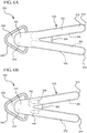
Figure 6A , an alternate example of the wedge point is shown. For this example,wedge point 570 is a molded, webbed extension linking the first andsecond handles conjoined portion 520 of thebody 510. In some examples,wedge point 570 is formed during the molding process of thedevice body 510, wherein a mold used to form thebody 510 includes a void to receive a sufficient amount of material to form thewedge point 570. In other examples,wedge point 570 is formed or molded in a separate process and subsequently coupled to the opposinghandles - In some examples, a
wedge point 580 is provided having wing features 582 for applying force to a specific portion of thephials 554. Somephials 554 include a scoredsurface 556 to encourage or control how thephial 554 is broken. Accordingly, in some examples, thewedge point 580 includeswinged features 582 that are designed to contact thephials 554 so as to break thephial 554 along the scoredsurface 556. The winged features 582 may include a molded feature of thedevice body 520, a separate device, or a combination of a molded feature and a separate device. - In some examples, each
phial 554 contained within the handle portion of theinner lumen 516 may contain the same or different solutions. Different solutions may be useful for procedures requiring a two-step preparation. For example, in some examples,phial 554 of thefirst handle 512 contains a detergent solution, whilephial 554 of thesecond handle 514 contains a disinfectant solution. A method for utilizing different solutions may include: 1) Breaking a first phial to release a first solution, wherein the first solution is a detergent to thoroughly wash and clean at and around an incision site to remove gross contamination before performing antiseptic skin preparation; and 2) Breaking a second phial to release a second solution, wherein the second solution is an appropriate antiseptic agent for skin preparation. - With reference to
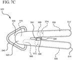
Figures 7A-7C , adevice 500 is shown housing afirst phial 556 containing a first solution, and asecond phial 558 containing a second solution.Device 500 further includes a multistep wedge point 590 interposedly positioned between thefirst handle 512 and thesecond handle 514. Finally,device 500 includes a layered applicator including afirst applicator 542 and asecond applicator 540. - The multistep wedge point 590 comprises a
first contact 592 coupled to asecond contact 594 via aspacer 596. Thefirst contact 592 is positioned adjacent to theconjoined portion 520 of the body so as to abut only thefirst phial 556. In some examples, the first andsecond phials handles distal end 566 of thefirst phial 556 overlaps thedistal end 568 of thesecond phial 558. Thespacer 596 length is selected to provide a distance between thefirst contact 592 and thesecond contact 594 such that thefirst contact 592 is positioned adjacent todistal end 566 of thefirst phial 556, and thesecond contact 594 is positioned adjacent todistal end 568 of thesecond phial 558. Thus, upon moving thehandles Figure 7B , thefirst contact 592 of the multistep wedge point 590 is driven into thedistal end 566 of thefirst phial 556. As thefirst phial 556 is pinched between thefirst contact 592 and the interior surface of thesecond handle 514, thephial 556 is defeated or broken 572 thereby releasing the first solution. - In some examples, the first solution comprises a detergent for removing gross contaminants from a desired surface. Accordingly, in some examples, the
device 500 includes afirst applicator 542 that is sized and textured for scrubbing or otherwise applying the detergent solution to the desired surface. Following complete application of the first solution, thefirst applicator 542 is removed from thedevice 500 to reveal the uncontaminatedsecond applicator 540. Thefirst applicator 542, including the gross contaminants contained thereon, is then discarded. - Following removal of the
first applicator 542, the opposinghandles Figure 7C . In this position, thesecond contact 594 of the multistep wedge point is driven into thedistal end 568 of thesecond phial 558. As thesecond phial 558 is pinched between thesecond contact 594 and the interior surface of thefirst handle 512, thephial 558 is defeated or broken 574 thereby releasing the second solution. - In some examples, the second solution comprises an antiseptic solution for cleaning or otherwise removing pathogens from a desired surface. Accordingly, in some examples, the
second applicator 540 is sized and textured for scrubbing or otherwise applying the antiseptic solution to the desired surface. Following complete application of the second solution, thedevice 500 is discarded. - Referring now to
Figure 8 , an alternate example of the two-handleddevice 800 is shown. In some examples, thebody 810 of the two-handleddevice 800 further includes an elongate conjoined portion 820, wherein thehandles inner lumen 816 thereby accommodating an increased volume ofantiseptic agent 852. Additionally, the increased volume permits placement of a sponge or filter 830 to prevent broken glass from entering theapplicator 540. - In some examples, the desired angle of the opposed handles 812 and 814 is selected to accommodate a user in optimally contacting a desired surface with the
applicator 540 while holding thehandles angled handles applicator 540. This increased spacing is beneficial to prevent undesirable contamination of theapplicator 540 and the treatment surface by the user's hands. Accordingly, in some examples, it is desirable to optimize the length of the conjoined portion 820 and the angle of thehandles device 800 that is effective for sanitizing a desired surface and provides an ergonomic grip. - In other examples, the size and length of the opposing
handles device 800 for a specific procedure or gripping technique. For example, for some procedures a large volume of antiseptic agent is needed thereby requiring that the size of the opposinghandles device 800 by pinching the device between their fingers, the size of the opposinghandles handles device 800 in their hand, the size of the opposinghandles - With reference to
Figure 9A , anapplicator device 900 is shown. Theapplicator device 900 comprises afluid reservoir 910 having aproximal end 912 and adistal end 914. Theproximal end 912 includes acap 920 that seals or otherwise closes theproximal end 912. Thedistal end 914 is coupled to afluid dispensing chamber 930 having afirst end 932 for receiving thedistal end 914 of thefluid dispensing chamber 930, and asecond end 934 for supporting anapplicator pad 940. A rupturable orbreakable membrane 950 is interposed between thefluid reservoir 910 and thefluid dispensing chamber 930, thereby preventing theantiseptic agent 916 from flowing into thefluid dispensing chamber 930 prior to defeating themembrane 950. - The
device 900 is prepared by filling thereservoir 910 with a desiredantiseptic agent 916. After filling thereservoir 910, thecap 920 is placed on theproximal end 912 of thereservoir 910 to seal theagent 916 within thereservoir 910. In some examples, thecap 920 is formed by heat pressing theproximal end 912 of thereservoir 910 thereby forming a seal. - In some examples, the
membrane 950 is disk-shaped having a uniform depression or scoring 952 that is broken or defeated by applying lateral force to themembrane 950. For example, in some examples, the scoring 952 is broken by applying force to theapplicator pad 940, whereby the force is transferred to themembrane 950 via thefluid dispensing chamber 930. In other examples, the scoring 952 is broken by compressing or squeezing thefluid reservoir 910 to increase the pressure within thereservoir 910 beyond the strength of the scoredsurface 952. Once defeated, theantiseptic solution 916 within thereservoir 910 flows through themembrane 950 and is absorbed by theapplicator pad 940. The thickness of themembrane 950 and the depth of the scoring may be varied dependent upon the calculated force desired to defeat themembrane 950. - Referring now to
Figure 9B , the illustratedmembrane 950 is disk-shaped and configured to compatibly seat within theproximal end 932 of thefluid dispensing chamber 930. In some examples, the scoring 952 comprises a webbed design featuring a plurality ofscorings 960 having varying dimensions and breaking strengths. For example, in some examples, portions of themembrane 950 are scored at varying depths or graduated depths to provide various breaking strengths across themembrane 950. Thus, when compressed with a lateral force along thereservoir 910, themembrane 950 breaks along some of the scoredsurface membrane 950 controls flow of theantiseptic agent 916 through themembrane 950. However, upon apply additional lateral force to thereservoir 910, additional portions of the scoredsurfaces antiseptic agent 916 permitted to flow through themembrane 950. - The present invention may be embodied in other specific forms without departing from its structures, methods, or other essential characteristics as broadly described herein and claimed hereinafter. The described embodiments are to be considered in all respects only as illustrative, and not restrictive. The scope of the invention is, therefore, indicated by the appended claims.
Claims (8)
- An applicator device comprising:a body (110) having a distal dispensing chamber (220) for receiving an antiseptic agent (122), the body comprising an interior lumen (212) comprising a proximal end (112), and a breakable membrane (270) interposed between the interior lumen and the distal dispensing chamber, the breakable membrane (270) having a scored portion (272), the body further comprising an outer surface adjacent the breakable membrane, the outer surface comprising a handle (150) extending outwardly therefrom, wherein the handle comprises a first end (152) coupled to the body (110) and a second end (154) that extends outwardly from the body (110), wherein in response to the handle (150) being actuated towards the body (110), the first end (152) of the handle applies a torque force to the breakable membrane (270) thereby causing the breakable membrane (270) to defeat along the scored portion (272), the proximal end further comprising a set of compatible threads (200), wherein the breakable membrane is defeated upon actuation of the handle, thereby providing fluid communication between the interior lumen and the distal dispensing chamber; anda pad coupled to an outer surface of the distal dispensing chamber and in fluid communication with the distal dispensing chamber via a plurality of windows (224).
- The device of claim 1, further comprising a reservoir (120) having a neck portion (124) comprising a set of threads (126) for threadedly coupling to the set of compatible threads (200).
- The device of claim 2, wherein the reservoir is configured to receiving the antiseptic agent.
- The device of claim 3, wherein the reservoir further comprises an opening (130) to which is applied a seal (128) to retain the antiseptic agent within the reservoir prior to coupling the reservoir to the body, wherein the proximal end (112) further comprises a spike feature (202), wherein in response to the applicator device_being coupled to the reservoir (120), the spike feature (202) punctures the seal (128) to provide fluid communication between the reservoir (120) and the inner lumen (212).
- The device of claim 3, wherein the distal dispensing chamber is devoid of the antiseptic agent prior to coupling the reservoir to the body.
- The device of claim 1, wherein the breakable membrane further comprises a score (272).
- The device of claim 1, wherein the breakable membrane prevents fluid communication between the interior lumen and the distal dispensing chamber prior to actuation of the handle.
- The device of claim 2, wherein the reservoir is a syringe.
Applications Claiming Priority (3)
| Application Number | Priority Date | Filing Date | Title |
|---|---|---|---|
| US24244509P | 2009-09-15 | 2009-09-15 | |
| US12/846,530 US8348913B2 (en) | 2009-09-15 | 2010-07-29 | Systems and methods for providing an antiseptic applicator |
| EP10742679.3A EP2477687B1 (en) | 2009-09-15 | 2010-08-04 | Systems and methods for providing an antiseptic applicator |
Related Parent Applications (1)
| Application Number | Title | Priority Date | Filing Date |
|---|---|---|---|
| EP10742679.3A Division EP2477687B1 (en) | 2009-09-15 | 2010-08-04 | Systems and methods for providing an antiseptic applicator |
Publications (2)
| Publication Number | Publication Date |
|---|---|
| EP3108922A1 EP3108922A1 (en) | 2016-12-28 |
| EP3108922B1 true EP3108922B1 (en) | 2018-06-13 |
Family
ID=43731273
Family Applications (2)
| Application Number | Title | Priority Date | Filing Date |
|---|---|---|---|
| EP10742679.3A Active EP2477687B1 (en) | 2009-09-15 | 2010-08-04 | Systems and methods for providing an antiseptic applicator |
| EP16178801.3A Active EP3108922B1 (en) | 2009-09-15 | 2010-08-04 | Systems for providing an antiseptic applicator |
Family Applications Before (1)
| Application Number | Title | Priority Date | Filing Date |
|---|---|---|---|
| EP10742679.3A Active EP2477687B1 (en) | 2009-09-15 | 2010-08-04 | Systems and methods for providing an antiseptic applicator |
Country Status (9)
| Country | Link |
|---|---|
| US (1) | US8348913B2 (en) |
| EP (2) | EP2477687B1 (en) |
| JP (1) | JP5632478B2 (en) |
| CN (1) | CN102497908B (en) |
| AU (1) | AU2010295916B2 (en) |
| BR (1) | BR112012005863B1 (en) |
| ES (2) | ES2687193T3 (en) |
| IN (1) | IN2012DN02023A (en) |
| WO (1) | WO2011034665A1 (en) |
Families Citing this family (35)
| Publication number | Priority date | Publication date | Assignee | Title |
|---|---|---|---|---|
| DE102007039177B4 (en) * | 2007-08-20 | 2013-05-23 | Sulzer Mixpac Ag | applicator |
| US9750893B1 (en) * | 2011-06-24 | 2017-09-05 | Michael S. Zelten | Syringe and swab system |
| FR2983411B1 (en) * | 2011-12-05 | 2014-03-14 | Pascal Ruard | BADIGEONNAGE TIP |
| US8801312B2 (en) * | 2011-12-16 | 2014-08-12 | Carefusion 2200, Inc. | Antiseptic applicator |
| US8899859B2 (en) | 2011-12-16 | 2014-12-02 | Carefusion 2200, Inc. | Antiseptic applicator |
| WO2013101890A1 (en) | 2011-12-29 | 2013-07-04 | 3M Innovative Properties Company | Cleaning system |
| US9265923B2 (en) * | 2012-04-27 | 2016-02-23 | Carefusion 2200, Inc. | Antiseptic applicator |
| US9205020B2 (en) * | 2012-04-27 | 2015-12-08 | Young Living Essential Oils, Lc | Massaging multiple roller-ball applicator for topical oils application |
| US9211228B2 (en) | 2012-04-27 | 2015-12-15 | Young Living Essential Oils, Lc | Massaging topical oils applicator |
| GB201209880D0 (en) * | 2012-05-31 | 2012-07-18 | Rieke Corp | Applicators |
| EP3040099A4 (en) * | 2013-08-29 | 2017-04-26 | Gold Crown Investment Limited | Multi-purpose healthcare device |
| WO2015032866A1 (en) * | 2013-09-06 | 2015-03-12 | Medaxis Ag | Handpiece for cleaning wounds |
| JP6273744B2 (en) * | 2013-09-30 | 2018-02-07 | 凸版印刷株式会社 | Two-component mixing container |
| US9757551B2 (en) | 2013-10-04 | 2017-09-12 | Carefusion 2200, Inc. | Antiseptic applicator |
| US9750922B2 (en) * | 2014-02-20 | 2017-09-05 | Becton, Dickinson And Company | Systems and methods for providing an antimicrobial dispensing applicator |
| US20160095477A1 (en) * | 2014-10-07 | 2016-04-07 | Christine Naughton | Skin-care device |
| US20160166816A1 (en) * | 2014-12-10 | 2016-06-16 | Carefusion 2200, Inc. | Antiseptic applicator |
| EP3147034A1 (en) * | 2015-09-25 | 2017-03-29 | Sulzer Mixpac AG | Applicator for ejecting doses of a flowable component |
| US10814114B2 (en) * | 2015-12-08 | 2020-10-27 | Dusa Pharmaceuticals, Inc. | Method and apparatus for applying a topical solution |
| DE102016100518B4 (en) * | 2016-01-13 | 2022-10-27 | Kulzer Gmbh | Breakaway micro-applicator for use with dental fluids |
| US11344220B2 (en) | 2016-05-13 | 2022-05-31 | Becton, Dickinson And Company | Invasive medical device cover with magnet |
| US10689152B2 (en) * | 2016-08-22 | 2020-06-23 | James Alexander Corporation | Dispenser and process |
| CA2977509C (en) * | 2016-08-30 | 2021-08-03 | Wal-Mart Stores, Inc. | Dry eraser and associated systems and methods |
| US10032552B2 (en) * | 2016-08-30 | 2018-07-24 | Becton, Dickinson And Company | Cover for tissue penetrating device with integrated magnets and magnetic shielding |
| CA2977506A1 (en) | 2016-08-30 | 2018-02-28 | Wal-Mart Stores, Inc. | Dry eraser and associated systems and methods |
| US10576256B2 (en) | 2016-12-13 | 2020-03-03 | Becton, Dickinson And Company | Antiseptic applicator |
| DE102017100443A1 (en) * | 2017-01-11 | 2018-07-12 | Madeleine Elixmann | Liquid plaster, applicator and their use |
| US11690434B2 (en) * | 2017-04-11 | 2023-07-04 | Ojip, Llc | Device for applying and removing nail polish |
| EP3482792B1 (en) * | 2017-11-10 | 2021-01-13 | Altera Tibbi Malzeme Sanayi Ve Ticaret Anonim Sirketi | A disinfectant applicator |
| DE102017129000B4 (en) * | 2017-12-06 | 2020-02-06 | Evolmed Gmbh | Dispenser head and associated handle for the administration of flowable substances to patients |
| KR101936892B1 (en) | 2018-11-20 | 2019-01-14 | 큐앤큐팜 주식회사 | Applicator for spreading disinfecting fluid on skin |
| CN113490473B (en) * | 2019-02-26 | 2023-04-14 | 3M创新有限公司 | System and method for preparing a liquid |
| WO2022103775A1 (en) | 2020-11-12 | 2022-05-19 | Singletto Inc. | Microbial disinfection for personal protection equipment |
| CN112981569B (en) * | 2021-02-03 | 2022-04-12 | 新疆金大禹环境科技有限公司 | Chemical fibre production and processing is with water conservancy diversion wrap-around oiling roller entirely |
| WO2023023041A1 (en) * | 2021-08-17 | 2023-02-23 | Becton, Dickinson And Company | Skin disinfectant wipe |
Family Cites Families (19)
| Publication number | Priority date | Publication date | Assignee | Title |
|---|---|---|---|---|
| CA1284784C (en) * | 1985-11-18 | 1991-06-11 | David F. Wirt | Liquid applicator |
| US4925327A (en) * | 1985-11-18 | 1990-05-15 | Minnesota Mining And Manufacturing Company | Liquid applicator with metering insert |
| US5147337A (en) * | 1990-05-07 | 1992-09-15 | Clifford Plone | Medicament dispenser |
| US5308180A (en) * | 1991-12-09 | 1994-05-03 | Minnesota Mining And Manufacturing Company | Liquid applicator with metering insert |
| US5288159A (en) * | 1992-12-04 | 1994-02-22 | Minnesota Mining And Manufacturing Company | Liquid applicator with frangible ampoule and support |
| US5509744A (en) * | 1995-06-23 | 1996-04-23 | Frazier; Thomas G. | Liquid applicator with slide ring activator |
| US5713843A (en) * | 1996-08-13 | 1998-02-03 | Allegiance Corporation | Sponge applicator with fluid ball |
| US6391014B1 (en) * | 1996-12-20 | 2002-05-21 | David G. Silverman | Strong diaphragm/safe needle/converting device combinations and their individual components |
| US6536975B1 (en) * | 2000-11-10 | 2003-03-25 | Mediflex Hospital Products, Inc. | Liquid applicator with opposed wings |
| US6371675B1 (en) * | 2000-12-20 | 2002-04-16 | Becton, Dickinson And Company | Skin disinfectant applicator |
| US20020076255A1 (en) * | 2000-12-20 | 2002-06-20 | Hoang Minh Q. | Skin disinfectant applicator |
| US20020076258A1 (en) * | 2000-12-20 | 2002-06-20 | Crosby Cynthia T. | Skin disinfectant applicator |
| TW544320B (en) * | 2002-02-08 | 2003-08-01 | Jung-Shin Lin | Medicine coating device with antibacterial dry intermediate section for coating and capable of instantaneously absorbing plural aseptic medical solutions |
| US6991394B2 (en) * | 2003-01-10 | 2006-01-31 | Medi-Flex, Inc. | Liquid applicator with a mechanism for fracturing multiple ampoules |
| US20040162533A1 (en) * | 2003-02-06 | 2004-08-19 | Alley Kenneth A. | Applicator device |
| US6729786B1 (en) * | 2003-03-14 | 2004-05-04 | Mediflex Hospital Products, Inc. | Liquid applicator for coloring a liquid |
| US6916133B2 (en) * | 2003-06-02 | 2005-07-12 | Becton, Dickinson And Company | Patient preparatory applicator with a back plug activator |
| US20080219750A1 (en) * | 2007-03-05 | 2008-09-11 | Marjorie Siegel | Dual prep applicator |
| CN101455876B (en) | 2007-12-12 | 2012-02-01 | 3M创新有限公司 | Painting device |
-
2010
- 2010-07-29 US US12/846,530 patent/US8348913B2/en active Active
- 2010-08-04 AU AU2010295916A patent/AU2010295916B2/en active Active
- 2010-08-04 IN IN2023DEN2012 patent/IN2012DN02023A/en unknown
- 2010-08-04 ES ES16178801.3T patent/ES2687193T3/en active Active
- 2010-08-04 EP EP10742679.3A patent/EP2477687B1/en active Active
- 2010-08-04 ES ES10742679.3T patent/ES2599070T3/en active Active
- 2010-08-04 EP EP16178801.3A patent/EP3108922B1/en active Active
- 2010-08-04 CN CN201080041120.6A patent/CN102497908B/en active Active
- 2010-08-04 BR BR112012005863A patent/BR112012005863B1/en active IP Right Grant
- 2010-08-04 WO PCT/US2010/044431 patent/WO2011034665A1/en active Application Filing
- 2010-08-04 JP JP2012529767A patent/JP5632478B2/en active Active
Non-Patent Citations (1)
| Title |
|---|
| None * |
Also Published As
| Publication number | Publication date |
|---|---|
| JP2013504404A (en) | 2013-02-07 |
| CN102497908B (en) | 2014-10-01 |
| EP2477687B1 (en) | 2016-07-20 |
| BR112012005863A2 (en) | 2016-02-16 |
| US8348913B2 (en) | 2013-01-08 |
| AU2010295916A1 (en) | 2012-03-22 |
| JP5632478B2 (en) | 2014-11-26 |
| EP2477687A1 (en) | 2012-07-25 |
| US20110066121A1 (en) | 2011-03-17 |
| WO2011034665A1 (en) | 2011-03-24 |
| ES2599070T3 (en) | 2017-01-31 |
| IN2012DN02023A (en) | 2015-08-21 |
| ES2687193T3 (en) | 2018-10-24 |
| BR112012005863B1 (en) | 2019-12-03 |
| AU2010295916B2 (en) | 2015-03-26 |
| CN102497908A (en) | 2012-06-13 |
| EP3108922A1 (en) | 2016-12-28 |
Similar Documents
| Publication | Publication Date | Title |
|---|---|---|
| EP3108922B1 (en) | Systems for providing an antiseptic applicator | |
| CA2938602C (en) | Systems and methods for providing an antimicrobial dispensing applicator | |
| AU2005334794B2 (en) | Medical skin applicator apparatus | |
| DK2379159T3 (en) | Device for applying fluid and procedure | |
| US20040162533A1 (en) | Applicator device | |
| US20150182738A1 (en) | Alcohol prep applicator | |
| WO2020039296A1 (en) | Flexible applicator handle region | |
| CN112638462B (en) | Applicator | |
| BR112016019240B1 (en) | APPLICATOR DEVICE AND METHOD TO MANUFACTURE AN APPLICATOR DEVICE |
Legal Events
| Date | Code | Title | Description |
|---|---|---|---|
| PUAI | Public reference made under article 153(3) epc to a published international application that has entered the european phase |
Free format text: ORIGINAL CODE: 0009012 |
|
| AC | Divisional application: reference to earlier application |
Ref document number: 2477687 Country of ref document: EP Kind code of ref document: P |
|
| AK | Designated contracting states |
Kind code of ref document: A1 Designated state(s): AL AT BE BG CH CY CZ DE DK EE ES FI FR GB GR HR HU IE IS IT LI LT LU LV MC MK MT NL NO PL PT RO SE SI SK SM TR |
|
| 17P | Request for examination filed |
Effective date: 20170627 |
|
| RBV | Designated contracting states (corrected) |
Designated state(s): AL AT BE BG CH CY CZ DE DK EE ES FI FR GB GR HR HU IE IS IT LI LT LU LV MC MK MT NL NO PL PT RO SE SI SK SM TR |
|
| GRAP | Despatch of communication of intention to grant a patent |
Free format text: ORIGINAL CODE: EPIDOSNIGR1 |
|
| INTG | Intention to grant announced |
Effective date: 20171222 |
|
| GRAS | Grant fee paid |
Free format text: ORIGINAL CODE: EPIDOSNIGR3 |
|
| GRAA | (expected) grant |
Free format text: ORIGINAL CODE: 0009210 |
|
| AC | Divisional application: reference to earlier application |
Ref document number: 2477687 Country of ref document: EP Kind code of ref document: P |
|
| AK | Designated contracting states |
Kind code of ref document: B1 Designated state(s): AL AT BE BG CH CY CZ DE DK EE ES FI FR GB GR HR HU IE IS IT LI LT LU LV MC MK MT NL NO PL PT RO SE SI SK SM TR |
|
| REG | Reference to a national code |
Ref country code: GB Ref legal event code: FG4D |
|
| REG | Reference to a national code |
Ref country code: CH Ref legal event code: EP Ref country code: AT Ref legal event code: REF Ref document number: 1007839 Country of ref document: AT Kind code of ref document: T Effective date: 20180615 |
|
| REG | Reference to a national code |
Ref country code: IE Ref legal event code: FG4D |
|
| REG | Reference to a national code |
Ref country code: DE Ref legal event code: R096 Ref document number: 602010051363 Country of ref document: DE |
|
| REG | Reference to a national code |
Ref country code: FR Ref legal event code: PLFP Year of fee payment: 9 |
|
| REG | Reference to a national code |
Ref country code: SE Ref legal event code: TRGR |
|
| REG | Reference to a national code |
Ref country code: NL Ref legal event code: MP Effective date: 20180613 |
|
| REG | Reference to a national code |
Ref country code: ES Ref legal event code: FG2A Ref document number: 2687193 Country of ref document: ES Kind code of ref document: T3 Effective date: 20181024 |
|
| REG | Reference to a national code |
Ref country code: LT Ref legal event code: MG4D |
|
| PG25 | Lapsed in a contracting state [announced via postgrant information from national office to epo] |
Ref country code: LT Free format text: LAPSE BECAUSE OF FAILURE TO SUBMIT A TRANSLATION OF THE DESCRIPTION OR TO PAY THE FEE WITHIN THE PRESCRIBED TIME-LIMIT Effective date: 20180613 Ref country code: FI Free format text: LAPSE BECAUSE OF FAILURE TO SUBMIT A TRANSLATION OF THE DESCRIPTION OR TO PAY THE FEE WITHIN THE PRESCRIBED TIME-LIMIT Effective date: 20180613 Ref country code: NO Free format text: LAPSE BECAUSE OF FAILURE TO SUBMIT A TRANSLATION OF THE DESCRIPTION OR TO PAY THE FEE WITHIN THE PRESCRIBED TIME-LIMIT Effective date: 20180913 Ref country code: BG Free format text: LAPSE BECAUSE OF FAILURE TO SUBMIT A TRANSLATION OF THE DESCRIPTION OR TO PAY THE FEE WITHIN THE PRESCRIBED TIME-LIMIT Effective date: 20180913 Ref country code: CY Free format text: LAPSE BECAUSE OF FAILURE TO SUBMIT A TRANSLATION OF THE DESCRIPTION OR TO PAY THE FEE WITHIN THE PRESCRIBED TIME-LIMIT Effective date: 20180613 |
|
| PG25 | Lapsed in a contracting state [announced via postgrant information from national office to epo] |
Ref country code: HR Free format text: LAPSE BECAUSE OF FAILURE TO SUBMIT A TRANSLATION OF THE DESCRIPTION OR TO PAY THE FEE WITHIN THE PRESCRIBED TIME-LIMIT Effective date: 20180613 Ref country code: GR Free format text: LAPSE BECAUSE OF FAILURE TO SUBMIT A TRANSLATION OF THE DESCRIPTION OR TO PAY THE FEE WITHIN THE PRESCRIBED TIME-LIMIT Effective date: 20180914 Ref country code: LV Free format text: LAPSE BECAUSE OF FAILURE TO SUBMIT A TRANSLATION OF THE DESCRIPTION OR TO PAY THE FEE WITHIN THE PRESCRIBED TIME-LIMIT Effective date: 20180613 |
|
| REG | Reference to a national code |
Ref country code: AT Ref legal event code: MK05 Ref document number: 1007839 Country of ref document: AT Kind code of ref document: T Effective date: 20180613 |
|
| PG25 | Lapsed in a contracting state [announced via postgrant information from national office to epo] |
Ref country code: NL Free format text: LAPSE BECAUSE OF FAILURE TO SUBMIT A TRANSLATION OF THE DESCRIPTION OR TO PAY THE FEE WITHIN THE PRESCRIBED TIME-LIMIT Effective date: 20180613 |
|
| PG25 | Lapsed in a contracting state [announced via postgrant information from national office to epo] |
Ref country code: AT Free format text: LAPSE BECAUSE OF FAILURE TO SUBMIT A TRANSLATION OF THE DESCRIPTION OR TO PAY THE FEE WITHIN THE PRESCRIBED TIME-LIMIT Effective date: 20180613 Ref country code: EE Free format text: LAPSE BECAUSE OF FAILURE TO SUBMIT A TRANSLATION OF THE DESCRIPTION OR TO PAY THE FEE WITHIN THE PRESCRIBED TIME-LIMIT Effective date: 20180613 Ref country code: IS Free format text: LAPSE BECAUSE OF FAILURE TO SUBMIT A TRANSLATION OF THE DESCRIPTION OR TO PAY THE FEE WITHIN THE PRESCRIBED TIME-LIMIT Effective date: 20181013 Ref country code: SK Free format text: LAPSE BECAUSE OF FAILURE TO SUBMIT A TRANSLATION OF THE DESCRIPTION OR TO PAY THE FEE WITHIN THE PRESCRIBED TIME-LIMIT Effective date: 20180613 Ref country code: CZ Free format text: LAPSE BECAUSE OF FAILURE TO SUBMIT A TRANSLATION OF THE DESCRIPTION OR TO PAY THE FEE WITHIN THE PRESCRIBED TIME-LIMIT Effective date: 20180613 Ref country code: RO Free format text: LAPSE BECAUSE OF FAILURE TO SUBMIT A TRANSLATION OF THE DESCRIPTION OR TO PAY THE FEE WITHIN THE PRESCRIBED TIME-LIMIT Effective date: 20180613 Ref country code: PL Free format text: LAPSE BECAUSE OF FAILURE TO SUBMIT A TRANSLATION OF THE DESCRIPTION OR TO PAY THE FEE WITHIN THE PRESCRIBED TIME-LIMIT Effective date: 20180613 |
|
| PG25 | Lapsed in a contracting state [announced via postgrant information from national office to epo] |
Ref country code: SM Free format text: LAPSE BECAUSE OF FAILURE TO SUBMIT A TRANSLATION OF THE DESCRIPTION OR TO PAY THE FEE WITHIN THE PRESCRIBED TIME-LIMIT Effective date: 20180613 |
|
| REG | Reference to a national code |
Ref country code: DE Ref legal event code: R097 Ref document number: 602010051363 Country of ref document: DE |
|
| PG25 | Lapsed in a contracting state [announced via postgrant information from national office to epo] |
Ref country code: MC Free format text: LAPSE BECAUSE OF FAILURE TO SUBMIT A TRANSLATION OF THE DESCRIPTION OR TO PAY THE FEE WITHIN THE PRESCRIBED TIME-LIMIT Effective date: 20180613 |
|
| REG | Reference to a national code |
Ref country code: CH Ref legal event code: PL |
|
| PLBE | No opposition filed within time limit |
Free format text: ORIGINAL CODE: 0009261 |
|
| STAA | Information on the status of an ep patent application or granted ep patent |
Free format text: STATUS: NO OPPOSITION FILED WITHIN TIME LIMIT |
|
| PG25 | Lapsed in a contracting state [announced via postgrant information from national office to epo] |
Ref country code: LI Free format text: LAPSE BECAUSE OF NON-PAYMENT OF DUE FEES Effective date: 20180831 Ref country code: CH Free format text: LAPSE BECAUSE OF NON-PAYMENT OF DUE FEES Effective date: 20180831 Ref country code: LU Free format text: LAPSE BECAUSE OF NON-PAYMENT OF DUE FEES Effective date: 20180804 |
|
| 26N | No opposition filed |
Effective date: 20190314 |
|
| PG25 | Lapsed in a contracting state [announced via postgrant information from national office to epo] |
Ref country code: SI Free format text: LAPSE BECAUSE OF FAILURE TO SUBMIT A TRANSLATION OF THE DESCRIPTION OR TO PAY THE FEE WITHIN THE PRESCRIBED TIME-LIMIT Effective date: 20180613 Ref country code: DK Free format text: LAPSE BECAUSE OF FAILURE TO SUBMIT A TRANSLATION OF THE DESCRIPTION OR TO PAY THE FEE WITHIN THE PRESCRIBED TIME-LIMIT Effective date: 20180613 |
|
| PG25 | Lapsed in a contracting state [announced via postgrant information from national office to epo] |
Ref country code: AL Free format text: LAPSE BECAUSE OF FAILURE TO SUBMIT A TRANSLATION OF THE DESCRIPTION OR TO PAY THE FEE WITHIN THE PRESCRIBED TIME-LIMIT Effective date: 20180613 |
|
| PG25 | Lapsed in a contracting state [announced via postgrant information from national office to epo] |
Ref country code: MT Free format text: LAPSE BECAUSE OF NON-PAYMENT OF DUE FEES Effective date: 20180804 |
|
| PG25 | Lapsed in a contracting state [announced via postgrant information from national office to epo] |
Ref country code: TR Free format text: LAPSE BECAUSE OF FAILURE TO SUBMIT A TRANSLATION OF THE DESCRIPTION OR TO PAY THE FEE WITHIN THE PRESCRIBED TIME-LIMIT Effective date: 20180613 |
|
| PG25 | Lapsed in a contracting state [announced via postgrant information from national office to epo] |
Ref country code: PT Free format text: LAPSE BECAUSE OF FAILURE TO SUBMIT A TRANSLATION OF THE DESCRIPTION OR TO PAY THE FEE WITHIN THE PRESCRIBED TIME-LIMIT Effective date: 20180613 |
|
| PG25 | Lapsed in a contracting state [announced via postgrant information from national office to epo] |
Ref country code: HU Free format text: LAPSE BECAUSE OF FAILURE TO SUBMIT A TRANSLATION OF THE DESCRIPTION OR TO PAY THE FEE WITHIN THE PRESCRIBED TIME-LIMIT; INVALID AB INITIO Effective date: 20100804 Ref country code: MK Free format text: LAPSE BECAUSE OF NON-PAYMENT OF DUE FEES Effective date: 20180613 |
|
| PGFP | Annual fee paid to national office [announced via postgrant information from national office to epo] |
Ref country code: IT Payment date: 20230720 Year of fee payment: 14 Ref country code: IE Payment date: 20230724 Year of fee payment: 14 Ref country code: GB Payment date: 20230720 Year of fee payment: 14 Ref country code: ES Payment date: 20230901 Year of fee payment: 14 |
|
| PGFP | Annual fee paid to national office [announced via postgrant information from national office to epo] |
Ref country code: SE Payment date: 20230720 Year of fee payment: 14 Ref country code: FR Payment date: 20230720 Year of fee payment: 14 Ref country code: DE Payment date: 20230720 Year of fee payment: 14 Ref country code: BE Payment date: 20230720 Year of fee payment: 14 |