EP3108729A1 - Double implement connection at the rear of a vehicle - Google Patents
Double implement connection at the rear of a vehicle Download PDFInfo
- Publication number
- EP3108729A1 EP3108729A1 EP16175722.4A EP16175722A EP3108729A1 EP 3108729 A1 EP3108729 A1 EP 3108729A1 EP 16175722 A EP16175722 A EP 16175722A EP 3108729 A1 EP3108729 A1 EP 3108729A1
- Authority
- EP
- European Patent Office
- Prior art keywords
- top link
- agricultural
- trailer coupling
- agricultural implement
- point hitch
- Prior art date
- Legal status (The legal status is an assumption and is not a legal conclusion. Google has not performed a legal analysis and makes no representation as to the accuracy of the status listed.)
- Granted
Links
Images




Classifications
-
- A—HUMAN NECESSITIES
- A01—AGRICULTURE; FORESTRY; ANIMAL HUSBANDRY; HUNTING; TRAPPING; FISHING
- A01B—SOIL WORKING IN AGRICULTURE OR FORESTRY; PARTS, DETAILS, OR ACCESSORIES OF AGRICULTURAL MACHINES OR IMPLEMENTS, IN GENERAL
- A01B59/00—Devices specially adapted for connection between animals or tractors and agricultural machines or implements
- A01B59/04—Devices specially adapted for connection between animals or tractors and agricultural machines or implements for machines pulled or pushed by a tractor
- A01B59/042—Devices specially adapted for connection between animals or tractors and agricultural machines or implements for machines pulled or pushed by a tractor having pulling means arranged on the rear part of the tractor
- A01B59/043—Devices specially adapted for connection between animals or tractors and agricultural machines or implements for machines pulled or pushed by a tractor having pulling means arranged on the rear part of the tractor supported at three points, e.g. by quick-release couplings
-
- B—PERFORMING OPERATIONS; TRANSPORTING
- B60—VEHICLES IN GENERAL
- B60D—VEHICLE CONNECTIONS
- B60D1/00—Traction couplings; Hitches; Draw-gear; Towing devices
- B60D1/14—Draw-gear or towing devices characterised by their type
- B60D1/141—Arrangements or frames adapted to allow the connection of trailers to tractor three-point hitches
-
- B—PERFORMING OPERATIONS; TRANSPORTING
- B60—VEHICLES IN GENERAL
- B60D—VEHICLE CONNECTIONS
- B60D1/00—Traction couplings; Hitches; Draw-gear; Towing devices
- B60D2001/001—Traction couplings; Hitches; Draw-gear; Towing devices specially adapted for use on vehicles other than cars
- B60D2001/008—Traction couplings; Hitches; Draw-gear; Towing devices specially adapted for use on vehicles other than cars specially adapted for implements, e.g. towed tools
Definitions
- the present invention relates to agricultural tractors, and, more particularly, to the attachment of agricultural implements thereto.
- Agricultural tractors are used to pull various agricultural implements that are necessary for tilling, seedbed preparation, planting, mowing, raking, harvesting, baling, spraying, and fertilizing. Often multiple such agricultural implements may be pulled by the agricultural tractor at one time, such as tillage implements and sprayers. Some such agricultural implements are adapted to be drawn in tandem, such that the rear agricultural implement attaches to the front agricultural implement. However, not all agricultural implements are advantageously adapted to be used to tow a further agricultural implement, either as a consequence of their function or by nature of their design.
- an agricultural implement may be adapted to be attached to the three point hitch of an agricultural tractor, so that it can be raised and lowered to engage the ground, and as a consequence of its function or design, lack a sturdy rear mounting surface suitable as a further hitch mounting point.
- a second agricultural implement designed to be pulled behind such an arrangement may have a gooseneck, or a long extension that reaches over the foremost agricultural implement to the rear of the agricultural tractor, where it may attach to a trailer coupling.
- Three point hitches are useful to both draw and lift an agricultural implement. However, by their nature, they interfere with the usefulness of a conventional trailer coupling, which is usually mounted between the lift arms of the three point hitch and beneath the top link. In order to use the conventional trailer coupling when no three point hitch mounted agricultural implement is in use, the top link is often clipped up against the back of the agricultural tractor and out of the way. When the three point hitch is in use, however, clipping the top link out of the way of the trailer coupling is not possible. In order to employ the arrangement of agricultural implements described above, wherein the first agricultural implement is attached to the three point hitch and the second agricultural implement is attached to the trailer coupling, the prior art has employed various methods to make the trailer coupling accessible.
- German disclosure document DE 10 2014 213 896 A1 Schoarmueller .
- the trailer coupling is simply moved above the top link.
- a substantial bracket provides both the trailer coupling mounting surface and a replacement top link attachment point, as the original top link attachment point is both obscured by the bracket and utilized for reinforcement using a short fixed link.
- this method has several significant drawbacks.
- the bracket is necessarily very large and cumbersome, which would require an operator to expend considerable effort installing and removing it, or to leave it in place.
- What is needed in the art is a way to allow the use of both the three point hitch and the trailer coupling of an agricultural tractor when using a first agricultural implement adapted to be used with the three point hitch but lacking its own rear hitch mounting point, and when using a second agricultural implement having a gooseneck that reaches over the first agricultural implement to attach to the trailer coupling of the agricultural tractor, without raising the trailer coupling to a point above the top link of the three point hitch.
- the present invention provides such a way to allow the use of both the three point hitch and the trailer coupling of an agricultural tractor when using a first agricultural implement adapted to be used with the three point hitch but lacking its own rear hitch mounting point, and when using a second agricultural implement having a gooseneck that reaches over the first agricultural implement to attach to the trailer coupling of the agricultural tractor, without raising the trailer coupling to a point above the top link of the three point hitch.
- the invention in one form is directed to an agricultural tractor having a chassis, a three point hitch for attaching a first agricultural implement, and a trailer coupling for attaching a second agricultural implement having a gooseneck.
- the three point hitch has two lift arms for raising and lowering the first agricultural implement, and a top link.
- the top link has an opening that accommodates the passage therethrough of the gooseneck of the second agricultural implement as it attaches to the trailer coupling.
- the invention in another form is directed to a method of attaching two agricultural implements to an agricultural tractor.
- the method includes providing an agricultural tractor having a three point hitch and a trailer coupling, attaching a first agricultural implement to the three point hitch, and attaching a second agricultural implement to the trailer coupling.
- the second agricultural implement has a gooseneck for reaching over the first agricultural implement to the trailer coupling.
- the method further includes providing the three point hitch with two lift arms for raising and lowering the first agricultural implement attached to the three point hitch, and providing the three point hitch with a top link having a top link opening for accommodating the passage therethrough of the gooseneck of the second agricultural implement.
- An advantage of the present invention is that it allows such use of both the three point hitch and of the trailer coupling without requiring the use of an additional large and cumbersome bracket that locates the trailer coupling above the top link of the three point hitch.
- Another advantage is that the present invention maintains the agricultural tractor's original three point hitch geometry.
- a further advantage of the present invention is that it does not result in the generation of additional forces and bending moments into the tractor chassis and bracket mounting points as a consequence of the relocation of the trailer coupling above the top link of the three point hitch.
- Another advantage of the present invention is that it allows the rearmost agricultural implement to be connected to the agricultural tractor at a lower point, thereby minimizing the potential for tractor instability.
- agricultural tractor and “agricultural implement” are used principally throughout this specification for convenience but it is to be understood that these terms are not intended to be limiting.
- agricultural tractor refers to any towing vehicle equipped with a three point hitch
- agricultural implement refers to any towed device.
- forward, rearward, “left” and “right”, when used in connection with the agricultural tractor and/or components thereof are usually determined with reference to the direction of forward operative travel of the agricultural tractor, but again, they should not be construed as limiting.
- the terms “longitudinal” and “transverse” are determined with reference to the fore-and-aft direction of the agricultural tractor and are equally not to be construed as limiting.
- FIG. 1 there is shown an agricultural tractor 10 of ordinary design, having front wheels 12, rear wheels 14, an engine 16, and a chassis 18.
- the agricultural tractor 10 provides tractive effort through the rear wheels 14 and possible through the front wheels 12 using power supplied by the engine.
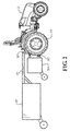
- Fig. 2 shows the agricultural tractor 10 of Fig. 1 , now with a first agricultural implement 30 connected to the agricultural tractor's three point hitch 50, which is largely obscured by the rear wheels 14 of the agricultural tractor 10.
- a second agricultural implement 32 has a gooseneck 34 which allows it to reach up and over the first agricultural implement 30 to connect to the agricultural tractor's trailer coupling 80, which is also largely obscured by the rear wheels 14 of the agricultural tractor 10.
- a rear view of the agricultural tractor 10 shows in greater detail a three point hitch 50 and trailer coupling 80 of ordinary design, being located generally between the rear wheels 14 of the agricultural tractor 10.
- the three point hitch 50 is provided with lift arms 56 and a top link 62.
- the lift arms 56 are raised and lowered by side links 54, one or both of which may be provided with a turnbuckle so that the side links 54 function to level an agricultural implement connected to the three point hitch 50.
- the side links 54 are connected to hydraulic arms 52 which are connected to a hydraulic system 68. In this way, the hydraulic system 68 causes the hydraulic arms 52 to rotate up and down, thereby raising and lowering the lift arms 56 through the side links 54.
- Stabilizer arms 60 prevent the lift arms 56 from swaying excessively from side to side, thereby stabilizing any agricultural implement attached thereto.
- Each of the lift arms 56 are provided with swivel ends 58, and the top link is provided with a swivel end 66, used to attach to an agricultural implement.
- the top link 62 itself is not usually powered to raise and lower, and merely acts as a parallel locating link. It is usually adjustable in length, so that the agricultural implement may be tilted forward or backward by extending it or retracting it, respectively.
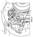
- an agricultural tractor 10 having a three point hitch 50 and a trailer coupling 80 arranged to enable a first agricultural implement to be attached to the three point hitch 50 and a second agricultural implement having a gooseneck 34 to be attached to the trailer coupling 80, without raising the trailer coupling 80 to a point above the top link 62 of the three point hitch 50.
- the three point hitch 50 is further provided with a top link 62 having an opening 64 therein.
- This opening 64 is located along the length of the top link 62 and is formed from the bifurcation of the link into two separate arms that are joined at both ends.
- the opening 64 is of sufficient breadth and length that it accommodates the relative motion of the top link 62 and of the gooseneck 34 as the three point hitch 50 articulates and as the gooseneck 34 moves.
- the top link 62 and its opening 64 may be of unitary construction, for example as a casting or forging, or it may be constructed, for example from joined or welded subcomponents.
- the top link 62 and its opening 64 may double as a turnbuckle, so that when not being used to allow the gooseneck 34 of a second agricultural implement to pass therethrough, the top link 62 may be rotated to retract or extend its length, providing tilting adjustment to a first agricultural implement attached to the three point hitch 50.
- the gooseneck 34 shown in Fig. 4 is shown in partial view, so that only the front most part is shown.
- the trailer coupling 80 is therefore mounted beneath the top link 62 having the top link opening 64.
- a trailer coupling vertical adjustment assembly 82 is shown raising the trailer coupling 80 to a closer proximity to the top link 62, of course without raising the trailer coupling 80 to above the top link 62.
- no such trailer coupling vertical adjustment assembly 82 may be required.
- the trailer coupling 80 may be a ball-type of trailer coupling, or may be of any other suitable type.
- Top link opening 64 is defined by a top link body 70, again being bifurcated along its length into two separate arms that are joined at both ends.
- the top link 62 is adjustable in length, so that two top link tube ends 72 having top link swivel ends 66 are provided.
- Threaded joints 74 connect the top link tube ends 72 to the top link body 70, which may be of opposing thread pitches, so that turning the top link body 70 causes the top link 62 to extend and retract like a turnbuckle.
- top link 62 may be a single piece casting or forging, or it may be constructed as a weldment or joining of separate castings, forgings, or otherwise formed subcomponents.
- the swivel ends 66 of the top link 62 may be free swiveling within their limits of travel, or alternately may be self-centering, so that the top link 62 remains largely level when in use, thereby minimizing contact between the top link 62 and the gooseneck 34 due to the top link 62 twisting along its axis.
- top link 62 again has a top link body 70, but rather than be bifurcated along its length into two separate arms that are joined at both ends, the top link body 70 has a single arm that forms a "C" arrangement around the area through which the goose neck 34 of the 2nd implement 32 will pass, which fulfills the same function as the top link opening 64 of Fig. 6 , and which can be optimized in shape and offset.
- top link 62 is adjustable in length, so that two top link tube ends 72 having top link swivel ends 66 are provided.
- Threaded joints 74 again connect the top link tube ends 72 to the top link body 70, which may be of opposing thread pitches, so that turning the top link body 70 causes the top link 62 to extend and retract like a turnbuckle.
- Alternate unitary methods may again be used to create the top link 62, so that it may be a single piece casting or forging, or it may be constructed as a weldment or joining of separate castings, forgings, or otherwise formed subcomponents.
- the swivel ends 66 of the top link 62 may again be free swiveling within their limits of travel, or alternately may be self-centering, so that the top link 62 remains largely level when in use, thereby minimizing contact between the top link 62 and the gooseneck 34 due to the top link 62 twisting along its axis. While this invention has been described with respect to at least one embodiment, the present invention can be further modified within the spirit and scope of this disclosure. This application is therefore intended to cover any variations, uses, or adaptations of the invention using its general principles. Further, this application is intended to cover such departures from the present disclosure as come within known or customary practice in the art to which this invention pertains and which fall within the limits of the appended claims.
Landscapes
- Life Sciences & Earth Sciences (AREA)
- Engineering & Computer Science (AREA)
- Mechanical Engineering (AREA)
- Zoology (AREA)
- Soil Sciences (AREA)
- Environmental Sciences (AREA)
- Transportation (AREA)
- Agricultural Machines (AREA)
Abstract
Description
- The present invention relates to agricultural tractors, and, more particularly, to the attachment of agricultural implements thereto.
- Agricultural tractors are used to pull various agricultural implements that are necessary for tilling, seedbed preparation, planting, mowing, raking, harvesting, baling, spraying, and fertilizing. Often multiple such agricultural implements may be pulled by the agricultural tractor at one time, such as tillage implements and sprayers. Some such agricultural implements are adapted to be drawn in tandem, such that the rear agricultural implement attaches to the front agricultural implement. However, not all agricultural implements are advantageously adapted to be used to tow a further agricultural implement, either as a consequence of their function or by nature of their design. For example, and not by way of limitation, an agricultural implement may be adapted to be attached to the three point hitch of an agricultural tractor, so that it can be raised and lowered to engage the ground, and as a consequence of its function or design, lack a sturdy rear mounting surface suitable as a further hitch mounting point. In this circumstance, a second agricultural implement designed to be pulled behind such an arrangement may have a gooseneck, or a long extension that reaches over the foremost agricultural implement to the rear of the agricultural tractor, where it may attach to a trailer coupling.
- Three point hitches are useful to both draw and lift an agricultural implement. However, by their nature, they interfere with the usefulness of a conventional trailer coupling, which is usually mounted between the lift arms of the three point hitch and beneath the top link. In order to use the conventional trailer coupling when no three point hitch mounted agricultural implement is in use, the top link is often clipped up against the back of the agricultural tractor and out of the way. When the three point hitch is in use, however, clipping the top link out of the way of the trailer coupling is not possible. In order to employ the arrangement of agricultural implements described above, wherein the first agricultural implement is attached to the three point hitch and the second agricultural implement is attached to the trailer coupling, the prior art has employed various methods to make the trailer coupling accessible.
- One possible method is shown in German
disclosure document DE 10 2014 213 896 A1 (Scharmueller ). In this method, the trailer coupling is simply moved above the top link. A substantial bracket provides both the trailer coupling mounting surface and a replacement top link attachment point, as the original top link attachment point is both obscured by the bracket and utilized for reinforcement using a short fixed link. However, this method has several significant drawbacks. First, the bracket is necessarily very large and cumbersome, which would require an operator to expend considerable effort installing and removing it, or to leave it in place. Second, it interferes with the agricultural tractor's original three point hitch geometry, as a consequence of the shorter top link. Third, the relocation of the trailer coupling to a point above the top link results in very high forces and bending moments being introduced into the tractor chassis and bracket mounting points. Fourth, and perhaps most significantly, relocation of the trailer coupling to a point above the top link results in the potential for tractor instability, which might result in tractor rollover or loss of ground contact at the front wheels. - What is needed in the art is a way to allow the use of both the three point hitch and the trailer coupling of an agricultural tractor when using a first agricultural implement adapted to be used with the three point hitch but lacking its own rear hitch mounting point, and when using a second agricultural implement having a gooseneck that reaches over the first agricultural implement to attach to the trailer coupling of the agricultural tractor, without raising the trailer coupling to a point above the top link of the three point hitch.
- The present invention provides such a way to allow the use of both the three point hitch and the trailer coupling of an agricultural tractor when using a first agricultural implement adapted to be used with the three point hitch but lacking its own rear hitch mounting point, and when using a second agricultural implement having a gooseneck that reaches over the first agricultural implement to attach to the trailer coupling of the agricultural tractor, without raising the trailer coupling to a point above the top link of the three point hitch.
- The invention in one form is directed to an agricultural tractor having a chassis, a three point hitch for attaching a first agricultural implement, and a trailer coupling for attaching a second agricultural implement having a gooseneck. The three point hitch has two lift arms for raising and lowering the first agricultural implement, and a top link. The top link has an opening that accommodates the passage therethrough of the gooseneck of the second agricultural implement as it attaches to the trailer coupling.
- The invention in another form is directed to a method of attaching two agricultural implements to an agricultural tractor. The method includes providing an agricultural tractor having a three point hitch and a trailer coupling, attaching a first agricultural implement to the three point hitch, and attaching a second agricultural implement to the trailer coupling. The second agricultural implement has a gooseneck for reaching over the first agricultural implement to the trailer coupling. The method further includes providing the three point hitch with two lift arms for raising and lowering the first agricultural implement attached to the three point hitch, and providing the three point hitch with a top link having a top link opening for accommodating the passage therethrough of the gooseneck of the second agricultural implement.
- An advantage of the present invention is that it allows such use of both the three point hitch and of the trailer coupling without requiring the use of an additional large and cumbersome bracket that locates the trailer coupling above the top link of the three point hitch.
- Another advantage is that the present invention maintains the agricultural tractor's original three point hitch geometry.
- A further advantage of the present invention is that it does not result in the generation of additional forces and bending moments into the tractor chassis and bracket mounting points as a consequence of the relocation of the trailer coupling above the top link of the three point hitch.
- Another advantage of the present invention is that it allows the rearmost agricultural implement to be connected to the agricultural tractor at a lower point, thereby minimizing the potential for tractor instability.
- The above-mentioned and other features and advantages of this invention, and the manner of attaining them, will become more apparent and the invention will be better understood by reference to the following description of an embodiment of the invention taken in conjunction with the accompanying drawings, wherein:
-
Fig. 1 is a side view of an agricultural tractor; -
Fig. 2 is a side view of an agricultural tractor with a first agricultural implement attached to its three point hitch and a second agricultural implement with a gooseneck attached to its trailer coupling; -
Fig. 3 is a rear view of an agricultural tractor showing a three point hitch and a conventional trailer coupling; -
Fig. 4 is a rear isometric view of a three point hitch and trailer coupling according to one embodiment of the invention; -
Fig. 5 is a top view of a three point hitch and trailer coupling according to one embodiment of the invention; -
Fig. 6 is a top view of a top link according to one embodiment of the invention; and -
Fig. 7 is a top view of an alternate embodiment of the inventive top link. - Corresponding reference characters indicate corresponding parts throughout the several views. The exemplification set out herein illustrates one embodiment of the invention and such exemplification is not to be construed as limiting the scope of the invention in any manner.
- The terms "agricultural tractor" and "agricultural implement" are used principally throughout this specification for convenience but it is to be understood that these terms are not intended to be limiting. Thus "agricultural tractor" refers to any towing vehicle equipped with a three point hitch, and "agricultural implement" refers to any towed device. Also the terms "forward", "rearward", "left" and "right", when used in connection with the agricultural tractor and/or components thereof are usually determined with reference to the direction of forward operative travel of the agricultural tractor, but again, they should not be construed as limiting. The terms "longitudinal" and "transverse" are determined with reference to the fore-and-aft direction of the agricultural tractor and are equally not to be construed as limiting.
- Referring now to the drawings, and more particularly to
Fig. 1 , there is shown anagricultural tractor 10 of ordinary design, havingfront wheels 12,rear wheels 14, anengine 16, and achassis 18. Theagricultural tractor 10 provides tractive effort through therear wheels 14 and possible through thefront wheels 12 using power supplied by the engine.Fig. 2 shows theagricultural tractor 10 ofFig. 1 , now with a firstagricultural implement 30 connected to the agricultural tractor's threepoint hitch 50, which is largely obscured by therear wheels 14 of theagricultural tractor 10. A secondagricultural implement 32 has agooseneck 34 which allows it to reach up and over the firstagricultural implement 30 to connect to the agricultural tractor'strailer coupling 80, which is also largely obscured by therear wheels 14 of theagricultural tractor 10. - Referring now to
Fig. 3 , a rear view of theagricultural tractor 10 shows in greater detail a threepoint hitch 50 andtrailer coupling 80 of ordinary design, being located generally between therear wheels 14 of theagricultural tractor 10. The threepoint hitch 50 is provided withlift arms 56 and atop link 62. Thelift arms 56 are raised and lowered byside links 54, one or both of which may be provided with a turnbuckle so that theside links 54 function to level an agricultural implement connected to the threepoint hitch 50. Theside links 54 are connected tohydraulic arms 52 which are connected to ahydraulic system 68. In this way, thehydraulic system 68 causes thehydraulic arms 52 to rotate up and down, thereby raising and lowering thelift arms 56 through theside links 54. Stabilizerarms 60, or alternately check chains, prevent thelift arms 56 from swaying excessively from side to side, thereby stabilizing any agricultural implement attached thereto. Each of thelift arms 56 are provided withswivel ends 58, and the top link is provided with aswivel end 66, used to attach to an agricultural implement. Thetop link 62 itself is not usually powered to raise and lower, and merely acts as a parallel locating link. It is usually adjustable in length, so that the agricultural implement may be tilted forward or backward by extending it or retracting it, respectively. - Referring now to
Figs. 4 and5 , an embodiment of the present invention is shown, anagricultural tractor 10 having a threepoint hitch 50 and atrailer coupling 80 arranged to enable a first agricultural implement to be attached to the threepoint hitch 50 and a second agricultural implement having agooseneck 34 to be attached to thetrailer coupling 80, without raising thetrailer coupling 80 to a point above thetop link 62 of the threepoint hitch 50. Specifically, in addition to thehydraulic arms 52, the side links 54, and thelift arms 56 located generally between therear wheels 14 of theagricultural tractor 10, the threepoint hitch 50 is further provided with atop link 62 having anopening 64 therein. Thisopening 64 is located along the length of thetop link 62 and is formed from the bifurcation of the link into two separate arms that are joined at both ends. Theopening 64 is of sufficient breadth and length that it accommodates the relative motion of thetop link 62 and of thegooseneck 34 as the threepoint hitch 50 articulates and as thegooseneck 34 moves. - The
top link 62 and itsopening 64 may be of unitary construction, for example as a casting or forging, or it may be constructed, for example from joined or welded subcomponents. As a further example, thetop link 62 and itsopening 64 may double as a turnbuckle, so that when not being used to allow thegooseneck 34 of a second agricultural implement to pass therethrough, thetop link 62 may be rotated to retract or extend its length, providing tilting adjustment to a first agricultural implement attached to the threepoint hitch 50. Note that thegooseneck 34 shown inFig. 4 is shown in partial view, so that only the front most part is shown. - The
trailer coupling 80 is therefore mounted beneath thetop link 62 having thetop link opening 64. In the embodiment shown, a trailer couplingvertical adjustment assembly 82 is shown raising thetrailer coupling 80 to a closer proximity to thetop link 62, of course without raising thetrailer coupling 80 to above thetop link 62. Depending upon the design and amount of relative articulation of the two agricultural implements attached to the threepoint hitch 50 and to thetrailer coupling 80, and upon the size of the top link opening 64, no such trailer couplingvertical adjustment assembly 82 may be required. Thetrailer coupling 80 may be a ball-type of trailer coupling, or may be of any other suitable type. - Referring now to
Fig. 6 , a detail view of thetop link 62 is shown.Top link opening 64 is defined by atop link body 70, again being bifurcated along its length into two separate arms that are joined at both ends. In this embodiment, thetop link 62 is adjustable in length, so that two top link tube ends 72 having top link swivel ends 66 are provided. Threaded joints 74 connect the top link tube ends 72 to thetop link body 70, which may be of opposing thread pitches, so that turning thetop link body 70 causes thetop link 62 to extend and retract like a turnbuckle. Alternate unitary methods may be used to create thetop link 62, so that it may be a single piece casting or forging, or it may be constructed as a weldment or joining of separate castings, forgings, or otherwise formed subcomponents. The swivel ends 66 of thetop link 62 may be free swiveling within their limits of travel, or alternately may be self-centering, so that thetop link 62 remains largely level when in use, thereby minimizing contact between thetop link 62 and thegooseneck 34 due to thetop link 62 twisting along its axis. - Referring now to
Fig. 7 , an additional embodiment of thetop link 62 is shown. Thetop link 62 again has atop link body 70, but rather than be bifurcated along its length into two separate arms that are joined at both ends, thetop link body 70 has a single arm that forms a "C" arrangement around the area through which thegoose neck 34 of the 2nd implement 32 will pass, which fulfills the same function as the top link opening 64 ofFig. 6 , and which can be optimized in shape and offset. Again,top link 62 is adjustable in length, so that two top link tube ends 72 having top link swivel ends 66 are provided. Threaded joints 74 again connect the top link tube ends 72 to thetop link body 70, which may be of opposing thread pitches, so that turning thetop link body 70 causes thetop link 62 to extend and retract like a turnbuckle. Alternate unitary methods may again be used to create thetop link 62, so that it may be a single piece casting or forging, or it may be constructed as a weldment or joining of separate castings, forgings, or otherwise formed subcomponents. The swivel ends 66 of thetop link 62 may again be free swiveling within their limits of travel, or alternately may be self-centering, so that thetop link 62 remains largely level when in use, thereby minimizing contact between thetop link 62 and thegooseneck 34 due to thetop link 62 twisting along its axis.
While this invention has been described with respect to at least one embodiment, the present invention can be further modified within the spirit and scope of this disclosure. This application is therefore intended to cover any variations, uses, or adaptations of the invention using its general principles. Further, this application is intended to cover such departures from the present disclosure as come within known or customary practice in the art to which this invention pertains and which fall within the limits of the appended claims.
Claims (15)
- An agricultural tractor (10), comprising:a chassis (12);a three point hitch (50) for attaching a first agricultural implement (30); anda trailer coupling (80) for attaching a second agricultural implement (32) having a gooseneck (34);characterized in that the three point hitch (50) comprises:two lift arms (56) for raising and lowering the first agricultural implement (30) attached to the three point hitch (50); anda top link (62) having a top link opening (64) for accommodating the passage therethrough of the gooseneck (34) of the second agricultural implement (32), the gooseneck (34) of the second agricultural implement (32) being attached to the trailer coupling (80).
- The agricultural tractor (10) of claim 1, wherein:the top link (62) is one of a casting, a forging, and a weldment.
- The agricultural tractor (10) of claim 1, wherein:the top link (62) is one of bifurcated along its length into two separate arms joined at their ends and formed with a single arm in a "C" arrangement.
- The agricultural tractor (10) of claim 1, wherein:the top link (62) is adjustable in length, having a top link body (70) with the top link opening (64), and having two top link tube ends (72), the top link body (70) and the top link tube ends (72) being connected using threads so configured that turning the top link body (70) extends or retracts the length of the top link (62).
- The agricultural tractor (10) of claims 1 - 4, wherein:the top link (62) further having swivel ends (66).
- The agricultural tractor (10) of claim 5, wherein:the swivel ends (66) of the top link (62) are self-centering, in order to minimize contact between the top link (62) and the gooseneck (34) of the second agricultural implement (32).
- The agricultural tractor (10) of claims 1 - 6, wherein:the trailer coupling (80) is a ball-type trailer coupling.
- The agricultural tractor (10) of claims 1 - 7, further comprising:a trailer coupling vertical adjustment assembly (82) located between the two lift arms (56) and beneath the top link (62).
- A method of attaching two agricultural implements (30, 32) to an agricultural tractor (10), comprising the steps of:providing an agricultural tractor (10) having a three point hitch (50) and a trailer coupling (80);attaching a first agricultural implement (30) to the three point hitch (50); andattaching a second agricultural implement (32) to the trailer coupling (80), the second agricultural implement (32) having a gooseneck (34) for reaching over the first agricultural implement (30) to the trailer coupling (80);characterized in that the method further comprises the steps of:providing the three point hitch (50) with two lift arms (56) for raising and lowering the first agricultural implement (30) attached to the three point hitch (50); andproviding the three point hitch (50) with a top link (62) having a top link opening (64) for accommodating the passage therethrough of the gooseneck (34) of the second agricultural implement (32).
- The method of claim 9, wherein:the top link (62) is one of a casting, a forging, and a weldment.
- The method of claim 9, wherein:the top link (62) is adjustable in length, having a top link body (70) with the top link opening (64), and having two top link tube ends (72), the top link body (70) and the top link tube ends (72) being connected using threads so configured that turning the top link body (70) extends or retracts the length of the top link (62).
- The method of claims 9 - 11, wherein:the top link (62) further having swivel ends (66).
- The method of claim 12, wherein:the swivel ends (66) of the top link (62) are self-centering, in order to minimize contact between the top link (62) and the gooseneck (34) of the second agricultural implement (32).
- The method of claims 9 - 13, wherein:the trailer coupling (80) is a ball-type trailer coupling.
- The method of claims 9 - 14, further comprising:providing a trailer coupling vertical adjustment assembly (82) located between the two lift arms (56) and beneath the top link (62).
Applications Claiming Priority (1)
| Application Number | Priority Date | Filing Date | Title |
|---|---|---|---|
| ITUB20151630 | 2015-06-25 |
Publications (2)
| Publication Number | Publication Date |
|---|---|
| EP3108729A1 true EP3108729A1 (en) | 2016-12-28 |
| EP3108729B1 EP3108729B1 (en) | 2019-05-01 |
Family
ID=53901053
Family Applications (1)
| Application Number | Title | Priority Date | Filing Date |
|---|---|---|---|
| EP16175722.4A Active EP3108729B1 (en) | 2015-06-25 | 2016-06-22 | Double implement connection at the rear of a vehicle |
Country Status (1)
| Country | Link |
|---|---|
| EP (1) | EP3108729B1 (en) |
Cited By (1)
| Publication number | Priority date | Publication date | Assignee | Title |
|---|---|---|---|---|
| WO2023006659A1 (en) * | 2021-07-30 | 2023-02-02 | ERO GmbH | Tractor-trailer assembly |
Citations (3)
| Publication number | Priority date | Publication date | Assignee | Title |
|---|---|---|---|---|
| FR2034251A1 (en) * | 1969-03-03 | 1970-12-11 | Huard Ucf | |
| WO2010117290A2 (en) * | 2009-04-10 | 2010-10-14 | Stanko Mandic | Combined cultivating machine for tilling with a rotary plough, soil fertilizing, preparing, stabilizing and sowing of crops |
| DE102014213896A1 (en) | 2013-07-18 | 2015-01-22 | Josef Scharmueller | coupling support |
-
2016
- 2016-06-22 EP EP16175722.4A patent/EP3108729B1/en active Active
Patent Citations (3)
| Publication number | Priority date | Publication date | Assignee | Title |
|---|---|---|---|---|
| FR2034251A1 (en) * | 1969-03-03 | 1970-12-11 | Huard Ucf | |
| WO2010117290A2 (en) * | 2009-04-10 | 2010-10-14 | Stanko Mandic | Combined cultivating machine for tilling with a rotary plough, soil fertilizing, preparing, stabilizing and sowing of crops |
| DE102014213896A1 (en) | 2013-07-18 | 2015-01-22 | Josef Scharmueller | coupling support |
Cited By (1)
| Publication number | Priority date | Publication date | Assignee | Title |
|---|---|---|---|---|
| WO2023006659A1 (en) * | 2021-07-30 | 2023-02-02 | ERO GmbH | Tractor-trailer assembly |
Also Published As
| Publication number | Publication date |
|---|---|
| EP3108729B1 (en) | 2019-05-01 |
Similar Documents
| Publication | Publication Date | Title |
|---|---|---|
| US9873300B1 (en) | Trailer hitch apparatus with lateral shift capability | |
| US6769496B2 (en) | Strut for a hitch device for attaching farm implements to a tractor | |
| US9491898B2 (en) | Length adjustable lifting strut | |
| US8925964B1 (en) | Ballast assembly | |
| US8096571B1 (en) | Tractor hitch assembly and trailer with hydraulic pump | |
| US10569803B2 (en) | Tow behind steerable caddy trailer | |
| ATE540570T1 (en) | CONNECTION BETWEEN TRACTOR AND TOWING ARM OF A TOWED HARVESTING MACHINE | |
| CA1154293A (en) | Dual implement hitch | |
| US3112124A (en) | Double implement drawbar | |
| US9955621B2 (en) | Front fold implement frame with pivotal draft link connection | |
| US20130264079A1 (en) | Quick-attach assembly for attaching an implement to an off-road vehicle | |
| EP3108729B1 (en) | Double implement connection at the rear of a vehicle | |
| CA2809455C (en) | Agricultural caddy and trailer assembly | |
| US7055618B2 (en) | Hydraulic pump drive | |
| US7478823B2 (en) | Drawbar clevis assembly | |
| US2971774A (en) | Double implement drawbar | |
| US11483956B2 (en) | Agricultural tractor with combined support for hitch and anti-roll systems | |
| US3469636A (en) | Plow assembly | |
| US10343469B2 (en) | Hitch hook with sliding latch | |
| US9795072B2 (en) | Biasing apparatus for floating hitch implements | |
| US2726589A (en) | Hitch stabilizer | |
| ZA202304385B (en) | Towing arrangement for a towing vehicle, system, trailer, and method | |
| US4552224A (en) | Hitch assembly for a tandem disc implement | |
| DE102012015556B4 (en) | Semi-trailer with a dump body | |
| US7547033B1 (en) | Convertible hitch |
Legal Events
| Date | Code | Title | Description |
|---|---|---|---|
| PUAI | Public reference made under article 153(3) epc to a published international application that has entered the european phase |
Free format text: ORIGINAL CODE: 0009012 |
|
| STAA | Information on the status of an ep patent application or granted ep patent |
Free format text: STATUS: THE APPLICATION HAS BEEN PUBLISHED |
|
| AK | Designated contracting states |
Kind code of ref document: A1 Designated state(s): AL AT BE BG CH CY CZ DE DK EE ES FI FR GB GR HR HU IE IS IT LI LT LU LV MC MK MT NL NO PL PT RO RS SE SI SK SM TR |
|
| AX | Request for extension of the european patent |
Extension state: BA ME |
|
| STAA | Information on the status of an ep patent application or granted ep patent |
Free format text: STATUS: REQUEST FOR EXAMINATION WAS MADE |
|
| 17P | Request for examination filed |
Effective date: 20170628 |
|
| RBV | Designated contracting states (corrected) |
Designated state(s): AL AT BE BG CH CY CZ DE DK EE ES FI FR GB GR HR HU IE IS IT LI LT LU LV MC MK MT NL NO PL PT RO RS SE SI SK SM TR |
|
| RIC1 | Information provided on ipc code assigned before grant |
Ipc: B60D 1/00 20060101ALI20181009BHEP Ipc: B60D 1/14 20060101ALI20181009BHEP Ipc: A01B 59/043 20060101AFI20181009BHEP |
|
| GRAP | Despatch of communication of intention to grant a patent |
Free format text: ORIGINAL CODE: EPIDOSNIGR1 |
|
| STAA | Information on the status of an ep patent application or granted ep patent |
Free format text: STATUS: GRANT OF PATENT IS INTENDED |
|
| INTG | Intention to grant announced |
Effective date: 20181130 |
|
| GRAS | Grant fee paid |
Free format text: ORIGINAL CODE: EPIDOSNIGR3 |
|
| GRAA | (expected) grant |
Free format text: ORIGINAL CODE: 0009210 |
|
| STAA | Information on the status of an ep patent application or granted ep patent |
Free format text: STATUS: THE PATENT HAS BEEN GRANTED |
|
| AK | Designated contracting states |
Kind code of ref document: B1 Designated state(s): AL AT BE BG CH CY CZ DE DK EE ES FI FR GB GR HR HU IE IS IT LI LT LU LV MC MK MT NL NO PL PT RO RS SE SI SK SM TR |
|
| REG | Reference to a national code |
Ref country code: GB Ref legal event code: FG4D |
|
| REG | Reference to a national code |
Ref country code: CH Ref legal event code: EP Ref country code: AT Ref legal event code: REF Ref document number: 1125661 Country of ref document: AT Kind code of ref document: T Effective date: 20190515 |
|
| REG | Reference to a national code |
Ref country code: DE Ref legal event code: R096 Ref document number: 602016013060 Country of ref document: DE |
|
| REG | Reference to a national code |
Ref country code: IE Ref legal event code: FG4D |
|
| REG | Reference to a national code |
Ref country code: NL Ref legal event code: MP Effective date: 20190501 |
|
| REG | Reference to a national code |
Ref country code: LT Ref legal event code: MG4D |
|
| PG25 | Lapsed in a contracting state [announced via postgrant information from national office to epo] |
Ref country code: LT Free format text: LAPSE BECAUSE OF FAILURE TO SUBMIT A TRANSLATION OF THE DESCRIPTION OR TO PAY THE FEE WITHIN THE PRESCRIBED TIME-LIMIT Effective date: 20190501 Ref country code: HR Free format text: LAPSE BECAUSE OF FAILURE TO SUBMIT A TRANSLATION OF THE DESCRIPTION OR TO PAY THE FEE WITHIN THE PRESCRIBED TIME-LIMIT Effective date: 20190501 Ref country code: ES Free format text: LAPSE BECAUSE OF FAILURE TO SUBMIT A TRANSLATION OF THE DESCRIPTION OR TO PAY THE FEE WITHIN THE PRESCRIBED TIME-LIMIT Effective date: 20190501 Ref country code: NL Free format text: LAPSE BECAUSE OF FAILURE TO SUBMIT A TRANSLATION OF THE DESCRIPTION OR TO PAY THE FEE WITHIN THE PRESCRIBED TIME-LIMIT Effective date: 20190501 Ref country code: SE Free format text: LAPSE BECAUSE OF FAILURE TO SUBMIT A TRANSLATION OF THE DESCRIPTION OR TO PAY THE FEE WITHIN THE PRESCRIBED TIME-LIMIT Effective date: 20190501 Ref country code: NO Free format text: LAPSE BECAUSE OF FAILURE TO SUBMIT A TRANSLATION OF THE DESCRIPTION OR TO PAY THE FEE WITHIN THE PRESCRIBED TIME-LIMIT Effective date: 20190801 Ref country code: FI Free format text: LAPSE BECAUSE OF FAILURE TO SUBMIT A TRANSLATION OF THE DESCRIPTION OR TO PAY THE FEE WITHIN THE PRESCRIBED TIME-LIMIT Effective date: 20190501 Ref country code: PT Free format text: LAPSE BECAUSE OF FAILURE TO SUBMIT A TRANSLATION OF THE DESCRIPTION OR TO PAY THE FEE WITHIN THE PRESCRIBED TIME-LIMIT Effective date: 20190901 Ref country code: AL Free format text: LAPSE BECAUSE OF FAILURE TO SUBMIT A TRANSLATION OF THE DESCRIPTION OR TO PAY THE FEE WITHIN THE PRESCRIBED TIME-LIMIT Effective date: 20190501 |
|
| PG25 | Lapsed in a contracting state [announced via postgrant information from national office to epo] |
Ref country code: BG Free format text: LAPSE BECAUSE OF FAILURE TO SUBMIT A TRANSLATION OF THE DESCRIPTION OR TO PAY THE FEE WITHIN THE PRESCRIBED TIME-LIMIT Effective date: 20190801 Ref country code: GR Free format text: LAPSE BECAUSE OF FAILURE TO SUBMIT A TRANSLATION OF THE DESCRIPTION OR TO PAY THE FEE WITHIN THE PRESCRIBED TIME-LIMIT Effective date: 20190802 Ref country code: RS Free format text: LAPSE BECAUSE OF FAILURE TO SUBMIT A TRANSLATION OF THE DESCRIPTION OR TO PAY THE FEE WITHIN THE PRESCRIBED TIME-LIMIT Effective date: 20190501 Ref country code: LV Free format text: LAPSE BECAUSE OF FAILURE TO SUBMIT A TRANSLATION OF THE DESCRIPTION OR TO PAY THE FEE WITHIN THE PRESCRIBED TIME-LIMIT Effective date: 20190501 |
|
| PG25 | Lapsed in a contracting state [announced via postgrant information from national office to epo] |
Ref country code: IS Free format text: LAPSE BECAUSE OF FAILURE TO SUBMIT A TRANSLATION OF THE DESCRIPTION OR TO PAY THE FEE WITHIN THE PRESCRIBED TIME-LIMIT Effective date: 20190901 |
|
| PG25 | Lapsed in a contracting state [announced via postgrant information from national office to epo] |
Ref country code: RO Free format text: LAPSE BECAUSE OF FAILURE TO SUBMIT A TRANSLATION OF THE DESCRIPTION OR TO PAY THE FEE WITHIN THE PRESCRIBED TIME-LIMIT Effective date: 20190501 Ref country code: SK Free format text: LAPSE BECAUSE OF FAILURE TO SUBMIT A TRANSLATION OF THE DESCRIPTION OR TO PAY THE FEE WITHIN THE PRESCRIBED TIME-LIMIT Effective date: 20190501 Ref country code: CZ Free format text: LAPSE BECAUSE OF FAILURE TO SUBMIT A TRANSLATION OF THE DESCRIPTION OR TO PAY THE FEE WITHIN THE PRESCRIBED TIME-LIMIT Effective date: 20190501 Ref country code: MC Free format text: LAPSE BECAUSE OF FAILURE TO SUBMIT A TRANSLATION OF THE DESCRIPTION OR TO PAY THE FEE WITHIN THE PRESCRIBED TIME-LIMIT Effective date: 20190501 Ref country code: DK Free format text: LAPSE BECAUSE OF FAILURE TO SUBMIT A TRANSLATION OF THE DESCRIPTION OR TO PAY THE FEE WITHIN THE PRESCRIBED TIME-LIMIT Effective date: 20190501 Ref country code: EE Free format text: LAPSE BECAUSE OF FAILURE TO SUBMIT A TRANSLATION OF THE DESCRIPTION OR TO PAY THE FEE WITHIN THE PRESCRIBED TIME-LIMIT Effective date: 20190501 |
|
| REG | Reference to a national code |
Ref country code: CH Ref legal event code: PL |
|
| REG | Reference to a national code |
Ref country code: DE Ref legal event code: R097 Ref document number: 602016013060 Country of ref document: DE |
|
| PG25 | Lapsed in a contracting state [announced via postgrant information from national office to epo] |
Ref country code: SM Free format text: LAPSE BECAUSE OF FAILURE TO SUBMIT A TRANSLATION OF THE DESCRIPTION OR TO PAY THE FEE WITHIN THE PRESCRIBED TIME-LIMIT Effective date: 20190501 |
|
| PLBE | No opposition filed within time limit |
Free format text: ORIGINAL CODE: 0009261 |
|
| STAA | Information on the status of an ep patent application or granted ep patent |
Free format text: STATUS: NO OPPOSITION FILED WITHIN TIME LIMIT |
|
| REG | Reference to a national code |
Ref country code: BE Ref legal event code: MM Effective date: 20190630 |
|
| PG25 | Lapsed in a contracting state [announced via postgrant information from national office to epo] |
Ref country code: TR Free format text: LAPSE BECAUSE OF FAILURE TO SUBMIT A TRANSLATION OF THE DESCRIPTION OR TO PAY THE FEE WITHIN THE PRESCRIBED TIME-LIMIT Effective date: 20190501 |
|
| 26N | No opposition filed |
Effective date: 20200204 |
|
| PG25 | Lapsed in a contracting state [announced via postgrant information from national office to epo] |
Ref country code: IE Free format text: LAPSE BECAUSE OF NON-PAYMENT OF DUE FEES Effective date: 20190622 Ref country code: PL Free format text: LAPSE BECAUSE OF FAILURE TO SUBMIT A TRANSLATION OF THE DESCRIPTION OR TO PAY THE FEE WITHIN THE PRESCRIBED TIME-LIMIT Effective date: 20190501 |
|
| PG25 | Lapsed in a contracting state [announced via postgrant information from national office to epo] |
Ref country code: LU Free format text: LAPSE BECAUSE OF NON-PAYMENT OF DUE FEES Effective date: 20190622 Ref country code: CH Free format text: LAPSE BECAUSE OF NON-PAYMENT OF DUE FEES Effective date: 20190630 Ref country code: LI Free format text: LAPSE BECAUSE OF NON-PAYMENT OF DUE FEES Effective date: 20190630 Ref country code: BE Free format text: LAPSE BECAUSE OF NON-PAYMENT OF DUE FEES Effective date: 20190630 Ref country code: SI Free format text: LAPSE BECAUSE OF FAILURE TO SUBMIT A TRANSLATION OF THE DESCRIPTION OR TO PAY THE FEE WITHIN THE PRESCRIBED TIME-LIMIT Effective date: 20190501 |
|
| GBPC | Gb: european patent ceased through non-payment of renewal fee |
Effective date: 20200622 |
|
| PG25 | Lapsed in a contracting state [announced via postgrant information from national office to epo] |
Ref country code: GB Free format text: LAPSE BECAUSE OF NON-PAYMENT OF DUE FEES Effective date: 20200622 |
|
| PG25 | Lapsed in a contracting state [announced via postgrant information from national office to epo] |
Ref country code: CY Free format text: LAPSE BECAUSE OF FAILURE TO SUBMIT A TRANSLATION OF THE DESCRIPTION OR TO PAY THE FEE WITHIN THE PRESCRIBED TIME-LIMIT Effective date: 20190501 |
|
| PG25 | Lapsed in a contracting state [announced via postgrant information from national office to epo] |
Ref country code: HU Free format text: LAPSE BECAUSE OF FAILURE TO SUBMIT A TRANSLATION OF THE DESCRIPTION OR TO PAY THE FEE WITHIN THE PRESCRIBED TIME-LIMIT; INVALID AB INITIO Effective date: 20160622 Ref country code: MT Free format text: LAPSE BECAUSE OF FAILURE TO SUBMIT A TRANSLATION OF THE DESCRIPTION OR TO PAY THE FEE WITHIN THE PRESCRIBED TIME-LIMIT Effective date: 20190501 |
|
| REG | Reference to a national code |
Ref country code: AT Ref legal event code: UEP Ref document number: 1125661 Country of ref document: AT Kind code of ref document: T Effective date: 20190501 |
|
| PG25 | Lapsed in a contracting state [announced via postgrant information from national office to epo] |
Ref country code: MK Free format text: LAPSE BECAUSE OF FAILURE TO SUBMIT A TRANSLATION OF THE DESCRIPTION OR TO PAY THE FEE WITHIN THE PRESCRIBED TIME-LIMIT Effective date: 20190501 |
|
| PGFP | Annual fee paid to national office [announced via postgrant information from national office to epo] |
Ref country code: IT Payment date: 20260623 Year of fee payment: 11 |
|
| PGFP | Annual fee paid to national office [announced via postgrant information from national office to epo] |
Ref country code: DE Payment date: 20260623 Year of fee payment: 11 |
|
| PGFP | Annual fee paid to national office [announced via postgrant information from national office to epo] |
Ref country code: AT Payment date: 20260617 Year of fee payment: 11 |
|
| PGFP | Annual fee paid to national office [announced via postgrant information from national office to epo] |
Ref country code: FR Payment date: 20260622 Year of fee payment: 11 |