EP3108331B1 - User interface and method for contactlessly operating a hardware operating element in a 3-d gesture mode - Google Patents
User interface and method for contactlessly operating a hardware operating element in a 3-d gesture mode Download PDFInfo
- Publication number
- EP3108331B1 EP3108331B1 EP15705233.3A EP15705233A EP3108331B1 EP 3108331 B1 EP3108331 B1 EP 3108331B1 EP 15705233 A EP15705233 A EP 15705233A EP 3108331 B1 EP3108331 B1 EP 3108331B1
- Authority
- EP
- European Patent Office
- Prior art keywords
- button
- user interface
- user
- area
- screen
- Prior art date
- Legal status (The legal status is an assumption and is not a legal conclusion. Google has not performed a legal analysis and makes no representation as to the accuracy of the status listed.)
- Active
Links
- 238000000034 method Methods 0.000 title claims description 30
- 238000001514 detection method Methods 0.000 claims description 21
- 230000003287 optical effect Effects 0.000 claims description 21
- 238000011156 evaluation Methods 0.000 claims description 11
- 230000000007 visual effect Effects 0.000 claims description 6
- 238000004590 computer program Methods 0.000 claims description 4
- 108010076504 Protein Sorting Signals Proteins 0.000 claims description 3
- 238000004891 communication Methods 0.000 claims description 3
- 230000006870 function Effects 0.000 description 19
- 230000003993 interaction Effects 0.000 description 6
- 230000008569 process Effects 0.000 description 4
- 238000013461 design Methods 0.000 description 3
- 230000004044 response Effects 0.000 description 3
- 238000005516 engineering process Methods 0.000 description 2
- 238000003780 insertion Methods 0.000 description 2
- 230000037431 insertion Effects 0.000 description 2
- 230000004913 activation Effects 0.000 description 1
- 238000004378 air conditioning Methods 0.000 description 1
- 238000013459 approach Methods 0.000 description 1
- 230000008859 change Effects 0.000 description 1
- 238000013500 data storage Methods 0.000 description 1
- 238000011161 development Methods 0.000 description 1
- 230000018109 developmental process Effects 0.000 description 1
- 230000002452 interceptive effect Effects 0.000 description 1
- 239000011159 matrix material Substances 0.000 description 1
- 238000012986 modification Methods 0.000 description 1
- 230000004048 modification Effects 0.000 description 1
- XLYOFNOQVPJJNP-UHFFFAOYSA-N water Substances O XLYOFNOQVPJJNP-UHFFFAOYSA-N 0.000 description 1
Images


Classifications
-
- G—PHYSICS
- G06—COMPUTING; CALCULATING OR COUNTING
- G06F—ELECTRIC DIGITAL DATA PROCESSING
- G06F3/00—Input arrangements for transferring data to be processed into a form capable of being handled by the computer; Output arrangements for transferring data from processing unit to output unit, e.g. interface arrangements
- G06F3/01—Input arrangements or combined input and output arrangements for interaction between user and computer
- G06F3/017—Gesture based interaction, e.g. based on a set of recognized hand gestures
-
- G—PHYSICS
- G06—COMPUTING; CALCULATING OR COUNTING
- G06F—ELECTRIC DIGITAL DATA PROCESSING
- G06F3/00—Input arrangements for transferring data to be processed into a form capable of being handled by the computer; Output arrangements for transferring data from processing unit to output unit, e.g. interface arrangements
- G06F3/01—Input arrangements or combined input and output arrangements for interaction between user and computer
- G06F3/02—Input arrangements using manually operated switches, e.g. using keyboards or dials
- G06F3/023—Arrangements for converting discrete items of information into a coded form, e.g. arrangements for interpreting keyboard generated codes as alphanumeric codes, operand codes or instruction codes
Definitions
- the present invention relates to a user interface and a method for the contactless operation of an operating element configured in hardware (“button”, “slider”, “rotary / push button” etc.) of a user interface.
- an operating element configured in hardware (“button”, “slider”, “rotary / push button” etc.) of a user interface.
- the present invention relates to a new method for contactless interaction with such a button.
- Gesture control in free space is becoming increasingly popular. Such gestures enable users to communicate with human-machine interfaces without having physical contact with the input device. For example, the gesture is recognized via optical and / or infrared-based systems and converted into control commands. So far, gesture control has been limited to buttons and other interaction areas displayed in software.
- DE 10 2012 000 263 A1 discloses a method and apparatus for operating functions in a vehicle using gestures performed in three-dimensional space. If a hand of the user is detected in a valid detection area by a detection device arranged in the roof area of the vehicle, a gesture control is activated.
- DE 10 2006 037 156 A1 describes an interactive operating device by means of which the gesture operation of a graphic content displayed on a display device is made possible.
- the graphic content displayed on the display device is optimized for the activation of a function associated with it. For example, when a button is approached, the button is shown enlarged.
- DE 10 2009 008 041 A1 discloses a method for operating a motor vehicle with a touchscreen, in which a proximity sensor system for recognizing a gesture is provided for the execution or initialization of the execution of a function of the motor vehicle. If a gesture of one hand is performed in the vicinity of the touchscreen without touching the touchscreen, the function of the motor vehicle is carried out.
- US 2012/0038496 A1 discloses a computer keyboard with gesture recognition. In addition to touching the individual keys in a conventional manner, user gestures in the area of the keyboard are also recorded without contact and used to operate a computer. In general, it is disclosed that acoustic or optical feedback can indicate the readiness of the keyboard for input or the actual receipt of a gesture input.
- WO 2014/00060 A1 discloses a user interface for a computer with proximity sensors, whereby user gestures in a predefined area lead to feedback about the position of the hand of the user. Only when the user touches the input device can a visible feedback regarding a surface area that has been touched by the user be emphasized.
- WO 2012/115307 A1 discloses an apparatus and a method for providing a virtual keyboard in order to be able to completely dispense with operating elements configured in hardware.
- DE 10 2009 038 895 A1 discloses a method for supporting an operation of at least one device of a vehicle, an operating element for receiving touching user inputs being equipped with a proximity sensor. If the proximity sensor detects an approach of the user (intention to operate), a control unit generates a display on a screen with information about the possible input forms.
- a user terminal with the features according to claim 1 and by a user interface with the features according to claim 8.
- a user terminal with the features according to claim 1 and by a user interface with the features according to claim 8.
- a user terminal with the features according to claim 8.
- a computer program product with the features according to claim 8.
- the method serves for the contactless operation of an operating element configured in hardware.
- a control element configured in hardware (for the sake of simplicity frequently referred to hereinafter as a "button”) is understood to be such an element, the appearance of which is not essentially determined by a screen behind it, as is the case with transparent, touch-sensitive surfaces so-called touch screens is the case.
- Such controls are provided in modern vehicles in a large variety and variety, for example to enable seat settings, climate settings, settings for music playback, etc.
- the known forms “push button”, “push button”, “rotary button”, “rotary push button” and “slider”(”slider") are only mentioned for example.
- the user interface addressed according to the invention is also set up in a 3D gesture. Mode can also recognize gestures that are carried out freely in the room (“3D gestures”) and receive them as control commands. For this purpose, the hand of a user is sensed in a first step.
- the sensors used are in particular optical and / or infrared-based systems
- the sensor has a detection range in which it can detect gestures carried out by the hand of the user in a sufficiently high resolution in order to be able to classify or assess them with respect to predefined references Step, the hand is assigned to an area of the user interface assigned to the button.
- the button e in part assigned to the button of the sensor-monitored detection area, so that a function associated with the button can also be accessed via the partial area of the detection area.
- the 3D detection area and an area of a graphical user interface shown on a display of the user interface preferably correspond to one another in such a way that each area on the graphical user interface corresponds to a respective partial area of the sensor-monitored detection area.
- the button is also assigned a corresponding area on the graphical user interface. If the hand is now assigned to an area assigned to the button (the detection area or the graphical user interface), a message is issued to the user. In other words, the user is informed of the fact that his hand has reached the detection area which is assigned to the button. In this way, different operating steps are made possible, which are described in detail in the course of the present description of the invention. At least the user is informed by the present invention whether a contactless interaction with the button can currently take place or whether his hand first has to penetrate the area assigned to the button.
- a gesture can be, for example, a typing gesture (also “click gesture”), a pull and / or drop (drag and drop) gesture, a long press (English “long press”) gesture or the like.
- the associated function of the button can be, for example, calling up a menu item assigned to the button (e.g. "navigation", "radio", "on-board computer”, “traffic reports” or the like). In this way, the user does not have to touch the button and therefore does not have to leave his comfortable sitting position in order to start the function associated with the button. In this way, the traffic safety of a means of transportation designed according to the invention can be increased, since the driver's seating position has to be changed less for the operation of the button.
- the area of the detection area assigned to the button can lie in an edge area of the detection area.
- Such an area is usually also an edge area of a graphic displayed on a display unit Mapped user interface. Since no buttons are usually arranged within the limits of a display unit (screens are always closed areas), but the display units are often lined with hardware operating elements, this results in a particularly intuitive assignment. The assignment becomes particularly intuitive if only the sections of the edge area of the display unit arranged at the button are assigned to the viewer in the button and other edge areas are assigned to other buttons. In this way, there is in particular the possibility of operating a large number or all of the buttons that line the display unit according to the invention by means of 3D gestures.
- the information can be output on the display unit (“the screen”), for example, by optically highlighting the area assigned to the button.
- the screen For example, an optical representation of the button can also be displayed on the screen. This can preferably take place in the area assigned to the button and outside of it, with other screen contents optionally being overlaid.
- the message can be output using an electroacoustic transducer.
- the button itself can be highlighted.
- buttons that call up a predefined function are backlit inexpensively and reliably using light-emitting diodes (LED).
- the button can therefore be highlighted, for example, by changing the light color and / or intensity. The latter can be done, for example, by modulating the energy supply to generate a flashing signal.
- the message can be ended or the visual representation of the button can be undone.
- the optical representation of the button can preferably be removed in the opposite direction in which it was shown.
- the optical representation in the case of a button arranged to the right of the display unit, the optical representation can be inserted to the left into the graphic content of the display unit and, after the predefined period of time or an exit of the hand from the area of the user interface assigned to the button, can be moved to the right.
- the optical representation can, for example, be a (partially) transparent overlay the other graphic content of the display unit are superimposed. In this way, the temporary character of the overlay is emphasized.
- the optical representation can be animated and have different transparency values, wave-like movements and / or a positionally variable gloss or "glow".
- an optically appealing design of the representation can also be achieved.
- a user interface which has a sensor for recognizing gestures which are carried out freely in space.
- a display unit e.g. in the form of a matrix display or "screen”
- an evaluation unit for recognizing a large number of gestures in signals from the sensor.
- the evaluation unit can be configured, for example, as an electronic control unit and can include a programmable processor.
- An operating element configured in hardware and arranged next to the display unit is assigned at least one predefined function.
- a touch-sensitive user interface possibly superimposed on the display unit is not understood as a button
- the statements made in connection with the method according to the invention apply in such a way that reference is made to the above statements in order to avoid repetitions.
- a user terminal which can be, for example, a mobile electronic device.
- electronic wireless communication devices smarttphones, laptops, netbooks, tablet PCs, etc.
- a user interface is integrated in the user terminal, by means of which the user terminal is set up to carry out a method according to the first-mentioned aspect of the invention. The characteristics and advantages result accordingly.
- a computer program product e.g. a data memory
- the computer program product can be designed as a CD, DVD, Blu-ray disk, flash memory, hard disk, RAM / ROM, cache etc.
- a signal sequence representing instructions is proposed which enable a programmable processor of a user interface to carry out the steps of a method according to the first-mentioned aspect of the invention.
- the information technology provision of the instructions is also protected in the event that the storage means required for this purpose are outside the scope of the appended claims.
- a means of transportation which can be designed, for example, as a car, transporter, truck, land and / or water vehicle.
- the means of transportation comprises a user interface according to the second aspect of the invention, the display unit being configured as a central screen permanently installed in an instrument panel of the means of transportation and / or as a combination instrument of the means of transportation.
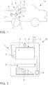
- Figure 1 shows a car 10 as a means of transportation, in which a screen 3 as a display unit of a user interface 1 according to the invention is embedded in the dashboard.
- a sensor 5 is arranged below the screen 3, which spans a detection area 9 in front of the screen 3 in space.
- a loudspeaker 11 is provided for issuing instructions to the user.
- a data memory 8 is also included for providing predefined references for gesture recognition.
- the aforementioned components are connected to an evaluation unit in the form of an electronic control unit 7 in terms of information technology.
- the electronic control unit 7 is also set up to display a graphic content 2 in the form of a menu on the screen 3.
- FIG. 2 shows an overview of components of an embodiment of a user interface according to the invention in an embodiment of a user terminal according to the invention in the form of a smartphone 20.
- a keyboard 6 of the smartphone 20 is partially cut out to allow a view of the components behind it.
- the screen 3 of the smartphone 20 represents the display unit, a microprocessor 7 the evaluation unit, a flash memory 8 the storage means and a loudspeaker 11 a signal generator of the user interface 1 according to the invention.
- an infrared LED bar 5 is a sensor with the microprocessor 7 IT-related. The latter is also coupled to an antenna 17 in order to communicate wirelessly with a wireless infrastructure or other user terminals.
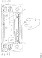
- Figure 3 shows a screen 3 as a display unit, on which a menu 2 for selecting a radio station is shown.
- a menu 2 for selecting a radio station is shown.
- a hand 4 of a user in the detection area 9 of the sensor 5 (both not shown), by means of which the user would like to carry out a 3D gesture for operating the navigation.
- Figure 4 shows possible hand positions and gestures for the interaction with a user interface 1 according to the invention.
- the open palm of the hand 4 points in the direction of the screen 3.
- the fingers of the hand 4 are stretched and slightly spread.
- Part b shows a pointing gesture of the hand 4, in which only the index finger of the hand 4 is stretched, while the other fingers are clenched into a fist.
- Part c shows a typing gesture or click gesture, in which the index finger of the hand 4 is first extended and then folded down in the direction of the screen 3 to activate a function associated with a button.
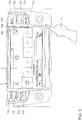
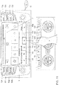
- Figure 5 shows the screen 3 of a user interface, on which a menu 2 for selecting a radio station is displayed as graphic content.
- the hand 4 of the user is located in an upper right edge area of the (not shown) detection area.
- An area marked by a red frame 15 on the screen 3 is assigned to this area.
- To the right of this area are four buttons 12a, 12b, 12c, 12d.
- the buttons 12a, 12b, 12c, 12d are assigned to the functions “navigation”, “traffic reports", “on-board computer”, “main menu” as pushbuttons.
- Four further buttons 12e, 12f, 12g, 12h which are assigned to the functions "radio", “media”, “telephone” and “voice communication", are arranged mirror-symmetrically on the left of the screen 3.
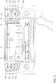
- Figure 6 shows a possibility of outputting a note to the user that his hand 4 remains in the area of the user interface assigned to the buttons 12a, 12b, 12c, 12d.
- the evaluation unit (not shown) begins to insert an optical representation 14a, 14b, 14c, 14d of the buttons 12a, 12b, 12c, 12d horizontally into the menu 2 or to superimpose it on the menu 2.
- Figure 7 shows the in Figure 6 arrangement shown with advanced insertion process.
- Figure 8 shows the in Figure 7 shown arrangement after completing the insertion process.
- the representations 14a, 14b, 14c, 14d and the associated buttons 12a, 12b, 12c, 12d are each at the same height as the screen edge.
- the top button 12a is symbolized by the optical representation 14a.
- the user brings his hand 4 into a partial area of the detection area which is assigned to the optical representation 14a, which is illustrated by a red frame 15.
- the red frame 15 merely symbolizes a process which is also referred to as a "mouse-over event" in the area of graphical user interfaces. All measures known in the prior art for the optical highlighting of buttons can be taken in order to optically acknowledge the described process also for the optical representation 14a.
- the user can now perform a typing gesture or a click gesture with his hand 4.
- the user can change the position of his hand 4 downwards, as a result of which the in Figure 9 shown view corresponding to the traffic reports is created.
- Figure 10 shows a view of an operating step with an alternatively designed user interface.
- the user has brought his hand 4 into a lower area of the detection area (not shown), which is assigned to a lower area of the menu 2 and the screen 3. This area is highlighted by a red frame 15.
- the buttons 12i, 12k, 12l, 12m, 12n and 12p arranged below the screen 3 are assigned to an air conditioning system.
- a loudspeaker / note symbol 16 illustrates the output of an acoustic message, by means of which the user is informed about the entry of his hand 4 into the marked area.
- Figure 11 shows the result of a hand 4 of the user remaining in the in Figure 10 highlighted area.
- the hand 4 is arranged in a partial area of the (not shown) detection area, which is assigned to the air distribution for the footwell (see red frame 15).
- the possibility of a corresponding function call is announced again by the output of an acoustic signal (symbolized by the loudspeaker / note symbol 16).
- the hand 4 of the user could also operate optical representations 14i, 14k, 14l, 14n or 14p in order to control climatic functions associated with them.
- a tactile operation of the buttons 12i, 12k, 12l, 12m, 12n, 12p designed in hardware is of course not affected by this option.
- Figure 12 shows method steps of an embodiment of a method according to the invention.
- step 100 the hand of a user is sensed and in step 200 it is assigned to an area assigned to the button of a user interface. In other words, it is determined that the hand is located in an area which is provided according to the invention for contactless operation of the button.
- step 300 the user is informed that his hand is in the area for the contactless operation of the button.
- an optical representation of the button on a screen of the user interface at height of the button is shown.
- a predefined gesture of a user in this area is detected, which is linked to a function associated with the button. This gesture can be, for example, a typing gesture or a click gesture for actuating the representation.
- the function associated with the button is called in step 500.
- an operating element designed in hardware and intended for tactile operation has been used solely by executing 3D gestures for an associated function call.
Landscapes
- Engineering & Computer Science (AREA)
- General Engineering & Computer Science (AREA)
- Theoretical Computer Science (AREA)
- Human Computer Interaction (AREA)
- Physics & Mathematics (AREA)
- General Physics & Mathematics (AREA)
- User Interface Of Digital Computer (AREA)
Description
Die vorliegende Erfindung betrifft eine Anwenderschnittstelle sowie ein Verfahren zur berührungslosen Bedienung eines in Hardware ausgestalteten Bedienelementes ("Knopf", "Schieberegler", "Dreh-/Drücksteller" etc.) einer Anwenderschnittstelle. Insbesondere betrifft die vorliegende Erfindung ein neues Verfahren zur berührungslosen Interaktion mit einem solchen Knopf.The present invention relates to a user interface and a method for the contactless operation of an operating element configured in hardware (“button”, “slider”, “rotary / push button” etc.) of a user interface. In particular, the present invention relates to a new method for contactless interaction with such a button.
Die Gestenbedienung im freien Raum erfreut sich immer größerer Beliebtheit. Mittels solcher Gesten können Anwender mit Mensch-Maschine-Schnittstellen kommunizieren, ohne körperlichen Kontakt mit der Eingabeeinrichtung zu haben. Beispielsweise über optische und/oder Infrarot-basierte Systeme wird die Geste erkannt und in Steuerbefehle umgewandelt. Bislang beschränkte sich die Gestenbedienung lediglich auf in Software dargestellte Schaltflächen und andere Interaktionsbereiche.Gesture control in free space is becoming increasingly popular. Such gestures enable users to communicate with human-machine interfaces without having physical contact with the input device. For example, the gesture is recognized via optical and / or infrared-based systems and converted into control commands. So far, gesture control has been limited to buttons and other interaction areas displayed in software.
Die technischen Möglichkeiten werden durch den zuvor genannten Stand der Technik lediglich unvollständig ausgeschöpft. Es ist daher eine Aufgabe der vorliegenden Erfindung, den vorstehend aufgezeigten Bedarf zu stillen.The technical possibilities are only incompletely exhausted by the aforementioned prior art. It is therefore an object of the present invention to meet the need outlined above.
Die vorstehend genannte Aufgabe wird erfindungsgemäß durch ein Verfahren mit den Merkmalen gemäß Anspruch 1 sowie durch eine Anwenderschnittstelle mit den Merkmalen gemäß Anspruch 8 gelöst. Zudem werden ein Anwenderendgerät, ein Computerprogrammprodukt, eine Signalfolge und ein Fortbewegungsmittel zur Lösung dieser Aufgabe vorgeschlagen. Das Verfahren dient der berührungslosen Bedienung eines in Hardware ausgestalteten Bedienelementes. Als in Hardware ausgestaltetes Bedienelement (der Einfachheit halber im Weiteren häufig als "Knopf" bezeichnet) sei im Rahmen der vorliegenden Erfindung ein solches Element verstanden, dessen Erscheinung nicht im Wesentlichen durch einen hinter ihm liegenden Bildschirm bestimmt wird, wie es bei transparenten, berührungsempfindlichen Oberflächen sogenannter Touch-Screens der Fall ist. Solche Bedienelemente sind in modernen Fahrzeugen in großer Vielzahl und Variantenvielfalt vorgesehen, um beispielsweise Sitzeinstellungen, Klimaeinstellung, Einstellungen der Musikwiedergabe etc. zu ermöglichen. Lediglich beispielsweise werden die bekannten Formen "Taster", "Druckknopf', "Drehknopf", "Dreh-Drück-Knopf" und "Schieberegler" ("Slider") genannt. Die erfindungsgemäß adressierte Anwenderschnittstelle ist überdies eingerichtet, in einem 3D-Gesten-Modus auch frei im Raum ausgeführte Gesten ("3D-Gesten") zu erkennen und als Steuerbefehle entgegenzunehmen. Hierzu wird in einem ersten Schritt die Hand eines Anwenders sensorisch erfasst. Als Sensor kommen im Stand der Technik insbesondere optische und/oder Infrarot-basierte Systeme zum Einsatz, ohne dass die Erfindung auf diese Ausführungsformen beschränkt ist. Der Sensor hat einen Erfassungsbereich, in welchem er durch die Hand des Anwenders ausgeführte Gesten hinreichend hoch aufgelöst erfassen kann, um sie hinsichtlich vordefinierter Referenzen klassifizieren bzw. beurteilen zu können. In einem zweiten Schritt wird die Hand zu einem dem Knopf zugeordneten Bereich der Anwenderschnittstelle zugeordnet. Mit anderen Worten wird ein Teilbereich des sensorisch überwachten Erfassungsbereiches dem Knopf zugeordnet, so dass auch auf eine mit dem Knopf assoziierte Funktion über den Teilbereich des Erfassungsbereiches zugegriffen werden kann. Bevorzugt korrespondieren der 3D-Erfassungsbereich und ein auf einer Anzeige der Anwenderschnittstelle dargestellter Bereich einer grafischen Benutzeroberfläche derart miteinander, dass einem jeden Bereich auf der grafischen Benutzeroberfläche ein jeweiliger Teilbereich des sensorisch überwachten Erfassungsbereiches entspricht. In diesem Fall ist dem Knopf auch ein entsprechender Bereich auf der grafischen Benutzeroberfläche zugeordnet. Wird nun die Hand in einem dem Knopf zugeordneten Bereich (des Erfassungsbereiches bzw. der grafischen Benutzeroberfläche) zugeordnet, wird ein Hinweis an den Anwender ausgegeben. Mit anderen Worten wird der Anwender über die Tatsache informiert, dass seine Hand denjenigen Erfassungsbereich erreicht hat, welcher dem Knopf zugeordnet ist. Auf diese Weise werden unterschiedliche Bedienschritte ermöglicht, welche im Laufe der vorliegenden Beschreibung der Erfindung im Detail beschrieben werden. Zumindest ist der Anwender durch die vorliegende Erfindung darüber informiert, ob eine berührungslose Interaktion mit dem Knopf aktuell bereits stattfinden kann oder ob seine Hand hierzu erst in den dem Knopf zugeordneten Bereich eindringen muss.The above-mentioned object is achieved according to the invention by a method with the features according to
Hat der Anwender, wie oben beschrieben, seine Hand in dem dem Knopf zugeordneten Bereich angeordnet, kann er eine Geste zum Starten einer dem Knopf zugeordneten Funktion ausführen. Eine solche Geste kann beispielsweise eine Tipp-Geste (auch "Klick-Geste"), eine Zug- und/oder Abwurf (Drag and Drop)-Geste, eine Langdruck (Englisch "Long Press")-Geste o.Ä. sein. Die assoziierte Funktion des Knopfes kann beispielsweise das Aufrufen eines dem Knopf zugeordneten Menüpunktes (z.B. "Navigation", "Radio", "Bordcomputer", "Verkehrsmeldungen" o.Ä.) sein. Auf diese Weise muss der Anwender den Knopf nicht berühren und daher auch nicht seine komfortable Sitzposition verlassen, um die mit dem Knopf assoziierte Funktion zu starten. Auf diese Weise lässt sich die Verkehrssicherheit eines erfindungsgemäß ausgestalteten Fortbewegungsmittels erhöhen, da die Sitzposition des Fahrers weniger stark für die Bedienung des Knopfes verändert werden muss.If, as described above, the user has placed his hand in the area assigned to the button, he can execute a gesture to start a function assigned to the button. Such a gesture can be, for example, a typing gesture (also “click gesture”), a pull and / or drop (drag and drop) gesture, a long press (English “long press”) gesture or the like. be. The associated function of the button can be, for example, calling up a menu item assigned to the button (e.g. "navigation", "radio", "on-board computer", "traffic reports" or the like). In this way, the user does not have to touch the button and therefore does not have to leave his comfortable sitting position in order to start the function associated with the button. In this way, the traffic safety of a means of transportation designed according to the invention can be increased, since the driver's seating position has to be changed less for the operation of the button.
Die Unteransprüche zeigen bevorzugte Weiterbildungen der Erfindung.The subclaims show preferred developments of the invention.
Der dem Knopf zugeordnete Bereich des Erfassungsbereiches kann in einem Randbereich des Erfassungsbereiches liegen. Ein solcher Bereich ist üblicherweise auch einem Randbereich einer auf einer Anzeigeeinheit dargestellten grafischen Benutzeroberfläche zugeordnet. Da innerhalb der Grenzen einer Anzeigeeinheit üblicherweise keine Knöpfe angeordnet sind (Bildschirme sind stets geschlossene Flächen), die Anzeigeeinheiten jedoch häufig durch Hardware-Bedienelemente gesäumt sind, ergibt sich eine besonders intuitiv erfassbare Zuordnung. Besonders intuitiv wird die Zuordnung, wenn lediglich die auf Höhe des Knopfes angeordneten Abschnitte des Randbereiches der Anzeigeeinheit dem Betrachter im Knopf zugeordnet sind und andere Randbereiche anderen Knöpfen zugeordnet sind. Auf diese Weise ergibt sich insbesondere die Möglichkeit, eine Vielzahl bzw. sämtliche die Anzeigeeinheit säumenden Knöpfe erfindungsgemäß durch 3D-Gesten zu bedienen.The area of the detection area assigned to the button can lie in an edge area of the detection area. Such an area is usually also an edge area of a graphic displayed on a display unit Mapped user interface. Since no buttons are usually arranged within the limits of a display unit (screens are always closed areas), but the display units are often lined with hardware operating elements, this results in a particularly intuitive assignment. The assignment becomes particularly intuitive if only the sections of the edge area of the display unit arranged at the button are assigned to the viewer in the button and other edge areas are assigned to other buttons. In this way, there is in particular the possibility of operating a large number or all of the buttons that line the display unit according to the invention by means of 3D gestures.
Das Ausgeben des Hinweises kann beispielsweise auf der Anzeigeeinheit ("dem Bildschirm") erfolgen, indem der dem Knopf zugeordnete Bereich optisch hervorgehoben wird. Beispielsweise kann auch eine optische Repräsentation des Knopfes auf dem Bildschirm angezeigt werden. Dies kann bevorzugt in dem dem Knopf zugeordneten Bereich und außerhalb desselben erfolgen, wobei optional andere Bildschirminhalte überlagert werden. Alternativ oder zusätzlich kann der Hinweis mittels eines elektroakustischen Wandlers ausgegeben werden. Alternativ oder zusätzlich kann der Knopf selbst optisch hervorgehoben werden. Im Stand der Technik werden Knöpfe, welche eine vordefinierte Funktion aufrufen, kostengünstig und betriebssicher mittels Licht-emittierender Dioden (LED) hintergrundbeleuchtet. Eine optische Hervorhebung des Knopfes kann daher beispielsweise durch eine Veränderung der Lichtfarbe und/oder - intensität erfolgen. Letzteres kann beispielsweise durch Modulierung der Energieversorgung zur Erzeugung eines Blinksignals erfolgen.The information can be output on the display unit (“the screen”), for example, by optically highlighting the area assigned to the button. For example, an optical representation of the button can also be displayed on the screen. This can preferably take place in the area assigned to the button and outside of it, with other screen contents optionally being overlaid. Alternatively or additionally, the message can be output using an electroacoustic transducer. Alternatively or additionally, the button itself can be highlighted. In the prior art, buttons that call up a predefined function are backlit inexpensively and reliably using light-emitting diodes (LED). The button can therefore be highlighted, for example, by changing the light color and / or intensity. The latter can be done, for example, by modulating the energy supply to generate a flashing signal.
Nach Ablauf eines vordefinierten Zeitraumes kann der Hinweis beendet bzw. die Einblendung der optischen Repräsentation des Knopfes rückgängig gemacht werden. Bevorzugt kann hierbei die optische Repräsentation des Knopfes in umgekehrter Richtung entfernt werden, in welcher sie eingeblendet wurde. Mit anderen Worten kann bei einem rechts der Anzeigeeinheit angeordneten Knopf die optische Repräsentation nach links in den grafischen Inhalt der Anzeigeeinheit eingeschoben und nach Ablauf der vordefinierten Zeitdauer bzw. einem Austritt der Hand aus dem dem Knopf zugeordneten Bereich der Anwenderschnittstelle nach rechts hinausgeschoben werden.After a predefined period of time has elapsed, the message can be ended or the visual representation of the button can be undone. In this case, the optical representation of the button can preferably be removed in the opposite direction in which it was shown. In other words, in the case of a button arranged to the right of the display unit, the optical representation can be inserted to the left into the graphic content of the display unit and, after the predefined period of time or an exit of the hand from the area of the user interface assigned to the button, can be moved to the right.
Für die optische Darstellung der Repräsentation ergibt sich eine große Vielzahl von Gestaltungsmöglichkeiten, welche nachfolgend lediglich auszugsweise diskutiert wird. Die optische Repräsentation kann beispielsweise als (teilweise) transparente Überlagerung des sonstigen grafischen Inhaltes der Anzeigeeinheit überlagert werden. Auf diese Weise wird der temporäre Charakter der Einblendung hervorgehoben. Alternativ oder zusätzlich kann die optische Repräsentation animiert werden und hierbei unterschiedliche Transparenzwerte, wellenartige Bewegungen und/oder einen ortsveränderlichen Glanz oder "Glow" aufweisen. Zusätzlich zu den vorgenannten Gestaltungsmöglichkeiten, mittels welchen der temporäre Charakter der optischen Repräsentation unterstrichen wird, kann zusätzlich eine optisch ansprechende Gestaltung der Repräsentation erzielt werden.There is a large number of design options for the visual representation of the representation, which are only discussed in part below. The optical representation can, for example, be a (partially) transparent overlay the other graphic content of the display unit are superimposed. In this way, the temporary character of the overlay is emphasized. As an alternative or in addition, the optical representation can be animated and have different transparency values, wave-like movements and / or a positionally variable gloss or "glow". In addition to the aforementioned design options, by means of which the temporary character of the optical representation is underlined, an optically appealing design of the representation can also be achieved.
Gemäß einem zweiten Aspekt der vorliegenden Erfindung wird eine Anwenderschnittstelle vorgeschlagen, welche einen Sensor zum Erkennen frei im Raum ausgeführter Gesten aufweist. Weiter ist eine Anzeigeeinheit (z.B. in Form einer Matrixanzeige oder "Bildschirm") ebenso wie eine Auswerteeinheit zum Erkennen einer Vielzahl von Gesten in Signalen des Sensors vorgesehen. Die Auswerteeinheit kann beispielsweise als elektronisches Steuergerät ausgestaltet sein und einen programmierbaren Prozessor umfassen. Ein neben der Anzeigeeinheit angeordnetes in Hardware ausgestaltetes Bedienelement ist mit zumindest einer vordefinierten Funktion belegt. Mit anderen Worten wird eine der Anzeigeeinheit gegebenenfalls überlagerte berührungsempfindliche Bedienoberfläche im Rahmen der vorliegenden Erfindung nicht als "Knopf verstanden. Erfindungsgemäß ist die Anwenderschnittstelle eingerichtet, im Ansprechen auf eine mittels der Auswerteeinheit erkannte Präsenz in einem dem Knopf zugeordneten 3D-Erfassungsbereich einen Hinweis an den Anwender auszugeben. Für die Merkmale, Merkmalskombination und die sich aus diesen ergebenden Vorteile der erfindungsgemäßen Anwenderschnittstelle gelten die in Verbindung mit dem erfindungsgemäßen Verfahren gemachten Ausführungen derart, dass zur Vermeidung von Wiederholungen auf die obigen Ausführungen verwiesen wird.According to a second aspect of the present invention, a user interface is proposed which has a sensor for recognizing gestures which are carried out freely in space. There is also a display unit (e.g. in the form of a matrix display or "screen") as well as an evaluation unit for recognizing a large number of gestures in signals from the sensor. The evaluation unit can be configured, for example, as an electronic control unit and can include a programmable processor. An operating element configured in hardware and arranged next to the display unit is assigned at least one predefined function. In other words, in the context of the present invention, a touch-sensitive user interface possibly superimposed on the display unit is not understood as a button For the features, combination of features and the advantages of the user interface according to the invention which result from these, the statements made in connection with the method according to the invention apply in such a way that reference is made to the above statements in order to avoid repetitions.
Gemäß einem dritten Aspekt der vorliegenden Erfindung wird ein Anwenderendgerät vorgeschlagen, welches beispielsweise ein mobiles elektronisches Gerät sein kann. Insbesondere werden elektronische Drahtloskommunikationsgeräte (Smartphones, Laptop, Netbook, Tablet-PC etc.) als erfindungsgemäß verwendbare Anwenderendgeräte verstanden. Eine Anwenderschnittstelle ist in das Anwenderendgerät integriert, mittels welcher das Anwenderendgerät zur Durchführung eines Verfahrens gemäß dem erstgenannten Erfindungsaspekt eingerichtet wird. Die Merkmale und Vorteile ergeben sich entsprechend.According to a third aspect of the present invention, a user terminal is proposed, which can be, for example, a mobile electronic device. In particular, electronic wireless communication devices (smartphones, laptops, netbooks, tablet PCs, etc.) are understood as user terminals that can be used according to the invention. A user interface is integrated in the user terminal, by means of which the user terminal is set up to carry out a method according to the first-mentioned aspect of the invention. The characteristics and advantages result accordingly.
Gemäß einem vierten Aspekt der vorliegenden Erfindung wird ein Computerprogrammprodukt (z.B. ein Datenspeicher) vorgeschlagen, auf welchem Instruktionen gespeichert sind, die einen programmierbaren Prozessor einer Anwenderschnittstelle in die Lage versetzen, die Schritte eines Verfahrens gemäß dem erstgenannten Erfindungsaspekt durchzuführen. Das Computerprogrammprodukt kann als CD, DVD, Blue-ray-Disk, Flash-Speicher, Festplatte, RAM/ROM, Cache etc. ausgestaltet sein.According to a fourth aspect of the present invention, a computer program product (e.g. a data memory) is proposed, on which instructions are stored which enable a programmable processor of a user interface to carry out the steps of a method according to the first-mentioned aspect of the invention. The computer program product can be designed as a CD, DVD, Blu-ray disk, flash memory, hard disk, RAM / ROM, cache etc.
Gemäß einem fünften Aspekt der vorliegenden Erfindung wird eine Signalfolge, repräsentierend Instruktionen vorgeschlagen, welche einen programmierbaren Prozessor einer Anwenderschnittstelle in die Lage versetzen, die Schritte eines Verfahrens gemäß dem erstgenannten Erfindungsaspekt durchzuführen. Auf diese Weise wird auch die informationstechnische Bereitstellung der Instruktionen für den Fall unter Schutz gestellt, dass sich die hierzu erforderlichen Speichermittel außerhalb des Geltungsbereiches der beigefügten Ansprüche befinden.According to a fifth aspect of the present invention, a signal sequence representing instructions is proposed which enable a programmable processor of a user interface to carry out the steps of a method according to the first-mentioned aspect of the invention. In this way, the information technology provision of the instructions is also protected in the event that the storage means required for this purpose are outside the scope of the appended claims.
Gemäß einem sechsten Aspekt der vorliegenden Erfindung wird ein Fortbewegungsmittel vorgeschlagen, welches beispielsweise als Pkw, Transporter, Lkw, Land- und/oder Wasserfahrzeug ausgestaltet sein kann. Das Fortbewegungsmittel umfasst eine Anwenderschnittstelle gemäß dem zweitgenannten Erfindungsaspekt, wobei die Anzeigeeinheit als fest in ein Armaturenbrett des Fortbewegungsmittels eingebauter zentraler Bildschirm und/oder als Kombiinstrument des Fortbewegungsmittels ausgestaltet ist. Auf diese Weise werden die in Verbindung mit der erfindungsgemäßen Anwenderschnittstelle erläuterten Merkmale, Merkmalskombinationen und die sich aus diesen ergebenden Vorteile durch das erfindungsgemäße Fortbewegungsmittel verwirklicht.According to a sixth aspect of the present invention, a means of transportation is proposed which can be designed, for example, as a car, transporter, truck, land and / or water vehicle. The means of transportation comprises a user interface according to the second aspect of the invention, the display unit being configured as a central screen permanently installed in an instrument panel of the means of transportation and / or as a combination instrument of the means of transportation. In this way, the features, combinations of features explained in connection with the user interface according to the invention and the advantages resulting therefrom are realized by the means of transportation according to the invention.
Nachfolgend werden Ausführungsbeispiele der Erfindung unter Bezugnahme auf die begleitenden Zeichnungen im Detail beschrieben. In den Zeichnungen ist:
Figur 1- eine schematische Übersicht über Komponenten eines Ausführungsbeispiels einer erfindungsgemäßen Anwenderschnittstelle in einem Ausführungsbeispiel eines erfindungsgemäßen Fortbewegungsmittels;
Figur 2- eine schematische Übersicht über Komponenten eines zweiten Ausführungsbeispiels einer erfindungsgemäßen Anwenderschnittstelle in einem Ausführungsbeispiel eines erfindungsgemäßen Anwenderendgerätes;
Figur 3- eine Darstellung eines ersten Bedienschrittes einer erfindungsgemäßen Anwenderschnittstelle;
Figur 4- eine Auswahl möglicher Handgesten zur Bedienung einer erfindungsgemäßen Anwenderschnittstelle;
Figur 5- eine Darstellung eines Bedienschrittes zur berührungslosen Bedienung eines Knopfes;
Figur 6- eine Darstellung eines Bedienschrittes, welcher sich an den in
Figur 5 Figur 7- eine Darstellung eines Bedienschrittes, welcher sich an den in
Figur 6 Figur 8- eine Darstellung einer Anwenderinteraktion mit einer optischen Repräsentation eines ersten Knopfes;
Figur 9- eine Darstellung einer Anwenderinteraktion mit einer optischen Repräsentation eines zweiten Knopfes;
Figur 10- eine Darstellung eines Bedienschrittes zur berührungslosen Bedienung eines Knopfes gemäß einem zweiten Ausführungsbeispiel einer erfindungsgemäßen Anwenderschnittstelle;
Figur 11- eine Darstellung eines Bedienschrittes, welcher sich an den in
Figur 10 - Figur 12
- ein Flussdiagramm veranschaulichend Schritte eines Ausführungsbeispiels eines erfindungsgemäßen Verfahrens.
- Figure 1
- a schematic overview of components of an embodiment of a user interface according to the invention in an embodiment of a means of transportation according to the invention;
- Figure 2
- a schematic overview of components of a second embodiment of a user interface according to the invention in an embodiment of a user terminal according to the invention;
- Figure 3
- a representation of a first operating step of a user interface according to the invention;
- Figure 4
- a selection of possible hand gestures for operating a user interface according to the invention;
- Figure 5
- a representation of an operating step for contactless operation of a button;
- Figure 6
- a representation of an operating step, which is based on the in
Figure 5 shown connects; - Figure 7
- a representation of an operating step, which is based on the in
Figure 6 shown connects; - Figure 8
- a representation of a user interaction with an optical representation of a first button;
- Figure 9
- a representation of a user interaction with an optical representation of a second button;
- Figure 10
- a representation of an operating step for contactless operation of a button according to a second embodiment of a user interface according to the invention;
- Figure 11
- a representation of an operating step, which is based on the in
Figure 10 shown connects; and - Figure 12
- a flow chart illustrating steps of an embodiment of a method according to the invention.
Auch wenn die erfindungsgemäßen Aspekte und vorteilhaften Ausführungsformen anhand der in Verbindung mit den beigefügten Zeichnungsfiguren erläuterten Ausführungsbeispiele im Detail beschrieben worden sind, sind für den Fachmann Modifikationen und Kombinationen von Merkmalen der dargestellten Ausführungsbeispiele möglich, ohne den Bereich der vorliegenden Erfindung zu verlassen, deren Schutzbereich durch die beigefügten Ansprüche definiert wird.Even if the aspects and advantageous embodiments according to the invention have been described in detail on the basis of the exemplary embodiments explained in conjunction with the attached drawing figures, modifications and combinations of features of the illustrated exemplary embodiments are possible for the person skilled in the art without leaving the scope of the present invention, the scope of protection thereof the appended claims are defined.
- 11
- AnwenderschnittstelleUser interface
- 22nd
- Menümenu
- 33rd
- Bildschirmscreen
- 44th
- Hand des AnwendersHand of the user
- 55
- Infrarot-LED-Leiste/SensorInfrared LED bar / sensor
- 66
- Tastaturkeyboard
- 77
- elektronisches Steuergerät/Prozessorelectronic control unit / processor
- 88th
- DatenspeicherData storage
- 99
- ErfassungsbereichDetection area
- 1010th
- PkwCar
- 1111
- Lautsprecherspeaker
- 1212th
- Knopfstud
- 1414
- Optische RepräsentationOptical representation
- 1515
- roter Rahmenred frame
- 1616
- akustischer Hinweisacoustic warning
- 1717th
- Antenneantenna
- 2020th
- SmartphoneSmartphone
- 100-500100-500
- VerfahrensschritteProcedural steps
Claims (14)
- Method for contactless operation of a control element (12), subsequently called "button", which is configured in hardware, of a user interface (1) in a 3D gesture mode that can be used to operate the user interface (1) by means of gestures carried out freely in space, subsequently called 3D gestures, comprising:- detecting (100) a hand of a user,- assigning (200) the hand to an area of the user interface (1) that is associated with the button (12), responding thereto by- outputting (300) advice (14, 16) to the user indicating that his hand has reached the detection area associated with the button (12), wherein the method is characterized in that it further comprises:- recognizing (400) a predefined gesture of a user in an area associated with the button (12), and- starting (500) a function associated with the button (12).
- Method according to Claim 1, wherein the area associated with the button (12) lies in a marginal area of the detection area (9) and/or in a marginal area of a display unit (3) of the user interface (1).
- Method according to either of the preceding claims, wherein the button (12) is arranged adjacently to a screen of the user interface (1).
- Method according to one of the preceding claims, wherein the advice (14, 16) is output (300)- on a screen and/or- by means of an electroacoustic transducer (11), and/or- by means of visual highlighting of the button (12), in particular by means of an LED.
- Method according to one of the preceding claims, wherein the advice (14, 16) comprises showing a visual representation (14) of the button (12) on a screen (3).
- Method according to Claim 5, wherein the visual representation (14) is shown in a marginal area (13) of the screen (3) that is closest to the button (12).
- Method according to Claim 5 or 6, wherein the showing of the visual representation (14) is ended after a predefined period after the area associated with the button (12) is left.
- User interface comprising- a sensor (5) for recognizing gestures carried out freely in space, subsequently called 3D gestures,- a display unit (3),- an evaluation unit (7) for recognizing a multiplicity of gestures in signals from the sensor (5), and- a control element (12), subsequently called "button", which is configured in hardware and arranged next to the display unit (3),wherein the user interface (1) is geared to respond to a 3D gesture recognized by means of the evaluation unit (7) in an area associated with the button (12) by outputting (300) advice (14, 16) to the user indicating that his hand has reached the detection area associated with the button (12),
wherein the user interface is characterized in that it is further geared to
recognize a predefined gesture of a user in an area associated with the button (12) and
start a function associated with the button (12). - User interface according to Claim 8, wherein the button (12) is configured as a rotary control, switch, slide control or the like.
- User interface according to Claim 8 or 9, wherein the sensor (5) is an optical sensor and/or a sensor operating in the infrared range.
- User terminal (20), in particular electronic wireless communication device, comprising a user interface (1) according to one of Claims 8 to 10.
- Computer program product comprising instructions that, when executed on an evaluation unit (7) of a user interface (1) according to one of Claims 8 to 10, prompt the evaluation unit (7) to perform the steps of a method according to one of Claims 1 to 7.
- Signal sequence representing instructions that, when executed on an evaluation unit (7) of a user interface (1) according to one of Claims 8 to 10, prompt the evaluation unit (7) to perform the steps of a method according to one of Claims 1 to 7.
- Means of transport comprising a user interface (1) according to one of Claims 8 to 10, wherein the display unit (3) is configured as a central screen permanently installed in a dashboard of the means of transport (10) and/or as a combination instrument of the means of transport (10).
Applications Claiming Priority (2)
| Application Number | Priority Date | Filing Date | Title |
|---|---|---|---|
| DE102014202834.5A DE102014202834A1 (en) | 2014-02-17 | 2014-02-17 | User interface and method for contactless operation of a hardware-designed control element in a 3D gesture mode |
| PCT/EP2015/052601 WO2015121187A1 (en) | 2014-02-17 | 2015-02-09 | User interface and method for contactlessly operating a hardware operating element in a 3-d gesture mode |
Publications (2)
| Publication Number | Publication Date |
|---|---|
| EP3108331A1 EP3108331A1 (en) | 2016-12-28 |
| EP3108331B1 true EP3108331B1 (en) | 2020-04-08 |
Family
ID=52484454
Family Applications (1)
| Application Number | Title | Priority Date | Filing Date |
|---|---|---|---|
| EP15705233.3A Active EP3108331B1 (en) | 2014-02-17 | 2015-02-09 | User interface and method for contactlessly operating a hardware operating element in a 3-d gesture mode |
Country Status (5)
| Country | Link |
|---|---|
| US (1) | US11119576B2 (en) |
| EP (1) | EP3108331B1 (en) |
| CN (1) | CN105992990B (en) |
| DE (1) | DE102014202834A1 (en) |
| WO (1) | WO2015121187A1 (en) |
Cited By (1)
| Publication number | Priority date | Publication date | Assignee | Title |
|---|---|---|---|---|
| EP3399762B1 (en) * | 2017-05-02 | 2023-07-12 | Harman International Industries, Incorporated | Portable hub with digital video recorder |
Families Citing this family (7)
| Publication number | Priority date | Publication date | Assignee | Title |
|---|---|---|---|---|
| DE102016202455A1 (en) | 2016-02-17 | 2017-08-17 | Volkswagen Aktiengesellschaft | User interface, means of locomotion and method for classifying a user gesture executed freely in space |
| WO2017200553A1 (en) * | 2016-05-20 | 2017-11-23 | Ford Global Technologies, Llc | Sign language inputs to a vehicle user interface |
| CN106502570B (en) * | 2016-10-25 | 2020-07-31 | 科世达(上海)管理有限公司 | Gesture recognition method and device and vehicle-mounted system |
| US10732812B2 (en) | 2018-07-06 | 2020-08-04 | Lindsay Corporation | Computer-implemented methods, computer-readable media and electronic devices for virtual control of agricultural devices |
| DE102019119073A1 (en) * | 2019-07-15 | 2021-01-21 | Evga Corporation | Keyboard device and computer control system therefor |
| US11460626B2 (en) * | 2019-07-29 | 2022-10-04 | Waymo Llc | Autonomous vehicle console |
| DE102019121843A1 (en) * | 2019-08-13 | 2021-02-18 | B.Braun Avitum Ag | Interface for a medical device with an adaptive actuation sensor |
Citations (1)
| Publication number | Priority date | Publication date | Assignee | Title |
|---|---|---|---|---|
| DE102009038895A1 (en) * | 2009-08-26 | 2010-09-16 | Audi Ag | Method for supporting operator during operation of e.g. control device of driver assistance system in passenger car, involves presenting information about executable control action during identification |
Family Cites Families (22)
| Publication number | Priority date | Publication date | Assignee | Title |
|---|---|---|---|---|
| EP1222794A1 (en) * | 1999-10-21 | 2002-07-17 | Siemens Aktiengesellschaft | Method and arrangement for controlling an electronic appliance |
| US8482535B2 (en) * | 1999-11-08 | 2013-07-09 | Apple Inc. | Programmable tactile touch screen displays and man-machine interfaces for improved vehicle instrumentation and telematics |
| KR100575906B1 (en) * | 2002-10-25 | 2006-05-02 | 미츠비시 후소 트럭 앤드 버스 코포레이션 | Hand pattern switching apparatus |
| JP4311190B2 (en) * | 2003-12-17 | 2009-08-12 | 株式会社デンソー | In-vehicle device interface |
| US7676754B2 (en) * | 2004-05-04 | 2010-03-09 | International Business Machines Corporation | Method and program product for resolving ambiguities through fading marks in a user interface |
| DE102005005411B4 (en) * | 2005-02-05 | 2022-12-22 | Volkswagen Ag | Motor vehicle with an operating element |
| DE102006037156A1 (en) | 2006-03-22 | 2007-09-27 | Volkswagen Ag | Interactive operating device and method for operating the interactive operating device |
| DE102006059032B4 (en) * | 2006-12-14 | 2009-08-27 | Volkswagen Ag | Operating device of a motor vehicle and method for detecting user inputs |
| US8519964B2 (en) * | 2007-01-07 | 2013-08-27 | Apple Inc. | Portable multifunction device, method, and graphical user interface supporting user navigations of graphical objects on a touch screen display |
| DE102009008041A1 (en) | 2009-02-09 | 2010-08-12 | Volkswagen Ag | Method for operating a motor vehicle with a touchscreen |
| RU2523172C2 (en) * | 2009-12-18 | 2014-07-20 | Хонда Мотор Ко., Лтд. | Transformable panel for tactile control |
| US8432301B2 (en) * | 2010-08-10 | 2013-04-30 | Mckesson Financial Holdings | Gesture-enabled keyboard and associated apparatus and computer-readable storage medium |
| KR101896947B1 (en) * | 2011-02-23 | 2018-10-31 | 엘지이노텍 주식회사 | An apparatus and method for inputting command using gesture |
| DE102011116187A1 (en) | 2011-10-14 | 2013-04-18 | Volkswagen Aktiengesellschaft | Method for providing user interface for interaction with e.g. infotainment system, in vehicle, involves expanding region in which graphic object e.g. electronic log book, is displayed on touch screen by detected gesture for page turning |
| KR101880240B1 (en) * | 2011-12-28 | 2018-07-23 | 브리티쉬 텔리커뮤니케이션즈 파블릭 리미티드 캄퍼니 | Mobile terminal and method for controlling operation thereof |
| CN104010864B (en) * | 2011-12-29 | 2016-10-26 | 英特尔公司 | Configurable control panel |
| DE102012000263A1 (en) | 2012-01-10 | 2013-07-11 | Daimler Ag | A method and apparatus for operating functions in a vehicle using gestures executed in three-dimensional space and related computer program product |
| EP2631760A1 (en) * | 2012-02-24 | 2013-08-28 | Research In Motion Limited | Method and apparatus for providing a user interface on a device enabling selection of operations to be performed in relation to content |
| AU2013204058A1 (en) * | 2012-06-28 | 2014-01-16 | Apolon IVANKOVIC | An interface system for a computing device and a method of interfacing with a computing device |
| CN103076966B (en) * | 2012-11-02 | 2015-07-29 | 网易(杭州)网络有限公司 | The method and apparatus of menu is unlocked by performing gesture on the touchscreen |
| JP6202810B2 (en) * | 2012-12-04 | 2017-09-27 | アルパイン株式会社 | Gesture recognition apparatus and method, and program |
| CN103303224B (en) * | 2013-06-18 | 2015-04-15 | 桂林电子科技大学 | Vehicle-mounted equipment gesture control system and usage method thereof |
-
2014
- 2014-02-17 DE DE102014202834.5A patent/DE102014202834A1/en not_active Withdrawn
-
2015
- 2015-02-09 US US15/503,295 patent/US11119576B2/en active Active
- 2015-02-09 EP EP15705233.3A patent/EP3108331B1/en active Active
- 2015-02-09 CN CN201580007947.8A patent/CN105992990B/en active Active
- 2015-02-09 WO PCT/EP2015/052601 patent/WO2015121187A1/en active Application Filing
Patent Citations (1)
| Publication number | Priority date | Publication date | Assignee | Title |
|---|---|---|---|---|
| DE102009038895A1 (en) * | 2009-08-26 | 2010-09-16 | Audi Ag | Method for supporting operator during operation of e.g. control device of driver assistance system in passenger car, involves presenting information about executable control action during identification |
Cited By (1)
| Publication number | Priority date | Publication date | Assignee | Title |
|---|---|---|---|---|
| EP3399762B1 (en) * | 2017-05-02 | 2023-07-12 | Harman International Industries, Incorporated | Portable hub with digital video recorder |
Also Published As
| Publication number | Publication date |
|---|---|
| DE102014202834A1 (en) | 2015-09-03 |
| CN105992990A (en) | 2016-10-05 |
| US20170242491A1 (en) | 2017-08-24 |
| EP3108331A1 (en) | 2016-12-28 |
| US11119576B2 (en) | 2021-09-14 |
| CN105992990B (en) | 2020-09-11 |
| WO2015121187A1 (en) | 2015-08-20 |
Similar Documents
| Publication | Publication Date | Title |
|---|---|---|
| EP3108331B1 (en) | User interface and method for contactlessly operating a hardware operating element in a 3-d gesture mode | |
| EP2930049B1 (en) | User interface and method for adapting a view on a display unit | |
| EP3105077B1 (en) | Device and method for signalling a successful gesture input | |
| EP3097468A1 (en) | User interface and method for adapting a view of a display unit | |
| EP3358454B1 (en) | User interface, vehicle and method for user distinguishing | |
| DE102015210130A1 (en) | Means of transport, user interface and method of assisting a user in interacting with a user interface | |
| DE102013000069B4 (en) | Motor vehicle user interface with a control element for detecting a control action | |
| EP3040808B1 (en) | Means of locomotion, user interface and method for defining a tile on a display device | |
| EP2030828B9 (en) | Multimodal operating system and method to operate components and functions in a vehicle | |
| EP3234749B1 (en) | User interface and method for customising a dash display in a vehicle | |
| EP3108333B1 (en) | User interface and method for assisting a user in the operation of a user interface | |
| EP3114545B1 (en) | User interface and method for operating a user interface using gestures performed freely in a space | |
| DE102018204223A1 (en) | Mobile, portable operating device for operating a device wirelessly coupled to the operating device, and method for operating a device using a mobile, portable operating device | |
| EP3040842B1 (en) | User interface and method for hybrid use of a display unit of a means of locomotion | |
| EP3108332A1 (en) | User interface and method for switching from a first operating mode of a user interface to a 3d gesture mode | |
| EP3426516A1 (en) | Operating device and method for detecting a user selection of at least one operating function of the operating device | |
| EP2917062B1 (en) | Method for displaying information in a vehicle, and a device for controlling the display | |
| DE102019129396A1 (en) | Graphical user interface, means of transportation and method for operating a graphical user interface for a means of transportation | |
| DE102015222682A1 (en) | Method for activating a control element of a motor vehicle and operating system for a motor vehicle | |
| DE102013214326A1 (en) | Method for operating an input device, input device | |
| DE102015212850A1 (en) | User interface and method for assisting a user in interacting with a user interface | |
| EP3093182A1 (en) | Means of locomotion, working machine, user interface and method for displaying the content of a first display device on a second display device | |
| EP3040836B1 (en) | Means of locomotion, user interface and method for reducing a light emission from a display device of a means of locomotion | |
| DE102014111749A1 (en) | Method and device for controlling a technical device | |
| DE102019129392A1 (en) | Graphical user interface, means of transportation and method for operating a graphical user interface for a means of transportation |
Legal Events
| Date | Code | Title | Description |
|---|---|---|---|
| STAA | Information on the status of an ep patent application or granted ep patent |
Free format text: STATUS: THE INTERNATIONAL PUBLICATION HAS BEEN MADE |
|
| PUAI | Public reference made under article 153(3) epc to a published international application that has entered the european phase |
Free format text: ORIGINAL CODE: 0009012 |
|
| STAA | Information on the status of an ep patent application or granted ep patent |
Free format text: STATUS: REQUEST FOR EXAMINATION WAS MADE |
|
| 17P | Request for examination filed |
Effective date: 20160919 |
|
| AK | Designated contracting states |
Kind code of ref document: A1 Designated state(s): AL AT BE BG CH CY CZ DE DK EE ES FI FR GB GR HR HU IE IS IT LI LT LU LV MC MK MT NL NO PL PT RO RS SE SI SK SM TR |
|
| AX | Request for extension of the european patent |
Extension state: BA ME |
|
| STAA | Information on the status of an ep patent application or granted ep patent |
Free format text: STATUS: EXAMINATION IS IN PROGRESS |
|
| 17Q | First examination report despatched |
Effective date: 20181108 |
|
| GRAP | Despatch of communication of intention to grant a patent |
Free format text: ORIGINAL CODE: EPIDOSNIGR1 |
|
| STAA | Information on the status of an ep patent application or granted ep patent |
Free format text: STATUS: GRANT OF PATENT IS INTENDED |
|
| INTG | Intention to grant announced |
Effective date: 20200102 |
|
| GRAS | Grant fee paid |
Free format text: ORIGINAL CODE: EPIDOSNIGR3 |
|
| GRAA | (expected) grant |
Free format text: ORIGINAL CODE: 0009210 |
|
| STAA | Information on the status of an ep patent application or granted ep patent |
Free format text: STATUS: THE PATENT HAS BEEN GRANTED |
|
| AK | Designated contracting states |
Kind code of ref document: B1 Designated state(s): AL AT BE BG CH CY CZ DE DK EE ES FI FR GB GR HR HU IE IS IT LI LT LU LV MC MK MT NL NO PL PT RO RS SE SI SK SM TR |
|
| AX | Request for extension of the european patent |
Extension state: BA ME |
|
| REG | Reference to a national code |
Ref country code: AT Ref legal event code: REF Ref document number: 1255255 Country of ref document: AT Kind code of ref document: T Effective date: 20200415 Ref country code: CH Ref legal event code: EP |
|
| REG | Reference to a national code |
Ref country code: DE Ref legal event code: R096 Ref document number: 502015012215 Country of ref document: DE |
|
| REG | Reference to a national code |
Ref country code: IE Ref legal event code: FG4D Free format text: LANGUAGE OF EP DOCUMENT: GERMAN |
|
| REG | Reference to a national code |
Ref country code: NL Ref legal event code: MP Effective date: 20200408 |
|
| REG | Reference to a national code |
Ref country code: LT Ref legal event code: MG4D |
|
| PG25 | Lapsed in a contracting state [announced via postgrant information from national office to epo] |
Ref country code: PT Free format text: LAPSE BECAUSE OF FAILURE TO SUBMIT A TRANSLATION OF THE DESCRIPTION OR TO PAY THE FEE WITHIN THE PRESCRIBED TIME-LIMIT Effective date: 20200817 Ref country code: IS Free format text: LAPSE BECAUSE OF FAILURE TO SUBMIT A TRANSLATION OF THE DESCRIPTION OR TO PAY THE FEE WITHIN THE PRESCRIBED TIME-LIMIT Effective date: 20200808 Ref country code: SE Free format text: LAPSE BECAUSE OF FAILURE TO SUBMIT A TRANSLATION OF THE DESCRIPTION OR TO PAY THE FEE WITHIN THE PRESCRIBED TIME-LIMIT Effective date: 20200408 Ref country code: FI Free format text: LAPSE BECAUSE OF FAILURE TO SUBMIT A TRANSLATION OF THE DESCRIPTION OR TO PAY THE FEE WITHIN THE PRESCRIBED TIME-LIMIT Effective date: 20200408 Ref country code: LT Free format text: LAPSE BECAUSE OF FAILURE TO SUBMIT A TRANSLATION OF THE DESCRIPTION OR TO PAY THE FEE WITHIN THE PRESCRIBED TIME-LIMIT Effective date: 20200408 Ref country code: NO Free format text: LAPSE BECAUSE OF FAILURE TO SUBMIT A TRANSLATION OF THE DESCRIPTION OR TO PAY THE FEE WITHIN THE PRESCRIBED TIME-LIMIT Effective date: 20200708 Ref country code: GR Free format text: LAPSE BECAUSE OF FAILURE TO SUBMIT A TRANSLATION OF THE DESCRIPTION OR TO PAY THE FEE WITHIN THE PRESCRIBED TIME-LIMIT Effective date: 20200709 Ref country code: NL Free format text: LAPSE BECAUSE OF FAILURE TO SUBMIT A TRANSLATION OF THE DESCRIPTION OR TO PAY THE FEE WITHIN THE PRESCRIBED TIME-LIMIT Effective date: 20200408 |
|
| PG25 | Lapsed in a contracting state [announced via postgrant information from national office to epo] |
Ref country code: HR Free format text: LAPSE BECAUSE OF FAILURE TO SUBMIT A TRANSLATION OF THE DESCRIPTION OR TO PAY THE FEE WITHIN THE PRESCRIBED TIME-LIMIT Effective date: 20200408 Ref country code: LV Free format text: LAPSE BECAUSE OF FAILURE TO SUBMIT A TRANSLATION OF THE DESCRIPTION OR TO PAY THE FEE WITHIN THE PRESCRIBED TIME-LIMIT Effective date: 20200408 Ref country code: RS Free format text: LAPSE BECAUSE OF FAILURE TO SUBMIT A TRANSLATION OF THE DESCRIPTION OR TO PAY THE FEE WITHIN THE PRESCRIBED TIME-LIMIT Effective date: 20200408 Ref country code: BG Free format text: LAPSE BECAUSE OF FAILURE TO SUBMIT A TRANSLATION OF THE DESCRIPTION OR TO PAY THE FEE WITHIN THE PRESCRIBED TIME-LIMIT Effective date: 20200708 |
|
| PG25 | Lapsed in a contracting state [announced via postgrant information from national office to epo] |
Ref country code: AL Free format text: LAPSE BECAUSE OF FAILURE TO SUBMIT A TRANSLATION OF THE DESCRIPTION OR TO PAY THE FEE WITHIN THE PRESCRIBED TIME-LIMIT Effective date: 20200408 |
|
| REG | Reference to a national code |
Ref country code: DE Ref legal event code: R097 Ref document number: 502015012215 Country of ref document: DE |
|
| PG25 | Lapsed in a contracting state [announced via postgrant information from national office to epo] |
Ref country code: ES Free format text: LAPSE BECAUSE OF FAILURE TO SUBMIT A TRANSLATION OF THE DESCRIPTION OR TO PAY THE FEE WITHIN THE PRESCRIBED TIME-LIMIT Effective date: 20200408 Ref country code: EE Free format text: LAPSE BECAUSE OF FAILURE TO SUBMIT A TRANSLATION OF THE DESCRIPTION OR TO PAY THE FEE WITHIN THE PRESCRIBED TIME-LIMIT Effective date: 20200408 Ref country code: RO Free format text: LAPSE BECAUSE OF FAILURE TO SUBMIT A TRANSLATION OF THE DESCRIPTION OR TO PAY THE FEE WITHIN THE PRESCRIBED TIME-LIMIT Effective date: 20200408 Ref country code: IT Free format text: LAPSE BECAUSE OF FAILURE TO SUBMIT A TRANSLATION OF THE DESCRIPTION OR TO PAY THE FEE WITHIN THE PRESCRIBED TIME-LIMIT Effective date: 20200408 Ref country code: DK Free format text: LAPSE BECAUSE OF FAILURE TO SUBMIT A TRANSLATION OF THE DESCRIPTION OR TO PAY THE FEE WITHIN THE PRESCRIBED TIME-LIMIT Effective date: 20200408 Ref country code: CZ Free format text: LAPSE BECAUSE OF FAILURE TO SUBMIT A TRANSLATION OF THE DESCRIPTION OR TO PAY THE FEE WITHIN THE PRESCRIBED TIME-LIMIT Effective date: 20200408 Ref country code: SM Free format text: LAPSE BECAUSE OF FAILURE TO SUBMIT A TRANSLATION OF THE DESCRIPTION OR TO PAY THE FEE WITHIN THE PRESCRIBED TIME-LIMIT Effective date: 20200408 |
|
| PLBE | No opposition filed within time limit |
Free format text: ORIGINAL CODE: 0009261 |
|
| STAA | Information on the status of an ep patent application or granted ep patent |
Free format text: STATUS: NO OPPOSITION FILED WITHIN TIME LIMIT |
|
| PG25 | Lapsed in a contracting state [announced via postgrant information from national office to epo] |
Ref country code: SK Free format text: LAPSE BECAUSE OF FAILURE TO SUBMIT A TRANSLATION OF THE DESCRIPTION OR TO PAY THE FEE WITHIN THE PRESCRIBED TIME-LIMIT Effective date: 20200408 Ref country code: PL Free format text: LAPSE BECAUSE OF FAILURE TO SUBMIT A TRANSLATION OF THE DESCRIPTION OR TO PAY THE FEE WITHIN THE PRESCRIBED TIME-LIMIT Effective date: 20200408 |
|
| 26N | No opposition filed |
Effective date: 20210112 |
|
| PG25 | Lapsed in a contracting state [announced via postgrant information from national office to epo] |
Ref country code: SI Free format text: LAPSE BECAUSE OF FAILURE TO SUBMIT A TRANSLATION OF THE DESCRIPTION OR TO PAY THE FEE WITHIN THE PRESCRIBED TIME-LIMIT Effective date: 20200408 |
|
| PG25 | Lapsed in a contracting state [announced via postgrant information from national office to epo] |
Ref country code: MC Free format text: LAPSE BECAUSE OF FAILURE TO SUBMIT A TRANSLATION OF THE DESCRIPTION OR TO PAY THE FEE WITHIN THE PRESCRIBED TIME-LIMIT Effective date: 20200408 |
|
| REG | Reference to a national code |
Ref country code: BE Ref legal event code: MM Effective date: 20210228 |
|
| PG25 | Lapsed in a contracting state [announced via postgrant information from national office to epo] |
Ref country code: LI Free format text: LAPSE BECAUSE OF NON-PAYMENT OF DUE FEES Effective date: 20210228 Ref country code: LU Free format text: LAPSE BECAUSE OF NON-PAYMENT OF DUE FEES Effective date: 20210209 Ref country code: CH Free format text: LAPSE BECAUSE OF NON-PAYMENT OF DUE FEES Effective date: 20210228 |
|
| PG25 | Lapsed in a contracting state [announced via postgrant information from national office to epo] |
Ref country code: IE Free format text: LAPSE BECAUSE OF NON-PAYMENT OF DUE FEES Effective date: 20210209 |
|
| REG | Reference to a national code |
Ref country code: AT Ref legal event code: MM01 Ref document number: 1255255 Country of ref document: AT Kind code of ref document: T Effective date: 20210209 |
|
| PG25 | Lapsed in a contracting state [announced via postgrant information from national office to epo] |
Ref country code: AT Free format text: LAPSE BECAUSE OF NON-PAYMENT OF DUE FEES Effective date: 20210209 |
|
| PG25 | Lapsed in a contracting state [announced via postgrant information from national office to epo] |
Ref country code: BE Free format text: LAPSE BECAUSE OF NON-PAYMENT OF DUE FEES Effective date: 20210228 |
|
| PG25 | Lapsed in a contracting state [announced via postgrant information from national office to epo] |
Ref country code: HU Free format text: LAPSE BECAUSE OF FAILURE TO SUBMIT A TRANSLATION OF THE DESCRIPTION OR TO PAY THE FEE WITHIN THE PRESCRIBED TIME-LIMIT; INVALID AB INITIO Effective date: 20150209 |
|
| P01 | Opt-out of the competence of the unified patent court (upc) registered |
Effective date: 20230523 |
|
| PG25 | Lapsed in a contracting state [announced via postgrant information from national office to epo] |
Ref country code: CY Free format text: LAPSE BECAUSE OF FAILURE TO SUBMIT A TRANSLATION OF THE DESCRIPTION OR TO PAY THE FEE WITHIN THE PRESCRIBED TIME-LIMIT Effective date: 20200408 |
|
| PG25 | Lapsed in a contracting state [announced via postgrant information from national office to epo] |
Ref country code: MK Free format text: LAPSE BECAUSE OF FAILURE TO SUBMIT A TRANSLATION OF THE DESCRIPTION OR TO PAY THE FEE WITHIN THE PRESCRIBED TIME-LIMIT Effective date: 20200408 |
|
| PGFP | Annual fee paid to national office [announced via postgrant information from national office to epo] |
Ref country code: DE Payment date: 20240229 Year of fee payment: 10 Ref country code: GB Payment date: 20240220 Year of fee payment: 10 |
|
| PGFP | Annual fee paid to national office [announced via postgrant information from national office to epo] |
Ref country code: FR Payment date: 20240226 Year of fee payment: 10 |