EP3108154B2 - Verfahren zum betreiben eines triebstranges und triebstrang - Google Patents
Verfahren zum betreiben eines triebstranges und triebstrang Download PDFInfo
- Publication number
- EP3108154B2 EP3108154B2 EP14733962.6A EP14733962A EP3108154B2 EP 3108154 B2 EP3108154 B2 EP 3108154B2 EP 14733962 A EP14733962 A EP 14733962A EP 3108154 B2 EP3108154 B2 EP 3108154B2
- Authority
- EP
- European Patent Office
- Prior art keywords
- drive
- differential
- speed
- machine
- gear
- Prior art date
- Legal status (The legal status is an assumption and is not a legal conclusion. Google has not performed a legal analysis and makes no representation as to the accuracy of the status listed.)
- Active
Links
Images


Classifications
-
- G—PHYSICS
- G05—CONTROLLING; REGULATING
- G05D—SYSTEMS FOR CONTROLLING OR REGULATING NON-ELECTRIC VARIABLES
- G05D13/00—Control of linear speed; Control of angular speed; Control of acceleration or deceleration, e.g. of a prime mover
- G05D13/64—Compensating the speed difference between engines meshing by a differential gearing or the speed difference between a controlling shaft and a controlled shaft
-
- F—MECHANICAL ENGINEERING; LIGHTING; HEATING; WEAPONS; BLASTING
- F16—ENGINEERING ELEMENTS AND UNITS; GENERAL MEASURES FOR PRODUCING AND MAINTAINING EFFECTIVE FUNCTIONING OF MACHINES OR INSTALLATIONS; THERMAL INSULATION IN GENERAL
- F16H—GEARING
- F16H3/00—Toothed gearings for conveying rotary motion with variable gear ratio or for reversing rotary motion
- F16H3/44—Toothed gearings for conveying rotary motion with variable gear ratio or for reversing rotary motion using gears having orbital motion
- F16H3/72—Toothed gearings for conveying rotary motion with variable gear ratio or for reversing rotary motion using gears having orbital motion with a secondary drive, e.g. regulating motor, in order to vary speed continuously
- F16H3/724—Toothed gearings for conveying rotary motion with variable gear ratio or for reversing rotary motion using gears having orbital motion with a secondary drive, e.g. regulating motor, in order to vary speed continuously using externally powered electric machines
-
- F—MECHANICAL ENGINEERING; LIGHTING; HEATING; WEAPONS; BLASTING
- F03—MACHINES OR ENGINES FOR LIQUIDS; WIND, SPRING, OR WEIGHT MOTORS; PRODUCING MECHANICAL POWER OR A REACTIVE PROPULSIVE THRUST, NOT OTHERWISE PROVIDED FOR
- F03D—WIND MOTORS
- F03D15/00—Transmission of mechanical power
-
- F—MECHANICAL ENGINEERING; LIGHTING; HEATING; WEAPONS; BLASTING
- F03—MACHINES OR ENGINES FOR LIQUIDS; WIND, SPRING, OR WEIGHT MOTORS; PRODUCING MECHANICAL POWER OR A REACTIVE PROPULSIVE THRUST, NOT OTHERWISE PROVIDED FOR
- F03D—WIND MOTORS
- F03D15/00—Transmission of mechanical power
- F03D15/10—Transmission of mechanical power using gearing not limited to rotary motion, e.g. with oscillating or reciprocating members
-
- F—MECHANICAL ENGINEERING; LIGHTING; HEATING; WEAPONS; BLASTING
- F03—MACHINES OR ENGINES FOR LIQUIDS; WIND, SPRING, OR WEIGHT MOTORS; PRODUCING MECHANICAL POWER OR A REACTIVE PROPULSIVE THRUST, NOT OTHERWISE PROVIDED FOR
- F03D—WIND MOTORS
- F03D7/00—Controlling wind motors
- F03D7/02—Controlling wind motors the wind motors having rotation axis substantially parallel to the air flow entering the rotor
- F03D7/0276—Controlling wind motors the wind motors having rotation axis substantially parallel to the air flow entering the rotor controlling rotor speed, e.g. variable speed
-
- F—MECHANICAL ENGINEERING; LIGHTING; HEATING; WEAPONS; BLASTING
- F03—MACHINES OR ENGINES FOR LIQUIDS; WIND, SPRING, OR WEIGHT MOTORS; PRODUCING MECHANICAL POWER OR A REACTIVE PROPULSIVE THRUST, NOT OTHERWISE PROVIDED FOR
- F03D—WIND MOTORS
- F03D7/00—Controlling wind motors
- F03D7/02—Controlling wind motors the wind motors having rotation axis substantially parallel to the air flow entering the rotor
- F03D7/04—Automatic control; Regulation
-
- F—MECHANICAL ENGINEERING; LIGHTING; HEATING; WEAPONS; BLASTING
- F03—MACHINES OR ENGINES FOR LIQUIDS; WIND, SPRING, OR WEIGHT MOTORS; PRODUCING MECHANICAL POWER OR A REACTIVE PROPULSIVE THRUST, NOT OTHERWISE PROVIDED FOR
- F03D—WIND MOTORS
- F03D9/00—Adaptations of wind motors for special use; Combinations of wind motors with apparatus driven thereby; Wind motors specially adapted for installation in particular locations
- F03D9/20—Wind motors characterised by the driven apparatus
- F03D9/25—Wind motors characterised by the driven apparatus the apparatus being an electrical generator
- F03D9/255—Wind motors characterised by the driven apparatus the apparatus being an electrical generator connected to electrical distribution networks; Arrangements therefor
-
- H—ELECTRICITY
- H02—GENERATION; CONVERSION OR DISTRIBUTION OF ELECTRIC POWER
- H02P—CONTROL OR REGULATION OF ELECTRIC MOTORS, ELECTRIC GENERATORS OR DYNAMO-ELECTRIC CONVERTERS; CONTROLLING TRANSFORMERS, REACTORS OR CHOKE COILS
- H02P9/00—Arrangements for controlling electric generators for the purpose of obtaining a desired output
-
- F—MECHANICAL ENGINEERING; LIGHTING; HEATING; WEAPONS; BLASTING
- F05—INDEXING SCHEMES RELATING TO ENGINES OR PUMPS IN VARIOUS SUBCLASSES OF CLASSES F01-F04
- F05B—INDEXING SCHEME RELATING TO WIND, SPRING, WEIGHT, INERTIA OR LIKE MOTORS, TO MACHINES OR ENGINES FOR LIQUIDS COVERED BY SUBCLASSES F03B, F03D AND F03G
- F05B2260/00—Function
- F05B2260/40—Transmission of power
- F05B2260/403—Transmission of power through the shape of the drive components
- F05B2260/4031—Transmission of power through the shape of the drive components as in toothed gearing
- F05B2260/40311—Transmission of power through the shape of the drive components as in toothed gearing of the epicyclic, planetary or differential type
-
- Y—GENERAL TAGGING OF NEW TECHNOLOGICAL DEVELOPMENTS; GENERAL TAGGING OF CROSS-SECTIONAL TECHNOLOGIES SPANNING OVER SEVERAL SECTIONS OF THE IPC; TECHNICAL SUBJECTS COVERED BY FORMER USPC CROSS-REFERENCE ART COLLECTIONS [XRACs] AND DIGESTS
- Y02—TECHNOLOGIES OR APPLICATIONS FOR MITIGATION OR ADAPTATION AGAINST CLIMATE CHANGE
- Y02E—REDUCTION OF GREENHOUSE GAS [GHG] EMISSIONS, RELATED TO ENERGY GENERATION, TRANSMISSION OR DISTRIBUTION
- Y02E10/00—Energy generation through renewable energy sources
- Y02E10/70—Wind energy
- Y02E10/72—Wind turbines with rotation axis in wind direction
Definitions
- the invention relates to a method for operating a drive train with a drive shaft, an electric drive machine connected to a power grid, operable as a motor and generator, and with a differential gear with three input and output drives, wherein one output is connected to the drive shaft, a drive is connected to the drive machine, and a second drive is connected to a differential drive.
- the invention further relates to a drive train with a drive shaft, an electric drive machine connected to a power grid, operable as a motor and generator, and with a differential gear with three input and output drives, one output being connected to the drive shaft, one drive to the drive machine, and a second drive to an electric differential drive.
- WO 2010/101467 A discloses a drive train for a vehicle, with a differential and two electric machines, which can be operated either as a motor or as a generator.
- a general problem of working machines is efficient variable speed operation.
- electric machines are used as an example of drive machines, but the principle applies to all possible types of drive machines, such as internal combustion engines.
- the most commonly used electric drives today are three-phase machines, such as asynchronous motors and synchronous motors.
- the invention is based on the object of specifying a method and a device of the type mentioned at the outset, in which a change in the delivery rate of the conveying device is possible with a simple structure.
- the core of a differential system is a differential gear, which in a simple design is a simple planetary gear stage with three inputs and outputs, with one output connected to the drive shaft of a working machine, a first drive to the drive machine and a second drive to a differential drive.
- This allows the working machine to be operated at variable speeds while the drive machine has a constant speed, as the differential drive compensates for the speed difference.
- the amount of material delivered by the working machine can be increased by increasing the constant power of the drive machine through the variable power of the differential drive.
- inverter usually used for an electric differential drive is replaced by a rectifier, this is advantageous because it usually has a higher efficiency than an inverter and is also much more robust and cost-effective.
- the invention can be used, for example, in storage power plants.
- a three-phase machine must therefore be designed to be large enough to be able to deliver a drive torque corresponding to the nominal torque from standstill, and is therefore often oversized. For this reason, instead of being connected directly to a network, electrical machines are often designed as a variable speed drive in combination with a frequency converter. This allows starting with a high torque from zero speed without putting a strain on the network, but the solution is expensive and involves significant losses in efficiency.
- the gear ratio of the differential gear can be set to 1.
- the differential drive can be used to drive the entire drive train or to bring the drive machine to synchronous speed and subsequently synchronize it with the network.
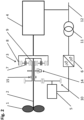
- Fig.1 shows the principle of a differential system not according to the invention for a drive train using the example of a pump.
- the working machine 1 is the rotor of a pump, which is driven by a drive machine 4 via a drive shaft 2 and a differential gear 3.
- the drive machine 4 is preferably a medium-voltage three-phase machine, which is connected to a network 12, which in the example shown is a medium-voltage network due to a medium-voltage three-phase machine.
- the selected voltage level depends on the application and in particular the performance level of the drive machine 4 and can have any desired voltage level without affecting the basic function of the system according to the invention.
- a design-specific operating speed range results according to the number of pole pairs of the drive machine 4.
- the operating speed range is the speed range in which the drive machine 4 can deliver a defined or desired or required torque or, in the case of an electric drive machine, can be synchronized with the network 12.
- a planet carrier 7 is connected to the drive shaft 2, a drive machine 4 to a ring gear 8 and a sun gear 9 of the differential gear 3 to the differential drive 5.
- the core of the differential system in this embodiment is thus a simple planetary gear stage with three inputs and outputs, with one output being connected to the drive shaft 2 of the working machine 1, a first drive to the drive machine 4 and a second drive to the differential drive 5.
- an adaptation gear 10 is implemented between the sun gear 9 and the differential drive 5.
- the adaptation gear 10 can also be multi-stage or designed as a toothed belt or chain drive.
- the adaptation gear 10 can also be used to implement an axis offset for the differential drive 5, which enables a simple design of the differential drive 5 due to the coaxial arrangement of the working machine 1 and the drive machine 4.
- a motor brake 13 is connected to the differential drive 5, which brakes the differential drive 5 when required.
- the differential drive 5 is electrically connected to the network 12 by means of a preferably low-voltage frequency converter, consisting of a motor-side inverter 6a and a network-side inverter 6b, and a transformer 11.
- the transformer compensates for any existing voltage differences between the network 12 and the network-side inverter 6b and can be omitted if the voltage between the drive machine 4, the network-side inverter 6b and the network 12 is the same.
- the inverters 6a and 6b are connected by a DC intermediate circuit and can be spatially separated if required, with the motor-side inverter 6a preferably being positioned as close as possible to the differential drive 5.
- the main advantage of this concept is that the drive machine 4 can be connected directly to a network 12, i.e. without complex power electronics.
- the balance between variable rotor speed and fixed speed of the network-connected drive machine 4 is achieved by the variable-speed differential drive 5.
- Torque Differential drive Torque Drive shaft * y/x , where the size factor y/x is a measure of the gear ratios in the differential gear 3 and in the adaptation gear 10.
- the power of the differential drive 5 is essentially proportional to the product of the percentage deviation of the pump speed from its base speed x drive shaft power. Accordingly, a large speed range basically requires a correspondingly large dimensioning of the differential drive 5. This is also the reason why differential systems are particularly well suited for small speed ranges, although in principle any speed range can be implemented.
- a differential drive 5 for a pump as a working machine 1 has an output of around 15% of the total system output. This in turn means that low speeds cannot be achieved on the working machine 1 with the differential system. If the working machine 1 has to be brought from zero speed with high torque into its working speed range (this is the speed range in which the working machine 1 essentially works), this can only be achieved by braking the differential drive 5 (either electrically or by means of the engine brake 13) and connecting the driving machine 4 to the mains. The working machine 4 in turn can only generate the nominal torque from a standstill with difficulty, or it draws up to 7 times the nominal current in order to accelerate to approximately synchronous speed.
- the starting current can be reduced, but this also reduces the achievable starting torque.
- An improvement can be achieved, for example, by bringing the differential drive 5 to its maximum possible operating speed at the beginning of the start-up. Due to external loads, the working machine 1 remains in a low speed range during this time. This brings the drive machine 4 to a speed which is inevitably set depending on the speed of the working machine 1 on the one hand and the gear ratio of the differential gear 3 and any existing adaptation gear 10 on the other.
- the differential drive 5 is then controlled so that its speed remains within its control speed range, while the drive machine 4 is connected to the network 12 with or without a so-called star/delta connection.
- the speed control or braking of the differential drive 5 is preferably carried out electrically by the inverter 6a, 6b, or by means of the motor brake 13.
- the engine brake 13 can also be used to protect the differential drive 5 from overspeeds if, for example, the drive machine 4 fails and the working machine 1 stops or rotates in the opposite direction.
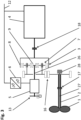
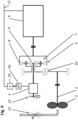
- Fig.2 shows another embodiment of a differential system.
- the drive train shown here also has Fig.1 a working machine 1, a drive shaft 2, a differential gear 3, a drive machine 4 and a differential drive 5, which is connected to the network 12 by means of a frequency converter 6 (consisting of motor-side and network-side inverters - shown here as a simplified unit) and a transformer 11.
- the differential drive 5 is connected to the differential gear 3 by means of an adaptation gear 10.
- a clutch is provided between the adaptation gear 10 and the differential gear 3. 15 implemented.
- a synchronization brake 14 acts on the sun gear 9 and thus on the entire drive train.
- the differential drive 5 and the adaptation gear 10 are decoupled from the rest of the drive train by the clutch 15 in a first step. If the drive machine 4 is now started up and connected to the network, the sun gear 9 rotates freely and no significant torque can build up in the entire drive train. In this case, too, the working machine 1 remains in a low speed range and the drive machine 4 can be synchronized with the network 12 without any significant external counter-torque.
- either a star/delta connection can be implemented or the drive machine 4 can be brought to (approximately) synchronous speed by an auxiliary device - e.g. a small variable speed drive - and then synchronized with the network 12.
- an auxiliary device e.g. a small variable speed drive - and then synchronized with the network 12.
- the clutch 15 closed - as already mentioned Fig.1 described - the drive machine 4 can be brought up to speed with the differential drive 5. In this case, the drive machine 4 cannot be accelerated to its synchronous speed, but at least the resulting starting current is smaller. The clutch 15 is then opened again.
- the control speed range is the speed range in which the differential drive 5 works in order to be able to realize the working speed range of the working machine 1.
- the control speed range is determined primarily by the voltage, current and speed limits specified by the manufacturer.
- the differential drive 5 cannot be connected to the mains 12.
- the synchronization brake 14 is used to decelerate the second drive of the differential gear 3 connected to the sun gear 9 to a speed that is in the control speed range of the differential drive 5.
- the part of the clutch 15 on the differential drive side (preferably by means of the differential drive 5) is preferably synchronized with the speed of the second drive of the differential gear 3 and then the clutch 15 is closed.
- the clutch 15 is preferably a positive-locking claw clutch or a non-positive multi-disk clutch.
- One advantage of the non-positive multi-disk clutch is that, if designed for this purpose, no synchronization of the two clutch halves is necessary.
- the multiple nominal torque can be realized as a starting torque from zero speed, since the typical breakdown moment of a three-phase machine is approximately 2 to 3 times its nominal torque.
- this starting method can also be used with internal combustion engines, for example, which is sometimes necessary because these can only generate a torque in the partial speed range that is significantly lower than their nominal torque.
- the synchronization brake 14 can therefore also basically take over the function of the Fig.1 shown engine brake 13.
- any type of brake can be used.
- retarders are particularly suitable here.
- Hydrodynamic retarders usually work with oil or water, which is fed into a converter housing when required.
- the converter housing consists of two rotationally symmetrical and opposing impellers, and before that a rotor that is connected to the drive train of the system, and a fixed stator.
- the rotor accelerates the supplied oil and the centrifugal force pushes it outwards.
- the shape of the rotor blades directs the oil into the stator, which induces a braking torque in the rotor and then brakes the entire drive train.
- electrodynamic retarder electric brake
- an eddy current brake two steel disks (rotors) that are not magnetized are connected to the drive train. In between is the stator with electrical coils. When current is supplied by activating the retarder, magnetic fields are generated which are closed by the rotors. The opposing magnetic fields then produce the braking effect. The heat generated is released again, for example, through internally ventilated rotor disks.
- a major advantage of a retarder as a service brake is its freedom from wear and good controllability.
- the system can also be used to operate the drive machine 4 in phase shift mode. This means that the drive machine 4 can supply or draw reactive power into or from the network 12 without the driven machine 1 being operated. This applies in particular to energy generation plants.
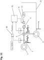
- Fig.3 shows a further embodiment of a differential system with a gear pre-stage 16.
- This gear pre-stage 16 allows the speed range for the drive shaft 2 or for the working machine 1 to be adjusted according to the gear ratio of the gear pre-stage 16.
- the use of a gear pre-stage 16 is then necessary or advantageous if the speed level resulting from the technical parameters of, for example, a cost-effective drive machine 4 and an efficient differential system does not correspond to the required working speed range of a working machine 1.
- a resulting advantage is that, if the gear pre-stage 16 is a spur gear stage as shown, the differential drive 5 can be operated without an adaptation gear 10 according to Fig.1 and 2 can be positioned coaxially to the drive machine 4 on the side of the differential gear 3 facing away from the drive machine.
- stepped planets instead of simple planets.
- These stepped planets each consist of two rotationally fixed gears with different diameters and preferably different tooth geometry.
- the ring gear 8 is then in mesh with the smaller diameter gear of the stepped planet, and the sun gear 9 with the second gear of the stepped planet.
- the connecting shaft 26 between the differential gear 3 and the differential drive 5 is preferably an electrically non-conductive fiber composite shaft. If the connecting shaft 26 is an electrically conductive shaft, then an insulating element should preferably be installed between the differential gear 3 (or, if present, the adaptation gear 10) and the differential drive 5 in order to keep unwanted electrical currents away from the differential gear 3.
- the differential system therefore consists of the smallest possible number of components and also has an optimal overall efficiency.
- the engine brake 13 also fulfils the function of the synchronization brake 14 from Fig.2 .
- Disadvantage of this embodiment compared to that according to Fig.2 is that the differential drive 5 must be designed for a higher speed for the starting process, whereby the differential drive 5 is preferably disconnected from the mains at speeds above the control speed range. This means that speeds outside the control speed range only have to be tolerated mechanically.
- the transmission ratio of the differential gear 3 must be higher than for the solution according to Fig.2 , because the adjustment gear 10 is missing here. In principle, however, the variant acc.
- Fig.3 the additional use of an adaptation gear 10 is possible, whereby the gear ratio of the differential gear 3 can be reduced.
- a clutch 15 and a synchronization brake 14 can also be implemented between the second drive of the differential gear 3 or sun gear 9 and the differential drive 5.
- a further advantage of this embodiment with gear pre-stage 16 is that a coaxial hollow shaft 27 to the working machine 1 can be implemented in a simple manner.
- the rotating working machine 1 can be supplied electrically or hydraulically in a simple manner using this hollow shaft 27.
- a rotary transmission 28 is preferably applied to the side of the gear pre-stage facing away from the working machine.
- a mechanical rod can also be guided in the passage 27 and thus the blades of a pump rotor, for example, can be mechanically adjusted by translatory or rotary movement.
- the drive shaft 2 and the drive motor 4 are preferably connected by means of a coupling 17, 18.
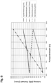
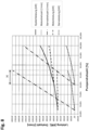
- Fig.4 shows the speed and performance parameters of a differential system not according to the invention, for example for a pump.
- the illustration shows performance and speed values for a pump as working machine 1, a drive machine 4 and a differential drive 5, each plotted against the speed values of the drive shaft 2 ("pump speed").
- the drive machine 4 is connected to the network 12 and thus its speed (“motor speed") is constant - in the example shown, approximately 1,500 rpm for a four-pole three-phase machine in a 50 Hz network.
- the working speed range for the drive shaft 2 goes from 68% to 100%, with 100% being the selected nominal or maximum point.
- the speed of the differential drive 5 (“servo speed") goes from -2,000 rpm to 1,500 rpm.
- the differential drive 5 is operated as a generator (-) and as a motor (+). Since the maximum required power of the differential drive 5 in the generator (-) range (approx. 110 kW) is lower than that in the motor (+) range (approx. 160 kW), the differential drive 5 can be operated in the generator (-) range in the so-called field weakening range, which means that a higher speed - but with reduced torque - can be achieved for the differential drive 5. This makes it easy to expand the speed range for the working machine 1.
- Another way to extend the speed range for the working machine 1 is to use the so-called 87Hz characteristic curve for operating the frequency converter 6.
- the principle is as follows: Motors can typically be operated in star (400V) or delta (230V). If you operate a motor as usual with 400V in star connection, you reach the nominal point at 50 Hz. This characteristic curve is set in the frequency converter. You can also operate a motor with 400V in delta connection and parameterize the frequency converter so that it reaches 50Hz at 230V. This means that the frequency converter only reaches its nominal voltage (400V) at 87Hz ( ⁇ 3 x 50Hz). Since the motor torque is constant up to the nominal point, you can achieve a higher Power. However, it should be noted that the delta connection has a ⁇ 3 higher current than the star connection.
- the frequency converter must be larger.
- the higher frequency also results in higher losses in the motor, for which the motor must be thermally designed.
- the 87 Hz characteristic curve achieves a correspondingly ( ⁇ 3) larger speed range with - in contrast to field weakening - no reduction in torque.
- the point "T” in Fig.4 marks the so-called "base speed” of the drive shaft 2, at which the speed of the differential drive 5 is zero. Ideally, this point “T” is placed in a working range in which the system is operated for large periods of time. At this operating point, the engine brake 13 can be activated, which means that the differential drive 5 does not have to be operated and the associated losses and wear are subsequently avoided.
- the drive In the motor (+) area of the characteristic map, the drive is driven in parallel by the drive machine 4 and the differential drive 5. The sum of both powers is the drive power for the drive shaft 2 ("system power”) - minus any system losses that occur.
- the drive machine 4 In the generator (-) area, the drive machine 4 must compensate for the power of the differential drive 5 ("servo power"), whereby the total system power (“system power”) is the drive power of the drive machine 4 (“motor power”) minus the power of the differential drive 5.
- system power the total system power
- motor power the drive power of the drive machine 4
- the motor (+) area is better in terms of efficiency.
- probability the example frequency distribution of the load distribution in continuous operation of the system, which shows a large part of the operating time in the motor (+) range.
- operation at lower pump speeds is also necessary, whereby the proportionate residence time decreases sharply as the pump speed decreases.
- pump speed the pump speed
- base speed the base speed
- the required size of the drive machine 4 can be reduced by the size of the differential drive 5 compared to a drive according to the state of the art by driving the drive machine 4 and the differential drive 5 in parallel.
- the gear ratio of the differential drive can be set to 1. This makes it possible to accelerate the entire drive train to the synchronous speed of the drive machine 4 with the differential drive 5 and then synchronize this with the network.
- the differential drive 5 can then be switched off as desired and the drive machine 4 drives the work machine 1 alone at synchronous speed.
- the differential drive 5 can drive the work machine 1 parallel to the drive machine 4, which makes it possible to achieve a higher overall drive train power.
- the differential lock and the engine brake 13 two stationary operating points of the drive train can be achieved.
- the differential drive is designed to be so low-power that only the drive machine 4 is synchronized with the network 12 or the differential lock. Alternatively, however, this can also be achieved by optionally driving the output or the first drive of the differential gear 3.
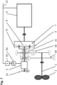
- Fig.5 shows another embodiment of a differential system with a simplified differential drive.
- the grid-side inverter 6b is replaced by a simple rectifier 19. This usually has a higher efficiency than an inverter 6b and is also much more robust and cost-effective.
- the only restriction caused by the use of a rectifier 19 is that the differential drive 5 can only be operated as a motor (+).
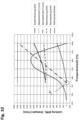
- Fig.6 shows the Fig.5 resulting speed and power parameters at the same working speed range for the drive shaft 2 as in Fig.4 (68%-100%). Due to the fact that the differential drive 5 is only operated in the motor (+) range, the maximum power flow via the differential drive 5 is significantly greater than in the example shown above. At the nominal point, the required power of the differential drive 5 ("servo power") reaches around 500kW, which is 50% of the total drive power (“system power"). This means that the frequency converter 6a, 19 must also be dimensioned accordingly.
- the advantage of this variant is that the transmission ratio of the differential gear 3 is significantly lower than for the variant according to Fig.3 and thus the maximum achievable speed of the differential drive 5 when starting the system is lower.
- Fig.7 shows a further embodiment of a differential system with a gear shift stage.
- the gear pre-stage 16 is expanded by a further gear pre-stage 20, with a different gear ratio than the gear pre-stage 16.
- the switching device 21 one can choose between the two gear pre-stages and thus obtains an adjustable gear 16, 20, 21, which can realize two speed ranges for the drive shaft 2.
- several shift stages can also be implemented.
- Fig.8 shows the Fig.7 resulting speed and power parameters.
- the representation contains two maps - each of them similar to Fig.6 , but with a smaller working speed range for the working machine 1. Due to the two-stage adjustment gear 16, 20, 21, these characteristic maps are offset from each other, which means that with the same overall working speed range for the pump ("pump speed" 68%-100%) a Fig.6 comparable smaller size is required for the differential drive 5.
- the differential drive 5 can be operated in the field weakening range, since the torque required for the differential system is generally smaller than its nominal torque.
- the working speed range in the map with the lower system power is larger than that for the second map.
- the two maps preferably overlap in the hysteresis range "H" in order to avoid frequent switching between the maps.
- the hysteresis range "H” is at the expense of an even smaller differential system in terms of power and, if no overlap of the two maps is required, can also be smaller or even eliminated altogether.
- Fig.9 shows an embodiment of a differential system according to the invention with a reduced speed range.
- the drive train is constructed in the same way as in Fig.5 shown.
- a throttle 22 is integrated in the power system 29 of the working machine 1. This allows the quantity delivered by the working machine 1 to be throttled without reducing the speed of the working machine 1.
- This throttle 22 is usually used in drives that do not have a variable speed in order to regulate/control the quantity delivered.
- the throttle 22 can have a wide variety of designs, with a simple flap being a common variant.
- the variant acc. Fig.9 the additional use of an adaptation gear 10 is possible.
- a clutch 15 and a synchronization brake 14 can be implemented between the second drive or the sun gear 9 and the differential drive 5.
- the gear pre-stage 16 is not absolutely necessary.
- Fig.10 shows the Fig.9 resulting speed and power parameters.
- the selected operating range of the differential system thus moves into an area with a high operating frequency distribution ("probability").
- probability As soon as the differential drive 5 reaches the base speed (point "T") with decreasing pump speed, it is preferably braked or stopped. A lower delivery rate required for operational reasons is achieved by activating (regulating/controlling) the throttle 22.
- the speeds of the differential system remain essentially constant.
- Fig. 11 a control system for damping drive train vibrations is shown.
- the torque on the differential drive 5 is proportional to the torque in the entire drive train, which makes torque regulation/control or drive train damping possible through the differential drive 5.
- Drive train damping is understood here to mean the targeted regulation of rotary drive train vibrations (working machine, drive shaft 2, differential gear 3, drive machine 4 and differential drive 5), which can occur constantly or transiently and lead to undesirable loads in the entire drive train or in parts. This is achieved by modulating the torque and/or the speed of the differential drive 5 with vibrations of the same frequency.
- Such undesirable drive train vibrations or transient drive train loads can arise either from external loads on the working machine 1, in the drive shaft 2, the differential gear 3 and the differential drive 5 itself or from the drive machine 4 and are typically visible in the speed or torque behavior of the drive train.
- these can be recorded by speed and/or vibration measurements in the drive train or by current measurements on the drive machine 4 and/or on the differential drive 5.
- Direct recording of torques is also possible, but is usually only possible with great effort. The type of recording ultimately always depends on where in the drive train the damping is to take place and whether couplings can be used.
- drive train vibrations are caused, for example, by typical operating behavior on the working machine 1, and their effect on the drive machine 4 is to be compensated, they can be reduced or eliminated by impressing antiphase torque vibrations on the differential drive 5.
- This is the case, for example, with compressors, where one rotation of the piston rod leads to design-specific vibration excitations that correlate strongly with the piston position. Since the respective vibration excitation always occurs at the same piston position, it is sufficient to know the circumferential position or rotational position, e.g. by measurement, in order to be able to compensate for it. Knowing this vibration excitation allows the selective compensation of individual or multiple vibrations at the same time. This is preferably achieved by detecting the position of the piston rod or by one of the methods listed above.
- the necessary synchronous and antiphase torque/speed adjustment is realized by conventional signal processing methods, preferably with oscillators and notch filter algorithms, which simulate the measured vibration excitation with the correct frequencies and evaluate. Integrated into a negative feedback system, the necessary amplitudes and phase positions for the vibrations generated for compensation are automatically set, which are then used to control the actuator on the differential drive 5.
- a constant speed n 4 of the drive machine to be achieved and the speed n 2 of the drive shaft 2 are fed to a comparison circuit 30.
- a control device 31 controls the differential drive 5 on the basis of the desired speed n 5 desired determined therefrom and the actual speed n 5 of the input shaft of the differential drive 5 via the frequency converter 6 in such a way that vibrations of the drive machine 4 are dampened as well as possible or desired.
- the values given with reference to Fig. 11 The drive train damping described can also be used independently of all other embodiments described above.
Landscapes
- Engineering & Computer Science (AREA)
- General Engineering & Computer Science (AREA)
- Mechanical Engineering (AREA)
- Life Sciences & Earth Sciences (AREA)
- Sustainable Development (AREA)
- Sustainable Energy (AREA)
- Chemical & Material Sciences (AREA)
- Combustion & Propulsion (AREA)
- Power Engineering (AREA)
- Physics & Mathematics (AREA)
- General Physics & Mathematics (AREA)
- Automation & Control Theory (AREA)
- Control Of Vehicle Engines Or Engines For Specific Uses (AREA)
- Structure Of Transmissions (AREA)
- Electric Propulsion And Braking For Vehicles (AREA)
- Connection Of Motors, Electrical Generators, Mechanical Devices, And The Like (AREA)
Description
- Die Erfindung betrifft ein Verfahren zum Betreiben eines Triebstranges mit einer Antriebswelle, einer mit einem Stromnetz verbundenen, motorisch und generatorisch betreibbaren, elektrischen Antriebsmaschine und mit einem Differenzialgetriebemit drei An- bzw. Abtrieben, wobei ein Abtrieb mit der Antriebswelle ein Antrieb mit der Antriebsmaschine und ein zweiter Antrieb mit einem Differenzialantrieb verbunden ist.
- Die Erfindung betrifft des Weiteren einen Triebstrang mit einer Antriebswelle, einer mit einem Stromnetz verbundenen, motorisch und generatorisch betreibbaren, elektrischen Antriebsmaschine und mit einem Differenzialgetriebe mit drei An- bzw. Abtrieben, wobei ein Abtrieb mit der Antriebswelle, ein Antrieb mit der Antriebsmaschine und ein zweiter Antrieb mit einem elektrischen Differenzialantrieb verbunden ist
-
WO 2010/101467 A (sieheFig. 3 ) offenbart einen Triebstrang für ein Fahrzeug, mit einem Differenzial und zwei elektrischen Maschinen, die wahlweise motorisch oder generatorisch betrieben werden können. - Ein allgemeines Problem von Arbeitsmaschinen, wie Fördereinrichtungen, z.B. Pumpen, Kompressoren und Ventilatoren, oder wie Mühlen, Brecher, Fahrzeuge usw., ist ein effizienter drehzahlvariabler Betrieb. Im Weiteren werden elektrische Maschinen als Beispiel für Antriebsmaschinen herangezogen, das Prinzip gilt aber für alle möglichen Arten von Antriebsmaschinen so wie z.B. für Verbrennungskraftmaschinen. Die am häufigsten verwendeten elektrischen Antriebe sind heutzutage Drehstrommaschinen wie z.B. Asynchronmotoren und Synchronmotoren.
- Der Erfindung liegt die Aufgabe zu Grunde, ein Verfahren und eine Vorrichtung der eingangs genannten Art anzugeben, bei denen bei einfachem Aufbau eine Änderung der Fördermenge der Fördereinrichtung möglich ist.
- Gelöst wird diese Aufgabe bei einem Verfahren mit den Merkmalen des Anspruchs 1.
- Gelöst wird diese Aufgabe des Weiteren mit einem Triebstrang mit den Merkmalen des Anspruchs 7.
- Der Kern eines Differenzialsystems ist ein Differenzialgetriebe, das in einer einfachen Ausführung eine einfache Planetengetriebestufe mit drei An- bzw. Abtrieben ist, wobei ein Abtrieb mit der Antriebswelle einer Arbeitsmaschine, ein erster Antrieb mit der Antriebsmaschine und ein zweiter Antrieb mit einem Differenzialantrieb verbunden ist. Damit kann die Arbeitsmaschine bei konstanter Drehzahl der Antriebsmaschine drehzahlvariabel betrieben werden, indem der Differenzialantrieb die Drehzahldifferenz ausgleicht.
- Mit dem Differentialantrieb kann die von der Arbeitsmaschine geförderte Menge erhöht werden, indem die konstante Leistung der Antriebsmaschine durch die variable Leistung des Differenzialantriebs erhöht wird.
- Wenn der üblicherweise für einen elektrischen Differenzialantrieb verwendete Wechselrichter durch einen Gleichrichter ersetzt wird, ist dies vorteilhaft, da dieser meist einen höheren Wirkungsgrad als ein Wechselrichter aufweist und ist auch wesentlich robuster und kostengünstiger ist.
- Die Erfindung kann beispielsweise bei Speicherkraftwerken Verwendung finden.
- Nachfolgend werden bevorzugte Ausführungsformen der Erfindung mit Bezug auf die angeschlossenen Zeichnungen erläutert. Es zeigt:
- Fig. 1
- das Prinzip eines nicht erfindungsgemäßen Differenzialsystems für einen Antrieb einer Pumpe,
- Fig. 2
- eine weitere Ausführungsform eines Differenzialsystems,
- Fig. 3
- eine weitere Ausführungsform eines Differenzialsystems mit einer Getriebevorstufe,
- Fig. 4
- die Drehzahl- und Leistungsparameter eines nicht erfindungsgemäßen Differenzialsystems einer Pumpe,
- Fig. 5
- eine weitere Ausführungsform eines Differenzialsystems mit einem vereinfachten Differenzialantrieb,
- Fig. 6
- die sich aus
Fig. 5 ergebenden Drehzahl- und Leistungsparameter, - Fig. 7
- eine weitere Ausführungsform eines Differenzialsystems mit einer Getriebeschaltstufe,
- Fig. 8
- die sich aus
Fig. 7 ergebenden Drehzahl- und Leistungsparameter, - Fig. 9
- eine weitere Ausführungsform eines Differenzialsystems mit reduziertem Drehzahlbereich,
- Fig. 10
- die sich aus
Fig. 9 ergebenden Drehzahl- und Leistungsparameter, und - Fig. 11
- ein Regelsystem zum Dämpfen von Triebstrangschwingungen.
- Trotz hoher elektrischer Leistungsaufnahme sind Drehstrommaschinen bei Stillstand nicht im Stande diese Leistung vollständig mechanisch abzugeben, was sich in hohen Verlusten und einem geringen Anfahrmoment wiederspiegelt. Gleichzeitig entspricht die Stromaufnahme einer Drehstrommaschine beim Start von Drehzahl Null aus typischerweise dem ca. 7-fachen Nennstrom, was beim Anfahren eine entsprechend hohe elektrische Last für das Netz verursacht.
- Es muss daher eine Drehstrommaschine entsprechend groß ausgelegt werden, damit sie vom Stillstand an ein dem Nenndrehmoment entsprechendes Antriebsmoment liefern kann, und ist deswegen oft überdimensioniert. Elektrische Maschinen werden daher auch aus diesem Grund, anstatt direkt an ein Netz angeschlossen zu werden, häufig in Kombination mit einem Frequenzumrichter als drehzahlvariabler Antrieb ausgeführt. Damit kann man zwar ein Anfahren mit hohem Drehmoment von Drehzahl Null realisieren ohne das Netz zu belasten, die Lösung ist jedoch teuer und mit wesentlichen Wirkungsgradeinbußen verbunden. Eine im Vergleich dazu kostengünstigere und auch bezüglich Wirkungsgrad bessere Alternative ist der Einsatz von Differenzialsystemen - beispielsweise gemäß
AT 507 394 - Um dies zu realisieren gibt es verschiedene Möglichkeiten. Gemäß Deutschem Gebrauchsmuster Nr.
20 2012 101 708.3 beispielsweise kann man das Übersetzungsverhältnis des Differenzialgetriebes auf 1 festlegen. Auf dieser Basis kann man mit dem Differenzialantrieb den kompletten Triebstrang antreiben bzw. die Antriebsmaschine auf Synchrondrehzahl bringen und diese in weiterer Folge mit dem Netz synchronisieren. - Nachteil dieser Lösung ist, dass der Differenzialantrieb bzw. dessen Frequenzumrichter wesentlich kleiner dimensioniert ist als die Antriebsmaschine und daher auch nur ein entsprechend kleines Drehmoment liefern kann.
- Um eine Antriebsmaschine unter Last entweder mit dem Netz zu synchronisieren (wie z.B. direkt an das Netz gekoppelte elektrische Maschinen) oder in einen Drehzahlbereich mit hohem zur Verfügung stehenden Drehmoment (wie z.B. bei Verbrennungskraftmaschinen) beschleunigen und zusätzlich die Arbeitsmaschine mit maximalem bzw. Auslegungs-Drehmoment des Triebstranges von Drehzahl Null weg anfahren zu können und vorzugsweise auf Synchrondrehzahl zu bringen, kann das Anlaufen z.B. wie folgt in 3 Phasen stattfinden:
- Phase 1: Die Antriebsmaschine wird vorzugsweise mit sogenannter Stern/Dreieck-Schaltung ans Netz geschaltet oder alternativ (in einer besonders netzschonenden Methode) zuerst mit einer zusätzlichen Einrichtung auf (zumindest näherungsweise) Synchrondrehzahl gebracht und dann mit dem Netz synchronisiert. Im Falle einer Verbrennungskraftmaschine wird diese einfach gestartet und anschließend hochgefahren. Dabei bleibt die Antriebsmaschine während des Anfahrens, abgesehen von den zu überwindenden massenträgheitsmomentbedingten Reaktionskräften vom zweiten Antrieb des Differenzialgetriebes, weitgehend frei von äußeren mechanischen Lasten. Im Umkehrschluss bedeutet dies, dass, bis die Antriebsmaschine ihre Nenndrehzahl erreicht hat, auf die Antriebswelle der Arbeitsmaschine ein entsprechend kleines antreibendes Drehmoment wirkt.
- Phase 2: Da jetzt das volle Drehmoment der Antriebsmaschine zur Verfügung steht, beginnt in der zweiten Phase das eigentliche Beschleunigen und Anfahren der Arbeitsmaschine unter Last, indem der zweite Antrieb der Differenzialgetriebestufe mittels einer Synchronisationsbremse verzögert wird.
- Phase 3: Sobald die Antriebswelle des zweiten Antriebs des Differenzialsystems im Regeldrehzahlbereich des Differenzialantriebs ist, übernimmt dieser die Drehzahlregelung des Triebstrangs und die Synchronisationsbremse wird gelöst.
-
Fig. 1 zeigt das Prinzip eines nicht erfindungsgemäßen Differenzialsystems für einen Triebstrang am Beispiel einer Pumpe. Dabei ist die Arbeitsmaschine 1 der Rotor einer Pumpe, welcher über eine Antriebswelle 2 und ein Differenzialgetriebe 3 von einer Antriebsmaschine 4 angetrieben wird. Die Antriebsmaschine 4 ist vorzugsweise eine Mittelspannungs-Drehstrommaschine, welche an ein Netz 12, welches im gezeigten Beispiel aufgrund einer Mittelspannungs-Drehstrommaschine ein Mittelspannungsnetz ist, angeschlossen wird. Das gewählte Spannungsniveau hängt jedoch vom Einsatzfall und v.a. dem Leistungsniveau der Antriebsmaschine 4 ab und kann ohne Einfluss auf die Grundfunktion des erfindungsgemäßen Systems, jedes gewünschte Spannungsniveau haben. Entsprechend der Polpaarzahl der Antriebsmaschine 4 ergibt sich ein bauartspezifischer Betriebsdrehzahlbereich. Der Betriebsdrehzahlbereich ist dabei jener Drehzahlbereich, in dem die Antriebsmaschine 4 ein definiertes bzw. gewünschtes bzw. erforderliches Drehmoment liefern bzw. im Falle einer elektrischen Antriebsmaschine mit dem Netz 12 synchronisiert werden kann. Ein Planetenträger 7 ist mit der Antriebswelle 2 verbunden, eine Antriebsmaschine 4 mit einem Hohlrad 8 und ein Sonnenrad 9 des Differenzialgetriebes 3 mit dem Differenzialantrieb 5. Der Kern des Differenzialsystems ist in dieser Ausführungsform somit eine einfache Planetengetriebestufe mit drei An- bzw. Abtrieben, wobei ein Abtrieb mit der Antriebswelle 2 der Arbeitsmaschine 1, ein erster Antrieb mit der Antriebsmaschine 4 und ein zweiter Antrieb mit dem Differenzialantrieb 5 verbunden ist. Um den Drehzahlbereich des Differenzialantriebs 5 optimal anpassen zu können, wird ein Anpassungsgetriebe 10 zwischen dem Sonnenrad 9 und dem Differenzialantrieb 5 implementiert. - Alternativ zur gezeigten Stirnradstufe kann das Anpassungsgetriebe 10 beispielsweise auch mehrstufig sein bzw. als Zahnriemen oder Kettentrieb ausgeführt werden. Mit dem Anpassungsgetriebe 10 kann man darüber hinaus einen Achsversatz für den Differenzialantrieb 5 realisieren, der aufgrund der koaxialen Anordnung der Arbeitsmaschine 1 und der Antriebsmaschine 4 eine einfache Ausführung des Differenzialantriebes 5 ermöglicht. Mit dem Differenzialantrieb 5 ist eine Motorbremse 13 verbunden, welche den Differenzialantrieb 5 bei Bedarf bremst. Elektrisch ist der Differenzialantrieb 5 mittels eines vorzugsweise Niederspannungs-Frequenzumrichters, bestehend aus einem motorseitigen Wechselrichter 6a und einem netzseitigen Wechselrichter 6b, und einem Transformator 11 an das Netz 12 angebunden. Der Transformator gleicht allfällige vorhandene Spannungsdifferenzen zwischen dem Netz 12 und dem netzseitigen Wechselrichter 6b aus und kann bei Spannungsgleichheit zwischen der Antriebsmaschine 4, dem netzseitigen Wechselrichter 6b und dem Netz 12 entfallen. Die Wechselrichter 6a und 6b sind durch einen Gleichstromzwischenkreis verbunden und können bei Bedarf örtlich getrennt sein, wobei vorzugsweise der motorseitige Wechselrichter 6a so nah wie möglich beim Differenzialantrieb 5 positioniert ist. Wesentlicher Vorteil dieses Konzeptes ist, dass die Antriebsmaschine 4 direkt, das heißt ohne aufwändige Leistungselektronik, an ein Netz 12 angebunden werden kann. Der Ausgleich zwischen variabler Rotordrehzahl und fixer Drehzahl der netzgebundenen Antriebsmaschine 4 wird durch den drehzahlvariablen Differenzialantrieb 5 realisiert.
- Die Drehmomentgleichung für das Differenzialsystem lautet:

- Ein Differenzialantrieb 5 für eine Pumpe als Arbeitsmaschine 1 hat beispielsweise eine Leistung von rund 15% der System-Gesamtleistung. Das wiederum bedeutet, dass mit dem Differenzialsystem keine niedrigen Drehzahlen an der Arbeitsmaschine 1 realisiert werden können. Muss die Arbeitsmaschine 1 von Drehzahl Null mit hohem Drehmoment in ihren Arbeitsdrehzahlbereich (dies ist der Drehzahlbereich, in dem die Arbeitsmaschine 1 im Wesentlichen arbeitet) gebracht werden, so kann dies nur realisiert werden, indem der Differenzialantrieb 5 eingebremst (entweder elektrisch oder mittels Motorbremse 13) und die Antriebsmaschine 4 an das Netz geschaltet wird. Die Arbeitsmaschine 4 wiederum kann aus dem Stand das Nenndrehmoment nur schwer aufbringen, bzw. zieht sie einen bis zu 7-fachen Nennstrom, um annähernd auf Synchrondrehzahl zu beschleunigen.
- Durch Einsatz einer sogenannten Stern/Dreieck-Schaltung kann man zwar den Anfahrstrom reduzieren, reduziert damit jedoch auch das realisierbare Anfahrmoment.
- Eine Verbesserung erzielt man z. B., indem der Differenzialantrieb 5 zu Beginn des Anfahrens auf seine maximal mögliche Betriebsdrehzahl gebracht wird. Aufgrund äußerer Lasten verbleibt währenddessen die Arbeitsmaschine 1 in einem Bereich kleiner Drehzahl. Dadurch wird die Antriebsmaschine 4 auf eine Drehzahl gebracht, welche sich abhängig von der Drehzahl der Arbeitsmaschine 1 einerseits und dem Übersetzungsverhältnis des Differenzialgetriebes 3 und eines evtl. vorhandenen Anpassungsgetriebes 10 andererseits zwangsläufig einstellt. Anschließend wird der Differenzialantrieb 5 so geregelt, dass seine Drehzahl innerhalb seines Regeldrehzahlbereichs bleibt, während die Antriebsmaschine 4 mit oder ohne sogenannte Stern/Dreieck-Schaltung ans Netz 12 geschaltet wird. Die Drehzahlregelung bzw. Bremsung des Differenzialantriebes 5 erfolgt dabei vorzugsweise elektrisch durch den Wechselrichter 6a, 6b, oder mittels Motorbremse 13.
- Die Motorbremse 13 kann auch dazu verwendet werden, den Differenzialantrieb 5 vor Überdrehzahlen zu schützen, wenn z. B. die Antriebsmaschine 4 ausfällt und die Arbeitsmaschine 1 anhält oder in die Gegenrichtung dreht.
-
Fig. 2 zeigt eine weitere Ausführungsform eines Differenzialsystems. Der gezeigte Triebstrang weist auch hier wie inFig. 1 eine Arbeitsmaschine 1, eine Antriebswelle 2, ein Differenzialgetriebe 3, eine Antriebsmaschine 4 und eine Differenzialantrieb 5 auf, welcher mittels eines Frequenzumrichter 6 (bestehend aus motorseitigem und netzseitigen Wechselrichter - hier als Einheit vereinfacht dargestellt) und eines Transformators 11 an das Netz 12 angeschlossen ist. Auch hier wird der Differenzialantrieb 5 mittels eines Anpassungsgetriebes 10 an das Differenzialgetriebe 3 angebunden. Zusätzlich wird jedoch zwischen dem Anpassungsgetriebe 10 und dem Differenzialgetriebe 3 eine Kupplung 15 implementiert. - Eine Synchronisationsbremse 14 wirkt auf das Sonnenrad 9 und damit auf den gesamten Triebstrang. Beim Anfahren werden in einem ersten Schritt der Differenzialantrieb 5 und das Anpassungsgetriebe 10 durch die Kupplung 15 vom Rest des Triebstranges entkoppelt. Wird nun die Antriebsmaschine 4 hochgefahren und mit dem Netz verbunden, so dreht das Sonnenrad 9 frei mit und es kann sich im gesamten Triebstrang kein nennenswertes Drehmoment aufbauen. Somit verbleibt auch in diesem Fall die Arbeitsmaschine 1 in einem Bereich kleiner Drehzahl und die Antriebsmaschine 4 kann ohne nennenswertes äußeres Gegenmoment mit dem Netz 12 synchronisiert werden.
- Um den oben beschriebenen Effekt des hohen Anfahrstromes beim Synchronisieren der Antriebsmaschine 4 zu vermeiden, kann entweder eine Stern/Dreieck-Schaltung implementiert oder die Antriebsmaschine 4 durch eine Hilfseinrichtung - z.B. einen kleinen drehzahlvariablen Antrieb - auf (annähernd) Synchrondrehzahl gebracht und anschließend mit dem Netz 12 synchronisiert werden. Alternativ kann bei geschlossener Kupplung 15 - wie schon zu
Fig. 1 beschrieben - die Antriebsmaschine 4 mit dem Differenzialantrieb 5 auf Drehzahl gebracht werden. Dabei kann die Antriebsmaschine 4 zwar nicht bis zu ihrer Synchrondrehzahl beschleunigt werden, zumindest ist jedoch der sich einstellende Anfahrstrom kleiner. Die Kupplung 15 wird dann wieder geöffnet. - Sobald die Antriebsmaschine 4 über eine gewisse Drehzahl beschleunigt wurde und die Arbeitsmaschine 1 sich währenddessen nur langsam dreht, stellt sich am Sonnenrad 9 eine entsprechend dem Übersetzungsverhältnis des Differenzialgetriebes 3 hohe Drehzahl ein, welche (unter Berücksichtigung des Anpassungsgetriebes 10) über dem erlaubten Regeldrehzahlbereich für den Differenzialantrieb 5 liegt. Der Regeldrehzahlbereich ist der Drehzahlbereich, in dem der Differenzialantrieb 5 arbeitet um den Arbeitsdrehzahlbereich der Arbeitsmaschine 1 realisieren zu können. Der Regeldrehzahlbereich wird dabei v.a. durch die vom Hersteller spezifizierten Spannungs-, Strom- und Drehzahlgrenzen bestimmt. In dieser Phase kann der Differenzialantrieb 5 nicht mit dem Netz 12 verbunden sein. In einem weiteren Schritt wird daher mit der Synchronisationsbremse 14 der mit dem Sonnenrad 9 verbundene zweite Antrieb des Differenzialgetriebes 3 auf eine Drehzahl verzögert, welche im Regeldrehzahlbereich des Differenzialantriebs 5 liegt. In weiterer Folge wird der differenzialantriebseitige Teil der Kupplung 15 (vorzugsweise mittels Differenzialantrieb 5) vorzugsweise mit der Drehzahl des zweiten Antriebs des Differenzialgetriebes 3 synchronisiert und anschließend die Kupplung 15 geschlossen. Die Kupplung 15 ist vorzugsweise eine formschlüssige Klauenkupplung oder eine kraftschlüssige Lamellenkupplung. Ein Vorteil der kraftschlüssigen Lamellenkupplung ist, dass, wenn dafür ausgelegt, keine Synchronisation der beiden Kupplungshälften notwendig ist.
- Durch Betätigung der Synchronisationsbremse 14 wird zwangsläufig die Antriebswelle 2 beschleunigt, wobei das dazu zur Verfügung stehende Drehmoment durch das Minimum aus der auf die Antriebswelle 2 wirkenden Bremskraft der Synchronisationsbremse 14 einerseits und dem Kippmoment der Antriebsmaschine 4 andererseits bestimmt wird. D.h. im Gegensatz zu den Anfahroptionen gemäß Stand der Technik kann hier das mehrfache Nenndrehmoment als Anfahrmoment von Drehzahl Null weg realisiert werden, da das typische Kippmoment einer Drehstrommaschine bei ca. 2 bis 3-fachem ihres Nenndrehmomentes liegt. Grundsätzlich kann diese Anfahrmethode auch bei z.B. Verbrennungskraftmaschinen eingesetzt werden, was mitunter erforderlich ist, weil diese im Teildrehzahlbereich nur ein Drehmoment erzeugen können, welches wesentlich geringer als ihr Nenndrehmoment ist.
- Als Synchronisationsbremse 14 wird beispielweise eine Scheibenbremse (= mechanische Bremse) eingesetzt, womit diese auch als Betriebs- und Sicherheitsbremse für den Differenzialantrieb 5 dienen kann. Damit kann die Synchronisationsbremse 14 grundsätzlich auch die Funktion der in
Fig. 1 dargestellten Motorbremse 13 erfüllen. - Alternativ kann jedoch jede Art von Bremse eingesetzt werden. Insbesondere bieten sich hier sogenannte Retarder an. Hier ist zunächst einmal die Gruppe der hydrodynamischen Retarder (= hydraulische Bremse) zu nennen. Hydrodynamische Retarder arbeiten meist mit Öl oder Wasser, das bei Bedarf in ein Wandlergehäuse geleitet wird. Das Wandlergehäuse besteht aus zwei rotationssymmetrischen und sich gegenüberliegenden Schaufelrädern, und zuvor einem Rotor, der mit dem Triebstrang der Anlage verbunden ist, und einem feststehenden Stator. Der Rotor beschleunigt das zugeführte Öl und die Zentrifugalkraft drückt es nach außen. Durch die Form der Rotorschaufeln wird das Öl in den Stator geleitet, der dadurch ein bremsendes Drehmoment im Rotor induziert und in weiterer Folge dann auch den gesamten Triebstrang bremst. Bei einem elektrodynamischen Retarder (= elektrische Bremse), z.B. einer Wirbelstrombremse, sind z.B. zwei Stahlscheiben (Rotoren), die nicht magnetisiert sind, mit dem Antriebsstrang verbunden. Dazwischen liegt der Stator mit elektrischen Spulen. Wenn durch Aktivierung des Retarders Strom eingesteuert wird, werden Magnetfelder erzeugt, die durch die Rotoren geschlossen werden. Die gegenläufigen Magnetfelder erzeugen dann die Bremswirkung. Die entstandene Wärme wird z.B. durch innenbelüftete Rotorscheiben wieder abgegeben.
- Ein wesentlicher Vorteil eines Retarders als Betriebsbremse ist dessen Verschleißfreiheit und gute Regelbarkeit.
- Das System kann auch dazu verwendet werden, die Antriebsmaschine 4 im Phasenschiebebetrieb zu betreiben. D. h., dass die Antriebsmaschine 4 Blindstrom ins das bzw. aus dem Netz 12 liefern bzw. beziehen kann, ohne dass die Arbeitsmaschine 1 betrieben wird. Dies gilt insbesondere für Energiegewinnungsanlagen.
-
Fig. 3 zeigt eine weitere Ausführungsform eines Differenzialsystems mit einer Getriebevorstufe 16. Durch diese Getriebevorstufe 16 kann der Drehzahlbereich für die Antriebswelle 2 bzw. für die Arbeitsmaschine 1 entsprechend dem Übersetzungsverhältnisses der Getriebevorstufe 16 angepasst werden. Der Einsatz einer Getriebevorstufe 16 ist dann notwendig bzw. von Vorteil, wenn das aufgrund der technischen Parameter einer z.B. kostengünstigen Antriebsmaschine 4 und eines effizienten Differenzialsystems resultierende Drehzahlniveau nicht dem geforderten Arbeitsdrehzahlbereich einer Arbeitsmaschine 1 entspricht. Ein sich dadurch ergebender Vorteil ist, dass, sofern die Getriebevorstufe 16 wie dargestellt eine Stirnradstufe ist, der Differenzialantrieb 5 ohne einem Anpassungsgetriebe 10 gemäßFig. 1 und2 koaxial zur Antriebsmaschine 4 auf der antriebsmaschinenabgewandten Seite des Differenzialgetriebes 3 positioniert werden kann. Um ein dadurch evtl. erforderliches höheres Übersetzungsverhältnis im Differenzialgetriebe 3 zu erreichen, bietet sich an, anstelle einfacher Planeten, sogenannte Stufenplaneten einzusetzen. Diese Stufenplaneten bestehen jeweils aus zwei drehfest verbunden Zahnrädern mit unterschiedlichem Durchmesser und vorzugsweise unterschiedlicher Verzahnungsgeometrie. Das Hohlrad 8 ist dann mit dem im Durchmesser kleineren Zahnrad des Stufenplaneten im Eingriff, und das Sonnenrad 9 mit dem zweiten Zahnrad des Stufenplaneten. Die Verbindungswelle 26 zwischen dem Differenzialgetriebe 3 und dem Differenzialantrieb 5 ist vorzugsweise eine elektrisch nicht leitende Faserverbundwelle. Ist die Verbindungswelle 26 eine elektrisch leitende Welle, dann ist vorzugsweise ein isolierendes Element zwischen dem Differenzialgetriebe 3 (bzw. falls vorhanden der Anpassungsgetriebe 10) und dem Differenzialantrieb 5 einzubauen, um unerwünschte elektrische Ströme vom Differenzialgetriebe 3 fernzuhalten. - Damit besteht das Differenzialsystem aus einer kleinstmöglichen Anzahl von Bauteilen und hat darüber hinaus einen optimalen Gesamtwirkungsgrad. Die Motorbremse 13 erfüllt in der gezeigten Konfiguration auch die Funktion der Synchronisationsbremse 14 aus
Fig. 2 . Nachteil dieser Ausführungsform im Vergleich zu der gemäßFig. 2 ist, dass der Differenzialantrieb 5 für den Anfahrvorgang für eine höhere Drehzahl ausgelegt werden muss, wobei der Differenzialantrieb 5 bei Drehzahlen über dem Regeldrehzahlbereich vorzugsweise vom Netz getrennt ist. Damit müssen Drehzahlen außerhalb des Regeldrehzahlbereiches nur mechanisch ertragen werden. Erschwerend kommt hinzu, dass das Übersetzungsverhältnis des Differenzialgetriebes 3 höher sein muss als für die Lösung gemäßFig. 2 , weil hier das Anpassungsgetriebe 10 fehlt. Grundsätzlich ist jedoch auch für die Variante gem.Fig. 3 der zusätzliche Einsatz eines Anpassungsgetriebes 10 möglich, wodurch das Übersetzungsverhältnis des Differenzialgetriebes 3 kleiner werden kann. Darüber hinaus kann auch eine Kupplung 15 und eine Synchronisationsbremse 14 zwischen dem zweiten Antrieb des Differenzialgetriebes 3 bzw. Sonnenrad 9 und dem Differenzialantrieb 5 implementiert werden. - Ein weiterer Vorteil dieser Ausführungsform mit Getriebevorstufe 16 ist, dass auf einfache Weise eine koaxiale Hohlwelle 27 zur Arbeitsmaschine 1 realisiert werden kann. Mittels dieser Hohlwelle 27 kann die sich drehende Arbeitsmaschine 1 auf einfache Weise elektrisch oder hydraulisch versorgt werden. Dabei wird vorzugsweise eine Drehübertragung 28 zur an der arbeitsmaschinenabgewandten Seite der Getriebevorstufe appliziert. Prinzipiell kann auch ein mechanisches Gestänge in der Durchführung 27 geführt werden und damit durch translatorische oder drehende Bewegung z.B. die Schaufeln eines Pumpenrotors mechanisch verstellt werden.
- Sind das Differenzialsystem und die Getriebevorstufe 16 als sogenannte "standalone"-Variante vorgesehen, so werden die Antriebswelle 2 und die Antriebsmaschine 4 vorzugsweise mittels einer Kupplung 17, 18 angeschlossen.
-
Fig. 4 zeigt die Drehzahl- und Leistungsparameter eines nicht erfindungsgemäßen Differenzialsystems, beispielsweise für eine Pumpe. Die Darstellung zeigt Leistungs- und Drehzahlwerte für eine Pumpe als Arbeitsmaschine 1, eine Antriebsmaschine 4 und einen Differenzialantrieb 5 jeweils aufgetragen über den Drehzahlwerten der Antriebswelle 2 ("Pumpendrehzahl"). Die Antriebsmaschine 4 ist mit dem Netz 12 verbunden und damit ist ihre Drehzahl ("Motordrehzahl") konstant - in dem gezeigten Beispiel ca. 1.500 1/min für eine vierpolige Drehstrommaschine in einem 50 Hz-Netz. Der Arbeitsdrehzahlbereich für die Antriebswelle 2 geht von 68 % bis 100 %, wobei bei 100 % der gewählte Nenn- bzw. Maximalpunkt ist. Entsprechend dem Übersetzungsverhältnis des Differenzialsystems geht die Drehzahl des Differenzialantriebes 5 ("Servodrehzahl") von -2.000 1/min bis 1.500 1/min. Dies bedeutet, dass der Differenzialantrieb 5 generatorisch (-) und motorisch (+) betrieben wird. Da die maximal erforderliche Leistung des Differenzialantriebes 5 im generatorischen (-) Bereich (ca. 110kW) geringer als die im motorischen (+) Bereich (ca. 160kW) ist, kann der Differenzialantrieb 5 im generatorischen (-) Bereich im sogenannten Feldschwächebereich betrieben werden, womit für den Differenzialantrieb 5 eine höhere Drehzahl - jedoch mit reduziertem Drehmoment - realisierbar ist. Damit kann auf einfache Weise der Drehzahlbereich für die Arbeitsmaschine 1 erweitert werden. - Eine weitere Möglichkeit, den Drehzahlbereich für die Arbeitsmaschine 1 zu erweitern, bietet die sogenannte 87Hz-Kennlinie für den Betrieb des Frequenzumrichters 6. Das Prinzip ist dabei folgendes: Motoren kann man typischerweise in Stern (400V) oder Dreieck (230V) betreiben. Betreibt man einen Motor wie üblich mit 400V in Sternschaltung, dann erreicht man bei 50 Hz den Nennpunkt. Diese Kennlinie wird im Frequenzumrichter eingestellt. Man kann einen Motor aber auch mit 400V in Dreieckschaltung betreiben und den Frequenzumrichter so parametrieren, dass er bei 230V die 50Hz erreicht. Dadurch erreicht der Frequenzumrichter seine Nennspannung (400V) erst bei 87Hz (√3 x 50Hz). Da das Motordrehmoment bis zum Nennpunkt konstant ist, erreicht man mit der 87Hz-Kennlinie eine höhere Leistung. Zu beachten ist dabei jedoch, dass man im Vergleich zur Sternschaltung bei der Dreieckschaltung einen um √3 höheren Strom hat. D.h. der Frequenzumrichter muss stärker dimensioniert sein. Darüber hinaus entstehen im Motor durch die höhere Frequenz auch höhere Verluste, für die der Motor thermisch ausgelegt sein muss. Letztendlich erreicht man jedoch mit der 87Hz-Kennlinie einen entsprechend (√3) größeren Drehzahlbereich mit - im Gegensatz zur Feldschwächung - nicht reduziertem Drehmoment.
- Der Punkt "T" in
Fig. 4 markiert die sogenannte "Grunddrehzahl" der Antriebswelle 2, bei der die Drehzahl des Differenzialantriebes 5 gleich Null ist. Idealerweise wird dieser Punkt "T" in einen Arbeitsbereich gelegt, in dem die Anlage über große Zeitanteile betrieben wird. In diesem Betriebspunkt kann die Motorbremse 13 aktiviert werden, womit der Differenzialantrieb 5 nicht betrieben werden muss und in weiterer Folge damit zusammenhängende Verluste und Verschleiß vermieden werden. Im motorischen (+) Bereich des Kennfeldes wird der Antrieb parallel von der Antriebsmaschine 4 und dem Differenzialantrieb 5 angetrieben. Die Summe beider Leistungen ist die Antriebsleistung für die Antriebswelle 2 ("Systemleistung") - abzüglich anfallender Systemverluste. Im generatorischen (-) Bereich muss die Antriebsmaschine 4 die Leistung des Differenzialantriebes 5 ("Servoleistung") kompensieren, wodurch die Systemgesamtleistung ("Systemleistung") die Antriebsleistung der Antriebsmaschine 4 ("Motorleistung") abzüglich der Leistung des Differenzialantriebes 5 ist. D.h., dass wirkungsgradmäßig der motorische (+) Bereich besser ist. Dies passt sehr gut zur dargestellten beispielhaften Häufigkeitsverteilung ("Wahrscheinlichkeit") der Lastverteilung im Dauerbetrieb der Anlage, welche einen Großteil der Betriebsdauer im motorischen (+) Bereich zeigt. Betriebsbedingt ist jedoch auch ein Betrieb bei kleineren Pumpendrehzahlen erforderlich, wobei hier die anteilige Verweildauer mit abnehmender Pumpendrehzahl stark abnimmt. - Grundsätzlich ist festzustellen, dass je näher die Pumpendrehzahl ("Pumpendrehzahl") bei der Grunddrehzahl "T" liegt, desto kleiner ist der Leistungsfluss über den Differenzialantrieb 5 und somit ist auch der Systemgesamtwirkungsgrad sehr hoch. Da mit zunehmender Pumpendrehzahl auch die erforderliche Antriebsleistung steigt, kann jedoch im Vergleich zu einem Antrieb gemäß Stand der Technik durch den parallelen Antrieb der Antriebsmaschine 4 und des Differenzialantrieb 5 die erforderliche Größe der Antriebsmaschine 4 um die Größe des Differenzialantriebes 5 reduziert werden.
- Wie schon eingangs erwähnt kann gemäß deutschem Gebrauchsmuster Nr.
20 2012 101 708.3 mit Hilfe einer Differenzialsperre das Übersetzungsverhältnis des Differenzialantriebes auf 1 festgelegt werden. Damit ist es möglich, mit dem Differenzialantrieb 5 den kompletten Triebstrang auf die Synchrondrehzahl der Antriebsmaschine 4 zu beschleunigt und diese dann mit dem Netz zu synchronisieren. In weiterer Folge kann der Differenzialantrieb 5 wahlweise weggeschaltet werden und die Antriebsmaschine 4 treibt die Arbeitsmaschine 1 mit Synchrondrehzahl alleine an. Zusätzlich kann der Differenzialantrieb 5 die Arbeitsmaschine 1 parallel zur Antriebsmaschine 4 antreiben, womit eine höhere Triebstranggesamtleistung realisierbar ist. Mit der Differenzialsperre und der Motorbremse 13 kann man somit zwei stationäre Betriebspunkte des Triebstranges realisieren. In einer besonders kostengünstigen Ausführung wird der Differenzialantrieb so leistungsschwach ausgeführt, dass damit nur die Antriebsmaschine 4 mit dem Netz 12, bzw. die Differenzialsperre synchronisiert wird. Dies kann alternativ jedoch auch durch optionales Antreiben des Abtriebes bzw. des ersten Antriebs des Differenzialgetriebes 3 realisiert werden. -
Fig. 5 zeigt eine weitere Ausführungsform eines Differenzialsystems mit einem vereinfachten Differenzialantrieb. In dieser Ausführungsvariante wird der netzseitige Wechselrichter 6b durch einen einfachen Gleichrichter 19 ersetzt. Dieser hat einen meist höheren Wirkungsgrad als ein Wechselrichter 6b und ist auch wesentlich robuster und kostengünstiger. Einzige Einschränkung durch den Einsatz eines Gleichrichters 19 ist, dass der Differenzialantrieb 5 nur mehr motorisch (+) betrieben werden kann. -
Fig. 6 zeigt die sich ausFig. 5 ergebenden Drehzahl- und Leistungsparameter bei gleichem Arbeitsdrehzahlbereich für die Antriebswelle 2 wie inFig. 4 (68%-100%). Aufgrund der Tatsache, dass der Differenzialantrieb 5 nur mehr im motorischen (+) Bereich betrieben wird, ist der maximale Leistungsfluss über den Differenzialantrieb 5 wesentlich größer als im davor gezeigten Beispiel. Im Nennpunkt erreicht die erforderliche Leistung des Differenzialantriebes 5 ("Servoleistung") rd. 500kW, das ist 50% der Gesamtantriebsleistung ("Systemleistung"). Dies hat zur Folge, dass auch der Frequenzumrichter 6a, 19 entsprechend groß dimensioniert werden muss. Vorteil dieser Variante ist, dass das Übersetzungsverhältnis des Differenzialgetriebes 3 wesentlich geringer als für die Variante gemäßFig. 3 sein kann, und somit beim Anfahren des Systems die dabei maximal erreichbare Drehzahl des Differenzialantriebes 5 geringer ist. -
Fig. 7 zeigt eine weitere Ausführungsform eines Differenzialsystems mit einer Getriebeschaltstufe. In dem gezeigten Ausführungsbeispiel wird die Getriebevorstufe 16 um eine weitere Getriebevorstufe 20, mit einem zur Getriebevorstufe 16 verschiedenen Übersetzungsverhältnis, erweitert. Mittels Schaltvorrichtung 21 kann man zwischen den beiden Getriebevorstufen wählen und erhält damit ein Verstellgetriebe 16, 20, 21, welches zwei Drehzahlbereiche für die Antriebswelle 2 realisieren kann. Alternativ können auch mehrere Schaltstufen implementiert werden. -
Fig. 8 zeigt die sich ausFig. 7 ergebenden Drehzahl- und Leistungsparameter. Grundsätzlich enthält die Darstellung zwei Kennfelder - jedes davon ähnlich wie inFig. 6 , jedoch mit jeweils kleinerem Arbeitsdrehzahlbereich für die Arbeitsmaschine 1. Durch das zweistufige Verstellgetriebe 16, 20, 21 sind diese Kennfelder zueinander versetzt, womit bei gleichem Gesamt-Arbeitsdrehzahlbereich für die Pumpe ("Pumpendrehzahl" 68%-100%) eine mitFig. 6 vergleichbar kleinere Baugröße für den Differenzialantrieb 5 erforderlich ist. Darüber hinaus kann man im Kennfeld mit kleinerer Systemleistung den Differenzialantrieb 5 im Feldschwächebereich betreiben, da hier das für das Differenzialsystem erforderliche Drehmoment grundsätzlich kleiner als dessen Nenndrehmoment ist. Somit ist der Arbeitsdrehzahlbereich im Kennfeld mit der kleineren Systemleistung größer als der für das zweite Kennfeld. Die beiden Kennfelder überlappen sich vorzugsweise im Hysteresebereich "H", um ein häufiges Umschalten zwischen den Kennfeldern zu vermeiden. Der Hysteresebereich "H" geht jedoch zu Lasten eines leistungsmäßig noch kleineren Differenzialsystems und kann, wenn keine Überlappung der beiden Kennfelder erforderlich ist, auch kleiner sein bzw. überhaupt wegfallen. -
Fig. 9 zeigt eine erfindungsgemäße Ausführungsform eines Differenzialsystems mit reduziertem Drehzahlbereich. Grundsätzlich ist der Triebstrang gleich aufgebaut wie bereits inFig. 5 dargestellt. Im Leistungssystem 29 der Arbeitsmaschine 1 ist nach dieser eine Drossel 22 integriert. Damit kann die von der Arbeitsmaschine 1 geförderte Menge gedrosselt werden, ohne dafür die Drehzahl der Arbeitsmaschine 1 zu reduzieren. Diese Drossel 22 wird üblicherweise bei nicht drehzahlvariablen Antrieben eingesetzt, um die geförderte Menge zu regeln/steuern. Die Drossel 22 kann verschiedenste Ausführungsformen haben, wobei eine einfache Klappe eine übliche Variante darstellt. - Grundsätzlich ist auch für die Variante gem.
Fig. 9 der zusätzliche Einsatz eines Anpassungsgetriebes 10 möglich. Darüber hinaus kann auch eine Kupplung 15 und eine Synchronisationsbremse 14 zwischen dem zweiten Antrieb bzw. dem Sonnenrad 9 und dem Differenzialantrieb 5 implementiert werden. Weiters ist die Getriebevorstufe 16 auch nicht zwingend notwendig. -
Fig. 10 zeigt die sich ausFig. 9 ergebenden Drehzahl- und Leistungsparameter. Der gewählte Betriebsbereich des Differenzialsystems rückt damit in einen Bereich mit einer hohen Betriebs-Häufigkeitsverteilung ("Wahrscheinlichkeit"). Sobald der Differenzialantrieb 5 bei abnehmender Pumpendrehzahl die Grunddrehzahl (Punkt "T") erreicht, wird dieser vorzugsweise eingebremst bzw. angehalten. Eine betriebstechnisch notwendige geringere Fördermenge wird durch Aktivierung (Regelung/Steuerung) der Drossel 22 realisiert. Dabei bleiben die Drehzahlen des Differenzialsystems im Wesentlichen konstant. - In
Fig. 11 ist ein Regelsystem zum Dämpfen von Triebstrangschwingungen dargestellt. Das Drehmoment am Differenzialantrieb 5 ist proportional zum Drehmoment im gesamten Triebstrang, wodurch eine Drehmomentregelung/- steuerung bzw. auch eine Triebstrangdämpfung durch den Differenzialantrieb 5 möglich wird. Unter Triebstrangdämpfung versteht man hierbei das gezielte Ausregeln von rotatorischen Triebstrangschwingungen (Arbeitsmaschienel, Antriebswelle 2, Differenzialgetriebe 3, Antriebsmaschine 4 und Differenzialantrieb 5), die konstant oder transient auftreten können und zu unerwünschten Belastungen im gesamten oder in Teilen des Triebstranges führen. Erreicht wird das durch eine Modulation des Drehmomentes und/oder der Drehzahl des Differenzialantriebes 5 mit Schwingungen gleicher Frequenz. - Derartige, unerwünschte Triebstrangschwingungen oder transiente Triebstrangbelastungen können entweder durch von außen einwirkende Lasten auf die Arbeitsmaschine 1, in der Antriebswelle 2, dem Differenzialgetriebe 3 und dem Differenzialantrieb 5 selbst oder durch die Antriebsmaschine 4 entstehen und werden typischerweise im Drehzahl- bzw. Drehmomentverhalten des Triebstranges sichtbar.
- Vorzugsweise können diese durch Drehzahl- und/oder Schwingungsmessungen im Triebstrang oder durch Strommessungen an der Antriebsmaschine 4 und/oder am Differenzialantrieb 5 erfasst werden. Eine direkte Erfassung von Drehmomenten ist ebenfalls möglich, jedoch meist nur aufwändig realisierbar. Die Art der Erfassung hängt aber letztlich immer davon ab, an welcher Stelle im Triebstrang die Dämpfung geschehen soll und ob Kopplungen ausgenutzt werden können.
- Werden Triebstrangschwingungen z.B. durch ein typisches Betriebsverhalten an der Arbeitsmaschine 1 verursacht, und sollen sie in ihrer Wirkung an der Antriebsmaschine 4 kompensiert werden, so können diese durch Einprägen gegenphasiger Drehmoment-Schwingungen am Differenzialantrieb 5 verringert oder ausgelöscht werden. Dies ist z.B. bei Kompressoren der Fall, bei denen es bei einer Umdrehung der Kolbenstange zu bauartspezifischen Schwingungsanregungen kommt, welche stark mit der Kolbenstellung korrelieren. Da die jeweilige Schwingungsanregung immer bei derselben Kolbenstellung auftritt, genügt es, die Umfangsposition bzw. Drehstellung z.B. durch Messung zu kennen, um diese kompensieren zu können. Die Kenntnis dieser Schwingungsanregung erlaubt die selektive Kompensation einzelner oder mehrerer Schwingungen gleichzeitig. Vorzugsweise wird dies durch Positionserfassung der Kolbenstange erreicht oder durch eine der oben angeführten Methoden. Die notwendige synchrone und gegenphasige Drehmoment/Drehzahlanpassung wird durch übliche Methoden der Signalverarbeitung vorzugsweise mit Oszillatoren und Notch-Filter-Algorithmen realisiert, welche die gemessene Schwingungsanregung mit den richtigen Frequenzen nachbilden und auswerten. Eingebunden in ein gegengekoppeltes System stellen sich dadurch die notwendigen Amplituden und Phasenlagen für die zur Kompensation erzeugten Schwingungen automatisch ein, mit welchen dann das Stellglied am Differenzialantrieb 5 angesteuert wird.
- Wie in
Fig. 11 beispielhaft dargestellt ist, werden einer Vergleichsschaltung 30 eine zu erzielende konstante Drehzahl n4 der Antriebsmaschine einerseits und die Drehzahl n2 der Antriebswelle 2 zugeführt. Eine Regeleinrichtung 31 steuert anhand der daraus ermittelten gewünschten Drehzahl n5gewünscht und der tatsächlichen Drehzahl n5 der Eingangswelle des Differenzialantriebs 5 über den Frequenzumrichter 6 den Differenzialantrieb 5 derart, dass Schwingungen der Antriebsmaschine 4 so gut wie möglich bzw. gewünscht gedämpft werden. Die mit Bezug aufFig. 11 beschriebene Triebstrangdämpfung kann auch unabhängig von allen anderen vorstehend beschriebenen Ausführungsformen eingesetzt werden.
Claims (11)
- Verfahren zum Betreiben eines Triebstranges mit einer Antriebswelle (2), einer mit einem Stromnetz (12) verbundenen, motorisch und generatorisch betreibbaren, elektrischen Antriebsmaschine (4) und mit einem Differenzialgetriebe (3) mit drei An- bzw. Abtrieben, wobei ein Abtrieb mit der Antriebswelle (2), ein Antrieb mit der Antriebsmaschine (4) und ein zweiter Antrieb mit einem nur motorisch betreibbaren, elektrischen Differenzialantrieb (5) verbunden ist, dadurch gekennzeichnet, dass der Differenzialantrieb (5) nur motorisch betrieben wird, während die Antriebsmaschine (4) motorisch oder generatorisch betrieben wird, und dass mit der Antriebswelle (2) eine Arbeitsmaschine (1) verbunden ist, die eine Pumpturbine ist.
- Verfahren nach Anspruch 1, dadurch gekennzeichnet, dass ein erster drehzahlstabiler Betriebspunkt bei einer Drehzahl des zweiten Antriebs von Null liegt.
- Verfahren nach Anspruch 2, dadurch gekennzeichnet, dass ein weiterer drehzahlstabiler Betriebspunkt bei einer Drehzahl der Antriebsmaschine (4) liegt, bei der diese mit dem Netz (12) verbunden ist, und dass das Übersetzungsverhältnis des Differenzialgetriebes (3) beim weiteren drehzahlstabilen Betriebspunkt gleich 1 ist.
- Verfahren nach einem der Ansprüche 1 bis 3, dadurch gekennzeichnet, dass mit der Antriebswelle (2) eine Arbeitsmaschine (1) verbunden ist und dass ein Teil der Arbeitsleistung der Arbeitsmaschine (1) durch eine Drossel (22) vernichtet wird.
- Verfahren nach einem der Ansprüche 1 bis 4, dadurch gekennzeichnet, dass der Differenzialantrieb (5) mit einer 87Hz-Kennlinie betrieben werden kann.
- Verfahren nach einem der Ansprüche 1 bis 5, dadurch gekennzeichnet, dass der Differenzialantrieb (5) im Feldschwächebereich betrieben werden kann.
- Triebstrang mit einer Antriebswelle (2), einer mit einem Stromnetz (12) verbundenen, motorisch und generatorisch betreibbaren, elektrischen Antriebsmaschine (4) und mit einem Differenzialgetriebe (3) mit drei An- bzw. Abtrieben, wobei ein Abtrieb mit der Antriebswelle (2), ein Antrieb mit der Antriebsmaschine (4) und ein zweiter Antrieb mit einem elektrischen Differenzialantrieb (5) verbunden ist, dadurch gekennzeichnet, dass der Differenzialantrieb (5) nur motorisch betreibbar und über einen netzseitigen Gleichrichter (19) mit dem Stromnetz (12) verbunden ist, und dass mit der Antriebswelle (2) eine Arbeitsmaschine (1) verbunden ist, die eine Pumpturbine ist.
- Triebstrang nach Anspruch 7, dadurch gekennzeichnet, dass der Differenzialantrieb (5) eine Drehstrommaschine ist.
- Triebstrang nach einem der Ansprüche 7 oder 8, dadurch gekennzeichnet, dass Differenzialantrieb (5) über eine Anpassungsgetriebestufe (10) mit dem zweiten Antrieb verbunden ist.
- Triebstrang nach einem der Ansprüche 7 bis 9, dadurch gekennzeichnet, dass zwischen der Arbeitsmaschine (1) und dem Differenzialgetriebe (3) ein Verstellgetriebe (16, 20, 21) angeordnet ist.
- Triebstrang nach einem der Ansprüche 7 bis 10 dadurch gekennzeichnet, dass mit der Antriebswelle (2) eine Arbeitsmaschine (1) verbunden ist und dass die Arbeitsmaschine (1) eine Fördereinrichtung in einem Leitungssystem (29) ist und dass im Leitungssystem (29) nach der Arbeitsmaschine (1) eine Drossel (22) angeordnet ist.
Applications Claiming Priority (2)
| Application Number | Priority Date | Filing Date | Title |
|---|---|---|---|
| ATA418/2013A AT514589B1 (de) | 2013-05-17 | 2013-05-17 | Verfahren zum Betreiben eines Triebstranges und Triebstrang |
| PCT/AT2014/000113 WO2014183142A1 (de) | 2013-05-17 | 2014-05-19 | Verfahren zum betreiben eines triebstranges und triebstrang |
Publications (3)
| Publication Number | Publication Date |
|---|---|
| EP3108154A1 EP3108154A1 (de) | 2016-12-28 |
| EP3108154B1 EP3108154B1 (de) | 2021-05-05 |
| EP3108154B2 true EP3108154B2 (de) | 2024-08-28 |
Family
ID=51032839
Family Applications (1)
| Application Number | Title | Priority Date | Filing Date |
|---|---|---|---|
| EP14733962.6A Active EP3108154B2 (de) | 2013-05-17 | 2014-05-19 | Verfahren zum betreiben eines triebstranges und triebstrang |
Country Status (5)
| Country | Link |
|---|---|
| US (1) | US10378617B2 (de) |
| EP (1) | EP3108154B2 (de) |
| CN (1) | CN105209786B (de) |
| AT (1) | AT514589B1 (de) |
| WO (1) | WO2014183142A1 (de) |
Families Citing this family (18)
| Publication number | Priority date | Publication date | Assignee | Title |
|---|---|---|---|---|
| US10106255B2 (en) * | 2014-05-14 | 2018-10-23 | Bell Helicopter Textron Inc. | Rotary pylon conversion actuator for tiltrotor aircraft |
| WO2016009564A1 (ja) * | 2014-07-18 | 2016-01-21 | 三菱重工コンプレッサ株式会社 | 回転駆動力付与装置、及びその電動装置 |
| AT516038B1 (de) * | 2014-12-12 | 2016-02-15 | Set Sustainable Energy Technologies Gmbh | Antriebsstrang |
| AT14813U1 (de) | 2014-12-22 | 2016-06-15 | Gerald Hehenberger | Antriebsstrang und Verfahren zum Betreiben eines Antriebsstranges |
| AT517170B1 (de) * | 2015-04-27 | 2019-07-15 | Set Sustainable Energy Tech Gmbh | Verfahren zum Anfahren eines Triebstranges |
| DE102015107934A1 (de) * | 2015-05-20 | 2016-11-24 | Voith Patent Gmbh | Drehzahländerbares Antriebssystem und Verfahren zum Aufstarten und/oder Betreiben eines Drehzahländerbaren Antriebssystems |
| DE102016200112A1 (de) * | 2016-01-07 | 2017-07-13 | Leybold Gmbh | Vakuumpumpenantrieb mit Stern-Dreieck-Umschaltung |
| CN107355347A (zh) * | 2016-05-10 | 2017-11-17 | 张占海 | 蓄能式风力发电机 |
| WO2018029804A1 (ja) | 2016-08-10 | 2018-02-15 | 三菱重工コンプレッサ株式会社 | 可変速増速機 |
| US10054204B2 (en) * | 2017-01-09 | 2018-08-21 | Richard Harper | Variable output planetary gear set with electromagnetic braking |
| AT15940U1 (de) * | 2017-03-23 | 2018-10-15 | Ing Gerald Hehenberger Dipl | Verfahren zum Betreiben eines Triebstranges und Triebstrang |
| AT519747B1 (de) * | 2017-05-23 | 2018-10-15 | Ing Gerald Hehenberger Dipl | Verfahren und Vorrichtung zum Regeln des Betriebes eines Triebstranges |
| JP7014638B2 (ja) | 2018-02-27 | 2022-02-01 | 三菱重工コンプレッサ株式会社 | 可変速増速機及び可変速増速機の制御方法 |
| GB2605939B (en) * | 2021-02-04 | 2025-01-15 | Natures Natural Power Ltd | Improvements in and relating to wind turbines |
| CN114233816A (zh) * | 2021-11-12 | 2022-03-25 | 北京航空航天大学 | 一种基于行星轮系的机械运动整流器 |
| CN114233824A (zh) * | 2022-01-07 | 2022-03-25 | 黄志扬 | 一种全范围调速的机电一体化行星调速装置 |
| DE102022107537A1 (de) * | 2022-03-30 | 2023-10-05 | Technische Universität Ilmenau, Körperschaft des öffentlichen Rechts | Stromaggregat und Verfahren zur Erzeugung von elektrischem Strom mit konstanter Netzfrequenz |
| JP2024110599A (ja) * | 2023-02-03 | 2024-08-16 | トヨタ自動車株式会社 | 発電装置 |
Citations (3)
| Publication number | Priority date | Publication date | Assignee | Title |
|---|---|---|---|---|
| DE1138720B (de) † | 1958-04-01 | 1962-10-25 | Siemens Ag | Getriebe zwischen einer Pumpenturbine und einer elektrischen Maschine |
| US4514991A (en) † | 1983-10-17 | 1985-05-07 | Carrier Corporation | Variable speed drive motor system with inverter control |
| US7211018B2 (en) † | 2002-02-21 | 2007-05-01 | Ebara Corporation | Differential planetary gear device, and differential planetary gear device starting device and starting method |
Family Cites Families (24)
| Publication number | Priority date | Publication date | Assignee | Title |
|---|---|---|---|---|
| DD61720A (de) | ||||
| US2346979A (en) * | 1940-08-13 | 1944-04-18 | Daniel G Lilley | Variable pitch propeller |
| US2806191A (en) * | 1948-11-02 | 1957-09-10 | Pollopas Patents Ltd | Electric motor driving arrangement |
| DE1098600B (de) | 1955-06-30 | 1961-02-02 | Nat Res Dev | Dreiphasiger polumschaltbarer Induktionsmotor |
| DE1077982B (de) | 1957-04-06 | 1960-03-17 | Siemens Ag | Kreiselpumpe mit hydraulischer Entlastungsvorrichtung |
| GB2225616A (en) | 1988-11-30 | 1990-06-06 | Wind Energy Group Limited | Power generating system including gearing allowing constant generator torque |
| US5971880A (en) * | 1998-08-07 | 1999-10-26 | Keiser; Fred | Infinitely variable ratio transmission |
| US7115066B1 (en) * | 2002-02-11 | 2006-10-03 | Lee Paul Z | Continuously variable ratio transmission |
| GR20050100141A (el) * | 2005-03-21 | 2006-11-01 | Γεωργιου Νικολαος Μποτσης | Υγρομηχανικα αυτοπροσαρμοζομενα συστηματα μεταφορας ισχυος δια γραμμικης αναδρασης με μετρητες ροπης φορτιου πραγματικου χρονου (c.v.t.) |
| CN102269056B (zh) * | 2006-06-26 | 2013-10-23 | 福博科技术公司 | 无级变速器 |
| EP1936205A1 (de) | 2006-12-22 | 2008-06-25 | Grundfos Management A/S | Verfahren zum Betreiben eines drehzahlregelbaren Kreiselpumpenaggregats |
| FR2927394B1 (fr) * | 2008-02-11 | 2010-06-04 | Roucar Gear Technologies Bv | Dispositif de transmission pour machine de production d'electricite a partir d'une source motrice a vitesse variable, unite de production electrique et eolienne ainsi equipees, et procede de reglage d'un rapport de transmission |
| CN101265961A (zh) | 2008-04-16 | 2008-09-17 | 大连橡胶塑料机械股份有限公司 | 大型挤压造粒机组主减速器的无级变速机构 |
| AT507394B1 (de) | 2008-10-09 | 2012-06-15 | Gerald Dipl Ing Hehenberger | Windkraftanlage |
| NO332673B1 (no) * | 2008-11-24 | 2012-12-03 | Aker Engineering & Technology | Frekvensomformer |
| US8008797B2 (en) * | 2009-02-13 | 2011-08-30 | Bernard Joseph Simon | System for converting wind power to electrcial power with transmission |
| JP2012519809A (ja) | 2009-03-06 | 2012-08-30 | ディーティーアイ グループ ビー.ブイ. | 電気またはハイブリッド駆動装置用トランスミッション |
| AT508411B1 (de) | 2009-07-02 | 2011-06-15 | Hehenberger Gerald Dipl Ing | Differenzialgetriebe für energiegewinnungsanlage und verfahren zum betreiben |
| EP2402597B1 (de) * | 2010-06-29 | 2016-08-03 | Siemens Aktiengesellschaft | System zum Ausrichten einer Windturbine und Steuerungsverfahren dafür |
| DE102010037780A1 (de) * | 2010-09-27 | 2012-03-29 | Claas Selbstfahrende Erntemaschinen Gmbh | Motorsteuerunskonzept und Vorrichtung zum Steuern der Leistung eines Motorfahrzeuges |
| AU2011325889A1 (en) * | 2011-04-14 | 2012-11-01 | Mitsubishi Heavy Industries, Ltd. | Power output leveling method and apparatus for wind turbine generating facility |
| AT511782A1 (de) | 2011-08-11 | 2013-02-15 | Hehenberger Gerald | Energiegewinnungsanlage, insbesondere windkraftanlage |
| DE102011087109B3 (de) * | 2011-11-25 | 2013-04-04 | Zollern Gmbh & Co. Kg | Vorrichtung und Verfahren zur Gewinnung von Energie aus einer Fluidströmung |
| DE202012101708U1 (de) | 2012-05-10 | 2012-06-13 | Gerald Hehenberger | Differenzialgetriebe für Energiegewinnungsanlage |
-
2013
- 2013-05-17 AT ATA418/2013A patent/AT514589B1/de active
- 2013-12-30 CN CN201380076675.8A patent/CN105209786B/zh active Active
-
2014
- 2014-05-19 EP EP14733962.6A patent/EP3108154B2/de active Active
- 2014-05-19 US US14/785,802 patent/US10378617B2/en active Active
- 2014-05-19 WO PCT/AT2014/000113 patent/WO2014183142A1/de not_active Ceased
Patent Citations (3)
| Publication number | Priority date | Publication date | Assignee | Title |
|---|---|---|---|---|
| DE1138720B (de) † | 1958-04-01 | 1962-10-25 | Siemens Ag | Getriebe zwischen einer Pumpenturbine und einer elektrischen Maschine |
| US4514991A (en) † | 1983-10-17 | 1985-05-07 | Carrier Corporation | Variable speed drive motor system with inverter control |
| US7211018B2 (en) † | 2002-02-21 | 2007-05-01 | Ebara Corporation | Differential planetary gear device, and differential planetary gear device starting device and starting method |
Also Published As
| Publication number | Publication date |
|---|---|
| WO2014183142A1 (de) | 2014-11-20 |
| US10378617B2 (en) | 2019-08-13 |
| EP3108154B1 (de) | 2021-05-05 |
| CN105209786A (zh) | 2015-12-30 |
| US20160076630A1 (en) | 2016-03-17 |
| CN105209786B (zh) | 2019-04-02 |
| AT514589B1 (de) | 2015-02-15 |
| EP3108154A1 (de) | 2016-12-28 |
| AT514589A4 (de) | 2015-02-15 |
Similar Documents
| Publication | Publication Date | Title |
|---|---|---|
| EP3108154B2 (de) | Verfahren zum betreiben eines triebstranges und triebstrang | |
| EP2997284B2 (de) | Verfahren zum betreiben eines triebstranges und triebstrang | |
| EP2997285B1 (de) | Verfahren und vorrichtung zum anfahren eines triebstranges | |
| EP3289243B1 (de) | Triebstrang für pumpen, energieerzeugungsanlagen oder dergleichen und verfahren zum anfahren eines solchen triebstranges | |
| AT516038B1 (de) | Antriebsstrang | |
| EP3298685B2 (de) | Drehzahländerbares antriebssystem und verfahren zum aufstarten und/oder betreiben eines drehzahländerbaren antriebssystems | |
| EP2990610B1 (de) | Flugtriebwerk und verfahren zum betreiben eines flugtriebwerkes | |
| DE102014210868A1 (de) | Vorrichtung zur Leistungsübertragung und Maschinenanordnung damit | |
| EP2986846B1 (de) | Antrieb und verfahren zum betreiben eines solchen antriebs | |
| EP3238337B1 (de) | Verfahren zum betreiben eines antriebsstranges | |
| DE102014210869A1 (de) | Vorrichtung zur insbesondere Leistungsübertragung | |
| WO2019122224A1 (de) | Elektromechanisches system sowie überlagerungsgetriebe zur übertragung von rotationsenergie | |
| DE202015104656U1 (de) | Antriebsstrang einer Energiegewinnungsanlage | |
| AT516180B1 (de) | Verfahren zum Anfahren eines Triebstranges und Antrieb hierfür | |
| AT15940U1 (de) | Verfahren zum Betreiben eines Triebstranges und Triebstrang | |
| AT14302U1 (de) | Verfahren zum Betreiben eines Triebstranges und Triebstrang | |
| AT15388U1 (de) | Triebstrang und Verfahren zum Betreiben eines Triebstranges | |
| AT523332B1 (de) | Verfahren zum Verbinden einer elektrischen Asynchronmaschine eines Triebstranges mit einem elektrischen Netz |
Legal Events
| Date | Code | Title | Description |
|---|---|---|---|
| PUAI | Public reference made under article 153(3) epc to a published international application that has entered the european phase |
Free format text: ORIGINAL CODE: 0009012 |
|
| STAA | Information on the status of an ep patent application or granted ep patent |
Free format text: STATUS: REQUEST FOR EXAMINATION WAS MADE |
|
| 17P | Request for examination filed |
Effective date: 20151216 |
|
| AK | Designated contracting states |
Kind code of ref document: A1 Designated state(s): AL AT BE BG CH CY CZ DE DK EE ES FI FR GB GR HR HU IE IS IT LI LT LU LV MC MK MT NL NO PL PT RO RS SE SI SK SM TR |
|
| AX | Request for extension of the european patent |
Extension state: BA ME |
|
| STAA | Information on the status of an ep patent application or granted ep patent |
Free format text: STATUS: EXAMINATION IS IN PROGRESS |
|
| 17Q | First examination report despatched |
Effective date: 20200127 |
|
| GRAP | Despatch of communication of intention to grant a patent |
Free format text: ORIGINAL CODE: EPIDOSNIGR1 |
|
| STAA | Information on the status of an ep patent application or granted ep patent |
Free format text: STATUS: GRANT OF PATENT IS INTENDED |
|
| RIC1 | Information provided on ipc code assigned before grant |
Ipc: F03D 7/02 20060101ALI20201105BHEP Ipc: F03D 15/00 20160101ALI20201105BHEP Ipc: F16H 3/72 20060101AFI20201105BHEP |
|
| INTG | Intention to grant announced |
Effective date: 20201124 |
|
| GRAS | Grant fee paid |
Free format text: ORIGINAL CODE: EPIDOSNIGR3 |
|
| GRAA | (expected) grant |
Free format text: ORIGINAL CODE: 0009210 |
|
| STAA | Information on the status of an ep patent application or granted ep patent |
Free format text: STATUS: THE PATENT HAS BEEN GRANTED |
|
| AK | Designated contracting states |
Kind code of ref document: B1 Designated state(s): AL AT BE BG CH CY CZ DE DK EE ES FI FR GB GR HR HU IE IS IT LI LT LU LV MC MK MT NL NO PL PT RO RS SE SI SK SM TR |
|
| DAX | Request for extension of the european patent (deleted) | ||
| REG | Reference to a national code |
Ref country code: GB Ref legal event code: FG4D Free format text: NOT ENGLISH |
|
| REG | Reference to a national code |
Ref country code: CH Ref legal event code: EP |
|
| REG | Reference to a national code |
Ref country code: AT Ref legal event code: REF Ref document number: 1390196 Country of ref document: AT Kind code of ref document: T Effective date: 20210515 |
|
| REG | Reference to a national code |
Ref country code: IE Ref legal event code: FG4D Free format text: LANGUAGE OF EP DOCUMENT: GERMAN |
|
| REG | Reference to a national code |
Ref country code: DE Ref legal event code: R096 Ref document number: 502014015552 Country of ref document: DE |
|
| REG | Reference to a national code |
Ref country code: LT Ref legal event code: MG9D |
|
| PG25 | Lapsed in a contracting state [announced via postgrant information from national office to epo] |
Ref country code: LT Free format text: LAPSE BECAUSE OF FAILURE TO SUBMIT A TRANSLATION OF THE DESCRIPTION OR TO PAY THE FEE WITHIN THE PRESCRIBED TIME-LIMIT Effective date: 20210505 Ref country code: FI Free format text: LAPSE BECAUSE OF FAILURE TO SUBMIT A TRANSLATION OF THE DESCRIPTION OR TO PAY THE FEE WITHIN THE PRESCRIBED TIME-LIMIT Effective date: 20210505 Ref country code: BG Free format text: LAPSE BECAUSE OF FAILURE TO SUBMIT A TRANSLATION OF THE DESCRIPTION OR TO PAY THE FEE WITHIN THE PRESCRIBED TIME-LIMIT Effective date: 20210805 Ref country code: HR Free format text: LAPSE BECAUSE OF FAILURE TO SUBMIT A TRANSLATION OF THE DESCRIPTION OR TO PAY THE FEE WITHIN THE PRESCRIBED TIME-LIMIT Effective date: 20210505 |
|
| PG25 | Lapsed in a contracting state [announced via postgrant information from national office to epo] |
Ref country code: PL Free format text: LAPSE BECAUSE OF FAILURE TO SUBMIT A TRANSLATION OF THE DESCRIPTION OR TO PAY THE FEE WITHIN THE PRESCRIBED TIME-LIMIT Effective date: 20210505 Ref country code: NO Free format text: LAPSE BECAUSE OF FAILURE TO SUBMIT A TRANSLATION OF THE DESCRIPTION OR TO PAY THE FEE WITHIN THE PRESCRIBED TIME-LIMIT Effective date: 20210805 Ref country code: PT Free format text: LAPSE BECAUSE OF FAILURE TO SUBMIT A TRANSLATION OF THE DESCRIPTION OR TO PAY THE FEE WITHIN THE PRESCRIBED TIME-LIMIT Effective date: 20210906 Ref country code: ES Free format text: LAPSE BECAUSE OF FAILURE TO SUBMIT A TRANSLATION OF THE DESCRIPTION OR TO PAY THE FEE WITHIN THE PRESCRIBED TIME-LIMIT Effective date: 20210505 Ref country code: SE Free format text: LAPSE BECAUSE OF FAILURE TO SUBMIT A TRANSLATION OF THE DESCRIPTION OR TO PAY THE FEE WITHIN THE PRESCRIBED TIME-LIMIT Effective date: 20210505 Ref country code: RS Free format text: LAPSE BECAUSE OF FAILURE TO SUBMIT A TRANSLATION OF THE DESCRIPTION OR TO PAY THE FEE WITHIN THE PRESCRIBED TIME-LIMIT Effective date: 20210505 Ref country code: GR Free format text: LAPSE BECAUSE OF FAILURE TO SUBMIT A TRANSLATION OF THE DESCRIPTION OR TO PAY THE FEE WITHIN THE PRESCRIBED TIME-LIMIT Effective date: 20210806 Ref country code: LV Free format text: LAPSE BECAUSE OF FAILURE TO SUBMIT A TRANSLATION OF THE DESCRIPTION OR TO PAY THE FEE WITHIN THE PRESCRIBED TIME-LIMIT Effective date: 20210505 Ref country code: IS Free format text: LAPSE BECAUSE OF FAILURE TO SUBMIT A TRANSLATION OF THE DESCRIPTION OR TO PAY THE FEE WITHIN THE PRESCRIBED TIME-LIMIT Effective date: 20210905 |
|
| REG | Reference to a national code |
Ref country code: NL Ref legal event code: MP Effective date: 20210505 |
|
| REG | Reference to a national code |
Ref country code: CH Ref legal event code: PL |
|
| PG25 | Lapsed in a contracting state [announced via postgrant information from national office to epo] |
Ref country code: NL Free format text: LAPSE BECAUSE OF FAILURE TO SUBMIT A TRANSLATION OF THE DESCRIPTION OR TO PAY THE FEE WITHIN THE PRESCRIBED TIME-LIMIT Effective date: 20210505 |
|
| PG25 | Lapsed in a contracting state [announced via postgrant information from national office to epo] |
Ref country code: RO Free format text: LAPSE BECAUSE OF FAILURE TO SUBMIT A TRANSLATION OF THE DESCRIPTION OR TO PAY THE FEE WITHIN THE PRESCRIBED TIME-LIMIT Effective date: 20210505 Ref country code: CH Free format text: LAPSE BECAUSE OF NON-PAYMENT OF DUE FEES Effective date: 20210531 Ref country code: LI Free format text: LAPSE BECAUSE OF NON-PAYMENT OF DUE FEES Effective date: 20210531 Ref country code: LU Free format text: LAPSE BECAUSE OF NON-PAYMENT OF DUE FEES Effective date: 20210519 Ref country code: SM Free format text: LAPSE BECAUSE OF FAILURE TO SUBMIT A TRANSLATION OF THE DESCRIPTION OR TO PAY THE FEE WITHIN THE PRESCRIBED TIME-LIMIT Effective date: 20210505 Ref country code: SK Free format text: LAPSE BECAUSE OF FAILURE TO SUBMIT A TRANSLATION OF THE DESCRIPTION OR TO PAY THE FEE WITHIN THE PRESCRIBED TIME-LIMIT Effective date: 20210505 Ref country code: EE Free format text: LAPSE BECAUSE OF FAILURE TO SUBMIT A TRANSLATION OF THE DESCRIPTION OR TO PAY THE FEE WITHIN THE PRESCRIBED TIME-LIMIT Effective date: 20210505 Ref country code: CZ Free format text: LAPSE BECAUSE OF FAILURE TO SUBMIT A TRANSLATION OF THE DESCRIPTION OR TO PAY THE FEE WITHIN THE PRESCRIBED TIME-LIMIT Effective date: 20210505 Ref country code: DK Free format text: LAPSE BECAUSE OF FAILURE TO SUBMIT A TRANSLATION OF THE DESCRIPTION OR TO PAY THE FEE WITHIN THE PRESCRIBED TIME-LIMIT Effective date: 20210505 |
|
| REG | Reference to a national code |
Ref country code: DE Ref legal event code: R026 Ref document number: 502014015552 Country of ref document: DE |
|
| PLBI | Opposition filed |
Free format text: ORIGINAL CODE: 0009260 |
|
| REG | Reference to a national code |
Ref country code: BE Ref legal event code: MM Effective date: 20210531 |
|
| PLAX | Notice of opposition and request to file observation + time limit sent |
Free format text: ORIGINAL CODE: EPIDOSNOBS2 |
|
| 26 | Opposition filed |
Opponent name: VOITH PATENT GMBH Effective date: 20220202 |
|
| PG25 | Lapsed in a contracting state [announced via postgrant information from national office to epo] |
Ref country code: MC Free format text: LAPSE BECAUSE OF FAILURE TO SUBMIT A TRANSLATION OF THE DESCRIPTION OR TO PAY THE FEE WITHIN THE PRESCRIBED TIME-LIMIT Effective date: 20210505 |
|
| GBPC | Gb: european patent ceased through non-payment of renewal fee |
Effective date: 20210805 |
|
| PG25 | Lapsed in a contracting state [announced via postgrant information from national office to epo] |
Ref country code: IE Free format text: LAPSE BECAUSE OF NON-PAYMENT OF DUE FEES Effective date: 20210519 |
|
| PG25 | Lapsed in a contracting state [announced via postgrant information from national office to epo] |
Ref country code: IS Free format text: LAPSE BECAUSE OF FAILURE TO SUBMIT A TRANSLATION OF THE DESCRIPTION OR TO PAY THE FEE WITHIN THE PRESCRIBED TIME-LIMIT Effective date: 20210905 Ref country code: FR Free format text: LAPSE BECAUSE OF NON-PAYMENT OF DUE FEES Effective date: 20210705 Ref country code: AL Free format text: LAPSE BECAUSE OF FAILURE TO SUBMIT A TRANSLATION OF THE DESCRIPTION OR TO PAY THE FEE WITHIN THE PRESCRIBED TIME-LIMIT Effective date: 20210505 |
|
| PLBB | Reply of patent proprietor to notice(s) of opposition received |
Free format text: ORIGINAL CODE: EPIDOSNOBS3 |
|
| REG | Reference to a national code |
Ref country code: AT Ref legal event code: MM01 Ref document number: 1390196 Country of ref document: AT Kind code of ref document: T Effective date: 20210519 |
|
| PG25 | Lapsed in a contracting state [announced via postgrant information from national office to epo] |
Ref country code: IT Free format text: LAPSE BECAUSE OF FAILURE TO SUBMIT A TRANSLATION OF THE DESCRIPTION OR TO PAY THE FEE WITHIN THE PRESCRIBED TIME-LIMIT Effective date: 20210505 Ref country code: GB Free format text: LAPSE BECAUSE OF NON-PAYMENT OF DUE FEES Effective date: 20210805 Ref country code: BE Free format text: LAPSE BECAUSE OF NON-PAYMENT OF DUE FEES Effective date: 20210531 |
|
| PG25 | Lapsed in a contracting state [announced via postgrant information from national office to epo] |
Ref country code: AT Free format text: LAPSE BECAUSE OF NON-PAYMENT OF DUE FEES Effective date: 20210519 |
|
| PG25 | Lapsed in a contracting state [announced via postgrant information from national office to epo] |
Ref country code: HU Free format text: LAPSE BECAUSE OF FAILURE TO SUBMIT A TRANSLATION OF THE DESCRIPTION OR TO PAY THE FEE WITHIN THE PRESCRIBED TIME-LIMIT; INVALID AB INITIO Effective date: 20140519 |
|
| P01 | Opt-out of the competence of the unified patent court (upc) registered |
Effective date: 20230517 |
|
| PG25 | Lapsed in a contracting state [announced via postgrant information from national office to epo] |
Ref country code: CY Free format text: LAPSE BECAUSE OF FAILURE TO SUBMIT A TRANSLATION OF THE DESCRIPTION OR TO PAY THE FEE WITHIN THE PRESCRIBED TIME-LIMIT Effective date: 20210505 |
|
| REG | Reference to a national code |
Ref country code: DE Ref legal event code: R081 Ref document number: 502014015552 Country of ref document: DE Owner name: SET SUSTAINABLE ENERGY TECHNOLOGIES GMBH, AT Free format text: FORMER OWNER: HEHENBERGER, GERALD, KLAGENFURT, AT |
|
| PLBP | Opposition withdrawn |
Free format text: ORIGINAL CODE: 0009264 |
|
| PG25 | Lapsed in a contracting state [announced via postgrant information from national office to epo] |
Ref country code: MK Free format text: LAPSE BECAUSE OF FAILURE TO SUBMIT A TRANSLATION OF THE DESCRIPTION OR TO PAY THE FEE WITHIN THE PRESCRIBED TIME-LIMIT Effective date: 20210505 |
|
| PUAH | Patent maintained in amended form |
Free format text: ORIGINAL CODE: 0009272 |
|
| STAA | Information on the status of an ep patent application or granted ep patent |
Free format text: STATUS: PATENT MAINTAINED AS AMENDED |
|
| 27A | Patent maintained in amended form |
Effective date: 20240828 |
|
| AK | Designated contracting states |
Kind code of ref document: B2 Designated state(s): AL AT BE BG CH CY CZ DE DK EE ES FI FR GB GR HR HU IE IS IT LI LT LU LV MC MK MT NL NO PL PT RO RS SE SI SK SM TR |
|
| REG | Reference to a national code |
Ref country code: DE Ref legal event code: R102 Ref document number: 502014015552 Country of ref document: DE |
|
| PG25 | Lapsed in a contracting state [announced via postgrant information from national office to epo] |
Ref country code: MT Free format text: LAPSE BECAUSE OF FAILURE TO SUBMIT A TRANSLATION OF THE DESCRIPTION OR TO PAY THE FEE WITHIN THE PRESCRIBED TIME-LIMIT Effective date: 20210505 |
|
| PGFP | Annual fee paid to national office [announced via postgrant information from national office to epo] |
Ref country code: DE Payment date: 20250528 Year of fee payment: 12 |
|
| PG25 | Lapsed in a contracting state [announced via postgrant information from national office to epo] |
Ref country code: TR Free format text: LAPSE BECAUSE OF FAILURE TO SUBMIT A TRANSLATION OF THE DESCRIPTION OR TO PAY THE FEE WITHIN THE PRESCRIBED TIME-LIMIT Effective date: 20210505 |
|
| REG | Reference to a national code |
Ref country code: DE Ref legal event code: R082 Ref document number: 502014015552 Country of ref document: DE Representative=s name: SCHNEIDERS & BEHRENDT PARTMBB, RECHTS- UND PAT, DE |