EP3107307A1 - Vibroacoustic apparatus, vibroacoustic output method and vibroacoustic program - Google Patents
Vibroacoustic apparatus, vibroacoustic output method and vibroacoustic program Download PDFInfo
- Publication number
- EP3107307A1 EP3107307A1 EP15774304.8A EP15774304A EP3107307A1 EP 3107307 A1 EP3107307 A1 EP 3107307A1 EP 15774304 A EP15774304 A EP 15774304A EP 3107307 A1 EP3107307 A1 EP 3107307A1
- Authority
- EP
- European Patent Office
- Prior art keywords
- frequency
- signal
- low
- vibration
- audio
- Prior art date
- Legal status (The legal status is an assumption and is not a legal conclusion. Google has not performed a legal analysis and makes no representation as to the accuracy of the status listed.)
- Granted
Links
Images





Classifications
-
- H—ELECTRICITY
- H04—ELECTRIC COMMUNICATION TECHNIQUE
- H04R—LOUDSPEAKERS, MICROPHONES, GRAMOPHONE PICK-UPS OR LIKE ACOUSTIC ELECTROMECHANICAL TRANSDUCERS; ELECTRIC HEARING AIDS; PUBLIC ADDRESS SYSTEMS
- H04R3/00—Circuits for transducers
- H04R3/04—Circuits for transducers for correcting frequency response
-
- B—PERFORMING OPERATIONS; TRANSPORTING
- B06—GENERATING OR TRANSMITTING MECHANICAL VIBRATIONS IN GENERAL
- B06B—METHODS OR APPARATUS FOR GENERATING OR TRANSMITTING MECHANICAL VIBRATIONS OF INFRASONIC, SONIC, OR ULTRASONIC FREQUENCY, e.g. FOR PERFORMING MECHANICAL WORK IN GENERAL
- B06B1/00—Methods or apparatus for generating mechanical vibrations of infrasonic, sonic, or ultrasonic frequency
- B06B1/02—Methods or apparatus for generating mechanical vibrations of infrasonic, sonic, or ultrasonic frequency making use of electrical energy
- B06B1/0207—Driving circuits
- B06B1/0223—Driving circuits for generating signals continuous in time
- B06B1/0238—Driving circuits for generating signals continuous in time of a single frequency, e.g. a sine-wave
-
- H—ELECTRICITY
- H04—ELECTRIC COMMUNICATION TECHNIQUE
- H04R—LOUDSPEAKERS, MICROPHONES, GRAMOPHONE PICK-UPS OR LIKE ACOUSTIC ELECTROMECHANICAL TRANSDUCERS; ELECTRIC HEARING AIDS; PUBLIC ADDRESS SYSTEMS
- H04R1/00—Details of transducers, loudspeakers or microphones
-
- H—ELECTRICITY
- H04—ELECTRIC COMMUNICATION TECHNIQUE
- H04R—LOUDSPEAKERS, MICROPHONES, GRAMOPHONE PICK-UPS OR LIKE ACOUSTIC ELECTROMECHANICAL TRANSDUCERS; ELECTRIC HEARING AIDS; PUBLIC ADDRESS SYSTEMS
- H04R1/00—Details of transducers, loudspeakers or microphones
- H04R1/02—Casings; Cabinets ; Supports therefor; Mountings therein
- H04R1/025—Arrangements for fixing loudspeaker transducers, e.g. in a box, furniture
-
- H—ELECTRICITY
- H04—ELECTRIC COMMUNICATION TECHNIQUE
- H04R—LOUDSPEAKERS, MICROPHONES, GRAMOPHONE PICK-UPS OR LIKE ACOUSTIC ELECTROMECHANICAL TRANSDUCERS; ELECTRIC HEARING AIDS; PUBLIC ADDRESS SYSTEMS
- H04R29/00—Monitoring arrangements; Testing arrangements
- H04R29/001—Monitoring arrangements; Testing arrangements for loudspeakers
-
- H—ELECTRICITY
- H04—ELECTRIC COMMUNICATION TECHNIQUE
- H04R—LOUDSPEAKERS, MICROPHONES, GRAMOPHONE PICK-UPS OR LIKE ACOUSTIC ELECTROMECHANICAL TRANSDUCERS; ELECTRIC HEARING AIDS; PUBLIC ADDRESS SYSTEMS
- H04R3/00—Circuits for transducers
-
- H—ELECTRICITY
- H04—ELECTRIC COMMUNICATION TECHNIQUE
- H04R—LOUDSPEAKERS, MICROPHONES, GRAMOPHONE PICK-UPS OR LIKE ACOUSTIC ELECTROMECHANICAL TRANSDUCERS; ELECTRIC HEARING AIDS; PUBLIC ADDRESS SYSTEMS
- H04R5/00—Stereophonic arrangements
- H04R5/02—Spatial or constructional arrangements of loudspeakers
- H04R5/023—Spatial or constructional arrangements of loudspeakers in a chair, pillow
-
- B—PERFORMING OPERATIONS; TRANSPORTING
- B06—GENERATING OR TRANSMITTING MECHANICAL VIBRATIONS IN GENERAL
- B06B—METHODS OR APPARATUS FOR GENERATING OR TRANSMITTING MECHANICAL VIBRATIONS OF INFRASONIC, SONIC, OR ULTRASONIC FREQUENCY, e.g. FOR PERFORMING MECHANICAL WORK IN GENERAL
- B06B2201/00—Indexing scheme associated with B06B1/0207 for details covered by B06B1/0207 but not provided for in any of its subgroups
- B06B2201/50—Application to a particular transducer type
- B06B2201/52—Electrodynamic transducer
-
- B—PERFORMING OPERATIONS; TRANSPORTING
- B06—GENERATING OR TRANSMITTING MECHANICAL VIBRATIONS IN GENERAL
- B06B—METHODS OR APPARATUS FOR GENERATING OR TRANSMITTING MECHANICAL VIBRATIONS OF INFRASONIC, SONIC, OR ULTRASONIC FREQUENCY, e.g. FOR PERFORMING MECHANICAL WORK IN GENERAL
- B06B2201/00—Indexing scheme associated with B06B1/0207 for details covered by B06B1/0207 but not provided for in any of its subgroups
- B06B2201/70—Specific application
-
- H—ELECTRICITY
- H04—ELECTRIC COMMUNICATION TECHNIQUE
- H04R—LOUDSPEAKERS, MICROPHONES, GRAMOPHONE PICK-UPS OR LIKE ACOUSTIC ELECTROMECHANICAL TRANSDUCERS; ELECTRIC HEARING AIDS; PUBLIC ADDRESS SYSTEMS
- H04R2201/00—Details of transducers, loudspeakers or microphones covered by H04R1/00 but not provided for in any of its subgroups
- H04R2201/02—Details casings, cabinets or mounting therein for transducers covered by H04R1/02 but not provided for in any of its subgroups
- H04R2201/028—Structural combinations of loudspeakers with built-in power amplifiers, e.g. in the same acoustic enclosure
-
- H—ELECTRICITY
- H04—ELECTRIC COMMUNICATION TECHNIQUE
- H04R—LOUDSPEAKERS, MICROPHONES, GRAMOPHONE PICK-UPS OR LIKE ACOUSTIC ELECTROMECHANICAL TRANSDUCERS; ELECTRIC HEARING AIDS; PUBLIC ADDRESS SYSTEMS
- H04R2499/00—Aspects covered by H04R or H04S not otherwise provided for in their subgroups
- H04R2499/10—General applications
- H04R2499/13—Acoustic transducers and sound field adaptation in vehicles
Definitions
- the present invention relates to a vibration audio system, a vibration audio output method, and a vibration audio program. More specifically, the invention relates to a vibration audio system, a vibration audio output method, and a vibration audio program that allow the listener to perceive, as vibration, a sound outputted from an sound source.
- a typical seat audio system includes a full-range speaker which is disposed near the headrest of a seat and can reproduce a low-to-high wide-range sound and a subwoofer which is disposed in a mid portion or a lower portion of the seat and can predominantly reproduce a low-frequency sound.
- a subwoofer By disposing a subwoofer so as to be embedded in a seat, the seat vibrates in accordance with the level of a low-frequency signal of music, and the vibration is transmitted to the listener.
- a combination of a sound and vibration can provide higher realism to the listener.
- Typical examples of a subwoofer embedded in a seat include dynamic speakers, which use a cone paper or the like, and exciters, which output a sound by vibrating the contact surface.
- a subwoofer can not only give an acoustic warning to the listener using a sound (warning sound) but also give a tactile warning to the listener using vibration. Thus, it is possible to increase the degree to which the listener recognizes the warning.
- giving a warning using vibration requires creating large vibration so that the person seated on the seat reliably becomes aware of the warning. Consequently, power consumption and cost are further increased.
- the present invention has been made in view of the foregoing, and an object thereof is to provide a vibration audio system, vibration audio output method, and vibration audio program that when transmitting an audio signal outputted from a sound source to the listener in the form of vibration, can output vibration that the listener can perceive while reducing the output level of the signal and reducing power consumption.
- a vibration audio system of one aspect of the present invention includes an envelope detection unit configured to detect an envelope signal by obtaining an absolute value of amplitude of an audio signal outputted from a sound source and then integrating the absolute value, a vibration transmission member having therein a low-frequency output speaker for outputting the audio signal and configured to allow a listener to perceive vibration of a low-frequency sound outputted from the low-frequency output speaker, and a frequency conversion unit configured to generate an audio signal frequency-converted on the basis of resonant frequencies by multiplying the envelope signal by sine waves, the resonant frequencies being obtained from an impulse response of the low-frequency output speaker disposed in the vibration transmission member, the sine waves having the same frequencies as the resonant frequencies.
- the audio signal frequency-converted by the frequency conversion unit is outputted from the low-frequency output speaker.
- a vibration audio output method of another aspect of the present invention includes an envelope detection step of, by an envelope detection unit, detecting an envelope signal by obtaining an absolute value of amplitude of an audio signal outputted from a sound source and then integrating the absolute value, a frequency conversion step of, by a frequency conversion unit, generating an audio signal frequency-converted on the basis of resonant frequencies by multiplying the envelope signal by sine waves, the resonant frequencies being obtained from an impulse response of a low-frequency output speaker disposed in a vibration transmission member configured to allow a listener to perceive vibration of a low-frequency sound, the sine waves having the same frequencies as the resonant frequencies, and an audio signal output step of, by the low-frequency output speaker, outputting the audio signal frequency-converted in the frequency conversion step.
- Yet another aspect of the present invention provides a vibration audio program for a vibration audio system for allowing a listener to perceive vibration of a low-frequency sound through a vibration transmission member by outputting a low-frequency sound from a low-frequency output speaker disposed in the vibration transmission member.
- the program causes the vibration audio system to perform an envelope detection function of causing an envelope detection unit to detect an envelope signal by obtaining an absolute value of amplitude of an audio signal outputted from a sound source and then to integrate the absolute value, a frequency conversion function of causing a frequency conversion unit to generate an audio signal frequency-converted on the basis of resonant frequencies by multiplying the envelope signal by sine waves, the resonant frequencies being obtained from an impulse response of the low-frequency output speaker, the sine waves having the same frequencies as the resonant frequencies, and an audio signal output function of causing the low-frequency output speaker to output the audio signal frequency-converted by the frequency conversion function.
- the vibration audio system, the vibration audio output method, and the vibration audio program for the vibration audio system frequency-convert a low-frequency sound outputted from the low-frequency output speaker disposed in the vibration transmission member on the basis of the resonant frequencies of the low-frequency output speaker and thus can effectively increase the signal level of the low-frequency sound.
- the vibration transmitted to the listener through the vibration transmission member can be increased by performing frequency conversion using the resonant frequencies.
- the listener is allowed to perceive, as vibration, a low-frequency sound outputted from the low-frequency output speaker, and this vibration can be increased by performing frequency conversion on the basis of the resonant frequencies.
- the warning or the like can be given to the listener using a sound, as well as vibration.
- the vibration audio system may further include a distortion factor measurement unit configured to obtain a distortion component by removing signal components of the resonant frequencies from signal components of all frequencies of a low-frequency sound, the low-frequency sound being obtained by causing the low-frequency output speaker to output the sine waves having the same frequencies as the resonant frequencies while changing signal levels of the sine waves and then by collecting the sine waves, and to measure a distortion factor of the low-frequency output speaker by calculating a ratio of the signal components of the resonant frequencies to the distortion component in accordance with the changed signal level and a dynamic range compression unit configured to reduce a signal level of the envelope signal for each of the resonant frequencies on the basis of the distortion factor measured by the distortion factor measurement unit so that a signal level of a low-frequency sound outputted from the low-frequency output speaker becomes equal to or lower than an upper limit of a signal level that can be reproduced by the low-frequency output speaker.
- the frequency conversion unit frequency-converts the envelope signal whose signal level has been reduced by the dynamic range compression unit
- the vibration audio output method may further include a distortion factor measurement step of, by a distortion factor measurement unit, obtaining a distortion component by removing signal components of the resonant frequencies from signal components of all frequencies of a low-frequency sound, the low-frequency sound being obtained by causing the low-frequency output speaker to output the sine waves having the same frequencies as the resonant frequencies while changing signal levels of the sine waves and then by collecting the sine waves, and measuring a distortion factor of the low-frequency output speaker by calculating a ratio of the signal components of the resonant frequencies to the distortion component in accordance with the changed signal level and a dynamic range compression step of, by a dynamic range compression unit, reducing a signal level of the envelope signal for each of the resonant frequencies on the basis of the distortion factor measured in the distortion factor measurement step so that a signal level of a low-frequency sound outputted from the low-frequency output speaker becomes equal to or lower than an upper limit of a signal level that can be reproduced by the low-frequency output speaker.
- the frequency conversion unit the frequency conversion
- the vibration audio program for the vibration audio system may cause the vibration audio system to further perform a distortion factor measurement function of causing a distortion factor measurement unit to obtain a distortion component by removing signal components of the resonant frequencies from signal components of all frequencies of a low-frequency sound, the low-frequency sound being obtained by causing the low-frequency output speaker to output the sine waves having the same frequencies as the resonant frequencies while changing signal levels of the sine waves and then by collecting the sine waves, and to measure a distortion factor of the low-frequency output speaker by calculating a ratio of the signal components of the resonant frequencies to the distortion component in accordance with the changed signal level and a dynamic range compression function of causing a dynamic range compression unit to reduce a signal level of the envelope signal for each of the resonant frequencies on the basis of the distortion factor measured by the distortion factor measurement function so that a signal level of a low-frequency sound outputted from the low-frequency output speaker becomes equal to or lower than an upper limit of a signal level that can be reproduced by the low-frequency output speaker.
- the above vibration audio system, the vibration audio output method, and the vibration audio program for the vibration audio system measure the distortion factor of the low-frequency output speaker on the basis of the signal components of the resonant frequencies.
- the vibration audio system and the like then reduce the level of the envelope signal for each resonant frequency on the basis of the distortion factor so that the signal level of a low-frequency sound outputted from the low-frequency output speaker becomes equal to or lower than the upper limit of the signal level that can be reproduced by the low-frequency output speaker, and then frequency-convert the audio signal.
- the vibration transmission member may be a chair on which the listener is seated.
- the vibration transmission member the chair on which the listener is seated
- the listener is always in contact with the vibration transmission member for transmitting a low-frequency sound in the form of vibration.
- vibration can be reliably transmitted to the listener.
- the listener seated on the chair can perceive vibration through a wider surface of the sitting part, backrest, or the like and thus can more reliably perceive the vibration.
- the vibration audio system, the vibration audio output method, and the vibration audio program for the vibration audio system of the present invention frequency-convert a low-frequency sound outputted from the low-frequency output speaker disposed in the vibration transmission member on the basis of the resonant frequencies of the low-frequency output speaker and can effectively increase the signal level of the low-frequency sound.
- the vibration transmitted to the listener through the vibration transmission member can be increased by performing frequency conversion using the resonant frequencies.
- the listener is allowed to perceive, as vibration, a low-frequency sound outputted from the low-frequency output speaker, and this vibration can be increased by performing frequency conversion on the basis of the resonant frequencies.
- the warning or the like can be given to the listener using a sound, as well as vibration.
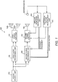
- Fig. 1 is a block diagram showing a schematic configuration of the seat audio system.
- a seat audio system 100 includes a sound source unit (sound source) 110, a first audio processing unit 120, a first power amplifier 130, a first speaker 140L, a second speaker 140R, a second audio processing unit 200, a second power amplifier 150, and a subwoofer
- the seat audio system 100 also includes a microphone 310, an impulse response measurement unit 320, and a distortion factor measurement unit 330.
- the sound source unit 110 outputs L-channel and R-channel audio signals to the first audio processing unit 120 and second audio processing unit 200.
- the sound source unit 110 need not output normal music audio signals and may output, for example, mobile phone ringtones or various types of warning sounds. If the seat audio system 100 is used as a car-mounted audio system, for example, the sound source unit 110 can output, as audio signals, a warning sound in conjunction with a warning display on a meter panel, or can output a detection warning sound as audio signals when an obstacle is detected by an outside-car obstacle detector.
- the sound source unit 110 is not limited to devices having a function of reproducing audio signals, such as a CD or DVD, and may be a sound source unit having a function of acquiring audio signals outputted (reproduced) by another device through, for example, an external input terminal and outputting them to at least the second audio processing unit 200 or the like.
- the first audio processing unit 120 performs processing, such as volume control, on the audio signals acquired from the sound source unit 110.
- the first audio processing unit 120 is a volume control device for controlling the volume of the received audio signals, or an equalizer for performing sound field correction or the like in accordance with the preference of the listener. After performing audio processing such as volume control, the first audio processing unit 120 outputs the resulting audio signals to the first power amplifier 130.
- the first power amplifier 130 amplifies the audio signals received from the first audio processing unit 120 and outputs the resulting audio signals to the first speaker 140L and second speaker 140R.
- the first speaker 140L and second speaker 140R are full-range speakers capable of outputting low-to-high wide-range signals.
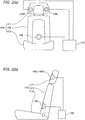
- Figs. 2(a) and 2(b) show an example of a state in which the first speaker 140L, second speaker 140R, and subwoofer 160 are disposed in a seat (vibration transmission member, chair) 170.
- the seat 170 aims to acoustically provide music or the like to a seated listener, as well as to allow the listener to perceive vibration on the basis of low-frequency components of music or the like.
- the seat 170 includes a headrest 171, a backrest (vibration transmission member) 172, and a sitting part 173.
- the first speaker 140L and second speaker 140R are disposed in the headrest 171 of the seat 170 so as to be near the left and right ears of the listener. By disposing the first speaker 140L and second speaker 140R in these positions, the listener is allowed to listen to the L-channel and R-channel audio signals from the horizontal direction.
- the sitting part 173 is structured to support the seated listener from below and has the backrest 172 tiltably mounted thereon.
- the backrest 172 has therein the subwoofer 160 in such a manner that the listener seated on the seat 170 can perceive the vibration of an audio output. For example, as shown in Fig. 2 , disposing the subwoofer 160 around the waist of the listener allows vibration to be transmitted from the waist to the back.
- an exciter is used as an example of the subwoofer 160.
- the listener can adjust the tilt angle of the backrest 172 in accordance with his or her preference.
- the backrest 172 is structured to support the back of the listener, whereas the headrest 171 mounted on an upper portion of the backrest 172 is structured to support the head of the listener.
- the listener can listen to, as sounds, the L-channel audio signal from the first speaker 140L disposed near the left ear, the R-channel audio signal from the second speaker 140R disposed near the right ear, and the low-frequency audio signal from the subwoofer 160, as well as can perceive, as vibration, the audio signal through the backrest 172.
- the second audio processing unit 200 extracts only low-frequency components from the audio signals received from the sound source unit 110 and frequency-converts the extracted low-frequency audio signal. A specific configuration of the second audio processing unit 200 and a process performed thereby will be described later.
- the second audio processing unit 200 outputs the resulting low-frequency audio signal to the second power amplifier 150.
- the second power amplifier 150 amplifies the audio signal received from the second audio processing unit 200 and then outputs the resulting audio signal to the subwoofer 160.
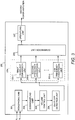
- Fig. 3 is a block diagram showing a schematic configuration of the second audio processing unit 200.
- the second audio processing unit 200 includes a monophonic unit 201, a downsampling unit 202, a volume control unit 203, an envelope detection unit 204, n number of frequency conversion units 205 (a first frequency conversion unit 205-1, a second frequency conversion unit 205-2, ... and an n-th frequency conversion unit 205-n), a combination unit 206, and an upsampling unit 207.
- the monophonic unit 201 combines the L-channel and R-channel audio signals received from the sound source unit 110 into a monophonic signal.
- the monophonic unit 201 outputs the monophonic audio signal to the downsampling unit 202.
- the downsampling unit 202 passes the monophonic audio signal through a low-pass filter and then decimates the resulting signal by reducing the sampling frequency. As seen above, the downsampling unit 202 reduces the data amount of the audio signal to be processed by decimating the signal.
- the cut-off frequency of the low-pass filter of the downsampling unit 202 is set on the basis of the frequency range of the sound source, of an audio signal outputted from the subwoofer 160.
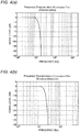
- Fig. 4(a) is a diagram showing frequency characteristics of an example of the low-pass filter used by the downsampling unit 202 of the present embodiment.
- the downsampling unit 202 of the present embodiment uses a 1,024-tap FIR filter as a low-pass filter and sets the cut-off frequency to 150 Hz.
- the downsampling unit 202 sets the downsampling number to 32 and decimates the resulting audio signal with a reduced sampling frequency.
- the audio signal sampled with a sampling frequency of 44.1 kHz is downsampled to 1.38 kHz.
- the volume control unit 203 controls the volume of the downsampled audio signal.
- the listener can control the level of the low-frequency signal outputted from the subwoofer 160 to a desired level by controlling the volume using the volume control unit 203.
- the envelope detection unit 204 detects an envelope of the audio signal by detecting the absolute value of the audio signal volume-controlled by the volume control unit 203 and then integrating (filtering) the absolute value using a low-pass filter.
- Fig. 4(b) shows an example of frequency characteristics of a low-pass filter of the envelope detection unit 204 when reproducing, as music, the audio signal from the sound source unit 110.
- the low-pass filter shown in Fig. 4(b) is a 256-tap FIR filter, and the cut-off frequency is set to 20 Hz.
- Fig. 5(a) shows the waveform of the signal inputted to the envelope detection unit 204 (the signal downsampled by the downsampling unit 202 and then volume-controlled by the volume control unit 203).
- Fig. 5(b) shows the waveforms of the signal obtained by detecting the absolute value using the envelope detection unit 204 (the absolute value detection signal) and the signal obtained by integrating (filtering) the absolute value using the low-pass filter (the low-pass filter output signal).
- Fig. 6 shows frequency characteristics of the downsampled signal, absolute value detection signal, and low-pass filter output signal.
- the envelope detection unit 204 detects an envelope signal by processing the received downsampled signal to detect an absolute value detection signal and then generating a low-pass filter output signal.
- the envelope signal (low-pass filter output signal) shown in Fig. 6 indicates that an audio signal of 20 Hz or less has been detected as a baseband signal.
- the frequency conversion units 205 frequency-convert the envelope signal serving as a baseband signal on the basis of resonant frequencies.
- the resonant frequencies used by the frequency conversion units 205 are determined on the basis of the frequency state (more specifically, peak frequencies) of an impulse response measured by the impulse response measurement unit 320 shown in Fig. 1 .
- Fig. 7 shows an example of frequency characteristics of an impulse response obtained by measuring, using the microphone 310, an audio signal (impulse signal) outputted from an exciter serving as the subwoofer 160.
- an audio signal impulse signal
- Fig. 7 shows frequency characteristics obtained by Fourier-transforming the measured impulse response.
- Fig. 7 reveals that two peak frequencies having high signal levels and serving as resonant frequencies have been detected in the sound reproduction characteristics.
- the resonant frequency of the first frequency conversion unit 205-1 is set to the first resonant frequency of 28 Hz.
- the resonant frequency of the second frequency conversion unit 205-2 is set to the second resonant frequency of 56 Hz.
- the first frequency conversion unit 205-1 multiplies the baseband signal (envelope signal) detected by the envelope detection unit 204 by a sine wave of 28 Hz, which is the same as the resonant frequency, and thus generates a low-frequency signal where the resonant frequency of 28 Hz is emphasized.
- the second frequency conversion unit multiplies the baseband signal (envelope signal) detected by the envelope detection unit 204 by a sine wave of 56 Hz, which is the same as the resonant frequency, and thus generates a low-frequency signal where the resonant frequency of 56 Hz is emphasized.
- the two frequencies, 28 Hz and 56 Hz are detected as resonant frequencies, as shown in Fig. 7 .
- n number of frequency conversion units 205-1 to 205-n perform frequency conversion on the basis of the n number of resonant frequencies.
- the combination unit 206 combines the baseband signals frequency-converted by the n number of frequency conversion units 205.
- the combination unit 206 combines the baseband signals by adding the signals frequency-converted by the respective frequency conversion units 205 (the first to n-th frequency conversion units 205-1 to 205-n). Due to this combination process, the signals frequency-converted so as to correspond to the respective resonant frequencies are combined into one signal.
- the "frequency conversion process" of the present invention refers to a process including the two processes: frequency conversion performed by the frequency conversion units 205 and the combination process performed by the combination unit 206.
- the combination unit 206 outputs the combined low-frequency signal to the upsampling unit 207.
- the upsampling unit 207 inserts zero corresponding to the upsampling number into the signal received from the combination unit 206 and then removes aliasing components using a low-pass filter similar to that of the downsampling unit. For example, when the upsampling number is 32, the sampling frequency of 1.38 kHz is converted to 44.1 kHz, which is similar to the sampling frequency of the audio signal outputted from the sound source unit 110.
- Fig. 8(a) shows changes in the level of the audio signal inputted to the second power amplifier 150 (the audio signal upsampled by the upsampling unit 207).
- Fig. 8(b) shows frequency characteristics of the audio signal in Fig. 8(a).
- Fig. 8(c) shows changes in the level of a signal sound collected by the microphone 310 near the surface of the seat 170.
- Fig. 8(d) shows frequency characteristics of the collected signal sound.
- 8(a) to 8(d) represents the low-frequency signal outputted to the second power amplifier 150 without being frequency-converted by the frequency conversion units 205; a "controlled" signal represents the signal frequency-converted by the frequency conversion units 205 using a resonant frequency of 28 Hz.
- the levels of the controlled and non-controlled audio signals inputted to the second power amplifier 150 are approximately the same.
- a comparison between the levels of the signal sounds outputted from the subwoofer 160 and then collected near the surface of the seat 170 reveals that the level of the non-controlled signal is lower than the controlled signal by 20 dB or more. That is, the vibration level of the signal frequency-converted using the resonant frequency is determined to be higher by 20 dB or more, on the basis of a comparison between the vibration states of the surface of the seat 170.
- the listener seated on the seat 170 could not perceive the same vibration as that of the controlled signal unless the non-controlled signal is outputted with a higher level than that of the controlled signal by 20 dB or more.
- the listener could perceive sufficient vibration even when outputting the controlled signal with a lower level than that of the non-controlled signal.
- Figs. 9(a) to 9(d) show level changes ( Fig. 9(a) ) and frequency characteristics ( Fig. 9(b) ) of the audio signal inputted to the second power amplifier 150 and level changes ( Fig. 9(c) ) and frequency characteristics ( Fig. 9(d) ) of a signal sound collected by the microphone 310.
- a controlled signal shown in Figs. 9(a) to 9(d) differs from that in Figs. 8(a) to 8(d) in that the signal has been frequency-converted using a resonant frequency of 28 Hz, as well as a resonant frequency of 56 Hz.
- resonant frequencies of the subwoofer 160 are previously detected, and an audio signal outputted from the subwoofer 160 is frequency-converted using the detected resonant frequencies.
- the listener is allowed to perceive low-frequency vibration increased using the resonance of the audio signal at the resonant frequencies.
- it is possible to reduce the signal output and to achieve a significant power saving compared to when frequency conversion is not performed using resonant frequencies.
- frequency characteristics of the audio signals tend to vary in various manners. For example, as shown in Fig. 7 , when frequency characteristics are obtained from an impulse response, frequencies having high signal levels can be obtained as resonant frequencies; however, when music or the like is outputted from the subwoofer 160, the frequency characteristics significantly vary. Consequently, the signal levels of frequencies other than resonant frequencies may be outputted as peaks, or the signal level may vary due to the occurrence of a dip.
- the level of the vibration outputted from the subwoofer 160 tends to depend on characteristics of music (music signal) outputted from the sound source unit 110 and thus to significantly vary.
- the amount of a low-frequency sound reproduced by the full-range speakers (the first speaker 140L and second speaker 140R) disposed in the headrest 171 and the amount of low-frequency vibration outputted from the subwoofer 160 may be mismatched. The listener may feel a difference between the sound he or she is listening to and the vibration he or she is perceiving.
- the vibration is controlled by frequency-converting the low-frequency audio signal using the resonant frequencies of the subwoofer 160. Due to this frequency conversion process, the listener is allowed to perceive vibration that does not depend on variations in the frequency characteristics of the music signal outputted from the sound source and corresponds to vibration characteristics of the signal. By controlling the low-frequency signal by frequency conversion using the resonant frequencies as described above, the listener is allowed to perceive vibration (the amount of vibration) corresponding to the amount of a sound reproduced by the full-range speakers.
- the subwoofer 160 is allowed to reproduce a high-level signal.
- the signal may be clipped and distorted.
- the voice coil may burn out.
- the second audio processing unit additionally performs a process of compressing the dynamic range in accordance with the signal level so as to prevent the reproduction of a signal having a level exceeding the reproduction capability of the subwoofer 160.
- Fig. 10 is a block diagram showing a schematic configuration of a second audio processing unit 200a that differs from the configuration of the second audio processing unit 200 shown in Fig. 3 .
- n number of dynamic range compression units 208 (a first dynamic range compression unit 208-1, a second dynamic range compression unit 208-2, ... and an n-th dynamic range compression unit 208-n) corresponding to the number n of disposed frequency conversion units 205 are disposed between the envelope detection unit 204 and frequency conversion units 205.
- the monophonic unit 201, the downsampling unit 202, the volume control unit 203, the envelope detection unit 204, the frequency conversion units 205, the combination unit 206, and the upsampling unit 207 shown in Fig. 10 are the same as those described with reference to Fig. 3 and given the same reference signs. These components will not be described.
- the envelope detection unit 204 outputs an audio signal to the first to n-th dynamic range compression units 208-1 to 208-n.
- the dynamic range compression units 208 each include a level conversion unit 209 (a level conversion unit corresponding to the n-th dynamic range compression unit 208-n will be referred to as an n-th level conversion unit 209-n) and a multiplication unit 210 (the multiplication units 210 disposed in the n number of dynamic range compression units 208 have the same configuration).
- the level conversion units 209-1 to 209-n level-convert the resonant frequencies of the corresponding frequency conversion units 205-1 to 205-n using a lookup table.
- the multiplication units 210 adjust (reduce/compress) the level of the audio signal outputted from the envelope detection unit 204 by multiplying the audio signal by the signals level-converted by the level conversion units 209.
- an audio signal level exceeding the reproduction capability of the subwoofer 160 is previously reduced.
- the distortion of the output sound, the burnout of the subwoofer 160, or the like can be prevented.
- the lookup table for the level conversion units 209 is determined on the basis of the capability for reproducing the respective resonant frequencies of the subwoofer 160.
- a signal level serving as the upper limit of the reproduction capability of the subwoofer 160 is determined on the basis of a distortion factor measured by the distortion factor measurement unit 330 shown in Fig. 1 .
- the distortion factor measurement unit 330 outputs the sine waves having the same frequencies as the resonant frequencies to the second power amplifier 150 while changing the levels of the sine waves. Then, using the microphone 310, the distortion factor measurement unit 330 collects a low-frequency sound outputted from the subwoofer 160 through the second power amplifier 150 and detects a distortion factor from the collected low-frequency sound.
- a signal level serving as the upper limit of the reproduction capability is determined on the basis of the distortion factor.
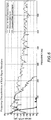
- Fig. 11 is a graph showing an example of measurement results such as distortion factor.
- Fig. 11 shows the measurement results when the signal level has been changed from -18 dB to 0 dB using a sine wave of 56 Hz, which is one of the resonant frequencies of the subwoofer 160, and outputted to the second power amplifier 150.
- the reason why the signal level represented by the horizontal axis of Fig. 11 is in a range of -18 dB to 0 dB is that this range corresponds to the variable range of the signal level.
- Fig. 11 also shows the levels of signal components of all frequencies (the values of all components in Fig.
- Fig. 11 also shows, as distortion components, signal components resulting from the removal of the signal component of 56 Hz (the primary component) from signal components of all frequencies (all components).
- Fig. 11 also shows a distortion factor obtained by subtracting the distortion components from the primary component (note that a subtraction in decibel corresponds to a division in linear value).
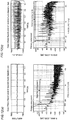
- Figs. 12(a) and 12(b) include diagrams showing the amplitude of an inputted audio signal (upper diagrams) and diagrams showing frequency characteristics of signal components of all frequencies, including the primary component and distortion components (lower diagrams). More specifically, Fig. 12(a) shows the amplitude of the signal level (the upper diagram of Fig. 12(a) ) and frequency characteristics of the signal components of all frequencies (the lower diagram of Fig. 12 (a) ) when the level of the inputted audio signal is low. Fig. 12(b) shows the amplitude of the signal level (the upper diagram of Fig. 12(b) ) and frequency characteristics of the signal components of all frequencies (the lower diagram of Fig. 12 (b) ) when the level of the inputted audio signal is high.
- the distortion components are signal components of higher frequencies than 56 Hz, which represents the peak of the primary component, and correspond to signal components in the range in which the signal level significantly varies. That is, as shown in the lower diagrams of Figs. 12(a) and 12(b) , the components resulting from the removal of the signal component (primary component) of 56 Hz from the signal components of all frequencies (all components) are extracted as the distortion components.
- a signal level at which a distortion factor is -10 dB is defined as the reproduction capability of the subwoofer 160.
- the distortion factor (dB) represented by the vertical axis of Fig. 11 is -10 dB
- the signal level of the reproduction capability represented by the horizontal axis is -11.5 dB.
- the first level conversion unit 209-1 which converts the signal level at which the resonant frequency is 56 Hz, sets a lookup table in such a manner that the upper limit signal level is -11.5 dB.
- Fig. 13 is a diagram showing conversion characteristics of the signal level reduced by the first dynamic range compression unit 208-1 on the basis of the lookup table set by the first level conversion unit 209-1. As shown in Fig. 13 , the input signal level serves as the output signal level until the input signal level becomes -13.5 dB, and therefore the signal level is not reduced.
- a signal reduction process is started.
- the input signal level becomes 0 dB (full scale)
- the input signal level is reduced so that the output signal level becomes -11.5 dB, which is a signal level obtained from the distortion factor shown in Fig. 11 and representing the reproduction capability.
- a lookup table is set on the basis of the reproduction capability of the subwoofer 160 defined on the basis of the distortion factor, and the dynamic range compression units 208 perform signal level reduction processes (dynamic range compression processes). Due to these reduction processes, the signal level of a low-frequency sound to be outputted from the subwoofer 160 is prevented from exceeding the upper limit of the reproduction capability of the subwoofer 160. Thus, the distortion of a low-frequency sound outputted from the subwoofer 160 can be prevented and/or the burnout of the subwoofer 160 can be prevented.
- Fig. 14 is a diagram showing, on the basis of the level of an audio signal inputted to the second power amplifier 150, signal level changes when the dynamic range compression units 208 perform compression processes ("reduced” in Fig. 14 ) and signal level changes when the dynamic range compression units 208 do not perform compression processes ("not reduced” in Fig. 14 ) in a case in which the levels (volumes) of audio signals outputted from the sound source unit 110 are high.
- Fig. 14 shows a case in which the signal level has been increased by increasing the volume of the level of the controlled signal shown in Fig. 8(a) by 11 dB.
- the dynamic range compression units 208 do not reduce (limit) the signal level. Accordingly, the level of the audio signal inputted to the second power amplifier 150 is higher than -11.5 dB, which is the upper limit of the reproduction capability of the subwoofer 160.
- the dynamic range compression units 208 reduce (limit) the signal level. Accordingly, the level of the audio signal inputted to the second power amplifier 150 is confined within -11.5 dB, which is the upper limit of the reproduction capability of the subwoofer 160.
- the signal level of a low-frequency sound to be outputted from the subwoofer 160 is also confined within the range (the upper limit) of the reproduction capability of the subwoofer 160.
- the distortion of the output sound and/or the burnout of the subwoofer 160 can be effectively prevented.
- the seat audio system 100 of the present embodiment frequency-converts a low-frequency sound to be outputted from the subwoofer 160, on the basis of the resonant frequencies of the subwoofer 160 and thus can effectively increase the vibration of the low-frequency sound.
- a reduction in the output of the second power amplifier 150 and a significant power saving are easily achieved.
- the seat audio system 100 of the present embodiment obtains changes in the distortion factor on the basis of a signal component (a primary component) corresponding to each resonant frequency and determines a signal level serving as the upper limit of the reproduction capability on the basis of the distortion factor of the subwoofer 160 set as the upper limit of the reproduction capability of the subwoofer 160.
- the seat audio system 100 sets a lookup table for the level conversion units 209. Using the set lookup table for the level conversion units 209, the seat audio system 100 reduces the levels of audio signals outputted from the dynamic range compression units 208.
- a low-frequency sound having a signal level exceeding the reproduction capability of the subwoofer 160 can be prevented from being outputted from the subwoofer 160.
- the distortion of a sound (low-frequency sound) outputted from the subwoofer 160 and/or the burnout of the subwoofer 160 can be effectively prevented.
- the seat audio system 100 of the present embodiment allows the listener to perceive an output sound as vibration. For example, by inputting a warning sound or the like in conjunction with a warning system as an audio signal of the sound source unit 110, the seat audio system 100 allows the listener to listen to a warning as a warning sound, as well as to perceive the warning as vibration. That is, it is possible to transmit an audio signal to the listener as vibration and thus to more effectively notify the listener of the warning.
- the subwoofer 160 is disposed in the backrest 172 of the seat 170.
- the back of the listener seated on the seat 170 is always in contact with the backrest 172 of the seat 170.
- vibration can be reliably transmitted to the listener.
- the listener seated on the seat 170 can perceive vibration through a wider surface (vibration transmission surface) of the backrest 172 or the like and thus can more reliably perceive the vibration.
- vibration audio system according to the embodiment of the present invention has been described using the seat audio system 100 as an example, the vibration audio system according to the present invention are not limited to the embodiment.
- the subwoofer 160 of the seat audio system 100 is disposed in the backrest 172 of the seat 170, it may be disposed in other positions as long as the listener is allowed to perceive a low-frequency sound as vibration.
- the subwoofer 160 may be disposed in the sitting part 173, headrest 171, or the like of the seat 170.
- the subwoofer 160 only has to be disposed in an object that contacts part of the body of the listener and can transmit vibration.
- it may be disposed in the steering wheel, armrest, or the floor mat of the vehicle.
- the level of the output signal is moderately reduced as the input signal is increased from -13.5 dB to 0 dB, so as to prevent the listener from feeling strange about signal level changes caused by the output signal reduction process.
- the reduction of the signal level need not be performed in this range.
- the reduction of the input signal level need not be started at -13.5 dB and may be started at other signal levels.
Landscapes
- Engineering & Computer Science (AREA)
- Physics & Mathematics (AREA)
- Acoustics & Sound (AREA)
- Signal Processing (AREA)
- Mechanical Engineering (AREA)
- Health & Medical Sciences (AREA)
- General Health & Medical Sciences (AREA)
- Otolaryngology (AREA)
- Circuit For Audible Band Transducer (AREA)
- Details Of Audible-Bandwidth Transducers (AREA)
Abstract
Description
- The present invention relates to a vibration audio system, a vibration audio output method, and a vibration audio program. More specifically, the invention relates to a vibration audio system, a vibration audio output method, and a vibration audio program that allow the listener to perceive, as vibration, a sound outputted from an sound source.
- There have been proposed many seat audio systems whose speaker is disposed in a car seat in order to increase sound effects in the car interior (for example, see
Patent Literatures 1 and 2). A typical seat audio system includes a full-range speaker which is disposed near the headrest of a seat and can reproduce a low-to-high wide-range sound and a subwoofer which is disposed in a mid portion or a lower portion of the seat and can predominantly reproduce a low-frequency sound. - By disposing a subwoofer so as to be embedded in a seat, the seat vibrates in accordance with the level of a low-frequency signal of music, and the vibration is transmitted to the listener. A combination of a sound and vibration can provide higher realism to the listener. Typical examples of a subwoofer embedded in a seat include dynamic speakers, which use a cone paper or the like, and exciters, which output a sound by vibrating the contact surface.
- Further, by outputting various types of warning sounds from a sound source, such a subwoofer can not only give an acoustic warning to the listener using a sound (warning sound) but also give a tactile warning to the listener using vibration. Thus, it is possible to increase the degree to which the listener recognizes the warning.
-
- PTL 1: Japanese Unexamined Patent Application Publication No.
2007-65038 - PTL 2: Japanese Unexamined Patent Application Publication No.
2008-72165 - However, in the case of a seat audio system whose subwoofer is embedded in a seat so that the listener perceives audio output and vibration, a sound outputted from the subwoofer tends to significantly attenuate in the middle of traveling from the inside to the surface of the seat, and the vibration components tend to significantly attenuate as well. For this reason, the subwoofer needs to output a high-level audio signal so that the listener seated on the seat sufficiently perceives vibration. However, outputting a high-level audio signal requires a power amplifier having a high amplification factor and a large output, disadvantageously resulting in an increase in power consumption and an increase in cost.
- In particular, giving a warning using vibration requires creating large vibration so that the person seated on the seat reliably becomes aware of the warning. Consequently, power consumption and cost are further increased.
- Similarly, when a subwoofer is disposed in a member other than a seat capable of transmitting vibration, the output (vibration) of a sound disadvantageously significantly attenuates before the listener perceives the vibration.
- The present invention has been made in view of the foregoing, and an object thereof is to provide a vibration audio system, vibration audio output method, and vibration audio program that when transmitting an audio signal outputted from a sound source to the listener in the form of vibration, can output vibration that the listener can perceive while reducing the output level of the signal and reducing power consumption.
- In order to solve the above problems, a vibration audio system of one aspect of the present invention includes an envelope detection unit configured to detect an envelope signal by obtaining an absolute value of amplitude of an audio signal outputted from a sound source and then integrating the absolute value, a vibration transmission member having therein a low-frequency output speaker for outputting the audio signal and configured to allow a listener to perceive vibration of a low-frequency sound outputted from the low-frequency output speaker, and a frequency conversion unit configured to generate an audio signal frequency-converted on the basis of resonant frequencies by multiplying the envelope signal by sine waves, the resonant frequencies being obtained from an impulse response of the low-frequency output speaker disposed in the vibration transmission member, the sine waves having the same frequencies as the resonant frequencies. The audio signal frequency-converted by the frequency conversion unit is outputted from the low-frequency output speaker.
- A vibration audio output method of another aspect of the present invention includes an envelope detection step of, by an envelope detection unit, detecting an envelope signal by obtaining an absolute value of amplitude of an audio signal outputted from a sound source and then integrating the absolute value, a frequency conversion step of, by a frequency conversion unit, generating an audio signal frequency-converted on the basis of resonant frequencies by multiplying the envelope signal by sine waves, the resonant frequencies being obtained from an impulse response of a low-frequency output speaker disposed in a vibration transmission member configured to allow a listener to perceive vibration of a low-frequency sound, the sine waves having the same frequencies as the resonant frequencies, and an audio signal output step of, by the low-frequency output speaker, outputting the audio signal frequency-converted in the frequency conversion step.
- Yet another aspect of the present invention provides a vibration audio program for a vibration audio system for allowing a listener to perceive vibration of a low-frequency sound through a vibration transmission member by outputting a low-frequency sound from a low-frequency output speaker disposed in the vibration transmission member. The program causes the vibration audio system to perform an envelope detection function of causing an envelope detection unit to detect an envelope signal by obtaining an absolute value of amplitude of an audio signal outputted from a sound source and then to integrate the absolute value, a frequency conversion function of causing a frequency conversion unit to generate an audio signal frequency-converted on the basis of resonant frequencies by multiplying the envelope signal by sine waves, the resonant frequencies being obtained from an impulse response of the low-frequency output speaker, the sine waves having the same frequencies as the resonant frequencies, and an audio signal output function of causing the low-frequency output speaker to output the audio signal frequency-converted by the frequency conversion function.
- The vibration audio system, the vibration audio output method, and the vibration audio program for the vibration audio system frequency-convert a low-frequency sound outputted from the low-frequency output speaker disposed in the vibration transmission member on the basis of the resonant frequencies of the low-frequency output speaker and thus can effectively increase the signal level of the low-frequency sound. As a result, the vibration transmitted to the listener through the vibration transmission member can be increased by performing frequency conversion using the resonant frequencies. Thus, when causing the listener to perceive the same vibration as conventional vibration, it is possible to reduce the signal level of a low-frequency sound outputted from the low-frequency output speaker compared to the conventional signal level, as well as to significantly reduce the amount of power of the amplifier or the like.
- Further, the listener is allowed to perceive, as vibration, a low-frequency sound outputted from the low-frequency output speaker, and this vibration can be increased by performing frequency conversion on the basis of the resonant frequencies. Thus, for example, when giving a warning or the like to the listener, the warning or the like can be given to the listener using a sound, as well as vibration.
- The vibration audio system may further include a distortion factor measurement unit configured to obtain a distortion component by removing signal components of the resonant frequencies from signal components of all frequencies of a low-frequency sound, the low-frequency sound being obtained by causing the low-frequency output speaker to output the sine waves having the same frequencies as the resonant frequencies while changing signal levels of the sine waves and then by collecting the sine waves, and to measure a distortion factor of the low-frequency output speaker by calculating a ratio of the signal components of the resonant frequencies to the distortion component in accordance with the changed signal level and a dynamic range compression unit configured to reduce a signal level of the envelope signal for each of the resonant frequencies on the basis of the distortion factor measured by the distortion factor measurement unit so that a signal level of a low-frequency sound outputted from the low-frequency output speaker becomes equal to or lower than an upper limit of a signal level that can be reproduced by the low-frequency output speaker. The frequency conversion unit frequency-converts the envelope signal whose signal level has been reduced by the dynamic range compression unit.
- The vibration audio output method may further include a distortion factor measurement step of, by a distortion factor measurement unit, obtaining a distortion component by removing signal components of the resonant frequencies from signal components of all frequencies of a low-frequency sound, the low-frequency sound being obtained by causing the low-frequency output speaker to output the sine waves having the same frequencies as the resonant frequencies while changing signal levels of the sine waves and then by collecting the sine waves, and measuring a distortion factor of the low-frequency output speaker by calculating a ratio of the signal components of the resonant frequencies to the distortion component in accordance with the changed signal level and a dynamic range compression step of, by a dynamic range compression unit, reducing a signal level of the envelope signal for each of the resonant frequencies on the basis of the distortion factor measured in the distortion factor measurement step so that a signal level of a low-frequency sound outputted from the low-frequency output speaker becomes equal to or lower than an upper limit of a signal level that can be reproduced by the low-frequency output speaker. In the frequency conversion step, the frequency conversion unit frequency-converts the envelope signal whose signal level has been reduced in the dynamic range compression step.
- The vibration audio program for the vibration audio system may cause the vibration audio system to further perform a distortion factor measurement function of causing a distortion factor measurement unit to obtain a distortion component by removing signal components of the resonant frequencies from signal components of all frequencies of a low-frequency sound, the low-frequency sound being obtained by causing the low-frequency output speaker to output the sine waves having the same frequencies as the resonant frequencies while changing signal levels of the sine waves and then by collecting the sine waves, and to measure a distortion factor of the low-frequency output speaker by calculating a ratio of the signal components of the resonant frequencies to the distortion component in accordance with the changed signal level and a dynamic range compression function of causing a dynamic range compression unit to reduce a signal level of the envelope signal for each of the resonant frequencies on the basis of the distortion factor measured by the distortion factor measurement function so that a signal level of a low-frequency sound outputted from the low-frequency output speaker becomes equal to or lower than an upper limit of a signal level that can be reproduced by the low-frequency output speaker. The frequency conversion function causes the frequency conversion unit to frequency-convert the envelope signal whose signal level has been reduced by the dynamic range compression function.
- The above vibration audio system, the vibration audio output method, and the vibration audio program for the vibration audio system measure the distortion factor of the low-frequency output speaker on the basis of the signal components of the resonant frequencies. The vibration audio system and the like then reduce the level of the envelope signal for each resonant frequency on the basis of the distortion factor so that the signal level of a low-frequency sound outputted from the low-frequency output speaker becomes equal to or lower than the upper limit of the signal level that can be reproduced by the low-frequency output speaker, and then frequency-convert the audio signal. Thus, it is possible to prevent the output of a low-frequency sound having a signal level exceeding the reproduction capability of the low-frequency output speaker. As a result, it is possible to effectively prevent the distortion of a low-frequency sound outputted from the low-frequency output speaker and/or the burnout of the low-frequency output speaker.
- In the vibration audio system, the vibration audio output method, and the vibration audio program for the vibration audio system, the vibration transmission member may be a chair on which the listener is seated.
- By using, as the vibration transmission member, the chair on which the listener is seated, the listener is always in contact with the vibration transmission member for transmitting a low-frequency sound in the form of vibration. Thus, vibration can be reliably transmitted to the listener. Further, the listener seated on the chair can perceive vibration through a wider surface of the sitting part, backrest, or the like and thus can more reliably perceive the vibration.
- The vibration audio system, the vibration audio output method, and the vibration audio program for the vibration audio system of the present invention frequency-convert a low-frequency sound outputted from the low-frequency output speaker disposed in the vibration transmission member on the basis of the resonant frequencies of the low-frequency output speaker and can effectively increase the signal level of the low-frequency sound. As a result, the vibration transmitted to the listener through the vibration transmission member can be increased by performing frequency conversion using the resonant frequencies. Thus, when causing the listener to perceive the same vibration as conventional vibration, it is possible to reduce the signal level of a low-frequency sound outputted from the low-frequency output speaker compared to the conventional signal level, as well as to significantly reduce the amount of power of the amplifier or the like.
- Further, the listener is allowed to perceive, as vibration, a low-frequency sound outputted from the low-frequency output speaker, and this vibration can be increased by performing frequency conversion on the basis of the resonant frequencies. Thus, for example, when giving a warning or the like to the listener, the warning or the like can be given to the listener using a sound, as well as vibration.
-
-
Fig. 1 is a block diagram showing a schematic configuration of a seat audio system of the present embodiment; -
Fig. 2 is a diagram showing a state in which a first speaker, a second speaker, and a subwoofer of the present embodiment are disposed in a seat; -
Fig. 3 is a block diagram showing a schematic configuration of a second audio processing unit of the present embodiment; -
Fig. 4(a) is a diagram showing frequency characteristics of an example of a low-pass filter of the present embodiment;Fig. 4(b) is a diagram showing an example of frequency characteristics of a low-pass filter of an envelope detection unit when reproducing, as music, an audio signal from a sound source unit of the present embodiment; -
Fig. 5(a) is a diagram showing the waveform of a downsampled signal inputted to the envelope detection unit of the present embodiment; andFig. 5(b) is a diagram showing the waveform of an absolute value detection signal obtained when the envelope detection unit detects an absolute value and the waveform of a low-pass filter output signal obtained by performing filtering using a low-pass filter; -
Fig. 6 is a diagram showing frequency characteristics of the downsampled signal, absolute value detection signal, and low-pass filter output signal of the present embodiment; -
Fig. 7 is a diagram showing frequency characteristics of an impulse response obtained by the subwoofer of the present embodiment; -
Fig. 8(a) is a diagram showing changes in the level of an audio signal inputted to a second power amplifier;Fig. 8(b) is a diagram showing frequency characteristics of the audio signal inFig. 8(a); Fig. 8(c) is a diagram showing changes in the level of a signal sound collected using a microphone near the surface of a seat; andFig. 8(d) is a diagram showing frequency characteristics of the collected signal sound; -
Fig. 9(a) is a diagram showing changes in the level of another audio signal inputted to the second power amplifier;Fig. 9(b) is a diagram showing frequency characteristics of the audio signal inFig. 9(a); Fig. 9(c) is a diagram showing changes in the level of a signal sound collected using the microphone near the surface of the seat; andFig. 9(d) is a diagram showing frequency characteristics of the collected signal sound; -
Fig. 10 is a block diagram showing a schematic configuration of another second audio processing unit in which n number of dynamic range compression units corresponding to the number n of disposed frequency conversion units are disposed between an envelope detection unit and the frequency conversion units, which differs from the configuration of the second audio processing unit shown inFig. 3 ; -
Fig. 11 is a graph showing an example of the measurement results of the signal components of all components, the signal component of a primary component, and the signal components of distortion components, and a distortion factor of the present embodiment; -
Figs. 12(a) and 12(b) include diagrams showing the amplitude of an inputted audio signal (upper diagrams) and diagrams showing the relationship of the primary component and distortion components with the signal components of all frequencies;Fig. 12(a) shows a case in which the level of the inputted audio signal is low; andFig. 12(b) shows a case in which the level of the inputted audio signal is high; -
Fig. 13 is a diagram showing conversion characteristics of the signal level reduced by a first dynamic range compression unit on the basis of a lookup table set by a first level conversion unit of the present embodiment; and -
Fig. 14 is a diagram showing, on the basis of the value of the signal level of an audio signal inputted to the second power amplifier, signal level changes when dynamic range compression units perform compression processes and signal level changes when the dynamic range compression units do not perform compression processes in a case in which the level of an audio signal outputted from the sound source unit of the present embodiment is high. - Now, a vibration audio system of the present invention will be described in detail using a seat audio system as an example.
Fig. 1 is a block diagram showing a schematic configuration of the seat audio system. - A
seat audio system 100 includes a sound source unit (sound source) 110, a firstaudio processing unit 120, afirst power amplifier 130, afirst speaker 140L, asecond speaker 140R, a secondaudio processing unit 200, asecond power amplifier 150, and a subwoofer - (low-frequency output speaker) 160. The
seat audio system 100 also includes amicrophone 310, an impulseresponse measurement unit 320, and a distortionfactor measurement unit 330. - The
sound source unit 110 outputs L-channel and R-channel audio signals to the firstaudio processing unit 120 and secondaudio processing unit 200. Thesound source unit 110 need not output normal music audio signals and may output, for example, mobile phone ringtones or various types of warning sounds. If theseat audio system 100 is used as a car-mounted audio system, for example, thesound source unit 110 can output, as audio signals, a warning sound in conjunction with a warning display on a meter panel, or can output a detection warning sound as audio signals when an obstacle is detected by an outside-car obstacle detector. Thesound source unit 110 is not limited to devices having a function of reproducing audio signals, such as a CD or DVD, and may be a sound source unit having a function of acquiring audio signals outputted (reproduced) by another device through, for example, an external input terminal and outputting them to at least the secondaudio processing unit 200 or the like. - The first
audio processing unit 120 performs processing, such as volume control, on the audio signals acquired from thesound source unit 110. For example, the firstaudio processing unit 120 is a volume control device for controlling the volume of the received audio signals, or an equalizer for performing sound field correction or the like in accordance with the preference of the listener. After performing audio processing such as volume control, the firstaudio processing unit 120 outputs the resulting audio signals to thefirst power amplifier 130. - The
first power amplifier 130 amplifies the audio signals received from the firstaudio processing unit 120 and outputs the resulting audio signals to thefirst speaker 140L andsecond speaker 140R. Thefirst speaker 140L andsecond speaker 140R are full-range speakers capable of outputting low-to-high wide-range signals. -
Figs. 2(a) and 2(b) show an example of a state in which thefirst speaker 140L,second speaker 140R, andsubwoofer 160 are disposed in a seat (vibration transmission member, chair) 170. Theseat 170 aims to acoustically provide music or the like to a seated listener, as well as to allow the listener to perceive vibration on the basis of low-frequency components of music or the like. Theseat 170 includes aheadrest 171, a backrest (vibration transmission member) 172, and a sittingpart 173. - As shown in
Figs. 2(a) and 2(b) , thefirst speaker 140L andsecond speaker 140R are disposed in theheadrest 171 of theseat 170 so as to be near the left and right ears of the listener. By disposing thefirst speaker 140L andsecond speaker 140R in these positions, the listener is allowed to listen to the L-channel and R-channel audio signals from the horizontal direction. - The sitting
part 173 is structured to support the seated listener from below and has thebackrest 172 tiltably mounted thereon. - The
backrest 172 has therein thesubwoofer 160 in such a manner that the listener seated on theseat 170 can perceive the vibration of an audio output. For example, as shown inFig. 2 , disposing thesubwoofer 160 around the waist of the listener allows vibration to be transmitted from the waist to the back. In the present embodiment, an exciter is used as an example of thesubwoofer 160. - The listener can adjust the tilt angle of the
backrest 172 in accordance with his or her preference. Thebackrest 172 is structured to support the back of the listener, whereas theheadrest 171 mounted on an upper portion of thebackrest 172 is structured to support the head of the listener. Thus, when thefirst speaker 140L,second speaker 140R, andsubwoofer 160 output audio signals with the listener seated on theseat 170, the listener can listen to, as sounds, the L-channel audio signal from thefirst speaker 140L disposed near the left ear, the R-channel audio signal from thesecond speaker 140R disposed near the right ear, and the low-frequency audio signal from thesubwoofer 160, as well as can perceive, as vibration, the audio signal through thebackrest 172. - The second
audio processing unit 200 extracts only low-frequency components from the audio signals received from thesound source unit 110 and frequency-converts the extracted low-frequency audio signal. A specific configuration of the secondaudio processing unit 200 and a process performed thereby will be described later. The secondaudio processing unit 200 outputs the resulting low-frequency audio signal to thesecond power amplifier 150. - The
second power amplifier 150 amplifies the audio signal received from the secondaudio processing unit 200 and then outputs the resulting audio signal to thesubwoofer 160. -
Fig. 3 is a block diagram showing a schematic configuration of the secondaudio processing unit 200. The secondaudio processing unit 200 includes amonophonic unit 201, adownsampling unit 202, avolume control unit 203, anenvelope detection unit 204, n number of frequency conversion units 205 (a first frequency conversion unit 205-1, a second frequency conversion unit 205-2, ... and an n-th frequency conversion unit 205-n), acombination unit 206, and anupsampling unit 207. - The
monophonic unit 201 combines the L-channel and R-channel audio signals received from thesound source unit 110 into a monophonic signal. Themonophonic unit 201 outputs the monophonic audio signal to thedownsampling unit 202. - To reduce the amount of signal processing operation in the
volume control unit 203,envelope detection unit 204,frequency conversion units 205, andcombination unit 206, thedownsampling unit 202 passes the monophonic audio signal through a low-pass filter and then decimates the resulting signal by reducing the sampling frequency. As seen above, thedownsampling unit 202 reduces the data amount of the audio signal to be processed by decimating the signal. The cut-off frequency of the low-pass filter of thedownsampling unit 202 is set on the basis of the frequency range of the sound source, of an audio signal outputted from thesubwoofer 160. -
Fig. 4(a) is a diagram showing frequency characteristics of an example of the low-pass filter used by thedownsampling unit 202 of the present embodiment. As shown inFig. 4(a) , thedownsampling unit 202 of the present embodiment uses a 1,024-tap FIR filter as a low-pass filter and sets the cut-off frequency to 150 Hz. After filtering the audio signal using the low-pass filter shown inFig. 4(a) , thedownsampling unit 202 sets the downsampling number to 32 and decimates the resulting audio signal with a reduced sampling frequency. Thus, the audio signal sampled with a sampling frequency of 44.1 kHz is downsampled to 1.38 kHz. - The
volume control unit 203 controls the volume of the downsampled audio signal. The listener can control the level of the low-frequency signal outputted from thesubwoofer 160 to a desired level by controlling the volume using thevolume control unit 203. - The
envelope detection unit 204 detects an envelope of the audio signal by detecting the absolute value of the audio signal volume-controlled by thevolume control unit 203 and then integrating (filtering) the absolute value using a low-pass filter. -
Fig. 4(b) shows an example of frequency characteristics of a low-pass filter of theenvelope detection unit 204 when reproducing, as music, the audio signal from thesound source unit 110. The low-pass filter shown inFig. 4(b) is a 256-tap FIR filter, and the cut-off frequency is set to 20 Hz. -
Fig. 5(a) shows the waveform of the signal inputted to the envelope detection unit 204 (the signal downsampled by thedownsampling unit 202 and then volume-controlled by the volume control unit 203).Fig. 5(b) shows the waveforms of the signal obtained by detecting the absolute value using the envelope detection unit 204 (the absolute value detection signal) and the signal obtained by integrating (filtering) the absolute value using the low-pass filter (the low-pass filter output signal).Fig. 6 shows frequency characteristics of the downsampled signal, absolute value detection signal, and low-pass filter output signal. - As shown in
Figs. 5(a), 5(b) , and6 , theenvelope detection unit 204 detects an envelope signal by processing the received downsampled signal to detect an absolute value detection signal and then generating a low-pass filter output signal. The envelope signal (low-pass filter output signal) shown inFig. 6 indicates that an audio signal of 20 Hz or less has been detected as a baseband signal. - The
frequency conversion units 205 frequency-convert the envelope signal serving as a baseband signal on the basis of resonant frequencies. The resonant frequencies used by thefrequency conversion units 205 are determined on the basis of the frequency state (more specifically, peak frequencies) of an impulse response measured by the impulseresponse measurement unit 320 shown inFig. 1 . -
Fig. 7 shows an example of frequency characteristics of an impulse response obtained by measuring, using themicrophone 310, an audio signal (impulse signal) outputted from an exciter serving as thesubwoofer 160. By measuring an impulse response of the audio signal outputted from thesubwoofer 160 using themicrophone 310, it is possible to measure sound reproduction characteristics between thesubwoofer 160 and the surface of thebackrest 172.Fig. 7 shows frequency characteristics obtained by Fourier-transforming the measured impulse response. -
Fig. 7 reveals that two peak frequencies having high signal levels and serving as resonant frequencies have been detected in the sound reproduction characteristics. In the present embodiment, a first peak frequency of 28 Hz is referred to as the first resonant frequency (a resonant frequency where n-1), and a second peak frequency of 56 Hz as the second resonant frequency (a resonant frequency where n=2). - The resonant frequency of the first frequency conversion unit 205-1 is set to the first resonant frequency of 28 Hz. The resonant frequency of the second frequency conversion unit 205-2 is set to the second resonant frequency of 56 Hz.
- The first frequency conversion unit 205-1 multiplies the baseband signal (envelope signal) detected by the
envelope detection unit 204 by a sine wave of 28 Hz, which is the same as the resonant frequency, and thus generates a low-frequency signal where the resonant frequency of 28 Hz is emphasized. The second frequency conversion unit multiplies the baseband signal (envelope signal) detected by theenvelope detection unit 204 by a sine wave of 56 Hz, which is the same as the resonant frequency, and thus generates a low-frequency signal where the resonant frequency of 56 Hz is emphasized. - In the present embodiment, the two frequencies, 28 Hz and 56 Hz, are detected as resonant frequencies, as shown in
Fig. 7 . For this reason, the case in which the two (n=2) frequency conversion units, the first frequency conversion unit 205-1 and second frequency conversion unit 205-2, are provided as thefrequency conversion units 205 has been described as an example. However, if n number of peaks serving as resonant frequencies are detected, n number of frequency conversion units 205-1 to 205-n perform frequency conversion on the basis of the n number of resonant frequencies. - The
combination unit 206 combines the baseband signals frequency-converted by the n number offrequency conversion units 205. Thecombination unit 206 combines the baseband signals by adding the signals frequency-converted by the respective frequency conversion units 205 (the first to n-th frequency conversion units 205-1 to 205-n). Due to this combination process, the signals frequency-converted so as to correspond to the respective resonant frequencies are combined into one signal. The "frequency conversion process" of the present invention refers to a process including the two processes: frequency conversion performed by thefrequency conversion units 205 and the combination process performed by thecombination unit 206. Thecombination unit 206 outputs the combined low-frequency signal to theupsampling unit 207. - The
upsampling unit 207 inserts zero corresponding to the upsampling number into the signal received from thecombination unit 206 and then removes aliasing components using a low-pass filter similar to that of the downsampling unit. For example, when the upsampling number is 32, the sampling frequency of 1.38 kHz is converted to 44.1 kHz, which is similar to the sampling frequency of the audio signal outputted from thesound source unit 110. -
Fig. 8(a) shows changes in the level of the audio signal inputted to the second power amplifier 150 (the audio signal upsampled by the upsampling unit 207).Fig. 8(b) shows frequency characteristics of the audio signal inFig. 8(a). Fig. 8(c) shows changes in the level of a signal sound collected by themicrophone 310 near the surface of theseat 170.Fig. 8(d) shows frequency characteristics of the collected signal sound. A "non-controlled" signal shown inFigs. 8(a) to 8(d) represents the low-frequency signal outputted to thesecond power amplifier 150 without being frequency-converted by thefrequency conversion units 205; a "controlled" signal represents the signal frequency-converted by thefrequency conversion units 205 using a resonant frequency of 28 Hz. - As shown in
Figs. 8(a) and 8(b) , the levels of the controlled and non-controlled audio signals inputted to thesecond power amplifier 150 are approximately the same. However, a comparison between the levels of the signal sounds outputted from thesubwoofer 160 and then collected near the surface of the seat 170 (Figs. 8(c) and 8(d) ) reveals that the level of the non-controlled signal is lower than the controlled signal by 20 dB or more. That is, the vibration level of the signal frequency-converted using the resonant frequency is determined to be higher by 20 dB or more, on the basis of a comparison between the vibration states of the surface of theseat 170. - Accordingly, in the case of the non-controlled signal, the listener seated on the
seat 170 could not perceive the same vibration as that of the controlled signal unless the non-controlled signal is outputted with a higher level than that of the controlled signal by 20 dB or more. In other words, in the case of the controlled signal, the listener could perceive sufficient vibration even when outputting the controlled signal with a lower level than that of the non-controlled signal. Thus, it is possible to reduce the output of thesecond power amplifier 150 and thus to achieve a significant power saving. - As with
Figs. 8(a) to 8(d) ,Figs. 9(a) to 9(d) show level changes (Fig. 9(a) ) and frequency characteristics (Fig. 9(b) ) of the audio signal inputted to thesecond power amplifier 150 and level changes (Fig. 9(c) ) and frequency characteristics (Fig. 9(d) ) of a signal sound collected by themicrophone 310. Note that a controlled signal shown inFigs. 9(a) to 9(d) differs from that inFigs. 8(a) to 8(d) in that the signal has been frequency-converted using a resonant frequency of 28 Hz, as well as a resonant frequency of 56 Hz. The signal levels at 28 Hz and 56 Hz inFigs. 9(a) and 9(b) have been reduced compared to those inFigs. 8(a) and 8(b) by 6 dB. This reduction process has been performed considering that when frequency conversion is performed using two resonant frequencies and then thecombination unit 206 performs a combination process, the signal level is increased compared to that when frequency conversion is performed using only one resonant frequency and then a combination process is performed. - As shown in
Figs. 9(c) and 9(d) , when the vibration state near the surface of theseat 170 is detected using the audio signal frequency-converted using the two resonant frequencies, the level of the controlled signal is detected to be higher than that of the non-controlled signal by 17 dB. As seen above, when frequency conversion is performed using multiple resonant frequencies, the listener can sufficiently perceive the vibration of the controlled signal having a lower level than that of the non-controlled signal. Thus, it is possible to reduce the output of thesecond power amplifier 150 and thus to achieve a significant power saving. - As described above, resonant frequencies of the
subwoofer 160 are previously detected, and an audio signal outputted from thesubwoofer 160 is frequency-converted using the detected resonant frequencies. Thus, the listener is allowed to perceive low-frequency vibration increased using the resonance of the audio signal at the resonant frequencies. As a result, it is possible to reduce the signal output and to achieve a significant power saving compared to when frequency conversion is not performed using resonant frequencies. - When the
sound source unit 110 outputs music audio signals or the like, frequency characteristics of the audio signals tend to vary in various manners. For example, as shown inFig. 7 , when frequency characteristics are obtained from an impulse response, frequencies having high signal levels can be obtained as resonant frequencies; however, when music or the like is outputted from thesubwoofer 160, the frequency characteristics significantly vary. Consequently, the signal levels of frequencies other than resonant frequencies may be outputted as peaks, or the signal level may vary due to the occurrence of a dip. - For this reason, when frequency conversion based on resonant frequencies is not performed, the level of the vibration outputted from the
subwoofer 160 tends to depend on characteristics of music (music signal) outputted from thesound source unit 110 and thus to significantly vary. Thus, the amount of a low-frequency sound reproduced by the full-range speakers (thefirst speaker 140L andsecond speaker 140R) disposed in theheadrest 171 and the amount of low-frequency vibration outputted from thesubwoofer 160 may be mismatched. The listener may feel a difference between the sound he or she is listening to and the vibration he or she is perceiving. - To eliminate such a sound-vibration difference, the vibration is controlled by frequency-converting the low-frequency audio signal using the resonant frequencies of the
subwoofer 160. Due to this frequency conversion process, the listener is allowed to perceive vibration that does not depend on variations in the frequency characteristics of the music signal outputted from the sound source and corresponds to vibration characteristics of the signal. By controlling the low-frequency signal by frequency conversion using the resonant frequencies as described above, the listener is allowed to perceive vibration (the amount of vibration) corresponding to the amount of a sound reproduced by the full-range speakers. - As described above, by performing frequency conversion on the basis of resonant frequencies, the
subwoofer 160 is allowed to reproduce a high-level signal. However, if thesubwoofer 160 outputs a signal having a level exceeding the reproduction capability thereof, the signal may be clipped and distorted. Also, if the signal level becomes equal to or higher than the upper limit of the reproduction capability of thesubwoofer 160, the voice coil may burn out. Hereafter, a case will be described in which the second audio processing unit additionally performs a process of compressing the dynamic range in accordance with the signal level so as to prevent the reproduction of a signal having a level exceeding the reproduction capability of thesubwoofer 160. -
Fig. 10 is a block diagram showing a schematic configuration of a secondaudio processing unit 200a that differs from the configuration of the secondaudio processing unit 200 shown inFig. 3 . In the secondaudio processing unit 200a, n number of dynamic range compression units 208 (a first dynamic range compression unit 208-1, a second dynamic range compression unit 208-2, ... and an n-th dynamic range compression unit 208-n) corresponding to the number n of disposedfrequency conversion units 205 are disposed between theenvelope detection unit 204 andfrequency conversion units 205. Themonophonic unit 201, thedownsampling unit 202, thevolume control unit 203, theenvelope detection unit 204, thefrequency conversion units 205, thecombination unit 206, and theupsampling unit 207 shown inFig. 10 are the same as those described with reference toFig. 3 and given the same reference signs. These components will not be described. - The
envelope detection unit 204 outputs an audio signal to the first to n-th dynamic range compression units 208-1 to 208-n. The dynamicrange compression units 208 each include a level conversion unit 209 (a level conversion unit corresponding to the n-th dynamic range compression unit 208-n will be referred to as an n-th level conversion unit 209-n) and a multiplication unit 210 (themultiplication units 210 disposed in the n number of dynamicrange compression units 208 have the same configuration). - The level conversion units 209-1 to 209-n level-convert the resonant frequencies of the corresponding frequency conversion units 205-1 to 205-n using a lookup table. The
multiplication units 210 adjust (reduce/compress) the level of the audio signal outputted from theenvelope detection unit 204 by multiplying the audio signal by the signals level-converted by thelevel conversion units 209. By providing the level conversion units 209 (209-1 to 209-n) and adjusting (reducing/compressing) the signal levels of the resonant frequencies as described above, an audio signal level exceeding the reproduction capability of thesubwoofer 160 is previously reduced. Thus, the distortion of the output sound, the burnout of thesubwoofer 160, or the like can be prevented. - The lookup table for the
level conversion units 209 is determined on the basis of the capability for reproducing the respective resonant frequencies of thesubwoofer 160. A signal level serving as the upper limit of the reproduction capability of thesubwoofer 160 is determined on the basis of a distortion factor measured by the distortionfactor measurement unit 330 shown inFig. 1 . The distortionfactor measurement unit 330 outputs the sine waves having the same frequencies as the resonant frequencies to thesecond power amplifier 150 while changing the levels of the sine waves. Then, using themicrophone 310, the distortionfactor measurement unit 330 collects a low-frequency sound outputted from thesubwoofer 160 through thesecond power amplifier 150 and detects a distortion factor from the collected low-frequency sound. A signal level serving as the upper limit of the reproduction capability is determined on the basis of the distortion factor. -
Fig. 11 is a graph showing an example of measurement results such as distortion factor.Fig. 11 shows the measurement results when the signal level has been changed from -18 dB to 0 dB using a sine wave of 56 Hz, which is one of the resonant frequencies of thesubwoofer 160, and outputted to thesecond power amplifier 150. The reason why the signal level represented by the horizontal axis ofFig. 11 is in a range of -18 dB to 0 dB is that this range corresponds to the variable range of the signal level.Fig. 11 also shows the levels of signal components of all frequencies (the values of all components inFig. 11 ) and the level of a signal component of 56 Hz, which is a resonant frequency, (the value of the primary component inFig. 11 ) on the basis of a low-frequency sound measured by the distortionfactor measurement unit 330 through themicrophone 310.Fig. 11 also shows, as distortion components, signal components resulting from the removal of the signal component of 56 Hz (the primary component) from signal components of all frequencies (all components).Fig. 11 also shows a distortion factor obtained by subtracting the distortion components from the primary component (note that a subtraction in decibel corresponds to a division in linear value). -
Figs. 12(a) and 12(b) include diagrams showing the amplitude of an inputted audio signal (upper diagrams) and diagrams showing frequency characteristics of signal components of all frequencies, including the primary component and distortion components (lower diagrams). More specifically,Fig. 12(a) shows the amplitude of the signal level (the upper diagram ofFig. 12(a) ) and frequency characteristics of the signal components of all frequencies (the lower diagram ofFig. 12 (a) ) when the level of the inputted audio signal is low.Fig. 12(b) shows the amplitude of the signal level (the upper diagram ofFig. 12(b) ) and frequency characteristics of the signal components of all frequencies (the lower diagram ofFig. 12 (b) ) when the level of the inputted audio signal is high. - As shown in the lower diagrams of
Fig. 12(a) and 12(b) , the distortion components are signal components of higher frequencies than 56 Hz, which represents the peak of the primary component, and correspond to signal components in the range in which the signal level significantly varies. That is, as shown in the lower diagrams ofFigs. 12(a) and 12(b) , the components resulting from the removal of the signal component (primary component) of 56 Hz from the signal components of all frequencies (all components) are extracted as the distortion components. - For example, a signal level at which a distortion factor is -10 dB is defined as the reproduction capability of the
subwoofer 160. In this case, when the distortion factor (dB) represented by the vertical axis ofFig. 11 is -10 dB, the signal level of the reproduction capability represented by the horizontal axis is -11.5 dB. The first level conversion unit 209-1, which converts the signal level at which the resonant frequency is 56 Hz, sets a lookup table in such a manner that the upper limit signal level is -11.5 dB. -
Fig. 13 is a diagram showing conversion characteristics of the signal level reduced by the first dynamic range compression unit 208-1 on the basis of the lookup table set by the first level conversion unit 209-1. As shown inFig. 13 , the input signal level serves as the output signal level until the input signal level becomes -13.5 dB, and therefore the signal level is not reduced. - However, when the input signal level exceeds -13.5 dB, a signal reduction process is started. When the input signal level becomes 0 dB (full scale), the input signal level is reduced so that the output signal level becomes -11.5 dB, which is a signal level obtained from the distortion factor shown in
Fig. 11 and representing the reproduction capability. As seen above, a lookup table is set on the basis of the reproduction capability of thesubwoofer 160 defined on the basis of the distortion factor, and the dynamicrange compression units 208 perform signal level reduction processes (dynamic range compression processes). Due to these reduction processes, the signal level of a low-frequency sound to be outputted from thesubwoofer 160 is prevented from exceeding the upper limit of the reproduction capability of thesubwoofer 160. Thus, the distortion of a low-frequency sound outputted from thesubwoofer 160 can be prevented and/or the burnout of thesubwoofer 160 can be prevented. -
Fig. 14 is a diagram showing, on the basis of the level of an audio signal inputted to thesecond power amplifier 150, signal level changes when the dynamicrange compression units 208 perform compression processes ("reduced" inFig. 14 ) and signal level changes when the dynamicrange compression units 208 do not perform compression processes ("not reduced" inFig. 14 ) in a case in which the levels (volumes) of audio signals outputted from thesound source unit 110 are high. Specifically,Fig. 14 shows a case in which the signal level has been increased by increasing the volume of the level of the controlled signal shown inFig. 8(a) by 11 dB. - As shown in
Fig. 14 , in the case of "not reduced," the dynamicrange compression units 208 do not reduce (limit) the signal level. Accordingly, the level of the audio signal inputted to thesecond power amplifier 150 is higher than -11.5 dB, which is the upper limit of the reproduction capability of thesubwoofer 160. On the other hand, in the case of "reduced," the dynamicrange compression units 208 reduce (limit) the signal level. Accordingly, the level of the audio signal inputted to thesecond power amplifier 150 is confined within -11.5 dB, which is the upper limit of the reproduction capability of thesubwoofer 160. Thus, the signal level of a low-frequency sound to be outputted from thesubwoofer 160 is also confined within the range (the upper limit) of the reproduction capability of thesubwoofer 160. As a result, the distortion of the output sound and/or the burnout of thesubwoofer 160 can be effectively prevented. - As described above, the
seat audio system 100 of the present embodiment frequency-converts a low-frequency sound to be outputted from thesubwoofer 160, on the basis of the resonant frequencies of thesubwoofer 160 and thus can effectively increase the vibration of the low-frequency sound. Thus, a reduction in the output of thesecond power amplifier 150 and a significant power saving are easily achieved. - Further, the
seat audio system 100 of the present embodiment obtains changes in the distortion factor on the basis of a signal component (a primary component) corresponding to each resonant frequency and determines a signal level serving as the upper limit of the reproduction capability on the basis of the distortion factor of thesubwoofer 160 set as the upper limit of the reproduction capability of thesubwoofer 160. By determining the signal level serving as the upper limit, theseat audio system 100 sets a lookup table for thelevel conversion units 209. Using the set lookup table for thelevel conversion units 209, theseat audio system 100 reduces the levels of audio signals outputted from the dynamicrange compression units 208. Accordingly, by performing frequency conversion on the basis of the resonant frequencies, a low-frequency sound having a signal level exceeding the reproduction capability of thesubwoofer 160 can be prevented from being outputted from thesubwoofer 160. Thus, the distortion of a sound (low-frequency sound) outputted from thesubwoofer 160 and/or the burnout of thesubwoofer 160 can be effectively prevented. - Further, the
seat audio system 100 of the present embodiment allows the listener to perceive an output sound as vibration. For example, by inputting a warning sound or the like in conjunction with a warning system as an audio signal of thesound source unit 110, theseat audio system 100 allows the listener to listen to a warning as a warning sound, as well as to perceive the warning as vibration. That is, it is possible to transmit an audio signal to the listener as vibration and thus to more effectively notify the listener of the warning. - Further, in the
seat audio system 100 of the present embodiment, thesubwoofer 160 is disposed in thebackrest 172 of theseat 170. By disposing thesubwoofer 160 in theseat 170, the back of the listener seated on theseat 170 is always in contact with thebackrest 172 of theseat 170. Thus, vibration can be reliably transmitted to the listener. Further, the listener seated on theseat 170 can perceive vibration through a wider surface (vibration transmission surface) of thebackrest 172 or the like and thus can more reliably perceive the vibration. - While the vibration audio system according to the embodiment of the present invention has been described using the
seat audio system 100 as an example, the vibration audio system according to the present invention are not limited to the embodiment. - While, in the present embodiment, the
subwoofer 160 of theseat audio system 100 is disposed in thebackrest 172 of theseat 170, it may be disposed in other positions as long as the listener is allowed to perceive a low-frequency sound as vibration. For example, thesubwoofer 160 may be disposed in the sittingpart 173,headrest 171, or the like of theseat 170. Further, thesubwoofer 160 only has to be disposed in an object that contacts part of the body of the listener and can transmit vibration. For example, it may be disposed in the steering wheel, armrest, or the floor mat of the vehicle. - In the example shown in
Fig. 13 , the level of the output signal is moderately reduced as the input signal is increased from -13.5 dB to 0 dB, so as to prevent the listener from feeling strange about signal level changes caused by the output signal reduction process. However, the reduction of the signal level need not be performed in this range. For example, the reduction of the input signal level need not be started at -13.5 dB and may be started at other signal levels. By setting a more appropriate reduction process, it is possible to alleviate the listener's strange feeling about the vibration of the output sound caused by the reduction process. -
- 100
- seat audio system (vibration audio system)
- 110
- sound source unit (sound source)
- 120
- first audio processing unit
- 130
- first power amplifier
- 140L
- first speaker
- 140R
- second speaker
- 150
- second power amplifier
- 160
- subwoofer (low-frequency output speaker)
- 170
- seat (vibration transmission member, chair)
- 171
- headrest
- 172
- backrest (vibration transmission member)
- 173
- sitting part
- 200, 200a
- second audio processing unit
- 201
- monophonic unit
- 202
- downsampling unit
- 203
- volume control unit
- 204
- envelope detection unit
- 205, 205-1,···, 205-n
- frequency conversion unit
- 206
- combination unit
- 207
- upsampling unit
- 208, 208-1,···, 208-n
- dynamic range compression unit
- 209, 209-1,···, 209-n
- level conversion unit
- 210
- multiplication unit
- 310
- microphone
- 320
- impulse response measurement unit
- 330
- distortion factor measurement unit
Claims (9)
- A vibration audio system comprising:an envelope detection unit configured to detect an envelope signal by obtaining an absolute value of amplitude of an audio signal outputted from a sound source and then integrating the absolute value;a vibration transmission member having therein a low-frequency output speaker for outputting the audio signal and configured to allow a listener to perceive vibration of a low-frequency sound outputted from the low-frequency output speaker; anda frequency conversion unit configured to generate an audio signal frequency-converted on the basis of resonant frequencies by multiplying the envelope signal by sine waves, the resonant frequencies being obtained from an impulse response of the low-frequency output speaker disposed in the vibration transmission member, the sine waves having the same frequencies as the resonant frequencies, whereinthe audio signal frequency-converted by the frequency conversion unit is outputted from the low-frequency output speaker.
- The vibration audio system according to claim 1, further comprising:a distortion factor measurement unit configured to obtain a distortion component by removing signal components of the resonant frequencies from signal components of all frequencies of a low-frequency sound, the low-frequency sound being obtained by causing the low-frequency output speaker to output the sine waves having the same frequencies as the resonant frequencies while changing signal levels of the sine waves and then by collecting the sine waves, and to measure a distortion factor of the low-frequency output speaker by calculating a ratio of the signal components of the resonant frequencies to the distortion component in accordance with the changed signal level; anda dynamic range compression unit configured to reduce a signal level of the envelope signal for each of the resonant frequencies on the basis of the distortion factor measured by the distortion factor measurement unit so that a signal level of a low-frequency sound outputted from the low-frequency output speaker becomes equal to or lower than an upper limit of a signal level that can be reproduced by the low-frequency output speaker, whereinthe frequency conversion unit frequency-converts the envelope signal whose signal level has been reduced by the dynamic range compression unit.
- The vibration audio system according to claim 1, wherein the vibration transmission member is a chair on which the listener is seated.
- A vibration audio output method comprising:an envelope detection step of, by an envelope detection unit, detecting an envelope signal by obtaining an absolute value of amplitude of an audio signal outputted from a sound source and then integrating the absolute value;a frequency conversion step of, by a frequency conversion unit, generating an audio signal frequency-converted on the basis of resonant frequencies by multiplying the envelope signal by sine waves, the resonant frequencies being obtained from an impulse response of a low-frequency output speaker disposed in a vibration transmission member configured to allow a listener to perceive vibration of a low-frequency sound, the sine waves having the same frequencies as the resonant frequencies; andan audio signal output step of, by the low-frequency output speaker, outputting the audio signal frequency-converted in the frequency conversion step.
- The vibration audio output method according to claim 4, further comprising:a distortion factor measurement step of, by a distortion factor measurement unit, obtaining a distortion component by removing signal components of the resonant frequencies from signal components of all frequencies of a low-frequency sound, the low-frequency sound being obtained by causing the low-frequency output speaker to output the sine waves having the same frequencies as the resonant frequencies while changing signal levels of the sine waves and then by collecting the sine waves, and measuring a distortion factor of the low-frequency output speaker by calculating a ratio of the signal components of the resonant frequencies to the distortion component in accordance with the changed signal level; anda dynamic range compression step of, by a dynamic range compression unit, reducing a signal level of the envelope signal for each of the resonant frequencies on the basis of the distortion factor measured in the distortion factor measurement step so that a signal level of a low-frequency sound outputted from the low-frequency output speaker becomes equal to or lower than an upper limit of a signal level that can be reproduced by the low-frequency output speaker, whereinin the frequency conversion step, the frequency conversion unit frequency-converts the envelope signal whose signal level has been reduced in the dynamic range compression step.
- The vibration audio output method according to claim 4, wherein the vibration transmission member is a chair on which the listener is seated.
- A vibration audio program for a vibration audio system for allowing a listener to perceive vibration of a low-frequency sound through a vibration transmission member by outputting a low-frequency sound from a low-frequency output speaker disposed in the vibration transmission member, the program causing the vibration audio system to perform:an envelope detection function of causing an envelope detection unit to detect an envelope signal by obtaining an absolute value of amplitude of an audio signal outputted from a sound source and then to integrate the absolute value;a frequency conversion function of causing a frequency conversion unit to generate an audio signal frequency-converted on the basis of resonant frequencies by multiplying the envelope signal by sine waves, the resonant frequencies being obtained from an impulse response of the low-frequency output speaker, the sine waves having the same frequencies as the resonant frequencies; andan audio signal output function of causing the low-frequency output speaker to output the audio signal frequency-converted by the frequency conversion function.
- The vibration audio program for the vibration audio system according to claim 7, the program causing the vibration audio system to further perform:a distortion factor measurement function of causing a distortion factor measurement unit to obtain a distortion component by removing signal components of the resonant frequencies from signal components of all frequencies of a low-frequency sound, the low-frequency sound being obtained by causing the low-frequency output speaker to output the sine waves having the same frequencies as the resonant frequencies while changing signal levels of the sine waves and then by collecting the sine waves, and to measure a distortion factor of the low-frequency output speaker by calculating a ratio of the signal components of the resonant frequencies to the distortion component in accordance with the changed signal level; anda dynamic range compression function of causing a dynamic range compression unit to reduce a signal level of the envelope signal for each of the resonant frequencies on the basis of the distortion factor measured by the distortion factor measurement function so that a signal level of a low-frequency sound outputted from the low-frequency output speaker becomes equal to or lower than an upper limit of a signal level that can be reproduced by the low-frequency output speaker, whereinthe frequency conversion function causes the frequency conversion unit to frequency-convert the envelope signal whose signal level has been reduced by the dynamic range compression function.
- The vibration audio program for the vibration audio system according to claim 7, wherein the vibration transmission member is a chair on which the listener is seated.
Applications Claiming Priority (2)
| Application Number | Priority Date | Filing Date | Title |
|---|---|---|---|
| JP2014077475A JP6338425B2 (en) | 2014-04-04 | 2014-04-04 | Vibroacoustic apparatus, vibroacoustic output method, and vibroacoustic program |
| PCT/JP2015/054716 WO2015151636A1 (en) | 2014-04-04 | 2015-02-20 | Vibroacoustic apparatus, vibroacoustic output method and vibroacoustic program |
Publications (3)
| Publication Number | Publication Date |
|---|---|
| EP3107307A1 true EP3107307A1 (en) | 2016-12-21 |
| EP3107307A4 EP3107307A4 (en) | 2017-10-04 |
| EP3107307B1 EP3107307B1 (en) | 2020-04-01 |
Family
ID=54239972
Family Applications (1)
| Application Number | Title | Priority Date | Filing Date |
|---|---|---|---|
| EP15774304.8A Not-in-force EP3107307B1 (en) | 2014-04-04 | 2015-02-20 | Vibroacoustic apparatus, vibroacoustic output method and vibroacoustic program |
Country Status (5)
| Country | Link |
|---|---|
| US (1) | US9866960B2 (en) |
| EP (1) | EP3107307B1 (en) |
| JP (1) | JP6338425B2 (en) |
| CN (1) | CN106134218B (en) |
| WO (1) | WO2015151636A1 (en) |
Cited By (1)
| Publication number | Priority date | Publication date | Assignee | Title |
|---|---|---|---|---|
| EP3772224A1 (en) * | 2019-07-29 | 2021-02-03 | Clarion Co., Ltd. | Vibration signal generation apparatus and vibration signal generation program |
Families Citing this family (26)
| Publication number | Priority date | Publication date | Assignee | Title |
|---|---|---|---|---|
| KR101756298B1 (en) * | 2015-11-23 | 2017-07-10 | 씨제이포디플렉스 주식회사 | Vibration Signal Producing Method, Screening Method Using Vibration Signal And Program Including The Same |
| JP6576225B2 (en) * | 2015-11-27 | 2019-09-18 | クラリオン株式会社 | Vehicle notification device and vehicle notification method |
| WO2018027168A1 (en) | 2016-08-05 | 2018-02-08 | Subpac, Inc. | Transducer system providing tactile sensations |
| JP7062356B2 (en) * | 2016-11-29 | 2022-05-06 | パイオニア株式会社 | Vibration control device |
| CN106713668B (en) * | 2017-02-21 | 2021-07-09 | 腾讯科技(深圳)有限公司 | Method and device for controlling terminal vibration |
| US10483931B2 (en) * | 2017-03-23 | 2019-11-19 | Yamaha Corporation | Audio device, speaker device, and audio signal processing method |
| US10575076B2 (en) * | 2017-04-17 | 2020-02-25 | Joseph Leslie Hudson, III | Sound system |
| US11228825B1 (en) | 2017-04-17 | 2022-01-18 | Bass On, Llc | Sound system |
| US10820103B1 (en) * | 2018-04-16 | 2020-10-27 | Joseph L Hudson, III | Sound system |
| JP6576402B2 (en) * | 2017-08-04 | 2019-09-18 | クラリオン株式会社 | Vehicle alarm device and vehicle alarm method |
| JP2019096947A (en) * | 2017-11-20 | 2019-06-20 | クラリオン株式会社 | Audio device and level adjustment method for audio signal |
| CN112075089B (en) * | 2018-04-30 | 2021-11-12 | 比特斯宁公司 | Vibration system using sound |
| JP7114192B2 (en) * | 2019-01-22 | 2022-08-08 | アルパイン株式会社 | In-vehicle device, data processing method and data processing program |
| US10827269B1 (en) * | 2019-08-19 | 2020-11-03 | Creative Technology Ltd | System, method, and device for audio reproduction |
| CN111791775A (en) * | 2019-09-27 | 2020-10-20 | 陈锋 | Structure and control method of a high-quality bone conduction seat headrest |
| KR102691016B1 (en) * | 2019-10-22 | 2024-08-02 | 현대자동차주식회사 | Vibrating seat for vehicle using speaker and method of controlling the same |
| KR102880913B1 (en) * | 2020-09-10 | 2025-11-03 | 현대자동차주식회사 | System and apparatus for generating vibration seat with vehicle music |
| CN112711329B (en) * | 2020-12-25 | 2022-05-27 | 瑞声新能源发展(常州)有限公司科教城分公司 | Vibrator driving method and system, and storage medium of vibration driving device |
| US12299199B2 (en) * | 2022-05-19 | 2025-05-13 | Apple Inc. | Low-power salient haptics |
| CN114979892B (en) * | 2022-05-27 | 2025-08-15 | 宁波德葳智能科技有限公司 | A sonic resonance system |
| CN115226007A (en) * | 2022-07-27 | 2022-10-21 | 瑞声光电科技(常州)有限公司 | Vibration and audio output device and electronic equipment |
| JP2025503346A (en) * | 2022-12-12 | 2025-02-04 | エーエーシーアコースティックテクノロジーズ(シンセン)カンパニーリミテッド | Sensory-based in-vehicle attention-calling method, system, and equipment |
| CN116001664A (en) * | 2022-12-12 | 2023-04-25 | 瑞声声学科技(深圳)有限公司 | Somatosensory in-vehicle reminder method, system and related equipment |
| JPWO2025005197A1 (en) * | 2023-06-27 | 2025-01-02 | ||
| JP2025014635A (en) * | 2023-07-19 | 2025-01-30 | アルプスアルパイン株式会社 | Body-sensing sound device |
| CN119155597A (en) * | 2024-09-10 | 2024-12-17 | 广东保伦电子股份有限公司 | Method and system for transmitting and receiving low-frequency sound signals |
Family Cites Families (13)
| Publication number | Priority date | Publication date | Assignee | Title |
|---|---|---|---|---|
| JPS6029275Y2 (en) * | 1978-10-05 | 1985-09-04 | ボデイソニツク株式会社 | Vibration unit drive device |
| US4495638A (en) | 1978-05-17 | 1985-01-22 | Body Sonic Kabushiki Kaisha | Audio-band electro-mechanical vibration converter |
| US4354067A (en) | 1978-05-17 | 1982-10-12 | Bodysonic Kabushiki Kaisha | Audio-band electromechanical vibration converter |
| JPS61259669A (en) * | 1985-05-15 | 1986-11-17 | 松下電工株式会社 | Stress eliminator |
| JPH01208099A (en) * | 1988-02-15 | 1989-08-22 | Matsushita Electric Works Ltd | Music-oscillation converter |
| JPH0385096A (en) * | 1989-08-28 | 1991-04-10 | Pioneer Electron Corp | Speaker system for body sensing acoustic equipment |
| AUPR604201A0 (en) * | 2001-06-29 | 2001-07-26 | Hearworks Pty Ltd | Telephony interface apparatus |
| JP2004023489A (en) * | 2002-06-17 | 2004-01-22 | Matsushita Electric Works Ltd | Acoustic vibration apparatus |
| JP4642605B2 (en) | 2005-08-29 | 2011-03-02 | クラリオン株式会社 | Acoustic adjustment method for seat speaker system |
| JP2008072165A (en) * | 2006-09-12 | 2008-03-27 | Clarion Co Ltd | Acoustic apparatus for seat audio system |
| CN101563938B (en) * | 2006-12-21 | 2014-05-07 | 皇家飞利浦电子股份有限公司 | Device and method for processing audio data |
| US9130527B2 (en) | 2010-08-18 | 2015-09-08 | Dolby Laboratories Licensing Corporation | Method and system for controlling distortion in a critical frequency band of an audio signal |
| US9173020B2 (en) * | 2012-03-27 | 2015-10-27 | Htc Corporation | Control method of sound producing, sound producing apparatus, and portable apparatus |
-
2014
- 2014-04-04 JP JP2014077475A patent/JP6338425B2/en not_active Expired - Fee Related
-
2015
- 2015-02-20 WO PCT/JP2015/054716 patent/WO2015151636A1/en not_active Ceased
- 2015-02-20 EP EP15774304.8A patent/EP3107307B1/en not_active Not-in-force
- 2015-02-20 US US15/129,827 patent/US9866960B2/en not_active Expired - Fee Related
- 2015-02-20 CN CN201580017289.0A patent/CN106134218B/en not_active Expired - Fee Related
Cited By (2)
| Publication number | Priority date | Publication date | Assignee | Title |
|---|---|---|---|---|
| EP3772224A1 (en) * | 2019-07-29 | 2021-02-03 | Clarion Co., Ltd. | Vibration signal generation apparatus and vibration signal generation program |
| US11786933B2 (en) | 2019-07-29 | 2023-10-17 | Clarion Co., Ltd. | Vibration signal generation apparatus and computer-readable, non-transitory storage medium storing vibration signal generation program |
Also Published As
| Publication number | Publication date |
|---|---|
| CN106134218B (en) | 2019-08-23 |
| EP3107307A4 (en) | 2017-10-04 |
| EP3107307B1 (en) | 2020-04-01 |
| JP6338425B2 (en) | 2018-06-06 |
| US20170150260A1 (en) | 2017-05-25 |
| JP2015201671A (en) | 2015-11-12 |
| US9866960B2 (en) | 2018-01-09 |
| WO2015151636A1 (en) | 2015-10-08 |
| CN106134218A (en) | 2016-11-16 |
Similar Documents
| Publication | Publication Date | Title |
|---|---|---|
| EP3107307B1 (en) | Vibroacoustic apparatus, vibroacoustic output method and vibroacoustic program | |
| EP2291002B1 (en) | Acoustic processing apparatus | |
| EP2953383B1 (en) | Signal processing circuit | |
| US11265651B2 (en) | Vibration output apparatus and computer-readable, non-transitory storage medium storing vibration output program | |
| US8116465B2 (en) | Measuring apparatus and method, and recording medium | |
| CN109845287B (en) | System and method for noise estimation for dynamic sound adjustment | |
| JP2016051038A (en) | Noise gate device | |
| KR20180021368A (en) | Sports headphones with situational awareness | |
| US9980043B2 (en) | Method and device for adjusting balance between frequency components of an audio signal | |
| US10405095B2 (en) | Audio signal processing for hearing impairment compensation with a hearing aid device and a speaker | |
| JP5103522B2 (en) | Audio playback device | |
| JP6177480B1 (en) | Speech enhancement device, speech enhancement method, and speech processing program | |
| JP2022065711A (en) | Voice system | |
| JP2013098951A (en) | Sound reproducer | |
| EP2876906A1 (en) | Audio signal processing device and audio signal processing method | |
| WO2007116802A1 (en) | Output control device, output control method, output control program, and recording medium | |
| JPH07212890A (en) | Automatically correcting system for sound field inside vehicle | |
| US20190007777A1 (en) | Audio processor | |
| JP2019096947A (en) | Audio device and level adjustment method for audio signal | |
| JP2001024459A (en) | Audio device | |
| JP2015032933A (en) | Low-frequency compensation device and low-frequency compensation method | |
| JP2019180073A (en) | Acoustic system, sound-reproducing system, and sound reproduction method | |
| JP5683394B2 (en) | Signal level adjustment device | |
| JP2012206617A (en) | Noise processing apparatus for use in vehicle | |
| JPH05167366A (en) | In-vehicle sound reproduction device |
Legal Events
| Date | Code | Title | Description |
|---|---|---|---|
| PUAI | Public reference made under article 153(3) epc to a published international application that has entered the european phase |
Free format text: ORIGINAL CODE: 0009012 |
|
| STAA | Information on the status of an ep patent application or granted ep patent |
Free format text: STATUS: REQUEST FOR EXAMINATION WAS MADE |
|
| 17P | Request for examination filed |
Effective date: 20160915 |
|
| AK | Designated contracting states |
Kind code of ref document: A1 Designated state(s): AL AT BE BG CH CY CZ DE DK EE ES FI FR GB GR HR HU IE IS IT LI LT LU LV MC MK MT NL NO PL PT RO RS SE SI SK SM TR |
|
| AX | Request for extension of the european patent |
Extension state: BA ME |
|
| DAX | Request for extension of the european patent (deleted) | ||
| A4 | Supplementary search report drawn up and despatched |
Effective date: 20170831 |
|
| RIC1 | Information provided on ipc code assigned before grant |
Ipc: H04R 1/00 20060101AFI20170825BHEP Ipc: H04R 3/00 20060101ALI20170825BHEP Ipc: H04R 5/02 20060101ALI20170825BHEP Ipc: H04R 3/04 20060101ALI20170825BHEP |
|
| STAA | Information on the status of an ep patent application or granted ep patent |
Free format text: STATUS: EXAMINATION IS IN PROGRESS |
|
| 17Q | First examination report despatched |
Effective date: 20190408 |
|
| GRAP | Despatch of communication of intention to grant a patent |
Free format text: ORIGINAL CODE: EPIDOSNIGR1 |
|
| STAA | Information on the status of an ep patent application or granted ep patent |
Free format text: STATUS: GRANT OF PATENT IS INTENDED |
|
| RIC1 | Information provided on ipc code assigned before grant |
Ipc: H04R 3/00 20060101ALI20191106BHEP Ipc: B06B 1/02 20060101ALI20191106BHEP Ipc: H04R 3/04 20060101ALI20191106BHEP Ipc: H04R 1/00 20060101AFI20191106BHEP Ipc: H04R 5/02 20060101ALI20191106BHEP |
|
| INTG | Intention to grant announced |
Effective date: 20191125 |
|
| GRAS | Grant fee paid |
Free format text: ORIGINAL CODE: EPIDOSNIGR3 |
|
| GRAA | (expected) grant |
Free format text: ORIGINAL CODE: 0009210 |
|
| STAA | Information on the status of an ep patent application or granted ep patent |
Free format text: STATUS: THE PATENT HAS BEEN GRANTED |
|
| AK | Designated contracting states |
Kind code of ref document: B1 Designated state(s): AL AT BE BG CH CY CZ DE DK EE ES FI FR GB GR HR HU IE IS IT LI LT LU LV MC MK MT NL NO PL PT RO RS SE SI SK SM TR |
|
| REG | Reference to a national code |
Ref country code: GB Ref legal event code: FG4D |
|
| REG | Reference to a national code |
Ref country code: AT Ref legal event code: REF Ref document number: 1252904 Country of ref document: AT Kind code of ref document: T Effective date: 20200415 Ref country code: CH Ref legal event code: EP |
|
| REG | Reference to a national code |
Ref country code: DE Ref legal event code: R096 Ref document number: 602015049897 Country of ref document: DE |
|
| REG | Reference to a national code |
Ref country code: IE Ref legal event code: FG4D |
|
| PG25 | Lapsed in a contracting state [announced via postgrant information from national office to epo] |
Ref country code: BG Free format text: LAPSE BECAUSE OF FAILURE TO SUBMIT A TRANSLATION OF THE DESCRIPTION OR TO PAY THE FEE WITHIN THE PRESCRIBED TIME-LIMIT Effective date: 20200701 |
|
| REG | Reference to a national code |
Ref country code: NL Ref legal event code: MP Effective date: 20200401 |
|
| REG | Reference to a national code |
Ref country code: LT Ref legal event code: MG4D |
|
| PG25 | Lapsed in a contracting state [announced via postgrant information from national office to epo] |
Ref country code: IS Free format text: LAPSE BECAUSE OF FAILURE TO SUBMIT A TRANSLATION OF THE DESCRIPTION OR TO PAY THE FEE WITHIN THE PRESCRIBED TIME-LIMIT Effective date: 20200801 Ref country code: FI Free format text: LAPSE BECAUSE OF FAILURE TO SUBMIT A TRANSLATION OF THE DESCRIPTION OR TO PAY THE FEE WITHIN THE PRESCRIBED TIME-LIMIT Effective date: 20200401 Ref country code: NO Free format text: LAPSE BECAUSE OF FAILURE TO SUBMIT A TRANSLATION OF THE DESCRIPTION OR TO PAY THE FEE WITHIN THE PRESCRIBED TIME-LIMIT Effective date: 20200701 Ref country code: SE Free format text: LAPSE BECAUSE OF FAILURE TO SUBMIT A TRANSLATION OF THE DESCRIPTION OR TO PAY THE FEE WITHIN THE PRESCRIBED TIME-LIMIT Effective date: 20200401 Ref country code: NL Free format text: LAPSE BECAUSE OF FAILURE TO SUBMIT A TRANSLATION OF THE DESCRIPTION OR TO PAY THE FEE WITHIN THE PRESCRIBED TIME-LIMIT Effective date: 20200401 Ref country code: PT Free format text: LAPSE BECAUSE OF FAILURE TO SUBMIT A TRANSLATION OF THE DESCRIPTION OR TO PAY THE FEE WITHIN THE PRESCRIBED TIME-LIMIT Effective date: 20200817 Ref country code: CZ Free format text: LAPSE BECAUSE OF FAILURE TO SUBMIT A TRANSLATION OF THE DESCRIPTION OR TO PAY THE FEE WITHIN THE PRESCRIBED TIME-LIMIT Effective date: 20200401 Ref country code: GR Free format text: LAPSE BECAUSE OF FAILURE TO SUBMIT A TRANSLATION OF THE DESCRIPTION OR TO PAY THE FEE WITHIN THE PRESCRIBED TIME-LIMIT Effective date: 20200702 Ref country code: LT Free format text: LAPSE BECAUSE OF FAILURE TO SUBMIT A TRANSLATION OF THE DESCRIPTION OR TO PAY THE FEE WITHIN THE PRESCRIBED TIME-LIMIT Effective date: 20200401 |
|
| REG | Reference to a national code |
Ref country code: AT Ref legal event code: MK05 Ref document number: 1252904 Country of ref document: AT Kind code of ref document: T Effective date: 20200401 |
|
| PG25 | Lapsed in a contracting state [announced via postgrant information from national office to epo] |
Ref country code: LV Free format text: LAPSE BECAUSE OF FAILURE TO SUBMIT A TRANSLATION OF THE DESCRIPTION OR TO PAY THE FEE WITHIN THE PRESCRIBED TIME-LIMIT Effective date: 20200401 Ref country code: HR Free format text: LAPSE BECAUSE OF FAILURE TO SUBMIT A TRANSLATION OF THE DESCRIPTION OR TO PAY THE FEE WITHIN THE PRESCRIBED TIME-LIMIT Effective date: 20200401 Ref country code: RS Free format text: LAPSE BECAUSE OF FAILURE TO SUBMIT A TRANSLATION OF THE DESCRIPTION OR TO PAY THE FEE WITHIN THE PRESCRIBED TIME-LIMIT Effective date: 20200401 |
|
| PG25 | Lapsed in a contracting state [announced via postgrant information from national office to epo] |
Ref country code: AL Free format text: LAPSE BECAUSE OF FAILURE TO SUBMIT A TRANSLATION OF THE DESCRIPTION OR TO PAY THE FEE WITHIN THE PRESCRIBED TIME-LIMIT Effective date: 20200401 |
|
| REG | Reference to a national code |
Ref country code: DE Ref legal event code: R097 Ref document number: 602015049897 Country of ref document: DE |
|
| PG25 | Lapsed in a contracting state [announced via postgrant information from national office to epo] |
Ref country code: DK Free format text: LAPSE BECAUSE OF FAILURE TO SUBMIT A TRANSLATION OF THE DESCRIPTION OR TO PAY THE FEE WITHIN THE PRESCRIBED TIME-LIMIT Effective date: 20200401 Ref country code: IT Free format text: LAPSE BECAUSE OF FAILURE TO SUBMIT A TRANSLATION OF THE DESCRIPTION OR TO PAY THE FEE WITHIN THE PRESCRIBED TIME-LIMIT Effective date: 20200401 Ref country code: AT Free format text: LAPSE BECAUSE OF FAILURE TO SUBMIT A TRANSLATION OF THE DESCRIPTION OR TO PAY THE FEE WITHIN THE PRESCRIBED TIME-LIMIT Effective date: 20200401 Ref country code: SM Free format text: LAPSE BECAUSE OF FAILURE TO SUBMIT A TRANSLATION OF THE DESCRIPTION OR TO PAY THE FEE WITHIN THE PRESCRIBED TIME-LIMIT Effective date: 20200401 Ref country code: EE Free format text: LAPSE BECAUSE OF FAILURE TO SUBMIT A TRANSLATION OF THE DESCRIPTION OR TO PAY THE FEE WITHIN THE PRESCRIBED TIME-LIMIT Effective date: 20200401 Ref country code: ES Free format text: LAPSE BECAUSE OF FAILURE TO SUBMIT A TRANSLATION OF THE DESCRIPTION OR TO PAY THE FEE WITHIN THE PRESCRIBED TIME-LIMIT Effective date: 20200401 Ref country code: RO Free format text: LAPSE BECAUSE OF FAILURE TO SUBMIT A TRANSLATION OF THE DESCRIPTION OR TO PAY THE FEE WITHIN THE PRESCRIBED TIME-LIMIT Effective date: 20200401 |
|
| PLBE | No opposition filed within time limit |
Free format text: ORIGINAL CODE: 0009261 |
|
| STAA | Information on the status of an ep patent application or granted ep patent |
Free format text: STATUS: NO OPPOSITION FILED WITHIN TIME LIMIT |
|
| PG25 | Lapsed in a contracting state [announced via postgrant information from national office to epo] |
Ref country code: PL Free format text: LAPSE BECAUSE OF FAILURE TO SUBMIT A TRANSLATION OF THE DESCRIPTION OR TO PAY THE FEE WITHIN THE PRESCRIBED TIME-LIMIT Effective date: 20200401 Ref country code: SK Free format text: LAPSE BECAUSE OF FAILURE TO SUBMIT A TRANSLATION OF THE DESCRIPTION OR TO PAY THE FEE WITHIN THE PRESCRIBED TIME-LIMIT Effective date: 20200401 |
|
| 26N | No opposition filed |
Effective date: 20210112 |
|
| PG25 | Lapsed in a contracting state [announced via postgrant information from national office to epo] |
Ref country code: SI Free format text: LAPSE BECAUSE OF FAILURE TO SUBMIT A TRANSLATION OF THE DESCRIPTION OR TO PAY THE FEE WITHIN THE PRESCRIBED TIME-LIMIT Effective date: 20200401 |
|
| PGFP | Annual fee paid to national office [announced via postgrant information from national office to epo] |
Ref country code: GB Payment date: 20210120 Year of fee payment: 7 |
|
| PG25 | Lapsed in a contracting state [announced via postgrant information from national office to epo] |
Ref country code: MC Free format text: LAPSE BECAUSE OF FAILURE TO SUBMIT A TRANSLATION OF THE DESCRIPTION OR TO PAY THE FEE WITHIN THE PRESCRIBED TIME-LIMIT Effective date: 20200401 |
|
| REG | Reference to a national code |
Ref country code: BE Ref legal event code: MM Effective date: 20210228 |
|
| PG25 | Lapsed in a contracting state [announced via postgrant information from national office to epo] |
Ref country code: CH Free format text: LAPSE BECAUSE OF NON-PAYMENT OF DUE FEES Effective date: 20210228 Ref country code: LI Free format text: LAPSE BECAUSE OF NON-PAYMENT OF DUE FEES Effective date: 20210228 Ref country code: LU Free format text: LAPSE BECAUSE OF NON-PAYMENT OF DUE FEES Effective date: 20210220 |
|
| PG25 | Lapsed in a contracting state [announced via postgrant information from national office to epo] |
Ref country code: IE Free format text: LAPSE BECAUSE OF NON-PAYMENT OF DUE FEES Effective date: 20210220 |
|
| PG25 | Lapsed in a contracting state [announced via postgrant information from national office to epo] |
Ref country code: BE Free format text: LAPSE BECAUSE OF NON-PAYMENT OF DUE FEES Effective date: 20210228 |
|
| GBPC | Gb: european patent ceased through non-payment of renewal fee |
Effective date: 20220220 |
|
| PG25 | Lapsed in a contracting state [announced via postgrant information from national office to epo] |
Ref country code: GB Free format text: LAPSE BECAUSE OF NON-PAYMENT OF DUE FEES Effective date: 20220220 |
|
| PG25 | Lapsed in a contracting state [announced via postgrant information from national office to epo] |
Ref country code: HU Free format text: LAPSE BECAUSE OF FAILURE TO SUBMIT A TRANSLATION OF THE DESCRIPTION OR TO PAY THE FEE WITHIN THE PRESCRIBED TIME-LIMIT; INVALID AB INITIO Effective date: 20150220 |
|
| PG25 | Lapsed in a contracting state [announced via postgrant information from national office to epo] |
Ref country code: CY Free format text: LAPSE BECAUSE OF FAILURE TO SUBMIT A TRANSLATION OF THE DESCRIPTION OR TO PAY THE FEE WITHIN THE PRESCRIBED TIME-LIMIT Effective date: 20200401 |
|
| PG25 | Lapsed in a contracting state [announced via postgrant information from national office to epo] |
Ref country code: MK Free format text: LAPSE BECAUSE OF FAILURE TO SUBMIT A TRANSLATION OF THE DESCRIPTION OR TO PAY THE FEE WITHIN THE PRESCRIBED TIME-LIMIT Effective date: 20200401 |
|
| PGFP | Annual fee paid to national office [announced via postgrant information from national office to epo] |
Ref country code: DE Payment date: 20240123 Year of fee payment: 10 |
|
| PGFP | Annual fee paid to national office [announced via postgrant information from national office to epo] |
Ref country code: FR Payment date: 20240123 Year of fee payment: 10 |
|
| PG25 | Lapsed in a contracting state [announced via postgrant information from national office to epo] |
Ref country code: TR Free format text: LAPSE BECAUSE OF FAILURE TO SUBMIT A TRANSLATION OF THE DESCRIPTION OR TO PAY THE FEE WITHIN THE PRESCRIBED TIME-LIMIT Effective date: 20200401 |
|
| PG25 | Lapsed in a contracting state [announced via postgrant information from national office to epo] |
Ref country code: MT Free format text: LAPSE BECAUSE OF FAILURE TO SUBMIT A TRANSLATION OF THE DESCRIPTION OR TO PAY THE FEE WITHIN THE PRESCRIBED TIME-LIMIT Effective date: 20200401 |
|
| REG | Reference to a national code |
Ref country code: DE Ref legal event code: R119 Ref document number: 602015049897 Country of ref document: DE |
|
| PG25 | Lapsed in a contracting state [announced via postgrant information from national office to epo] |
Ref country code: DE Free format text: LAPSE BECAUSE OF NON-PAYMENT OF DUE FEES Effective date: 20250902 |
|
| PG25 | Lapsed in a contracting state [announced via postgrant information from national office to epo] |
Ref country code: FR Free format text: LAPSE BECAUSE OF NON-PAYMENT OF DUE FEES Effective date: 20250228 |