EP3107228B1 - Signal transmitting method and device for device-to-device (d2d) communication in wireless communication system - Google Patents
Signal transmitting method and device for device-to-device (d2d) communication in wireless communication system Download PDFInfo
- Publication number
- EP3107228B1 EP3107228B1 EP15746622.8A EP15746622A EP3107228B1 EP 3107228 B1 EP3107228 B1 EP 3107228B1 EP 15746622 A EP15746622 A EP 15746622A EP 3107228 B1 EP3107228 B1 EP 3107228B1
- Authority
- EP
- European Patent Office
- Prior art keywords
- data
- value
- equation
- communication
- subframe
- Prior art date
- Legal status (The legal status is an assumption and is not a legal conclusion. Google has not performed a legal analysis and makes no representation as to the accuracy of the status listed.)
- Active
Links
- 238000000034 method Methods 0.000 title claims description 114
- 238000004891 communication Methods 0.000 title claims description 98
- 230000005540 biological transmission Effects 0.000 claims description 94
- 125000004122 cyclic group Chemical group 0.000 claims description 76
- 239000010410 layer Substances 0.000 description 46
- 238000010586 diagram Methods 0.000 description 22
- 239000011159 matrix material Substances 0.000 description 16
- 230000011664 signaling Effects 0.000 description 9
- 230000006870 function Effects 0.000 description 7
- 238000000060 site-specific infrared dichroism spectroscopy Methods 0.000 description 7
- 101000741965 Homo sapiens Inactive tyrosine-protein kinase PRAG1 Proteins 0.000 description 6
- 102100038659 Inactive tyrosine-protein kinase PRAG1 Human genes 0.000 description 6
- 238000005516 engineering process Methods 0.000 description 6
- 230000000694 effects Effects 0.000 description 5
- 238000013507 mapping Methods 0.000 description 4
- 108010003272 Hyaluronate lyase Proteins 0.000 description 3
- 230000007774 longterm Effects 0.000 description 3
- 238000007726 management method Methods 0.000 description 3
- 238000013468 resource allocation Methods 0.000 description 3
- 230000008054 signal transmission Effects 0.000 description 3
- 101710178035 Chorismate synthase 2 Proteins 0.000 description 2
- 101710152694 Cysteine synthase 2 Proteins 0.000 description 2
- 241000760358 Enodes Species 0.000 description 2
- 238000004364 calculation method Methods 0.000 description 2
- 238000001514 detection method Methods 0.000 description 2
- 238000005562 fading Methods 0.000 description 2
- 238000010295 mobile communication Methods 0.000 description 2
- 230000010363 phase shift Effects 0.000 description 2
- 238000012545 processing Methods 0.000 description 2
- 239000002356 single layer Substances 0.000 description 2
- 230000001360 synchronised effect Effects 0.000 description 2
- 238000012546 transfer Methods 0.000 description 2
- ATJFFYVFTNAWJD-UHFFFAOYSA-N Tin Chemical compound [Sn] ATJFFYVFTNAWJD-UHFFFAOYSA-N 0.000 description 1
- 230000009471 action Effects 0.000 description 1
- 238000003491 array Methods 0.000 description 1
- 230000006835 compression Effects 0.000 description 1
- 238000007906 compression Methods 0.000 description 1
- 230000000593 degrading effect Effects 0.000 description 1
- 230000001419 dependent effect Effects 0.000 description 1
- 239000012634 fragment Substances 0.000 description 1
- 238000005259 measurement Methods 0.000 description 1
- 238000012544 monitoring process Methods 0.000 description 1
- 230000009467 reduction Effects 0.000 description 1
- 230000003252 repetitive effect Effects 0.000 description 1
- 238000011160 research Methods 0.000 description 1
- 230000004044 response Effects 0.000 description 1
- 238000005070 sampling Methods 0.000 description 1
- 230000007480 spreading Effects 0.000 description 1
- 210000003462 vein Anatomy 0.000 description 1
Images


Classifications
-
- H—ELECTRICITY
- H04—ELECTRIC COMMUNICATION TECHNIQUE
- H04L—TRANSMISSION OF DIGITAL INFORMATION, e.g. TELEGRAPHIC COMMUNICATION
- H04L5/00—Arrangements affording multiple use of the transmission path
- H04L5/003—Arrangements for allocating sub-channels of the transmission path
- H04L5/0048—Allocation of pilot signals, i.e. of signals known to the receiver
-
- H—ELECTRICITY
- H04—ELECTRIC COMMUNICATION TECHNIQUE
- H04J—MULTIPLEX COMMUNICATION
- H04J11/00—Orthogonal multiplex systems, e.g. using WALSH codes
- H04J11/0069—Cell search, i.e. determining cell identity [cell-ID]
-
- H—ELECTRICITY
- H04—ELECTRIC COMMUNICATION TECHNIQUE
- H04L—TRANSMISSION OF DIGITAL INFORMATION, e.g. TELEGRAPHIC COMMUNICATION
- H04L5/00—Arrangements affording multiple use of the transmission path
- H04L5/0091—Signaling for the administration of the divided path
-
- H—ELECTRICITY
- H04—ELECTRIC COMMUNICATION TECHNIQUE
- H04W—WIRELESS COMMUNICATION NETWORKS
- H04W72/00—Local resource management
- H04W72/04—Wireless resource allocation
- H04W72/044—Wireless resource allocation based on the type of the allocated resource
- H04W72/0446—Resources in time domain, e.g. slots or frames
-
- H—ELECTRICITY
- H04—ELECTRIC COMMUNICATION TECHNIQUE
- H04W—WIRELESS COMMUNICATION NETWORKS
- H04W72/00—Local resource management
- H04W72/20—Control channels or signalling for resource management
-
- H—ELECTRICITY
- H04—ELECTRIC COMMUNICATION TECHNIQUE
- H04W—WIRELESS COMMUNICATION NETWORKS
- H04W72/00—Local resource management
- H04W72/20—Control channels or signalling for resource management
- H04W72/21—Control channels or signalling for resource management in the uplink direction of a wireless link, i.e. towards the network
-
- H—ELECTRICITY
- H04—ELECTRIC COMMUNICATION TECHNIQUE
- H04J—MULTIPLEX COMMUNICATION
- H04J2211/00—Orthogonal indexing scheme relating to orthogonal multiplex systems
- H04J2211/003—Orthogonal indexing scheme relating to orthogonal multiplex systems within particular systems or standards
- H04J2211/005—Long term evolution [LTE]
-
- H—ELECTRICITY
- H04—ELECTRIC COMMUNICATION TECHNIQUE
- H04W—WIRELESS COMMUNICATION NETWORKS
- H04W88/00—Devices specially adapted for wireless communication networks, e.g. terminals, base stations or access point devices
- H04W88/02—Terminal devices
Definitions
- the present invention relates to a wireless communication system, and more particularly, to a method and apparatus for transmitting a signal for device-to-device (D2D) communication.
- D2D device-to-device
- a 3rd generation partnership project long term evolution (3GPP LTE) (hereinafter, referred to as 'LTE') communication system which is an example of a wireless communication system to which the present invention can be applied will be described in brief.
- 3GPP LTE 3rd generation partnership project long term evolution
- FIG. 1 is a diagram illustrating a network structure of an Evolved Universal Mobile Telecommunications System (E-UMTS) which is an example of a wireless communication system.
- E-UMTS Evolved Universal Mobile Telecommunications System
- 3GPP 3rd Generation Partnership Project
- the E-UMTS may be referred to as a Long Term Evolution (LTE) system. Details of the technical specifications of the UMTS and E-UMTS may be understood with reference to Release 7 and Release 8 of "3rd Generation Partnership Project; Technical Specification Group Radio Access Network".
- the E-UMTS includes a User Equipment (UE), base stations (eNode B; eNB), and an Access Gateway (AG) which is located at an end of a network (E-UTRAN) and connected to an external network.
- the base stations may simultaneously transmit multiple data streams for a broadcast service, a multicast service and/or a unicast service.
- One cell is set to one of bandwidths of 1.44, 3, 5, 10, 15 and 20MHz to provide a downlink or uplink transport service to several user equipments. Different cells may be set to provide different bandwidths.
- one base station controls data transmission and reception for a plurality of user equipments. The base station transmits downlink (DL) scheduling information of downlink data to the corresponding user equipment to notify the corresponding user equipment of time and frequency domains to which data will be transmitted and information related to encoding, data size, and hybrid automatic repeat and request (HARQ).
- DL downlink
- HARQ hybrid automatic repeat and request
- the base station transmits uplink (UL) scheduling information of uplink data to the corresponding user equipment to notify the corresponding user equipment of time and frequency domains that can be used by the corresponding user equipment, and information related to encoding, data size, and HARQ.
- UL uplink
- An interface for transmitting user traffic or control traffic may be used between the base stations.
- a Core Network (CN) may include the AG and a network node or the like for user registration of the user equipment.
- the AG manages mobility of the user equipment on a Tracking Area (TA) basis, wherein one TA includes a plurality of cells.
- TA Tracking Area
- a UE In order to assist an eNB and efficiently managing a wireless communication system, a UE periodically and/or aperiodically reports state information about a current channel to the eNB.
- the reported channel state information may include results calculated in consideration of various situations, and accordingly a more efficient reporting method is needed.
- the document WO 2013/191518 discloses a method for performing a HARQ action.
- the document US 2014/003262 concerns technology for device discovery using a D2D sounding reference signal and device discovery using D2D SRS in a channel measurement group (CMG).
- CMG channel measurement group
- the document WO 2013/162333 discloses a device to device communication method based on a partial device control.
- the document WO 2013/133576 discloses a first terminal to receive control information from a second terminal for device to device communication.
- An object of the present invention devised to solve the problem lies in a method and apparatus for transmitting a signal for device-to-device (D2D) communication in a wireless communication system.
- D2D device-to-device
- the object of the present invention can be achieved by providing a method according to claim 1 and a first user equipment according to claim 6. Further embodiments are described in dependent claims 2 to 5 and 7 to 10.
- a method of transmitting a device-to-device (D2D) signal of a first user equipment (UE) in a wireless communication system including receiving at least one parameter for D2D communication, including scheduling assignment identity (ID), and transmitting a D2D signal generated using the scheduling assignment ID to a second UE through an uplink subframe, wherein the scheduling assignment ID is related to the second UE for the D2D communication.
- D2D device-to-device
- ID scheduling assignment identity
- the D2D signal may be scrambled using a scrambling sequence generated based on the scheduling assignment ID, a codeword index, and a cell ID.
- the D2D signal may be configured with a data channel configured for the D2D communication.
- the codeword index may be set to 0.
- the cell ID may be 510.
- the D2D signal may include a demodulation reference signal (DM-RS) and an orthogonal cover code (OCC) of the DM-RS may be preconfigured.
- DM-RS demodulation reference signal
- OCC orthogonal cover code
- the D2D signal may include a demodulation reference signal (DM-RS) and cyclic shift and an orthogonal cover code (OCC) of the DM-RS may be defined based on the scheduling assignment ID.
- the OCC may be defined using a specific bit among a plurality of bits constituting the scheduling assignment ID, and the cyclic shift may be defined using remaining bits except for the specific bit among the plurality of bits.
- the specific bit may be an uppermost bit among the plurality of bits.
- the specific bit may be a bit with a minimum index among the plurality of bits.
- a first user equipment for transmitting a device-to-device (D2D) signal in a wireless communication system
- the first UE including a radio frequency (RF) unit, and a processor
- the processor is configured to receive at least one parameter for D2D communication, including scheduling assignment identity (ID) and to transmit a D2D signal generated using the scheduling assignment ID to a second UE through an uplink subframe, and the scheduling assignment ID is related to the second UE for the D2D communication.
- RF radio frequency
- a signal for device-to-device (D2D) communication can be effectively transmitted in a wireless communication system.
- the embodiments of the present invention are described using the LTE system and the LTE-A system in the present specification, the embodiments of the present invention are applicable to any communication system corresponding to the above definition.
- the embodiments of the present invention are described based on a Frequency Division Duplex (FDD) scheme in the present specification, the embodiments of the present invention may be easily modified and applied to a Half-Duplex FDD (H-FDD) scheme or a Time Division Duplex (TDD) scheme.
- FDD Frequency Division Duplex
- H-FDD Half-Duplex FDD
- TDD Time Division Duplex
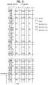
- FIG. 2 is a diagram illustrating structures of a control plane and a user plane of a radio interface protocol between a user equipment and E-UTRAN based on the 3GPP radio access network standard.
- the control plane means a passageway where control messages are transmitted, wherein the control messages are used by the user equipment and the network to manage call.
- the user plane means a passageway where data generated in an application layer, for example, voice data or Internet packet data are transmitted.
- a physical layer as the first layer provides an information transfer service to an upper layer using a physical channel.
- the physical layer is connected to a medium access control (MAC) layer via a transport channel, wherein the medium access control layer is located above the physical layer.
- Data are transferred between the medium access control layer and the physical layer via the transport channel.
- Data are transferred between one physical layer of a transmitting side and the other physical layer of a receiving side via the physical channel.
- the physical channel uses time and frequency as radio resources.
- the physical channel is modulated in accordance with an orthogonal frequency division multiple access (OFDMA) scheme in a downlink, and is modulated in accordance with a single carrier frequency division multiple access (SC-FDMA) scheme in an uplink.
- OFDMA orthogonal frequency division multiple access
- SC-FDMA single carrier frequency division multiple access
- a medium access control (MAC) layer of the second layer provides a service to a radio link control (RLC) layer above the MAC layer via a logical channel.
- the RLC layer of the second layer supports reliable data transmission.
- the RLC layer may be implemented as a functional block inside the MAC layer.
- PDCP packet data convergence protocol
- a radio resource control (RRC) layer located on the lowest part of the third layer is defined in the control plane only.
- the RRC layer is associated with configuration, re-configuration and release of radio bearers ('RBs') to be in charge of controlling the logical, transport and physical channels.
- the RB means a service provided by the second layer for the data transfer between the user equipment and the network.
- the RRC layers of the user equipment and the network exchange RRC message with each other. If the RRC layer of the user equipment is RRC connected with the RRC layer of the network, the user equipment is in an RRC connected mode. If not so, the user equipment is in an RRC idle mode.
- a non-access stratum (NAS) layer located above the RRC layer performs functions such as session management and mobility management.
- NAS non-access stratum
- One cell constituting a base station eNB is set to one of bandwidths of 1.25, 2.5, 5, 10, 15, and 20MHz and provides a downlink or uplink transmission service to several user equipments. At this time, different cells may be set to provide different bandwidths.
- a broadcast channel carrying system information
- a paging channel carrying paging message
- a downlink shared channel carrying user traffic or control messages.
- Traffic or control messages of a downlink multicast or broadcast service may be transmitted via the downlink SCH or an additional downlink multicast channel (MCH).
- a random access channel carrying an initial control message and an uplink shared channel (UL-SCH) carrying user traffic or control message.
- BCCH broadcast control channel
- PCCH paging control channel
- CCCH common control channel
- MCCH multicast control channel
- MTCH multicast traffic channel
- FIG. 3 is a diagram showing physical channels used in a 3GPP system and a general signal transmission method using the same.
- a UE performs an initial cell search operation such as synchronization with an eNB when power is turned on or the UE enters a new cell (S301).
- the UE may receive a Primary Synchronization Channel (P-SCH) and a Secondary Synchronization Channel (S-SCH) from the eNB, perform synchronization with the eNB, and acquire information such as a cell ID. Thereafter, the UE may receive a physical broadcast channel from the eNB so as to acquire broadcast information within the cell.
- the UE may receive a Downlink Reference Signal (DL RS) so as to check a downlink channel state in the initial cell search operation.
- DL RS Downlink Reference Signal
- the UE which completes the initial cell search may receive a Physical Downlink Control Channel (PDCCH) and a Physical Downlink Shared Channel (PDSCH) according to information included in the PDCCH so as to acquire more detailed system information (S302).
- PDCH Physical Downlink Control Channel
- PDSCH Physical Downlink Shared Channel
- the UE may perform a Random Access Procedure (RACH) on the eNB (S303 to S306).
- RACH Random Access Procedure
- the UE may transmit a specific sequence as a preamble through a Physical Random Access Channel (PRACH) (S303 and S305) and receive a response message of the preamble through the PDCCH and the PDSCH corresponding thereto (S304 and S306).
- PRACH Physical Random Access Channel
- a contention resolution procedure may be further performed.
- the UE which performs the above procedures may perform PDCCH/PDSCH reception (S307) and Physical Uplink Shared Channel (PUSCH)/Physical Uplink Control Channel (PUCCH) transmission (S308) as a general uplink/downlink signal transmission procedure.
- the UE may receive Downlink Control Information (DCI) through the PDCCH.
- DCI Downlink Control Information
- the DCI may include control information such as resource allocation information for the UE.
- Different DCI formats are defined according to different usages of DCI.
- Control information that the UE transmits to the eNB on the uplink or receives from the eNB on the downlink includes a downlink/uplink ACKnowledgment/Negative ACKnowledgment (ACK/NACK) signal, a Channel Quality Indicator (CQI), a Precoding Matrix Index (PMI), a Rank Indicator (RI), etc.
- ACK/NACK downlink/uplink ACKnowledgment/Negative ACKnowledgment
- CQI Channel Quality Indicator
- PMI Precoding Matrix Index
- RI Rank Indicator
- the UE may transmit control information such as the aforementioned CQI/PMI/RI on a PUSCH and/or a PUCCH.
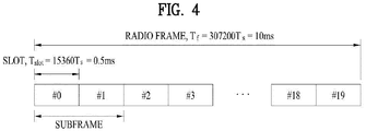
- FIG. 4 is a diagram illustrating a structure of a radio frame used in the LTE system.
- a radio frame is 10ms (327200xT s ) long and divided into 10 equal-sized subframes. Each subframe is 1ms long and further divided into two slots. Each time slot is 0.5ms (15360xT s ) long.
- a slot includes a plurality of OFDM symbols in the time domain and a plurality of Resource Blocks (RBs) in the frequency domain. In the LTE system, one RB includes 12 subcarriers by 7 (or 6) OFDM symbols.
- a unit time in which data is transmitted is defined as Transmission Time Interval (TTI).
- TTI Transmission Time Interval
- the TTI may be defined as one or more subframes.
- the above-described radio frame structure is purely exemplary and thus the number of subframes in a radio frame, the number of slots in a subframe, or the number of OFDM symbols in a slot may vary.
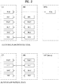
- FIG. 5 is a diagram illustrating an exemplary control channel included in the control region of a subframe in a downlink radio frame.
- a subframe includes 14 OFDM symbols.
- the first one to three OFDM symbols of a subframe are used for a control region and the other 13 to 11 OFDM symbols are used for a data region according to a subframe configuration.
- reference characters R1 to R4 denote RSs or pilot signals for antenna 0 to antenna 3.
- RSs are allocated in a predetermined pattern in a subframe irrespective of the control region and the data region.
- a control channel is allocated to non-RS resources in the control region and a traffic channel is also allocated to non-RS resources in the data region.
- Control channels allocated to the control region include a Physical Control Format Indicator Channel (PCFICH), a Physical Hybrid-ARQ Indicator Channel (PHICH), a Physical Downlink Control Channel (PDCCH), etc.
- PCFICH Physical Control Format Indicator Channel
- PHICH Physical Hybrid-ARQ Indicator Channel
- PDCCH Physical Downlink Control Channel
- the PCFICH is a physical control format indicator channel carrying information about the number of OFDM symbols used for PDCCHs in each subframe.
- the PCFICH is located in the first OFDM symbol of a subframe and configured with priority over the PHICH and the PDCCH.
- the PCFICH is composed of 4 Resource Element Groups (REGs), each REG being distributed to the control region based on a cell Identity (ID).
- REG includes 4 Resource Elements (REs).
- An RE is a minimum physical resource defined by one subcarrier by one OFDM symbol.
- the PCFICH indicates 1 to 3 or 2 to 4 according to a bandwidth.
- the PCFICH is modulated in Quadrature Phase Shift Keying (QPSK).
- QPSK Quadrature Phase Shift Keying
- the PHICH is a physical Hybrid-Automatic Repeat and request (HARQ) indicator channel carrying an HARQ ACK/NACK for an uplink transmission. That is, the PHICH is a channel that delivers DL ACK/NACK information for UL HARQ.
- the PHICH includes one REG and is scrambled cell-specifically.
- An ACK/NACK is indicated in one bit and modulated in Binary Phase Shift Keying (BPSK).
- BPSK Binary Phase Shift Keying
- the modulated ACK/NACK is spread with a Spreading Factor (SF) of 2 or 4.
- SF Spreading Factor
- a plurality of PHICHs mapped to the same resources form a PHICH group.
- the number of PHICHs multiplexed into a PHICH group is determined according to the number of spreading codes.
- a PHICH (group) is repeated three times to obtain a diversity gain in the frequency domain and/or the time domain.
- the PDCCH is a physical downlink control channel allocated to the first n OFDM symbols of a subframe.
- n is 1 or a larger integer indicated by the PCFICH.
- the PDCCH is composed of one or more CCEs.
- the PDCCH carries resource allocation information about transport channels, PCH and DL-SCH, an uplink scheduling grant, and HARQ information to each UE or UE group.
- the PCH and the DL-SCH are transmitted on a PDSCH. Therefore, an eNB and a UE transmit and receive data usually on the PDSCH, except for specific control information or specific service data.
- Information indicating a UE (one or more UEs) to receive PDSCH data and information indicating how the UEs are supposed to receive and decode the PDSCH data are delivered on a PDCCH.
- a UE one or more UEs
- information indicating how the UEs are supposed to receive and decode the PDSCH data are delivered on a PDCCH.
- CRC Cyclic Redundancy Check
- RNTI Radio Network Temporary Identity
- a transport block size, a modulation scheme, coding information, etc.) "C" is transmitted in a specific subframe, a UE within a cell monitors, that is, blind-decodes a PDCCH using its RNTI information in a search space. If one or more UEs have RNTI "A”, these UEs receive the PDCCH and receive a PDSCH indicated by "B” and "C” based on information of the received PDCCH.
- FIG. 6 is a diagram illustrating a structure of an uplink subframe in the LTE system.
- an uplink subframe may be divided into a region to which a Physical Uplink Control Channel (PUCCH) for delivering control information is allocated and a region to which a Physical uplink Shared Channel (PUSCH) for delivering user data is allocated.
- the middle of the subframe is allocated to the PUSCH, while both sides of the data region in the frequency domain are allocated to the PUCCH.
- PUCCH Physical Uplink Control Channel
- PUSCH Physical uplink Shared Channel
- Control information transmitted on the PUCCH may include a Hybrid Automatic Repeat reQuest ACKnowledgement/Negative ACKnowledgement (HARQ ARCK/NACK), a Channel Quality Indicator (CQI) representing a downlink channel state, a Rank Indicator (RI) for Multiple Input Multiple Output (MIMO), a Scheduling Request (SR) requesting uplink resource allocation.
- HARQ ARCK/NACK Hybrid Automatic Repeat reQuest ACKnowledgement/Negative ACKnowledgement
- CQI Channel Quality Indicator
- RI Rank Indicator
- MIMO Multiple Input Multiple Output
- SR Scheduling Request
- a PUCCH for one UE may use one Resource Block (RB) that occupies different frequencies in each slot of a subframe. That is, the two RBs allocated to the PUCCH frequency-hop over the slot boundary of the subframe.
- MIMO Multiple Input Multiple Output
- Tx Transmission
- Rx Reception
- MIMO can increase capacity and improve performance in a wireless communication system.
- Tx Transmission
- Rx Reception
- MIMO can increase capacity and improve performance in a wireless communication system.
- MIMO is interchangeable with "multi-antenna”.
- the MIMO technology does not depend on a single antenna path to receive a whole message. Rather, it completes the message by combining data fragments received through a plurality of antennas.
- MIMO can increase data rate within a cell area of a predetermined size or extend system coverage at a given data rate.
- MIMO can find its use in a wide range including mobile terminals, relays, etc.
- MIMO can overcome a limited transmission capacity encountered with the conventional single-antenna technology in mobile communication.
- FIG. 7 is a diagram illustrating a configuration of a typical MIMO communication system.
- a transmitter has N T Tx antennas and a receiver has N R Rx antennas.
- the simultaneous use of a plurality of antennas at both the transmitter and the receiver increases a theoretical channel transmission capacity, compared to use of a plurality of antennas at only one of the transmitter and the receiver.
- the channel transmission capacity increases in proportion to the number of antennas. Therefore, transmission rate and frequency efficiency are increased.
- R o that may be achieved with a single antenna
- the transmission rate may be increased, in theory, to the product of R o and a transmission rate increase rate R i in the case of multiple antennas.
- R i is the smaller value between N T and N R .
- R i min N T N R
- a MIMO communication system with four Tx antennas and four Rx antennas may achieve a four-fold increase in transmission rate theoretically, relative to a single-antenna system. Since the theoretical capacity increase of the MIMO system was verified in the middle 1990s, many techniques have been actively proposed to increase data rate in real implementation. Some of the techniques have already been reflected in various wireless communication standards for 3G mobile communications, future-generation Wireless Local Area Network (WLAN), etc.
- WLAN Wireless Local Area Network
- a different transmission power may be applied to each piece of transmission information, S 1 , S 2 , ... , S N T .
- the transmission power-controlled transmission information vector is given as Equation 3 below.
- N T transmission signals x 1 , x 2 , ... , x N T may be generated by multiplying the transmission power-controlled information vector ⁇ by a weight matrix W .
- the weight matrix W functions to appropriately distribute the transmission information to the Tx antennas according to transmission channel states, etc.
- These N T transmission signals x 1 , x 2 ,..., x N T are represented as a vector x , which may be determined by [Equation 5].
- w ij denotes a weight between a j th piece of information and an i th Tx antenna and W is referred to as a weight matrix or a precoding matrix.
- the rank of a channel matrix is the maximum number of different pieces of information that can be transmitted on a given channel, in its physical meaning. Therefore, the rank of a channel matrix is defined as the smaller between the number of independent rows and the number of independent columns in the channel matrix. The rank of the channel matrix is not larger than the number of rows or columns of the channel matrix.
- the rank of a channel matrix H , rank ( H ) satisfies the following constraint. rank H ⁇ min N T N R
- a different piece of information transmitted in MIMO is referred to as 'transmission stream' or shortly 'stream'.
- the 'stream' may also be called 'layer'. It is thus concluded that the number of transmission streams is not larger than the rank of channels, i.e. the maximum number of different pieces of transmittable information.
- the channel matrix H is determined by Equation 7 below. # of streams ⁇ rank H ⁇ min N T N R
- One or more streams may be mapped to a plurality of antennas in many ways.
- the stream-to-antenna mapping may be described as follows depending on MIMO schemes.
- one stream is transmitted through a plurality of antennas, this may be regarded as spatial diversity.
- this may be spatial multiplexing.
- a hybrid scheme of spatial diversity and spatial multiplexing in combination may be contemplated.
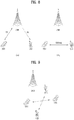
- FIG. 8 is a diagram for conceptual explanation of D2D communication.
- FIG. 8(a) illustrates a typical eNB-centered communication scheme.
- a first UE UE1 may transmit data to an eNB on the uplink and the eNB may transmit the data from the first UE UE1 to a second UE UE2 on the downlink.
- FIG. 8(b) illustrates a UE-to-UE communication scheme as an example of D2D communication.
- Data exchange between UEs may be performed without going through an eNB.
- a link established directly between devices may be referred to as a D2D link.
- the D2D communication reduces latency and requires less radio resources, compared to the typical eNB-centered communication scheme.
- D2D communication is a scheme for supporting communication between devices (or UEs) without going through an eNB.
- D2D communication needs to reuse resources of a typical wireless communication system (e.g., 3GPP LTE/LTE-A) and, thus, should not cause interference or jamming in the typical wireless communication system.
- a typical wireless communication system e.g., 3GPP LTE/LTE-A
- the present invention proposes a coding scheme for reducing interference between a plurality of transmission UEs during repetitive transmission of the same information every resource unit using a plurality of resources in D2D communication.
- an entire time-frequency region in which D2D communication is performed is referred to as a resource pool and a minimum unit composed of time and frequency for transmission in the resource pool is defined as a resource element (RE).
- a unit as one group formed by collecting a plurality of REs is defined as a D2D resource subframe.
- the D2D resource subframe may be a small group in a current LTE subframe or may be one unit formed by collecting a plurality of LTE subframes.
- the present invention may be applied to a case in which the same information is repeatedly transmitted through a plurality of D2D resource sub frames in the resource pool.
- a reference signal (RS) and data may be representatively transmitted.
- FIG. 9 is a reference diagram for explanation of a case in which D2D communication is performed in an environment in which a plurality of UEs is present according to the present invention.
- D2D communication is performed as illustrated in FIG. 9
- two UEs may frequently perform transmission on each other through the same D2D resource subframe.
- reference signals (RSs) and data of the UEs may collide with each other, thereby degrading overall system performance.
- the present invention proposes a method of applying codes orthogonal to repeated D2D resource subframes in order to reduce interference due to transmission UEs when information is repeatedly transmitted tin a plurality of D2D resource subframes such that two or more D2D UEs use low power.
- reference signals and data may be arranged to form a predetermined pattern in each D2D resource subframe.
- N the number of repeated D2D resource subframes
- a transmitted RS is a i ( n ), k,l
- data is d i( n ), k,l .
- i ( n ) is a number of n th repeated D2D resource subframes
- k is a frequency number of a resource element (RE) in the n th repeated D2D resource subframes
- l is an OFDM symbol index of a resource element in the n th repeated D2D resource subframes.
- a i ( n ), k , l and d i ( n ) ,k,l are the same information and are scrambled signals with respect to all n (i.e., 1 ⁇ N ).
- one sequence needs to be selected for scrambling in a D2D resource subframe.
- D2D transmission may interfere with each other in the same D2D resource subframe, it may be necessary to different scrambling sequences every transmission UE for interference randomization.
- a reception UE may simultaneously receive RSs of the three transmission UEs but only one transmission UE among these may transmit information for the reception UE.
- interference may increase from an RS point of view. Accordingly, in order to overcome this problem, transmission UEs need to set a scrambling sequence to be randomly selected for interference randomization.
- the present invention proposes that a scrambling sequence that is randomly selected in a first D2D resource subframe among repeated D2D resource subframes be used in the same way in different repeated D2D resource subframes when the same information is repeatedly transmitted in a plurality of D2D resource subframes to a specific transmission UE.
- the scrambled a i ( n ), k,l may apply orthogonal codes as shown in Equation 8 below.
- Equation 8 ( nm ) indicates an element of ( n,m ) in a matrix D .
- an RS to which orthogonal codes are applied may be represented according to Equation 9 below.
- a transmission UE may transmit a i ( n ), k , l to which the code is applied for an RS.
- m may be selected from 1 ⁇ N and may be randomly selected every transmission UE or may be selected and indicated by a representative UE or eNB.
- the representative UE may refer to a specific UE selected from a group including a plurality of UEs.
- a transmission UE may dynamically notify a reception UE of m through DCI format or may semi-statically notify the reception UE via RRC signaling.
- Equation 9 an example of an orthogonal code for N repeated subframes has been described in terms of Equation 9 above, the present invention may also be applied to a case in which another orthogonal code is used instead of D nm N ⁇ N , needless to say.
- an RS to which Equation 9 above is applied may apply interference randomization to interference between transmission UEs, thereby reducing an interference effect.
- D2D resource subframes in which interference channels are repeated are similar to each other, inference may be almost removed by an orthogonal code.
- scrambled d i ( n ), k,l may be represented according to Equation 10 below by applying the orthogonal code of Equation 8 above.
- d ⁇ i n , k , l d i n , k , l ⁇ D nm ′ N ⁇ N
- the present invention proposes that a scrambling sequence that is randomly selected in a first D2D resource subframe of D2D resource subframes that are repeatedly arranged in a specific UE should be used in the same way in different repeated D2D resource subframes.
- a transmission UE may transmit d i ( n ), k,l to which the code is applied for an RS.
- m ' may be selected from 1 ⁇ N and may be randomly selected every transmission UE or may be selected and indicated by a representative UE or eNB.
- the transmission UE may dynamically notify a reception UE of m ' through DCI format or may semi-statically notify the reception UE via RRC signaling.
- the reception UE may receive a received signal represented according to Equation 11 below through one resource element (RE).
- RE resource element
- r i ( n ) , k , l h i ( n ) , k , l d ⁇ i ( n ) , k , l + ⁇ u ( h u i ( n ) , k , l d ⁇ u i ( n ) , k , l ) + n i ( n ) , k , l
- index u refers to an index of a UE that transmits interference.
- a reciprocal of D nm ′ N ⁇ N may be multiplied.
- signals y i ( n ) ,k,l obtained by descrambling N signals with the same index k,l among signals Z i ( n ) ,k,l of Equation 12 above may be collected and represented to derive Equation 13 below.
- index k,l is omitted and Equation 13 below is represented.
- Equation 13 with regard to desired information d , the same scramble is applied to the same data and only D nm ′ N ⁇ N of Equation 10 above is differently applied and, thus, the same information may remain in N resource elements REs and a representative value may be represented by d.
- u d may be data of different transmission UEs that perform transmission using the same D2D resource subframe with index u to cause interference and uses the same scrambling and, thus, the same phase is just changed during descrambling of a desired signal.
- a different code D n u m ′ N ⁇ N from D nm ′ N ⁇ N of Equation 10 above is applied and, thus, an interference channel may be represented according to Equation 13 below.
- y h H h d + h H ⁇ u H u d u + h H n
- Equation 14 an interference part may be extracted to obtain Equation 15 below.
- I h i 1 h i 2 ⁇ h i N H ⁇ u h i 1 u D 1 m ′ N ⁇ N D 1 m u ′ N ⁇ N h i 2 u D 2 m ′ N ⁇ N D 2 m u ′ N ⁇ N ⁇ h i N u D Nm ′ N ⁇ N D Nm u ′ N ⁇ N d u
- Equation 14 above when a desired channel and an interference channel are almost similar to each other between repeated D2D resource subframes, I may be approximately '0'. This is because D nm ′ N ⁇ N and D n u m ′ N ⁇ N are orthogonal to each other. Even if channels are not completely the same, when adjacent subframes are used, it may be expected that interference may be significantly reduced.
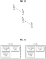
- FIG. 10 is a reference diagram for explanation of the aforementioned effect obtained by applying the present invention.
- UE 1, UE 2, UE 3, and UE 4 may be D2D UEs that are synchronized with one another.
- the UE 1 transmits an RS or data to the UE 2
- the UE 4 may intend to transmit an RS or data to the UE 3.
- the UE 4 is spaced far from the UE 1 and does not recognize that that UE 1 performs transmission and, thus, the UE4 may begin to perform transmission through a resource location being used by the UE 1.
- a transmitted signal of the UE 1 and a transmitted signal of the UE 4 may be considered as interference in terms of the UE 3 and the UE 2.
- the UE 2 and the UE 3 may receive a signal with significantly reduced interference.
- code D nm ′ N ⁇ N other than scramble is separately applied has been described according to the present invention for convenience of description, code D nm ′ N ⁇ N may be simultaneously applied through one scramble.
- an RS and data may be simultaneously applied but only one of these may be applied.
- Equations 9 and 10 above may be simultaneously applied.
- m and m ' may use the same value and the same orthogonal sequence may be applied.
- transmission UEs may use a i ( n ) ,k,l obtained by applying an orthogonal corresponding to Equation 9 above to a scrambling sequence a i ( n ), k,l as a base for an RS as a scrambling sequence for an RS.
- d i ( n ), k,l obtained by applying an orthogonal code corresponding to Equation 10 above to a scrambling sequence d i( n ), k,l as a base for data may be used as a scrambling sequence for data.
- a scrambling sequence selected from a first D2D resource subframe among repeated D2D resource subframes may be used in the same way in different repeated D2D resource subframes.
- data scrambling for uplink in the LTE is defined according to Table 1 below in 5.3.1 'Scrambling' of the 3GPP TS 36.211 document.
- b ( q ) ( i ) is a coded bit of data and c ( q ) (i) is a scrambling sequence.
- b ( q ) ( i ) and c ( q ) ( i ) may be combined to constitute a scrambled coded bit b ⁇ ( q ) ( i ).
- d i ( n ), k,l described according to the present invention may be considered as symbol data obtained by modulating a scrambled coded bit b ⁇ ( q ) ( i ) and then performing layer mapping.
- a scrambling sequence selected from a first D2D resource subframe among repeated D2D resource subframes may be used in the same way in different repeated D2D resource subframes. Accordingly, when c init is generated based on a scrambling sequence generating method for PUSCH transmission in the current LTE system, one method may be used in each of the following two situations.
- c init may be generated according to Equation 16 below in each situation.
- N ID Cluster may refer to a group ID when a D2D cluster uses the group ID or refer to an ID of a transmission UE.
- N ID Cluster may be fixed to '0' and then used. That is, fixing of N ID Cluster to '0' means that N ID Cluster is removed from Equation 16 above.
- n RX may refer to an ID of a reception UE or an ID of a transmission UE. Alternatively, this value may be set to be fixed to '0' and then used. Fixing of n RX to '0' means that a factor including n RX is removed from Equation 16 above.
- Equation 16 above q refers to an index of a codeword. However, in the present invention, when only 1 layer transmission is used in D2D communication, q may be set to be fixed to '0'.
- ⁇ may be determined as a value obtained by rounding up log 2 N clusterid ( N clusterid is a total number of N ID Cluster ). When N ID Cluster is set to be fixed to '0', a value of N clusterid may be '1'.
- ⁇ may be determined as a value + ⁇ obtained by rounding up log 2 N s .
- N s is defined as a total number of ⁇ n first 2 ⁇ in Equation 15 related to the situation A, is defined as a total number of ⁇ n s ⁇ 2 N offset 2 N ⁇ in an equation related to the situation A-1, and is defined as a total number of N g in an equation related to the situation B.
- ⁇ may be defined as ⁇ +1 in a system using a maximum 2 codeword like the current LTE system.
- ⁇ may be used as the same value as ⁇ . That is, ⁇ , ⁇ , and ⁇ may be determined such that c init does not overlap between UEs that perform transmission.
- d i ( n ), k , l obtained by applying an orthogonal code to a symbol d i( n ), k,l , which is formed via scrambling with c init , modulation, and layer mapping, according to Equation 10 above may be generated.
- an ID of a transmission UE an ID of a reception UE, a cluster ID, and a subframe number may be used as an initial ID for the scrambling sequence.
- a reception UE it may be difficult for a reception UE to know an ID of a transmission UE or a cluster ID or an ID of the reception UE may not be required because the transmission UE is broadcasting the ID. In this case, burden imposed to a reception UE may be excessively increased when both an ID of a transmission UE and a cluster ID are monitored and detected.
- Equation 10 represents a cyclic shift value of an RS and an orthogonal code value according to the present invention.
- a cyclic shift value may be defined as shown in Table 2 below with reference to paragraph '5.5.2.1.1' of TS 36.211 as the LTE standard document.
- n DMRS 1 is given by Table 5.5.2.1.1-2 according to the parameter cydicShift provided by higher layers
- n DMRS , ⁇ 2 is given by the cyclic shift for DMRS field in most recent uplink-related DCI3GPP TS 36.212[3] for the transport block associated with the corresponding PUSCH transmission where the value of n DMRS , ⁇ 2 is given in Table 5.5.2.1.1-1.
- a value of the initial ID may become diversified and, thus, this may help interference randomization in terms of data.
- a data scrambling sequence is determined according to a cyclic shift value.
- the cyclic shift value and the orthogonal code value may be added to an initial ID as follows.
- the reception UE may know an orthogonal code D nm N ⁇ N of an RS via blind detection or signaling by a transmission UE.
- the reception UE may know the orthogonal code D nm N ⁇ N using a predetermined value. That is, the reception UE may determine m through this procedure.
- the reception UE may use a cyclic shift value n cs , ⁇ and an orthogonal code m' which are obtained during estimation of an RS in order to obtain an initial ID of a scrambling sequence applied to data.
- a DMRS may be generated according to a common ID in order to detect a D2D signal irrespective of a network to which each UE belongs, but when a DMRS sequence is common (i.e., when each D2D UE randomly transmits a D2D signal), if a plurality of UEs use the same resource region, performance may be degraded due to collision between DMRSs. In order to prevent this, cyclic shift of the same sequence may be considered.
- scrambling of data may be considered and data scrambling may also be differently set in a D2D pair to randomize interference.
- the present invention proposes that a scrambling sequence used in a data region and a Cyclic Shift Value (CS value) should be associated with each other and determined.
- CS value Cyclic Shift Value
- an orthogonal code may be considered in one form of a scrambling sequence of a data region and, in this case, may perform a function of repetition as well as a function of scrambling.
- a transmission UE may determine a cyclic shift value of a DMRS and determine an index (e.g., m') of an orthogonal code to be used in scrambling of a data region using the corresponding cyclic shift value.
- a cyclic shift value is selected from 0 to 11 and a spreading factor of an orthogonal code is 4 (a repetition factor may be interpreted to be 4, for example, CS value%4 may be used as an index of an orthogonal code to be used in scrambling of a data region may be used.
- the orthogonal code may spread a modulated symbol.
- scrambling at a bit level prior to modulation may be considered for interference randomization between repetition resource units and, as described above, bit level scrambling initialization determined according to a DMRS cyclic shift value, an orthogonal code index, and so on may be performed.
- an initialization parameter of a scrambling sequence may be determined according to a DMRS cyclic shift value.
- a value obtained by adding DMRS cyclic shift value * X to the corresponding seed may be used as a final scrambling sequence initialization parameter (here, X prevents a final initial parameter and another initial seed from overlapping.).
- repetition may be considered in order to enhanced decoding performance of a D2D signal and, in this regard, a slot index (or a subframe index) or the like may be added to scrambling sequence initialization during repetition so as to additionally randomize interference in a D2D pair with the same repeated resources.
- a cyclic shift value may be implicitly associated in another form of a scrambling sequence of a data region.
- a specific parameter Y may be used to determine a scrambling sequence of a data region and simultaneously used to determine a cyclic shift value of a DMRS. That is, the specific parameter Y is used to determine both the scrambling sequence of the data region and the cyclic shift value of the DMRS and, thus, it may be deemed that the scrambling sequence and the cyclic shift value of the DMRS are implicitly associated with each other.
- a representative example of the parameter Y may be an ID of a D2D transmission UE or an ID of synchronized UE.
- the parameter Y may be an ID of a D2D reception UE.
- An ID of a reception UE may be referred to as a SA ID as a scheduling assignment ID in the current LTE.
- a set (hereinafter, set A for convenience of description) including at least parameter or all parameters from ⁇ D2D Tx UE ID, SS ID, data subframe number, SA sub frame number, and number of data subframes ⁇ .
- the D2D Tx UE ID may be an ID of a UE that performs transmission in D2D
- the SS ID may be a sequence ID of D2DSS or a synchronization signal ID included in PD2DSCH
- the data subframe number may be a number of a subframe in which data is transmitted in a D2D communication resource.
- the SA subframe number may refer to a number of a subframe in which a transmission UE performs scheduling assignment. When scheduling assignment is performed in a plurality of subframes, the SA subframe may refer to one of the subframes.
- the number of data subframes may refer to the number of subframes used to transmit data.
- a resource pattern type (RPT) used in data may also be considered for a scrambling sequence of a data region.
- RPT resource pattern type
- D2D has been discussed for a method of indicating a type of a resource pattern indicating a detailed position of data in scheduling assignment.
- a scrambling sequence of a data region may be formed as a function.
- D2D reception UE ID may also be used for the scrambling sequence of the data region.
- Equation 17 When a scrambling sequence of a data region for D2D communication according to the present invention is defined based on a configuration of a scrambling sequence of a PUSCH used in uplink on the LTE system, Equation 17 below may be defined in order to determine a initial value c init of the scrambling sequence of the data region.
- c init TXID ⁇ 2 ⁇ 1 + SFNM ⁇ 2 ⁇ 2 + SSID ⁇ 2 ⁇ 3
- SSID is a SS ID of a set A
- SFNM is a data subframe number in the set A
- TXID is a D2D Tx UE ID in the set A.
- ⁇ i may be set such that c init has a different value. Accordingly, the set A may be determined using at least one of Methods A-1 to A-3-11 below.
- a method of determining a cyclic shift value of a DMRS for D2D communication will be described.
- a set (hereinafter, the set B) including at least some of parameters of ⁇ D2D Tx UE ID, SS ID, data subframe number, SA subframe number, and number of data subframes ⁇ may be used.
- the D2D Tx UE ID may be an ID of a UE that performs transmission in D2D
- the SS ID may be a sequence ID of D2DSS or a synchronization signal ID included in a PD2DSCH
- the data subframe number may be a number of a subframe in which data is transmitted in a D2D communication resource.
- the SA subframe number may be a number of a subframe in which a Tx UE performs scheduling assignment. When scheduling assignment is performed in a plurality of subframes, the SA subframe may be one of these.
- the number of data subframes may be the number of subframes used to transmit data.
- an RPT used in data may also be considered for a cyclic shift value of a DMRS.
- the possibility that a type of a resource pattern indicating a detailed position of data is indicated via scheduling assignment may be high.
- a cyclic shift value of a DMRS may be formed as a function of an RPT.
- a D2D reception UE ID may also be considered for a cyclic shift value of a DMRS.
- n cs TXID + SFNM + SSID mod 12
- SSID is a SS ID of a set B
- SFNM is a data subframe number in the set B
- TXID is a D2D Tx UE ID in the set B.
- Methods B-1 to B-3-9 below may be applied in order to determine a cyclic shift value of a DMRS for D2D communication according to the present invention.
- n cs, ⁇ in Equation 19 above may be determined according to Equation 20 blow.
- n cs , ⁇ n DMRS 1 + n DMRS , ⁇ 2 + n PN n s mod 12
- n DMRS 1 may be indicated via high layer signaling
- a value of n DMRS , ⁇ 2 may be received from DCI and a value of n PN ( n s ) may be determined according to Equation 21 below.
- Equation 21 a value of c init for c ( i ) may be determined according to Equation 22 below.
- c init ⁇ N ID cell 30 ⁇ ⁇ 2 5 + N ID cell + ⁇ ss mod 30
- a value of N ID cell may be a cell ID and ⁇ ss may be a value indicated by a high layer. Accordingly, in Method B-3 according to the present invention, at least one of Methods B-3-1 to B-3-9 below may be applied to Equations 19 to 22 above to determine a cyclic shift value of a D2D DMRS.
- the cyclic shift value of the DMRS of a data region may be generated using a D2D Tx UE ID.
- the cyclic shift value of the DMRS of a data region may be generated using a D2D Tx UE ID and may be hopped using a data subframe number or a data slot number.
- the hopping pattern may be initialized whenever a period of a data region is started (e.g., a start point of 40 ms when a data region has a period of 40 ms).
- a hopping portion needs to be re-configured every current slot number. In other words, a frame number needs to also be considered during reconfiguration of the hopping pattern.
- the cyclic shift value of the DMRS of a data region may be generated using a D2D Tx UE ID and a subframe number and a subframe number may be generated using a fixed value.
- the method may be based on a method of applying an OCC value in a configuration of a DMRS used in uplink on the current LTE.
- a partial set including at least one of parameters of ⁇ D2D Tx UE ID, SS ID, data subframe number, SA subframe number, and number of data subframes ⁇ may be used in order to determine an OCC value [ w ( ⁇ ) (0) w ( ⁇ ) (1)] ( ⁇ is a layer number but a single layer is assumed in D2D and, thus, ⁇ will be omitted from indexes hereinafter.) of a DMRS.
- D2D Tx UE ID may be an ID of a UE that performs transmission in D2D
- SS ID may be a sequence ID of D2DSS or a synchronization signal ID included in a PD2DSCH
- a data subframe number may be a number of a subframe in which data is transmitted in a D2D communication resource.
- the SA subframe number may be a number of a subframe in which a Tx UE performs scheduling assignment. When scheduling assignment is performed in a plurality of subframes, the SA subframe may refer to one of the subframes.
- the number of data subframes may refer to the number of subframes used to transmit data.
- an RPT used in data may also be used for an OCC value of a DMRS.
- D2D has been discussed for a method of indicating a type of a resource pattern indicating a detailed position of data in scheduling assignment.
- interference randomization may be required in the overlapping portions.
- an OCC value of a DMRS may be determined using an RPT.
- the D2D reception UE ID may also be considered for an OCC value of a DMRS.
- SSID may be an SS ID in a set C
- SFNM may be a data subframe number in the set C
- TXID may be a D2D Tx UE ID in the set C.
- An OCC value of a DMRS may be determined by applying at least one of Methods C-1 to C-6 to be described below.
- the OCC value of the DMRS of a data region may be generated using a D2D Tx UE ID.
- the OCC value of the DMRS of a data region may be generated using a D2D Tx UE ID and may be hopped using a data subframe number or a data slot number.
- the hopping pattern may be initialized whenever a period of a data region is started (e.g., a start point of 40 ms when a data region has a period of 40 ms).
- the OCC value of the DRMS of a data region may be generated using a subframe number of a D2D Tx UE ID and a subframe number may be generated using a fixed value.
- a cyclic shift value and OCC value of a DMRS may be collectively determined.
- the cyclic shift value and the OCC value may be collectively determined from a specific set among sets (e.g., (CS, OCC): ⁇ (1,3), (2,5), (7,1),... ⁇ ) set with a predetermined value.
- the set may be preconfigured or set via RRC signaling.
- a set (hereinafter, the set D) including at least one of parameters of ⁇ D2D Tx UE ID, SS ID, data subframe number, SA subframe number, and number of data subframes ⁇ may be used.
- D2D Tx UE ID may be an ID of a UE that performs transmission in D2D
- SS ID may be a sequence ID of D2DSS or a synchronization signal ID included in a PD2DSCH
- a data subframe number may be a number of a subframe in which data is transmitted in a D2D communication resource.
- the SA subframe number may be a number of a subframe in which Tx UE performs scheduling assignment. When scheduling assignment is performed in a plurality of subframes, the SA subframe may be one subframe among theses.
- the number of data subframes may be the number of subframes used to transmit data.
- the cyclic shift value and the OCC value may be hopped using a data subframe number or a data slot number.
- the hopping pattern may be initialized whenever a period of a data region is started (e.g., a start point of 40 ms when a data region has a period of 40 ms).
- a hopping portion needs to be corrected every current slot number. In other words, a frame number needs to also be considered during reconfiguration of the hopping pattern.
- a method of determining a base sequence of a DMRS according to the present invention will be described.
- a root value of a zadoff-chu sequence may be changed using group hopping and sequence hopping to generate the base sequence of the DMRS.
- group hopping and sequence hopping values may be determined according to a slot number and an ID of a serving cell.
- a set including at least one of parameters of ⁇ D2D Tx UE ID, SS ID, data slot number, SA subframe number, and number of data subframes ⁇ may be used.
- D2D Tx UE ID may be an ID of a UE that performs transmission in D2D
- SS ID may be a sequence ID of D2DSS or a synchronization signal ID included in a PD2DSCH
- the data slot number may be a number of a slot in which data is transmitted in a D2D communication resource.
- the SA subframe number may be a number of a subframe in which a Tx UE performs scheduling assignment.
- the SA subframe may be one subframe among theses.
- the number of data subframes may be the number of subframes used to transmit data.
- an RPT used in data may also be considered for a base sequence of a DMRS.
- whether to indicate a type of a resource pattern indicating a detailed position of a data during scheduling assignment has been discussed.
- a base sequence of a DMRS may be generated according to an RPT.
- D2D reception UE ID may also be used for the base sequence of the DMRS.
- Methods D-1 to D-3-13 may be applied.
- Equation 23 a value of q as a root value may be determined according to Equation 24 below.
- Equation 24 a value of u may be determined according to Equation 25 below.
- u f gh n s + f ss mod 30
- a value of f gh ( n s ) may be determined according to Equation 26 below.
- f gh n s ⁇ 0 if group hopping is disabled
- ⁇ i 0 7 c 8 n s + i ⁇ 2 i mod 30 if group hopping is enabled
- Equation 26 a value of c init for c ( i ) may be determined according to Equation 27 below.
- c init ⁇ n ID RS 30 ⁇
- n ID RS may be determined according to a cell ID or via high layer signaling.
- a value of f ss may be determined according to Equation 28 in the case of a PUSCH.
- f ss PUSCH N ID cell + ⁇ ss mod 30
- N ID cell may be a cell ID value and ⁇ ss may be a value received by a high layer.
- Equation 29 a value of c init for c ( i ) may be determined according to Equation 30 below.
- c init ⁇ n ID RS 30 ⁇ ⁇ 2 5 + f ss PUSCH
- Equation 30 above a value of n ID RS may be determined according to a cell ID or via high layer signaling and f ss PUSCH may be determined according to Equation 28 above. Accordingly, according to Method D-3, Equations 23 to 30 above may be applied to Methods D-3-1 to D-3-13 below to determine a base sequence value of a D2D DMRS.
- i) group hopping or sequence hopping may be performed using a D2D Tx UE ID and a slot index.
- ii) group hopping or sequence hopping may be performed using a D2D Tx UE ID and a fixed value as a slot index or iii) group hopping or sequence hopping may be performed using a D2D Tx UE ID.
- i) may be a most generally considered case and, in this case, the base sequence may be changed every slot. According to ii) and iii), a base sequence is generated without being affected by a slot index, but ii) and iii) are different in terms of whether an offset value is present or not.
- a plurality of bits used to configure a reception UE ID may be separated and used to transmit a signal for D2D communication. That is, at least one of a scrambling sequence of data, a base sequence of a DMRS, cyclic shift, and OCC may be generated based on at least some (i.e., some or all) of the bits used to configure the reception UE ID.
- the reception UE ID (i.e., SA ID) may be divided into a plurality of bits and may be denoted by a scrambling sequence of data, a base sequence of a DMRS, CS, and OCC.
- the reception UE ID (i.e., SA ID) may be used instead of n ID RS or N ID cell .
- only some bits of the reception UE ID (i.e., SA ID) may be used to determine n ID RS or N ID cell .
- the used value may be determined using only one bit of the reception UE ID (i.e., SA ID).
- the number of available cyclic shifts and OCC values is also limited and, thus, some bits of the reception UE ID (i.e., SA ID) may be used to determine the cyclic shift and the other bits may be used to determine the OCC.
- SA ID some bits of the reception UE ID
- the cyclic shift may also be determined using some of the other bits except for the some bits of the reception UE ID (i.e., SA ID), which are used for the scrambling sequence of data and the base sequence.
- the OCC may also be determined using some of the other bits except for some bits of the reception UE ID (i.e., SA ID), which are used for the scrambling sequence of data, the base sequence, and the cyclic shift.
- the reception UE ID i.e., SA ID
- SA ID reception UE ID
- some bits of a part a of the SA ID may be used to determine a value of n ID RS or N ID cell of the scrambling sequence of data and the base sequence
- some bits of a part b may be used to determine the OCC of a DMRS
- some bits of a part c may be used to determine the cyclic shift of the DMRS.
- the present invention proposes a method of dividing a reception UE ID (i.e., SA ID) into a plurality of bits and generating a D2D signal.
- the reception UE ID i.e., SA ID
- the reception UE ID may be divided into a plurality of bit parts and the respective bits may be determined for the base sequence, the cyclic shift, OCC, and so on based on the bit parts.
- the respective bits may indicate the base sequence, the cyclic shift, and the OCC. Accordingly, it is assumed that the reception UE UD is configured with b 1 b 2 ⁇ ⁇ a b n b n + 1 ⁇ ⁇ b b m b m + 1 ⁇ ⁇ c and b i has a value of '0' or '1'.
- positions of a, b, and c may be exchanged.
- some or all of the other parts b and c may indicate i) values of CS and OCC, respectively or indicate ii) a combination of CS and OCC.
- a , b , and c of a bit unit may be difficult to apply a , b , and c of a bit unit to a method of dividing a reception UE ID (i.e., SA ID) into a plurality of bits and generating a D2D signal because a base sequence is actually calculated using modulo 30. Accordingly, when the base sequence, the cyclic shift, and the OCC of the DMRS of data are generated, the method may be corrected.
- a value of ⁇ SA ID 30 ⁇ may indicate a combination of the CS and the OCC.
- the present invention has been described in terms of the method of dividing one SA ID into a plurality of bits and applying the bits to all of a scrambling sequence of data a base sequence of a DMRS, cyclic shift, and an OCC, but the scrambling sequence of data or the base sequence of a DMRS, which is not easily calculated in bit units, may be generated based on all bits constituting the SA ID and the cyclic shift and the OCC that are easily calculated in bit units may be generated based on some bits constituting the SA ID.
- a D2D transmission UE may determine a DMRS cyclic shift value and initialize a scrambling sequence of a data region based on the DMRS cyclic shift value or select an orthogonal code, and a D2D reception UE may detect a cyclic shift of a DMRS via monitoring (e.g., blind decoding) and so on and then estimate a data scrambling sequence and/or an orthogonal code index based on the corresponding cyclic shift value.
- monitoring e.g., blind decoding
- transmitted data is d ( i + j - 1) ( j ⁇ ⁇ 1,2, ⁇ , N ⁇ ).
- the data may be a data symbol obtained by applying scramble and then performing modulation and layer mapping.
- the data symbol may apply an orthogonal symbol according to Equation 31 below.
- the present invention has been described in terms of a single antenna, the present invention can be applied to a multi-antenna in the same way.
- Whether a method of applying an orthogonal code to an RS or data according to the present invention is used may be determined via RRC signaling. For example, it may be appropriate to use the present invention to the case of a slow fading channel because the channel is similar in a long subframe period but the present invention may not be used in the case of a fast fading channel due to low gain.
- FIG. 11 is a block diagram illustrating a base station (BS) and a UE to which an embodiment of the present invention is applicable.
- a wireless communication system When a wireless communication system includes a relay, communication in a backhaul link may be performed between a BS and the relay and communication in an access link may be performed between the relay and a UE. Accordingly, the BS or UE illustrated in the drawing may be replaced with a relay as necessary.
- the wireless communication system may include a BS 110 and a UE 120.
- the BS 110 may include a processor 112, a memory 114, and a radio frequency (RF) unit 116.
- the processor 112 may be configured to embody the procedures and/or methods proposed according to the present invention.
- the memory 114 may be connected to the processor 112 and store various information items related to an operation of the processor 112.
- the RF unit 116 may be connected to the processor 112 and may transmit and/or receive a radio signal.
- the UE 120 may include a processor 122, a memory 124, and an RF unit 126.
- the processor 122 may be configured to embody the procedures and/or methods proposed according to the present invention.
- the memory 124 may be connected to the processor 122 and store various information items related to an operation of the processor 122.
- the RF unit 126 may be connected to the processor 122 and may transmit and/or receive a radio signal.
- the BS 110 and/or the UE 120 may have a single antenna or a multi-antenna.
- a specific operation described as being performed by the BS may be performed by an upper node of the BS.
- various operations performed for communication with a UE may be performed by the BS, or network nodes other than the BS.
- the term 'BS' may be replaced with a fixed station, a Node B, an eNode B (eNB), an access point, etc.
- the embodiments of the present invention may be achieved by various means, for example, hardware, firmware, software, or a combination thereof.
- the methods according to exemplary embodiments of the present invention may be achieved by one or more Application Specific Integrated Circuits (ASICs), Digital Signal Processors (DSPs), Digital Signal Processing Devices (DSPDs), Programmable Logic Devices (PLDs), Field Programmable Gate Arrays (FPGAs), processors, controllers, microcontrollers, microprocessors, etc.
- ASICs Application Specific Integrated Circuits
- DSPs Digital Signal Processors
- DSPDs Digital Signal Processing Devices
- PLDs Programmable Logic Devices
- FPGAs Field Programmable Gate Arrays
- processors controllers, microcontrollers, microprocessors, etc.
- an embodiment of the present invention may be implemented in the form of a module, a procedure, a function, etc.
- Software code may be stored in a memory unit and executed by a processor.
- the memory unit is located at the interior or exterior of the processor and may transmit and receive data to and from the processor via various known means.
- the present invention is applicable to various wireless communication systems other than a 3rd generation partnership project (3GPP) long term evolution (LTE) system although the embodiments of the present invention have been described in terms of an example in which a method and apparatus for transmitting a signal for device-to-device (D2D) communication in a wireless communication system is applied to the 3GPP LET system.
- 3GPP 3rd generation partnership project
- LTE long term evolution
Description
- The present invention relates to a wireless communication system, and more particularly, to a method and apparatus for transmitting a signal for device-to-device (D2D) communication.
- A 3rd generation partnership project long term evolution (3GPP LTE) (hereinafter, referred to as 'LTE') communication system which is an example of a wireless communication system to which the present invention can be applied will be described in brief.
-
FIG. 1 is a diagram illustrating a network structure of an Evolved Universal Mobile Telecommunications System (E-UMTS) which is an example of a wireless communication system. The E-UMTS is an evolved version of the conventional UMTS, and its basic standardization is in progress under the 3rd Generation Partnership Project (3GPP). The E-UMTS may be referred to as a Long Term Evolution (LTE) system. Details of the technical specifications of the UMTS and E-UMTS may be understood with reference toRelease 7 andRelease 8 of "3rd Generation Partnership Project; Technical Specification Group Radio Access Network". - Referring to
FIG. 1 , the E-UMTS includes a User Equipment (UE), base stations (eNode B; eNB), and an Access Gateway (AG) which is located at an end of a network (E-UTRAN) and connected to an external network. The base stations may simultaneously transmit multiple data streams for a broadcast service, a multicast service and/or a unicast service. - One or more cells exist for one base station. One cell is set to one of bandwidths of 1.44, 3, 5, 10, 15 and 20MHz to provide a downlink or uplink transport service to several user equipments. Different cells may be set to provide different bandwidths. Also, one base station controls data transmission and reception for a plurality of user equipments. The base station transmits downlink (DL) scheduling information of downlink data to the corresponding user equipment to notify the corresponding user equipment of time and frequency domains to which data will be transmitted and information related to encoding, data size, and hybrid automatic repeat and request (HARQ). Also, the base station transmits uplink (UL) scheduling information of uplink data to the corresponding user equipment to notify the corresponding user equipment of time and frequency domains that can be used by the corresponding user equipment, and information related to encoding, data size, and HARQ. An interface for transmitting user traffic or control traffic may be used between the base stations. A Core Network (CN) may include the AG and a network node or the like for user registration of the user equipment. The AG manages mobility of the user equipment on a Tracking Area (TA) basis, wherein one TA includes a plurality of cells.
- Although the wireless communication technology developed based on WCDMA has been evolved into LTE, request and expectation of users and providers have continued to increase. Also, since another wireless access technology is being continuously developed, new evolution of the wireless communication technology will be required for competitiveness in the future. In this respect, reduction of cost per bit, increase of available service, use of adaptable frequency band, simple structure and open type interface, proper power consumption of the user equipment, etc. are required.
- In order to assist an eNB and efficiently managing a wireless communication system, a UE periodically and/or aperiodically reports state information about a current channel to the eNB. The reported channel state information may include results calculated in consideration of various situations, and accordingly a more efficient reporting method is needed.
The documentWO 2013/191518 discloses a method for performing a HARQ action.
The documentUS 2014/003262 concerns technology for device discovery using a D2D sounding reference signal and device discovery using D2D SRS in a channel measurement group (CMG).
The documentWO 2013/162333 discloses a device to device communication method based on a partial device control.
The documentWO 2013/133576 discloses a first terminal to receive control information from a second terminal for device to device communication. - An object of the present invention devised to solve the problem lies in a method and apparatus for transmitting a signal for device-to-device (D2D) communication in a wireless communication system.
- It is to be understood that both the foregoing general description and the following detailed description of the present invention are exemplary and explanatory and are intended to provide further explanation of the invention as claimed.
- The object of the present invention can be achieved by providing a method according to
claim 1 and a first user equipment according toclaim 6. Further embodiments are described independent claims 2 to 5 and 7 to 10. There is also provided a method of transmitting a device-to-device (D2D) signal of a first user equipment (UE) in a wireless communication system, the method including receiving at least one parameter for D2D communication, including scheduling assignment identity (ID), and transmitting a D2D signal generated using the scheduling assignment ID to a second UE through an uplink subframe, wherein the scheduling assignment ID is related to the second UE for the D2D communication. - The D2D signal may be scrambled using a scrambling sequence generated based on the scheduling assignment ID, a codeword index, and a cell ID. The D2D signal may be configured with a data channel configured for the D2D communication. The codeword index may be set to 0. The cell ID may be 510.
- The D2D signal may include a demodulation reference signal (DM-RS) and an orthogonal cover code (OCC) of the DM-RS may be preconfigured.
- The D2D signal may include a demodulation reference signal (DM-RS) and cyclic shift and an orthogonal cover code (OCC) of the DM-RS may be defined based on the scheduling assignment ID. The OCC may be defined using a specific bit among a plurality of bits constituting the scheduling assignment ID, and the cyclic shift may be defined using remaining bits except for the specific bit among the plurality of bits. The specific bit may be an uppermost bit among the plurality of bits. The specific bit may be a bit with a minimum index among the plurality of bits.
- In another aspect of the present invention, provided herein is a first user equipment (UE) for transmitting a device-to-device (D2D) signal in a wireless communication system, the first UE including a radio frequency (RF) unit, and a processor, wherein the processor is configured to receive at least one parameter for D2D communication, including scheduling assignment identity (ID) and to transmit a D2D signal generated using the scheduling assignment ID to a second UE through an uplink subframe, and the scheduling assignment ID is related to the second UE for the D2D communication.
- According to an embodiment of the present invention, a signal for device-to-device (D2D) communication can be effectively transmitted in a wireless communication system.
- It will be appreciated by persons skilled in the art that that the effects that could be achieved with the present invention are not limited to what has been particularly described hereinabove and other advantages of the present invention will be more clearly understood from the following detailed description taken in conjunction with the accompanying drawings.
- The accompanying drawings, which are included to provide a further understanding of the invention, illustrate embodiments of the invention and together with the description serve to explain the principle of the invention.
- In the drawings:
-
FIG. 1 is a diagram illustrating a network structure of an Evolved Universal Mobile Telecommunications System (E-UMTS) which is an example of a wireless communication system; -
FIG. 2 is a diagram illustrating structures of a control plane and a user plane of a radio interface protocol between a user equipment and E-UTRAN based on the 3GPP radio access network standard; -
FIG. 3 is a diagram showing physical channels used in a 3GPP system and a general signal transmission method using the same; -
FIG. 4 is a diagram illustrating a structure of a radio frame used in the LTE system; -
FIG. 5 is a diagram illustrating an exemplary control channel included in the control region of a subframe in a downlink radio frame; -
FIG. 6 is a diagram illustrating a structure of an uplink subframe in the LTE system; -
FIG. 7 is a diagram illustrating a configuration of a typical MIMO communication system; -
FIG. 8 is a diagram for conceptual explanation of D2D communication; -
FIG. 9 is a reference diagram for explanation of a case in which D2D communication is performed in an environment in which a plurality of UEs is present according to the present invention; -
FIG. 10 is a reference diagram for explanation of the aforementioned effect obtained by applying the present invention; and -
FIG. 11 is a block diagram illustrating a base station (BS) and a UE to which an embodiment of the present invention is applicable. - The configuration, operation and other features of the present invention will be understood by the embodiments of the present invention described with reference to the accompanying drawings. The following embodiments are examples of applying the technical features of the present invention to a 3rd Generation Partnership Project (3GPP) system.
- Although the embodiments of the present invention are described using the LTE system and the LTE-A system in the present specification, the embodiments of the present invention are applicable to any communication system corresponding to the above definition. In addition, although the embodiments of the present invention are described based on a Frequency Division Duplex (FDD) scheme in the present specification, the embodiments of the present invention may be easily modified and applied to a Half-Duplex FDD (H-FDD) scheme or a Time Division Duplex (TDD) scheme.
-
FIG. 2 is a diagram illustrating structures of a control plane and a user plane of a radio interface protocol between a user equipment and E-UTRAN based on the 3GPP radio access network standard. The control plane means a passageway where control messages are transmitted, wherein the control messages are used by the user equipment and the network to manage call. The user plane means a passageway where data generated in an application layer, for example, voice data or Internet packet data are transmitted. - A physical layer as the first layer provides an information transfer service to an upper layer using a physical channel. The physical layer is connected to a medium access control (MAC) layer via a transport channel, wherein the medium access control layer is located above the physical layer. Data are transferred between the medium access control layer and the physical layer via the transport channel. Data are transferred between one physical layer of a transmitting side and the other physical layer of a receiving side via the physical channel. The physical channel uses time and frequency as radio resources. In more detail, the physical channel is modulated in accordance with an orthogonal frequency division multiple access (OFDMA) scheme in a downlink, and is modulated in accordance with a single carrier frequency division multiple access (SC-FDMA) scheme in an uplink.
- A medium access control (MAC) layer of the second layer provides a service to a radio link control (RLC) layer above the MAC layer via a logical channel. The RLC layer of the second layer supports reliable data transmission. The RLC layer may be implemented as a functional block inside the MAC layer. In order to effectively transmit data using IP packets such as IPv4 or IPv6 within a radio interface having a narrow bandwidth, a packet data convergence protocol (PDCP) layer of the second layer performs header compression to reduce the size of unnecessary control information.
- A radio resource control (RRC) layer located on the lowest part of the third layer is defined in the control plane only. The RRC layer is associated with configuration, re-configuration and release of radio bearers ('RBs') to be in charge of controlling the logical, transport and physical channels. In this case, the RB means a service provided by the second layer for the data transfer between the user equipment and the network. To this end, the RRC layers of the user equipment and the network exchange RRC message with each other. If the RRC layer of the user equipment is RRC connected with the RRC layer of the network, the user equipment is in an RRC connected mode. If not so, the user equipment is in an RRC idle mode. A non-access stratum (NAS) layer located above the RRC layer performs functions such as session management and mobility management.
- One cell constituting a base station eNB is set to one of bandwidths of 1.25, 2.5, 5, 10, 15, and 20MHz and provides a downlink or uplink transmission service to several user equipments. At this time, different cells may be set to provide different bandwidths.
- As downlink transport channels carrying data from the network to the user equipment, there are provided a broadcast channel (BCH) carrying system information, a paging channel (PCH) carrying paging message, and a downlink shared channel (SCH) carrying user traffic or control messages. Traffic or control messages of a downlink multicast or broadcast service may be transmitted via the downlink SCH or an additional downlink multicast channel (MCH). Meanwhile, as uplink transport channels carrying data from the user equipment to the network, there are provided a random access channel (RACH) carrying an initial control message and an uplink shared channel (UL-SCH) carrying user traffic or control message. As logical channels located above the transport channels and mapped with the transport channels, there are provided a broadcast control channel (BCCH), a paging control channel (PCCH), a common control channel (CCCH), a multicast control channel (MCCH), and a multicast traffic channel (MTCH).
-
FIG. 3 is a diagram showing physical channels used in a 3GPP system and a general signal transmission method using the same. - A UE performs an initial cell search operation such as synchronization with an eNB when power is turned on or the UE enters a new cell (S301). To this end, the UE may receive a Primary Synchronization Channel (P-SCH) and a Secondary Synchronization Channel (S-SCH) from the eNB, perform synchronization with the eNB, and acquire information such as a cell ID. Thereafter, the UE may receive a physical broadcast channel from the eNB so as to acquire broadcast information within the cell. The UE may receive a Downlink Reference Signal (DL RS) so as to check a downlink channel state in the initial cell search operation.
- The UE which completes the initial cell search may receive a Physical Downlink Control Channel (PDCCH) and a Physical Downlink Shared Channel (PDSCH) according to information included in the PDCCH so as to acquire more detailed system information (S302).
- When the UE initially access the eNB or there is no radio resource, the UE may perform a Random Access Procedure (RACH) on the eNB (S303 to S306). To this end, the UE may transmit a specific sequence as a preamble through a Physical Random Access Channel (PRACH) (S303 and S305) and receive a response message of the preamble through the PDCCH and the PDSCH corresponding thereto (S304 and S306). In the case of contention-based RACH, a contention resolution procedure may be further performed.
- The UE which performs the above procedures may perform PDCCH/PDSCH reception (S307) and Physical Uplink Shared Channel (PUSCH)/Physical Uplink Control Channel (PUCCH) transmission (S308) as a general uplink/downlink signal transmission procedure. In particular, the UE may receive Downlink Control Information (DCI) through the PDCCH. Here, the DCI may include control information such as resource allocation information for the UE. Different DCI formats are defined according to different usages of DCI.
- Control information that the UE transmits to the eNB on the uplink or receives from the eNB on the downlink includes a downlink/uplink ACKnowledgment/Negative ACKnowledgment (ACK/NACK) signal, a Channel Quality Indicator (CQI), a Precoding Matrix Index (PMI), a Rank Indicator (RI), etc. In the 3GPP LTE system, the UE may transmit control information such as the aforementioned CQI/PMI/RI on a PUSCH and/or a PUCCH.
-
FIG. 4 is a diagram illustrating a structure of a radio frame used in the LTE system. - Referring to
FIG. 4 , a radio frame is 10ms (327200xTs) long and divided into 10 equal-sized subframes. Each subframe is 1ms long and further divided into two slots. Each time slot is 0.5ms (15360xTs) long. Herein, Ts represents a sampling time and Ts=1/(15kHzx2048)=3.2552x10-8 (about 33ns). A slot includes a plurality of OFDM symbols in the time domain and a plurality of Resource Blocks (RBs) in the frequency domain. In the LTE system, one RB includes 12 subcarriers by 7 (or 6) OFDM symbols. A unit time in which data is transmitted is defined as Transmission Time Interval (TTI). The TTI may be defined as one or more subframes. The above-described radio frame structure is purely exemplary and thus the number of subframes in a radio frame, the number of slots in a subframe, or the number of OFDM symbols in a slot may vary. -
FIG. 5 is a diagram illustrating an exemplary control channel included in the control region of a subframe in a downlink radio frame. - Referring to
FIG. 5 , a subframe includes 14 OFDM symbols. The first one to three OFDM symbols of a subframe are used for a control region and the other 13 to 11 OFDM symbols are used for a data region according to a subframe configuration. In the drawing, reference characters R1 to R4 denote RSs or pilot signals forantenna 0 toantenna 3. RSs are allocated in a predetermined pattern in a subframe irrespective of the control region and the data region. A control channel is allocated to non-RS resources in the control region and a traffic channel is also allocated to non-RS resources in the data region. Control channels allocated to the control region include a Physical Control Format Indicator Channel (PCFICH), a Physical Hybrid-ARQ Indicator Channel (PHICH), a Physical Downlink Control Channel (PDCCH), etc. - The PCFICH is a physical control format indicator channel carrying information about the number of OFDM symbols used for PDCCHs in each subframe. The PCFICH is located in the first OFDM symbol of a subframe and configured with priority over the PHICH and the PDCCH. The PCFICH is composed of 4 Resource Element Groups (REGs), each REG being distributed to the control region based on a cell Identity (ID). One REG includes 4 Resource Elements (REs). An RE is a minimum physical resource defined by one subcarrier by one OFDM symbol. The PCFICH indicates 1 to 3 or 2 to 4 according to a bandwidth. The PCFICH is modulated in Quadrature Phase Shift Keying (QPSK).
- The PHICH is a physical Hybrid-Automatic Repeat and request (HARQ) indicator channel carrying an HARQ ACK/NACK for an uplink transmission. That is, the PHICH is a channel that delivers DL ACK/NACK information for UL HARQ. The PHICH includes one REG and is scrambled cell-specifically. An ACK/NACK is indicated in one bit and modulated in Binary Phase Shift Keying (BPSK). The modulated ACK/NACK is spread with a Spreading Factor (SF) of 2 or 4. A plurality of PHICHs mapped to the same resources form a PHICH group. The number of PHICHs multiplexed into a PHICH group is determined according to the number of spreading codes. A PHICH (group) is repeated three times to obtain a diversity gain in the frequency domain and/or the time domain.
- The PDCCH is a physical downlink control channel allocated to the first n OFDM symbols of a subframe. Herein, n is 1 or a larger integer indicated by the PCFICH. The PDCCH is composed of one or more CCEs. The PDCCH carries resource allocation information about transport channels, PCH and DL-SCH, an uplink scheduling grant, and HARQ information to each UE or UE group. The PCH and the DL-SCH are transmitted on a PDSCH. Therefore, an eNB and a UE transmit and receive data usually on the PDSCH, except for specific control information or specific service data.
- Information indicating a UE (one or more UEs) to receive PDSCH data and information indicating how the UEs are supposed to receive and decode the PDSCH data are delivered on a PDCCH. For example, on the assumption that the Cyclic Redundancy Check (CRC) of a specific PDCCH is masked by Radio Network Temporary Identity (RNTI) "A" and information about data transmitted in radio resources (e.g. at a frequency position) "B" based on transport format information (e.g. a transport block size, a modulation scheme, coding information, etc.) "C" is transmitted in a specific subframe, a UE within a cell monitors, that is, blind-decodes a PDCCH using its RNTI information in a search space. If one or more UEs have RNTI "A", these UEs receive the PDCCH and receive a PDSCH indicated by "B" and "C" based on information of the received PDCCH.
-
FIG. 6 is a diagram illustrating a structure of an uplink subframe in the LTE system. - Referring to
FIG. 6 , an uplink subframe may be divided into a region to which a Physical Uplink Control Channel (PUCCH) for delivering control information is allocated and a region to which a Physical uplink Shared Channel (PUSCH) for delivering user data is allocated. The middle of the subframe is allocated to the PUSCH, while both sides of the data region in the frequency domain are allocated to the PUCCH. Control information transmitted on the PUCCH may include a Hybrid Automatic Repeat reQuest ACKnowledgement/Negative ACKnowledgement (HARQ ARCK/NACK), a Channel Quality Indicator (CQI) representing a downlink channel state, a Rank Indicator (RI) for Multiple Input Multiple Output (MIMO), a Scheduling Request (SR) requesting uplink resource allocation. A PUCCH for one UE may use one Resource Block (RB) that occupies different frequencies in each slot of a subframe. That is, the two RBs allocated to the PUCCH frequency-hop over the slot boundary of the subframe. Particularly, PUCCHs with m=0, m=1, and m=2 are allocated to a subframe inFIG. 6 . - Now a description will be given of a Multiple Input Multiple Output (MIMO) system. MIMO can increase the transmission and reception efficiency of data by using a plurality of Transmission (Tx) antennas and a plurality of Reception (Rx) antennas. That is, with the use of multiple antennas at a transmitter or a receiver, MIMO can increase capacity and improve performance in a wireless communication system. The term "MIMO" is interchangeable with "multi-antenna".
- The MIMO technology does not depend on a single antenna path to receive a whole message. Rather, it completes the message by combining data fragments received through a plurality of antennas. MIMO can increase data rate within a cell area of a predetermined size or extend system coverage at a given data rate. In addition, MIMO can find its use in a wide range including mobile terminals, relays, etc. MIMO can overcome a limited transmission capacity encountered with the conventional single-antenna technology in mobile communication.
-
FIG. 7 is a diagram illustrating a configuration of a typical MIMO communication system. Referring toFIG. 7 , a transmitter has NT Tx antennas and a receiver has NR Rx antennas. The simultaneous use of a plurality of antennas at both the transmitter and the receiver increases a theoretical channel transmission capacity, compared to use of a plurality of antennas at only one of the transmitter and the receiver. The channel transmission capacity increases in proportion to the number of antennas. Therefore, transmission rate and frequency efficiency are increased. Given a maximum transmission rate Ro that may be achieved with a single antenna, the transmission rate may be increased, in theory, to the product of Ro and a transmission rate increase rate Ri in the case of multiple antennas. Ri is the smaller value between NT and NR.
- For instance, a MIMO communication system with four Tx antennas and four Rx antennas may achieve a four-fold increase in transmission rate theoretically, relative to a single-antenna system. Since the theoretical capacity increase of the MIMO system was verified in the middle 1990s, many techniques have been actively proposed to increase data rate in real implementation. Some of the techniques have already been reflected in various wireless communication standards for 3G mobile communications, future-generation Wireless Local Area Network (WLAN), etc.
- Concerning the research trend of MIMO up to now, active studies are underway in many respects of MIMO, inclusive of studies of information theory related to calculation of multi-antenna communication capacity in diverse channel environments and multiple access environments, studies of measuring MIMO radio channels and MIMO modeling, studies of time-space signal processing techniques to increase transmission reliability and transmission rate, etc.
- Communication in a MIMO system with NT Tx antennas and NR Rx antennas as illustrated in
Fig. 7 will be described in detail through mathematical modeling. Regarding a transmission signal, up to NT pieces of information can be transmitted through the NT Tx antennas, as expressed as the following vector.
- A different transmission power may be applied to each piece of transmission information, S 1, S 2, ... , SN
T . Let the transmission power levels of the transmission information be denoted by P 1, P 2, ..., PNT , respectively. Then the transmission power-controlled transmission information vector is given asEquation 3 below.
- The transmission power-controlled transmission information vector Ŝ may be expressed as follows, using a diagonal matrix P of transmission power.

- NT transmission signals x 1, x 2, ... , xN
T may be generated by multiplying the transmission power-controlled information vector ŝ by a weight matrix W. The weight matrix W functions to appropriately distribute the transmission information to the Tx antennas according to transmission channel states, etc. These NT transmission signals x 1,x 2,...,xNT are represented as a vector x, which may be determined by [Equation 5]. Herein, wij denotes a weight between a jth piece of information and an ith Tx antenna and W is referred to as a weight matrix or a precoding matrix.
- In general, the rank of a channel matrix is the maximum number of different pieces of information that can be transmitted on a given channel, in its physical meaning. Therefore, the rank of a channel matrix is defined as the smaller between the number of independent rows and the number of independent columns in the channel matrix. The rank of the channel matrix is not larger than the number of rows or columns of the channel matrix. The rank of a channel matrix H, rank(H) satisfies the following constraint.

- A different piece of information transmitted in MIMO is referred to as 'transmission stream' or shortly 'stream'. The 'stream' may also be called 'layer'. It is thus concluded that the number of transmission streams is not larger than the rank of channels, i.e. the maximum number of different pieces of transmittable information. Thus, the channel matrix H is determined by
Equation 7 below.
- One or more streams may be mapped to a plurality of antennas in many ways. The stream-to-antenna mapping may be described as follows depending on MIMO schemes.
- If one stream is transmitted through a plurality of antennas, this may be regarded as spatial diversity. When a plurality of streams are transmitted through a plurality of antennas, this may be spatial multiplexing. Needless to say, a hybrid scheme of spatial diversity and spatial multiplexing in combination may be contemplated.
-
FIG. 8 is a diagram for conceptual explanation of D2D communication.FIG. 8(a) illustrates a typical eNB-centered communication scheme. A first UE UE1 may transmit data to an eNB on the uplink and the eNB may transmit the data from the first UE UE1 to a second UE UE2 on the downlink. -
FIG. 8(b) illustrates a UE-to-UE communication scheme as an example of D2D communication. Data exchange between UEs may be performed without going through an eNB. A link established directly between devices may be referred to as a D2D link. The D2D communication reduces latency and requires less radio resources, compared to the typical eNB-centered communication scheme. - D2D communication is a scheme for supporting communication between devices (or UEs) without going through an eNB. However, D2D communication needs to reuse resources of a typical wireless communication system (e.g., 3GPP LTE/LTE-A) and, thus, should not cause interference or jamming in the typical wireless communication system. In the same vein, it is also important to minimize interference that affects D2D communication by a UE, an eNB, etc. that operate in the typical wireless communication system.
- Based on the above description, the present invention proposes a coding scheme for reducing interference between a plurality of transmission UEs during repetitive transmission of the same information every resource unit using a plurality of resources in D2D communication.
- Currently, a method of repeatedly transmitting the same information using a plurality of resources for D2D communication in the LTE system has been discussed because the method can enhance reliability of D2D communication in consideration of a position of a UE with lower power than an eNB.
- Hereinafter, for convenience of description of the present invention, an entire time-frequency region in which D2D communication is performed is referred to as a resource pool and a minimum unit composed of time and frequency for transmission in the resource pool is defined as a resource element (RE). In addition, a unit as one group formed by collecting a plurality of REs is defined as a D2D resource subframe. The D2D resource subframe may be a small group in a current LTE subframe or may be one unit formed by collecting a plurality of LTE subframes.
- The present invention may be applied to a case in which the same information is repeatedly transmitted through a plurality of D2D resource sub frames in the resource pool. In each D2D resource subframe in which the repeatedly transmitted information is positioned, a reference signal (RS) and data may be representatively transmitted.
-
FIG. 9 is a reference diagram for explanation of a case in which D2D communication is performed in an environment in which a plurality of UEs is present according to the present invention. When D2D communication is performed as illustrated inFIG. 9 , two UEs may frequently perform transmission on each other through the same D2D resource subframe. In this case, reference signals (RSs) and data of the UEs may collide with each other, thereby degrading overall system performance. - Accordingly, the present invention proposes a method of applying codes orthogonal to repeated D2D resource subframes in order to reduce interference due to transmission UEs when information is repeatedly transmitted tin a plurality of D2D resource subframes such that two or more D2D UEs use low power.
- With regard to repeated D2D resource subframes, reference signals and data may be arranged to form a predetermined pattern in each D2D resource subframe. First, the number of repeated D2D resource subframes is N , a transmitted RS is ai (n),k,l, and data is d i( n ), k,l. Here, i(n) is a number of n th repeated D2D resource subframes, k is a frequency number of a resource element (RE) in the n th repeated D2D resource subframes, and l is an OFDM symbol index of a resource element in the n th repeated D2D resource subframes. Basically, it is assumed that a i(n),k,l and d i(n),k,l are the same information and are scrambled signals with respect to all n (i.e., 1 ∼ N).
- From an RS point of view, one sequence needs to be selected for scrambling in a D2D resource subframe. Considering that D2D transmission may interfere with each other in the same D2D resource subframe, it may be necessary to different scrambling sequences every transmission UE for interference randomization. For example, on the assumption that three transmission UEs perform transmission in the same D2D resource subframe, a reception UE may simultaneously receive RSs of the three transmission UEs but only one transmission UE among these may transmit information for the reception UE. In this case, when the two remaining transmission UEs are close to each other and have the same scrambling sequence, interference may increase from an RS point of view. Accordingly, in order to overcome this problem, transmission UEs need to set a scrambling sequence to be randomly selected for interference randomization.
- Accordingly, the present invention proposes that a scrambling sequence that is randomly selected in a first D2D resource subframe among repeated D2D resource subframes be used in the same way in different repeated D2D resource subframes when the same information is repeatedly transmitted in a plurality of D2D resource subframes to a specific transmission UE. Accordingly, the scrambled ai (n),k,l may apply orthogonal codes as shown in
Equation 8 below.
- In
Equation 8 above, (nm) indicates an element of (n,m) in a matrix D. InEquation 8 above, an RS to which orthogonal codes are applied may be represented according toEquation 9 below.
- In
Equation 9 above, a code corresponding one column of the matrix D is applied to N repeated subframes. A transmission UE may transmita i(n),k,l to which the code is applied for an RS. In this case, m may be selected from 1 ∼ N and may be randomly selected every transmission UE or may be selected and indicated by a representative UE or eNB. Here, the representative UE may refer to a specific UE selected from a group including a plurality of UEs. In addition, a transmission UE may dynamically notify a reception UE of m through DCI format or may semi-statically notify the reception UE via RRC signaling. Furthermore, according to the present invention, although an example of an orthogonal code for N repeated subframes has been described in terms ofEquation 9 above, the present invention may also be applied to a case in which another orthogonal code is used instead of
- Accordingly, according to the present invention, an RS to which
Equation 9 above is applied may apply interference randomization to interference between transmission UEs, thereby reducing an interference effect. When D2D resource subframes in which interference channels are repeated are similar to each other, inference may be almost removed by an orthogonal code. - When the present invention is applied from a data point of view, scrambled d i(n),k,l may be represented according to
Equation 10 below by applying the orthogonal code ofEquation 8 above.
- In this case, the present invention proposes that a scrambling sequence that is randomly selected in a first D2D resource subframe of D2D resource subframes that are repeatedly arranged in a specific UE should be used in the same way in different repeated D2D resource subframes.
- That is, as seen from
Equation 10 above, a code corresponding to one column of matrix D is applied to N repeated subframes. A transmission UE may transmitd i(n),k,l to which the code is applied for an RS. In this case, m' may be selected from 1 ∼ N and may be randomly selected every transmission UE or may be selected and indicated by a representative UE or eNB. In addition, the transmission UE may dynamically notify a reception UE of m ' through DCI format or may semi-statically notify the reception UE via RRC signaling. - Accordingly, when data to which
Equation 10 above is applied is transmitted to a reception UE, the reception UE may receive a received signal represented according toEquation 11 below through one resource element (RE).
- In
Equation 11, index u refers to an index of a UE that transmits interference. In this case, in order to remove
Equation 10 below from a received signal r i(n) ,k,l , a reciprocal of
Equation 12 below may be multiplied.
- Then, signals y i( n ),k,l obtained by descrambling N signals with the same index k,l among signals Z i(n),k,l of
Equation 12 above may be collected and represented to deriveEquation 13 below. For convenience, index k,l is omitted andEquation 13 below is represented.
- In
Equation 13 above, with regard to desired information d , the same scramble is applied to the same data and only
Equation 10 above is differently applied and, thus, the same information may remain in N resource elements REs and a representative value may be represented by d. ud may be data of different transmission UEs that perform transmission using the same D2D resource subframe with index u to cause interference and uses the same scrambling and, thus, the same phase is just changed during descrambling of a desired signal. In addition, a different code

Equation 10 above is applied and, thus, an interference channel may be represented according toEquation 13 below. - In
Equation 13 below, when a Maximal-ratio Combining (MRC) scheme is used in

- In Equation 14 above, an interference part may be extracted to obtain Equation 15 below.

- In Equation 14 above, when a desired channel and an interference channel are almost similar to each other between repeated D2D resource subframes, I may be approximately '0'. This is because


-
FIG. 10 is a reference diagram for explanation of the aforementioned effect obtained by applying the present invention. Referring toFIG. 10 ,UE 1,UE 2,UE 3, andUE 4 may be D2D UEs that are synchronized with one another. When theUE 1 transmits an RS or data to theUE 2, theUE 4 may intend to transmit an RS or data to theUE 3. In this case, theUE 4 is spaced far from theUE 1 and does not recognize that thatUE 1 performs transmission and, thus, the UE4 may begin to perform transmission through a resource location being used by theUE 1. In this case, a transmitted signal of theUE 1 and a transmitted signal of theUE 4 may be considered as interference in terms of theUE 3 and theUE 2. Accordingly, in this case, when an orthogonal code is applied to repeatedsubframes using Equation UE 2 and theUE 3 may receive a signal with significantly reduced interference. - Although the case in which code


- In addition, according to the present invention, an RS and data may be simultaneously applied but only one of these may be applied. When an RS and data are simultaneously applied,
Equations Equations a i(n),k,l obtained by applying an orthogonal corresponding toEquation 9 above to a scrambling sequence a i(n),k,l as a base for an RS as a scrambling sequence for an RS. In addition,d i(n),k,l obtained by applying an orthogonal code corresponding toEquation 10 above to a scrambling sequence d i( n ), k,l as a base for data may be used as a scrambling sequence for data. In this case, orthogonal codes

- In more detail, data scrambling according to the present invention will now be described. Basically, for scrambled d i(n),k,l , a scrambling sequence selected from a first D2D resource subframe among repeated D2D resource subframes may be used in the same way in different repeated D2D resource subframes. Referring to the related 3GPP standard, currently, data scrambling for uplink in the LTE is defined according to Table 1 below in 5.3.1 'Scrambling' of the 3GPP TS 36.211 document.

- In Table 1 above, b (q)(i) is a coded bit of data and c (q)(i) is a scrambling sequence. b (q)(i) and c (q)(i) may be combined to constitute a scrambled coded bit b̃ (q)(i). In addition, d i(n),k,l described according to the present invention may be considered as symbol data obtained by modulating a scrambled coded bit b̃ (q)(i) and then performing layer mapping. In this case, a scrambling sequence c (q)(i) may be determined according to

- In the present invention, a scrambling sequence selected from a first D2D resource subframe among repeated D2D resource subframes may be used in the same way in different repeated D2D resource subframes. Accordingly, when c init is generated based on a scrambling sequence generating method for PUSCH transmission in the current LTE system, one method may be used in each of the following two situations.
- Situation A: When repeated subframes are continuously located and an index of a first subframe of repeated subframes is


- Situation B: When repeated subframes are not continuously located and have one group virtual subframe index Ng ,

- According to the aforementioned method, c init may be generated according to Equation 16 below in each situation.

- In the aforementioned situation A or B of Equation 16 above,


- n RX may refer to an ID of a reception UE or an ID of a transmission UE. Alternatively, this value may be set to be fixed to '0' and then used. Fixing of n RX to '0' means that a factor including n RX is removed from Equation 16 above.
- In Equation 16 above, q refers to an index of a codeword. However, in the present invention, when only 1 layer transmission is used in D2D communication, q may be set to be fixed to '0'.
- In Equation 16 above, α may be determined as a value obtained by rounding up log2 Nclusterid (Nclusterid is a total number of


maximum 2 codeword like the current LTE system. In a scenario that uses only 1 layer for reliability in D2D communication, only 1 codeword is used and, thus, γ may be used as the same value as β. That is, α, β, and γ may be determined such that c init does not overlap between UEs that perform transmission.d i(n),k,l obtained by applying an orthogonal code to a symbol d i( n ), k,l , which is formed via scrambling with c init , modulation, and layer mapping, according toEquation 10 above may be generated. - Similarly, a scrambling sequence for data will be further described. As described above, for the scrambling sequence, an ID of a transmission UE, an ID of a reception UE, a cluster ID, and a subframe number may be used as an initial ID for the scrambling sequence. However, in D2D communication, depending on a situation, it may be difficult for a reception UE to know an ID of a transmission UE or a cluster ID or an ID of the reception UE may not be required because the transmission UE is broadcasting the ID. In this case, burden imposed to a reception UE may be excessively increased when both an ID of a transmission UE and a cluster ID are monitored and detected.
- Accordingly, when an initial ID of a scrambling sequence is acquired, if all of an ID of a transmission UE, an ID of a reception UE, and a cluster ID are omitted, the number of candidates of the initial ID is excessively small and, thus, the same initial ID may be inevitably used repeatedly.
- Accordingly, in the present invention, when an initial ID for a scrambling sequence is calculated in terms of data, m' may be added in
Equation 10 that represents a cyclic shift value of an RS and an orthogonal code value according to the present invention. - Currently, it may be possible that D2D communication is defied with reference to an uplink configuration of the current LTE and, thus, in this case, an RS in the D2D communication may be defined to be similar to a configuration of the current PUSCH DMRS. Accordingly, first, in the PUSCH DMRS of the current LTE, a cyclic shift value may be defined as shown in Table 2 below with reference to paragraph '5.5.2.1.1' of TS 36.211 as the LTE standard document.
[Table 2] The cyclic shift αλ in a slot n s is given as 

where the values of 


- When a cyclic shift value and a value of an orthogonal code in Table 2 above are added to an initial ID for a scrambling sequence of data, a value of the initial ID may become diversified and, thus, this may this may help interference randomization in terms of data. In more general, it may be interpreted that a data scrambling sequence is determined according to a cyclic shift value. The cyclic shift value and the orthogonal code value may be added to an initial ID as follows.
- Cyclic shift: n cs,λ . 2 δ
- Orthogonal code: m'·2 χ
- According to the present invention, an operation of a reception UE will now be described. First, the reception UE may know an orthogonal code


- The reception UE may use a cyclic shift value n cs,λ and an orthogonal code m' which are obtained during estimation of an RS in order to obtain an initial ID of a scrambling sequence applied to data.
- Hereinafter, the present invention will be described in more general.
- In D2D communication, a DMRS may be generated according to a common ID in order to detect a D2D signal irrespective of a network to which each UE belongs, but when a DMRS sequence is common (i.e., when each D2D UE randomly transmits a D2D signal), if a plurality of UEs use the same resource region, performance may be degraded due to collision between DMRSs. In order to prevent this, cyclic shift of the same sequence may be considered. In addition, in order to enhance demodulation performance of D2D communication, scrambling of data may be considered and data scrambling may also be differently set in a D2D pair to randomize interference.
- Accordingly, the present invention proposes that a scrambling sequence used in a data region and a Cyclic Shift Value (CS value) should be associated with each other and determined.
- In this case, an orthogonal code may be considered in one form of a scrambling sequence of a data region and, in this case, may perform a function of repetition as well as a function of scrambling. For example, a transmission UE may determine a cyclic shift value of a DMRS and determine an index (e.g., m') of an orthogonal code to be used in scrambling of a data region using the corresponding cyclic shift value.
- For example, when a cyclic shift value is selected from 0 to 11 and a spreading factor of an orthogonal code is 4 (a repetition factor may be interpreted to be 4, for example,
CS value% 4 may be used as an index of an orthogonal code to be used in scrambling of a data region may be used. In addition, the orthogonal code may spread a modulated symbol. In this regard, scrambling at a bit level prior to modulation may be considered for interference randomization between repetition resource units and, as described above, bit level scrambling initialization determined according to a DMRS cyclic shift value, an orthogonal code index, and so on may be performed. - The same sequence as a typical scrambling sequence may be considered in another form of a scrambling sequence of a data region and, in this regard, an initialization parameter of a scrambling sequence may be determined according to a DMRS cyclic shift value. In more detail, when a initialization seed for a scrambling sequence of a data region is pre-defined or set, a value obtained by adding DMRS cyclic shift value * X to the corresponding seed may be used as a final scrambling sequence initialization parameter (here, X prevents a final initial parameter and another initial seed from overlapping.). Here, repetition may be considered in order to enhanced decoding performance of a D2D signal and, in this regard, a slot index (or a subframe index) or the like may be added to scrambling sequence initialization during repetition so as to additionally randomize interference in a D2D pair with the same repeated resources.
- In the present invention, a cyclic shift value may be implicitly associated in another form of a scrambling sequence of a data region.
- According to the present invention, a specific parameter Y may be used to determine a scrambling sequence of a data region and simultaneously used to determine a cyclic shift value of a DMRS. That is, the specific parameter Y is used to determine both the scrambling sequence of the data region and the cyclic shift value of the DMRS and, thus, it may be deemed that the scrambling sequence and the cyclic shift value of the DMRS are implicitly associated with each other.
- In this case, a representative example of the parameter Y may be an ID of a D2D transmission UE or an ID of synchronized UE. Alternatively, the parameter Y may be an ID of a D2D reception UE. An ID of a reception UE may be referred to as a SA ID as a scheduling assignment ID in the current LTE.
- First, an example of an example of a method of determining a scrambling sequence of a data region will be described. In order to determine a scrambling sequence of a data region, a set (hereinafter, set A for convenience of description) including at least parameter or all parameters from {D2D Tx UE ID, SS ID, data subframe number, SA sub frame number, and number of data subframes}.
- That is, in a set {D2D Tx UE ID, SS ID, data subframe number, SA subframe number, and number of data subframes}, the D2D Tx UE ID may be an ID of a UE that performs transmission in D2D, the SS ID may be a sequence ID of D2DSS or a synchronization signal ID included in PD2DSCH, and the data subframe number may be a number of a subframe in which data is transmitted in a D2D communication resource. In addition, the SA subframe number may refer to a number of a subframe in which a transmission UE performs scheduling assignment. When scheduling assignment is performed in a plurality of subframes, the SA subframe may refer to one of the subframes. The number of data subframes may refer to the number of subframes used to transmit data.
- In addition, a resource pattern type (RPT) used in data may also be considered for a scrambling sequence of a data region. Currently, D2D has been discussed for a method of indicating a type of a resource pattern indicating a detailed position of data in scheduling assignment. In this case, when a plurality of RPTs partially overlap every RPT, interference randomization may be required in the overlapping portions. For this reason, a scrambling sequence of a data region may be formed as a function. In addition, D2D reception UE ID may also be used for the scrambling sequence of the data region.
- When a scrambling sequence of a data region for D2D communication according to the present invention is defined based on a configuration of a scrambling sequence of a PUSCH used in uplink on the LTE system, Equation 17 below may be defined in order to determine a initial value c init of the scrambling sequence of the data region.

- In Equation 17 above, SSID is a SS ID of a set A, SFNM is a data subframe number in the set A, and TXID is a D2D Tx UE ID in the set A. When at least one of TXID, SFNM, and SSID has a different value, δ i may be set such that c init has a different value. Accordingly, the set A may be determined using at least one of Methods A-1 to A-3-11 below.
- Method A-1: Some of parameters of {D2D Tx UE ID, SS ID, data subframe number, SA subframe number, number of data subframes, and RPT} may be set for a Tx UE by an eNB.
- Method A-2: Some of parameters of {D2D Tx UE ID, SS ID, data subframe number, SA subframe number, number of data subframes, RPT} may be preconfigured values.
- Method A-3: An initial value for scrambling of a PUSCH on the LTE may be determined according to


- Method A-3-1: A value of n RNTI may be fixed to '0' in

- Method A-3-2: A value of


- Method A-3-3: A value of


- Method A-3-4: A value of


- Method A-3-5: A value of n RNTI may be set to an ID (i.e., SA ID) of a reception UE in

- Method A-3-6: A value of n RNTI may be fixed to '510' or '511' in

- Method A-3-7: A value of n RNTI may be set to an ID of a transmission UE in

- Method A-3-8: A value of n RNTI may be set to a combination of an ID (i.e., SA ID) of a reception UE and an ID of a transmission UE in

- Method A-3-9: A value of


- Method A-3-10: A value of


- Method A-3-11: A value of n s may be replaced with a relative number but not an actual slot number in


- Method A-3-1: A value of n RNTI may be fixed to '0' in
- Hereinafter, a method of determining a cyclic shift value of a DMRS for D2D communication according to the present invention will be described. In order to determine a cyclic shift value of a DMRS, a set (hereinafter, the set B) including at least some of parameters of {D2D Tx UE ID, SS ID, data subframe number, SA subframe number, and number of data subframes} may be used. In the set B, the D2D Tx UE ID may be an ID of a UE that performs transmission in D2D, the SS ID may be a sequence ID of D2DSS or a synchronization signal ID included in a PD2DSCH, and the data subframe number may be a number of a subframe in which data is transmitted in a D2D communication resource. In addition, the SA subframe number may be a number of a subframe in which a Tx UE performs scheduling assignment. When scheduling assignment is performed in a plurality of subframes, the SA subframe may be one of these. The number of data subframes may be the number of subframes used to transmit data.
- In addition, an RPT used in data may also be considered for a cyclic shift value of a DMRS. According to the current D2Dcommunication, the possibility that a type of a resource pattern indicating a detailed position of data is indicated via scheduling assignment may be high. In this case, when a plurality of RPTs partially overlap every RPT, interference randomization may be required in the overlapping portions. For this reason, a cyclic shift value of a DMRS may be formed as a function of an RPT. In addition, a D2D reception UE ID may also be considered for a cyclic shift value of a DMRS.
- When a method of determining a cyclic shift value of a DMRS for D2D communication according to the present invention is defined based on a method of applying a cyclic shift value in a configuration of a DMRS used in uplink on the current LTE system,
Equation 18 below may be defined in order to determine n cs of a cyclic shift value αλ = 2πn cs,λ / 12 (λ is a layer number but a single layer is assumed in D2D and, thus, λ will be omitted from indexes hereinafter.).
- In
Equation 18 above, SSID is a SS ID of a set B, SFNM is a data subframe number in the set B, and TXID is a D2D Tx UE ID in the set B. In addition, at least one of Methods B-1 to B-3-9 below may be applied in order to determine a cyclic shift value of a DMRS for D2D communication according to the present invention. - Method B-1: An cNB may set a cyclic shift value for a Tx UE.
- Method B-2: A cyclic shift value may be preconfigured.
- Method B-3: A cyclic shift value of a PUSCH DMRS of the current LTE may be defined according to
Equation 19 below.
- A value of n cs,λ in
Equation 19 above may be determined according to Equation 20 blow.
- In Equation 20 above, a value of


- In Equation 21 above, a value of c init for c(i) may be determined according to Equation 22 below.

- In Equation 22 above, a value of

Equations 19 to 22 above to determine a cyclic shift value of a D2D DMRS. - Method B-3-1: A value of


- Method B-3-2: In Equation 22 above,

- Method B-3-3: In Equation 22 above, a value of Δss may be fixed to '0'.
- Method B-3-4: In Equation 22 above, a value of

- Method B-3-5: In
Equation 19 above, a value of n cs,λ may be divided into N group4CS groups according to an ID (i.e., SA ID) of a reception UE and may be set to one value for each respective group. In this case, when 12 values of n cs,λ are not used, the used values of n cs,λ may be set so as to have the same interval between adjacent values. For example, when four values of n cs,λ are used, values of 0, 3, 6, and 9 of 12 values of n cs,λ may be used so as to have an equivalent interval, 3 between adjacent values. - Method B-3-6: This method is another method of setting values of n cs,λ of Method B-3-5 with the same interval between adjacent values. Equation 20 above may be set according to


- Method B-3-7: In Equation 21 above, a cyclic shift value may be hopped according to a value of n s. In this case, hopping may be reset every 10 ms. In Equation 21 above, a frame number may be inserted to hop the cyclic shift value by as much as a length of a D2D data region but not 10 ms. For example, when a data region is 40 ms, a hopping pattern may be initialized when a data region is started and a cyclic shift value may be hopped by 40 ms until the data region is finished.
- Method B-3-8: In Equation 21 above, a value of n s may be replaced with a relative number but not an actual slot number. For example, when it is determined that data is transmitted using Ns consecutive subframes or Ns non-consecutive subframes according to scheduling assignment, 2Ns slots may be present in Ns subframes. The 2Ns slots may be numbered with 0 to (2Ns - 1) and 0 to (2Ns -1) may be used instead of n s of Equation 21 above.
- Method B-3-9: In Equation 20 above,

- Accordingly, as an embodiment for determining a cyclic shift value of a DMRS for D2D communication according to the present invention, the cyclic shift value of the DMRS of a data region may be generated using a D2D Tx UE ID.
- In addition, as another embodiment for determining a cyclic shift value of a DMRS for D2D communication according to the present invention, the cyclic shift value of the DMRS of a data region may be generated using a D2D Tx UE ID and may be hopped using a data subframe number or a data slot number. The hopping pattern may be initialized whenever a period of a data region is started (e.g., a start point of 40 ms when a data region has a period of 40 ms). In order to initialize hopping every period of the data region, a hopping portion needs to be re-configured every current slot number. In other words, a frame number needs to also be considered during reconfiguration of the hopping pattern.
- In addition, as another embodiment for determining a cyclic shift value of a DMRS for D2D communication according to the present invention, the cyclic shift value of the DMRS of a data region may be generated using a D2D Tx UE ID and a subframe number and a subframe number may be generated using a fixed value.
- Hereinafter, a method of determining an orthogonal cover code (OCC) value of a DMRS according to the present invention will be described. Basically, the method may be based on a method of applying an OCC value in a configuration of a DMRS used in uplink on the current LTE. In this case, a partial set (hereinafter, the set C) including at least one of parameters of {D2D Tx UE ID, SS ID, data subframe number, SA subframe number, and number of data subframes} may be used in order to determine an OCC value [w (λ)(0) w (λ)(1)] (λ is a layer number but a single layer is assumed in D2D and, thus, λ will be omitted from indexes hereinafter.) of a DMRS. In the set C, D2D Tx UE ID may be an ID of a UE that performs transmission in D2D, SS ID may be a sequence ID of D2DSS or a synchronization signal ID included in a PD2DSCH, and a data subframe number may be a number of a subframe in which data is transmitted in a D2D communication resource. In addition, the SA subframe number may be a number of a subframe in which a Tx UE performs scheduling assignment. When scheduling assignment is performed in a plurality of subframes, the SA subframe may refer to one of the subframes. The number of data subframes may refer to the number of subframes used to transmit data.
- In addition, an RPT used in data may also be used for an OCC value of a DMRS. Currently, D2D has been discussed for a method of indicating a type of a resource pattern indicating a detailed position of data in scheduling assignment. In this case, when a plurality of RPTs partially overlap every RPT, interference randomization may be required in the overlapping portions. For this reason, an OCC value of a DMRS may be determined using an RPT. In addition, the D2D reception UE ID may also be considered for an OCC value of a DMRS.
- A detailed embodiment for determining an OCC value according to the present invention will be described with reference to Equation 22 below.

- In Equation 22 above, a value of a parameter OCC may be determined according to OCC = (TXID + SFNM + SSID)
mod 2. - In Equation 22 above, SSID may be an SS ID in a set C, SFNM may be a data subframe number in the set C, and TXID may be a D2D Tx UE ID in the set C. An OCC value of a DMRS may be determined by applying at least one of Methods C-1 to C-6 to be described below.
- Method C-1: An OCC value may be set for a Tx UE by an eNB.
- Method C-2: An OCC value may be preconfigured. For example, the OCC value may always be set according to [w(0) w(1)] = [1 1].
- Method C-3: An OCC value may be differently preconfigured every UE. For example, an OCC value may be preconfigured and used according to [w(0) w(1)] = [1 1] for some UEs and may be preconfigured and used according to [w(0) w(1)] = [1 -1] for the other UEs.
- Method C-4: An OCC value may be one selected and used from [w(0) w(1)]=[1 1] or [w(0) w(1)]=[1 -1]. In this case, an ID (i.e., SA ID) of a reception UE may be divided into two groups and may be set to one value for each respective group.
- Method C-5: An OCC value may be one selected from [w(0) w(1)]=[1 1] or [w(0) w(1)]=[1 -1] and used and may be randomly selected by a transmission UE.
- Method C-6: In the case of [w(0) w(1)]=[1 -1 α ], an OCC value may be determined according to one of α =
CS mod 2 or
CS mod 2 may be applied and, when a cyclic shift value uses only a value of 0, 2, 4, 6, 8, and 10,
- Accordingly, as an embodiment for determining an OCC value of a DMRS according to the present invention, the OCC value of the DMRS of a data region may be generated using a D2D Tx UE ID.
- In addition, as another embodiment for determining an OCC value of a DMRS according to the present invention, the OCC value of the DMRS of a data region may be generated using a D2D Tx UE ID and may be hopped using a data subframe number or a data slot number. The hopping pattern may be initialized whenever a period of a data region is started (e.g., a start point of 40 ms when a data region has a period of 40 ms).
- In addition, as another embodiment for determining an OCC value of a DMRS according to the present invention, the OCC value of the DRMS of a data region may be generated using a subframe number of a D2D Tx UE ID and a subframe number may be generated using a fixed value.
- According to the present invention, a cyclic shift value and OCC value of a DMRS may be collectively determined. The cyclic shift value and the OCC value may be collectively determined from a specific set among sets (e.g., (CS, OCC): {(1,3), (2,5), (7,1),...}) set with a predetermined value. The set may be preconfigured or set via RRC signaling. As a parameter for determination of a cyclic shift value and OCC value of a DMRS in the configured set, a set (hereinafter, the set D) including at least one of parameters of {D2D Tx UE ID, SS ID, data subframe number, SA subframe number, and number of data subframes} may be used. In the set D, D2D Tx UE ID may be an ID of a UE that performs transmission in D2D, SS ID may be a sequence ID of D2DSS or a synchronization signal ID included in a PD2DSCH, and a data subframe number may be a number of a subframe in which data is transmitted in a D2D communication resource. In addition, the SA subframe number may be a number of a subframe in which Tx UE performs scheduling assignment. When scheduling assignment is performed in a plurality of subframes, the SA subframe may be one subframe among theses. The number of data subframes may be the number of subframes used to transmit data.
- In the present invention, when the cyclic shift value and OCC value of a DMRS are simultaneously selected in a specific set, the cyclic shift value and the OCC value may be hopped using a data subframe number or a data slot number. The hopping pattern may be initialized whenever a period of a data region is started (e.g., a start point of 40 ms when a data region has a period of 40 ms). In order to initialize hopping every period of the data region, a hopping portion needs to be corrected every current slot number. In other words, a frame number needs to also be considered during reconfiguration of the hopping pattern.
- A method of determining a base sequence of a DMRS according to the present invention will be described. In uplink of the current LTE, a root value of a zadoff-chu sequence may be changed using group hopping and sequence hopping to generate the base sequence of the DMRS. In this case, group hopping and sequence hopping values may be determined according to a slot number and an ID of a serving cell. In D2D, in order to determine the base sequence of the DMRS of a data region, as a parameter for determining the group hopping or sequence hopping value, a set (hereinafter, the set D) including at least one of parameters of {D2D Tx UE ID, SS ID, data slot number, SA subframe number, and number of data subframes} may be used. In the set D, D2D Tx UE ID may be an ID of a UE that performs transmission in D2D, SS ID may be a sequence ID of D2DSS or a synchronization signal ID included in a PD2DSCH, and the data slot number may be a number of a slot in which data is transmitted in a D2D communication resource. In addition, the SA subframe number may be a number of a subframe in which a Tx UE performs scheduling assignment. When scheduling assignment is performed in a plurality of subframes, the SA subframe may be one subframe among theses. The number of data subframes may be the number of subframes used to transmit data.
- In an RPT used in data may also be considered for a base sequence of a DMRS. In the current D2D communication, whether to indicate a type of a resource pattern indicating a detailed position of a data during scheduling assignment has been discussed. In this case, when a plurality of RPTs partially overlap every RPT, interference randomization may be required in the overlapping portions. For this reason, a base sequence of a DMRS may be generated according to an RPT. In addition, D2D reception UE ID may also be used for the base sequence of the DMRS.
- Accordingly, in order to determine the base sequence of the DMRS according to the present invention based on the set D, at least one of Methods D-1 to D-3-13 may be applied.
- Method D-1: Group hopping and sequence hopping used to generate a base sequence of a DMRS of a data region may be initialized whenever a period of a data region is started (e.g., a start point of 40 ms when a data region has a period of 40 ms).
- Method D-2: A value of a base sequence of a DMRS may be preconfigured.
- Method D-3: A zadoff-chu sequence for a base sequence value of a PUSCH DMRS on the legacy LTE may be determined according to Equation 23 below.

- In Equation 23 above, a value of q as a root value may be determined according to Equation 24 below.

- In Equation 24 above, a value of u may be determined according to Equation 25 below.

- In Equation 25 above, a value of f gh (n s) may be determined according to Equation 26 below.

- In Equation 26 above, a value of c init for c(i) may be determined according to Equation 27 below.

- In Equation 27 above, a value of


- In Equation 28 below,


- In Equation 29 above a value of c init for c(i) may be determined according to Equation 30 below.

- In Equation 30 above, a value of


- Method D-3-1: A value of

- Method D-3-2: A value of

- Method D-3-3: In Equation 27 or 30 above, a value of

- Method D-3-4: In Equation 27 or 30 above, a value of

- Method D-3-5: In Equation 27 or 30 above, a value of


- Method D-3-6: In Equation 28 above, a value of

- Method D-3-7: In Equation 28 above, a value of

- Method D-3-8: In Equation 28 above, a value of

- Method D-3-9: In Equation 28 above, a value of

- Method D-3-10: In Equation 28 above, a value of

- Method D-3-11: In Equation 26 or 29 above, a base sequence value may be hopped according to a value of n s. In this case, hopping may be reset every 10 ms. Accordingly, in Equation 26 or 29 above, a frame number may be additionally applied to hop the base sequence value by as much as the length of a D2D data region but not 10 ms. For example, when a data region is 40 ms, a hopping pattern may be initialized when a data region is started and a base sequence value may be hopped by 40 ms until the data region is finished.
- Method D-3-12: In Equation 28 above, a value of Δss may be fixed to '0' and used.
- Method D-3-13: In Equation 26 above, a value of n s may be replaced with a relative number but not an actual slot number. For example, when it is determined that data is transmitted using Ns consecutive subframes or Ns non-consecutive subframes according to scheduling assignment, 2Ns slots may be present in Ns subframes. The 2Ns slots may be numbered with 0 to (2Ns -1) and 0 to (2Ns -1) may be used instead of n s of Equation 26 above.
- Accordingly, in order to determine a base sequence of a DMRS according to the present invention, i) group hopping or sequence hopping may be performed using a D2D Tx UE ID and a slot index. Alternatively, in order to determine a base sequence of a DMRS according to the present invention, ii) group hopping or sequence hopping may be performed using a D2D Tx UE ID and a fixed value as a slot index or iii) group hopping or sequence hopping may be performed using a D2D Tx UE ID. Here, i) may be a most generally considered case and, in this case, the base sequence may be changed every slot. According to ii) and iii), a base sequence is generated without being affected by a slot index, but ii) and iii) are different in terms of whether an offset value is present or not.
- In addition, in the present invention, a plurality of bits used to configure a reception UE ID (i.e., SA ID) may be separated and used to transmit a signal for D2D communication. That is, at least one of a scrambling sequence of data, a base sequence of a DMRS, cyclic shift, and OCC may be generated based on at least some (i.e., some or all) of the bits used to configure the reception UE ID.
- For example, the reception UE ID (i.e., SA ID) may be divided into a plurality of bits and may be denoted by a scrambling sequence of data, a base sequence of a DMRS, CS, and OCC. In detail, in order to generate the scrambling sequence of data and the base sequence used in a PUSCH on the LTE, the reception UE ID (i.e., SA ID) may be used instead of


- In addition, the number of available cyclic shifts and OCC values is also limited and, thus, some bits of the reception UE ID (i.e., SA ID) may be used to determine the cyclic shift and the other bits may be used to determine the OCC.
- For convenience of description, the case obtained by applying this feature to the aforementioned example, will now be described. The cyclic shift may also be determined using some of the other bits except for the some bits of the reception UE ID (i.e., SA ID), which are used for the scrambling sequence of data and the base sequence. In addition, the OCC may also be determined using some of the other bits except for some bits of the reception UE ID (i.e., SA ID), which are used for the scrambling sequence of data, the base sequence, and the cyclic shift. For example, when the reception UE ID (i.e., SA ID) is configured with


- The present invention proposes a method of dividing a reception UE ID (i.e., SA ID) into a plurality of bits and generating a D2D signal. In detail, the reception UE ID (i.e., SA ID) may be divided into a plurality of bit parts and the respective bits may be determined for the base sequence, the cyclic shift, OCC, and so on based on the bit parts.
- For example, the respective bits may indicate the base sequence, the cyclic shift, and the OCC. Accordingly, it is assumed that the reception UE UD is configured with

- In the preset invention, it may be difficult to apply a, b, and c of a bit unit to a method of dividing a reception UE ID (i.e., SA ID) into a plurality of bits and generating a D2D signal because a base sequence is actually calculated using modulo 30. Accordingly, when the base sequence, the cyclic shift, and the OCC of the DMRS of data are generated, the method may be corrected. When the base sequence is generated, Equation 25 above may be changed to u = (SA ID)mod30 and used. In addition, a value of

- That is, for convenience of description, the present invention has been described in terms of the method of dividing one SA ID into a plurality of bits and applying the bits to all of a scrambling sequence of data a base sequence of a DMRS, cyclic shift, and an OCC, but the scrambling sequence of data or the base sequence of a DMRS, which is not easily calculated in bit units, may be generated based on all bits constituting the SA ID and the cyclic shift and the OCC that are easily calculated in bit units may be generated based on some bits constituting the SA ID.
- According to the present invention, a D2D transmission UE may determine a DMRS cyclic shift value and initialize a scrambling sequence of a data region based on the DMRS cyclic shift value or select an orthogonal code, and a D2D reception UE may detect a cyclic shift of a DMRS via monitoring (e.g., blind decoding) and so on and then estimate a data scrambling sequence and/or an orthogonal code index based on the corresponding cyclic shift value.
- Although the present invention has been described in terms of a structure in which data is repeated in a unit of a D2D resource subframe, the present invention may also be applied to a structure in which data is repeated in a unit of a resource element. Assuming that the number of repeated resource elements (REs) is N, transmitted data is d(i + j - 1) (j ∈ {1,2,···,N}). The data may be a data symbol obtained by applying scramble and then performing modulation and layer mapping. According to j, the data symbol may apply an orthogonal symbol according to Equation 31 below.

- Accordingly,
d (i + j -1) with

- Although the present invention has been described in terms of a single antenna, the present invention can be applied to a multi-antenna in the same way.
- Whether a method of applying an orthogonal code to an RS or data according to the present invention is used may be determined via RRC signaling. For example, it may be appropriate to use the present invention to the case of a slow fading channel because the channel is similar in a long subframe period but the present invention may not be used in the case of a fast fading channel due to low gain.
-
FIG. 11 is a block diagram illustrating a base station (BS) and a UE to which an embodiment of the present invention is applicable. - When a wireless communication system includes a relay, communication in a backhaul link may be performed between a BS and the relay and communication in an access link may be performed between the relay and a UE. Accordingly, the BS or UE illustrated in the drawing may be replaced with a relay as necessary.
- Referring to
FIG. 11 , the wireless communication system may include aBS 110 and aUE 120. TheBS 110 may include aprocessor 112, amemory 114, and a radio frequency (RF)unit 116. Theprocessor 112 may be configured to embody the procedures and/or methods proposed according to the present invention. Thememory 114 may be connected to theprocessor 112 and store various information items related to an operation of theprocessor 112. TheRF unit 116 may be connected to theprocessor 112 and may transmit and/or receive a radio signal. TheUE 120 may include aprocessor 122, amemory 124, and anRF unit 126. Theprocessor 122 may be configured to embody the procedures and/or methods proposed according to the present invention. Thememory 124 may be connected to theprocessor 122 and store various information items related to an operation of theprocessor 122. TheRF unit 126 may be connected to theprocessor 122 and may transmit and/or receive a radio signal. TheBS 110 and/or theUE 120 may have a single antenna or a multi-antenna. - The embodiments of the present invention described above are combinations of elements and features of the present invention. The elements or features may be considered selective unless otherwise mentioned. Each element or feature may be practiced without being combined with other elements or features. Further, an embodiment of the present invention may be constructed by combining parts of the elements and/or features.
- In the embodiments of the present invention, a specific operation described as being performed by the BS may be performed by an upper node of the BS. Namely, it is apparent that, in a network comprised of a plurality of network nodes including a BS, various operations performed for communication with a UE may be performed by the BS, or network nodes other than the BS. The term 'BS' may be replaced with a fixed station, a Node B, an eNode B (eNB), an access point, etc.
- The embodiments of the present invention may be achieved by various means, for example, hardware, firmware, software, or a combination thereof. In a hardware configuration, the methods according to exemplary embodiments of the present invention may be achieved by one or more Application Specific Integrated Circuits (ASICs), Digital Signal Processors (DSPs), Digital Signal Processing Devices (DSPDs), Programmable Logic Devices (PLDs), Field Programmable Gate Arrays (FPGAs), processors, controllers, microcontrollers, microprocessors, etc.
- In a firmware or software configuration, an embodiment of the present invention may be implemented in the form of a module, a procedure, a function, etc. Software code may be stored in a memory unit and executed by a processor.
- The memory unit is located at the interior or exterior of the processor and may transmit and receive data to and from the processor via various known means.
- Those skilled in the art will appreciate that the present invention may be carried out in other specific ways than those set forth herein without departing from the scope of the present invention as defined by the appended claims. The above embodiments are therefore to be construed in all aspects as illustrative and not restrictive. The scope of the invention should be determined by the appended claims.
- The present invention is applicable to various wireless communication systems other than a 3rd generation partnership project (3GPP) long term evolution (LTE) system although the embodiments of the present invention have been described in terms of an example in which a method and apparatus for transmitting a signal for device-to-device (D2D) communication in a wireless communication system is applied to the 3GPP LET system.
Claims (10)
- A method of transmitting a device-to-device, D2D, signal of a first user equipment, UE, in a wireless communication system, the method comprising:obtaining at least one parameter for a D2D communication including a scheduling assignment ID for the D2D communication; andtransmitting, to a second UE, a D2D data signal generated using the scheduling assignment ID for the D2D communication through an uplink subframe,transmitting, to the second UE, a DeModulation Reference Signal, DM-RS, associated with the D2D data signal, wherein a part of the bits of the scheduling assignment ID is used to determine a cyclic shift, and some other part of the bits of the scheduling assignment ID is used to determine an orthogonal cover code, OCC, wherein the cyclic shift and OCC are applied to the DM-RS for the D2D communication.
- The method according to claim 1, wherein the at least one parameter for D2D communication further includes information of subframe for transmission of D2D data; and
wherein the D2D data signal is transmitted through the uplink subframe according to the information of subframe for transmission of D2D data. - The method according to claim 1, wherein the D2D data signal is scrambled using a scrambling sequence generated based on the scheduling assignment ID for the D2D communication.
- The method according to claim 1, wherein the OCC is determined based on a last part of the scheduling assignment ID, and wherein the cyclic shift is determined based on another part of the scheduling assignment ID.
- The method according to claim 1, wherein the OCC is selected from [w(0) w(1)] = [1 1] or [w(0) w(1)] = [1 -1] according to the scheduling assignment ID for the D2D communication.
- A first user equipment, UE, configured for transmitting a device-to-device, D2D, signal in a wireless communication system, the first UE comprising:a radio frequency, RF, unit (126); anda processor (122),wherein the processor is configured:to obtain at least one parameter for D2D communication including a scheduling assignment ID for the D2D communication,to transmit, to a second UE, the D2D data signal generated using the scheduling assignment ID for the D2D communication through an uplink subframe, andto transmit, to the second UE, a DeModulation Reference Signal, DM-RS, associated with the D2D data signal, wherein a part of the bits of the scheduling assignment ID is used to determine a cyclic shift, and some other part of the bits of the scheduling assignment ID is used to determine an orthogonal cover code, OCC, wherein the cyclic shift and OCC are applied to the DM-RS for the D2D communication.
- The first UE according to claim 6, wherein the at least one parameter for D2D communication further includes information of subframe for transmission of D2D data; and
wherein the D2D data signal is transmitted through the uplink subframe according to the information of subframe for transmission of D2D data. - The first UE according to claim 6, wherein the D2D data signal is scrambled using a scrambling sequence generated based on the scheduling assignment ID for the D2D communication.
- The first UE according to claim 6, wherein the OCC is determined based on a last part of the scheduling assignment ID, and wherein the cyclic shift is determined based on another part of the scheduling assignment ID.
- The first UE according to claim 6, wherein the OCC is selected from [w(0) w(1)] = [1 1] or [w(0) w(1)] = [1 -1] according to the scheduling assignment ID for the D2D communication.
Applications Claiming Priority (7)
| Application Number | Priority Date | Filing Date | Title |
|---|---|---|---|
| US201461937639P | 2014-02-10 | 2014-02-10 | |
| US201461944054P | 2014-02-24 | 2014-02-24 | |
| US201462001592P | 2014-05-21 | 2014-05-21 | |
| US201462002186P | 2014-05-23 | 2014-05-23 | |
| US201462017824P | 2014-06-26 | 2014-06-26 | |
| US201462034748P | 2014-08-07 | 2014-08-07 | |
| PCT/KR2015/001326 WO2015119478A1 (en) | 2014-02-10 | 2015-02-10 | Signal transmitting method for device-to-device (d2d) communication in wireless communication system and device therefor |
Publications (3)
| Publication Number | Publication Date |
|---|---|
| EP3107228A1 EP3107228A1 (en) | 2016-12-21 |
| EP3107228A4 EP3107228A4 (en) | 2017-10-11 |
| EP3107228B1 true EP3107228B1 (en) | 2020-11-11 |
Family
ID=53778220
Family Applications (1)
| Application Number | Title | Priority Date | Filing Date |
|---|---|---|---|
| EP15746622.8A Active EP3107228B1 (en) | 2014-02-10 | 2015-02-10 | Signal transmitting method and device for device-to-device (d2d) communication in wireless communication system |
Country Status (6)
| Country | Link |
|---|---|
| US (2) | US10708015B2 (en) |
| EP (1) | EP3107228B1 (en) |
| JP (1) | JP6588037B2 (en) |
| KR (1) | KR102311250B1 (en) |
| CN (1) | CN105981315B (en) |
| WO (1) | WO2015119478A1 (en) |
Families Citing this family (28)
| Publication number | Priority date | Publication date | Assignee | Title |
|---|---|---|---|---|
| US20150326362A1 (en) * | 2014-05-08 | 2015-11-12 | Intel IP Corporation | Demodulation reference signal (dmrs) sequence design for device-to-device (d2d) discovery |
| US10334644B2 (en) * | 2014-11-07 | 2019-06-25 | Sk Telecom Co., Ltd. | Apparatus and method for transmitting device to device communication channel in wireless communication system |
| CN106161302A (en) * | 2015-04-09 | 2016-11-23 | 电信科学技术研究院 | A kind of method and device of information transmission |
| US20170048014A1 (en) * | 2015-08-13 | 2017-02-16 | Spreadtrum Hong Kong Limited | Apparatus and method for generating scrambling codes for repetition transmissions |
| US10057900B2 (en) | 2015-09-25 | 2018-08-21 | Innovative Technology Lab Co., Ltd. | Method and apparatus for configuring DM-RS for V2X |
| KR20170037489A (en) * | 2015-09-25 | 2017-04-04 | 주식회사 아이티엘 | Method and apparatus for configuring dm-rs for v2x |
| GB2544103A (en) | 2015-11-06 | 2017-05-10 | Nec Corp | Communication system |
| US11251893B2 (en) * | 2016-03-21 | 2022-02-15 | Qualcomm Incorporated | Supporting high speeds in vehicle-to-vehicle communication |
| JP2019106564A (en) * | 2016-04-19 | 2019-06-27 | シャープ株式会社 | Transmitter and receiver |
| WO2018070906A1 (en) * | 2016-10-10 | 2018-04-19 | Telefonaktiebolaget Lm Ericsson (Publ) | Determination of communication parameters in d2d communication systems |
| JP7071932B2 (en) | 2017-01-06 | 2022-05-19 | パナソニック インテレクチュアル プロパティ コーポレーション オブ アメリカ | Terminals, communication methods and integrated circuits |
| WO2018131985A1 (en) * | 2017-01-16 | 2018-07-19 | Samsung Electronics Co., Ltd. | Method and apparatus for performing random access |
| US10454657B2 (en) | 2017-02-28 | 2019-10-22 | Qualcomm Incorporated | Narrowband time-division duplex frame structure for narrowband communications |
| KR102377379B1 (en) * | 2017-04-26 | 2022-03-22 | 삼성전자 주식회사 | Method and apparatus for determining of uplink transmission timing in wirelss communication system |
| US10666489B2 (en) * | 2017-09-18 | 2020-05-26 | Apple Inc. | Synchronization sequence design for device-to-device communication |
| US11647495B2 (en) * | 2017-10-06 | 2023-05-09 | Qualcomm Incorporated | Sequence generation and assignment |
| US11012996B2 (en) | 2017-11-27 | 2021-05-18 | Telefonaktiebolaget Lm Ericsson (Publ) | Devices and methods for scheduling data transmissions in a wireless communication system |
| US10547347B2 (en) | 2018-01-12 | 2020-01-28 | At&T Intellectual Property I, L.P. | Uplink coverage for 5G or other next generation network using multi-slot frequency hopping |
| US11552739B2 (en) * | 2018-04-05 | 2023-01-10 | Telefonaktiebolaget Lm Ericsson (Publ) | Identification of hybrid ARQ (HARQ ID) and repetition window for autonomous repeated uplink transmissions |
| EP3833063A4 (en) * | 2018-08-03 | 2021-07-28 | Beijing Xiaomi Mobile Software Co., Ltd. | Parameter set acquisition method and device |
| CN110830920B (en) * | 2018-08-08 | 2020-12-29 | 上海朗帛通信技术有限公司 | Method and device used in wireless communication node |
| CN110971276B (en) * | 2018-09-29 | 2021-12-10 | 华为技术有限公司 | Communication method and device |
| EP3878120A4 (en) * | 2018-11-08 | 2022-06-15 | Lenovo (Beijing) Limited | Method and apparatus for dtx detection for sidelink groupcast transmission |
| CN111726770B (en) * | 2019-03-18 | 2023-09-12 | 成都华为技术有限公司 | Communication method and device thereof |
| WO2020237437A1 (en) * | 2019-05-24 | 2020-12-03 | 北京小米移动软件有限公司 | Feedback information transmission method and apparatus, and device and storage medium |
| KR20230005223A (en) * | 2020-08-04 | 2023-01-09 | 주식회사 윌러스표준기술연구소 | Initial cell access method, apparatus, and system in a wireless communication system |
| CN114080003B (en) * | 2020-08-22 | 2023-06-16 | 华为技术有限公司 | Method and device for accessing network |
| US20220368484A1 (en) * | 2021-05-13 | 2022-11-17 | Qualcomm Incorporated | Control of scrambling sequence per symbol for digital post distortion |
Family Cites Families (20)
| Publication number | Priority date | Publication date | Assignee | Title |
|---|---|---|---|---|
| CN1527623A (en) | 2003-03-07 | 2004-09-08 | �ʼҷ����ֵ��ӹɷ�����˾ | Method and apparatus for establishing and retaining point-to-point communication radio chaining in radio communication network |
| US7873710B2 (en) | 2007-02-06 | 2011-01-18 | 5O9, Inc. | Contextual data communication platform |
| KR101516017B1 (en) * | 2007-05-16 | 2015-05-04 | 삼성전자주식회사 | Method and apparatus for transmitting/receiving pilot signal in wireless communication system |
| US8923905B2 (en) | 2009-09-30 | 2014-12-30 | Qualcomm Incorporated | Scrambling sequence initialization for coordinated multi-point transmissions |
| EP4287538A2 (en) * | 2009-10-01 | 2023-12-06 | InterDigital Patent Holdings, Inc. | Uplink control data transmission |
| EP2793420B1 (en) * | 2010-01-07 | 2019-05-29 | Samsung Electronics Co., Ltd | User equipment, base station, and method for enhancing features of uplink reference signals |
| JP4928621B2 (en) * | 2010-05-27 | 2012-05-09 | シャープ株式会社 | Wireless communication system, base station apparatus, mobile station apparatus, wireless communication method, and integrated circuit |
| JP5793184B2 (en) * | 2011-04-26 | 2015-10-14 | パナソニック インテレクチュアル プロパティ コーポレーション オブアメリカPanasonic Intellectual Property Corporation of America | Transmitting device, receiving device, transmitting method, receiving method |
| US9548802B2 (en) * | 2011-08-12 | 2017-01-17 | Interdigital Patent Holdings, Inc. | Method and apparatus for multiple-input multiple-output operation |
| US9883496B2 (en) | 2012-03-06 | 2018-01-30 | Lg Electronics Inc. | Method and apparatus for transmitting/receiving control information for device to device (D2D) communication in a wireless communications system |
| KR102110214B1 (en) | 2012-04-26 | 2020-05-13 | 한국전자통신연구원 | Method for device to device communication based on partial operation control of device |
| TWI620459B (en) * | 2012-05-31 | 2018-04-01 | 內數位專利控股公司 | Methods to enable scheduling and control of direct link communication in cellular communication systems |
| US9516653B2 (en) * | 2012-06-22 | 2016-12-06 | Lg Electronics Inc. | Scheduling method for device-to-device communication and apparatus for same |
| US9154267B2 (en) * | 2012-07-02 | 2015-10-06 | Intel Corporation | Sounding reference signal (SRS) mechanism for intracell device-to-device (D2D) communication |
| US20140045508A1 (en) * | 2012-08-07 | 2014-02-13 | Chandra Sekhar Bontu | Code rate adaptation in wireless communication systems |
| US20140370904A1 (en) * | 2013-06-12 | 2014-12-18 | Research In Motion Limited | Device-to-device discovery |
| US9455772B2 (en) * | 2013-06-28 | 2016-09-27 | Huawei Technologies Co., Ltd. | System and method for network uplink measurement based operation using UE centric sounding |
| EP3709758B1 (en) * | 2014-04-03 | 2023-08-23 | Guangdong Oppo Mobile Telecommunications Corp., Ltd. | Method for enabling device to device communication in a radio communications network |
| WO2016060175A1 (en) * | 2014-10-17 | 2016-04-21 | 株式会社Nttドコモ | User device, base station, and discontinuous reception method |
| EP3208631A4 (en) * | 2014-10-17 | 2018-03-28 | Ntt Docomo, Inc. | User device and distance estimation method |
-
2015
- 2015-02-10 US US15/112,649 patent/US10708015B2/en active Active
- 2015-02-10 EP EP15746622.8A patent/EP3107228B1/en active Active
- 2015-02-10 KR KR1020167019278A patent/KR102311250B1/en active IP Right Grant
- 2015-02-10 WO PCT/KR2015/001326 patent/WO2015119478A1/en active Application Filing
- 2015-02-10 JP JP2016568776A patent/JP6588037B2/en active Active
- 2015-02-10 CN CN201580007988.7A patent/CN105981315B/en active Active
-
2020
- 2020-05-26 US US16/883,993 patent/US11070336B2/en active Active
Non-Patent Citations (1)
| Title |
|---|
| None * |
Also Published As
| Publication number | Publication date |
|---|---|
| US10708015B2 (en) | 2020-07-07 |
| EP3107228A1 (en) | 2016-12-21 |
| CN105981315A (en) | 2016-09-28 |
| CN105981315B (en) | 2018-10-16 |
| JP6588037B2 (en) | 2019-10-09 |
| JP2017512038A (en) | 2017-04-27 |
| WO2015119478A1 (en) | 2015-08-13 |
| US20200287686A1 (en) | 2020-09-10 |
| US20160337103A1 (en) | 2016-11-17 |
| KR20160119763A (en) | 2016-10-14 |
| EP3107228A4 (en) | 2017-10-11 |
| KR102311250B1 (en) | 2021-10-12 |
| US11070336B2 (en) | 2021-07-20 |
Similar Documents
| Publication | Publication Date | Title |
|---|---|---|
| US11070336B2 (en) | Signal transmitting method for device-to-device (D2D) communication in wireless communication system and device therefor | |
| US11071156B2 (en) | Signal transmission method for device-to-device (D2D) communication in wireless communication system, and apparatus therefor | |
| US9942019B2 (en) | Method for base station to mulitiplex downlink control channel in wireless communication system and apparatus therefor | |
| EP2797243B1 (en) | Method for receiving downlink data channels in multicell-based wireless communication systems and apparatus for same | |
| EP2591568B1 (en) | Method and apparatus for transmitting uplink reference signal in a multi-antenna wireless communication system | |
| US9713134B2 (en) | Method and device for allocating resource for downlink control channel in wireless communication system, and apparatus therefor | |
| EP3160201B1 (en) | Method for determining resource for device-to-device (d2d) communication in wireless communication system and apparatus therefor | |
| EP2843868B1 (en) | Tti bundling method in wireless access systems and apparatus for same | |
| US20170288835A1 (en) | Method for transmitting and receiving reference signal in wireless communication system and apparatus therefor | |
| US11323301B2 (en) | Method and device for transmitting or receiving superposition coding signal by using device-to-device communication in wireless communication system | |
| EP2981002A1 (en) | Method for allocating resource for device-to-device communication in wireless communication system and apparatus therefor | |
| EP3349369A1 (en) | Method for transmitting sounding reference signal in multiple antenna wireless communication system and apparatus therefor | |
| EP3076729B1 (en) | Method for scanning resource for device-to-device direct communication in wireless communication system and apparatus therefor | |
| EP2811663B1 (en) | Method and device for determining reference signal antenna port for downlink control channel in wireless communication system | |
| US9854571B2 (en) | Method and apparatus for acquiring diversity gain according to distributed resource allocation for downlink control channel in wireless communication system | |
| US10419175B2 (en) | Method for transmitting D2D signal in wireless communication system and device therefor | |
| WO2013119053A1 (en) | Method for allocating reference signal antenna port for transmission diversity technique in wireless communication system, and apparatus for same |
Legal Events
| Date | Code | Title | Description |
|---|---|---|---|
| PUAI | Public reference made under article 153(3) epc to a published international application that has entered the european phase |
Free format text: ORIGINAL CODE: 0009012 |
|
| STAA | Information on the status of an ep patent application or granted ep patent |
Free format text: STATUS: REQUEST FOR EXAMINATION WAS MADE |
|
| 17P | Request for examination filed |
Effective date: 20160825 |
|
| AK | Designated contracting states |
Kind code of ref document: A1 Designated state(s): AL AT BE BG CH CY CZ DE DK EE ES FI FR GB GR HR HU IE IS IT LI LT LU LV MC MK MT NL NO PL PT RO RS SE SI SK SM TR |
|
| AX | Request for extension of the european patent |
Extension state: BA ME |
|
| DAX | Request for extension of the european patent (deleted) | ||
| A4 | Supplementary search report drawn up and despatched |
Effective date: 20170912 |
|
| RIC1 | Information provided on ipc code assigned before grant |
Ipc: H04J 11/00 20060101AFI20170906BHEP Ipc: H04L 5/00 20060101ALI20170906BHEP |
|
| GRAP | Despatch of communication of intention to grant a patent |
Free format text: ORIGINAL CODE: EPIDOSNIGR1 |
|
| STAA | Information on the status of an ep patent application or granted ep patent |
Free format text: STATUS: GRANT OF PATENT IS INTENDED |
|
| INTG | Intention to grant announced |
Effective date: 20191213 |
|
| GRAS | Grant fee paid |
Free format text: ORIGINAL CODE: EPIDOSNIGR3 |
|
| GRAJ | Information related to disapproval of communication of intention to grant by the applicant or resumption of examination proceedings by the epo deleted |
Free format text: ORIGINAL CODE: EPIDOSDIGR1 |
|
| GRAL | Information related to payment of fee for publishing/printing deleted |
Free format text: ORIGINAL CODE: EPIDOSDIGR3 |
|
| STAA | Information on the status of an ep patent application or granted ep patent |
Free format text: STATUS: REQUEST FOR EXAMINATION WAS MADE |
|
| GRAP | Despatch of communication of intention to grant a patent |
Free format text: ORIGINAL CODE: EPIDOSNIGR1 |
|
| STAA | Information on the status of an ep patent application or granted ep patent |
Free format text: STATUS: GRANT OF PATENT IS INTENDED |
|
| INTC | Intention to grant announced (deleted) | ||
| INTG | Intention to grant announced |
Effective date: 20200612 |
|
| GRAA | (expected) grant |
Free format text: ORIGINAL CODE: 0009210 |
|
| STAA | Information on the status of an ep patent application or granted ep patent |
Free format text: STATUS: THE PATENT HAS BEEN GRANTED |
|
| AK | Designated contracting states |
Kind code of ref document: B1 Designated state(s): AL AT BE BG CH CY CZ DE DK EE ES FI FR GB GR HR HU IE IS IT LI LT LU LV MC MK MT NL NO PL PT RO RS SE SI SK SM TR |
|
| REG | Reference to a national code |
Ref country code: GB Ref legal event code: FG4D |
|
| REG | Reference to a national code |
Ref country code: CH Ref legal event code: EP |
|
| REG | Reference to a national code |
Ref country code: AT Ref legal event code: REF Ref document number: 1334462 Country of ref document: AT Kind code of ref document: T Effective date: 20201115 |
|
| REG | Reference to a national code |
Ref country code: DE Ref legal event code: R096 Ref document number: 602015061859 Country of ref document: DE |
|
| REG | Reference to a national code |
Ref country code: IE Ref legal event code: FG4D |
|
| REG | Reference to a national code |
Ref country code: NL Ref legal event code: FP |
|
| REG | Reference to a national code |
Ref country code: AT Ref legal event code: MK05 Ref document number: 1334462 Country of ref document: AT Kind code of ref document: T Effective date: 20201111 |
|
| PG25 | Lapsed in a contracting state [announced via postgrant information from national office to epo] |
Ref country code: NO Free format text: LAPSE BECAUSE OF FAILURE TO SUBMIT A TRANSLATION OF THE DESCRIPTION OR TO PAY THE FEE WITHIN THE PRESCRIBED TIME-LIMIT Effective date: 20210211 Ref country code: RS Free format text: LAPSE BECAUSE OF FAILURE TO SUBMIT A TRANSLATION OF THE DESCRIPTION OR TO PAY THE FEE WITHIN THE PRESCRIBED TIME-LIMIT Effective date: 20201111 Ref country code: PT Free format text: LAPSE BECAUSE OF FAILURE TO SUBMIT A TRANSLATION OF THE DESCRIPTION OR TO PAY THE FEE WITHIN THE PRESCRIBED TIME-LIMIT Effective date: 20210311 Ref country code: FI Free format text: LAPSE BECAUSE OF FAILURE TO SUBMIT A TRANSLATION OF THE DESCRIPTION OR TO PAY THE FEE WITHIN THE PRESCRIBED TIME-LIMIT Effective date: 20201111 Ref country code: GR Free format text: LAPSE BECAUSE OF FAILURE TO SUBMIT A TRANSLATION OF THE DESCRIPTION OR TO PAY THE FEE WITHIN THE PRESCRIBED TIME-LIMIT Effective date: 20210212 |
|
| PG25 | Lapsed in a contracting state [announced via postgrant information from national office to epo] |
Ref country code: SE Free format text: LAPSE BECAUSE OF FAILURE TO SUBMIT A TRANSLATION OF THE DESCRIPTION OR TO PAY THE FEE WITHIN THE PRESCRIBED TIME-LIMIT Effective date: 20201111 Ref country code: PL Free format text: LAPSE BECAUSE OF FAILURE TO SUBMIT A TRANSLATION OF THE DESCRIPTION OR TO PAY THE FEE WITHIN THE PRESCRIBED TIME-LIMIT Effective date: 20201111 Ref country code: IS Free format text: LAPSE BECAUSE OF FAILURE TO SUBMIT A TRANSLATION OF THE DESCRIPTION OR TO PAY THE FEE WITHIN THE PRESCRIBED TIME-LIMIT Effective date: 20210311 Ref country code: LV Free format text: LAPSE BECAUSE OF FAILURE TO SUBMIT A TRANSLATION OF THE DESCRIPTION OR TO PAY THE FEE WITHIN THE PRESCRIBED TIME-LIMIT Effective date: 20201111 Ref country code: AT Free format text: LAPSE BECAUSE OF FAILURE TO SUBMIT A TRANSLATION OF THE DESCRIPTION OR TO PAY THE FEE WITHIN THE PRESCRIBED TIME-LIMIT Effective date: 20201111 Ref country code: BG Free format text: LAPSE BECAUSE OF FAILURE TO SUBMIT A TRANSLATION OF THE DESCRIPTION OR TO PAY THE FEE WITHIN THE PRESCRIBED TIME-LIMIT Effective date: 20210211 |
|
| REG | Reference to a national code |
Ref country code: LT Ref legal event code: MG9D |
|
| PG25 | Lapsed in a contracting state [announced via postgrant information from national office to epo] |
Ref country code: HR Free format text: LAPSE BECAUSE OF FAILURE TO SUBMIT A TRANSLATION OF THE DESCRIPTION OR TO PAY THE FEE WITHIN THE PRESCRIBED TIME-LIMIT Effective date: 20201111 |
|
| PG25 | Lapsed in a contracting state [announced via postgrant information from national office to epo] |
Ref country code: SM Free format text: LAPSE BECAUSE OF FAILURE TO SUBMIT A TRANSLATION OF THE DESCRIPTION OR TO PAY THE FEE WITHIN THE PRESCRIBED TIME-LIMIT Effective date: 20201111 Ref country code: CZ Free format text: LAPSE BECAUSE OF FAILURE TO SUBMIT A TRANSLATION OF THE DESCRIPTION OR TO PAY THE FEE WITHIN THE PRESCRIBED TIME-LIMIT Effective date: 20201111 Ref country code: EE Free format text: LAPSE BECAUSE OF FAILURE TO SUBMIT A TRANSLATION OF THE DESCRIPTION OR TO PAY THE FEE WITHIN THE PRESCRIBED TIME-LIMIT Effective date: 20201111 Ref country code: SK Free format text: LAPSE BECAUSE OF FAILURE TO SUBMIT A TRANSLATION OF THE DESCRIPTION OR TO PAY THE FEE WITHIN THE PRESCRIBED TIME-LIMIT Effective date: 20201111 Ref country code: RO Free format text: LAPSE BECAUSE OF FAILURE TO SUBMIT A TRANSLATION OF THE DESCRIPTION OR TO PAY THE FEE WITHIN THE PRESCRIBED TIME-LIMIT Effective date: 20201111 Ref country code: LT Free format text: LAPSE BECAUSE OF FAILURE TO SUBMIT A TRANSLATION OF THE DESCRIPTION OR TO PAY THE FEE WITHIN THE PRESCRIBED TIME-LIMIT Effective date: 20201111 |
|
| REG | Reference to a national code |
Ref country code: DE Ref legal event code: R097 Ref document number: 602015061859 Country of ref document: DE |
|
| PG25 | Lapsed in a contracting state [announced via postgrant information from national office to epo] |
Ref country code: DK Free format text: LAPSE BECAUSE OF FAILURE TO SUBMIT A TRANSLATION OF THE DESCRIPTION OR TO PAY THE FEE WITHIN THE PRESCRIBED TIME-LIMIT Effective date: 20201111 |
|
| PLBE | No opposition filed within time limit |
Free format text: ORIGINAL CODE: 0009261 |
|
| STAA | Information on the status of an ep patent application or granted ep patent |
Free format text: STATUS: NO OPPOSITION FILED WITHIN TIME LIMIT |
|
| PG25 | Lapsed in a contracting state [announced via postgrant information from national office to epo] |
Ref country code: MC Free format text: LAPSE BECAUSE OF FAILURE TO SUBMIT A TRANSLATION OF THE DESCRIPTION OR TO PAY THE FEE WITHIN THE PRESCRIBED TIME-LIMIT Effective date: 20201111 |
|
| 26N | No opposition filed |
Effective date: 20210812 |
|
| REG | Reference to a national code |
Ref country code: BE Ref legal event code: MM Effective date: 20210228 |
|
| PG25 | Lapsed in a contracting state [announced via postgrant information from national office to epo] |
Ref country code: CH Free format text: LAPSE BECAUSE OF NON-PAYMENT OF DUE FEES Effective date: 20210228 Ref country code: AL Free format text: LAPSE BECAUSE OF FAILURE TO SUBMIT A TRANSLATION OF THE DESCRIPTION OR TO PAY THE FEE WITHIN THE PRESCRIBED TIME-LIMIT Effective date: 20201111 Ref country code: LU Free format text: LAPSE BECAUSE OF NON-PAYMENT OF DUE FEES Effective date: 20210210 Ref country code: LI Free format text: LAPSE BECAUSE OF NON-PAYMENT OF DUE FEES Effective date: 20210228 |
|
| PG25 | Lapsed in a contracting state [announced via postgrant information from national office to epo] |
Ref country code: ES Free format text: LAPSE BECAUSE OF FAILURE TO SUBMIT A TRANSLATION OF THE DESCRIPTION OR TO PAY THE FEE WITHIN THE PRESCRIBED TIME-LIMIT Effective date: 20201111 Ref country code: SI Free format text: LAPSE BECAUSE OF FAILURE TO SUBMIT A TRANSLATION OF THE DESCRIPTION OR TO PAY THE FEE WITHIN THE PRESCRIBED TIME-LIMIT Effective date: 20201111 |
|
| PG25 | Lapsed in a contracting state [announced via postgrant information from national office to epo] |
Ref country code: IE Free format text: LAPSE BECAUSE OF NON-PAYMENT OF DUE FEES Effective date: 20210210 |
|
| PG25 | Lapsed in a contracting state [announced via postgrant information from national office to epo] |
Ref country code: IS Free format text: LAPSE BECAUSE OF FAILURE TO SUBMIT A TRANSLATION OF THE DESCRIPTION OR TO PAY THE FEE WITHIN THE PRESCRIBED TIME-LIMIT Effective date: 20210311 |
|
| PG25 | Lapsed in a contracting state [announced via postgrant information from national office to epo] |
Ref country code: BE Free format text: LAPSE BECAUSE OF NON-PAYMENT OF DUE FEES Effective date: 20210228 |
|
| PGFP | Annual fee paid to national office [announced via postgrant information from national office to epo] |
Ref country code: FR Payment date: 20230105 Year of fee payment: 9 |
|
| PG25 | Lapsed in a contracting state [announced via postgrant information from national office to epo] |
Ref country code: HU Free format text: LAPSE BECAUSE OF FAILURE TO SUBMIT A TRANSLATION OF THE DESCRIPTION OR TO PAY THE FEE WITHIN THE PRESCRIBED TIME-LIMIT; INVALID AB INITIO Effective date: 20150210 |
|
| PGFP | Annual fee paid to national office [announced via postgrant information from national office to epo] |
Ref country code: IT Payment date: 20230109 Year of fee payment: 9 Ref country code: GB Payment date: 20230105 Year of fee payment: 9 Ref country code: DE Payment date: 20230105 Year of fee payment: 9 |
|
| P01 | Opt-out of the competence of the unified patent court (upc) registered |
Effective date: 20230524 |
|
| PG25 | Lapsed in a contracting state [announced via postgrant information from national office to epo] |
Ref country code: CY Free format text: LAPSE BECAUSE OF FAILURE TO SUBMIT A TRANSLATION OF THE DESCRIPTION OR TO PAY THE FEE WITHIN THE PRESCRIBED TIME-LIMIT Effective date: 20201111 |
|
| PGFP | Annual fee paid to national office [announced via postgrant information from national office to epo] |
Ref country code: NL Payment date: 20230106 Year of fee payment: 9 |
|
| PGFP | Annual fee paid to national office [announced via postgrant information from national office to epo] |
Ref country code: NL Payment date: 20240108 Year of fee payment: 10 |