EP3107202A1 - Cantilever piezoelectric transducer - Google Patents
Cantilever piezoelectric transducer Download PDFInfo
- Publication number
- EP3107202A1 EP3107202A1 EP15200411.5A EP15200411A EP3107202A1 EP 3107202 A1 EP3107202 A1 EP 3107202A1 EP 15200411 A EP15200411 A EP 15200411A EP 3107202 A1 EP3107202 A1 EP 3107202A1
- Authority
- EP
- European Patent Office
- Prior art keywords
- axis
- piezoelectric
- mass
- stable configuration
- elastic lamina
- Prior art date
- Legal status (The legal status is an assumption and is not a legal conclusion. Google has not performed a legal analysis and makes no representation as to the accuracy of the status listed.)
- Granted
Links
Images




Classifications
-
- H—ELECTRICITY
- H10—SEMICONDUCTOR DEVICES; ELECTRIC SOLID-STATE DEVICES NOT OTHERWISE PROVIDED FOR
- H10N—ELECTRIC SOLID-STATE DEVICES NOT OTHERWISE PROVIDED FOR
- H10N30/00—Piezoelectric or electrostrictive devices
-
- H—ELECTRICITY
- H02—GENERATION; CONVERSION OR DISTRIBUTION OF ELECTRIC POWER
- H02N—ELECTRIC MACHINES NOT OTHERWISE PROVIDED FOR
- H02N2/00—Electric machines in general using piezoelectric effect, electrostriction or magnetostriction
- H02N2/18—Electric machines in general using piezoelectric effect, electrostriction or magnetostriction producing electrical output from mechanical input, e.g. generators
- H02N2/186—Vibration harvesters
-
- H—ELECTRICITY
- H02—GENERATION; CONVERSION OR DISTRIBUTION OF ELECTRIC POWER
- H02N—ELECTRIC MACHINES NOT OTHERWISE PROVIDED FOR
- H02N2/00—Electric machines in general using piezoelectric effect, electrostriction or magnetostriction
- H02N2/18—Electric machines in general using piezoelectric effect, electrostriction or magnetostriction producing electrical output from mechanical input, e.g. generators
- H02N2/181—Circuits; Control arrangements or methods
-
- H—ELECTRICITY
- H10—SEMICONDUCTOR DEVICES; ELECTRIC SOLID-STATE DEVICES NOT OTHERWISE PROVIDED FOR
- H10N—ELECTRIC SOLID-STATE DEVICES NOT OTHERWISE PROVIDED FOR
- H10N30/00—Piezoelectric or electrostrictive devices
- H10N30/01—Manufacture or treatment
- H10N30/03—Assembling devices that include piezoelectric or electrostrictive parts
-
- H—ELECTRICITY
- H10—SEMICONDUCTOR DEVICES; ELECTRIC SOLID-STATE DEVICES NOT OTHERWISE PROVIDED FOR
- H10N—ELECTRIC SOLID-STATE DEVICES NOT OTHERWISE PROVIDED FOR
- H10N30/00—Piezoelectric or electrostrictive devices
- H10N30/30—Piezoelectric or electrostrictive devices with mechanical input and electrical output, e.g. functioning as generators or sensors
- H10N30/304—Beam type
- H10N30/306—Cantilevers
Definitions
- the present invention relates to an asymmetrical cantilever piezoelectric transducer.
- the invention is particularly suited for providing piezoelectric microtransducers that may be used in miniaturized energy-harvesting systems suitable for supplying, amongst other things, electronic components and/or devices such as low-consumption sensors and actuators, frequently used in portable electronic devices such as cellphones, tablets, portable computers (laptops), video cameras, photographic cameras, consoles for videogames, and so forth.
- electronic components and/or devices such as low-consumption sensors and actuators, frequently used in portable electronic devices such as cellphones, tablets, portable computers (laptops), video cameras, photographic cameras, consoles for videogames, and so forth.
- energy-harvesting systems systems for harvesting energy (known as “energy-harvesting systems” or “energy-scavenging systems”) from environmental energy sources have aroused and continue to arouse considerable interest in a wide range of fields of technology.
- energy-harvesting systems are designed to harvest and store energy generated by mechanical sources and to transfer it to a generic load of an electrical type. In this way, the electrical load does not require batteries or other power-supply systems that are frequently cumbersome and present a poor resistance to mechanical stresses and entail maintenance costs for interventions of replacement.
- systems for harvesting environmental energy cover a considerable interest for devices that are in any case provided with battery-supply systems, which, however, present a rather limited autonomy.
- Environmental energy may be harvested from various available sources and converted into electrical energy by purposely provided transducers.
- available energy sources may be mechanical or acoustic vibrations or, more in general, forces or pressures, chemical energy sources, electromagnetic fields, environmental light, thermal energy sources, etc.
- piezoelectric transducers For harvesting and conversion piezoelectric transducers may, amongst other things, be used.
- a common type of piezoelectric transducer uses a microstructure comprising a supporting body connected to which are cantilever elements, defined by plane plates constrained to the supporting body at one end and having regions of piezoelectric material at least on a portion of a face.
- the piezoelectric material produces a charge that may be harvested and stored in a storage element.
- Piezoelectric transducers of this kind are suitable for efficiently converting mechanical actions in a direction perpendicular to the faces of the cantilever elements (in the resting condition) in so-called "out of plane” directions. In these directions, in fact, it is possible to obtain maximum bending of the cantilever elements.
- the aim of the present invention is to provide a piezoelectric transducer that will enable the limitations described above to be overcome or at least attenuated.
- a piezoelectric transducer is provided as defined in claim 1.
- an energy-harvesting system is designated as a whole by the reference number 1.
- the energy-harvesting system 1 is particularly, but not exclusively, suited to being used for supplying electronic components and/or devices such as low-consumption sensors and actuators, which are of increasingly frequent use in portable electronic devices such as cellphones, tablets, portable computers (laptops), video cameras, photographic cameras, consoles for videogames, etc.
- Electronic components and devices supplied by the energy-harvesting system 1 may be rendered entirely or partially self-sufficient in order to reduce or eliminate absorption of energy from the main supply system (normally a battery), which thus has a greater autonomy, to the advantage of users.
- the main supply system normally a battery
- the energy-harvesting system 1 may be used either as main supply source and as auxiliary supply source for the electronic components and/or devices indicated above.
- the energy-harvesting system 1 may be arranged alongside a conventional power-supply system, for example of the battery type, and enter into operation when the main power-supply system has run down or presents malfunctioning.
- the energy-harvesting system 1 comprises a piezoelectric converter 2, a harvesting interface 3, a storage element 5, a selective-connection device 6 and a voltage regulator 7. Further, an output of the voltage regulator 7 supplies an electrical load 8.
- the piezoelectric converter 2 supplies a harvesting voltage V H in response to energy supplied by an environmental energy source 4 external to the harvesting system 1.
- the piezoelectric converter 2 supplies a harvesting voltage V H in response to mechanical vibrations transmitted from the external environment and will be described in greater detail in what follows.
- the energy stored in the storage element 5 increases as a result of the charging current I CH and determines a storage voltage V ST .
- the selective-connection device 6 selectively connects and disconnects a supply input 3a of the harvesting interface 3 and the storage element 5 on the basis of the response of the piezoelectric converter 2. More precisely, when the harvesting voltage V H exceeds an activation threshold V A , which represents a state in which the piezoelectric converter 2 is active and receives environmental energy from outside, the selective-connection device 6 connects the harvesting interface 3 to the storage element 5 so that the harvesting interface 3 receives the storage voltage V ST present on the storage element 5. The harvesting interface may thus use the harvesting voltage V H for charging the storage element 5.
- the selective-connection device 6 disconnects the harvesting interface 3 from the storage element 5 so that the consumption of energy of the harvesting interface 3 ceases.
- the selective-connection device comprises a switch 10 and a driving stage 11, configured to control the switch 10 on the basis of the comparison between the harvesting voltage V H and the activation threshold V A .
- the voltage regulator 7 receives the storage voltage V ST and supplies a regulated supply voltage V DD to the electrical load 8 according to the requirement.
- the selective supply device 6 enables consumption of the harvesting interface 3 to be substantially reduced to zero in the absence of activity of the piezoelectric converter 2 and thus prevents the energy accumulated on the storage element 5 from being dissipated without an effective need when the harvesting system 1 is not in a condition to receive energy from the environment.
- the piezoelectric converter 2 comprises a microstructure including a supporting body 15, a movable mass 16, and a plurality of cantilever piezoelectric transducers 17.
- the supporting body 15, the movable mass 16, and part of the cantilever piezoelectric transducers 17 are of semiconductor material, for example monocrystalline silicon.
- the supporting body 15 may be a semiconductor monolithic body, or else may be obtained by bonding two or more semiconductor chips, possibly with interposition of bonding layers and/or dielectric layers.
- the movable mass 16 is elastically connected to the supporting body 15 by a system of suspensions 18, configured to enable displacements of the movable mass 16 according to an axis, generally an axis of translation or an axis of rotation.
- the movable mass 16 may translate along an axis X between a first position X 1 ( Figure 2 ) and a second position X 2 ( Figure 3 ).
- the movable mass 16 may comprise, in addition to semiconductor structures, also layers or portions of heavy metals, such as lead or tungsten, in order to improve the energy-harvesting efficiency.
- a first bistable mechanism 20 and a second bistable mechanism 21 are connected to opposite sides of the movable mass 16 with respect to the axis X and are configured to enable movement of the movable mass 16 from the first position X 1 to the second position X 2 , or vice versa from the second position X 2 to the first position X 1 , selectively when a force directed along the axis X and higher than a trigger threshold is applied to the movable mass 16.
- the first bistable mechanism 20 and the second bistable mechanism 21 are coupled to opposite sides of the mass 16 with respect to the second axis X.
- the first bistable mechanism 20 and the second bistable mechanism 21 have respective first stable configurations ( Figure 2 ), when the movable mass 16 is in the first position X 1 , and respective second stable configurations ( Figure 3 ), when the movable mass 16 is in the second position X 2 .
- the first stable configurations and the second stable configurations correspond to respective configurations of minimum of potential energy of the first bistable mechanism 20 and of the second bistable mechanism 21.
- the first bistable mechanism 20 and the second bistable mechanism 21 may deform slightly and then return into the starting stable configuration after the force has been removed.
- the first bistable mechanism 20 and the second bistable mechanism 21 suddenly reach the stable configuration opposite to the starting stable configuration, even if the force is removed before the transition is completed.
- the energy stored by the bistable mechanisms 20, 21 in order for them to undergo deformation beyond a trigger configuration is thus released very rapidly and returned to the movable mass 16.
- the movable mass 16 receives a stress of an impulsive type, which covers a very wide frequency band.
- the trigger threshold may be used as parameter to define with sufficient accuracy the conditions for switching from the first stable configuration to the second stable configuration and vice versa.
- each cantilever piezoelectric transducer 17 comprises a beam 25 of semiconductor material.
- the beam 25 extends in cantilever fashion from a respective anchorage portion 16a of the movable mass 16 in a main direction defined by an axis Y perpendicular to the axis X.
- the beam 25 is formed monolithically from the movable mass 16 and has a constrained end 25a, fixed to the anchorage portion 16a of the movable mass 16, and a free end 25b, opposite to the constrained end 25a.
- the beam 25 has a face 25c parallel to a plane XY defined by the axis X and by the axis Y.
- the face 25c of the beam 25 has a main dimension along the axis Y and a secondary dimension along the axis X.
- a piezoelectric layer 26 is arranged on at least one part of the face 25c of the beam 25.
- the piezoelectric layer 26 may be of PZT (lead zirconate titanate).
- the piezoelectric layer 26 is arranged between a first electrode 27 and a second electrode 28.
- the first electrode 27, in turn, lies on the face 25c of the beam 25 and is electrically insulated therefrom by a dielectric layer 29, made, for example, of silicon oxide.
- the electrodes 27, 28 may be of metal material.
- the face 25c and the stack that includes the first electrode 27, the piezoelectric layer 26, and the second electrode 28 is coated by a passivation layer 30, made, for example, of silicon oxide.
- the beam 25 is shaped so as to bend in response to mechanical stresses transmitted to the movable mass 16, in particular so as to cause a local harvesting voltage between the faces of the piezoelectric layer 26 in contact with the first electrode 27 and the second electrode 28.
- the deformations useful for setting up the local harvesting voltage include bending out of the plane XY defined by the axis X and by the axis Y.
- the beam 25 is shaped so as to bend out of the plane XY also in response to in-plane forces parallel to the axis X.
- a cross-section of the beam 25 perpendicular to its main direction, i.e., perpendicular to the axis Y, is asymmetrical at least along a stretch of the beam 25.
- the cross-section of the beam 25 is asymmetrical with respect to centroidal planes, in particular both to a centroidal plane parallel to the plane XY and to a centroidal plane parallel to a plane YZ, which is defined by the axis Y and by an axis Z perpendicular to the axis X and to the axis Y.
- the beam 25 has a first thickness T1 along a first longitudinal edge 25d and a second thickness T2, smaller than the first thickness T1, along a second longitudinal edge 25e.
- the first thickness T1 is smaller than a width W of the beam 25 (parallel to the axis X).
- the cross-section of the beam 25 perpendicular to its main direction is L-shaped.
- a first longitudinal portion 25f of the beam 25 extends along the first longitudinal edge 25d and has the first thickness T1
- a second longitudinal portion 25g of the beam 25 extends along the second longitudinal edge 25e and has the second thickness T2.
- the transition between the first longitudinal portion 25f and the second longitudinal portion 25g is defined by a wall 25h perpendicular to the axis X.
- the beam 25 undergoes deformation principally in response to forces that act in directions parallel to the axis Z (out-of-plane forces, in practice perpendicular to the plane XY). On account of the asymmetrical geometry, however, the beam 25 responds with deformations out of the plane XY also to forces oriented in directions parallel to the axis X. As shown in Figure 6 , a force acting along the axis X on the movable mass 16 produces a first component of deformation (in the plane XY) and, consequently, a first displacement ⁇ X of the free end 25b of the beam 25 with respect to the constrained end 25a.
- the first component of deformation does not contribute in itself to conversion of the mechanical energy into electrical energy because the piezoelectric layer 26 is not loaded for generating a local harvesting voltage between the first electrode 27 and the second electrode 28.
- the force acting along the axis X produces, however, also a second component of perpendicular to the plane XY and a consequent second displacement ⁇ Y of the free end 25b of the beam 25 with respect to the constrained end 25a.
- This type of deformation is basically due to the asymmetry of the beam 25, in particular of the cross-section perpendicular to the axis Y.
- the stresses produced on the cross-section are in turn asymmetrical and lead to deformation out of the plane XY.
- the second component of deformation contributes to generate electrical energy because loading of the piezoelectric layer 26 produces a local harvesting voltage between the first electrode 27 and the second electrode 28.
- the graph of Figure 7 shows with a solid line the oscillations of the free end 25b of the beam 25 along the axis Z as a result of a force pulse parallel to the axis X.
- the oscillations have a smaller amplitude that the ones that derive from force pulses applied directly along the axis Z (dashed line)
- the contribution is, however, not negligible and significantly improves the overall efficiency of the piezoelectric converter 2.
- FIGS 9 and 10 illustrate in greater detail the first bistable mechanism 20. What is described in what follows basically applies also to the second bistable mechanism 21, apart from the details that will be in any case described hereinafter.
- the first bistable mechanism 20 comprises a system of linear elastic elements.
- the first bistable mechanism 20 comprises a first elastic lamina element 20a and a second elastic lamina element 20b, which are defined by respective flexible plates of semiconductor material.
- the elastic lamina elements 20a, 20b may be of other materials, such as glass or metal.
- the first elastic lamina element 20a and the second elastic lamina element 20b have respective ends fixed to a surface of the supporting body 15 by anchorages 31 and for the rest are movable parallel to the plane XY between the first stable configuration and the second stable configuration.
- a bridge element 32 joins central portions of the first elastic lamina element 20a and of the second elastic lamina element 20b to the movable mass 16.
- the first elastic lamina element 20a and the second elastic lamina element 20b have an arched shape, with a geometry selected according to the desired force threshold, and are parallel to one another. More specifically, in the first stable configuration, the first elastic lamina element 20a and the second elastic lamina element 20b define respective first concavities, open on the side facing the movable mass 16. In the second stable configuration, instead, the first elastic lamina element 20a and the second elastic lamina element 20b define respective second concavities, open on the side opposite to the movable mass 16.
- the second bistable mechanism 21 comprises two elastic lamina elements fixed at the ends to the supporting body 15 and at the centre to the movable mass 16 by a bridge element.
- the elastic lamina elements are arched with concavities open on the side opposite to the movable mass 16 in the first stable configuration and on the side facing the movable mass 16 in the second stable configuration.
- transitions of the bistable mechanisms 20, 21 between the respective first stable configurations and the respective second stable configuration require applying a force that has an intensity higher than a trigger threshold and is oriented along the axis X.
- transition of the bistable mechanisms 20, 21 is very fast and causes the force to be transmitted to the movable mass 16 in an impulsive way.
- the cantilever piezoelectric transducers 17, in addition to responding also to in-plane forces directed along the axis X, are excited over a wide frequency band, which also comprises the mechanical resonance frequency of the cantilever piezoelectric transducers 17 themselves.
- the transitions of the bistable mechanisms 20, 21 enable translation to relatively high frequencies of the effects of those mechanical stresses that normally arise at a low frequency, frequently a few Hertz, but constitute an important environmental energy-harvesting source.
- Sources of this type are very useful especially for portable and wearable devices because they frequently derive from movements of the user, such as walking, and are thus always available.
- the frequencies naturally affected by human movement are, however, lower than the natural resonance frequencies of the cantilever piezoelectric transducers 17. In the absence of a frequency-translation mechanism, the response of the cantilever piezoelectric transducers 17 would be attenuated or even negligible. Thanks to the bistable mechanisms 20, 21, instead, the conversion of energy due to forces in the plane parallel to the axis X is carried out also in an efficient way, and a wider range of sources of mechanical stresses may be exploited.
- Figures 10-12 show different embodiments of the invention, in which the cross-section of the beams has different profiles, once again asymmetrical.
- the cross-section of a beam 125 is substantially triangular.
- a piezoelectric layer 126 is located on a plane face 125c parallel to the plane XY.
- a piezoelectric layer 226 is located on a face 225c of a plane beam 225 parallel to the plane XY.
- a face opposite to the face 225c is staircase shaped and has a profile that degrades from a longitudinal edge 225d, where the thickness of the beam 225 is greater, to a second longitudinal edge 225e, where the thickness of the beam 225 is smaller.
- a beam 325 carries a piezoelectric layer 326 on one face 325c.
- An opposite face of the beam 325 has an arched profile degrading from a longitudinal edge 325d, where the thickness of the beam 325 is greater, to a second longitudinal edge 325e, where the thickness of the beam 325 is smaller.
- FIG. 13 illustrates a detail of a piezoelectric converter 402, including a cantilever piezoelectric transducer 417.
- the cantilever piezoelectric transducer 417 comprises a beam 425 that extends in cantilever fashion from a supporting body, for example a movable mass 416 elastically constrained to a substrate (not illustrated).
- the beam 425 In a direction transverse to its own major dimension, the beam 425 has an asymmetrical cross-section, for example L-shaped.
- a weight 426 is fixed to a free end 425b of the beam 425.
- the weight 426 is defined by a mass of semiconductor material of a single piece with the beam 425 and having a thickness equal to the maximum thickness of the beam 425 itself. The design of the weight 426, which may be easily controlled in the production stage, enables precise definition of the resonance frequency of the cantilever piezoelectric transducer 417.
Landscapes
- Engineering & Computer Science (AREA)
- Manufacturing & Machinery (AREA)
- General Electrical Machinery Utilizing Piezoelectricity, Electrostriction Or Magnetostriction (AREA)
Abstract
Description
- The present invention relates to an asymmetrical cantilever piezoelectric transducer.
- The invention is particularly suited for providing piezoelectric microtransducers that may be used in miniaturized energy-harvesting systems suitable for supplying, amongst other things, electronic components and/or devices such as low-consumption sensors and actuators, frequently used in portable electronic devices such as cellphones, tablets, portable computers (laptops), video cameras, photographic cameras, consoles for videogames, and so forth.
- As is known, systems for harvesting energy (known as "energy-harvesting systems" or "energy-scavenging systems") from environmental energy sources have aroused and continue to arouse considerable interest in a wide range of fields of technology. Typically, energy-harvesting systems are designed to harvest and store energy generated by mechanical sources and to transfer it to a generic load of an electrical type. In this way, the electrical load does not require batteries or other power-supply systems that are frequently cumbersome and present a poor resistance to mechanical stresses and entail maintenance costs for interventions of replacement. Further, systems for harvesting environmental energy cover a considerable interest for devices that are in any case provided with battery-supply systems, which, however, present a rather limited autonomy. This is the case, for example, of many portable electronic devices that are becoming of increasingly common use, such as cellphones, tablets, portable computers (laptops), video cameras, photographic cameras, consoles for videogames, etc. Systems for harvesting environmental energy may be used for supplying incorporated components or devices in order to reduce the energy absorbed from the battery and consequently to increase autonomy.
- Environmental energy may be harvested from various available sources and converted into electrical energy by purposely provided transducers. For example, available energy sources may be mechanical or acoustic vibrations or, more in general, forces or pressures, chemical energy sources, electromagnetic fields, environmental light, thermal energy sources, etc.
- For harvesting and conversion piezoelectric transducers may, amongst other things, be used.
- A common type of piezoelectric transducer uses a microstructure comprising a supporting body connected to which are cantilever elements, defined by plane plates constrained to the supporting body at one end and having regions of piezoelectric material at least on a portion of a face. The free ends of the cantilever elements, to which additional masses may be connected, oscillate elastically in response to movements of the supporting body or to vibrations transmitted thereto. As a result of the movements of bending and extension during the oscillations, the piezoelectric material produces a charge that may be harvested and stored in a storage element. Piezoelectric transducers of this kind are suitable for efficiently converting mechanical actions in a direction perpendicular to the faces of the cantilever elements (in the resting condition) in so-called "out of plane" directions. In these directions, in fact, it is possible to obtain maximum bending of the cantilever elements.
- However, the response of transducers of this type is practically zero in regard to mechanical actions parallel to the faces of the cantilever elements in so-called "in plane" directions. Disregarding the possibility of using transducers or cantilever elements arranged in different planes (in any case at the expense of a greater occupation of space), the conversion of mechanical energy into electrical energy carried out by the single cantilever element is efficient exclusively in one direction and thus relatively limited.
- The aim of the present invention is to provide a piezoelectric transducer that will enable the limitations described above to be overcome or at least attenuated.
- According to the present invention a piezoelectric transducer is provided as defined in
claim 1. - For a better understanding of the invention, some embodiments thereof will now be described, purely by way of non-limiting example and with reference to the attached drawings, wherein:
-
Figure 1 is a simplified block diagram of an energy-harvesting system; -
Figure 2 is a simplified top plan view of a piezoelectric converter according to one embodiment of the present invention incorporated in the energy-harvesting system ofFigure 1 , the piezoelectric transducer being illustrated in a first operative configuration; -
Figure 3 shows the piezoelectric converter ofFigure 2 in a second operative configuration; -
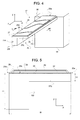
Figure 4 is a perspective view from above of a piezoelectric transducer according to one embodiment of the present invention, integrated in the converter ofFigure 2 ; -
Figure 5 is an enlarged cross-sectional view, taken in the line IV-IV ofFigure 2 , of the piezoelectric transducer ofFigure 4 ; -
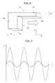
Figure 6 is a front view of the piezoelectric transducer ofFigure 5 in a deformed configuration; -
Figure 7 is a graph that shows oscillations of the piezoelectric transducer ofFigure 5 in response to various mechanical stresses; -
Figure 8 is an enlarged top plan view of a detail of the converter ofFigure 2 in a first configuration; -
Figure 9 is a top plan view of the detail ofFigure 8 in a second operative configuration; -
Figure 10 is a cross-sectional view of a piezoelectric transducer according to a different embodiment of the present invention; -
Figure 11 is a cross-sectional view of a piezoelectric transducer according to another embodiment of the present invention; and -
Figure 12 is a cross-sectional view of a piezoelectric transducer according to a further different embodiment of the present invention; and -
Figure 13 is a perspective view from above of a piezoelectric transducer according to a further embodiment of the present invention. - With reference to
Figure 1 , an energy-harvesting system is designated as a whole by thereference number 1. The energy-harvesting system 1 is particularly, but not exclusively, suited to being used for supplying electronic components and/or devices such as low-consumption sensors and actuators, which are of increasingly frequent use in portable electronic devices such as cellphones, tablets, portable computers (laptops), video cameras, photographic cameras, consoles for videogames, etc. - Electronic components and devices supplied by the energy-
harvesting system 1 may be rendered entirely or partially self-sufficient in order to reduce or eliminate absorption of energy from the main supply system (normally a battery), which thus has a greater autonomy, to the advantage of users. - In addition, in some applications, the energy-
harvesting system 1 may be used either as main supply source and as auxiliary supply source for the electronic components and/or devices indicated above. In this case, the energy-harvesting system 1 may be arranged alongside a conventional power-supply system, for example of the battery type, and enter into operation when the main power-supply system has run down or presents malfunctioning. - The energy-
harvesting system 1 comprises apiezoelectric converter 2, aharvesting interface 3, astorage element 5, a selective-connection device 6 and avoltage regulator 7. Further, an output of thevoltage regulator 7 supplies anelectrical load 8. - The
piezoelectric converter 2 supplies a harvesting voltage VH in response to energy supplied by anenvironmental energy source 4 external to theharvesting system 1. Thepiezoelectric converter 2 supplies a harvesting voltage VH in response to mechanical vibrations transmitted from the external environment and will be described in greater detail in what follows. - The
harvesting interface 3, when supplied by thestorage element 5, receives the harvesting voltage VH from thepiezoelectric converter 2 and supplies a charging current ICH to thestorage element 5. The energy stored in thestorage element 5 increases as a result of the charging current ICH and determines a storage voltage VST. - The selective-
connection device 6 selectively connects and disconnects a supply input 3a of theharvesting interface 3 and thestorage element 5 on the basis of the response of thepiezoelectric converter 2. More precisely, when the harvesting voltage VH exceeds an activation threshold VA, which represents a state in which thepiezoelectric converter 2 is active and receives environmental energy from outside, the selective-connection device 6 connects theharvesting interface 3 to thestorage element 5 so that theharvesting interface 3 receives the storage voltage VST present on thestorage element 5. The harvesting interface may thus use the harvesting voltage VH for charging thestorage element 5. Instead, when thepiezoelectric converter 2 does not receive environmental energy and the harvesting voltage VH is lower than the activation threshold VA, the selective-connection device 6 disconnects theharvesting interface 3 from thestorage element 5 so that the consumption of energy of theharvesting interface 3 ceases. - In one embodiment, in particular, the selective-connection device comprises a
switch 10 and adriving stage 11, configured to control theswitch 10 on the basis of the comparison between the harvesting voltage VH and the activation threshold VA. - The
voltage regulator 7 receives the storage voltage VST and supplies a regulated supply voltage VDD to theelectrical load 8 according to the requirement. - The
selective supply device 6 enables consumption of theharvesting interface 3 to be substantially reduced to zero in the absence of activity of thepiezoelectric converter 2 and thus prevents the energy accumulated on thestorage element 5 from being dissipated without an effective need when theharvesting system 1 is not in a condition to receive energy from the environment. - According to one embodiment of the invention, illustrated in
Figures 2 and 3 , thepiezoelectric converter 2 comprises a microstructure including a supportingbody 15, amovable mass 16, and a plurality of cantileverpiezoelectric transducers 17. The supportingbody 15, themovable mass 16, and part of the cantileverpiezoelectric transducers 17 are of semiconductor material, for example monocrystalline silicon. - The supporting
body 15 may be a semiconductor monolithic body, or else may be obtained by bonding two or more semiconductor chips, possibly with interposition of bonding layers and/or dielectric layers. - The
movable mass 16 is elastically connected to the supportingbody 15 by a system ofsuspensions 18, configured to enable displacements of themovable mass 16 according to an axis, generally an axis of translation or an axis of rotation. In the example described, in particular, themovable mass 16 may translate along an axis X between a first position X1 (Figure 2 ) and a second position X2 (Figure 3 ). Themovable mass 16 may comprise, in addition to semiconductor structures, also layers or portions of heavy metals, such as lead or tungsten, in order to improve the energy-harvesting efficiency. - A first
bistable mechanism 20 and a secondbistable mechanism 21 are connected to opposite sides of themovable mass 16 with respect to the axis X and are configured to enable movement of themovable mass 16 from the first position X1 to the second position X2, or vice versa from the second position X2 to the first position X1, selectively when a force directed along the axis X and higher than a trigger threshold is applied to themovable mass 16. In one embodiment, the firstbistable mechanism 20 and the secondbistable mechanism 21 are coupled to opposite sides of themass 16 with respect to the second axis X. - The first
bistable mechanism 20 and the secondbistable mechanism 21 have respective first stable configurations (Figure 2 ), when themovable mass 16 is in the first position X1, and respective second stable configurations (Figure 3 ), when themovable mass 16 is in the second position X2. The first stable configurations and the second stable configurations correspond to respective configurations of minimum of potential energy of the firstbistable mechanism 20 and of the secondbistable mechanism 21. When themovable mass 16 is subjected to forces of intensity lower than the trigger threshold, the firstbistable mechanism 20 and the secondbistable mechanism 21 may deform slightly and then return into the starting stable configuration after the force has been removed. When, instead, the force applied to themovable mass 16 exceeds the trigger threshold, the firstbistable mechanism 20 and the secondbistable mechanism 21 suddenly reach the stable configuration opposite to the starting stable configuration, even if the force is removed before the transition is completed. The energy stored by thebistable mechanisms movable mass 16. In this way, themovable mass 16 receives a stress of an impulsive type, which covers a very wide frequency band. The trigger threshold may be used as parameter to define with sufficient accuracy the conditions for switching from the first stable configuration to the second stable configuration and vice versa. - With reference to
Figures 4 and 5 , eachcantilever piezoelectric transducer 17 comprises abeam 25 of semiconductor material. Thebeam 25 extends in cantilever fashion from a respective anchorage portion 16a of themovable mass 16 in a main direction defined by an axis Y perpendicular to the axis X. Thebeam 25 is formed monolithically from themovable mass 16 and has aconstrained end 25a, fixed to the anchorage portion 16a of themovable mass 16, and afree end 25b, opposite to theconstrained end 25a. - The
beam 25 has aface 25c parallel to a plane XY defined by the axis X and by the axis Y. Theface 25c of thebeam 25 has a main dimension along the axis Y and a secondary dimension along the axis X. - A
piezoelectric layer 26 is arranged on at least one part of theface 25c of thebeam 25. In one embodiment, thepiezoelectric layer 26 may be of PZT (lead zirconate titanate). Thepiezoelectric layer 26 is arranged between afirst electrode 27 and asecond electrode 28. Thefirst electrode 27, in turn, lies on theface 25c of thebeam 25 and is electrically insulated therefrom by adielectric layer 29, made, for example, of silicon oxide. Theelectrodes face 25c and the stack that includes thefirst electrode 27, thepiezoelectric layer 26, and thesecond electrode 28 is coated by apassivation layer 30, made, for example, of silicon oxide. - The
beam 25 is shaped so as to bend in response to mechanical stresses transmitted to themovable mass 16, in particular so as to cause a local harvesting voltage between the faces of thepiezoelectric layer 26 in contact with thefirst electrode 27 and thesecond electrode 28. In practice, the deformations useful for setting up the local harvesting voltage include bending out of the plane XY defined by the axis X and by the axis Y. - The
beam 25 is shaped so as to bend out of the plane XY also in response to in-plane forces parallel to the axis X. In detail, a cross-section of thebeam 25 perpendicular to its main direction, i.e., perpendicular to the axis Y, is asymmetrical at least along a stretch of thebeam 25. In one embodiment, the cross-section of thebeam 25 is asymmetrical with respect to centroidal planes, in particular both to a centroidal plane parallel to the plane XY and to a centroidal plane parallel to a plane YZ, which is defined by the axis Y and by an axis Z perpendicular to the axis X and to the axis Y. In one embodiment, thebeam 25 has a first thickness T1 along a firstlongitudinal edge 25d and a second thickness T2, smaller than the first thickness T1, along a secondlongitudinal edge 25e. In one embodiment, in addition, the first thickness T1 is smaller than a width W of the beam 25 (parallel to the axis X). For example, the cross-section of thebeam 25 perpendicular to its main direction is L-shaped. A firstlongitudinal portion 25f of thebeam 25 extends along the firstlongitudinal edge 25d and has the first thickness T1, and a secondlongitudinal portion 25g of thebeam 25 extends along the secondlongitudinal edge 25e and has the second thickness T2. In one embodiment, the transition between the firstlongitudinal portion 25f and the secondlongitudinal portion 25g is defined by a wall 25h perpendicular to the axis X. - The
beam 25 undergoes deformation principally in response to forces that act in directions parallel to the axis Z (out-of-plane forces, in practice perpendicular to the plane XY). On account of the asymmetrical geometry, however, thebeam 25 responds with deformations out of the plane XY also to forces oriented in directions parallel to the axis X. As shown inFigure 6 , a force acting along the axis X on themovable mass 16 produces a first component of deformation (in the plane XY) and, consequently, a first displacement ΔX of thefree end 25b of thebeam 25 with respect to theconstrained end 25a. The first component of deformation does not contribute in itself to conversion of the mechanical energy into electrical energy because thepiezoelectric layer 26 is not loaded for generating a local harvesting voltage between thefirst electrode 27 and thesecond electrode 28. The force acting along the axis X produces, however, also a second component of perpendicular to the plane XY and a consequent second displacement ΔY of thefree end 25b of thebeam 25 with respect to theconstrained end 25a. This type of deformation is basically due to the asymmetry of thebeam 25, in particular of the cross-section perpendicular to the axis Y. The stresses produced on the cross-section, in fact, are in turn asymmetrical and lead to deformation out of the plane XY. Unlike the first component of deformation, the second component of deformation contributes to generate electrical energy because loading of thepiezoelectric layer 26 produces a local harvesting voltage between thefirst electrode 27 and thesecond electrode 28. The graph ofFigure 7 shows with a solid line the oscillations of thefree end 25b of thebeam 25 along the axis Z as a result of a force pulse parallel to the axis X. As may be noted, even though the oscillations have a smaller amplitude that the ones that derive from force pulses applied directly along the axis Z (dashed line), the contribution is, however, not negligible and significantly improves the overall efficiency of thepiezoelectric converter 2. -
Figures 9 and10 illustrate in greater detail the firstbistable mechanism 20. What is described in what follows basically applies also to the secondbistable mechanism 21, apart from the details that will be in any case described hereinafter. - The first
bistable mechanism 20 comprises a system of linear elastic elements. In one embodiment, in particular, the firstbistable mechanism 20 comprises a firstelastic lamina element 20a and a secondelastic lamina element 20b, which are defined by respective flexible plates of semiconductor material. Alternatively, theelastic lamina elements elastic lamina element 20a and the secondelastic lamina element 20b have respective ends fixed to a surface of the supportingbody 15 byanchorages 31 and for the rest are movable parallel to the plane XY between the first stable configuration and the second stable configuration. Furthermore, abridge element 32 joins central portions of the firstelastic lamina element 20a and of the secondelastic lamina element 20b to themovable mass 16. - In the first stable configuration and in the second stable configuration, the first
elastic lamina element 20a and the secondelastic lamina element 20b have an arched shape, with a geometry selected according to the desired force threshold, and are parallel to one another. More specifically, in the first stable configuration, the firstelastic lamina element 20a and the secondelastic lamina element 20b define respective first concavities, open on the side facing themovable mass 16. In the second stable configuration, instead, the firstelastic lamina element 20a and the secondelastic lamina element 20b define respective second concavities, open on the side opposite to themovable mass 16. - Also the second
bistable mechanism 21, not illustrated, comprises two elastic lamina elements fixed at the ends to the supportingbody 15 and at the centre to themovable mass 16 by a bridge element. The elastic lamina elements are arched with concavities open on the side opposite to themovable mass 16 in the first stable configuration and on the side facing themovable mass 16 in the second stable configuration. - As already mentioned previously, the transitions of the
bistable mechanisms bistable mechanisms movable mass 16 in an impulsive way. The cantileverpiezoelectric transducers 17, in addition to responding also to in-plane forces directed along the axis X, are excited over a wide frequency band, which also comprises the mechanical resonance frequency of the cantileverpiezoelectric transducers 17 themselves. In practice, the transitions of thebistable mechanisms cantilever piezoelectric transducers 17. In the absence of a frequency-translation mechanism, the response of the cantileverpiezoelectric transducers 17 would be attenuated or even negligible. Thanks to thebistable mechanisms -
Figures 10-12 show different embodiments of the invention, in which the cross-section of the beams has different profiles, once again asymmetrical. - In the example of
Figure 10 , the cross-section of abeam 125 is substantially triangular. Apiezoelectric layer 126 is located on aplane face 125c parallel to the plane XY. - In the example of
Figure 11 , a piezoelectric layer 226 is located on aface 225c of aplane beam 225 parallel to the plane XY. A face opposite to theface 225c is staircase shaped and has a profile that degrades from alongitudinal edge 225d, where the thickness of thebeam 225 is greater, to a secondlongitudinal edge 225e, where the thickness of thebeam 225 is smaller. - In the example of
Figure 12 , abeam 325 carries apiezoelectric layer 326 on oneface 325c. An opposite face of thebeam 325 has an arched profile degrading from alongitudinal edge 325d, where the thickness of thebeam 325 is greater, to a secondlongitudinal edge 325e, where the thickness of thebeam 325 is smaller. -
Figure 13 illustrates a detail of apiezoelectric converter 402, including acantilever piezoelectric transducer 417. Thecantilever piezoelectric transducer 417 comprises abeam 425 that extends in cantilever fashion from a supporting body, for example amovable mass 416 elastically constrained to a substrate (not illustrated). In a direction transverse to its own major dimension, thebeam 425 has an asymmetrical cross-section, for example L-shaped. A weight 426 is fixed to afree end 425b of thebeam 425. In one embodiment, the weight 426 is defined by a mass of semiconductor material of a single piece with thebeam 425 and having a thickness equal to the maximum thickness of thebeam 425 itself. The design of the weight 426, which may be easily controlled in the production stage, enables precise definition of the resonance frequency of thecantilever piezoelectric transducer 417. - Finally, it is evident that modifications and variations may be made to the piezoelectric transducer described herein, without thereby departing from the scope of the present invention, as defined in the annexed claims.
Claims (18)
- A piezoelectric transducer comprising:an anchorage (16a);a beam (25; 125; 225; 325; 425) of semiconductor material, cantilever extending from the anchorage (16a) in a main direction parallel to a first axis (Y) and having a face (25c; 125c; 225c; 325c) parallel to a first plane (XY) defined by the first axis (Y) and by a second axis (X) perpendicular to the first axis (Y); anda piezoelectric layer (26) on the face (25c; 125c; 225c; 325c) of the beam (25; 125; 225; 325; 425);a cross-section of the beam (25; 125; 225; 325; 425) perpendicular to the first axis (Y) being asymmetrical and shaped so that the beam (25; 125; 225; 325; 425) presents deformations out of the first plane (XY) in response to forces applied to the anchorage (16) and directed according to the second axis (X).
- A piezoelectric transducer according to claim 1, wherein the cross-section of the beam (25; 125; 225; 325; 425) perpendicular to the first axis (Y) is asymmetrical with respect to centroidal planes.
- A piezoelectric transducer according to claim 2, wherein the cross-section of the beam (25; 125; 225; 325; 425) perpendicular to the first axis (Y) is asymmetrical with respect to a centroidal plane parallel to the first plane (XY) and to a centroidal plane parallel to a second plane (YZ), which is defined by the first axis (Y) and by a third axis (Z) perpendicular to the first axis (Y) and to the second axis (X).
- A piezoelectric transducer according to any one of the preceding claims, wherein the beam (25) has a first thickness (T1) along a first longitudinal edge (25d) and a second thickness (T2), smaller than the first thickness (T1), along a second longitudinal edge (25e).
- A piezoelectric transducer according to claim 4, wherein a first longitudinal portion (25f) of the beam (25) extends along the first longitudinal edge (25d) and has the first thickness (T1); and a second longitudinal portion (25g) of the beam (25) extends along the second longitudinal edge (25e) and has the second thickness (T2).
- A piezoelectric transducer according to any one of the preceding claims, wherein the cross-section of the beam (25) perpendicular to the first axis (Y) is L-shaped.
- A piezoelectric transducer according to any one of the preceding claims, wherein the piezoelectric layer (26) is arranged between a first electrode (27), which lies on the face (25c) of the beam (25), and a second electrode (28).
- The piezoelectric transducer according to any one of the preceding claims, comprising a weight (426) at one end (425b) of the beam (425).
- A piezoelectric converter comprising:a supporting body (15) of semiconductor material;a mass (16) of semiconductor material, movable with respect to the supporting body (15); anda plurality of piezoelectric transducers (17) according to any one of the preceding claims anchored to the mass (16).
- A piezoelectric converter according to claim 9, wherein the mass (16) is elastically constrained to the supporting body (15) and is movable with respect to the supporting body (15) along the second axis (X) between a first position (X1) and a second position (X2).
- A piezoelectric converter according to claim 9 or claim 10, comprising a bistable device (20, 21) coupled to the mass (16) and configured to enable movement of the mass (16) between the first position (X1) and the second position (X2) in response selectively to forces that are oriented along the second axis (X) and have an intensity higher than a trigger threshold.
- A piezoelectric converter according to claim 11, wherein the bistable device (20, 21) has a first stable configuration when the mass (16) is in the first position (X1) and a second stable configuration when the mass (16) is in the second position (X2) and is connected to the mass so that forces applied to the mass (16) and oriented along the second axis (X) tend to deform the bistable device (20, 21).
- A piezoelectric converter according to claim 12, wherein the bistable device (20, 21) comprises a first bistable mechanism (20), which includes a first elastic lamina element (20a) and a second elastic lamina element (20b), which have respective ends fixed to the supporting body (15), and a bridge element (32), which connects central portions of the first elastic lamina element (20a) and of the second elastic lamina element (20b) to the mass (16).
- A piezoelectric converter according to claim 13, wherein the first elastic lamina element (20a) and the second elastic lamina element (20b) are arched and parallel to one another in the first stable configuration and in the second stable configuration and are movable parallel to the first plane (XY) between the first stable configuration and the second stable configuration.
- A piezoelectric converter according to claim 14, wherein the first elastic lamina element (20a) and the second elastic lamina element (20b) define, in the first stable configuration, respective first concavities open on the side facing the mass (16) and, in the second stable configuration, respective second concavities open on the side opposite to the mass (16).
- A converter according to any one of claims 13 to 15, wherein the bistable device (20, 21) comprises a second bistable mechanism (21), substantially the same as the first bistable mechanism (20), the first bistable mechanism (20) and the second bistable mechanism (21) being coupled to opposite sides of the mass (16) with respect to the second axis (X).
- A converter according to claim 16, wherein a first elastic lamina element and a second elastic lamina element of the second bistable mechanism (21) define, in the first stable configuration, respective first concavities open on the side opposite to the mass (16) and, in the second stable configuration, respective second concavities open on the side facing the mass (16).
- An energy-harvesting system comprising a piezoelectric converter (2) according to any one of claims 8 to 16 and configured to harvest environmental energy and to convert the environmental energy harvested into an electrical harvesting signal (VH);
a storage element (5), configured to store electrical energy deriving from conversion of the environmental energy harvested by the piezoelectric transducer (2); and
a harvesting interface (3), coupled to the transducer (2) and configured to supply an electrical charging signal (ICH) to the storage element (5) as a function of the electrical harvesting signal (VH).
Applications Claiming Priority (1)
| Application Number | Priority Date | Filing Date | Title |
|---|---|---|---|
| ITUB20151507 | 2015-06-18 |
Publications (2)
| Publication Number | Publication Date |
|---|---|
| EP3107202A1 true EP3107202A1 (en) | 2016-12-21 |
| EP3107202B1 EP3107202B1 (en) | 2018-06-13 |
Family
ID=53836789
Family Applications (1)
| Application Number | Title | Priority Date | Filing Date |
|---|---|---|---|
| EP15200411.5A Active EP3107202B1 (en) | 2015-06-18 | 2015-12-16 | Cantilever piezoelectric transducer |
Country Status (3)
| Country | Link |
|---|---|
| US (2) | US10135365B2 (en) |
| EP (1) | EP3107202B1 (en) |
| CN (2) | CN106257699B (en) |
Cited By (2)
| Publication number | Priority date | Publication date | Assignee | Title |
|---|---|---|---|---|
| EP3804117A1 (en) * | 2018-05-29 | 2021-04-14 | Université Savoie Mont Blanc | Vibrational energy recovery system |
| US20230308033A1 (en) * | 2020-07-06 | 2023-09-28 | Wenjing Wu | Self-generating device |
Families Citing this family (5)
| Publication number | Priority date | Publication date | Assignee | Title |
|---|---|---|---|---|
| ITTO20130652A1 (en) * | 2013-07-31 | 2015-02-01 | Milano Politecnico | PIEZOELECTRIC TRANSDUCER FOR AN ENERGY COLLECTION SYSTEM AND METHOD FOR ENERGY COLLECTION BY MEANS OF A PIEZOELECTRIC TRANSDUCER |
| CN106257699B (en) * | 2015-06-18 | 2019-02-22 | 意法半导体股份有限公司 | Cantilever PZT (piezoelectric transducer) |
| KR102452948B1 (en) * | 2017-07-18 | 2022-10-11 | 삼성전자주식회사 | micromechanical resonator and resonator system including the same |
| IT202000003967A1 (en) | 2020-02-26 | 2021-08-26 | St Microelectronics Srl | Microelectromechanical system and method for its manufacture |
| CN111063790B (en) * | 2020-03-12 | 2020-07-28 | 共达电声股份有限公司 | Piezoelectric transducer, method of manufacturing piezoelectric transducer, and electronic apparatus |
Citations (2)
| Publication number | Priority date | Publication date | Assignee | Title |
|---|---|---|---|---|
| US20070024715A1 (en) * | 2004-06-07 | 2007-02-01 | Taku Hirasawa | Actuator and micromotion mechanism having such actuator and camera module having such micromotion mechanism |
| US20110101827A1 (en) * | 2009-11-02 | 2011-05-05 | Toyota Motor Engineering & Manufacturing North America, Inc. | Energy harvesting device |
Family Cites Families (11)
| Publication number | Priority date | Publication date | Assignee | Title |
|---|---|---|---|---|
| WO2007037926A2 (en) * | 2005-09-23 | 2007-04-05 | Sharp Laboratories Of America, Inc. | Mems pixel sensor |
| US20080074002A1 (en) * | 2006-09-26 | 2008-03-27 | Shashank Priya | Piezoelectric energy harvester |
| WO2008150536A2 (en) * | 2007-05-31 | 2008-12-11 | Wayne State University | Piezo devices with air-spaced cantilever |
| US8143765B1 (en) * | 2008-01-30 | 2012-03-27 | TBT Group, Inc. | Self-powering headset, devices and related methods |
| MY162273A (en) * | 2008-09-29 | 2017-05-31 | Mimos Berhad | A device for maximum detection of vibrating energy for harvesting energy |
| WO2012105368A1 (en) * | 2011-02-04 | 2012-08-09 | 株式会社村田製作所 | Piezoelectric power-generation apparatus |
| KR101774301B1 (en) * | 2011-12-16 | 2017-09-20 | 한국전자통신연구원 | energy harvesting device and manufacturing of the same |
| US9294015B2 (en) * | 2012-05-25 | 2016-03-22 | Electronics And Telecommunications Research Institute | Piezoelectric energy harvesting array and method of manufacturing the same |
| CN105009442B (en) * | 2013-03-13 | 2017-06-23 | 住友理工株式会社 | Trt |
| ITTO20130652A1 (en) * | 2013-07-31 | 2015-02-01 | Milano Politecnico | PIEZOELECTRIC TRANSDUCER FOR AN ENERGY COLLECTION SYSTEM AND METHOD FOR ENERGY COLLECTION BY MEANS OF A PIEZOELECTRIC TRANSDUCER |
| CN106257699B (en) * | 2015-06-18 | 2019-02-22 | 意法半导体股份有限公司 | Cantilever PZT (piezoelectric transducer) |
-
2015
- 2015-11-30 CN CN201510860679.6A patent/CN106257699B/en active Active
- 2015-11-30 CN CN201520977697.8U patent/CN205595377U/en not_active Withdrawn - After Issue
- 2015-12-16 EP EP15200411.5A patent/EP3107202B1/en active Active
- 2015-12-28 US US14/980,762 patent/US10135365B2/en active Active
-
2018
- 2018-10-04 US US16/152,076 patent/US11183953B2/en active Active
Patent Citations (2)
| Publication number | Priority date | Publication date | Assignee | Title |
|---|---|---|---|---|
| US20070024715A1 (en) * | 2004-06-07 | 2007-02-01 | Taku Hirasawa | Actuator and micromotion mechanism having such actuator and camera module having such micromotion mechanism |
| US20110101827A1 (en) * | 2009-11-02 | 2011-05-05 | Toyota Motor Engineering & Manufacturing North America, Inc. | Energy harvesting device |
Non-Patent Citations (1)
| Title |
|---|
| YAMADA KEISUKE ED - JOSEPH PHIL ET AL: "Enhancing efficiency of piezoelectric element attached to beam using extended spacers", JOURNAL OF SOUND & VIBRATION, vol. 341, 14 April 2015 (2015-04-14), pages 31 - 52, XP029165155, ISSN: 0022-460X, DOI: 10.1016/J.JSV.2014.12.022 * |
Cited By (3)
| Publication number | Priority date | Publication date | Assignee | Title |
|---|---|---|---|---|
| EP3804117A1 (en) * | 2018-05-29 | 2021-04-14 | Université Savoie Mont Blanc | Vibrational energy recovery system |
| EP3804117B1 (en) * | 2018-05-29 | 2026-03-25 | Université Savoie Mont Blanc | Vibration energy harvester |
| US20230308033A1 (en) * | 2020-07-06 | 2023-09-28 | Wenjing Wu | Self-generating device |
Also Published As
| Publication number | Publication date |
|---|---|
| US10135365B2 (en) | 2018-11-20 |
| US20160373031A1 (en) | 2016-12-22 |
| US11183953B2 (en) | 2021-11-23 |
| CN106257699B (en) | 2019-02-22 |
| EP3107202B1 (en) | 2018-06-13 |
| US20190044458A1 (en) | 2019-02-07 |
| CN205595377U (en) | 2016-09-21 |
| CN106257699A (en) | 2016-12-28 |
Similar Documents
| Publication | Publication Date | Title |
|---|---|---|
| EP3107202B1 (en) | Cantilever piezoelectric transducer | |
| US10897215B2 (en) | Piezoelectric transducer for an energy-harvesting system | |
| EP2662971B1 (en) | Piezoelectric power generator | |
| US7948153B1 (en) | Piezoelectric energy harvester having planform-tapered interdigitated beams | |
| EP1654771B1 (en) | Strain energy shuttle apparatus and method for vibration energy harvesting | |
| US7520173B2 (en) | Interdigitated electrode for electronic device and electronic device using the same | |
| US9106160B2 (en) | Monolithic energy harvesting system, apparatus, and method | |
| US8093784B2 (en) | Piezoelectric power generating element, and method of generating electric power using the piezoelectric power generating element | |
| US20160211439A1 (en) | Multi-Axis Piezoelectric Transducer | |
| US11012006B2 (en) | Micro electromechanical system (MEMS) energy harvester with residual stress induced instability | |
| JP5386893B2 (en) | Piezoelectric generator | |
| US7986076B2 (en) | Energy harvesting device | |
| EP2566039A1 (en) | Vibration power generation device | |
| US9528502B2 (en) | System for conversing thermal energy into electrical energy | |
| JP2013500695A (en) | Bending device for deforming piezoelectric bending element, piezoelectric energy converter for converting mechanical energy into electric energy using the bending device, and method for converting mechanical energy into electric energy | |
| JP6641134B2 (en) | Mounting structure of power generation device and power generation method | |
| US10001372B2 (en) | Angular velocity detection device | |
| JP6699830B2 (en) | Piezoelectric sensor | |
| JP6844868B2 (en) | Power generation element | |
| JP5887457B2 (en) | Power generation element | |
| KR101332008B1 (en) | Energy harvester | |
| CN117559840A (en) | Actuator element and actuator module | |
| WO2018020639A1 (en) | Power generation device and power generation element | |
| JP2020065438A (en) | Power generation device mounting structure and power generation method | |
| CN107408622A (en) | Piezoelectric generator, button, radio module and method of manufacturing a piezoelectric generator |
Legal Events
| Date | Code | Title | Description |
|---|---|---|---|
| PUAI | Public reference made under article 153(3) epc to a published international application that has entered the european phase |
Free format text: ORIGINAL CODE: 0009012 |
|
| AK | Designated contracting states |
Kind code of ref document: A1 Designated state(s): AL AT BE BG CH CY CZ DE DK EE ES FI FR GB GR HR HU IE IS IT LI LT LU LV MC MK MT NL NO PL PT RO RS SE SI SK SM TR |
|
| AX | Request for extension of the european patent |
Extension state: BA ME |
|
| 17P | Request for examination filed |
Effective date: 20170620 |
|
| RBV | Designated contracting states (corrected) |
Designated state(s): AL AT BE BG CH CY CZ DE DK EE ES FI FR GB GR HR HU IE IS IT LI LT LU LV MC MK MT NL NO PL PT RO RS SE SI SK SM TR |
|
| GRAP | Despatch of communication of intention to grant a patent |
Free format text: ORIGINAL CODE: EPIDOSNIGR1 |
|
| INTG | Intention to grant announced |
Effective date: 20171220 |
|
| INTG | Intention to grant announced |
Effective date: 20180102 |
|
| GRAS | Grant fee paid |
Free format text: ORIGINAL CODE: EPIDOSNIGR3 |
|
| GRAA | (expected) grant |
Free format text: ORIGINAL CODE: 0009210 |
|
| AK | Designated contracting states |
Kind code of ref document: B1 Designated state(s): AL AT BE BG CH CY CZ DE DK EE ES FI FR GB GR HR HU IE IS IT LI LT LU LV MC MK MT NL NO PL PT RO RS SE SI SK SM TR |
|
| REG | Reference to a national code |
Ref country code: GB Ref legal event code: FG4D |
|
| REG | Reference to a national code |
Ref country code: CH Ref legal event code: EP Ref country code: AT Ref legal event code: REF Ref document number: 1009516 Country of ref document: AT Kind code of ref document: T Effective date: 20180615 |
|
| REG | Reference to a national code |
Ref country code: IE Ref legal event code: FG4D |
|
| REG | Reference to a national code |
Ref country code: DE Ref legal event code: R096 Ref document number: 602015012188 Country of ref document: DE |
|
| REG | Reference to a national code |
Ref country code: NL Ref legal event code: MP Effective date: 20180613 |
|
| REG | Reference to a national code |
Ref country code: LT Ref legal event code: MG4D |
|
| PG25 | Lapsed in a contracting state [announced via postgrant information from national office to epo] |
Ref country code: LT Free format text: LAPSE BECAUSE OF FAILURE TO SUBMIT A TRANSLATION OF THE DESCRIPTION OR TO PAY THE FEE WITHIN THE PRESCRIBED TIME-LIMIT Effective date: 20180613 Ref country code: NO Free format text: LAPSE BECAUSE OF FAILURE TO SUBMIT A TRANSLATION OF THE DESCRIPTION OR TO PAY THE FEE WITHIN THE PRESCRIBED TIME-LIMIT Effective date: 20180913 Ref country code: FI Free format text: LAPSE BECAUSE OF FAILURE TO SUBMIT A TRANSLATION OF THE DESCRIPTION OR TO PAY THE FEE WITHIN THE PRESCRIBED TIME-LIMIT Effective date: 20180613 Ref country code: SE Free format text: LAPSE BECAUSE OF FAILURE TO SUBMIT A TRANSLATION OF THE DESCRIPTION OR TO PAY THE FEE WITHIN THE PRESCRIBED TIME-LIMIT Effective date: 20180613 Ref country code: BG Free format text: LAPSE BECAUSE OF FAILURE TO SUBMIT A TRANSLATION OF THE DESCRIPTION OR TO PAY THE FEE WITHIN THE PRESCRIBED TIME-LIMIT Effective date: 20180913 Ref country code: ES Free format text: LAPSE BECAUSE OF FAILURE TO SUBMIT A TRANSLATION OF THE DESCRIPTION OR TO PAY THE FEE WITHIN THE PRESCRIBED TIME-LIMIT Effective date: 20180613 Ref country code: CY Free format text: LAPSE BECAUSE OF FAILURE TO SUBMIT A TRANSLATION OF THE DESCRIPTION OR TO PAY THE FEE WITHIN THE PRESCRIBED TIME-LIMIT Effective date: 20180613 |
|
| PG25 | Lapsed in a contracting state [announced via postgrant information from national office to epo] |
Ref country code: RS Free format text: LAPSE BECAUSE OF FAILURE TO SUBMIT A TRANSLATION OF THE DESCRIPTION OR TO PAY THE FEE WITHIN THE PRESCRIBED TIME-LIMIT Effective date: 20180613 Ref country code: HR Free format text: LAPSE BECAUSE OF FAILURE TO SUBMIT A TRANSLATION OF THE DESCRIPTION OR TO PAY THE FEE WITHIN THE PRESCRIBED TIME-LIMIT Effective date: 20180613 Ref country code: GR Free format text: LAPSE BECAUSE OF FAILURE TO SUBMIT A TRANSLATION OF THE DESCRIPTION OR TO PAY THE FEE WITHIN THE PRESCRIBED TIME-LIMIT Effective date: 20180914 Ref country code: LV Free format text: LAPSE BECAUSE OF FAILURE TO SUBMIT A TRANSLATION OF THE DESCRIPTION OR TO PAY THE FEE WITHIN THE PRESCRIBED TIME-LIMIT Effective date: 20180613 |
|
| REG | Reference to a national code |
Ref country code: AT Ref legal event code: MK05 Ref document number: 1009516 Country of ref document: AT Kind code of ref document: T Effective date: 20180613 |
|
| PG25 | Lapsed in a contracting state [announced via postgrant information from national office to epo] |
Ref country code: NL Free format text: LAPSE BECAUSE OF FAILURE TO SUBMIT A TRANSLATION OF THE DESCRIPTION OR TO PAY THE FEE WITHIN THE PRESCRIBED TIME-LIMIT Effective date: 20180613 |
|
| PG25 | Lapsed in a contracting state [announced via postgrant information from national office to epo] |
Ref country code: EE Free format text: LAPSE BECAUSE OF FAILURE TO SUBMIT A TRANSLATION OF THE DESCRIPTION OR TO PAY THE FEE WITHIN THE PRESCRIBED TIME-LIMIT Effective date: 20180613 Ref country code: AT Free format text: LAPSE BECAUSE OF FAILURE TO SUBMIT A TRANSLATION OF THE DESCRIPTION OR TO PAY THE FEE WITHIN THE PRESCRIBED TIME-LIMIT Effective date: 20180613 Ref country code: IS Free format text: LAPSE BECAUSE OF FAILURE TO SUBMIT A TRANSLATION OF THE DESCRIPTION OR TO PAY THE FEE WITHIN THE PRESCRIBED TIME-LIMIT Effective date: 20181013 Ref country code: RO Free format text: LAPSE BECAUSE OF FAILURE TO SUBMIT A TRANSLATION OF THE DESCRIPTION OR TO PAY THE FEE WITHIN THE PRESCRIBED TIME-LIMIT Effective date: 20180613 Ref country code: SK Free format text: LAPSE BECAUSE OF FAILURE TO SUBMIT A TRANSLATION OF THE DESCRIPTION OR TO PAY THE FEE WITHIN THE PRESCRIBED TIME-LIMIT Effective date: 20180613 Ref country code: CZ Free format text: LAPSE BECAUSE OF FAILURE TO SUBMIT A TRANSLATION OF THE DESCRIPTION OR TO PAY THE FEE WITHIN THE PRESCRIBED TIME-LIMIT Effective date: 20180613 Ref country code: PL Free format text: LAPSE BECAUSE OF FAILURE TO SUBMIT A TRANSLATION OF THE DESCRIPTION OR TO PAY THE FEE WITHIN THE PRESCRIBED TIME-LIMIT Effective date: 20180613 |
|
| PG25 | Lapsed in a contracting state [announced via postgrant information from national office to epo] |
Ref country code: IT Free format text: LAPSE BECAUSE OF FAILURE TO SUBMIT A TRANSLATION OF THE DESCRIPTION OR TO PAY THE FEE WITHIN THE PRESCRIBED TIME-LIMIT Effective date: 20180613 Ref country code: SM Free format text: LAPSE BECAUSE OF FAILURE TO SUBMIT A TRANSLATION OF THE DESCRIPTION OR TO PAY THE FEE WITHIN THE PRESCRIBED TIME-LIMIT Effective date: 20180613 |
|
| REG | Reference to a national code |
Ref country code: DE Ref legal event code: R097 Ref document number: 602015012188 Country of ref document: DE |
|
| PLBE | No opposition filed within time limit |
Free format text: ORIGINAL CODE: 0009261 |
|
| STAA | Information on the status of an ep patent application or granted ep patent |
Free format text: STATUS: NO OPPOSITION FILED WITHIN TIME LIMIT |
|
| 26N | No opposition filed |
Effective date: 20190314 |
|
| PG25 | Lapsed in a contracting state [announced via postgrant information from national office to epo] |
Ref country code: SI Free format text: LAPSE BECAUSE OF FAILURE TO SUBMIT A TRANSLATION OF THE DESCRIPTION OR TO PAY THE FEE WITHIN THE PRESCRIBED TIME-LIMIT Effective date: 20180613 Ref country code: DK Free format text: LAPSE BECAUSE OF FAILURE TO SUBMIT A TRANSLATION OF THE DESCRIPTION OR TO PAY THE FEE WITHIN THE PRESCRIBED TIME-LIMIT Effective date: 20180613 |
|
| REG | Reference to a national code |
Ref country code: CH Ref legal event code: PL |
|
| PG25 | Lapsed in a contracting state [announced via postgrant information from national office to epo] |
Ref country code: MC Free format text: LAPSE BECAUSE OF FAILURE TO SUBMIT A TRANSLATION OF THE DESCRIPTION OR TO PAY THE FEE WITHIN THE PRESCRIBED TIME-LIMIT Effective date: 20180613 Ref country code: LU Free format text: LAPSE BECAUSE OF NON-PAYMENT OF DUE FEES Effective date: 20181216 |
|
| REG | Reference to a national code |
Ref country code: IE Ref legal event code: MM4A |
|
| REG | Reference to a national code |
Ref country code: BE Ref legal event code: MM Effective date: 20181231 |
|
| PG25 | Lapsed in a contracting state [announced via postgrant information from national office to epo] |
Ref country code: FR Free format text: LAPSE BECAUSE OF NON-PAYMENT OF DUE FEES Effective date: 20181231 Ref country code: IE Free format text: LAPSE BECAUSE OF NON-PAYMENT OF DUE FEES Effective date: 20181216 |
|
| PG25 | Lapsed in a contracting state [announced via postgrant information from national office to epo] |
Ref country code: AL Free format text: LAPSE BECAUSE OF FAILURE TO SUBMIT A TRANSLATION OF THE DESCRIPTION OR TO PAY THE FEE WITHIN THE PRESCRIBED TIME-LIMIT Effective date: 20180613 Ref country code: BE Free format text: LAPSE BECAUSE OF NON-PAYMENT OF DUE FEES Effective date: 20181231 |
|
| PG25 | Lapsed in a contracting state [announced via postgrant information from national office to epo] |
Ref country code: LI Free format text: LAPSE BECAUSE OF NON-PAYMENT OF DUE FEES Effective date: 20181231 Ref country code: CH Free format text: LAPSE BECAUSE OF NON-PAYMENT OF DUE FEES Effective date: 20181231 |
|
| PG25 | Lapsed in a contracting state [announced via postgrant information from national office to epo] |
Ref country code: MT Free format text: LAPSE BECAUSE OF NON-PAYMENT OF DUE FEES Effective date: 20181216 |
|
| PG25 | Lapsed in a contracting state [announced via postgrant information from national office to epo] |
Ref country code: TR Free format text: LAPSE BECAUSE OF FAILURE TO SUBMIT A TRANSLATION OF THE DESCRIPTION OR TO PAY THE FEE WITHIN THE PRESCRIBED TIME-LIMIT Effective date: 20180613 |
|
| PG25 | Lapsed in a contracting state [announced via postgrant information from national office to epo] |
Ref country code: PT Free format text: LAPSE BECAUSE OF FAILURE TO SUBMIT A TRANSLATION OF THE DESCRIPTION OR TO PAY THE FEE WITHIN THE PRESCRIBED TIME-LIMIT Effective date: 20180613 |
|
| PG25 | Lapsed in a contracting state [announced via postgrant information from national office to epo] |
Ref country code: HU Free format text: LAPSE BECAUSE OF FAILURE TO SUBMIT A TRANSLATION OF THE DESCRIPTION OR TO PAY THE FEE WITHIN THE PRESCRIBED TIME-LIMIT; INVALID AB INITIO Effective date: 20151216 Ref country code: MK Free format text: LAPSE BECAUSE OF NON-PAYMENT OF DUE FEES Effective date: 20180613 |
|
| GBPC | Gb: european patent ceased through non-payment of renewal fee |
Effective date: 20191216 |
|
| PG25 | Lapsed in a contracting state [announced via postgrant information from national office to epo] |
Ref country code: GB Free format text: LAPSE BECAUSE OF NON-PAYMENT OF DUE FEES Effective date: 20191216 |
|
| PGFP | Annual fee paid to national office [announced via postgrant information from national office to epo] |
Ref country code: DE Payment date: 20251126 Year of fee payment: 11 |