EP3107173A1 - Demand control device and program - Google Patents
Demand control device and program Download PDFInfo
- Publication number
- EP3107173A1 EP3107173A1 EP14882313.1A EP14882313A EP3107173A1 EP 3107173 A1 EP3107173 A1 EP 3107173A1 EP 14882313 A EP14882313 A EP 14882313A EP 3107173 A1 EP3107173 A1 EP 3107173A1
- Authority
- EP
- European Patent Office
- Prior art keywords
- power
- group
- amount
- demand
- target
- Prior art date
- Legal status (The legal status is an assumption and is not a legal conclusion. Google has not performed a legal analysis and makes no representation as to the accuracy of the status listed.)
- Granted
Links
- 238000004378 air conditioning Methods 0.000 claims abstract description 101
- 238000005259 measurement Methods 0.000 claims abstract description 50
- 238000004364 calculation method Methods 0.000 claims description 18
- 238000009434 installation Methods 0.000 claims description 3
- 230000006866 deterioration Effects 0.000 abstract description 5
- 238000000034 method Methods 0.000 description 56
- 230000008569 process Effects 0.000 description 48
- 230000007613 environmental effect Effects 0.000 description 14
- 238000013480 data collection Methods 0.000 description 12
- 238000010586 diagram Methods 0.000 description 11
- 230000009471 action Effects 0.000 description 8
- 230000005855 radiation Effects 0.000 description 7
- 230000009467 reduction Effects 0.000 description 6
- 230000000875 corresponding effect Effects 0.000 description 5
- 230000007704 transition Effects 0.000 description 4
- 230000005540 biological transmission Effects 0.000 description 3
- 238000007664 blowing Methods 0.000 description 3
- 238000004891 communication Methods 0.000 description 3
- 239000000470 constituent Substances 0.000 description 3
- 230000006870 function Effects 0.000 description 2
- 230000008859 change Effects 0.000 description 1
- 238000012790 confirmation Methods 0.000 description 1
- 238000001816 cooling Methods 0.000 description 1
- 230000002079 cooperative effect Effects 0.000 description 1
- 230000003247 decreasing effect Effects 0.000 description 1
- 230000000694 effects Effects 0.000 description 1
- 230000005611 electricity Effects 0.000 description 1
- 238000005516 engineering process Methods 0.000 description 1
- 238000010438 heat treatment Methods 0.000 description 1
- 230000004048 modification Effects 0.000 description 1
- 238000012986 modification Methods 0.000 description 1
Images


Classifications
-
- H—ELECTRICITY
- H02—GENERATION; CONVERSION OR DISTRIBUTION OF ELECTRIC POWER
- H02J—CIRCUIT ARRANGEMENTS OR SYSTEMS FOR SUPPLYING OR DISTRIBUTING ELECTRIC POWER; SYSTEMS FOR STORING ELECTRIC ENERGY
- H02J3/00—Circuit arrangements for ac mains or ac distribution networks
- H02J3/003—Load forecast, e.g. methods or systems for forecasting future load demand
-
- F—MECHANICAL ENGINEERING; LIGHTING; HEATING; WEAPONS; BLASTING
- F24—HEATING; RANGES; VENTILATING
- F24F—AIR-CONDITIONING; AIR-HUMIDIFICATION; VENTILATION; USE OF AIR CURRENTS FOR SCREENING
- F24F11/00—Control or safety arrangements
- F24F11/30—Control or safety arrangements for purposes related to the operation of the system, e.g. for safety or monitoring
- F24F11/46—Improving electric energy efficiency or saving
- F24F11/47—Responding to energy costs
-
- F—MECHANICAL ENGINEERING; LIGHTING; HEATING; WEAPONS; BLASTING
- F24—HEATING; RANGES; VENTILATING
- F24F—AIR-CONDITIONING; AIR-HUMIDIFICATION; VENTILATION; USE OF AIR CURRENTS FOR SCREENING
- F24F11/00—Control or safety arrangements
- F24F11/50—Control or safety arrangements characterised by user interfaces or communication
- F24F11/61—Control or safety arrangements characterised by user interfaces or communication using timers
-
- F—MECHANICAL ENGINEERING; LIGHTING; HEATING; WEAPONS; BLASTING
- F24—HEATING; RANGES; VENTILATING
- F24F—AIR-CONDITIONING; AIR-HUMIDIFICATION; VENTILATION; USE OF AIR CURRENTS FOR SCREENING
- F24F11/00—Control or safety arrangements
- F24F11/62—Control or safety arrangements characterised by the type of control or by internal processing, e.g. using fuzzy logic, adaptive control or estimation of values
- F24F11/63—Electronic processing
- F24F11/65—Electronic processing for selecting an operating mode
-
- G—PHYSICS
- G05—CONTROLLING; REGULATING
- G05B—CONTROL OR REGULATING SYSTEMS IN GENERAL; FUNCTIONAL ELEMENTS OF SUCH SYSTEMS; MONITORING OR TESTING ARRANGEMENTS FOR SUCH SYSTEMS OR ELEMENTS
- G05B11/00—Automatic controllers
- G05B11/01—Automatic controllers electric
-
- G—PHYSICS
- G05—CONTROLLING; REGULATING
- G05B—CONTROL OR REGULATING SYSTEMS IN GENERAL; FUNCTIONAL ELEMENTS OF SUCH SYSTEMS; MONITORING OR TESTING ARRANGEMENTS FOR SUCH SYSTEMS OR ELEMENTS
- G05B13/00—Adaptive control systems, i.e. systems automatically adjusting themselves to have a performance which is optimum according to some preassigned criterion
- G05B13/02—Adaptive control systems, i.e. systems automatically adjusting themselves to have a performance which is optimum according to some preassigned criterion electric
- G05B13/0205—Adaptive control systems, i.e. systems automatically adjusting themselves to have a performance which is optimum according to some preassigned criterion electric not using a model or a simulator of the controlled system
- G05B13/021—Adaptive control systems, i.e. systems automatically adjusting themselves to have a performance which is optimum according to some preassigned criterion electric not using a model or a simulator of the controlled system in which a variable is automatically adjusted to optimise the performance
-
- G—PHYSICS
- G05—CONTROLLING; REGULATING
- G05B—CONTROL OR REGULATING SYSTEMS IN GENERAL; FUNCTIONAL ELEMENTS OF SUCH SYSTEMS; MONITORING OR TESTING ARRANGEMENTS FOR SUCH SYSTEMS OR ELEMENTS
- G05B19/00—Programme-control systems
- G05B19/02—Programme-control systems electric
- G05B19/04—Programme control other than numerical control, i.e. in sequence controllers or logic controllers
- G05B19/042—Programme control other than numerical control, i.e. in sequence controllers or logic controllers using digital processors
-
- H—ELECTRICITY
- H02—GENERATION; CONVERSION OR DISTRIBUTION OF ELECTRIC POWER
- H02J—CIRCUIT ARRANGEMENTS OR SYSTEMS FOR SUPPLYING OR DISTRIBUTING ELECTRIC POWER; SYSTEMS FOR STORING ELECTRIC ENERGY
- H02J3/00—Circuit arrangements for ac mains or ac distribution networks
- H02J3/12—Circuit arrangements for ac mains or ac distribution networks for adjusting voltage in ac networks by changing a characteristic of the network load
- H02J3/14—Circuit arrangements for ac mains or ac distribution networks for adjusting voltage in ac networks by changing a characteristic of the network load by switching loads on to, or off from, network, e.g. progressively balanced loading
-
- H—ELECTRICITY
- H02—GENERATION; CONVERSION OR DISTRIBUTION OF ELECTRIC POWER
- H02J—CIRCUIT ARRANGEMENTS OR SYSTEMS FOR SUPPLYING OR DISTRIBUTING ELECTRIC POWER; SYSTEMS FOR STORING ELECTRIC ENERGY
- H02J4/00—Circuit arrangements for mains or distribution networks not specified as ac or dc
-
- F—MECHANICAL ENGINEERING; LIGHTING; HEATING; WEAPONS; BLASTING
- F24—HEATING; RANGES; VENTILATING
- F24F—AIR-CONDITIONING; AIR-HUMIDIFICATION; VENTILATION; USE OF AIR CURRENTS FOR SCREENING
- F24F11/00—Control or safety arrangements
- F24F11/30—Control or safety arrangements for purposes related to the operation of the system, e.g. for safety or monitoring
- F24F11/46—Improving electric energy efficiency or saving
-
- F—MECHANICAL ENGINEERING; LIGHTING; HEATING; WEAPONS; BLASTING
- F24—HEATING; RANGES; VENTILATING
- F24F—AIR-CONDITIONING; AIR-HUMIDIFICATION; VENTILATION; USE OF AIR CURRENTS FOR SCREENING
- F24F11/00—Control or safety arrangements
- F24F11/62—Control or safety arrangements characterised by the type of control or by internal processing, e.g. using fuzzy logic, adaptive control or estimation of values
- F24F11/63—Electronic processing
-
- F—MECHANICAL ENGINEERING; LIGHTING; HEATING; WEAPONS; BLASTING
- F24—HEATING; RANGES; VENTILATING
- F24F—AIR-CONDITIONING; AIR-HUMIDIFICATION; VENTILATION; USE OF AIR CURRENTS FOR SCREENING
- F24F2110/00—Control inputs relating to air properties
-
- F—MECHANICAL ENGINEERING; LIGHTING; HEATING; WEAPONS; BLASTING
- F24—HEATING; RANGES; VENTILATING
- F24F—AIR-CONDITIONING; AIR-HUMIDIFICATION; VENTILATION; USE OF AIR CURRENTS FOR SCREENING
- F24F2130/00—Control inputs relating to environmental factors not covered by group F24F2110/00
-
- F—MECHANICAL ENGINEERING; LIGHTING; HEATING; WEAPONS; BLASTING
- F24—HEATING; RANGES; VENTILATING
- F24F—AIR-CONDITIONING; AIR-HUMIDIFICATION; VENTILATION; USE OF AIR CURRENTS FOR SCREENING
- F24F2130/00—Control inputs relating to environmental factors not covered by group F24F2110/00
- F24F2130/10—Weather information or forecasts
-
- F—MECHANICAL ENGINEERING; LIGHTING; HEATING; WEAPONS; BLASTING
- F24—HEATING; RANGES; VENTILATING
- F24F—AIR-CONDITIONING; AIR-HUMIDIFICATION; VENTILATION; USE OF AIR CURRENTS FOR SCREENING
- F24F2140/00—Control inputs relating to system states
- F24F2140/50—Load
-
- F—MECHANICAL ENGINEERING; LIGHTING; HEATING; WEAPONS; BLASTING
- F24—HEATING; RANGES; VENTILATING
- F24F—AIR-CONDITIONING; AIR-HUMIDIFICATION; VENTILATION; USE OF AIR CURRENTS FOR SCREENING
- F24F2140/00—Control inputs relating to system states
- F24F2140/60—Energy consumption
-
- G—PHYSICS
- G05—CONTROLLING; REGULATING
- G05B—CONTROL OR REGULATING SYSTEMS IN GENERAL; FUNCTIONAL ELEMENTS OF SUCH SYSTEMS; MONITORING OR TESTING ARRANGEMENTS FOR SUCH SYSTEMS OR ELEMENTS
- G05B2219/00—Program-control systems
- G05B2219/30—Nc systems
- G05B2219/35—Nc in input of data, input till input file format
- G05B2219/35212—Estimating a cost associated with each operation, amount of time, target cost
-
- G—PHYSICS
- G05—CONTROLLING; REGULATING
- G05B—CONTROL OR REGULATING SYSTEMS IN GENERAL; FUNCTIONAL ELEMENTS OF SUCH SYSTEMS; MONITORING OR TESTING ARRANGEMENTS FOR SUCH SYSTEMS OR ELEMENTS
- G05B2219/00—Program-control systems
- G05B2219/30—Nc systems
- G05B2219/35—Nc in input of data, input till input file format
- G05B2219/35215—Generate optimal nc program variant as function of cost, time, surface, energy
-
- H—ELECTRICITY
- H02—GENERATION; CONVERSION OR DISTRIBUTION OF ELECTRIC POWER
- H02J—CIRCUIT ARRANGEMENTS OR SYSTEMS FOR SUPPLYING OR DISTRIBUTING ELECTRIC POWER; SYSTEMS FOR STORING ELECTRIC ENERGY
- H02J2310/00—The network for supplying or distributing electric power characterised by its spatial reach or by the load
- H02J2310/10—The network having a local or delimited stationary reach
- H02J2310/12—The local stationary network supplying a household or a building
- H02J2310/14—The load or loads being home appliances
-
- Y—GENERAL TAGGING OF NEW TECHNOLOGICAL DEVELOPMENTS; GENERAL TAGGING OF CROSS-SECTIONAL TECHNOLOGIES SPANNING OVER SEVERAL SECTIONS OF THE IPC; TECHNICAL SUBJECTS COVERED BY FORMER USPC CROSS-REFERENCE ART COLLECTIONS [XRACs] AND DIGESTS
- Y02—TECHNOLOGIES OR APPLICATIONS FOR MITIGATION OR ADAPTATION AGAINST CLIMATE CHANGE
- Y02B—CLIMATE CHANGE MITIGATION TECHNOLOGIES RELATED TO BUILDINGS, e.g. HOUSING, HOUSE APPLIANCES OR RELATED END-USER APPLICATIONS
- Y02B70/00—Technologies for an efficient end-user side electric power management and consumption
- Y02B70/30—Systems integrating technologies related to power network operation and communication or information technologies for improving the carbon footprint of the management of residential or tertiary loads, i.e. smart grids as climate change mitigation technology in the buildings sector, including also the last stages of power distribution and the control, monitoring or operating management systems at local level
- Y02B70/3225—Demand response systems, e.g. load shedding, peak shaving
-
- Y—GENERAL TAGGING OF NEW TECHNOLOGICAL DEVELOPMENTS; GENERAL TAGGING OF CROSS-SECTIONAL TECHNOLOGIES SPANNING OVER SEVERAL SECTIONS OF THE IPC; TECHNICAL SUBJECTS COVERED BY FORMER USPC CROSS-REFERENCE ART COLLECTIONS [XRACs] AND DIGESTS
- Y02—TECHNOLOGIES OR APPLICATIONS FOR MITIGATION OR ADAPTATION AGAINST CLIMATE CHANGE
- Y02P—CLIMATE CHANGE MITIGATION TECHNOLOGIES IN THE PRODUCTION OR PROCESSING OF GOODS
- Y02P80/00—Climate change mitigation technologies for sector-wide applications
- Y02P80/10—Efficient use of energy, e.g. using compressed air or pressurized fluid as energy carrier
- Y02P80/14—District level solutions, i.e. local energy networks
-
- Y—GENERAL TAGGING OF NEW TECHNOLOGICAL DEVELOPMENTS; GENERAL TAGGING OF CROSS-SECTIONAL TECHNOLOGIES SPANNING OVER SEVERAL SECTIONS OF THE IPC; TECHNICAL SUBJECTS COVERED BY FORMER USPC CROSS-REFERENCE ART COLLECTIONS [XRACs] AND DIGESTS
- Y04—INFORMATION OR COMMUNICATION TECHNOLOGIES HAVING AN IMPACT ON OTHER TECHNOLOGY AREAS
- Y04S—SYSTEMS INTEGRATING TECHNOLOGIES RELATED TO POWER NETWORK OPERATION, COMMUNICATION OR INFORMATION TECHNOLOGIES FOR IMPROVING THE ELECTRICAL POWER GENERATION, TRANSMISSION, DISTRIBUTION, MANAGEMENT OR USAGE, i.e. SMART GRIDS
- Y04S20/00—Management or operation of end-user stationary applications or the last stages of power distribution; Controlling, monitoring or operating thereof
- Y04S20/20—End-user application control systems
- Y04S20/222—Demand response systems, e.g. load shedding, peak shaving
-
- Y—GENERAL TAGGING OF NEW TECHNOLOGICAL DEVELOPMENTS; GENERAL TAGGING OF CROSS-SECTIONAL TECHNOLOGIES SPANNING OVER SEVERAL SECTIONS OF THE IPC; TECHNICAL SUBJECTS COVERED BY FORMER USPC CROSS-REFERENCE ART COLLECTIONS [XRACs] AND DIGESTS
- Y04—INFORMATION OR COMMUNICATION TECHNOLOGIES HAVING AN IMPACT ON OTHER TECHNOLOGY AREAS
- Y04S—SYSTEMS INTEGRATING TECHNOLOGIES RELATED TO POWER NETWORK OPERATION, COMMUNICATION OR INFORMATION TECHNOLOGIES FOR IMPROVING THE ELECTRICAL POWER GENERATION, TRANSMISSION, DISTRIBUTION, MANAGEMENT OR USAGE, i.e. SMART GRIDS
- Y04S20/00—Management or operation of end-user stationary applications or the last stages of power distribution; Controlling, monitoring or operating thereof
- Y04S20/20—End-user application control systems
- Y04S20/242—Home appliances
- Y04S20/244—Home appliances the home appliances being or involving heating ventilating and air conditioning [HVAC] units
Definitions
- the present invention relates to a demand control device and a program, and particularly relates to air-conditioning control using an intermittent shut-off operation.
- a company having a demand contract with a power company performs demand management so as not to exceed maximum demand power (a demand value).
- the demand contract is a contract in which an upper limit of a power consumption amount for each period, which is called a demand time limit, is defined as the maximum demand power.
- a power consumption amount an integrated value
- an electrical facility needs to be operated with low power, and as a technique for that, there is an technique called an intermittent shut-off operation or rotation operation (hereinafter, collectively referred to as an "intermittent shut-off operation") of an air-conditioning indoor unit.
- the intermittent shut-off operation is an air-conditioning control method in which power consumption amount is to be reduced by suspending in order a plurality of indoor units for a certain period of time instead of continuously operating them, that is, by performing a so-called thinning operation.
- Patent Literature 1 proposes a technique in which a power consumption amount for an initial period in a demand time limit is calculated while external factors, such as an outside air temperature and a solar radiation amount measured N hours before the demand time limit are taken into consideration, the power consumption amount for the remaining time in the same demand time limit is predicted from the calculated power consumption amount, then, when it is predicted that the power consumption in the demand time limit exceeds the maximum demand power, a power amount to be reduced is calculated, and a shut-off time of an electric device is calculated based on the calculated power amount which is a reduction target.
- Patent Literature 1 Although external factors, such as an outside air temperature and a solar radiation amount, are taken into consideration when a power consumption amount is predicted, a constant is used for a calculation expression for a power amount to be reduced. Furthermore, a solar radiation amount and the like measured N hours before a demand time limit are used. Moreover, an indoor temperature to be set can be changed according to the number of persons in a room. As described above, in Patent Literature 1, errors can easily occur when external conditions, such as weather, and indoor conditions are constantly changed, and an intermittent shut-off operation is not necessarily controlled while a comfortable indoor environment is maintained.
- An object of the present invention is to perform air-conditioning control in a low power operation so as not to exceed a target demand power amount in a predetermined measurement period while preventing deterioration of comfortableness of a living space.
- a demand control device includes: air-conditioning control means to perform low power operation control to make a group to which one or more indoor units belong perform a low power operation on a per-group basis; estimation means to estimate, as reducible power of the group, power calculated from a power amount reduced when each group separately performs the low power operation for a predetermined measurement unit time in a predetermined measurement period from a start point of a demand time limit; prediction means to predict a power consumption amount at an end point of the demand time limit; and calculation means to calculate, when the power consumption amount predicted by the prediction means exceeds a target demand power amount previously set to the demand time limit, a power amount to be reduced in order not to exceed the target demand power amount as a target reduced power amount, distribute the target reduced power amount to each group according to previously set distribution criteria, and calculate, for each group, a low power operation time to reduce the target reduced power amount distributed for each group based on the reducible power, and the air-conditioning control means makes the group perform the low power operation for the low power operation time calculated
- power consumption measurement means which is attached to an inverter type outdoor unit connected with the indoor unit which belongs to one or more groups, to measure a power consumption of the outdoor unit, is included, and the estimation means estimates, based on, when any one of groups performs the low power operation, the power consumption measured by the power consumption measurement means attached to the outdoor unit connected with the indoor unit which belongs to the group, a reducible power amount of the group.
- the estimation means estimates, from, when any one of groups performs the low power operation, operation frequency of a compressor of the outdoor unit connected with the indoor unit which belongs to the group, power consumption of the group, and estimates a reducible power amount of the group based on the estimated power consumption.
- the estimation means generates a correlation model based on actual result information on the operation frequency and the power consumption of the compressor, and estimates a power consumption amount of the group from the correlation model.
- calculation means evenly distributes the calculated target reduced power amount to each group according to the previously set distribution criteria.
- the calculation means distributes, when the indoor units are grouped into a plurality of groups based on an installation place and each group is allocated to any one of a plurality of areas, the target reduced power amount to each area, distributes, to each group allocated to the area, the target reduced power amount distributed to each area, and calculates, for each group, the low power operation time to reduce the distributed target reduced power amount for each group based on the reducible power.
- calculation means evenly distributes the target reduced power amount to each area.
- a program causes a computer mounted in a demand control device to function as: air-conditioning control means to perform low power operation control to make a group to which one or more indoor units belong perform a low power operation on a per-group basis; estimation means to estimate, as reducible power of the group, power calculated from a power amount reduced when each group separately performs the low power operation for a predetermined measurement unit time in a predetermined measurement period from a start point of a demand time limit; prediction means to predict a power consumption amount at an end point of the demand time limit; and calculation means to calculate, when the power consumption amount predicted by the prediction means exceeds a target demand power amount previously set to the demand time limit, a power amount to be reduced in order not to exceed the target demand power amount as a target reduced power amount, distribute the target reduced power amount to each group according to previously set distribution criteria, and calculate, for each group, a low power operation time to reduce the target reduced power amount distributed for each group based on the reducible power, and the air-conditioning control means makes the group perform
- the present invention it is possible to perform air-conditioning control in a low power operation so as not to exceed a target demand power amount while preventing deterioration of comfortableness of each air-conditioning space.
- Fig. 1 is a diagram illustrating an entire and block configuration of a building management system having an embodiment of a demand control device according to the present invention.
- Fig. 1 illustrates a configuration in which an environmental information measurement unit 3, a demand control device 30, an air-conditioning controller 4, a power consumption measurement unit 5, a lighting controller 8, and other electrical facilities 9 are connected with a network 1.
- the devices 3 to 5, 8, 9, and 30 exchange data and information, such as control and instructions, via the network 1.
- the environmental information measurement unit 3 is means to acquire, by measurement, information indicating environments surrounding a building which is a management target, and is implemented by various sensors and the like.
- the present embodiment is a technology suitable for an air-conditioning facility in electrical facilities which are demand management targets, and the environmental information measurement unit 3 acquires, for example, an outside air temperature, a solar radiation amount, and the like as environmental information related to air-conditioning, particularly as information related to variation factors of thermal load of the air-conditioning facility.
- the demand control device 30 is included in a building management server which manages the entire building management system, is a main control device used to perform the demand management based on measurement values and the like by a connected watthour meter 2, and is a device to perform characteristic air-conditioning control in the present embodiment. Obviously, the demand control device 30 may not be included in the building management server and may be configured as an independent device.
- the air-conditioning controller 4 is a controller which performs action control of a connected air-conditioning facility under the control of the demand control device 30.
- the air-conditioning controller 4 in the present embodiment is connected with two outdoor units 6.
- the power consumption measurement unit 5 is provided as power consumption measurement means, and is implemented by a wattmeter which measures the power consumption of the outdoor unit 6 to which it is attached. In the present embodiment, it is assumed that the power consumption measurement unit 5 is attached only to an outdoor unit A.
- the lighting controller 8 controls lighting 81 installed in the building.
- the other electrical facilities 9 are facilities, other than the air-conditioning facility and the lighting facility, which consume electricity.
- Each of a plurality of indoor units 7 installed in living spaces in the building is connected to an outdoor unit 6.
- a group of indoor units may be allocated to an area, such as a north side or a south side on the same floor, where change of a room temperature is different from another area according to a solar radiation amount or an outside air temperature.
- the indoor units 7 in the present embodiment are included in either of two areas A and B (hereinafter, referred to as a "zone") as illustrated in Fig. 1 , and categorized into two groups A1 and A2 in the zone A, and two groups B1 and B2 in the zone B.
- a group is a unit to perform an intermittent shut-off operation.
- the intermittent shut-off operation is the same as a shut-off operation in the present embodiment, and means that (groups of) the indoor units 7 operate with low load (low power) by performing a suspending operation or an air blowing operation, and the like.
- the low load (low power) operation is not necessarily limited to the operation in which the outdoor unit 6 is completely suspended, and includes an operation in which the outdoor unit 6 operates with lower power than normal power by turning a thermostat off or changing a temperature.
- each number of air-conditioning controllers 4, outdoor units 6 connected with the air-conditioning controller 4, indoor units 7 connected with the outdoor units 6, zones, groups included in the zones, groups, indoor units 7 included in the groups which are illustrated in Fig. 1 is an example and is not necessarily limited to the number.
- Fig. 2 is a hardware configuration diagram of a computer forming the demand control device 30 in the present embodiment.
- a computer forming the demand control device 30 can be implemented by an existing general hardware configuration. That is, as illustrated in Fig. 2 , the computer is configured by connecting, with an internal bus 21, a CPU 11, a ROM 12, a RAM 13, a hard disk drive (HDD) controller 15 connected with an HDD 14, an input/output controller 19 connected with a mouse 16 and a keyboard 17 which are provided as input means and a display 18 provided as a display device, and a network controller 20 provided as communication means.
- the computer is configured by connecting, with an internal bus 21, a CPU 11, a ROM 12, a RAM 13, a hard disk drive (HDD) controller 15 connected with an HDD 14, an input/output controller 19 connected with a mouse 16 and a keyboard 17 which are provided as input means and a display 18 provided as a display device, and a network controller 20 provided as communication means.
- HDD hard disk drive
- the air-conditioning controller 4 incorporates a computer and has a configuration similar to Fig. 2 .
- the demand control device 30 in the present embodiment includes an environmental information collection unit 31, a power data collection unit 32, a frequency data collection unit 33, a power consumption amount prediction unit 34, an information transmission unit 35, a demand control management unit 36, an air-conditioning facility information storage unit 37, a frequency characteristics information storage unit 38, an actual result information storage unit 39, and a demand shut-off list 40.
- constituent elements which implement conventionally mounted functions as the demand control device 30 but are not used for the description in the present embodiment, have been omitted from Fig. 1 .
- the environmental information collection unit 31 is provided as acquisition means, and collects, via the network 1, environmental information measured by the environmental information measurement unit 3.
- the power data collection unit 32 collects, via the network 1, power consumption measured by the power consumption measurement unit 5.
- the outdoor unit 6 is a heat pump air-conditioner, and performs cooling and heating by rotating a compressor. At this time, the outdoor unit 6 records the operation frequency of the compressor.
- the frequency data collection unit 33 collects the operation frequency data of the outdoor unit 6 via the air-conditioning controller 4 and the network 1.
- the power consumption amount prediction unit 34 is provided as prediction means, inputs a measurement value by the watthour meter 2, and predicts a power consumption amount at the end point of a demand time limit from the actual result of the power consumption amount from the start point of the demand time limit to the present point in the demand time limit.
- the method for calculating the predicted power consumption amount may be the same as conventional ones.
- the power consumption amount prediction unit 34 basically predicts the power consumption amount based on the correlation between the operation frequency and the power of the outdoor unit. As data indicating the correlation between the operation frequency and the power, for example, a catalogue value may be used.
- the information transmission unit 35 notifies the building management server of the situation related to the demand control in the demand control device 30.
- the demand control management unit 36 includes a reducible-power-amount estimation unit 361 and a reduced-power-amount determination unit 362, and performs the demand management by entire control of the air-conditioning control and the like while performing the action controls of the other constituent elements 31 to 35.
- the demand control management unit 36 in the present embodiment is provided as air-conditioning control means, and performs the intermittent shut-off operation control in which a group unit to which one or more indoor units 7 belong performs the shut-off operation.
- the reducible-power-amount estimation unit 361 is provided as estimation means, and estimates, as the reducible power of the group, the power calculated from the reduced power amount when each group separately performs the shut-off operation for a predetermined shut-off unit time in a predetermined measurement period from the start point of the demand time limit.
- the reduced-power-amount determination unit 362 is provided as calculation means, calculates, when the power consumption amount predicted by the power consumption amount prediction unit 34 exceeds a target demand power amount previously set to the demand time limit, the power amount to be reduced in order not to exceed the target demand power amount as a target reduced power amount, distributes the target reduced power amount to each group according to previously set distribution criteria, and calculates, for each group, a shut-off time to reduce the distributed target reduced power amount for each group based on the reducible power amount.
- the previously set distribution criteria the case where the target reduced power amount is evenly distributed to each group will be exemplified.
- frequency characteristics information which is used when the power consumption amount of the group is estimated, when any one of the groups performs the shut-off operation, from the operation frequency of the outdoor unit 6 connected with the indoor unit 7 which belongs to the group, is stored.
- the frequency characteristics information may be previously set according to a catalogue value or the like, or may be learnt from an actual result value and set.
- a model Fig. 7
- the frequency characteristics information will be described together with the description for actions.
- actual result information related to power consumption is accumulated. Specifically, a date and time when power is consumed, the power consumption (kW) of each outdoor unit 6 at the date and time, and environmental information, such as the outside air temperature, the solar radiation amount, and the like, is accumulated.
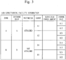
- Fig. 3 is a diagram illustrating an example of a data configuration of air-conditioning facility information stored in the air-conditioning facility information storage unit 37 in the present embodiment.
- the air-conditioning facility information includes the items of, in addition to the correspondence relation of the zone, the outdoor unit 6, the group, and the indoor unit 7 in the air-conditioning facility, a "wattmeter” to set whether a wattmeter (the power consumption measurement unit 5) is attached to the outdoor unit 6, and a "reducible power amount” to store the reducible power amount estimated by the reducible-power-amount estimation unit 361.
- Item values based on the device configuration illustrated in Fig. 1 are set to the air-conditioning facility information illustrated in Fig. 3 .
- the demand shut-off list 40 includes the facility information on the facility other than the air-conditioning.
- the data configuration depends on the characteristics of the facility, and includes a zone where each facility is installed, a belonging group, a reducible power amount, a shut-off priority, and the like.
- the constituent elements 31 to 36 in the demand control device 30 are each implemented by a cooperative action of the computer forming the demand control device 30 and a program which runs in the CPU 11 mounted in the computer. Furthermore, the storage units 37 to 40 are each implemented by the HDD 14 mounted in the demand control device 30. Alternatively, the RAM 13 or external storage means may be used via the network 1.
- the program used in the present embodiment can be provided by communication means and also provided by being stored in a computer-readable recording medium, such as a CD-ROM or a DVD-ROM.
- the program provided from the communication means or the recording medium is installed in the computer and sequentially executed by the CPU of the computer, and thus various processes are implemented.
- a demand control process in the present embodiment will be described using the flowcharts illustrated in Figs. 4A to 4C .
- the demand time limit is not limited to 30 minutes.
- the description is based on the assumption that the power consumption amount in which the average power consumption in the demand time limit does not exceed the maximum demand power (demand value) is the target demand power amount.
- the target demand power is the power value calculated by dividing the target demand power amount by the demand time limit.
- an estimated-reduction-power-for-air-conditioning prediction process in which reducible power in the air-conditioning facility is estimated is performed (step 110). The process will be described using Figs. 4B and 5 .
- each group in order to perform the air-conditioning control so as not to exceed the target demand power in each demand time limit, each group performs the shut-off operation (low power operation) for a predetermined shut-off unit time (measurement unit time) in the predetermined measurement period from the start point of the demand time limit, and the power amount reduced during the period is recorded as the reducible power amount of the group.
- the process will be detailedly described with reference to Fig. 5 . Note that, although the contents of the process to estimate reducible power in step 115 of Fig. 4B is changed according to whether the wattmeter is attached, with respect to the other processes, the same processes may be performed to each group, and the group A1 will be focused and described here.
- Fig. 5 illustrates the power consumption of the groups A1 and A2 in the demand time limit.
- the power consumption amount prediction unit 34 continuously runs and periodically predicts the power consumption amount at the end point of the demand time limit from the increasing power consumption amount at very short time in the demand time limit.
- the demand control management unit 36 performs the action control so that alarm means, which is not illustrated, outputs an alarm when the power consumption amount predicted by the power consumption amount prediction unit 34 at the end point of the demand time limit exceeds the target demand power amount. However, the alarm action is controlled so as to prevent the alarm at the beginning of the demand time limit.
- the alarm locking period in Fig. 5 is a period in which the alarm is prevented, and the above described predetermined measurement period is related to the alarm locking period in the present embodiment.
- the predetermined measurement period is set for 15 minutes in the first half of the demand time limit. Obviously, the period is not necessarily limited to 15 minutes and may be extended or shortened appropriately according to the number of groups or the like. Furthermore, the predetermined measurement period may be set separately from the alarm locking period. In the alarm locking period set in the first half of the demand time limit, the next estimated-reduction-power-for-air-conditioning prediction process is performed in the present embodiment.
- the demand control management unit 36 determines whether a performance condition of the prediction process has been established first.
- the performance condition of the prediction process is the case where, for example, the demand time limit is set to a period of time in which the target demand power amount is not obviously exceeded, and the like. Note that, it is not necessary to perform this process in the latter half of the demand time limit.
- the demand control management unit 36 terminates the process.
- the demand control management unit 36 specifies the group set as a shut-off operation target by referring to a shut-off target group list in which the shut-off target group is set (step 112).
- the air-conditioning facility information may include information indicating whether the group is set as the shut-off operation target.
- the following description is based on the assumption that the groups A1, A2, B1, and B2 illustrated in Fig. 1 have been specified.
- the demand control management unit 36 sequentially performs the following processes to each group.
- the process in step 112 may be the process to specify a group which is the estimation process target of the reducible power amount in step 115.
- the reducible power amount of the group which is not specified as the target of the reducible-power-amount estimation process in step 112 for example, a result of the reducible-power-amount estimation process which has been performed in the past is recorded in a log file, and the reducible power amount (for example, a recent process result) of the group may be read from the log file, set as an initial value, and recorded in the air-conditioning facility information storage unit 37.
- the demand control management unit 36 instructs the air-conditioning controller 4 to make the group perform the shut-off operation for the minimum shut-off time ( ⁇ T).
- the air-conditioning controller 4 makes, according to the instruction, the indoor unit 7 which belongs to the instructed group perform the shut-off operation and then resume (step 114).
- the minimum shut-off time ( ⁇ T) is a minimum time required for the indoor unit 7 to resume after temporarily suspending it.
- the shut-off operation means that, as described above, (the groups of) the indoor units 7 operate with low load (low power) by performing a suspending operation or an air blowing operation, and the like.
- the low load (low power) operation is not necessarily limited to the operation in which the indoor unit 7 is completely suspended, and includes an operation in which the indoor unit 7 operates with lower power than normal power by turning a thermostat off or changing a temperature.
- the example of the power consumption illustrated in Fig. 5 indicates that when the power consumption is p0 during a normal action of the group A1, the power consumption is reduced to p1 at the time when indoor units A11 and A12 which belong to the group A1 are suspended. Since the power data collection unit 32 successively collects the power consumption measured by the power consumption measurement unit 5 attached to the outdoor unit A, the reducible-power-amount estimation unit 361 recognizes that the power consumption is reduced from p0 to p1 at the time when the indoor units A11 and A12, which belong to the group A1, are suspended by receiving the power consumption collected by the power data collection unit 32.
- the reducible-power-amount estimation unit 361 can calculate the power amount reduced during the group A1 performs the shut-off operation by multiplying the reducible power (p0 - p1) by the minimum shut-off time ( ⁇ T), that is, the expression (p0 - p1) ⁇ ⁇ T.
- the power amount obtained by the above calculation is estimated as the reducible power amount of the group A1, and written and recorded in the air-conditioning facility information storage unit 37 (step 115).
- Fig. 5 illustrates that the power consumption during the normal action is fixed to p0 for convenience of explanation, it can be slightly increased or decreased strictly.
- the power consumption immediately before or immediately after, or the average value of the power consumption immediately before and immediately after the group performs the shut-off operation may be p0.
- the power consumption at the start point of the demand time limit may be p0, or the average value of the power consumption when the shut-off operation is not performed in the alarm locking period may be p0.
- the demand control management unit 36 estimates the reducible power amount of the group.
- the reducible power amount of the group A2 is to be estimated.
- the demand control management unit 36 makes indoor units A21 and A22 which belong to the group A2 perform the shut-off operation by suspending them similarly to the above, and then resume (step 114).
- the reducible-power-amount estimation unit 361 recognizes that the power consumption is reduced from p0 to p2 at the time when the group A2 performs the shut-off operation by receiving the power consumption collected by the power data collection unit 32, and estimates the reducible power amount of the group A2 with the expression (p0 - p2) ⁇ ⁇ T (step 115).
- the reducible power amounts of the groups A1 and A2 are calculated. Note that, the difference between p1 and p2 may occur due to the number of persons in a room and the like as well as the performance of the air-conditioning facility.
- the reducible power amounts of the groups B1 and B2 are calculated next. However, the power consumption measurement unit 5 is not attached to the outdoor unit B. Thus, when the power consumption measurement unit 5 is not attached, the reducible power amount of each group is calculated in the following manner.
- the air-conditioning controller 4 makes, according to the instruction from the demand control management unit 36, the indoor unit 7, which belongs to the group B1 instructed similar to the above, perform the shut-off operation (step 114).
- the group B1 will be focused and described.
- the air-conditioning controller 4 continuously collects the operation frequency of each outdoor unit 6.
- Fig. 6 illustrates the transitions of the collected operation frequency of the outdoor unit B in the demand time limit.
- the example of the operation frequency of the outdoor unit in Fig. 6 illustrates that when the operation frequency of the outdoor unit B during a normal action is f0, the operation frequency is reduced to f1 at the time when indoor units B11 and B12 which belong to the group B1 are suspended.
- the reducible-power-amount estimation unit 361 recognizes that the frequency is reduced from f0 to f1 at the time when the indoor units B 11 and B12 which belong to the group B1 are suspended by receiving the operation frequency collected by the frequency data collection unit 33.
- a linear approximation model relation is roughly established between the operation frequency and the power consumption of the inverter type outdoor unit 6 as illustrated in Fig. 7 .
- the frequency characteristics information indicating the relation between the operation frequency and the power consumption illustrated in Fig. 7 is prepared for each outdoor unit 6, and registered in the frequency characteristics information storage unit 38 in advance.
- the frequency characteristics information may be generated from the past actual result information, or may be generated using the catalogue value of the outdoor unit 6.
- a plurality of graphs corresponding to the thermal load such as an outside air temperature, may be prepared for each outdoor unit 6.
- the reducible-power-amount estimation unit 361 converts the operation frequency data collected by the frequency data collection unit 33 into the power consumption by referring to the frequency characteristics registered in the frequency characteristics information storage unit 38. As a result, the transitions of the power consumption in the demand time limit can be obtained.
- the power consumption obtained in the above manner is illustrated in Fig. 8.
- Fig. 8 is a diagram corresponding to Fig. 5 obtained from the power consumption measured by the power consumption measurement unit 5, and illustrates the power consumption of the groups B1 and B2.
- the reducible power amounts of the groups B1 and B2 can be estimated similarly to the groups A1 and A2 corresponding to the outdoor unit A to which the power consumption measurement unit 5 is attached (step 115).
- the reducible power amount can be calculated based on the power consumption obtained by the measurement by the power consumption measurement unit 5 when the power consumption measurement unit 5 is attached to the outdoor unit 6, and the reducible power amount can also be estimated based on the operation frequency of the outdoor unit 6 although the power consumption measurement unit 5 is not attached to the outdoor unit 6.
- the power consumption amount prediction unit 34 which continuously predicts the power consumption amount at the end point of the demand time limit, predicts the power consumption amount at the time when the first half of the demand time limit passes (step 120), and the demand control management unit 36 confirms whether the power consumption amount predicted by the power consumption amount prediction unit 34 exceeds the target demand power amount in the alarm locking release period after the first half of the demand time limit passes.
- the demand control management unit 36 leaves the air-conditioning facility operating continuously.
- the exceeding power amount becomes the reduced power amount target value, and the demand control management unit 36 generates an alarm with alarm means, which is not illustrated, at this time (step 140).
- the alarm level specified from the power amount exceeding the target demand power amount is a level which activates the air-conditioning shut-off operation (Y in step 150)
- an air-conditioning shut-off operation process is performed (step 160). The air-conditioning shut-off operation process will be described with reference to Fig. 4C .
- the process proceeds to step 166, and the shut-off operation is to be performed according to the schedule.
- the reduced-power-amount determination unit 362 calculates the target reduced power amount for the air-conditioning (a target-reduced-power-for-air-conditioning amount) (step 162).
- the power amount by which the predicted power consumption amount at the end point of the demand time limit exceeds the target demand power amount becomes the reduced power amount target value, and in the target value, the target reduced power amount for the air-conditioning in the whole electrical facilities is set according to a predetermined rule.
- the reduced-power-amount determination unit 362 calculates the target reduced power amount of each group from the target-reduced-power-for-air-conditioning amount (step 163). Although the target reduced power amount of each group is calculated by dividing the target-reduced-power-for-air-conditioning amount by the number of groups in the present embodiment, the calculation method does not need to be limited to this. Next, the reduced-power-amount determination unit 362 calculates the shut-off time of each group by dividing the target reduced power amount of each group by the estimation reduction power of the group (step 164).
- the target-reduced-power-for-air-conditioning amount is P[kWh]
- (p0 - p1) and (p0 - p2) are respectively the reducible powers of the groups A1 and A2 quantified in step 110
- t1 and t2 are respectively the shut-off times of the groups A1 and A2 as illustrated in Fig. 5
- n indicates the number of groups, and is four of the groups A1, A2, B1, and B2 in this example.
- the shut-off time can be similarly calculated for each of the groups B1 and B2.
- the demand control management unit 36 schedules the shut-off operation by determining a shut-off time in which each group performs the shut-off operation for the shut-off time (step 165).
- the demand control management unit 36 makes each group perform, according to the schedule, the shut-off operation for the shut-off time of the group until the demand time limit passes in the latter half of the demand time limit by instructing the air-conditioning controller 4 (Y in step 166, and step 167).
- the shut-off operation does not need to be performed.
- each group performs the shut-off operation so as not to overlap with each other as exemplified in Fig. 5 .
- the demand control management unit 36 manages the performance by changing the state of the group which performs the shut-off operation to "performed" (step 168).
- the air-conditioning control is performed so that the power consumption amount in the demand time limit does not exceed the target demand power amount.
- the demand control management unit 36 performs the shut-off to the corresponding other electrical facilities by referring to the demand shut-off list 40 (step 180).
- step 190 the demand control management unit 36 performs a resume process to return the shut-off facility back to its original state (step 200).
- the target-reduced-power-for-air-conditioning amount is evenly distributed to the groups A1 and A2 and the relation (p0 - p1) > (p0 - p2) in the reducible power is established
- the relation t1 ⁇ t2 in the shut-off time can be established.
- the group having smaller reducible power takes longer time to perform the shut-off operation. It is predicted that the thermal load of the group having larger power consumption (the group A1 in the above example) is high.
- the room temperature raises, and the uncomfortableness degree can be relatively large.
- the thermal load of the group having smaller power consumption (the group A2 in the above example) is low.
- the group A2 in the above example when such a group performs the shut-off operation for a relatively long time, the raising degree of the room temperature is small, and the uncomfortableness degree can be relatively small.
- the target-reduced-power-for-air-conditioning amount is evenly distributed to each group.
- the air-conditioning control in the low power operation is performed so as not to exceed the target demand power amount.
- the target-reduced-power-for-air-conditioning amount is not necessarily evenly distributed to each group.
- the target reduced power amount is distributed by referring to an external environment, such as an outside air temperature, in the demand time limit, it is possible to improve the accuracy of the operation control of the air-conditioning facility so as not to exceed the target demand power amount.
- the air-conditioning control has been performed by the shut-off operation in the latter half of the demand time limit so as not to exceed the target demand power amount
- the power is consumed more than expected and the predicted power consumption amount exceeds the target demand power amount again.
- the power consumption amount exceeding the target demand power amount may be distributed to each group again and perform the shut-off operation.
- the confirmation whether the target demand power amount is exceeded may not be performed regularly in the latter half of the demand time limit, but may be performed once a few minutes before the end point.
- the target reduced power amount is evenly distributed to the groups according to the previously set distribution criteria in the present embodiment, but is not necessarily evenly distributed as long as different distribution criteria is adopted.
- distribution rate may be set according to importance of a room (group), such as a living room, or a reception room.
- the shut-off time may be distributed so as to become much shorter than a living room and the like which has relatively low importance, or the shut-off time of a group having relatively many complaints may be distributed so as to be shorter than a group having less complaints.
- a group which is not specified as the shut-off operation target in step 112 of Fig. 4B may be included in the shut-off operation target.
- the reducible-power-amount estimation process may be performed to the group at the time when the group is included in the shut-off operation target, or a result of the reducible-power-amount estimation process which has been performed in the past is recorded in a log file, and the estimated reducible power amount of the group (for example, a recent process result) may be used as the reducible power amount of the group.
- the reducible power amount does not need to be calculated, and it is possible to quickly deal with the process. Furthermore, by referring to the demand shut-off list 40, electrical facilities other than the air-conditioning facility, such as a lighting facility, performs the low power operation, and thus adjustment may be carried out by combining the reduced power amount values of the air-conditioning facility and the lighting facility so as not to exceed the maximum demand power accordingly.
- indoor units A11 and A12 are grouped into a group A1, indoor units A21 and A22 are grouped into a group A2, and the groups A1 and A2 are allocated to a zone A.
- indoor units B 11 and B 12 are grouped into a group B1, indoor units B21 and B22 are grouped into a group B2, and the groups B1 and B2 are allocated to a zone B.
- the present embodiment is characterized in that the area (zone) is taken into account and a shut-off time of each group is to be calculated.
- the configuration of the present embodiment may be the same as that of the first embodiment, and since in the process in the present embodiment when the shut-off time of each group is calculated in a demand control process, only the air-conditioning shut-off operation process is different from the process described in the first embodiment and illustrated in Fig. 4C , the air-conditioning shut-off operation process will be described with reference to Fig. 9 . Note that, the same step numbers are assigned to the processes which are the same as that in Fig. 4C used in the first embodiment, and the description will be appropriately omitted.
- the process proceeds to step 166 and the shut-off operation is to be performed according to the schedule.
- the reduced-power-amount determination unit 362 calculates the target reduced power amount for the air-conditioning (a target-reduced-power-for-air-conditioning amount) (step 162).
- the power amount by which the predicted power consumption amount at the end point of the demand time limit exceeds the target demand power amount becomes the reduced power amount target value, and in the target value, the target reduced power amount for the air-conditioning in the whole electrical facilities is set according to a predetermined rule.
- the reduced-power-amount determination unit 362 evenly distributes the target-reduced-power-for-air-conditioning amount to each zone (step 1611).
- the target is to be achieved by further distributing, to each group in each zone, the reduced power amount distributed (hereinafter, a "target-for-each-zone value") from the present point to the end point of the demand time limit in each zone, and the reduced-power-amount determination unit 362 in the present embodiment obtains the shut-off time of each group by evenly distributing the target-for-each-zone value to each group and schedules them.
- the target-for-each-zone value is Q[kWh] in the zone A
- (p0 - p1) and (p0 - p2) are respectively the reducible powers of the groups A1 and A2 quantified in step 110
- t1 and t2 are respectively the shut-off times of the groups A1 and A2 as illustrated in Fig. 5 .
- the letter n indicates the number of groups included in the zone.
- the shut-off time can be similarly calculated for each of the groups B1 and B2 (step 1612).
- the reduced-power-amount determination unit 362 in the present embodiment evenly distributes the target-reduced-power-for-air-conditioning amount to each zone and the reduced power amount distributed (target-for-each-zone value) to each group included in the zone, and calculates the shut-off time based on the reducible power of the group.
- the target-reduced-power-for-air-conditioning amount is evenly distributed to each zone when the reduced power amount for each group is determined, but is not necessarily evenly distributed.
- larger target-reduced-power-for-air-conditioning amount may be distributed to the group having larger number of the indoor units 7.
- thermal load may be taken into consideration. For example, when a solar radiation amount or an outside air temperature is taken into consideration, it can be predicted that the thermal load on the air-conditioning facility installed in a zone at a south side of the building is larger than the thermal load on the air-conditioning facility installed in a zone at a north side of the building.
- the target-reduced-power-for-air-conditioning amount is distributed so that the reduced power amount distributed to the zone having relatively high thermal load becomes smaller.
- the reduced-power-amount determination unit 362 specifies, referring to the actual result information, that each zone consume how much power when the outside air temperature is, for example, 30°C, and the target-reduced-power-for-air-conditioning amount may be distributed according to the power consumption ratio so that the power amount to be distributed to the zone having larger power consumption amount becomes smaller.
Abstract
Description
- The present invention relates to a demand control device and a program, and particularly relates to air-conditioning control using an intermittent shut-off operation.
- A company having a demand contract with a power company performs demand management so as not to exceed maximum demand power (a demand value). The demand contract is a contract in which an upper limit of a power consumption amount for each period, which is called a demand time limit, is defined as the maximum demand power. In order to reduce a power consumption amount (an integrated value) in the demand time limit (for example, for 30 minutes) so as not to exceed the maximum demand power, an electrical facility needs to be operated with low power, and as a technique for that, there is an technique called an intermittent shut-off operation or rotation operation (hereinafter, collectively referred to as an "intermittent shut-off operation") of an air-conditioning indoor unit. The intermittent shut-off operation is an air-conditioning control method in which power consumption amount is to be reduced by suspending in order a plurality of indoor units for a certain period of time instead of continuously operating them, that is, by performing a so-called thinning operation.
- For example,
Patent Literature 1 proposes a technique in which a power consumption amount for an initial period in a demand time limit is calculated while external factors, such as an outside air temperature and a solar radiation amount measured N hours before the demand time limit are taken into consideration, the power consumption amount for the remaining time in the same demand time limit is predicted from the calculated power consumption amount, then, when it is predicted that the power consumption in the demand time limit exceeds the maximum demand power, a power amount to be reduced is calculated, and a shut-off time of an electric device is calculated based on the calculated power amount which is a reduction target. -
- Patent Literature 1:
JP 4552119 B - Patent Literature 2:
JP 2008-170141 A - However, in
Patent Literature 1, although external factors, such as an outside air temperature and a solar radiation amount, are taken into consideration when a power consumption amount is predicted, a constant is used for a calculation expression for a power amount to be reduced. Furthermore, a solar radiation amount and the like measured N hours before a demand time limit are used. Moreover, an indoor temperature to be set can be changed according to the number of persons in a room. As described above, inPatent Literature 1, errors can easily occur when external conditions, such as weather, and indoor conditions are constantly changed, and an intermittent shut-off operation is not necessarily controlled while a comfortable indoor environment is maintained. - An object of the present invention is to perform air-conditioning control in a low power operation so as not to exceed a target demand power amount in a predetermined measurement period while preventing deterioration of comfortableness of a living space.
- A demand control device according to the present invention includes: air-conditioning control means to perform low power operation control to make a group to which one or more indoor units belong perform a low power operation on a per-group basis; estimation means to estimate, as reducible power of the group, power calculated from a power amount reduced when each group separately performs the low power operation for a predetermined measurement unit time in a predetermined measurement period from a start point of a demand time limit; prediction means to predict a power consumption amount at an end point of the demand time limit; and calculation means to calculate, when the power consumption amount predicted by the prediction means exceeds a target demand power amount previously set to the demand time limit, a power amount to be reduced in order not to exceed the target demand power amount as a target reduced power amount, distribute the target reduced power amount to each group according to previously set distribution criteria, and calculate, for each group, a low power operation time to reduce the target reduced power amount distributed for each group based on the reducible power, and the air-conditioning control means makes the group perform the low power operation for the low power operation time calculated for each group by the calculation means before the end point of the demand time limit after the predetermined measurement period passes.
- Further, power consumption measurement means, which is attached to an inverter type outdoor unit connected with the indoor unit which belongs to one or more groups, to measure a power consumption of the outdoor unit, is included, and the estimation means estimates, based on, when any one of groups performs the low power operation, the power consumption measured by the power consumption measurement means attached to the outdoor unit connected with the indoor unit which belongs to the group, a reducible power amount of the group.
- Further, the estimation means estimates, from, when any one of groups performs the low power operation, operation frequency of a compressor of the outdoor unit connected with the indoor unit which belongs to the group, power consumption of the group, and estimates a reducible power amount of the group based on the estimated power consumption.
- Further, the estimation means generates a correlation model based on actual result information on the operation frequency and the power consumption of the compressor, and estimates a power consumption amount of the group from the correlation model.
- Further, the calculation means evenly distributes the calculated target reduced power amount to each group according to the previously set distribution criteria.
- Further, the calculation means distributes, when the indoor units are grouped into a plurality of groups based on an installation place and each group is allocated to any one of a plurality of areas, the target reduced power amount to each area, distributes, to each group allocated to the area, the target reduced power amount distributed to each area, and calculates, for each group, the low power operation time to reduce the distributed target reduced power amount for each group based on the reducible power.
- Further, the calculation means evenly distributes the target reduced power amount to each area.
- A program according to the present invention causes a computer mounted in a demand control device to function as: air-conditioning control means to perform low power operation control to make a group to which one or more indoor units belong perform a low power operation on a per-group basis; estimation means to estimate, as reducible power of the group, power calculated from a power amount reduced when each group separately performs the low power operation for a predetermined measurement unit time in a predetermined measurement period from a start point of a demand time limit; prediction means to predict a power consumption amount at an end point of the demand time limit; and calculation means to calculate, when the power consumption amount predicted by the prediction means exceeds a target demand power amount previously set to the demand time limit, a power amount to be reduced in order not to exceed the target demand power amount as a target reduced power amount, distribute the target reduced power amount to each group according to previously set distribution criteria, and calculate, for each group, a low power operation time to reduce the target reduced power amount distributed for each group based on the reducible power, and the air-conditioning control means makes the group perform the low power operation for the low power operation time calculated for each group by the calculation means before the end point of the demand time limit after the predetermined measurement period passes.
- According to the present invention, it is possible to perform air-conditioning control in a low power operation so as not to exceed a target demand power amount while preventing deterioration of comfortableness of each air-conditioning space.
-
-
Fig. 1 is a diagram illustrating an entire and block configuration of a building management system having an embodiment of a demand control device according to the present invention. -
Fig. 2 is a hardware configuration diagram of a computer forming a demand control device in a first embodiment. -
Fig. 3 is a diagram illustrating an example of a data configuration of air-conditioning facility information stored in an air-conditioning facility information storage unit in the first embodiment. -
Fig. 4A is a flowchart illustrating a demand control process in the first embodiment. -
Fig. 4B is a flowchart illustrating an estimated-reduction-power-for-air-conditioning prediction process in the first embodiment. -
Fig. 4C is a flowchart illustrating an air-conditioning shut-off operation process in the first embodiment. -
Fig. 5 is a diagram illustrating transitions of power consumption when a shut-off operation is performed in the first half of a demand time limit in the first embodiment. -
Fig. 6 is a diagram illustrating transitions of an operation frequency of an outdoor unit when the shut-off operation is performed in the first half of the demand time limit in the first embodiment. -
Fig. 7 is a diagram illustrating an approximation model indicating a relation between the operation frequency and power of the outdoor unit in the first embodiment. -
Fig. 8 is a diagram illustrating power predicted using the frequency of the outdoor unit in the approximation model ofFig. 7 when the shut-off operation is performed in the first half of the demand time limit in the first embodiment. -
Fig. 9 is a flowchart illustrating an air-conditioning shut-off operation process in a second embodiment. - Hereinafter, suitable embodiments of the present invention will be described with reference to the drawings.
-
Fig. 1 is a diagram illustrating an entire and block configuration of a building management system having an embodiment of a demand control device according to the present invention.Fig. 1 illustrates a configuration in which an environmentalinformation measurement unit 3, ademand control device 30, an air-conditioning controller 4, a powerconsumption measurement unit 5, alighting controller 8, and other electrical facilities 9 are connected with anetwork 1. Thedevices 3 to 5, 8, 9, and 30 exchange data and information, such as control and instructions, via thenetwork 1. The environmentalinformation measurement unit 3 is means to acquire, by measurement, information indicating environments surrounding a building which is a management target, and is implemented by various sensors and the like. The present embodiment is a technology suitable for an air-conditioning facility in electrical facilities which are demand management targets, and the environmentalinformation measurement unit 3 acquires, for example, an outside air temperature, a solar radiation amount, and the like as environmental information related to air-conditioning, particularly as information related to variation factors of thermal load of the air-conditioning facility. Thedemand control device 30 is included in a building management server which manages the entire building management system, is a main control device used to perform the demand management based on measurement values and the like by a connectedwatthour meter 2, and is a device to perform characteristic air-conditioning control in the present embodiment. Obviously, thedemand control device 30 may not be included in the building management server and may be configured as an independent device. The air-conditioning controller 4 is a controller which performs action control of a connected air-conditioning facility under the control of thedemand control device 30. The air-conditioning controller 4 in the present embodiment is connected with twooutdoor units 6. The powerconsumption measurement unit 5 is provided as power consumption measurement means, and is implemented by a wattmeter which measures the power consumption of theoutdoor unit 6 to which it is attached. In the present embodiment, it is assumed that the powerconsumption measurement unit 5 is attached only to an outdoor unit A. Thelighting controller 8controls lighting 81 installed in the building. The other electrical facilities 9 are facilities, other than the air-conditioning facility and the lighting facility, which consume electricity. - Each of a plurality of
indoor units 7 installed in living spaces in the building is connected to anoutdoor unit 6. In the present embodiment, a group of indoor units may be allocated to an area, such as a north side or a south side on the same floor, where change of a room temperature is different from another area according to a solar radiation amount or an outside air temperature. Theindoor units 7 in the present embodiment are included in either of two areas A and B (hereinafter, referred to as a "zone") as illustrated inFig. 1 , and categorized into two groups A1 and A2 in the zone A, and two groups B1 and B2 in the zone B. A group is a unit to perform an intermittent shut-off operation. In the present embodiment, the case where intermittent shut-off operation control is performed as an example of a low power operation will be exemplified. Here, the intermittent shut-off operation is the same as a shut-off operation in the present embodiment, and means that (groups of) theindoor units 7 operate with low load (low power) by performing a suspending operation or an air blowing operation, and the like. Note that, the low load (low power) operation is not necessarily limited to the operation in which theoutdoor unit 6 is completely suspended, and includes an operation in which theoutdoor unit 6 operates with lower power than normal power by turning a thermostat off or changing a temperature. - Note that, each number of air-
conditioning controllers 4,outdoor units 6 connected with the air-conditioning controller 4,indoor units 7 connected with theoutdoor units 6, zones, groups included in the zones, groups,indoor units 7 included in the groups which are illustrated inFig. 1 is an example and is not necessarily limited to the number. -
Fig. 2 is a hardware configuration diagram of a computer forming thedemand control device 30 in the present embodiment. In the present embodiment, a computer forming thedemand control device 30 can be implemented by an existing general hardware configuration. That is, as illustrated inFig. 2 , the computer is configured by connecting, with aninternal bus 21, a CPU 11, aROM 12, aRAM 13, a hard disk drive (HDD)controller 15 connected with anHDD 14, an input/output controller 19 connected with amouse 16 and akeyboard 17 which are provided as input means and adisplay 18 provided as a display device, and anetwork controller 20 provided as communication means. - Although a configuration, such as a mouse connected with the input/
output controller 19, may not be normally provided in the air-conditioning controller 4, the air-conditioning controller 4 incorporates a computer and has a configuration similar toFig. 2 . - Returning back to
Fig. 1 , thedemand control device 30 in the present embodiment includes an environmental information collection unit 31, a powerdata collection unit 32, a frequencydata collection unit 33, a power consumption amount prediction unit 34, aninformation transmission unit 35, a demandcontrol management unit 36, an air-conditioning facilityinformation storage unit 37, a frequency characteristicsinformation storage unit 38, an actual resultinformation storage unit 39, and a demand shut-offlist 40. Note that, constituent elements, which implement conventionally mounted functions as thedemand control device 30 but are not used for the description in the present embodiment, have been omitted fromFig. 1 . - The environmental information collection unit 31 is provided as acquisition means, and collects, via the
network 1, environmental information measured by the environmentalinformation measurement unit 3. The powerdata collection unit 32 collects, via thenetwork 1, power consumption measured by the powerconsumption measurement unit 5. Theoutdoor unit 6 is a heat pump air-conditioner, and performs cooling and heating by rotating a compressor. At this time, theoutdoor unit 6 records the operation frequency of the compressor. The frequencydata collection unit 33 collects the operation frequency data of theoutdoor unit 6 via the air-conditioning controller 4 and thenetwork 1. The power consumption amount prediction unit 34 is provided as prediction means, inputs a measurement value by thewatthour meter 2, and predicts a power consumption amount at the end point of a demand time limit from the actual result of the power consumption amount from the start point of the demand time limit to the present point in the demand time limit. The method for calculating the predicted power consumption amount may be the same as conventional ones. The power consumption amount prediction unit 34 basically predicts the power consumption amount based on the correlation between the operation frequency and the power of the outdoor unit. As data indicating the correlation between the operation frequency and the power, for example, a catalogue value may be used. When it is difficult to suppress the power consumption below the target demand power only with the low power operation of the air-conditioning facility, theinformation transmission unit 35 notifies the building management server of the situation related to the demand control in thedemand control device 30. - The demand
control management unit 36 includes a reducible-power-amount estimation unit 361 and a reduced-power-amount determination unit 362, and performs the demand management by entire control of the air-conditioning control and the like while performing the action controls of the other constituent elements 31 to 35. The demandcontrol management unit 36 in the present embodiment is provided as air-conditioning control means, and performs the intermittent shut-off operation control in which a group unit to which one or moreindoor units 7 belong performs the shut-off operation. Furthermore, the reducible-power-amount estimation unit 361 is provided as estimation means, and estimates, as the reducible power of the group, the power calculated from the reduced power amount when each group separately performs the shut-off operation for a predetermined shut-off unit time in a predetermined measurement period from the start point of the demand time limit. The reduced-power-amount determination unit 362 is provided as calculation means, calculates, when the power consumption amount predicted by the power consumption amount prediction unit 34 exceeds a target demand power amount previously set to the demand time limit, the power amount to be reduced in order not to exceed the target demand power amount as a target reduced power amount, distributes the target reduced power amount to each group according to previously set distribution criteria, and calculates, for each group, a shut-off time to reduce the distributed target reduced power amount for each group based on the reducible power amount. In the present embodiment, as the previously set distribution criteria, the case where the target reduced power amount is evenly distributed to each group will be exemplified. - In the frequency characteristics
information storage unit 38, frequency characteristics information, which is used when the power consumption amount of the group is estimated, when any one of the groups performs the shut-off operation, from the operation frequency of theoutdoor unit 6 connected with theindoor unit 7 which belongs to the group, is stored. The frequency characteristics information may be previously set according to a catalogue value or the like, or may be learnt from an actual result value and set. As an example of learning and setting, for example, a model (Fig. 7 ) generated by correcting a catalogue value according to the relation between the power and the operation frequency measured at the outdoor unit A may be used (it is available when the outdoor unit A and an outdoor unit B are the same model). The frequency characteristics information will be described together with the description for actions. In the actual resultinformation storage unit 39, actual result information related to power consumption is accumulated. Specifically, a date and time when power is consumed, the power consumption (kW) of eachoutdoor unit 6 at the date and time, and environmental information, such as the outside air temperature, the solar radiation amount, and the like, is accumulated. -
Fig. 3 is a diagram illustrating an example of a data configuration of air-conditioning facility information stored in the air-conditioning facilityinformation storage unit 37 in the present embodiment. The air-conditioning facility information includes the items of, in addition to the correspondence relation of the zone, theoutdoor unit 6, the group, and theindoor unit 7 in the air-conditioning facility, a "wattmeter" to set whether a wattmeter (the power consumption measurement unit 5) is attached to theoutdoor unit 6, and a "reducible power amount" to store the reducible power amount estimated by the reducible-power-amount estimation unit 361. Item values based on the device configuration illustrated inFig. 1 are set to the air-conditioning facility information illustrated inFig. 3 . - Whereas the air-conditioning facility
information storage unit 37 stores the facility information limited to the air-conditioning, the demand shut-offlist 40 includes the facility information on the facility other than the air-conditioning. The data configuration depends on the characteristics of the facility, and includes a zone where each facility is installed, a belonging group, a reducible power amount, a shut-off priority, and the like. - The constituent elements 31 to 36 in the
demand control device 30 are each implemented by a cooperative action of the computer forming thedemand control device 30 and a program which runs in the CPU 11 mounted in the computer. Furthermore, thestorage units 37 to 40 are each implemented by theHDD 14 mounted in thedemand control device 30. Alternatively, theRAM 13 or external storage means may be used via thenetwork 1. - Furthermore, the program used in the present embodiment can be provided by communication means and also provided by being stored in a computer-readable recording medium, such as a CD-ROM or a DVD-ROM. The program provided from the communication means or the recording medium is installed in the computer and sequentially executed by the CPU of the computer, and thus various processes are implemented.
- Next, a demand control process in the present embodiment will be described using the flowcharts illustrated in
Figs. 4A to 4C . In the present embodiment, although the case where a demand time limit is 30 minutes is exemplified, the demand time limit is not limited to 30 minutes. Furthermore, in the present embodiment, the description is based on the assumption that the power consumption amount in which the average power consumption in the demand time limit does not exceed the maximum demand power (demand value) is the target demand power amount. Note that, the target demand power is the power value calculated by dividing the target demand power amount by the demand time limit. - In an air-conditioning control process included in the demand control process in the present embodiment, first in order to perform the air-conditioning control so as not to exceed the target demand power in each demand time limit, an estimated-reduction-power-for-air-conditioning prediction process in which reducible power in the air-conditioning facility is estimated is performed (step 110). The process will be described using
Figs. 4B and5 . - In the air-conditioning control process in the present embodiment, in order to perform the air-conditioning control so as not to exceed the target demand power in each demand time limit, each group performs the shut-off operation (low power operation) for a predetermined shut-off unit time (measurement unit time) in the predetermined measurement period from the start point of the demand time limit, and the power amount reduced during the period is recorded as the reducible power amount of the group. The process will be detailedly described with reference to
Fig. 5 . Note that, although the contents of the process to estimate reducible power in step 115 ofFig. 4B is changed according to whether the wattmeter is attached, with respect to the other processes, the same processes may be performed to each group, and the group A1 will be focused and described here. -
Fig. 5 illustrates the power consumption of the groups A1 and A2 in the demand time limit. The power consumption amount prediction unit 34 continuously runs and periodically predicts the power consumption amount at the end point of the demand time limit from the increasing power consumption amount at very short time in the demand time limit. The demandcontrol management unit 36 performs the action control so that alarm means, which is not illustrated, outputs an alarm when the power consumption amount predicted by the power consumption amount prediction unit 34 at the end point of the demand time limit exceeds the target demand power amount. However, the alarm action is controlled so as to prevent the alarm at the beginning of the demand time limit. The alarm locking period inFig. 5 is a period in which the alarm is prevented, and the above described predetermined measurement period is related to the alarm locking period in the present embodiment. In the present embodiment, the predetermined measurement period is set for 15 minutes in the first half of the demand time limit. Obviously, the period is not necessarily limited to 15 minutes and may be extended or shortened appropriately according to the number of groups or the like. Furthermore, the predetermined measurement period may be set separately from the alarm locking period. In the alarm locking period set in the first half of the demand time limit, the next estimated-reduction-power-for-air-conditioning prediction process is performed in the present embodiment. - The demand
control management unit 36 determines whether a performance condition of the prediction process has been established first. The performance condition of the prediction process is the case where, for example, the demand time limit is set to a period of time in which the target demand power amount is not obviously exceeded, and the like. Note that, it is not necessary to perform this process in the latter half of the demand time limit. - When the performance condition of the prediction process has not been established (N in step 111), the demand
control management unit 36 terminates the process. When the performance condition of the prediction process has been established (Y in step 111), the demandcontrol management unit 36 specifies the group set as a shut-off operation target by referring to a shut-off target group list in which the shut-off target group is set (step 112). Note that, the air-conditioning facility information may include information indicating whether the group is set as the shut-off operation target. Here, the following description is based on the assumption that the groups A1, A2, B1, and B2 illustrated inFig. 1 have been specified. When specifying the shut-off target group, the demandcontrol management unit 36 sequentially performs the following processes to each group. - Note that, when all of the groups are to be the shut-off operation targets, the process in
step 112 may be the process to specify a group which is the estimation process target of the reducible power amount in step 115. In this case, with respect to the reducible power amount of the group which is not specified as the target of the reducible-power-amount estimation process instep 112, for example, a result of the reducible-power-amount estimation process which has been performed in the past is recorded in a log file, and the reducible power amount (for example, a recent process result) of the group may be read from the log file, set as an initial value, and recorded in the air-conditioning facilityinformation storage unit 37. - When selecting any one of groups to which the process has not been performed (step 113), the demand
control management unit 36 instructs the air-conditioning controller 4 to make the group perform the shut-off operation for the minimum shut-off time (ΔT). The air-conditioning controller 4 makes, according to the instruction, theindoor unit 7 which belongs to the instructed group perform the shut-off operation and then resume (step 114). The minimum shut-off time (ΔT) is a minimum time required for theindoor unit 7 to resume after temporarily suspending it. In the present embodiment, the shut-off operation means that, as described above, (the groups of) theindoor units 7 operate with low load (low power) by performing a suspending operation or an air blowing operation, and the like. Note that, the low load (low power) operation is not necessarily limited to the operation in which theindoor unit 7 is completely suspended, and includes an operation in which theindoor unit 7 operates with lower power than normal power by turning a thermostat off or changing a temperature. - The example of the power consumption illustrated in
Fig. 5 indicates that when the power consumption is p0 during a normal action of the group A1, the power consumption is reduced to p1 at the time when indoor units A11 and A12 which belong to the group A1 are suspended. Since the powerdata collection unit 32 successively collects the power consumption measured by the powerconsumption measurement unit 5 attached to the outdoor unit A, the reducible-power-amount estimation unit 361 recognizes that the power consumption is reduced from p0 to p1 at the time when the indoor units A11 and A12, which belong to the group A1, are suspended by receiving the power consumption collected by the powerdata collection unit 32. In other words, the reducible-power-amount estimation unit 361 can calculate the power amount reduced during the group A1 performs the shut-off operation by multiplying the reducible power (p0 - p1) by the minimum shut-off time (ΔT), that is, the expression (p0 - p1) × ΔT. In the present embodiment, the power amount obtained by the above calculation is estimated as the reducible power amount of the group A1, and written and recorded in the air-conditioning facility information storage unit 37 (step 115). - Note that, although
Fig. 5 illustrates that the power consumption during the normal action is fixed to p0 for convenience of explanation, it can be slightly increased or decreased strictly. Thus, the power consumption immediately before or immediately after, or the average value of the power consumption immediately before and immediately after the group performs the shut-off operation may be p0. Alternatively, the power consumption at the start point of the demand time limit may be p0, or the average value of the power consumption when the shut-off operation is not performed in the alarm locking period may be p0. - When there is a group whose reducible power amount has not been estimated among the groups specified in step 112 (N in step 116), the demand
control management unit 36 estimates the reducible power amount of the group. In this example, the reducible power amount of the group A2 is to be estimated. After the indoor units A11 and A 12 which belong to the group A1 resume the normal operation, the demandcontrol management unit 36 makes indoor units A21 and A22 which belong to the group A2 perform the shut-off operation by suspending them similarly to the above, and then resume (step 114). Then, the reducible-power-amount estimation unit 361 recognizes that the power consumption is reduced from p0 to p2 at the time when the group A2 performs the shut-off operation by receiving the power consumption collected by the powerdata collection unit 32, and estimates the reducible power amount of the group A2 with the expression (p0 - p2) × ΔT (step 115). - In the above described manner, the reducible power amounts of the groups A1 and A2 are calculated. Note that, the difference between p1 and p2 may occur due to the number of persons in a room and the like as well as the performance of the air-conditioning facility. In the present embodiment, the reducible power amounts of the groups B1 and B2 are calculated next. However, the power
consumption measurement unit 5 is not attached to the outdoor unit B. Thus, when the powerconsumption measurement unit 5 is not attached, the reducible power amount of each group is calculated in the following manner. - The air-
conditioning controller 4 makes, according to the instruction from the demandcontrol management unit 36, theindoor unit 7, which belongs to the group B1 instructed similar to the above, perform the shut-off operation (step 114). Here, the group B1 will be focused and described. Incidentally, the air-conditioning controller 4 continuously collects the operation frequency of eachoutdoor unit 6.Fig. 6 illustrates the transitions of the collected operation frequency of the outdoor unit B in the demand time limit. The example of the operation frequency of the outdoor unit inFig. 6 illustrates that when the operation frequency of the outdoor unit B during a normal action is f0, the operation frequency is reduced to f1 at the time when indoor units B11 and B12 which belong to the group B1 are suspended. Since the frequencydata collection unit 33 successively collects the operation frequency collected by the air-conditioning controller 4, the reducible-power-amount estimation unit 361 recognizes that the frequency is reduced from f0 to f1 at the time when the indoor units B 11 and B12 which belong to the group B1 are suspended by receiving the operation frequency collected by the frequencydata collection unit 33. - Incidentally, generally, a linear approximation model relation is roughly established between the operation frequency and the power consumption of the inverter type
outdoor unit 6 as illustrated inFig. 7 . Thus, by referring to the correlation model between the operation frequency and the power consumption, it is possible to convert the data of the operation frequency illustrated inFig. 6 into the power consumption. The frequency characteristics information indicating the relation between the operation frequency and the power consumption illustrated inFig. 7 is prepared for eachoutdoor unit 6, and registered in the frequency characteristicsinformation storage unit 38 in advance. The frequency characteristics information may be generated from the past actual result information, or may be generated using the catalogue value of theoutdoor unit 6. When the graph is changed according to thermal load, a plurality of graphs corresponding to the thermal load, such as an outside air temperature, may be prepared for eachoutdoor unit 6. - The reducible-power-
amount estimation unit 361 converts the operation frequency data collected by the frequencydata collection unit 33 into the power consumption by referring to the frequency characteristics registered in the frequency characteristicsinformation storage unit 38. As a result, the transitions of the power consumption in the demand time limit can be obtained. The power consumption obtained in the above manner is illustrated inFig. 8. Fig. 8 is a diagram corresponding toFig. 5 obtained from the power consumption measured by the powerconsumption measurement unit 5, and illustrates the power consumption of the groups B1 and B2. As a result, in the groups B1 and B2 corresponding to the outdoor unit B to which the powerconsumption measurement unit 5 is not attached, the reducible power amounts of the groups B1 and B2 can be estimated similarly to the groups A1 and A2 corresponding to the outdoor unit A to which the powerconsumption measurement unit 5 is attached (step 115). - As described above, the reducible power amount can be calculated based on the power consumption obtained by the measurement by the power
consumption measurement unit 5 when the powerconsumption measurement unit 5 is attached to theoutdoor unit 6, and the reducible power amount can also be estimated based on the operation frequency of theoutdoor unit 6 although the powerconsumption measurement unit 5 is not attached to theoutdoor unit 6. - Note that, since the demand
control management unit 36 estimates, for each group, the above described reducible power amount, the shut-off operation to each group is not performed overlapping with each other. - The power consumption amount prediction unit 34, which continuously predicts the power consumption amount at the end point of the demand time limit, predicts the power consumption amount at the time when the first half of the demand time limit passes (step 120), and the demand
control management unit 36 confirms whether the power consumption amount predicted by the power consumption amount prediction unit 34 exceeds the target demand power amount in the alarm locking release period after the first half of the demand time limit passes. When it is predicted that the power consumption amount does not exceed the target demand power amount (N in step 130), the demandcontrol management unit 36 leaves the air-conditioning facility operating continuously. - On the other hand, when it is predicted that the power consumption amount at the end point of the demand time limit exceeds the target demand power amount (Y in step 130), the exceeding power amount becomes the reduced power amount target value, and the demand
control management unit 36 generates an alarm with alarm means, which is not illustrated, at this time (step 140). Then, when the alarm level specified from the power amount exceeding the target demand power amount is a level which activates the air-conditioning shut-off operation (Y in step 150), an air-conditioning shut-off operation process is performed (step 160). The air-conditioning shut-off operation process will be described with reference toFig. 4C . - When the reduction operation has been previously scheduled in the demand time limit (Y in step 161), the process proceeds to step 166, and the shut-off operation is to be performed according to the schedule. On the other hand, when there is no previously scheduled reduction operation (N in step 161), the reduced-power-amount determination unit 362 calculates the target reduced power amount for the air-conditioning (a target-reduced-power-for-air-conditioning amount) (step 162). The power amount by which the predicted power consumption amount at the end point of the demand time limit exceeds the target demand power amount becomes the reduced power amount target value, and in the target value, the target reduced power amount for the air-conditioning in the whole electrical facilities is set according to a predetermined rule. Next, the reduced-power-amount determination unit 362 calculates the target reduced power amount of each group from the target-reduced-power-for-air-conditioning amount (step 163). Although the target reduced power amount of each group is calculated by dividing the target-reduced-power-for-air-conditioning amount by the number of groups in the present embodiment, the calculation method does not need to be limited to this. Next, the reduced-power-amount determination unit 362 calculates the shut-off time of each group by dividing the target reduced power amount of each group by the estimation reduction power of the group (step 164).
- For example, it is assumed that the target-reduced-power-for-air-conditioning amount is P[kWh], since the target-reduced-power-for-air-conditioning amount is evenly distributed to each group in the present embodiment, the expression P/n = (p0 - p1) × t1 = (p0 - p2) × t2 is established in the case of the groups A1 and A2. Here, (p0 - p1) and (p0 - p2) are respectively the reducible powers of the groups A1 and A2 quantified in step 110, and t1 and t2 are respectively the shut-off times of the groups A1 and A2 as illustrated in
Fig. 5 . Furthermore, n indicates the number of groups, and is four of the groups A1, A2, B1, and B2 in this example. - Thus, the shut-off times t1 and t2 of the groups A1 and A2 can be calculated as t1 = P/(n(p0 - p1)) t2 = P/(n(p0 - p2)) respectively. The shut-off time can be similarly calculated for each of the groups B1 and B2.
- In the above described manner, when the shut-off time of each group is calculated, the demand
control management unit 36 schedules the shut-off operation by determining a shut-off time in which each group performs the shut-off operation for the shut-off time (step 165). - When the shut-off operation is scheduled in the above manner, the demand
control management unit 36 makes each group perform, according to the schedule, the shut-off operation for the shut-off time of the group until the demand time limit passes in the latter half of the demand time limit by instructing the air-conditioning controller 4 (Y instep 166, and step 167). Note that, when the shut-off operation has not been scheduled (N in step 166), the shut-off operation does not need to be performed. In the present embodiment, each group performs the shut-off operation so as not to overlap with each other as exemplified inFig. 5 . However, when the shut-off operation cannot be scheduled so as not to overlap with each other, the overlapping is permitted. Then, the demandcontrol management unit 36 manages the performance by changing the state of the group which performs the shut-off operation to "performed" (step 168). - In the present embodiment, by making each group perform in order the low power operation by the shut-off operation for the shut-off time calculated for each group in the above described manner, the air-conditioning control is performed so that the power consumption amount in the demand time limit does not exceed the target demand power amount.
- Next, when the alarm level is a level which activates the shut-off operation of the other electrical facilities (Y in step 170), the demand
control management unit 36 performs the shut-off to the corresponding other electrical facilities by referring to the demand shut-off list 40 (step 180). - The above processes are repeatedly performed until the demand time limit passes (N in step 190). Then, when the demand time limit has passed (Y in step 190), the demand
control management unit 36 performs a resume process to return the shut-off facility back to its original state (step 200). - Incidentally, when the target-reduced-power-for-air-conditioning amount is evenly distributed to the groups A1 and A2 and the relation (p0 - p1) > (p0 - p2) in the reducible power is established, the relation t1 < t2 in the shut-off time can be established. In other words, the group having smaller reducible power takes longer time to perform the shut-off operation. It is predicted that the thermal load of the group having larger power consumption (the group A1 in the above example) is high. Thus, when such a group performs the shut-off operation for a relatively long time, the room temperature raises, and the uncomfortableness degree can be relatively large. On the other hand, it is predicted that the thermal load of the group having smaller power consumption (the group A2 in the above example) is low. Thus, when such a group performs the shut-off operation for a relatively long time, the raising degree of the room temperature is small, and the uncomfortableness degree can be relatively small. Thus, in the present embodiment, in order for the shut-off operation time of the group having low thermal load to become relatively longer whereas the shut-off operation time of the group having high thermal load becomes shorter, the target-reduced-power-for-air-conditioning amount is evenly distributed to each group. In the above described manner, in the present embodiment, while deterioration of a living space environment is minimized by preventing deterioration of comfortableness of the living space, the air-conditioning control in the low power operation is performed so as not to exceed the target demand power amount. Naturally, it is only required to reduce the power consumption amount as a whole of the air-conditioning facility, the target-reduced-power-for-air-conditioning amount is not necessarily evenly distributed to each group.
- According to the present embodiment, since the target reduced power amount is distributed by referring to an external environment, such as an outside air temperature, in the demand time limit, it is possible to improve the accuracy of the operation control of the air-conditioning facility so as not to exceed the target demand power amount.
- Furthermore, although the air-conditioning control has been performed by the shut-off operation in the latter half of the demand time limit so as not to exceed the target demand power amount, there may be the case where the power is consumed more than expected and the predicted power consumption amount exceeds the target demand power amount again. In this case, the power consumption amount exceeding the target demand power amount may be distributed to each group again and perform the shut-off operation. Note that, the confirmation whether the target demand power amount is exceeded may not be performed regularly in the latter half of the demand time limit, but may be performed once a few minutes before the end point.
- Furthermore, the target reduced power amount is evenly distributed to the groups according to the previously set distribution criteria in the present embodiment, but is not necessarily evenly distributed as long as different distribution criteria is adopted. For example, distribution rate may be set according to importance of a room (group), such as a living room, or a reception room. In the case of a reception room, the shut-off time may be distributed so as to become much shorter than a living room and the like which has relatively low importance, or the shut-off time of a group having relatively many complaints may be distributed so as to be shorter than a group having less complaints.
- Furthermore, when it is determined that the maximum demand power is exceeded even after the shut-off operation is performed, a group which is not specified as the shut-off operation target in
step 112 ofFig. 4B may be included in the shut-off operation target. In this case, since the reducible-power-amount estimation process (step 115) has not been performed to the group which is not the shut-off operation target, the reducible-power-amount estimation process may be performed to the group at the time when the group is included in the shut-off operation target, or a result of the reducible-power-amount estimation process which has been performed in the past is recorded in a log file, and the estimated reducible power amount of the group (for example, a recent process result) may be used as the reducible power amount of the group. If the past log is used, the reducible power amount does not need to be calculated, and it is possible to quickly deal with the process. Furthermore, by referring to the demand shut-offlist 40, electrical facilities other than the air-conditioning facility, such as a lighting facility, performs the low power operation, and thus adjustment may be carried out by combining the reduced power amount values of the air-conditioning facility and the lighting facility so as not to exceed the maximum demand power accordingly. - Note that, as a technique in order for an air-conditioning facility to operate with low power, the intermittent shut-off operation in which (groups of) the
indoor units 7 operate with low load (low power) by performing a suspending operation or an air blowing operation and the like has been exemplified in the present embodiment, if there are other operation methods, for example, to completely suspend the operation of the air-conditioning facility, such methods may be used. - The above described modification examples are also applicable to the embodiment to be described below.
- As illustrated in
Fig. 1 , indoor units A11 and A12 are grouped into a group A1, indoor units A21 and A22 are grouped into a group A2, and the groups A1 and A2 are allocated to a zone A. Furthermore, indoor units B 11 andB 12 are grouped into a group B1, indoor units B21 and B22 are grouped into a group B2, and the groups B1 and B2 are allocated to a zone B. As described above, whenindoor units 7 are grouped into a plurality of groups based on the installation place and the groups are allocated to either of a plurality of areas, the present embodiment is characterized in that the area (zone) is taken into account and a shut-off time of each group is to be calculated. - Note that, the configuration of the present embodiment may be the same as that of the first embodiment, and since in the process in the present embodiment when the shut-off time of each group is calculated in a demand control process, only the air-conditioning shut-off operation process is different from the process described in the first embodiment and illustrated in
Fig. 4C , the air-conditioning shut-off operation process will be described with reference toFig. 9 . Note that, the same step numbers are assigned to the processes which are the same as that inFig. 4C used in the first embodiment, and the description will be appropriately omitted. - When a reduction operation has been previously scheduled in the demand time limit (Y in step 161), the process proceeds to step 166 and the shut-off operation is to be performed according to the schedule. On the other hand, when there is no previously scheduled reduction operation (N in step 161), the reduced-power-amount determination unit 362 calculates the target reduced power amount for the air-conditioning (a target-reduced-power-for-air-conditioning amount) (step 162). The power amount by which the predicted power consumption amount at the end point of the demand time limit exceeds the target demand power amount becomes the reduced power amount target value, and in the target value, the target reduced power amount for the air-conditioning in the whole electrical facilities is set according to a predetermined rule. Next, the reduced-power-amount determination unit 362 evenly distributes the target-reduced-power-for-air-conditioning amount to each zone (step 1611). The target is to be achieved by further distributing, to each group in each zone, the reduced power amount distributed (hereinafter, a "target-for-each-zone value") from the present point to the end point of the demand time limit in each zone, and the reduced-power-amount determination unit 362 in the present embodiment obtains the shut-off time of each group by evenly distributing the target-for-each-zone value to each group and schedules them.
- For example, it is assumed that the target-for-each-zone value is Q[kWh] in the zone A, the expression Q = (p0 - p1) × t1 + (p0 - p2) × t2 is established. Here, (p0 - p1) and (p0 - p2) are respectively the reducible powers of the groups A1 and A2 quantified in step 110, and t1 and t2 are respectively the shut-off times of the groups A1 and A2 as illustrated in
Fig. 5 . - In the present embodiment, since the target-for-each-zone value Q is evenly distributed to the groups A1 and A2, the expression (p0 - p1) × t1 = (p0 - p2) × t2 = Q/n is established. The letter n indicates the number of groups included in the zone.
- Thus, the shut-off times t1 and t2 of the groups A1 and A2 can be calculated as t1 = Q/(n(p0 - p1)), and t2 = Q/(n(p0 - p2)) respectively. The shut-off time can be similarly calculated for each of the groups B1 and B2 (step 1612).
- As described above, the reduced-power-amount determination unit 362 in the present embodiment evenly distributes the target-reduced-power-for-air-conditioning amount to each zone and the reduced power amount distributed (target-for-each-zone value) to each group included in the zone, and calculates the shut-off time based on the reducible power of the group.
- The subsequent processes are the same as those in the first embodiment and the description thereof will be omitted.
- Note that, in the above description, the target-reduced-power-for-air-conditioning amount is evenly distributed to each zone when the reduced power amount for each group is determined, but is not necessarily evenly distributed. For example, according to the ratio of the number of the
indoor units 7 connected with theoutdoor unit 6, larger target-reduced-power-for-air-conditioning amount may be distributed to the group having larger number of theindoor units 7. Alternatively, thermal load may be taken into consideration. For example, when a solar radiation amount or an outside air temperature is taken into consideration, it can be predicted that the thermal load on the air-conditioning facility installed in a zone at a south side of the building is larger than the thermal load on the air-conditioning facility installed in a zone at a north side of the building. Thus, the target-reduced-power-for-air-conditioning amount is distributed so that the reduced power amount distributed to the zone having relatively high thermal load becomes smaller. Specifically, when the environmental information collection unit 31 collects the environmental information measured by the environmentalinformation measurement unit 3 at the present point, the reduced-power-amount determination unit 362 specifies, referring to the actual result information, that each zone consume how much power when the outside air temperature is, for example, 30°C, and the target-reduced-power-for-air-conditioning amount may be distributed according to the power consumption ratio so that the power amount to be distributed to the zone having larger power consumption amount becomes smaller. -
- 1: network, 2: watthour meter, 3: environmental information measurement unit, 4: air-conditioning controller, 5: power consumption measurement unit, 6: outdoor unit, 7: indoor unit, 8: lighting controller, 9: other electrical facilities, 11: CPU, 12: ROM, 13: RAM, 14: hard disk drive (HDD), 15: HDD controller, 16: mouse, 17: keyboard, 18: display, 19: input/output controller, 20: network controller, 21: internal bus, 30: demand control device, 31: environmental information collection unit, 32: power data collection unit, 33: frequency data collection unit, 34: power consumption amount prediction unit, 35: information transmission unit, 36: demand control management unit, 37: air-conditioning facility information storage unit, 38: frequency characteristics information storage unit, 39: actual result information storage unit, 40: demand shut-off list, 81: lighting, 361: reducible-power-amount estimation unit, and 362: reduced-power-amount determination unit
Claims (8)
- A demand control device comprising:air-conditioning control means to perform low power operation control to make a group to which one or more indoor units belong perform a low power operation on a per-group basis;estimation means to estimate, as reducible power of the group, power calculated from a power amount reduced when each group separately performs the low power operation for a predetermined measurement unit time in a predetermined measurement period from a start point of a demand time limit;prediction means to predict a power consumption amount at an end point of the demand time limit; andcalculation means to calculate, when the power consumption amount predicted by the prediction means exceeds a target demand power amount previously set to the demand time limit, a power amount to be reduced in order not to exceed the target demand power amount as a target reduced power amount, distribute the target reduced power amount to each group according to previously set distribution criteria, and calculate, for each group, a low power operation time to reduce the target reduced power amount distributed for each group based on the reducible power,wherein the air-conditioning control means makes the group perform the low power operation for the low power operation time calculated for each group by the calculation means before the end point of the demand time limit after the predetermined measurement period passes.
- The demand control device according to claim 1, further comprising:power consumption measurement means, which is attached to an inverter type outdoor unit connected with the indoor unit which belongs to one or more groups, to measure a power consumption of the outdoor unit,wherein the estimation means estimates, based on, when any one of groups performs the low power operation, the power consumption measured by the power consumption measurement means attached to the outdoor unit connected with the indoor unit which belongs to the group, a reducible power amount of the group.
- The demand control device according to claim 1,
wherein the estimation means estimates, from, when any one of groups performs the low power operation, operation frequency of a compressor of the outdoor unit connected with the indoor unit which belongs to the group, power consumption of the group, and estimates a reducible power amount of the group based on the estimated power consumption. - The demand control device according to claim 3,
wherein the estimation means generates a correlation model based on actual result information on the operation frequency and the power consumption of the compressor, and estimates a power consumption amount of the group from the correlation model. - The demand control device according to claim 1,
wherein the calculation means evenly distributes the calculated target reduced power amount to each group according to the previously set distribution criteria. - The demand control device according to claim 1,
wherein the calculation means distributes, when the indoor units are grouped into a plurality of groups based on an installation place and each group is allocated to any one of a plurality of areas, the target reduced power amount to each area, distributes, to each group allocated to the area, the target reduced power amount distributed to each area, and calculates, for each group, the low power operation time to reduce the distributed target reduced power amount for each group based on the reducible power. - The demand control device according to claim 6,
wherein the calculation means evenly distributes the target reduced power amount to each area. - A program causing a computer mounted in a demand control device to function as:air-conditioning control means to perform low power operation control to make a group to which one or more indoor units belong perform a low power operation on a per-group basis;estimation means to estimate, as reducible power of the group, power calculated from a power amount reduced when each group separately performs the low power operation for a predetermined measurement unit time in a predetermined measurement period from a start point of a demand time limit;prediction means to predict a power consumption amount at an end point of the demand time limit; andcalculation means to calculate, when the power consumption amount predicted by the prediction means exceeds a target demand power amount previously set to the demand time limit, a power amount to be reduced in order not to exceed the target demand power amount as a target reduced power amount, distribute the target reduced power amount to each group according to previously set distribution criteria, and calculate, for each group, a low power operation time to reduce the target reduced power amount distributed for each group based on the reducible power,wherein the air-conditioning control means makes the group perform the low power operation for the low power operation time calculated for each group by the calculation means before the end point of the demand time limit after the predetermined measurement period passes.
Applications Claiming Priority (2)
| Application Number | Priority Date | Filing Date | Title |
|---|---|---|---|
| JP2014026064A JP6067602B2 (en) | 2014-02-14 | 2014-02-14 | Demand control apparatus and program |
| PCT/JP2014/080709 WO2015122074A1 (en) | 2014-02-14 | 2014-11-20 | Demand control device and program |
Publications (3)
| Publication Number | Publication Date |
|---|---|
| EP3107173A1 true EP3107173A1 (en) | 2016-12-21 |
| EP3107173A4 EP3107173A4 (en) | 2017-11-01 |
| EP3107173B1 EP3107173B1 (en) | 2021-03-17 |
Family
ID=53799829
Family Applications (1)
| Application Number | Title | Priority Date | Filing Date |
|---|---|---|---|
| EP14882313.1A Active EP3107173B1 (en) | 2014-02-14 | 2014-11-20 | Demand control device and program |
Country Status (5)
| Country | Link |
|---|---|
| US (1) | US10180672B2 (en) |
| EP (1) | EP3107173B1 (en) |
| JP (1) | JP6067602B2 (en) |
| CN (1) | CN105940584B (en) |
| WO (1) | WO2015122074A1 (en) |
Cited By (2)
| Publication number | Priority date | Publication date | Assignee | Title |
|---|---|---|---|---|
| EP3817183A4 (en) * | 2018-06-27 | 2021-06-30 | Mitsubishi Electric Corporation | Power level setting device, power level setting method, and program |
| EP3992538A4 (en) * | 2019-10-16 | 2022-08-24 | Shanghai Meicon Intelligent Construction Co., Ltd. | Air conditioner control method and apparatus, and computer-readable storage medium |
Families Citing this family (19)
| Publication number | Priority date | Publication date | Assignee | Title |
|---|---|---|---|---|
| WO2012159123A2 (en) | 2011-05-19 | 2012-11-22 | Alec Rivers | Automatically guided tools |
| US10556356B2 (en) | 2012-04-26 | 2020-02-11 | Sharper Tools, Inc. | Systems and methods for performing a task on a material, or locating the position of a device relative to the surface of the material |
| EP3294503B1 (en) | 2015-05-13 | 2020-01-29 | Shaper Tools, Inc. | Systems, methods and apparatus for guided tools |
| JP6482504B2 (en) * | 2016-07-22 | 2019-03-13 | 三菱電機ビルテクノサービス株式会社 | Power control apparatus and program |
| CN114879598A (en) | 2016-08-19 | 2022-08-09 | 整形工具股份有限公司 | System, method, and apparatus for sharing tool manufacturing and design data |
| KR101984923B1 (en) * | 2017-09-12 | 2019-05-31 | 엘지전자 주식회사 | Air conditioner |
| DE102018110044B4 (en) | 2018-04-26 | 2024-01-25 | Sma Solar Technology Ag | Method and device for the coordinated operation of electrical devices |
| JP6991106B2 (en) * | 2018-06-28 | 2022-01-12 | 三菱電機ビルテクノサービス株式会社 | Demand controller and program |
| JP7027273B2 (en) * | 2018-07-11 | 2022-03-01 | 三菱電機ビルテクノサービス株式会社 | Equipment selection support equipment and programs |
| JP6591126B1 (en) * | 2018-08-08 | 2019-10-16 | 三菱電機ビルテクノサービス株式会社 | Power saving support system, remote management device, and power saving support program |
| JP6949790B2 (en) * | 2018-08-23 | 2021-10-13 | 三菱電機ビルテクノサービス株式会社 | Power management device |
| KR20200068870A (en) * | 2018-12-06 | 2020-06-16 | 삼성전자주식회사 | Method for controlling power saving and apparatus thereof |
| JP7305042B2 (en) * | 2020-04-27 | 2023-07-07 | 三菱電機株式会社 | Air conditioning system and method for controlling power consumption of air conditioning system |
| CN111695817B (en) * | 2020-06-15 | 2023-12-01 | 阳光新能源开发股份有限公司 | Method, device and system for calculating required quantity reduction |
| CN111830350B (en) * | 2020-07-23 | 2022-02-11 | 珠海格力电器股份有限公司 | Energy consumption metering method and device and electric appliance |
| JP7093034B2 (en) * | 2020-09-30 | 2022-06-29 | ダイキン工業株式会社 | Power control system and program |
| WO2022153534A1 (en) * | 2021-01-18 | 2022-07-21 | 三菱電機ビルテクノサービス株式会社 | Power consumption estimation device, and program |
| CN114034106B (en) * | 2021-11-10 | 2023-05-12 | 珠海格力电器股份有限公司 | Multi-unit control method and device and multi-unit equipment |
| CN114484755A (en) * | 2022-01-26 | 2022-05-13 | 广东美的制冷设备有限公司 | Air conditioner control method, device and equipment, air conditioner and medium |
Family Cites Families (9)
| Publication number | Priority date | Publication date | Assignee | Title |
|---|---|---|---|---|
| EP0003010A1 (en) * | 1977-12-27 | 1979-07-11 | United Technologies Corporation | Method and apparatus for limiting the power demand in heating-ventilation-air conditioning |
| JP4552119B2 (en) * | 2004-07-16 | 2010-09-29 | 清水建設株式会社 | Multi air conditioner demand control system |
| KR20080066489A (en) * | 2007-01-12 | 2008-07-16 | 삼성전자주식회사 | Apparatus for setting indoor unit group of multi system air conditioner and method thereof |
| KR100844326B1 (en) * | 2007-01-26 | 2008-07-07 | 엘지전자 주식회사 | Demand control system and demand control method for multi-air conditioner |
| KR100844324B1 (en) * | 2007-01-26 | 2008-07-07 | 엘지전자 주식회사 | Demand control system and demand control method for multi-air conditioner |
| JP4548455B2 (en) | 2007-07-13 | 2010-09-22 | ダイキン工業株式会社 | Demand control apparatus, demand control method, and demand control program |
| KR101801095B1 (en) * | 2010-10-25 | 2017-11-24 | 삼성전자주식회사 | Power management apparatus, power management system having electrical instrument, and method for controlling the same |
| US10048711B2 (en) * | 2012-05-31 | 2018-08-14 | Nihon Techno Co., Ltd. | System, method, and program for conserving energy |
| JP5826714B2 (en) * | 2012-06-15 | 2015-12-02 | 三菱電機ビルテクノサービス株式会社 | Power control system and power monitoring device |
-
2014
- 2014-02-14 JP JP2014026064A patent/JP6067602B2/en active Active
- 2014-11-20 EP EP14882313.1A patent/EP3107173B1/en active Active
- 2014-11-20 CN CN201480074371.2A patent/CN105940584B/en active Active
- 2014-11-20 WO PCT/JP2014/080709 patent/WO2015122074A1/en active Application Filing
- 2014-11-20 US US15/116,681 patent/US10180672B2/en active Active
Cited By (2)
| Publication number | Priority date | Publication date | Assignee | Title |
|---|---|---|---|---|
| EP3817183A4 (en) * | 2018-06-27 | 2021-06-30 | Mitsubishi Electric Corporation | Power level setting device, power level setting method, and program |
| EP3992538A4 (en) * | 2019-10-16 | 2022-08-24 | Shanghai Meicon Intelligent Construction Co., Ltd. | Air conditioner control method and apparatus, and computer-readable storage medium |
Also Published As
| Publication number | Publication date |
|---|---|
| JP6067602B2 (en) | 2017-01-25 |
| CN105940584A (en) | 2016-09-14 |
| EP3107173B1 (en) | 2021-03-17 |
| EP3107173A4 (en) | 2017-11-01 |
| WO2015122074A1 (en) | 2015-08-20 |
| CN105940584B (en) | 2018-09-28 |
| US10180672B2 (en) | 2019-01-15 |
| JP2015154580A (en) | 2015-08-24 |
| US20160349725A1 (en) | 2016-12-01 |
Similar Documents
| Publication | Publication Date | Title |
|---|---|---|
| EP3107173B1 (en) | Demand control device and program | |
| US20220163989A1 (en) | Controlling the setback and setback recovery of a power-consuming device | |
| US8880226B2 (en) | System and method to predict optimized energy consumption | |
| EP3012546B1 (en) | Air conditioning system control device and air conditioning system control method | |
| US20170159955A1 (en) | Air-conditioning controller, air-conditioning control method and air-conditioning control program | |
| US20170211830A1 (en) | Air-conditioning control system, air-conditioning planning device, and planning method | |
| US20170198932A1 (en) | Management system and management method | |
| US9766679B2 (en) | Power monitoring device and power monitoring system | |
| EP3617607B1 (en) | Operation control device, air conditioning system, operation control method, and operation control program | |
| EP3862644B1 (en) | Information processing device and air-conditioning system provided with same | |
| CN105190193A (en) | Air conditioning control device, air conditioning control system, and air conditioning control method | |
| JP5936714B2 (en) | System controller, facility management system, demand control method and program | |
| EP2623879A2 (en) | Power-consumption managementrol system for air conditioner, server device, client device, and power-consumption managementrol method for air conditioner | |
| EP3062412B1 (en) | Control device, control method, and program | |
| US20140246909A1 (en) | System and method for balancing supply and demand of energy on an electrical grid | |
| KR101753907B1 (en) | Method and Apparatus for Managing Energy Demand for Building Groups | |
| JP7258648B2 (en) | Power demand forecasting device for the target facility | |
| JP2014035759A (en) | Operation management device and power actual value correction method under demand response control | |
| JP2016114281A (en) | Control device, control method, control system, program, and recording medium |
Legal Events
| Date | Code | Title | Description |
|---|---|---|---|
| PUAI | Public reference made under article 153(3) epc to a published international application that has entered the european phase |
Free format text: ORIGINAL CODE: 0009012 |
|
| STAA | Information on the status of an ep patent application or granted ep patent |
Free format text: STATUS: REQUEST FOR EXAMINATION WAS MADE |
|
| 17P | Request for examination filed |
Effective date: 20160805 |
|
| AK | Designated contracting states |
Kind code of ref document: A1 Designated state(s): AL AT BE BG CH CY CZ DE DK EE ES FI FR GB GR HR HU IE IS IT LI LT LU LV MC MK MT NL NO PL PT RO RS SE SI SK SM TR |
|
| AX | Request for extension of the european patent |
Extension state: BA ME |
|
| DAX | Request for extension of the european patent (deleted) | ||
| A4 | Supplementary search report drawn up and despatched |
Effective date: 20171005 |
|
| RIC1 | Information provided on ipc code assigned before grant |
Ipc: H02J 3/00 20060101AFI20170928BHEP Ipc: F24F 11/00 20060101ALI20170928BHEP Ipc: F24F 11/02 20060101ALI20170928BHEP |
|
| STAA | Information on the status of an ep patent application or granted ep patent |
Free format text: STATUS: EXAMINATION IS IN PROGRESS |
|
| 17Q | First examination report despatched |
Effective date: 20200116 |
|
| REG | Reference to a national code |
Ref country code: DE Ref legal event code: R079 Ref document number: 602014075852 Country of ref document: DE Free format text: PREVIOUS MAIN CLASS: H02J0003000000 Ipc: F24F0011300000 |
|
| GRAP | Despatch of communication of intention to grant a patent |
Free format text: ORIGINAL CODE: EPIDOSNIGR1 |
|
| STAA | Information on the status of an ep patent application or granted ep patent |
Free format text: STATUS: GRANT OF PATENT IS INTENDED |
|
| RIC1 | Information provided on ipc code assigned before grant |
Ipc: F24F 11/30 20180101AFI20200904BHEP Ipc: H02J 3/00 20060101ALI20200904BHEP Ipc: H02J 3/14 20060101ALI20200904BHEP Ipc: F24F 11/62 20180101ALI20200904BHEP |
|
| INTG | Intention to grant announced |
Effective date: 20201005 |
|
| GRAS | Grant fee paid |
Free format text: ORIGINAL CODE: EPIDOSNIGR3 |
|
| GRAA | (expected) grant |
Free format text: ORIGINAL CODE: 0009210 |
|
| STAA | Information on the status of an ep patent application or granted ep patent |
Free format text: STATUS: THE PATENT HAS BEEN GRANTED |
|
| AK | Designated contracting states |
Kind code of ref document: B1 Designated state(s): AL AT BE BG CH CY CZ DE DK EE ES FI FR GB GR HR HU IE IS IT LI LT LU LV MC MK MT NL NO PL PT RO RS SE SI SK SM TR |
|
| REG | Reference to a national code |
Ref country code: GB Ref legal event code: FG4D |
|
| REG | Reference to a national code |
Ref country code: CH Ref legal event code: EP |
|
| REG | Reference to a national code |
Ref country code: DE Ref legal event code: R096 Ref document number: 602014075852 Country of ref document: DE |
|
| REG | Reference to a national code |
Ref country code: IE Ref legal event code: FG4D |
|
| REG | Reference to a national code |
Ref country code: AT Ref legal event code: REF Ref document number: 1372605 Country of ref document: AT Kind code of ref document: T Effective date: 20210415 |
|
| REG | Reference to a national code |
Ref country code: LT Ref legal event code: MG9D |
|
| PG25 | Lapsed in a contracting state [announced via postgrant information from national office to epo] |
Ref country code: HR Free format text: LAPSE BECAUSE OF FAILURE TO SUBMIT A TRANSLATION OF THE DESCRIPTION OR TO PAY THE FEE WITHIN THE PRESCRIBED TIME-LIMIT Effective date: 20210317 Ref country code: FI Free format text: LAPSE BECAUSE OF FAILURE TO SUBMIT A TRANSLATION OF THE DESCRIPTION OR TO PAY THE FEE WITHIN THE PRESCRIBED TIME-LIMIT Effective date: 20210317 Ref country code: GR Free format text: LAPSE BECAUSE OF FAILURE TO SUBMIT A TRANSLATION OF THE DESCRIPTION OR TO PAY THE FEE WITHIN THE PRESCRIBED TIME-LIMIT Effective date: 20210618 Ref country code: NO Free format text: LAPSE BECAUSE OF FAILURE TO SUBMIT A TRANSLATION OF THE DESCRIPTION OR TO PAY THE FEE WITHIN THE PRESCRIBED TIME-LIMIT Effective date: 20210617 Ref country code: BG Free format text: LAPSE BECAUSE OF FAILURE TO SUBMIT A TRANSLATION OF THE DESCRIPTION OR TO PAY THE FEE WITHIN THE PRESCRIBED TIME-LIMIT Effective date: 20210617 |
|
| REG | Reference to a national code |
Ref country code: AT Ref legal event code: MK05 Ref document number: 1372605 Country of ref document: AT Kind code of ref document: T Effective date: 20210317 |
|
| REG | Reference to a national code |
Ref country code: NL Ref legal event code: MP Effective date: 20210317 |
|
| PG25 | Lapsed in a contracting state [announced via postgrant information from national office to epo] |
Ref country code: SE Free format text: LAPSE BECAUSE OF FAILURE TO SUBMIT A TRANSLATION OF THE DESCRIPTION OR TO PAY THE FEE WITHIN THE PRESCRIBED TIME-LIMIT Effective date: 20210317 Ref country code: RS Free format text: LAPSE BECAUSE OF FAILURE TO SUBMIT A TRANSLATION OF THE DESCRIPTION OR TO PAY THE FEE WITHIN THE PRESCRIBED TIME-LIMIT Effective date: 20210317 Ref country code: LV Free format text: LAPSE BECAUSE OF FAILURE TO SUBMIT A TRANSLATION OF THE DESCRIPTION OR TO PAY THE FEE WITHIN THE PRESCRIBED TIME-LIMIT Effective date: 20210317 |
|
| PG25 | Lapsed in a contracting state [announced via postgrant information from national office to epo] |
Ref country code: NL Free format text: LAPSE BECAUSE OF FAILURE TO SUBMIT A TRANSLATION OF THE DESCRIPTION OR TO PAY THE FEE WITHIN THE PRESCRIBED TIME-LIMIT Effective date: 20210317 |
|
| PG25 | Lapsed in a contracting state [announced via postgrant information from national office to epo] |
Ref country code: SM Free format text: LAPSE BECAUSE OF FAILURE TO SUBMIT A TRANSLATION OF THE DESCRIPTION OR TO PAY THE FEE WITHIN THE PRESCRIBED TIME-LIMIT Effective date: 20210317 Ref country code: CZ Free format text: LAPSE BECAUSE OF FAILURE TO SUBMIT A TRANSLATION OF THE DESCRIPTION OR TO PAY THE FEE WITHIN THE PRESCRIBED TIME-LIMIT Effective date: 20210317 Ref country code: EE Free format text: LAPSE BECAUSE OF FAILURE TO SUBMIT A TRANSLATION OF THE DESCRIPTION OR TO PAY THE FEE WITHIN THE PRESCRIBED TIME-LIMIT Effective date: 20210317 Ref country code: LT Free format text: LAPSE BECAUSE OF FAILURE TO SUBMIT A TRANSLATION OF THE DESCRIPTION OR TO PAY THE FEE WITHIN THE PRESCRIBED TIME-LIMIT Effective date: 20210317 Ref country code: AT Free format text: LAPSE BECAUSE OF FAILURE TO SUBMIT A TRANSLATION OF THE DESCRIPTION OR TO PAY THE FEE WITHIN THE PRESCRIBED TIME-LIMIT Effective date: 20210317 |
|
| PG25 | Lapsed in a contracting state [announced via postgrant information from national office to epo] |
Ref country code: IS Free format text: LAPSE BECAUSE OF FAILURE TO SUBMIT A TRANSLATION OF THE DESCRIPTION OR TO PAY THE FEE WITHIN THE PRESCRIBED TIME-LIMIT Effective date: 20210717 Ref country code: ES Free format text: LAPSE BECAUSE OF FAILURE TO SUBMIT A TRANSLATION OF THE DESCRIPTION OR TO PAY THE FEE WITHIN THE PRESCRIBED TIME-LIMIT Effective date: 20210317 Ref country code: PL Free format text: LAPSE BECAUSE OF FAILURE TO SUBMIT A TRANSLATION OF THE DESCRIPTION OR TO PAY THE FEE WITHIN THE PRESCRIBED TIME-LIMIT Effective date: 20210317 Ref country code: PT Free format text: LAPSE BECAUSE OF FAILURE TO SUBMIT A TRANSLATION OF THE DESCRIPTION OR TO PAY THE FEE WITHIN THE PRESCRIBED TIME-LIMIT Effective date: 20210719 Ref country code: SK Free format text: LAPSE BECAUSE OF FAILURE TO SUBMIT A TRANSLATION OF THE DESCRIPTION OR TO PAY THE FEE WITHIN THE PRESCRIBED TIME-LIMIT Effective date: 20210317 Ref country code: RO Free format text: LAPSE BECAUSE OF FAILURE TO SUBMIT A TRANSLATION OF THE DESCRIPTION OR TO PAY THE FEE WITHIN THE PRESCRIBED TIME-LIMIT Effective date: 20210317 |
|
| REG | Reference to a national code |
Ref country code: DE Ref legal event code: R097 Ref document number: 602014075852 Country of ref document: DE |
|
| PLBE | No opposition filed within time limit |
Free format text: ORIGINAL CODE: 0009261 |
|
| STAA | Information on the status of an ep patent application or granted ep patent |
Free format text: STATUS: NO OPPOSITION FILED WITHIN TIME LIMIT |
|
| PG25 | Lapsed in a contracting state [announced via postgrant information from national office to epo] |
Ref country code: DK Free format text: LAPSE BECAUSE OF FAILURE TO SUBMIT A TRANSLATION OF THE DESCRIPTION OR TO PAY THE FEE WITHIN THE PRESCRIBED TIME-LIMIT Effective date: 20210317 Ref country code: AL Free format text: LAPSE BECAUSE OF FAILURE TO SUBMIT A TRANSLATION OF THE DESCRIPTION OR TO PAY THE FEE WITHIN THE PRESCRIBED TIME-LIMIT Effective date: 20210317 |
|
| 26N | No opposition filed |
Effective date: 20211220 |
|
| PG25 | Lapsed in a contracting state [announced via postgrant information from national office to epo] |
Ref country code: SI Free format text: LAPSE BECAUSE OF FAILURE TO SUBMIT A TRANSLATION OF THE DESCRIPTION OR TO PAY THE FEE WITHIN THE PRESCRIBED TIME-LIMIT Effective date: 20210317 |
|
| PG25 | Lapsed in a contracting state [announced via postgrant information from national office to epo] |
Ref country code: IT Free format text: LAPSE BECAUSE OF FAILURE TO SUBMIT A TRANSLATION OF THE DESCRIPTION OR TO PAY THE FEE WITHIN THE PRESCRIBED TIME-LIMIT Effective date: 20210317 |
|
| PG25 | Lapsed in a contracting state [announced via postgrant information from national office to epo] |
Ref country code: IS Free format text: LAPSE BECAUSE OF FAILURE TO SUBMIT A TRANSLATION OF THE DESCRIPTION OR TO PAY THE FEE WITHIN THE PRESCRIBED TIME-LIMIT Effective date: 20210717 |
|
| PG25 | Lapsed in a contracting state [announced via postgrant information from national office to epo] |
Ref country code: MC Free format text: LAPSE BECAUSE OF FAILURE TO SUBMIT A TRANSLATION OF THE DESCRIPTION OR TO PAY THE FEE WITHIN THE PRESCRIBED TIME-LIMIT Effective date: 20210317 |
|
| REG | Reference to a national code |
Ref country code: CH Ref legal event code: PL |
|
| PG25 | Lapsed in a contracting state [announced via postgrant information from national office to epo] |
Ref country code: LU Free format text: LAPSE BECAUSE OF NON-PAYMENT OF DUE FEES Effective date: 20211120 Ref country code: BE Free format text: LAPSE BECAUSE OF NON-PAYMENT OF DUE FEES Effective date: 20211130 |
|
| REG | Reference to a national code |
Ref country code: BE Ref legal event code: MM Effective date: 20211130 |
|
| PG25 | Lapsed in a contracting state [announced via postgrant information from national office to epo] |
Ref country code: LI Free format text: LAPSE BECAUSE OF NON-PAYMENT OF DUE FEES Effective date: 20211130 Ref country code: CH Free format text: LAPSE BECAUSE OF NON-PAYMENT OF DUE FEES Effective date: 20211130 |
|
| PG25 | Lapsed in a contracting state [announced via postgrant information from national office to epo] |
Ref country code: IE Free format text: LAPSE BECAUSE OF NON-PAYMENT OF DUE FEES Effective date: 20211120 |
|
| PG25 | Lapsed in a contracting state [announced via postgrant information from national office to epo] |
Ref country code: FR Free format text: LAPSE BECAUSE OF NON-PAYMENT OF DUE FEES Effective date: 20211130 |
|
| PG25 | Lapsed in a contracting state [announced via postgrant information from national office to epo] |
Ref country code: HU Free format text: LAPSE BECAUSE OF FAILURE TO SUBMIT A TRANSLATION OF THE DESCRIPTION OR TO PAY THE FEE WITHIN THE PRESCRIBED TIME-LIMIT; INVALID AB INITIO Effective date: 20141120 |
|
| P01 | Opt-out of the competence of the unified patent court (upc) registered |
Effective date: 20230512 |
|
| PG25 | Lapsed in a contracting state [announced via postgrant information from national office to epo] |
Ref country code: CY Free format text: LAPSE BECAUSE OF FAILURE TO SUBMIT A TRANSLATION OF THE DESCRIPTION OR TO PAY THE FEE WITHIN THE PRESCRIBED TIME-LIMIT Effective date: 20210317 |
|
| REG | Reference to a national code |
Ref country code: DE Ref legal event code: R084 Ref document number: 602014075852 Country of ref document: DE |
|
| PGFP | Annual fee paid to national office [announced via postgrant information from national office to epo] |
Ref country code: GB Payment date: 20230928 Year of fee payment: 10 |
|
| PGFP | Annual fee paid to national office [announced via postgrant information from national office to epo] |
Ref country code: DE Payment date: 20230929 Year of fee payment: 10 |
|
| REG | Reference to a national code |
Ref country code: GB Ref legal event code: 746 Effective date: 20240326 |