EP3107100A1 - Wiedergabevorrichtung, wiedergabeverfahren und aufzeichnungsmedium - Google Patents
Wiedergabevorrichtung, wiedergabeverfahren und aufzeichnungsmedium Download PDFInfo
- Publication number
- EP3107100A1 EP3107100A1 EP15829514.7A EP15829514A EP3107100A1 EP 3107100 A1 EP3107100 A1 EP 3107100A1 EP 15829514 A EP15829514 A EP 15829514A EP 3107100 A1 EP3107100 A1 EP 3107100A1
- Authority
- EP
- European Patent Office
- Prior art keywords
- video stream
- information
- luminance
- video
- dynamic range
- Prior art date
- Legal status (The legal status is an assumption and is not a legal conclusion. Google has not performed a legal analysis and makes no representation as to the accuracy of the status listed.)
- Granted
Links
- 238000000034 method Methods 0.000 title claims description 67
- 230000002596 correlated effect Effects 0.000 claims abstract description 11
- 230000000153 supplemental effect Effects 0.000 claims description 4
- 238000010586 diagram Methods 0.000 description 77
- 238000007726 management method Methods 0.000 description 51
- 239000000872 buffer Substances 0.000 description 33
- 230000000875 corresponding effect Effects 0.000 description 32
- 230000006870 function Effects 0.000 description 17
- 238000012790 confirmation Methods 0.000 description 9
- 230000010365 information processing Effects 0.000 description 8
- 230000006835 compression Effects 0.000 description 6
- 238000007906 compression Methods 0.000 description 6
- 230000003287 optical effect Effects 0.000 description 6
- 230000001419 dependent effect Effects 0.000 description 4
- 230000003068 static effect Effects 0.000 description 4
- 102100037812 Medium-wave-sensitive opsin 1 Human genes 0.000 description 3
- 230000006872 improvement Effects 0.000 description 3
- 238000001824 photoionisation detection Methods 0.000 description 3
- 230000008569 process Effects 0.000 description 3
- 101000969688 Homo sapiens Macrophage-expressed gene 1 protein Proteins 0.000 description 2
- 102100021285 Macrophage-expressed gene 1 protein Human genes 0.000 description 2
- 230000008901 benefit Effects 0.000 description 2
- 230000008859 change Effects 0.000 description 2
- 239000002131 composite material Substances 0.000 description 2
- 238000004590 computer program Methods 0.000 description 2
- 230000000694 effects Effects 0.000 description 2
- 239000000284 extract Substances 0.000 description 2
- 239000000945 filler Substances 0.000 description 2
- 230000007246 mechanism Effects 0.000 description 2
- 230000007704 transition Effects 0.000 description 2
- 238000009825 accumulation Methods 0.000 description 1
- 230000003139 buffering effect Effects 0.000 description 1
- 238000013500 data storage Methods 0.000 description 1
- 230000007423 decrease Effects 0.000 description 1
- 230000004048 modification Effects 0.000 description 1
- 238000012986 modification Methods 0.000 description 1
- 238000003825 pressing Methods 0.000 description 1
- 238000003672 processing method Methods 0.000 description 1
- 230000009467 reduction Effects 0.000 description 1
- 230000004044 response Effects 0.000 description 1
- 230000000717 retained effect Effects 0.000 description 1
- 239000004065 semiconductor Substances 0.000 description 1
- 230000002123 temporal effect Effects 0.000 description 1
- 238000011144 upstream manufacturing Methods 0.000 description 1
Images


Classifications
-
- G—PHYSICS
- G11—INFORMATION STORAGE
- G11B—INFORMATION STORAGE BASED ON RELATIVE MOVEMENT BETWEEN RECORD CARRIER AND TRANSDUCER
- G11B27/00—Editing; Indexing; Addressing; Timing or synchronising; Monitoring; Measuring tape travel
- G11B27/10—Indexing; Addressing; Timing or synchronising; Measuring tape travel
- G11B27/19—Indexing; Addressing; Timing or synchronising; Measuring tape travel by using information detectable on the record carrier
- G11B27/28—Indexing; Addressing; Timing or synchronising; Measuring tape travel by using information detectable on the record carrier by using information signals recorded by the same method as the main recording
-
- G—PHYSICS
- G11—INFORMATION STORAGE
- G11B—INFORMATION STORAGE BASED ON RELATIVE MOVEMENT BETWEEN RECORD CARRIER AND TRANSDUCER
- G11B20/00—Signal processing not specific to the method of recording or reproducing; Circuits therefor
- G11B20/10—Digital recording or reproducing
-
- G—PHYSICS
- G11—INFORMATION STORAGE
- G11B—INFORMATION STORAGE BASED ON RELATIVE MOVEMENT BETWEEN RECORD CARRIER AND TRANSDUCER
- G11B27/00—Editing; Indexing; Addressing; Timing or synchronising; Monitoring; Measuring tape travel
- G11B27/10—Indexing; Addressing; Timing or synchronising; Measuring tape travel
- G11B27/102—Programmed access in sequence to addressed parts of tracks of operating record carriers
- G11B27/105—Programmed access in sequence to addressed parts of tracks of operating record carriers of operating discs
-
- G—PHYSICS
- G11—INFORMATION STORAGE
- G11B—INFORMATION STORAGE BASED ON RELATIVE MOVEMENT BETWEEN RECORD CARRIER AND TRANSDUCER
- G11B27/00—Editing; Indexing; Addressing; Timing or synchronising; Monitoring; Measuring tape travel
- G11B27/10—Indexing; Addressing; Timing or synchronising; Measuring tape travel
- G11B27/19—Indexing; Addressing; Timing or synchronising; Measuring tape travel by using information detectable on the record carrier
- G11B27/28—Indexing; Addressing; Timing or synchronising; Measuring tape travel by using information detectable on the record carrier by using information signals recorded by the same method as the main recording
- G11B27/32—Indexing; Addressing; Timing or synchronising; Measuring tape travel by using information detectable on the record carrier by using information signals recorded by the same method as the main recording on separate auxiliary tracks of the same or an auxiliary record carrier
- G11B27/327—Table of contents
- G11B27/329—Table of contents on a disc [VTOC]
-
- H—ELECTRICITY
- H04—ELECTRIC COMMUNICATION TECHNIQUE
- H04N—PICTORIAL COMMUNICATION, e.g. TELEVISION
- H04N5/00—Details of television systems
- H04N5/76—Television signal recording
- H04N5/84—Television signal recording using optical recording
-
- H—ELECTRICITY
- H04—ELECTRIC COMMUNICATION TECHNIQUE
- H04N—PICTORIAL COMMUNICATION, e.g. TELEVISION
- H04N5/00—Details of television systems
- H04N5/76—Television signal recording
- H04N5/84—Television signal recording using optical recording
- H04N5/85—Television signal recording using optical recording on discs or drums
-
- H—ELECTRICITY
- H04—ELECTRIC COMMUNICATION TECHNIQUE
- H04N—PICTORIAL COMMUNICATION, e.g. TELEVISION
- H04N7/00—Television systems
- H04N7/015—High-definition television systems
-
- H—ELECTRICITY
- H04—ELECTRIC COMMUNICATION TECHNIQUE
- H04N—PICTORIAL COMMUNICATION, e.g. TELEVISION
- H04N9/00—Details of colour television systems
- H04N9/79—Processing of colour television signals in connection with recording
- H04N9/80—Transformation of the television signal for recording, e.g. modulation, frequency changing; Inverse transformation for playback
- H04N9/804—Transformation of the television signal for recording, e.g. modulation, frequency changing; Inverse transformation for playback involving pulse code modulation of the colour picture signal components
- H04N9/8042—Transformation of the television signal for recording, e.g. modulation, frequency changing; Inverse transformation for playback involving pulse code modulation of the colour picture signal components involving data reduction
-
- H—ELECTRICITY
- H04—ELECTRIC COMMUNICATION TECHNIQUE
- H04N—PICTORIAL COMMUNICATION, e.g. TELEVISION
- H04N9/00—Details of colour television systems
- H04N9/79—Processing of colour television signals in connection with recording
- H04N9/80—Transformation of the television signal for recording, e.g. modulation, frequency changing; Inverse transformation for playback
- H04N9/82—Transformation of the television signal for recording, e.g. modulation, frequency changing; Inverse transformation for playback the individual colour picture signal components being recorded simultaneously only
- H04N9/8205—Transformation of the television signal for recording, e.g. modulation, frequency changing; Inverse transformation for playback the individual colour picture signal components being recorded simultaneously only involving the multiplexing of an additional signal and the colour video signal
- H04N9/8233—Transformation of the television signal for recording, e.g. modulation, frequency changing; Inverse transformation for playback the individual colour picture signal components being recorded simultaneously only involving the multiplexing of an additional signal and the colour video signal the additional signal being a character code signal
-
- G—PHYSICS
- G11—INFORMATION STORAGE
- G11B—INFORMATION STORAGE BASED ON RELATIVE MOVEMENT BETWEEN RECORD CARRIER AND TRANSDUCER
- G11B2220/00—Record carriers by type
- G11B2220/20—Disc-shaped record carriers
- G11B2220/25—Disc-shaped record carriers characterised in that the disc is based on a specific recording technology
- G11B2220/2537—Optical discs
- G11B2220/2541—Blu-ray discs; Blue laser DVR discs
-
- G—PHYSICS
- G11—INFORMATION STORAGE
- G11B—INFORMATION STORAGE BASED ON RELATIVE MOVEMENT BETWEEN RECORD CARRIER AND TRANSDUCER
- G11B2220/00—Record carriers by type
- G11B2220/20—Disc-shaped record carriers
- G11B2220/25—Disc-shaped record carriers characterised in that the disc is based on a specific recording technology
- G11B2220/2537—Optical discs
- G11B2220/2562—DVDs [digital versatile discs]; Digital video discs; MMCDs; HDCDs
-
- H—ELECTRICITY
- H04—ELECTRIC COMMUNICATION TECHNIQUE
- H04N—PICTORIAL COMMUNICATION, e.g. TELEVISION
- H04N19/00—Methods or arrangements for coding, decoding, compressing or decompressing digital video signals
- H04N19/46—Embedding additional information in the video signal during the compression process
-
- H—ELECTRICITY
- H04—ELECTRIC COMMUNICATION TECHNIQUE
- H04N—PICTORIAL COMMUNICATION, e.g. TELEVISION
- H04N19/00—Methods or arrangements for coding, decoding, compressing or decompressing digital video signals
- H04N19/90—Methods or arrangements for coding, decoding, compressing or decompressing digital video signals using coding techniques not provided for in groups H04N19/10-H04N19/85, e.g. fractals
- H04N19/98—Adaptive-dynamic-range coding [ADRC]
Definitions
- the present disclosure relates to a playback device that plays encoded video streams, a playback method, and a recording medium.
- a playback device reads out a video stream, which is encoded video information, from a recording medium, and plays the video stream.
- the playback device includes: an attribute readout unit that reads out first attribute information, indicating whether a dynamic range of luminance of the video stream is a first dynamic range or a second dynamic range that is wider than the first dynamic range, from a management information file recorded in the recording medium in a manner correlated with the video stream; a decoding unit that generates decoded video information by reading the video stream out from the recording medium and decode the video stream; and an output unit that, in a case where the first attribute information that has been read out indicates the second dynamic range, outputs the decoded video information, along with maximum luminance information indicating a maximum luminance of the video stream in accordance with the second dynamic range.
- Patent Literature Japanese Patent Literature
- the present Inventors found that a problem occurs relating to the technology described in the "Background Art” section. This problem will be described below in detail.
- SD-DVD Standard Difinition
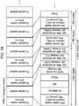
- Fig. 1 is a diagram illustrating the structure of an SD-DVD. As shown in the lower tier in Fig. 1 , the DVD disc has a logical address space provided between a read-in and a read-out. Volume information of a file system is recorded from the beginning of the logical address space, and after that is recorded application data such as video, audio, and so forth.
- the file system is an arrangement for managing data, that is stipulated by Standards such as ISO9660, Universal Disc Format (UDF), and so forth, and is an arrangement to express data on the disc in increments called directories or files.
- FAT File Allocation Tables
- NTFS NT File System
- Data recorded in the DVD can be viewed through the UDF bridge as directories or files such as illustrated to the upper left in Fig. 1 .
- a directory called “VIDEO_TS” Immediately below the root directory ("ROOT" in Fig. 1 ) is placed a directory called “VIDEO_TS”, and it is here that DVD application data is recorded.
- Application data is recorded as multiple files, primary files being the following types of files.
- IFO is a suffix indicating that the file has play control information recorded therein
- VOB is a suffix indicating that the file has an MPEG stream, which is AV data, recorded therein.
- Play control information is information attached to the AV data, such as information to realize interactivity employed with the DVD (technology to dynamically change playing in response to user operations), metadata. and so forth. Play control information is commonly referred to as navigation information regarding DVDs.
- the play control information files include the "VIDEO_TS.IFO” that manages the entire disc, and the "VTS_01_0.IFO” that is play control information for individual video title sets. Note that multiple titles, in other words, multiple different movies and tunes, can be recorded in a single disc in the case of DVD.
- the upper right portion in Fig. 1 is DVD navigation space in the application layer of the DVD, and is the logical structure space where the aforementioned play control information is loaded.
- Information within the "VIDEO_TS.IFO” is loaded in the DVD navigation space as VIDEO Manager Information (VMGI), as well as are "VTS_01_0.IFO” and play control information existing for each of other video title sets as Video Title Set Information (VTSI).
- VIDEO Manager Information VMGI
- VTS_01_0.IFO Video Title Set Information
- PGCI Program Chain Information
- PLC Program Chain
- a Cell itself is information indicating a partial section or a whole section of a VOB (short for Video Object, and indicates an MPEG stream), and playing a Cell means to play the section of this VOB instructed by the Cell.
- Commands are processed by a virtual machine of the DVD, and are close to Java (a registered trademark) Script and so forth executed in browsers to display Web pages, for example.
- Java (registered trademark) Script performs window or browser control (e.g., opening a new browser window, etc.) besides logical operations
- DVD command differ in that they only execute playback control of AV titles, e.g., instructing a chapter to play or the like, for example, besides logical operations.
- a Cell has the start and end addresses (logical addresses) of a VOB recorded in the disc as internal information thereof.
- a player reads out data using the start and end address information of the VOB described in the Cell, and executes playback.
- Fig. 2 is an overview for describing navigation information embedded in an MPEG stream, which is AV data.
- Interactivity which is a feature of the SD-DVD, is realized not only by the navigation information recorded in the aforementioned "VIDEO_TS.IFO” and “VTS_01_0.IFO” and so forth.
- Several important sets of information are multiplexed in the VOB along with video and audio data, using a dedicated carrier called navigation packs (called navi-pack or NV_PCK).
- buttons are shown on the menu screen, with processing to be executed defined for each button when that button is selected.
- One button is selected on the menu screen (a translucent color is overlaid on the selected button in highlight that button, indicating to the user that button is in a selected state), and the user can move the button in the selected state to any of the buttons above or below, to the left or to the right, using arrow keys on a remote controller.
- Fig. 2 shows an overview of information stored in an NV_PCK. Highlight color information, information of individual buttons, and so forth, are included in the NV_PCK. Color palette information is described in the highlight color information, specifying the highlight translucent color to be displayed overlaid.
- buttons Described in the button information are rectangular region information which is the position information of each button, moving information from that button to other buttons (specification of destination buttons corresponding to each operation of the arrow keys by the user), and button command information (a command to be executed when that button is okayed).
- the highlight on the menu screen is created as an overlaid image, as illustrated to the upper right portion in Fig. 2 .
- the overlaid image is an object where rectangular region information of button information has been given color in color palette information. This overlaid image is composited with the background image illustrated at the right portion in Fig. 2 , and displayed on the screen.
- the menu screen of a DVD is realized as described above.
- the reason why part of the navigation data is embedded in the stream using an NV_PCK is as follows.
- Another major reason is to improve user operability, such as to store information for supporting special playback in an NV_PCK, so that AV data can be decoded and played smoothly during non-normal playback, such as fast-forward and fast-rewind while playing the DVD.
- Fig. 3 is a schematic diagram illustrating the configuration of a VOB in a DVD.
- Data such as video, audio, and subtitles ((1) in Fig. 3 ) are packetized and packed according to the MPEG system (ISO/IEC13818-1) Standard ((2) in Fig. 3 ), and these are multiplexed to form a single MPEG program stream ((3) in Fig. 3 ), as illustrated in Fig. 3 .
- MPEG system ISO/IEC13818-1 Standard
- NV_PCKs including button commands for realizing interactivity are also multiplexed along with these, as described above.
- a feature of multiplexing in the MPEG system is that the individual pixels of data that are multiplexed are in a bit string based on decoding order, but the bit string is not necessarily formed in playback order, that is to say decoding order, among the multiplexed data, i.e., among the video, audio, and subtitles.
- decoder buffers have different sized according to each of the individual elementary streams, having 232 kB for video, 4 kB for audio, and 52 kB for subtitles.
- the data input timing to each decoder buffer differs among the individual elementary streams, so there is discrepancy between the order of forming the bit string as the MPEG system stream, and the timing of displaying (decoding).
- the subtitle data multiplexed along with the video data is not necessarily decoded at the same time.
- Blu-ray (registered trademark) disc there is a possibility that extremely high-definition video information can be stored.
- Blu-ray (registered trademark) disc is also called BD or BD-ROM.
- video information such as 4K (video information having resolution of 3840 ⁇ 2160 pixels) or HDR (high-luminosity video information, generally called High Dynamic Range) may be stored in a BD.
- HDR high-luminosity video information, generally called High Dynamic Range
- there are various methods to express luminosity including HDR and there has been no format that can record and manage video information of these realization methods efficiently as a video stream. Accordingly, there is a problem that the playback device cannot suitably express luminosity according to the type of video stream recorded in the recording medium such as the BD (the above-described realization method).
- a playback device reads out a video stream, which is encoded video information, from a recording medium, and plays the video stream.
- the playback device includes: an attribute readout unit that reads out first attribute information, indicating whether a dynamic range of luminance of the video stream is a first dynamic range or a second dynamic range that is wider than the first dynamic range, from a management information file recorded in the recording medium in a manner correlated with the video stream; a decoding unit that generates decoded video information by reading the video stream out from the recording medium and decoding the video stream; and an output unit that, in a case where the first attribute information that has been read out indicates the second dynamic range, outputs the decoded video information, along with maximum luminance information indicating a maximum luminance of the video stream in accordance with the second dynamic range.
- luminance according to the type of video stream recorded in the recording medium (particularly, the dynamic range) can be appropriately expressed.
- the first attribute information may also indicate the type of the second dynamic range
- the output unit may output the maximum luminance information and the decoded video information in accordance with the type of the second dynamic range.
- the output unit outputs the maximum luminance information where the maximum luminance is statically indicated, and the decoded video information.
- the output unit outputs the maximum luminance information where the maximum luminance is statically and dynamically indicated, and the decoded video information.
- the maximum luminance information statically indicates the luminance range by indicating a luminance range defined by the maximum luminance of all pictures in the video stream, and dynamically indicates the luminance range by indicating a luminance range for each of groups made up of one or a plurality of pictures included in the video stream, the luminance range being defined by the maximum luminance of the group.
- the decoding unit generates the decoded video information by decoding the video stream as the enhanced video stream, and further reads out the base video stream from the recording medium and decodes the base video stream to generate the base video Information, and the output unit outputs the maximum luminance information and the decoded video information subjected to image processing using the base video information
- luminance can be suitably expressed in accordance with the type of the video stream, regardless of what type of video stream is recorded in the recording medium.
- luminance can be suitably expressed in accordance with that realization method.
- the attribute readout unit may further read out second attribute information indicating the maximum luminance of the video stream from the management information file, and the output unit may further output the maximum luminance information including the second attribute information.
- the luminance of the video stream can be expressed even more appropriately.
- a recording medium has recorded therein a video stream that is encoded video information, and a management information file correlated with the video stream.
- the management information file includes first attribute information, indicating whether a dynamic range of luminance of the video stream is a first dynamic range or a second dynamic range that is wider than the first dynamic range.
- the playback device can be made to appropriately express luminance in accordance with the type of the video stream.
- HDR video streams of different realization methods can be efficiently recorded and managed in the same recording medium.
- the first attribute information may also indicate the type of the second dynamic range.
- the first attribute information indicates a first type where the luminance range of the video stream is statically expressed, as the type of the second dynamic range.
- the first attribute information indicates a second type where the luminance range of the video stream is statically and dynamically expressed, as the type of the second dynamic range.
- the luminance range of the video stream is statically expressed by including in the video stream first supplemental extension information indicating the maximum luminance of all pictures in the video stream, and the luminance range of the video stream is dynamically expressed by including in the video stream second supplemental extension information indicating, for each of groups made up of one or a plurality of pictures included in the video stream, the luminance range being defined by the maximum luminance of the group.
- the first attribute information indicates a third type, where luminance is expressed by a base video stream, and an enhanced video stream which is a video stream to enhance luminance of the base video stream, as the type of the second dynamic range, and the recording medium further has recorded therein the base video stream.
- the playback device can be made to appropriately express luminance in accordance with the type of the video stream, regardless of what type of video stream is recorded in the recording medium.
- the playback device can be made to appropriately express luminance in accordance with that realization method.
- the management information file may further include second attribute information indicating the maximum luminance of the video stream.
- the playback device can be made to appropriately express luminance in accordance with the type of the video stream.
- the second embodiment is the closest to the disclosure in Claim 1 of the present application, the basic configuration of the information recording medium and so forth in the second embedment will be described first by way of the first embodiment, to facilitate understanding.
- Fig. 4 is a diagram illustrating data hierarchy on a BD-ROM.
- a BD-ROM 104 that is a disc medium
- AV data 103 AV data 103
- BD management information 102 such as management information relating to the AV data, AV playback sequence, and so forth
- BD playback program 101 that realizes interactivity.
- BD-ROM BD-ROM
- description of BD-ROM will be made primarily with regard to an AV application that plays AV contents such as movies, but a BD-ROM can be used as a recording medium for computer use, in the same way as with CR-ROMs and DVD-ROMs, as a matter of course.
- Fig. 5 is a diagram illustrating the structure of logical data recorded on the above BD-ROM 104.
- the BD-ROM 104 has a recording region in the form of a spiral from the inner perimeter thereof toward the outer perimeter, and has a logical address space where logical data can be recorded, between a read-in at the inner perimeter and a read-out at the outer perimeter, in the same way as with other optical discs, such as DVDs and CDs, for example.
- BCA Burst Cutting Area
- Application data such as video data and the like is recorded the logical address space, with file system information (volume) at the beginning thereof.
- the file system is the arrangement for managing data stipulated by a standard such as UDF or ISO9660 or the like, as described above in the conventional art.
- Logical data recorded therein can be read out using the directory and file structure, in the same way as with a normal PC.
- the directory and file structure on the BD-ROM 104 has a BDVIDEO directory immediately below the root directory (ROOT).
- This directory is a directory in which data, such as AV data and management information handled by the BD-ROM (the BD playback program 101, BD management information 102, and AV data 103 illustrated in Fig. 4 ) is recorded.
- BD management information is a file in which is recorded information relating to the entire BD-ROM.
- the BD-ROM player reads out this file first.
- BD playback programs This is one of "BD playback programs", and is a file in which is recorded a program relating to the entire BD-ROM.
- BD management information is a file in which is recorded playlist (Play List) information that records a scenario.
- Each playlist has one file.
- the correlation to the playlist is identified by the file body name ("XXX" matches).
- VOB This is one of "AV data", and is a file in which is recorded a VOB (the same as the VOB described in the conventional example).
- VOB corresponds to one file.
- BD management information is a file in which is recorded management information relating to the VOB which is AV data.
- the correlation to the VOB is identified by the file body name ("YYY" matches).
- AV data is a file in PNG (an image format standardized by the World Wide Web Consortium (W3C) and is pronounced "ping") which is image data for configuring subtitles and menu screens.
- PNG an image format standardized by the World Wide Web Consortium (W3C) and is pronounced "ping" which is image data for configuring subtitles and menu screens.
- PNG image corresponds to one file.
- Fig. 6 is a schematic diagram illustrating the basic configuration of a BD-ROM player that plays the BD-ROM 104.
- the BD-ROM player illustrated in Fig. 6 reads out data on the BD-ROM 104 via an optical pickup 202.
- the data that is read out is stored in dedicated memory in accordance with the type of each data.
- the BD playback program (“BD.PROG” or "XXX.PROG” file) is recorded in program recording memory 203, the BD management information ("BD.INFO”, “XXX.PL”, or “YYY.VOBI” file) in management information recording memory 204, and AV data (“YYY.VOB” or “ZZZ.PNG” file) in AV recording memory 205, respectively.
- the BD playback program recorded in the program recording memory 203 is processed by a program processing unit 206.
- the BD management information recorded in the management information recording memory 204 is processed by a management information processing unit 207.
- the AV data recorded in the AV recording memory 205 is processed by a presentation processing unit 208.
- the program processing unit 206 receives information of a playlist to be played from and event information such as the timing to execute a program from the management information processing unit 207, and performs processing of the program.
- the playlist to play can be dynamically changed at the program, and this can be realized by sending a play command of the playlist after changing to the management information processing unit 207.
- the program processing unit 206 further accepts events from the user, such as requests from a remote controller that the user operates for example, and in a case where there is a program corresponding to the user event, executes the processing.
- the management information processing unit 207 receives instructions from the program processing unit 206 and analyzes a playlist corresponding to that instruction and the management information of a VOB corresponding to that playlist. Further, instructions of AV data to be played are given to the presentation processing unit 208.
- the management information processing unit 207 also receives reference time information from the presentation processing unit 208, and performs stopping instruction of the AV data playback to the presentation processing unit 208 based on the time information. Further, an event is generated indicating the program executing timing as to the program processing unit 206.
- the presentation processing unit 208 has decoders corresponding to each data of video, audio, and subtitles, and decodes and outputs AV data in accordance with instructions from the management information processing unit 207.
- the video data and subtitle data is drawn on respective dedicated planes after decoding.
- the video data is drawn on a video plane 210, and image data such as subtitle data is drawn on an image plane 209, further, compositing processing of the video drawn on the two planes is performed by a compositing processing unit 211 and output to a display device such as a TV or the like.
- the BD-ROM player has a configuration based on the data structure recorded in the BD-ROM 104 illustrated in Fig. 4 , as illustrated in Fig. 6 .
- Fig. 7 is a block diagram detailing the configuration of the player illustrated in Fig. 6 .
- the correlation of the components illustrated in Fig. 6 and the components illustrated in Fig. 7 is as follows.
- the AV recording memory 205 corresponds to image memory 308 and a track buffer 309.
- the program processing unit 206 corresponds to a program processor 302 and a UO (User Operation) manager 303.
- the management information processing unit 207 corresponds to a scenario processor 305 and a presentation controller 306.
- the presentation processing unit 208 corresponds to a clock 307, a demultiplexer 310, an image processor 311, a video processor 312, and a sound processor 313.
- the VOB data (MPEG stream) read out from the BD-ROM 104 is recorded in the track buffer 309, and the image data (PNG) in the image memory 308.
- the demultiplexer 310 extracts VOB data recorded in the track buffer 309, based on the time obtained from the clock 307. Further, video data included in the VOB data is sent to the video processor 312, and the audio data to the sound processor 313.
- the video processor 312 and sound processor 313 each are configured including a decoder buffer and a decoder, as stipulated by the MPEG system standard. That is to say, the data of each of the video and audio sent from the demultiplexer 310 is temporarily recorded in the respective decoder buffers, and subjected to decoding processing at the respective decoders following the clock 307.
- the scenario processor 305 first receives the time information from the clock 307, and instructs the presentation controller 306 to display or not display subtitles when the subtitle display time (starting and ending) arrives, so that appropriate subtitle display can be performed.
- the image processor 311 which has received a decode/display instruction from the presentation controller 306 extracts the corresponding PNG data from the image memory 308, decodes, and draws on the image plane 209.
- the decoding timing is instructed by the program processor 302.
- the program processor 302 instructs decoding of the image is dependent on the BD program that the program processor 302 is processing, and accordingly is not always the same.
- the image data and video data is drawn on the image plane 209 and video plane 210 after the respective decoding described in Fig. 6 , and composited and output by the compositing processing unit 211.
- the management information read out from the BD-ROM 104 (scenario and AV management information) is recorded in the management information recording memory 204, but the scenario information ("BD.INFO” and "XXX.PL”) is read out and processed by the scenario processor 305. Also, the AV management information (“YYY.VOBI”) is read out and processed by the presentation controller 306.
- the scenario processor 305 analyzes the playlist information, instructs the presentation controller 306 of the VOB referenced by the playlist and the playback position thereof.
- the presentation controller 306 analyzes the management information ("YYY.VOBI") of the VOB to be handled, and instructs a drive controller 317 to read out the VOB to be handled.
- the drive controller 317 follows the instructions of the presentation controller 306 to move the optical pickup 202, and read out the AV data to be handled.
- the AV data that has been read out is recorded in the image memory 308 or track buffer 309, as described earlier.
- the scenario processor 305 monitors the time of the clock 307, and hands the event to the program processor 302 at the timing set in the management information.
- the BD program recorded in the program recording memory 203 ("BD.PROG” or "XXX.PROG") is executed by the program processor 302.
- the program processor 302 processes a BD program in a case where an event has been sent from the scenario processor 305 or a case where an event has been sent from the UO manager 303.
- the UO manager 303 In a case where a request has been sent from the user by a remote controller key, the UO manager 303 generates an event corresponding to this request, and sends to the program processor 302.
- Playback of a BD-ROM is performed by the operations of the components in this way.
- Fig. 8 is a diagram illustrating application space of a BD-ROM.
- a playlist is one playback unit.
- a playlist has a static scenario that is made up of a playback sequence of cells (Cell), and a dynamic scenario described by a program.
- the playlist is simply playing the individual cells in order, and playback of the playlist ends at the point that playback of all cells has ended.
- a program is capable of describing playback beyond the playlist, and dynamically changing the object of playback in accordion with user selections or the state of the player.
- a typical example is dynamic change of the object of playback made via the menus screen.
- a menu is a scenario played by user selection, i.e., one component of a function to dynamically select a playlist.
- program means an event handler executed by a time-based event or a user event.
- a time-based event is an event generated based on time information embedded in the playlist.
- An event sent from the scenario processor 305 to the program processor 302 as described in Fig. 7 corresponds to this.
- the program processor 302 Upon a time-based event being issued, the program processor 302 process execution of an event handler correlated by ID.
- a program to be executed may instruct playback of another playlist, and in this case, the playback of the playlist currently being played is canceled, and transitions to playback of the specified playlist.
- a user event is an event generated by operations of remote controller keys by the user. There are two general types of user events. A first is an event of selecting a menu generated by operations of cursor keys ("up”, “down”, “left”, and “right” keys) and an "OK" key that the remote controller has.
- the event handler corresponding to the event of menu selection is only valid for restricted time within the playlist. That is to say, validity periods are set for each of the event handles, as playlist information.
- the program processor 302 searches for a valid event handler when an "up”, “down”, “left”, “right”, or "OK” key has been pressed, and in a case where there is a valid event handler, the event handler is executed. Otherwise, the event of menu selection is ignored.
- the second user event is an event for calling up a menu screen generated by operation of a "menu" key.
- a menu screen call-up event is generated, a global event handler is called.
- a global event handler is an event handler that is not dependent on any playlist, and is constantly valid. Using this function enables a DVD menu call to be implemented. Implementing a menu call enables audio and subtitle menus and so forth to be called up during playback of a title, and to execute playback of the title from the paused point where the audio or subtitles was changed.
- a cell which is a unit making up a static scenario in the playlist, is a reference to all or part of a playback section of a VOB (MPEG stream).
- a cell has information of starting and ending time of the playback section within the VOB.
- VOB management information VOBI
- TM time map
- TM time map
- Fig. 9 is a diagram illustrating the configuration of an MPEG stream (VOB) used in the present embodiment.
- a VOB is made up of multiple Video Object Units (VOBU).
- VOBU is a unit based on a Group Of Pictures (GOP) in a MPEG video stream, and is one playback unit in a multiplexed stream including audio data.
- GOP Group Of Pictures
- a VOBU has playback time of 0.4 seconds to 1.0 seconds, and normally has playback time of 0.5 seconds. This is due to the MPEG GOP structure normally being 15 frames/second (in the case of NTSC).
- a VOBU has a video pack (V_PCK) that is video data and an audio pack (A_PCK) that is audio data therein.
- V_PCK video pack
- A_PCK audio pack
- Each pack is configured of 1 sector, and in the case of the present embodiment is configured in 2 kB units.
- Fig. 10 is a diagram illustrating the configuration of a pack in an MPEG stream.
- Elementary data such as video data and audio data are sequentially input from the beginning of a data storage region in a packet, called a payload, as illustrated in Fig. 10 .
- a packet header is attached to a payload, making up one packet.
- an ID for identifying which stream the data stored the payload belongs to, whether video data or audio data, and in a case there are multiple streams worth of video data or audio data, which stream the data belongs to, and a Decode Time Stamp (DTS) and Presentation Time Stamp (PTS) that are timestamps for the decoding and displaying time information of this payload.
- DTS Decode Time Stamp
- PTS Presentation Time Stamp
- a header (pack header) is further added to the packet, thereby making up a pack.
- the pack header has recorded therein a System Clock Reference (SCR) that is a timestamp indicating when this pack passes through the demultiplexer 310 and is to be input to decoder buffers of the individual elementary streams.
- SCR System Clock Reference
- Fig. 11 is a diagram for describing the relationship between the AV data and the configuration of a BD-ROM player.
- the drawing at the upper tier in Fig. 11 is part of the player configuration diagram described above with reference to Fig. 7 .
- the data in the BD-ROM is passes through the optical pickup 202 and is input to the track buffer 309 if a VOB, i.e., an MPEG stream, and input to the image memory 308 if a PNG, i.e., image data.
- VOB i.e., an MPEG stream
- the track buffer 309 is a First-In First-Out (FIFO), with input VOB data being sent to the demultiplexer 310 in the order in which it was input. At this time, the individual packs are extracted from the track buffer 309 according to the aforementioned SCR, and data is delivered to the video processor 312 or sound processor 313 via the demultiplexer 310.
- FIFO First-In First-Out
- image data which image to draw is instructed by the presentation controller 306 (see Fig. 7 ).
- the image data used for drawing is deleted from the image memory 308 at the same time if image data for subtitles, but is retained in the image memory 308 if image data for a menu.
- the drawing at the lower tier in Fig. 11 is a diagram illustrating interleaved recording of a VOB file and PNG files on the BD-ROM.
- AV data that is a series of continuous playing units is recorded continuously. As long as the data is recorded continuously, all the drive has to do is to sequentially read out the data and deliver it to the player side.
- One way of reading out subtitle data is to read out all subtitle image data (PNG file) before starting playback of the VOB.
- PNG file subtitle image data
- VOB file is divided into several blocks, and the VOB file and image are subjected to interleaved recording is employed with the present embodiment.
- the lower tier in Fig. 11 is a diagram for describing interleaved recording.
- image data can be stored in the image memory 308 at a necessary timing, without the great amount of temporary recording memory described above.
- Fig. 12 is a diagram for describing a VOB data continuous supply model using the track buffer 309, to solve the above problem in interleaved recording.
- VOB data is temporarily stored in the track buffer 309. Setting the data input rate to the track buffer 309 to be higher than the data output rate from the track buffer 309 means that the amount of data sorted in the track buffer 309 continues to increase, as long as data is being read out from the BD-ROM.
- the input rate to the track buffer 309 is denoted by Va
- the output rate from the track buffer 309 is denoted by Vb.
- the continuous recording region of the VOB continues from “a1" to "a2” as illustrated in the drawing at the upper tier in Fig. 12 . From “a2" to “a3” is a section where image data is recorded, so VOB data cannot be read out.
- the drawing at the lower tier in Fig. 12 is a diagram illustrating the stored amount in the track buffer 309.
- the horizontal axis represents time, and the vertical axis represents the amount of data sorted inside the track buffer 309.
- the time “t1" indicates the time at which readout of the continuous recording region of the VOB "a1" has started.
- Time “t2" is the time to read in data at "a2", and is the end point of one continuous recording region.
- image data continues until the address "a3" on the BD-ROM, so input to the track buffer 309 is 0, and the amount of data within the track buffer 309 decreases at an output rate "-Vb". This reduction in data amount continues until the readout position "a3", i.e., until the time "t3".
- the array of image data should be decided so as to satisfy (Expression 2).
- navigation data (BD management information) recorded in the BD-ROM will be described with reference to Fig. 13 through Fig. 19 .
- Fig. 13 is a diagram illustrating the internal structure of a VOB management information file ("YYY.VOBI").
- the VOB management information has stream attribute information (Attribute) and a time map (TMAP) of this VOB.
- the stream attribute information is of a configuration having video attributes (Video) and audio attributes (Audio#0 through Audio#m) individually.
- Video video attributes
- Audio#0 through Audio#m audio attributes
- the VOB can have multiple audio streams at the same time, so the number of data fields of the audio attributes is identified by the number of audio streams (Number).
- Video Video
- values which each can have are examples of fields that the video attributes (Video) have, and values which each can have.
- the time map (TMAP) is a table having information for each VOBU, and holds the number of VOBUs (Number) that the VOB has, and each VOBU information (VOBU#1 through VOBU#n).
- Each VOBU information has a playtime length (Duration) of the VOBU and data size (Size) of the VOBU.
- Fig. 14 is a diagram for describing the details of VOBU information.
- Audio Code number 3 (AC3) that is an audio compression standard performs compression at a fixed bitrate, so the relationship between time and address can be obtained by a primary expression.
- each frame has a fixed display time such as 1/29.97 seconds in the case of NTSC for example, but the data size of each frame after compression will vary greatly depending on the picture properties and the picture type used in compression, which are the so-called I/P/B pictures.
- TMAP time map
- TMAP time map
- TMAP time map
- Fig. 15 is a diagram for describing an address acquisition method using a time map.
- time information (Time) is provided, as illustrated in Fig. 15 , first, to which VOBU that time belongs is searched for. Specifically, the number of frames is added for each VOBU in the time map, and the VOBU where the sum of the number of frames exceeds or matches the value obtained by converting this time into the number of frames is the VOBU that corresponds to this time.
- the size for each VOBU in the time map are added up to the VOBU immediately preceding this VOBU, and that values is the beginning address (Address) of the pack to be read out to play the frame including the time that has been given.
- an address corresponding to given time information can be obtained in an MPEG stream.
- Fig. 16 is a diagram illustrating the configuration of a playlist.
- a playlist is made up of a cell list (CellList) and event list (EventList).
- a cell list (CellList) is information indicating the playback cell sequence within the playlist, and cells are played in the order of description in this list.
- CellList The content of a cell list (CellList) is the number of cells (Number) and information of each cell (Cell#1 through Cell#n).
- the information of each cell has the VOB filename (VOBName), the valid section start time (In) and valid section end time (Out) in this VOB, and a subtitle table (SubtitleTable).
- VOBName VOB filename
- In valid section start time
- Out valid section end time
- SubtitleTable subtitle table
- the valid section start time (In) and valid section end time (Out) are each expressed by frame No. within this VOB, and the address for VOB data necessary for playback can be obtained by using the above-described time map (TMAP).
- the subtitle table is a table having subtitle information that is synchronously played with this VOB.
- the subtitles may have multiple languages, in the same way as with the audio.
- the subtitle table (SubtitleTable) is made up of the number of languages (Number) and a subsequent table for each language (Language#1 through Language#k).
- the table for each language is made up of language information (Language), the number of pieces of subtitle information of the subtitles to be displayed (Number)
- the subtitle information of the subtitles to be displayed (Speech#1 through Speech#j).
- Each subtitle information (Speech#1 through Speech#j) is made up of a corresponding image data filename (Name), subtitle display start time (In) and subtitle display end time (Out), and subtitle display position (Position).
- the event list is a table defining events occurring within this playlist.
- the event list is made up of the number of events (Number), and following this the individual events (Event#1 through Event#m), each event (Event#1 through Event#m) being made up of event type (Type), event ID (ID), event generation time (Time), and valid period (Duration).
- Fig. 17 is a diagram illustrating the configuration of an event handler table ("XXX.PROG”) that has an event handler (time-based events, and user events for menu selection), for each playlist.
- XXX.PROG event handler table
- the event handler table contains the number of event handlers/programs that are defined (Number), and individual event handlers/programs (Program#1 through Program#n).
- BD.INFO information relating to the entire BD-ROM
- Fig. 18 is a diagram illustrating the configuration of BD.INFO which is overall BD-ROM information.
- the overall BD-ROM information is made up of a title list (TitleList) and event list (EventList) for global events.
- the title list (TitleList) is made up of the number of titles in the disc (Number), and subsequently each title information (Title#1 through Title#n).
- Each title information (Title#1 through Title#n) includes a playlist table (PLTable) and a chapter list within the title (ChapterList).
- the playlist table includes the number of playlist in the title (Number) and the playlist names (Name), i.e., the filenames of the playlists.
- the chapter list (ChapterList) is made up of the number of chapters included in this title (Number), and each chapter information (Chapter#1 through Chapter#n).
- Each chapter information (Chapter#1 through Chapter#n) has a table of cells that this chapter includes (CellTable), the cell table (CellTable) being made up of the number of cells (Number) and entry information of each cell (CellEntry#1 through CellEntry#k).
- Cell Entry information (CellEntry#1 through CellEntry#k) is described as the playlist name containing this cell and the cell No. Within the playlist.
- EventList has the number of global events (Number) and information of each global event (Event#1 through Event#m). What is noteworthy here is that the global event that is defined first is called a first event (FirstEvent), and is the event that is executed first when the BD-ROM is inserted into the player.
- Event#1 through Event#m has only the event type (Type) and ID of the event (ID).
- Fig. 19 is a diagram illustrating the structure of the global event handler table ("BD.PROG"). This table is the same in content as the event handler table described in Fig. 17 , so description thereof will be omitted.
- BD.PROG global event handler table
- Fig. 20 is a diagram illustrating an example of a time event.
- EventList the event list in the playlist
- event type (Type) is "TimeEvent”
- t1 time event generation time
- a time event having the ID "Ex1” is output from the scenario processor 305 to the program processor 302.
- the program processor 302 searches for the handler that has the ID "Ex1", and executes the relevant event handler. For example, in the case of the present embodiment, a two-button image can be drawn, or the like.
- Fig. 21 is a diagram illustrating an example of a user event due to a user having operated a menu.
- EventList the event list in the playlist
- This event is in a ready state during the period ("T1") described in the valid standard information (Duration).
- the program processor 302 hands a UO event to the scenario processor 305, and upon receiving the UO event, the scenario processor 305 searches for whether or not a valid user event exists.
- the scenario processor 305 In a case where there is a relevant user event as the result of the search, the scenario processor 305 generates a user event, and outputs to the program processor 302.
- the program processor 302 searches for an event handler having the event ID, in the case of the example illustrated in Fig. 21 for example, "Ev1 ", and executes the relevant event handler. In the case of this example, playback of playlist#2 is started.
- the generated user event does not include information regarding which remote controller key has been pressed by the user.
- the information of the remote controller key that has been selected is notified to the program processor 302 by the UO event, and is recorded and held in a register that the virtual player has.
- the program of the event handler can check the value of this register and execute branching processing.
- Fig. 22 is a diagram illustrating an example of a global event.
- EventList the event list in the overall BD-ROM information ("BD.INFO").
- An event defined as a global even i.e., an event of which the event type (Type) is "GlobalEvent" is generated only in a case where the user has operated a remote controller key.
- a UO event is generated by the UO manager 303 and output to the program processor 302.
- the program processor 302 hands the UO event to the scenario processor 305.
- the scenario processor 305 generates the relevant global event, and sends it to the program processor 302.
- the program processor 302 searches for an event handler having the event ID "menu”, and executes this event handler. For example, in the case of the example illustrated in Fig. 22 , playback of playlist#3 is started.
- menu key this is referred to simply as menu key, but there may be multiple menu keys such as on the remote controller of a player that plays DVDs. Defining an ID corresponding to each menu key enables appropriate processing to be performed as to each menu key.
- Fig. 23 is a diagram for describing the functional configuration of the program processor 302.
- the program processor 302 is a processing module that has a virtual player machine inside.
- a virtual player machine is a function model defined as a BD-ROM, and is not dependent on the implementation of each BD-ROM player. That is to say, this guarantees that the same function can be executed in every BD-ROM player.
- a virtual player machine has two major functions; programing functions and player variables.
- the player variables are stored and held in a register.
- the programming functions are based on Java (registered trademark) Script, and the following three functions are defined as BD-ROM-unique functions.
- Link function Stops the current playback, and starts playback from specified playlist, cell, and time.
- the player variables include system parameters (SPRM) indicating setting values and so forth of the player, and general parameters (GPRM) usable in general uses.
- SPRM system parameters
- GPRM general parameters
- Fig. 24 is a diagram illustrating a list of system parameters (SPRM).
- programing functions of the virtual player have been described as being based on Java (registered trademark) Script, Other programing functions may be used, such as B-Shell used in UNIX (registered trademark) OS or the like, Perl Script, and so forth, instead of Java (registered trademark) Script.
- programing language in the present disclosure is not restricted to Java (registered trademark) Script.
- Fig. 25 and Fig. 26 are diagrams illustrating an example of a program in the event handler.
- Fig. 25 is a diagram illustrating an example of a program in an event handler according to control of a menu screen having two selection buttons.
- the program to the left side in Fig. 25 is executed using a time event at the beginning of cell (PlayList#1.Cell#1). "1" is set to GPRM(0) here first, which is one of the general parameters. GPRM(0) is used in this program to identify a button that is selected. A state where the button [1] situated on the left side has been selected is held as the initial state.
- buttons [1] and button [2] are drawn as a PNG image "1black.png” with coordinates (10, 200) as the origin (upper left end).
- the button [2] is drawn as a PNG image "2white.png” with coordinates (330, 200) as the origin (upper left end).
- Fig. 26 is a diagram illustrating an example of a program in an event handler according to a user event for selection of a menu.
- GPRM(0) is reset to 2, and the button in the selected state is changed to the button[2] at the right.
- Fig. 27 is a flowchart illustrating the basic flow of playback of AV data in a BD-ROM player.
- BD-ROM Upon a BD-ROM being inserted (S101), the BD-ROM player reads in and analyzes "BD.INFO” (S102), and reads in "BD.PROG” (S103). "BD.INFO” and “BD.PROG” are both temporarily stored in the management information recording memory 204, and analyzed by the scenario processor 305.
- the scenario processor 305 generates the first event, in accordance with the first event (FirstEvent) information in the "BD.INFO" file (S104).
- the generated first event is received by the program processor 302, which executes the event handler corresponding to this event (S105).
- the event handler corresponding to the first event will have recorded therein information specifying a playlist to play first. If no playlist to play first is instructed, the player has nothing to play, and simply awaits a user event to accept (No in S201).
- the UO manager 303 Upon receiving a remote controller operation from the user (Yes in S201), the UO manager 303 generates a UO event for the program processor 302 (S202).
- the program processor 302 determines whether or not the UO event is due to the menu key (S203), and in the case of the menu key (Yes in S203), hands the UO event to the scenario processor 305, and the scenario processor 305 generates a user event (S204).
- the program processor 302 executes the event handler corresponding to the generated user event (S205).
- Fig. 28 is a flowchart illustrating the flow of processing in a BD-ROM player from starting to play a playlist until ending the VOB.
- playback of a playlist is started by the first event handler or global event handler (S301).
- the scenario processor 305 reads in and analyzes the playlist "XXX.PL" as necessary information to play a playlist that is the object of playback (S302), and reads in the program information "XXX.PROG” corresponding to the playlist (S303).
- the scenario processor 305 starts playback of the cell, based on the cell information registered in the playlist (S304).
- Cell playback means that a request is issued from the scenario processor to the presentation controller 306, and the presentation controller 306 starts AV data playback (S305).
- the presentation controller 306 reads in the VOB information file "XXX.VOBI” corresponding to the cell being played (S402) and analyzes it.
- the presentation controller 306 identifies the VOBU for which to start playback and the address thereof, using the time map, and instructs the drive controller 317 of the readout address.
- the drive controller 317 reads out the relevant VOB data "YYY.VOB” (S403).
- VOB playback is continued until the playback section of this VOB ends (S405), and upon ending, if there is a next cell (Yes in S406), transitions to playback of Cell (S304). In a case where there is no next cell (No in S406), the processing relating to playback ends.
- Fig. 29 is a flowchart illustrating the flow of event processing from after having started AV data playback.
- the UO manager 303 In a case where there has been a UO accepted (Yes in S603), the UO manager 303 generates a UO event (S604).
- the program processor 302 accepts the UO event, and confirms whether the UO event is a menu call or not.
- the program processor 302 causes the scenario processor 305 to generate an event (S607), and the program processor 302 executes the event handler (S608).
- the scenario processor 305 determines whether or not the current time is within the valid period of the user event. If within the valid period (Yes in S606) the scenario processor 305 generates a user event (S607), and the program processor 302 executes the relevant event handler (S608).
- the user event related processing is force-quit.
- Fig. 30 is a flowchart illustrating the flow of processing of subtitle data in the BD-ROM player.
- the scenario processor 305 When playback of playlist playback is started at the BD-ROM player, confirmation is made that playlist playback has not ended (No in S702), and the scenario processor 305 confirms whether the subtitle display start time has arrived or not. In a case where the subtitle display start time has arrived (Yes in S703), the scenario processor 305 instructs the presentation controller 306 to draw the subtitle, and the presentation controller 306 instructs the image processor 311 to draw the subtitle.
- the image processor 311 follows the instruction to draw the subtitle on the image plane 209 (S704).
- the presentation controller 306 instructs the image processor 311 to erase the subtitle.
- the image processor 311 erases the subtitle that has been drawn, in accordance with the instruction (S706).
- the subtitle related processing is force-quit.
- the BD-ROM player performs basic processing relating to BD-ROM playback based on user instructions or the BD management information recorded in the BD-ROM, and so forth.
- the second embodiment is content relating to recording or playing high-luminance (HDR: High Dynamic Range) video information with a BD.
- the second embodiment is basically based on the first embodiment, so the following description will be made primarily with regard to portions that are expanded in the second embodiment or portions that are different.
- Fig. 31 illustrates a method of sending high-luminance metadata using a video encoding format such as MPEG-4 AVC (also known as H264) or HEVC (also known as H265).
- a unit made up of a picture reference configuration equivalent to a GOP (Group Of Pictures) used to improve random accessibility in MPEG-2 Video is used as a GOP in MPEG-4 AVC or HEVC, thereby encoding multiple pictures that have been grouped.
- Fig. 31 (a) indicates the encoding order of multiple NAL units in the first picture (first access unit) in the GOP.
- the first picture in the GOP there is a run of NALs of each of one AU delimiter, one SPS, one or more PPS, 0 or multiple SEI messages, and one or more Slices making up the picture, followed if necessary by the NALs of Filler data, End of sequence, and End of stream.
- Buffering period SEI message is followed by several other SEI messages if necessary.
- SEI messages including (1) a User data unregistered SEI message (GOP) indicating the reference relationship of pictures within this GOP, (2) a User data unregistered SEI message (CC) indicating the Closed Captioning information of this picture, (3) a User data unregistered SEI message (HDRb) including standard and static high-luminance metadata indicating the luminesce range such as the maximum luminance or minimum luminance in all of the pictures in this video sequence (VOB), (4) a User data unregistered SEI message (HDRe) including dynamic high-luminance metadata that is more detailed than the SEI message (HDRb), so as to indicate the luminesce range such as the maximum luminance or minimum luminance in all of the pictures in this picture or GOP, and so forth, are encoded in this order.
- GOP User data unregistered SEI message
- CC User data unregistered SEI message
- HDRe User data unregistered SEI message
- the aforementioned SEI message (HDRb) or SEI message (HDRe) is transmitted along with the video information. This is to transmit information relating to luminesce used at the time of mastering, and to give information regarding actually what level of brightness (cd/m ⁇ 2) the luminesce value (Y) for each pixel obtained after the video information is decoded.
- the SEI message (HDRb) or SEI message (HDRe) include correlation information between luminance that the pixels have and luminesce at the time of mastering, such as, upon having decoded the video, the luminance of a pixel having a luminesce value (Y) or 1000 was 5000 cd/m ⁇ 2 when mastering.
- the maximum luminance (cd/m ⁇ 2) that can be expressed by a TV connected to the player is acquired, information for changing the dynamic range of the entire picture in the luminesce direction may be carried by the aforementioned SEI message (HDRb) or SEI message (HDRe).
- the SEI message (HDRb) is an SEI message transmitted in increments of pictures or increments of GOPs to indicate an HDR video sequence, and transmits information relating to static luminance information of the overall video sequence (VOB).
- An HDR video sequence as used here means a video sequence where a SEI message (HDRb) is recorded.
- the SEI message (HDRe) that transmits information relating to dynamic luminesce that is more detailed does not have to be recorded in the HDR video sequence, and an HDR video sequence does not have to have even one therein.
- an SEI message (HDRe) exists, it is always an SEI message encoded immediately after an SEI message (HDRb), transmitting information relating to luminance in increments of pictures or increments of GOPs.
- Fig. 31 (b) illustrates the encoding order of multiple NAL units in a picture other than the first picture in the GOP (non-first access unit).
- a picture that is not the first picture in the GOP There is a run of NALs of each of one AU delimiter, 0 or one PPS, 0 or multiple SEI messages, and one or more Slices making up the picture, followed if necessary by the NALs of Filler data, End of sequence, and End of stream.
- the SEI message (HDRb) or SEI message (HDRe) each store the above information, and is given to each picture according to the method illustrated in this Fig. 31 .
- the SEI message (HDRb) and SEI message (HDRe) are both only given to the first picture in the GOP, and are not given to pictures that are not the first in the GOP at all.
- Fig. 32 is a diagram illustrating a method of multiplexing an HDR stream including up to an SEI message (HDRe) by MPEG-2 TS.
- sequence may mean the same as a stream, or may be part of a stream.
- the processing for searching for the SEI message (HDRe) from the entire video sequence may become sluggish.
- Fig. 33 is a diagram for describing another method for multiplexing an HDR video stream including up to an SEI message (HDRe) by MPEG-2 TS.
- One picture one frame or one video access unit
- the SEI message (HDRe) information is transmitted at the time of outputting HDR video by HDMI (registered trademark)
- HDRe SEI message
- Fig. 34 is a diagram for describing another method for multiplexing an HDR video stream including up to an SEI message (HDRe) by MPEG-2 TS.
- One picture one frame or one video access unit
- Fig. 35 is a diagram for describing another method for multiplexing an HDR stream including up to an SEI message (HDRe) by MPEG-2 TS.
- the difference as to the method illustrated in Fig. 34 is that the transport_priority of the TS packet storing the PES packet containing the SEI message (HDRe) is 0 in the method illustrated in Fig. 35 .
- the PID demultiplexer of the TS decoder separates the stream based on the transport_priority value. Accordingly, a decoder that is not compatible with SEI message (HDRe) and performs high-luminance-izing using information up to the SEI message (HDRb) can easily discard the TS packet including the SEI message (HDRe) by the aforementioned PID demultiplexer.
- Fig. 36 is a diagram for describing another method for multiplexing an HDR stream including up to an SEI message (HDRe) by MPEG-2 TS.
- the method illustrated in Fig. 36 uses two types of PID as in the method illustrated in Fig. 33 , and configures the PES packets as in the method illustrated in Fig. 34 and Fig. 35 .
- This method illustrated in Fig. 36 has both the same advantages and disadvantages as the method illustrated in Fig. 33 .
- Fig. 37 is a diagram for describing another method for multiplexing an HDR stream including up to an SEI message (HDRe) by MPEG-2 TS.
- the position of multiplexing of the SEI message (HDRe) is immediately after the picture data. Accordingly, the method illustrated in Fig. 37 stores the HDR video sequence up to the SEI message (HDRb) in one PES packet.
- the method illustrated in Fig. 37 has both the same advantages and disadvantages as the method illustrated in Fig. 33 .
- Fig. 38 is a diagram for describing a method for multiplexing an enhanced video sequence, which is a different video sequence from an HDR video sequence, by MPEG-2 TS, instead of an SEI message (HDRe).
- the method illustrated in Fig. 38 transmits an enhanced video sequence (Enhancement layer video sequence) as enhancement video information regarding an HDR video sequence (Base layer video sequence with user data unregistered SEI message (HDRb)), instead of transmitting high-luminance enhancement metadata by SEI message (HDRe).
- an enhanced video sequence Enhancment layer video sequence
- HDRb Base layer video sequence with user data unregistered SEI message
- an enhanced picture of Enhancement frame PES#n included in the enhanced video sequence is added to the base picture of Base frame PES#n included in the above-described video sequence. Accordingly, high-luminance enhancement of the HDE video sequence can be performed more accurately while using even more data than the SEI message.
- the above-described base video sequence and enhanced video sequence are multiplied in the MPEG-2 TS as two entirely different video sequences in PES packets with different PIDs.
- the PMT packet may express the pair using descriptor().
- this method illustrated in Fig. 38 describes HDR_pairing descriptor() in the PMT packet.
- the HDR_pairing descriptor() contains the number of pairs in this MPEG-2 TS (number of HDR_pairs), and the PID values that the base video sequence and enhanced video sequence use, for each pair.
- the PID value used by the base video sequence is indicated by base_layer video sequence_PID
- the PID value used by the enhanced video sequence is indicated by enhancement_layer_video_sequence_PID. Describing the HDR_pairing descriptor() in this way enables a correct combination of pairs to be indicated.
- Fig. 39 is a diagram for describing management information in a case of managing an HDR video stream by YYY.VOBI, which is management information of a video stream (YYY.VOB).
- Video attribute information in one video stream includes not only coding method (Coding), spatial resolution (Resolution), aspect ratio (Aspect), and frame rate (Framerate), but also the following attribute information.
- Attribute information is_HDR is information for identifying whether the video stream corresponding to this attribute information is an HDR video stream, or an SDR (Standard Dynamic Range) video stream.
- SDR Standard Dynamic Range
- Attribute information HDR_type indicates the type of video stream corresponding to this attribute information, i.e., the type of HDR.
- the type of HDR i.e., the type of HDR.
- the bit one order higher (b5) is 1 b
- the bit one order higher (b4) is 1 b
- Attribute information HDR_base_stream is information that identifies an HDR video stream (base video stream) including a base SEI message (HDRb), in a case where the video stream corresponding to this attribute information is a SEI message (HDRe) luminance-enhanced HDR video stream or an enhanced video sequence.
- the information indicates the PID value of a TS packet in an HDR video stream (base video stream) including a base SEI message (HDRb). Accordingly, which video stream is the base video stream paired with the video stream corresponding to the attribute information can be known without analyzing the stream, so setting of the PID demultiplexer of the TS decoder can be appropriately performed.
- Max_luminance represents the pixel luminance value (Y) of the maximum luminance (Max_luminance) of the HDR video stream within the video stream (YYY.VOB) corresponding to the attribute information, and further represents the luminance thereof in units of cd/m ⁇ 2.
- Min_luminance represents the pixel luminance value (Y) of the minimum luminance (Min_luminance) of the HDR video stream within the video stream (YYY.VOB) corresponding to the attribute information, and further represents the luminance thereof in units of cd/m ⁇ 2.
- the player By analyzing this video attribute information, the player, which is the playback device, can determine whether the video stream to be played is HDR or not. Further, if the video stream is HDR, the player can determine what type of the HDR is, i.e., what encoding format the HDR video stream has. The player can also obtain the identification information (PID) of the base HDR video stream corresponding to the video stream to be played, and information indicating luminance range, such as maximum luminance and minimum luminance.
- PID identification information
- Fig. 40 is a diagram for describing a decoder model of an HDR video stream according to the present embodiment.
- An HDR video stream containing an SEI message (HDRb) is decoded at a base decoder (Base Dec) 401.
- the high-luminance video information generated y decoding the HDR video stream is rendered at a base plane (Base plane (HDRb)) 403.
- the basic luminance information (the luminance range defined by the maximum/minimum luminesce values of the overall contents) and so forth included in the SEI message (HDRb) is transmitted along with the high-luminance video information, and output to an external video output I/F such as HDMI (registered trademark).
- a decoder system 400 compatible with SEI messages (HDRe) adds luminance enhancement information of the SEI message (HDRe) to the high-luminance video information of the base plane (Base plane (HDRb)) 403, and renders the enhanced high-luminance video information on an HDRe plane 405.
- the enhanced high-luminance video information to which the SEI message (HDRe) is also added is output to an external video output I/F such as HDMI (registered trademark), along with additional luminance information (luminance range defined by maximum luminance value and minimum luminance value in increments of scenes) included in the SEI message (HDRe).
- the decoder system 400 compatible with the enhanced video sequence described above decodes the enhanced video sequence at an enhancement decoder (Enh. Decd) 402.
- the enhanced video information generated by this decoding is rendered to an enhancement plane (Enh. plane) 404.
- the decoder system 400 composites this enhanced video information with the high-luminance video information at the base plane (Base plane (HDRb)) 403, so as to composite videos that have the same PTS.
- the enhanced high-luminance video information obtained by this compositing is rendered to a Base+Enh. Plane 406.
- the decoder system 400 outputs this enhanced high-luminance video information to an external video output I/F such as HDMI (registered trademark), along with basic luminance information transmitted by the SEI message (HDRb), luminance enhancement information stored in the enhanced video sequence, and so forth.
- HDMI registered trademark
- HDRb basic luminance information transmitted by the SEI message
- Fig. 41A is a block diagram illustrating an example of the configuration of a playback device according to the present embodiment.
- a playback device 100 is a device that reads out video streams, which are encoded video information, from a recording medium 200 such as the above-described BD for example, and playing the video streams, including a readout unit 110, a decoding unit 120, and an output unit 130.
- the readout unit 110 reads out first attribute information, indicating whether the dynamic range of luminance of that video stream is a first dynamic range or a second dynamic range, from a management information file recorded in the recording medium 200 in a manner correlated with the video stream.
- the first dynamic range is SDR
- the second dynamic range is HDR, which is a dynamic range that is wider than SDR.
- the management information file is the above-described VOBI file, for example, and the first attribute information contained in the management information file is information made up of is_HDR and HDR_type.
- the is_HDR contained in the first attribute information indicates whether that video stream is SDR or HDR.
- the decoding unit 120 generates decoded video information by reading the video stream out from the recording medium 200 and decoding the video stream.
- This decoding unit 120 includes, for example, the base decoder 401 and enhancement decoder 402 in Fig. 40 , and so forth.
- the output unit 130 outputs the generated decoded video information, along with maximum luminance information indicating a maximum luminance of the video stream in accordance with the second dynamic range.
- This output unit 130 includes, of the components illustrated in Fig. 40 for example, the components other than the base decoder 401 and enhancement decoder 402.
- the maximum luminance information indicating a maximum luminance is information included in the above-described SEI message (HDRb), or information included in the SEI message (HDRb) and SEI message (HDRe).
- the playback device 100 can appropriately express luminance corresponding to the type of video stream (dynamic range in particular) recorded in the recording medium 200.
- the first attribute information indicates the second dynamic range
- the first attribute information further indicates the type of the second dynamic range. That is to say, the HDR_type in the first attribute information indicates the type of HDR.
- the output unit 130 outputs the maximum luminance information and decoded video information in accordance with the type of the second dynamic range.
- the output unit 130 outputs the maximum luminance information where the maximum luminance is statically indicated and the decoded video information.
- the maximum luminance information indicates the luminance range defined by the maximum luminance of all pictures in the video stream, thereby statically indicating the luminance range. That is to say, the output unit 130 outputs the information contained in the SEI message (HDRb) as the maximum luminance information.
- the output unit 130 outputs the maximum luminance information where the maximum luminance is statically and dynamically indicated, and the decoded video information.
- the maximum luminance information dynamically indicates the luminance range by indicating a luminance range for each of groups made up of one or multiple pictures included in the video stream, the luminance range being defined by the maximum luminance of the group.
- a group made up of multiple pictures is a GOP, for example. That is to say, the output unit 130 outputs the information included in the SEI message (HDRb) and SEI message (HDRe) as maximum luminance information.
- the decoding unit 120 generates the decoded video information by decoding the video stream as the enhanced video stream.
- the decoding unit 120 further reads out the base video stream from the recording medium 200 and decodes the base video stream to generate the base video Information.
- the output unit 130 outputs the maximum luminance information and the decoded video information subjected to image processing (e.g., compositing) using the generated base video information.
- the maximum luminance information output at this time is the information contained in the above-described SEI message (HDRb).
- luminance corresponding to the type of HDR video stream can be appropriately expressed, regardless of what type of HDR video stream is recorded in the recording medium 200.
- the attribute readout 110 unit further reads out second attribute information indicating the maximum luminance of the video stream, from the management information file.
- the second attribute information is the above-described Max_luminance, for example.
- the output unit 130 further outputs the maximum luminance information including the second attribute information.
- luminance of the video stream can be expressed even more appropriately.
- recorded in the recording medium 200 is the above-described video stream, and a management information containing each of the above-described attribute information.
- a base video stream is also recorded in accordance with the type of video stream.
- the recording medium 200 can cause the playback device to appropriately express luminance corresponding to the type of video stream.
- HDR video streams of the multiple realization methods could not conventionally be efficiently recorded and managed in one recording medium.
- attribute information indicating the above-described realization method is recorded for each of the multiple HDR video streams, so HDR video streams of multiple realization methods can be suitably recorded in the same recording medium. That is to say, HDR video streams of different realization methods can be effectively recorded and managed in the same media.
- a video stream can be selected in accordance with the high-luminance image display capabilities of a TV, from a single recording medium.
- Fig. 41 B is a flowchart illustrating an example of a playback method according to the present embodiment.
- the playback method is a method of reading out a video stream, which is encoded video information, from the recording medium 200, and playing the video stream, the playback method including a step S110, a step S120, and a step S130.
- step S110 first attribute information, indicating whether a dynamic range of luminance of the video stream is a first dynamic range or a second dynamic range that is wider than the first dynamic range, is read out from a management information file recorded in the recording medium 200 in a manner correlated with the video stream.
- step S120 decoded video information is generated by reading the video stream out from the recording medium 200 and decoding the video stream.
- step S130 in a case where the attribute information that has been read out indicates the second dynamic range (i.e., HDR), the decoded video information is output along with maximum luminance information indicating the maximum luminance of the video stream in accordance with the second dynamic range.
- the second dynamic range i.e., HDR
- the luminance can be appropriately expressed in accordance with the type of video stream recorded in the recording medium 200 (dynamic range in particular) recorded in the recording medium 200.
- the components may be realized by a dedicated hardware configuration, or by executing a software program suitable for the components.
- the components may be realized by a program executing unit such as a CPU or processor reading out and executing a software program recorded in a recording medium such as a hard disk or semiconductor memory or the like.
- the software that realizes the playback device 100 and so forth in the above-described embodiments is a program that causes a computer to execute the steps included in the flowchart illustrated in Fig. 41 B , for example.
- the present disclosure enables luminance to be appropriately expressed in accordance with the type of video stream recorded in a recording medium such as a BD for example, and is applicable to a playback device such as a BD player for example, and an optical disc such as a BD for example.
Priority Applications (1)
| Application Number | Priority Date | Filing Date | Title |
|---|---|---|---|
| EP21194019.2A EP3944241A3 (de) | 2014-08-07 | 2015-07-14 | Dekodierungssystem und dekodierungsverfahren |
Applications Claiming Priority (3)
| Application Number | Priority Date | Filing Date | Title |
|---|---|---|---|
| US201462034389P | 2014-08-07 | 2014-08-07 | |
| JP2015115045A JP6466258B2 (ja) | 2014-08-07 | 2015-06-05 | 再生装置、再生方法および記録媒体 |
| PCT/JP2015/003547 WO2016021120A1 (ja) | 2014-08-07 | 2015-07-14 | 再生装置、再生方法および記録媒体 |
Related Child Applications (2)
| Application Number | Title | Priority Date | Filing Date |
|---|---|---|---|
| EP21194019.2A Division-Into EP3944241A3 (de) | 2014-08-07 | 2015-07-14 | Dekodierungssystem und dekodierungsverfahren |
| EP21194019.2A Division EP3944241A3 (de) | 2014-08-07 | 2015-07-14 | Dekodierungssystem und dekodierungsverfahren |
Publications (3)
| Publication Number | Publication Date |
|---|---|
| EP3107100A1 true EP3107100A1 (de) | 2016-12-21 |
| EP3107100A4 EP3107100A4 (de) | 2017-05-31 |
| EP3107100B1 EP3107100B1 (de) | 2021-10-20 |
Family
ID=55530347
Family Applications (1)
| Application Number | Title | Priority Date | Filing Date |
|---|---|---|---|
| EP15829514.7A Active EP3107100B1 (de) | 2014-08-07 | 2015-07-14 | Wiedergabevorrichtung, wiedergabeverfahren und aufzeichnungsmedium |
Country Status (4)
| Country | Link |
|---|---|
| US (3) | US10255951B2 (de) |
| EP (1) | EP3107100B1 (de) |
| JP (2) | JP6466258B2 (de) |
| CN (2) | CN105580081B (de) |
Cited By (1)
| Publication number | Priority date | Publication date | Assignee | Title |
|---|---|---|---|---|
| EP3121815A4 (de) * | 2014-09-12 | 2017-08-02 | Panasonic Intellectual Property Corporation of America | Aufzeichnungsmedium, wiedergabevorrichtung und wiedergabeverfahren |
Families Citing this family (3)
| Publication number | Priority date | Publication date | Assignee | Title |
|---|---|---|---|---|
| WO2017179592A1 (ja) * | 2016-04-12 | 2017-10-19 | ソニー株式会社 | 送信装置、送信方法、受信装置および受信方法 |
| EP3657807A4 (de) * | 2017-07-20 | 2020-05-27 | Sony Corporation | Sendevorrichtung, sendeverfahren, empfangsvorrichtung und empfangsverfahren |
| CN114302215B (zh) * | 2021-12-29 | 2023-09-29 | 北京奕斯伟计算技术股份有限公司 | 视频数据流解码系统、方法、电子设备和介质 |
Family Cites Families (21)
| Publication number | Priority date | Publication date | Assignee | Title |
|---|---|---|---|---|
| SG109998A1 (en) * | 1996-03-06 | 2005-04-28 | Sony Corp | Image pickup apparatus and solid state image pickup device |
| JPH09282848A (ja) | 1996-04-05 | 1997-10-31 | Pioneer Electron Corp | 情報記録媒体並びにその記録装置及び再生装置 |
| CN100583955C (zh) * | 1998-07-17 | 2010-01-20 | 索尼公司 | 成像设备及图像数据处理方法 |
| US8300698B2 (en) * | 2006-10-23 | 2012-10-30 | Qualcomm Incorporated | Signalling of maximum dynamic range of inverse discrete cosine transform |
| JP4877165B2 (ja) * | 2007-09-11 | 2012-02-15 | ソニー株式会社 | モニタリングシステム |
| US20090293082A1 (en) * | 2008-05-20 | 2009-11-26 | Broadcom Corporation | Video processing system with key table and methods for use therewith |
| US8428145B2 (en) * | 2008-12-31 | 2013-04-23 | Entropic Communications, Inc. | System and method for providing fast trick modes |
| PL2465265T3 (pl) * | 2009-08-12 | 2019-07-31 | Interdigital Vc Holdings, Inc. | Sposób i urządzenie do ulepszonego wewnątrz-ramkowego kodowania i dekodowania chrominancji |
| PL2617195T3 (pl) | 2010-09-16 | 2019-08-30 | Koninklijke Philips N.V. | Urządzenia i sposoby ulepszonego kodowania obrazów |
| EP2702766B1 (de) * | 2011-04-28 | 2017-06-14 | Koninklijke Philips N.V. | Gerät und verfahren für die kodierung und die dekodierung von hdr bildern |
| EP2707868B1 (de) | 2011-05-10 | 2024-04-03 | Koninklijke Philips N.V. | Erzeugung und verarbeitung von bildsignalen mit hohem dynamischem bereich |
| WO2013038679A1 (ja) * | 2011-09-13 | 2013-03-21 | パナソニック株式会社 | 符号化装置、復号装置、再生装置、符号化方法、及び復号方法 |
| UA116082C2 (uk) * | 2011-09-27 | 2018-02-12 | Конінклійке Філіпс Н.В. | Пристрій та спосіб для перетворення динамічного діапазону зображень |
| TWI586150B (zh) * | 2012-06-29 | 2017-06-01 | 新力股份有限公司 | 影像處理裝置及非暫態電腦可讀儲存媒體 |
| KR101901124B1 (ko) * | 2013-01-02 | 2018-09-27 | 돌비 레버러토리즈 라이쎈싱 코오포레이션 | 향상된 동적 범위를 갖는 초고화질 비디오 신호들에 대한 하위 호환가능한 코딩 |
| KR102241672B1 (ko) | 2013-04-30 | 2021-04-16 | 소니 주식회사 | 송신 장치, 송신 방법, 수신 장치 및 수신 방법 |
| MY178948A (en) * | 2013-06-20 | 2020-10-23 | Sony Corp | Reproduction device, reproduction method, and recording medium |
| JP2015008360A (ja) * | 2013-06-24 | 2015-01-15 | ソニー株式会社 | 再生装置、再生方法、および記録媒体 |
| KR101797505B1 (ko) * | 2013-11-13 | 2017-12-12 | 엘지전자 주식회사 | Hdr 방송 서비스 제공을 위한 방송 신호 송수신 방법 및 장치 |
| CN110708439A (zh) * | 2014-06-26 | 2020-01-17 | 松下知识产权经营株式会社 | 显示装置及数据输出方法 |
| JP6421504B2 (ja) * | 2014-07-28 | 2018-11-14 | ソニー株式会社 | 画像処理装置及び画像処理方法 |
-
2015
- 2015-06-05 JP JP2015115045A patent/JP6466258B2/ja active Active
- 2015-07-14 EP EP15829514.7A patent/EP3107100B1/de active Active
- 2015-07-14 CN CN201580001920.8A patent/CN105580081B/zh active Active
- 2015-07-14 CN CN202010088066.6A patent/CN111276170B/zh active Active
-
2016
- 2016-09-28 US US15/278,582 patent/US10255951B2/en active Active
-
2019
- 2019-01-09 JP JP2019001572A patent/JP6724176B2/ja active Active
- 2019-01-18 US US16/251,688 patent/US10832737B2/en active Active
-
2020
- 2020-09-30 US US17/038,708 patent/US11538502B2/en active Active
Cited By (10)
| Publication number | Priority date | Publication date | Assignee | Title |
|---|---|---|---|---|
| EP3121815A4 (de) * | 2014-09-12 | 2017-08-02 | Panasonic Intellectual Property Corporation of America | Aufzeichnungsmedium, wiedergabevorrichtung und wiedergabeverfahren |
| US9852775B2 (en) | 2014-09-12 | 2017-12-26 | Panasonic Intellectual Property Corporation Of America | Recording medium, playback device, and playback method |
| US10482923B2 (en) | 2014-09-12 | 2019-11-19 | Panasonic Intellectual Property Corporation Of America | Recording medium, playback device, and playback method |
| US10482924B2 (en) | 2014-09-12 | 2019-11-19 | Panasonic Intellectual Property Corporation Of America | Recording medium, playback device, and playback method |
| US10535374B2 (en) | 2014-09-12 | 2020-01-14 | Panasonic Intellectual Property Corporation Of America | Recording medium, playback device, and playback method |
| US10535373B2 (en) | 2014-09-12 | 2020-01-14 | Panasonic Intellectual Property Corporation Of America | Recording medium, playback device, and playback method |
| US10741219B2 (en) | 2014-09-12 | 2020-08-11 | Panasonic Intellectual Property Corporation Of America | Recording medium, playback device, and playback method |
| US10789988B2 (en) | 2014-09-12 | 2020-09-29 | Panasonic Intellectual Property Corporation Of America | Recording medium, playback device, and playback method |
| EP3786953A1 (de) * | 2014-09-12 | 2021-03-03 | Panasonic Intellectual Property Corporation of America | Aufzeichnungsmedium, wiedergabegerät und wiedergabeverfahren |
| US11133035B2 (en) | 2014-09-12 | 2021-09-28 | Panasonic Intellectual Property Corporation Of America | Recording medium, playback device, and playback method |
Also Published As
| Publication number | Publication date |
|---|---|
| CN111276170A (zh) | 2020-06-12 |
| CN105580081B (zh) | 2020-03-03 |
| US11538502B2 (en) | 2022-12-27 |
| US10255951B2 (en) | 2019-04-09 |
| US20190156864A1 (en) | 2019-05-23 |
| US10832737B2 (en) | 2020-11-10 |
| EP3107100A4 (de) | 2017-05-31 |
| JP6724176B2 (ja) | 2020-07-15 |
| EP3107100B1 (de) | 2021-10-20 |
| JP2019075819A (ja) | 2019-05-16 |
| CN105580081A (zh) | 2016-05-11 |
| JP2016039627A (ja) | 2016-03-22 |
| US20170018291A1 (en) | 2017-01-19 |
| US20210012811A1 (en) | 2021-01-14 |
| JP6466258B2 (ja) | 2019-02-06 |
| CN111276170B (zh) | 2021-09-07 |
Similar Documents
| Publication | Publication Date | Title |
|---|---|---|
| US11133035B2 (en) | Recording medium, playback device, and playback method | |
| EP3208802B1 (de) | Aufzeichnungsmedium, wiedergabeverfahren und wiedergabevorrichtung | |
| US20200365190A1 (en) | Recording medium, playback method, and playback device | |
| US11538502B2 (en) | Playback device, playback method, and recording medium | |
| US11929102B2 (en) | Playback device, playback method, and recording medium | |
| EP4280598A2 (de) | Aufzeichnungsmedium, wiedergabegerät und wiedergabeverfahren |
Legal Events
| Date | Code | Title | Description |
|---|---|---|---|
| PUAI | Public reference made under article 153(3) epc to a published international application that has entered the european phase |
Free format text: ORIGINAL CODE: 0009012 |
|
| STAA | Information on the status of an ep patent application or granted ep patent |
Free format text: STATUS: REQUEST FOR EXAMINATION WAS MADE |
|
| 17P | Request for examination filed |
Effective date: 20160915 |
|
| AK | Designated contracting states |
Kind code of ref document: A1 Designated state(s): AL AT BE BG CH CY CZ DE DK EE ES FI FR GB GR HR HU IE IS IT LI LT LU LV MC MK MT NL NO PL PT RO RS SE SI SK SM TR |
|
| AX | Request for extension of the european patent |
Extension state: BA ME |
|
| REG | Reference to a national code |
Ref country code: DE Ref legal event code: R079 Ref document number: 602015074339 Country of ref document: DE Free format text: PREVIOUS MAIN CLASS: G11B0027000000 Ipc: G11B0020100000 |
|
| A4 | Supplementary search report drawn up and despatched |
Effective date: 20170504 |
|
| RIC1 | Information provided on ipc code assigned before grant |
Ipc: G11B 27/10 20060101ALI20170426BHEP Ipc: G11B 20/10 20060101AFI20170426BHEP Ipc: H04N 9/804 20060101ALI20170426BHEP Ipc: H04N 9/82 20060101ALI20170426BHEP Ipc: G11B 27/32 20060101ALI20170426BHEP Ipc: H04N 5/84 20060101ALI20170426BHEP |
|
| DAV | Request for validation of the european patent (deleted) | ||
| DAX | Request for extension of the european patent (deleted) | ||
| STAA | Information on the status of an ep patent application or granted ep patent |
Free format text: STATUS: EXAMINATION IS IN PROGRESS |
|
| 17Q | First examination report despatched |
Effective date: 20180122 |
|
| STAA | Information on the status of an ep patent application or granted ep patent |
Free format text: STATUS: EXAMINATION IS IN PROGRESS |
|
| GRAP | Despatch of communication of intention to grant a patent |
Free format text: ORIGINAL CODE: EPIDOSNIGR1 |
|
| STAA | Information on the status of an ep patent application or granted ep patent |
Free format text: STATUS: GRANT OF PATENT IS INTENDED |
|
| INTG | Intention to grant announced |
Effective date: 20210520 |
|
| GRAS | Grant fee paid |
Free format text: ORIGINAL CODE: EPIDOSNIGR3 |
|
| GRAA | (expected) grant |
Free format text: ORIGINAL CODE: 0009210 |
|
| STAA | Information on the status of an ep patent application or granted ep patent |
Free format text: STATUS: THE PATENT HAS BEEN GRANTED |
|
| AK | Designated contracting states |
Kind code of ref document: B1 Designated state(s): AL AT BE BG CH CY CZ DE DK EE ES FI FR GB GR HR HU IE IS IT LI LT LU LV MC MK MT NL NO PL PT RO RS SE SI SK SM TR |
|
| REG | Reference to a national code |
Ref country code: GB Ref legal event code: FG4D |
|
| REG | Reference to a national code |
Ref country code: CH Ref legal event code: EP |
|
| REG | Reference to a national code |
Ref country code: IE Ref legal event code: FG4D |
|
| REG | Reference to a national code |
Ref country code: DE Ref legal event code: R096 Ref document number: 602015074339 Country of ref document: DE |
|
| REG | Reference to a national code |
Ref country code: AT Ref legal event code: REF Ref document number: 1440593 Country of ref document: AT Kind code of ref document: T Effective date: 20211115 |
|
| REG | Reference to a national code |
Ref country code: LT Ref legal event code: MG9D |
|
| REG | Reference to a national code |
Ref country code: NL Ref legal event code: MP Effective date: 20211020 |
|
| REG | Reference to a national code |
Ref country code: AT Ref legal event code: MK05 Ref document number: 1440593 Country of ref document: AT Kind code of ref document: T Effective date: 20211020 |
|
| PG25 | Lapsed in a contracting state [announced via postgrant information from national office to epo] |
Ref country code: RS Free format text: LAPSE BECAUSE OF FAILURE TO SUBMIT A TRANSLATION OF THE DESCRIPTION OR TO PAY THE FEE WITHIN THE PRESCRIBED TIME-LIMIT Effective date: 20211020 Ref country code: LT Free format text: LAPSE BECAUSE OF FAILURE TO SUBMIT A TRANSLATION OF THE DESCRIPTION OR TO PAY THE FEE WITHIN THE PRESCRIBED TIME-LIMIT Effective date: 20211020 Ref country code: FI Free format text: LAPSE BECAUSE OF FAILURE TO SUBMIT A TRANSLATION OF THE DESCRIPTION OR TO PAY THE FEE WITHIN THE PRESCRIBED TIME-LIMIT Effective date: 20211020 Ref country code: BG Free format text: LAPSE BECAUSE OF FAILURE TO SUBMIT A TRANSLATION OF THE DESCRIPTION OR TO PAY THE FEE WITHIN THE PRESCRIBED TIME-LIMIT Effective date: 20220120 Ref country code: AT Free format text: LAPSE BECAUSE OF FAILURE TO SUBMIT A TRANSLATION OF THE DESCRIPTION OR TO PAY THE FEE WITHIN THE PRESCRIBED TIME-LIMIT Effective date: 20211020 |
|
| PG25 | Lapsed in a contracting state [announced via postgrant information from national office to epo] |
Ref country code: IS Free format text: LAPSE BECAUSE OF FAILURE TO SUBMIT A TRANSLATION OF THE DESCRIPTION OR TO PAY THE FEE WITHIN THE PRESCRIBED TIME-LIMIT Effective date: 20220220 Ref country code: SE Free format text: LAPSE BECAUSE OF FAILURE TO SUBMIT A TRANSLATION OF THE DESCRIPTION OR TO PAY THE FEE WITHIN THE PRESCRIBED TIME-LIMIT Effective date: 20211020 Ref country code: PT Free format text: LAPSE BECAUSE OF FAILURE TO SUBMIT A TRANSLATION OF THE DESCRIPTION OR TO PAY THE FEE WITHIN THE PRESCRIBED TIME-LIMIT Effective date: 20220221 Ref country code: PL Free format text: LAPSE BECAUSE OF FAILURE TO SUBMIT A TRANSLATION OF THE DESCRIPTION OR TO PAY THE FEE WITHIN THE PRESCRIBED TIME-LIMIT Effective date: 20211020 Ref country code: NO Free format text: LAPSE BECAUSE OF FAILURE TO SUBMIT A TRANSLATION OF THE DESCRIPTION OR TO PAY THE FEE WITHIN THE PRESCRIBED TIME-LIMIT Effective date: 20220120 Ref country code: NL Free format text: LAPSE BECAUSE OF FAILURE TO SUBMIT A TRANSLATION OF THE DESCRIPTION OR TO PAY THE FEE WITHIN THE PRESCRIBED TIME-LIMIT Effective date: 20211020 Ref country code: LV Free format text: LAPSE BECAUSE OF FAILURE TO SUBMIT A TRANSLATION OF THE DESCRIPTION OR TO PAY THE FEE WITHIN THE PRESCRIBED TIME-LIMIT Effective date: 20211020 Ref country code: HR Free format text: LAPSE BECAUSE OF FAILURE TO SUBMIT A TRANSLATION OF THE DESCRIPTION OR TO PAY THE FEE WITHIN THE PRESCRIBED TIME-LIMIT Effective date: 20211020 Ref country code: GR Free format text: LAPSE BECAUSE OF FAILURE TO SUBMIT A TRANSLATION OF THE DESCRIPTION OR TO PAY THE FEE WITHIN THE PRESCRIBED TIME-LIMIT Effective date: 20220121 Ref country code: ES Free format text: LAPSE BECAUSE OF FAILURE TO SUBMIT A TRANSLATION OF THE DESCRIPTION OR TO PAY THE FEE WITHIN THE PRESCRIBED TIME-LIMIT Effective date: 20211020 |
|
| REG | Reference to a national code |
Ref country code: DE Ref legal event code: R097 Ref document number: 602015074339 Country of ref document: DE |
|
| PG25 | Lapsed in a contracting state [announced via postgrant information from national office to epo] |
Ref country code: SM Free format text: LAPSE BECAUSE OF FAILURE TO SUBMIT A TRANSLATION OF THE DESCRIPTION OR TO PAY THE FEE WITHIN THE PRESCRIBED TIME-LIMIT Effective date: 20211020 Ref country code: SK Free format text: LAPSE BECAUSE OF FAILURE TO SUBMIT A TRANSLATION OF THE DESCRIPTION OR TO PAY THE FEE WITHIN THE PRESCRIBED TIME-LIMIT Effective date: 20211020 Ref country code: RO Free format text: LAPSE BECAUSE OF FAILURE TO SUBMIT A TRANSLATION OF THE DESCRIPTION OR TO PAY THE FEE WITHIN THE PRESCRIBED TIME-LIMIT Effective date: 20211020 Ref country code: EE Free format text: LAPSE BECAUSE OF FAILURE TO SUBMIT A TRANSLATION OF THE DESCRIPTION OR TO PAY THE FEE WITHIN THE PRESCRIBED TIME-LIMIT Effective date: 20211020 Ref country code: DK Free format text: LAPSE BECAUSE OF FAILURE TO SUBMIT A TRANSLATION OF THE DESCRIPTION OR TO PAY THE FEE WITHIN THE PRESCRIBED TIME-LIMIT Effective date: 20211020 Ref country code: CZ Free format text: LAPSE BECAUSE OF FAILURE TO SUBMIT A TRANSLATION OF THE DESCRIPTION OR TO PAY THE FEE WITHIN THE PRESCRIBED TIME-LIMIT Effective date: 20211020 |
|
| PLBE | No opposition filed within time limit |
Free format text: ORIGINAL CODE: 0009261 |
|
| STAA | Information on the status of an ep patent application or granted ep patent |
Free format text: STATUS: NO OPPOSITION FILED WITHIN TIME LIMIT |
|
| 26N | No opposition filed |
Effective date: 20220721 |
|
| PG25 | Lapsed in a contracting state [announced via postgrant information from national office to epo] |
Ref country code: AL Free format text: LAPSE BECAUSE OF FAILURE TO SUBMIT A TRANSLATION OF THE DESCRIPTION OR TO PAY THE FEE WITHIN THE PRESCRIBED TIME-LIMIT Effective date: 20211020 |
|
| PG25 | Lapsed in a contracting state [announced via postgrant information from national office to epo] |
Ref country code: SI Free format text: LAPSE BECAUSE OF FAILURE TO SUBMIT A TRANSLATION OF THE DESCRIPTION OR TO PAY THE FEE WITHIN THE PRESCRIBED TIME-LIMIT Effective date: 20211020 |
|
| PG25 | Lapsed in a contracting state [announced via postgrant information from national office to epo] |
Ref country code: MC Free format text: LAPSE BECAUSE OF FAILURE TO SUBMIT A TRANSLATION OF THE DESCRIPTION OR TO PAY THE FEE WITHIN THE PRESCRIBED TIME-LIMIT Effective date: 20211020 |
|
| REG | Reference to a national code |
Ref country code: CH Ref legal event code: PL |
|
| REG | Reference to a national code |
Ref country code: BE Ref legal event code: MM Effective date: 20220731 |
|
| PG25 | Lapsed in a contracting state [announced via postgrant information from national office to epo] |
Ref country code: LU Free format text: LAPSE BECAUSE OF NON-PAYMENT OF DUE FEES Effective date: 20220714 Ref country code: LI Free format text: LAPSE BECAUSE OF NON-PAYMENT OF DUE FEES Effective date: 20220731 Ref country code: CH Free format text: LAPSE BECAUSE OF NON-PAYMENT OF DUE FEES Effective date: 20220731 |
|
| PG25 | Lapsed in a contracting state [announced via postgrant information from national office to epo] |
Ref country code: IT Free format text: LAPSE BECAUSE OF FAILURE TO SUBMIT A TRANSLATION OF THE DESCRIPTION OR TO PAY THE FEE WITHIN THE PRESCRIBED TIME-LIMIT Effective date: 20211020 Ref country code: BE Free format text: LAPSE BECAUSE OF NON-PAYMENT OF DUE FEES Effective date: 20220731 |
|
| P01 | Opt-out of the competence of the unified patent court (upc) registered |
Effective date: 20230509 |
|
| PG25 | Lapsed in a contracting state [announced via postgrant information from national office to epo] |
Ref country code: IE Free format text: LAPSE BECAUSE OF NON-PAYMENT OF DUE FEES Effective date: 20220714 |
|
| PGFP | Annual fee paid to national office [announced via postgrant information from national office to epo] |
Ref country code: TR Payment date: 20230713 Year of fee payment: 9 Ref country code: GB Payment date: 20230721 Year of fee payment: 9 |
|
| PGFP | Annual fee paid to national office [announced via postgrant information from national office to epo] |
Ref country code: FR Payment date: 20230726 Year of fee payment: 9 Ref country code: DE Payment date: 20230719 Year of fee payment: 9 |
|
| PG25 | Lapsed in a contracting state [announced via postgrant information from national office to epo] |
Ref country code: HU Free format text: LAPSE BECAUSE OF FAILURE TO SUBMIT A TRANSLATION OF THE DESCRIPTION OR TO PAY THE FEE WITHIN THE PRESCRIBED TIME-LIMIT; INVALID AB INITIO Effective date: 20150714 |