EP3107038A1 - Method and apparatus for detecting targets - Google Patents
Method and apparatus for detecting targets Download PDFInfo
- Publication number
- EP3107038A1 EP3107038A1 EP16175212.6A EP16175212A EP3107038A1 EP 3107038 A1 EP3107038 A1 EP 3107038A1 EP 16175212 A EP16175212 A EP 16175212A EP 3107038 A1 EP3107038 A1 EP 3107038A1
- Authority
- EP
- European Patent Office
- Prior art keywords
- candidate
- target
- potential
- potential object
- interest
- Prior art date
- Legal status (The legal status is an assumption and is not a legal conclusion. Google has not performed a legal analysis and makes no representation as to the accuracy of the status listed.)
- Granted
Links
Images






Classifications
-
- G—PHYSICS
- G06—COMPUTING OR CALCULATING; COUNTING
- G06V—IMAGE OR VIDEO RECOGNITION OR UNDERSTANDING
- G06V10/00—Arrangements for image or video recognition or understanding
- G06V10/20—Image preprocessing
- G06V10/255—Detecting or recognising potential candidate objects based on visual cues, e.g. shapes
-
- G—PHYSICS
- G06—COMPUTING OR CALCULATING; COUNTING
- G06F—ELECTRIC DIGITAL DATA PROCESSING
- G06F18/00—Pattern recognition
- G06F18/20—Analysing
- G06F18/22—Matching criteria, e.g. proximity measures
-
- G—PHYSICS
- G06—COMPUTING OR CALCULATING; COUNTING
- G06F—ELECTRIC DIGITAL DATA PROCESSING
- G06F18/00—Pattern recognition
- G06F18/20—Analysing
- G06F18/24—Classification techniques
-
- G—PHYSICS
- G06—COMPUTING OR CALCULATING; COUNTING
- G06T—IMAGE DATA PROCESSING OR GENERATION, IN GENERAL
- G06T7/00—Image analysis
- G06T7/20—Analysis of motion
- G06T7/246—Analysis of motion using feature-based methods, e.g. the tracking of corners or segments
- G06T7/248—Analysis of motion using feature-based methods, e.g. the tracking of corners or segments involving reference images or patches
-
- G—PHYSICS
- G06—COMPUTING OR CALCULATING; COUNTING
- G06V—IMAGE OR VIDEO RECOGNITION OR UNDERSTANDING
- G06V10/00—Arrangements for image or video recognition or understanding
- G06V10/40—Extraction of image or video features
- G06V10/50—Extraction of image or video features by performing operations within image blocks; by using histograms, e.g. histogram of oriented gradients [HoG]; by summing image-intensity values; Projection analysis
- G06V10/507—Summing image-intensity values; Histogram projection analysis
-
- G—PHYSICS
- G06—COMPUTING OR CALCULATING; COUNTING
- G06V—IMAGE OR VIDEO RECOGNITION OR UNDERSTANDING
- G06V10/00—Arrangements for image or video recognition or understanding
- G06V10/70—Arrangements for image or video recognition or understanding using pattern recognition or machine learning
- G06V10/768—Arrangements for image or video recognition or understanding using pattern recognition or machine learning using context analysis, e.g. recognition aided by known co-occurring patterns
-
- G—PHYSICS
- G06—COMPUTING OR CALCULATING; COUNTING
- G06T—IMAGE DATA PROCESSING OR GENERATION, IN GENERAL
- G06T2207/00—Indexing scheme for image analysis or image enhancement
- G06T2207/20—Special algorithmic details
- G06T2207/20072—Graph-based image processing
-
- G—PHYSICS
- G06—COMPUTING OR CALCULATING; COUNTING
- G06T—IMAGE DATA PROCESSING OR GENERATION, IN GENERAL
- G06T2207/00—Indexing scheme for image analysis or image enhancement
- G06T2207/20—Special algorithmic details
- G06T2207/20076—Probabilistic image processing
-
- G—PHYSICS
- G06—COMPUTING OR CALCULATING; COUNTING
- G06T—IMAGE DATA PROCESSING OR GENERATION, IN GENERAL
- G06T2207/00—Indexing scheme for image analysis or image enhancement
- G06T2207/30—Subject of image; Context of image processing
- G06T2207/30241—Trajectory
-
- G—PHYSICS
- G06—COMPUTING OR CALCULATING; COUNTING
- G06T—IMAGE DATA PROCESSING OR GENERATION, IN GENERAL
- G06T2207/00—Indexing scheme for image analysis or image enhancement
- G06T2207/30—Subject of image; Context of image processing
- G06T2207/30248—Vehicle exterior or interior
-
- G—PHYSICS
- G06—COMPUTING OR CALCULATING; COUNTING
- G06V—IMAGE OR VIDEO RECOGNITION OR UNDERSTANDING
- G06V2201/00—Indexing scheme relating to image or video recognition or understanding
- G06V2201/07—Target detection
Definitions
- the present disclosure relates generally to processing images and, in particular, to processing images to detect targets of interest. Still more particularly, the present disclosure relates to a method and apparatus for detecting a target of interest using a double verification process.
- Sensor devices are oftentimes used to generate sensor data for the purpose of detecting targets of interest.
- Different types of sensor devices may be used to perform target detection.
- EO electro-optical
- IR infrared
- radar imaging systems and other types of sensor devices may be used to perform target detection.
- Target detection may be performed in a number of different ways.
- an unmanned aerial vehicle UAV
- UAV unmanned aerial vehicle
- the target of interest may be, for example, but is not limited to, a ground vehicle, a person, or some other type of target.
- Some currently available methods for performing target detection are unable to detect targets with a desired level of accuracy. For example, when targets of interest are located in environments that are crowded, such as urban environments, distinguishing between the targets of interest and a background in images may be more difficult than desired. Further, some currently available methods for performing target detection in images may be unable to detect targets that are at least partially occluded with the desired level of accuracy and efficacy. Therefore, it would be desirable to have a method and apparatus that take into account at least some of the issues discussed above, as well as other possible issues.
- a method for performing target detection is provided.
- a potential object is detected within a candidate chip in an image.
- the potential object is verified as a candidate object.
- the candidate object is classified as one of a candidate target or a background in response to the potential object being verified as the candidate object.
- the candidate target is verified as a target of interest in response to the candidate object being classified as the candidate target.
- a method for processing images is provided.
- a potential moving object is detected within a candidate chip in an image.
- the potential moving object is verified as a candidate object based on at least one of an appearance of the potential moving object or a direction of movement of the potential moving object.
- the candidate object is classified as one of a candidate target or a background in response to the potential moving object being verified as the candidate object.
- the candidate target is verified as a target of interest in response to the candidate object being classified as the candidate target using a number of reference target chips.
- an apparatus comprises an object detector and a classifier.
- the object detector detects a potential object within a candidate chip in an image.
- the object detector further verifies that the potential object is a candidate object.
- the classifier classifies the candidate object as one of a candidate target or a background in response to the potential object being verified as the candidate object.
- the classifier further verifies that the candidate target is a target of interest in response to the candidate object being classified as the candidate target.
- the illustrative embodiments recognize and take into account different considerations. For example, the illustrative embodiments recognize and take into account that it may be desirable to provide a method for detecting targets of interest with a desired level of accuracy. In particular, the illustrative embodiments recognize and take into account that it may be desirable to provide a method for detecting targets of interest in images with the desired level of accuracy even against busy environments and when the targets are partially occluded.
- a potential object may be detected within a candidate chip in an image.
- the potential object is then verified as a candidate object. If the potential object does not pass this first verification, the potential object may be considered a false detection.
- the candidate object may be classified as one of a candidate target or a background in response to the potential object being successfully verified as the candidate object.
- the candidate target may then be verified as a target that is of interest in response to the candidate object being classified as the candidate target. This second verification may ensure that the classification of the candidate target has a desired level of accuracy and that the candidate target is not a background that has been misclassified.
- the illustrative embodiments provide a method for detecting targets that may be used in a number of different applications. For example, without limitation, this process may be easily and quickly performed for use in automatic ground vehicle detection from unmanned aerial vehicles. Further, this process may enable more accurate and efficient persistent target tracking and target reacquisition from unmanned aerial vehicles.
- image processing system 100 may be implemented using software, hardware, firmware, or a combination thereof.
- image processing system 100 When software is used, the operations performed by image processing system 100 may be implemented using, for example, without limitation, program code configured to run on a processor unit. When firmware is used, the operations performed by image processing system 100 may be implemented using, for example, without limitation, program code and data and stored in persistent memory to run on a processor unit.
- the hardware may include one or more circuits that operate to perform the operations performed by image processing system 100.
- the hardware may take the form of a circuit system, an integrated circuit, an application specific integrated circuit (ASIC), a programmable logic device, or some other suitable type of hardware device configured to perform any number of operations.
- ASIC application specific integrated circuit
- a programmable logic device may be configured to perform certain operations.
- the device may be permanently configured to perform these operations or may be reconfigurable.
- a programmable logic device may take the form of, for example, without limitation, a programmable logic array, a programmable array logic, a field programmable logic array, a field programmable gate array, or some other type of programmable hardware device.
- image processing system 100 may be implemented in computer system 102.
- Image processing system 100 may be used to process sequence of images 104.
- Sequence of images 104 may be a plurality of images ordered with respect to time. Each image in each sequence of images may be a still image.
- sequence of images 104 may be referred to as video 106. In these cases, each image in video 106 may be referred to as a frame.
- Image processing system 100 may receive sequence of images 104 from imaging system 108.
- Imaging system 108 may take the form of, for example, without limitation, electro-optical (EO) imaging system 110.
- imaging system 110 may take the form of an infrared (IR) imaging system, a radar imaging system, or some other type of imaging system.
- Image processing system 100 may process sequence of images 104 to detect target of interest 112.
- Target of interest 112 may be, for example, without limitation, moving target of interest 113.
- target of interest 112 may be identified prior to the beginning of processing sequence of images 104.
- target of interest 112 may be acquired during processing of sequence of images 104.
- Target of interest 112 may take a number of different forms.
- target of interest 112 may be a person, a type of ground vehicle, a type of aerial vehicle, a water vehicle, or some other type of object.
- the ground vehicle may be, for example, without limitation, a car, a truck, a tank, or some other type of ground vehicle.
- the aerial vehicle may be a missile, an aircraft, an unmanned aerial vehicle, or some other type of aerial vehicle.
- target of interest 112 may be a specified target.
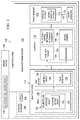
- image processing system 100 may include object detector 114, classifier 115, and target manager 116.
- object detector 114, classifier 115, and target manager 116 may be implemented using hardware, firmware, software, or a combination thereof.
- Object detector 114 may receive sequence of images 104 from imaging system 108.
- Image 118 may be an example of one of sequence of images 104.
- Object detector 114 is configured to detect potential objects in image 118.
- a potential object may potentially be target of interest 112.
- object detector 114 may detect potential object 120 within candidate chip 122 in image 118.
- Object detector 114 may use a number of algorithms, techniques, or computational processors to detect potential object 120.
- potential object 120 may be potential moving object 124. In this manner, object detector 114 may also be referred to as a moving object detector.
- a chip may be a region of an image.
- a candidate chip such as candidate chip 122, may be a region of an image that captures a potential object.
- candidate chip 122 may be a region of image 118 that is identified as potentially capturing target of interest 112.
- object detector 114 may include first verifier 126. First verifier 126 may verify that potential object is candidate object 128 and not false detection 130. If first verifier 126 determines that potential object is false detection 130, object detector 114 then proceeds with processing the next image in sequence of images 104.
- classifier 115 may then classify candidate object 128 as one of candidate target 132 or background 134. This classification may be performed in a number of different ways. In one illustrative example, classifier 115 may use rotationally shifted histograms of oriented gradients 136 to perform this classification. Rotationally shifted histograms of oriented gradients 136 may also be referred to as rotationally shifting histograms of oriented gradients, circularly shifting histograms of oriented gradients, or circularly shifted histograms of oriented gradients.
- a target recognition method an edge detection method, a chrominance pattern comparison method, a shape comparison method, a linearly constrained minimum variance (LCMV) method, a correlation matrix method, or some other type of method may be used.
- LCMV linearly constrained minimum variance
- the phrase "at least one of,” when used with a list of items, means different combinations of one or more of the listed items may be used and only one of the items in the list may be needed.
- the item may be a particular object, thing, step, operation, process, or category.
- "at least one of” means any combination of items or number of items may be used from the list, but not all of the items in the list may be required.
- “at least one of item A, item B, or item C” or “at least one of item A, item B, and item C” may mean item A; item A and item B; item B; item A, item B, and item C; or item B and item C.
- “at least one of item A, item B, or item C” or “at least one of item A, item B, and item C” may mean, but is not limited to, two of item A, one of item B, and ten of item C; four of item B and seven of item C; or some other suitable combination.
- candidate object 128 is classified as background 134, then target of interest 112 has not been detected. However, if candidate object 128 is classified as candidate target 132, then a second verification may be performed.
- classifier 115 may include second verifier 138.
- Second verifier 138 may verify that candidate target 132 is indeed target of interest 112. If second verifier 138 is unable to successfully verify that candidate target 132 is target of interest 112, then candidate target 132 is designated as background 134.
- target manager 116 may be used to generate target signature 140 for target of interest 112 based on candidate chip 122.
- Target signature 140 includes information that may be used to track target of interest 112 in a set of subsequent images in sequence of images 104.
- Target signature 140 may include, for example, without limitation, a fingerprint vector and covariance matrix for target of interest 112, computed with respect to candidate chip 122.
- the fingerprint vector may be generated, for example, without limitation, with respect to a color space, such as, but not limited to, a chroma-based color space.
- the fingerprint vector may provide chromaticity information.
- the chromaticity information may include, for example, without limitation, a luminance mean value, a red chrominance mean value, a blue chrominance mean value, luminance entropy, red chrominance entropy, and blue chrominance entropy.
- target signature 140 for target of interest 112 may also include shape information, location information, orientation information, or some combination thereof for use in tracking target of interest 112.
- object detector 114 may also identify current object information 200 for potential object 120.
- Current object information 200 may include at least one of appearance 202, direction of movement 204, or some other type of information.
- direction of movement 204 may comprise an orientation of potential object 120 with respect to a reference coordinate system. This reference coordinate system may be used for sequence of images 104. In some cases, direction of movement 204 may also comprise a position of potential object 120 with respect to the reference coordinate system.
- Object detector 114 identifies appearance 202 of potential object 200 using at least one of size 206, color pattern 208, shape information 210, or some other type of information about potential object 120.
- Size 206 may be, for example, without limitation, based on the number of pixels in image 118 that represent potential object 120, a number of dimensions for potential object 120, or some other measure of size.
- Color pattern 208 may provide information about the pixel values of pixels detected as representing potential object 120 with respect to one or more selected color spaces.
- color pattern 208 takes the form of chrominance pattern 212, which corresponds to a chroma-based color space.
- Shape information 210 may include, for example, without limitation, at least one of information about the overall shape of potential object 120, information about the edges of potential object 120, or some other type of information.
- First verifier 126 uses current object information 200 to verify that potential object 120 is candidate object 128. In one illustrative example, first verifier 126 determines whether potential object 120 matches a previously detected potential object in at least one previous image of sequence of images 104 that was processed by object detector 114 based on current object information 200.
- past information 214 about number of previously detected potential objects 215 may be stored in data structure 216.
- data structure 216 may comprise one or more databases.
- a "number of" items may include one or more items.
- number of previously detected potential objects 215 may include one or more previously detected potential objects.
- no previously detected potential objects may exist.
- Number of unique identifiers 217 and number of consistency indices 218 may be stored in data structure 216. Each of number of unique identifiers 217 may correspond to one of number of previously detected potential objects 215 that is being tracked through one or more images of sequence of images 104 in Figure 1 .
- Past information 214 may include past object information associated with each of number of unique identifiers 217.
- a consistency index in number of consistency indices 218 may be, for example, without limitation, a counting index.
- a consistency index may be a count of the number of times that a previously detected potential object has been detected in the previously processed images of sequence of images 104.
- unique identifier 220 may correspond to previously detected potential object 221 in number of previously detected potential objects 215.
- Past object information 222 may be the information previously generated by object detector 114 for previously detected potential object 221.
- First verifier 126 may compare current object information 200 to past object information 222.
- first verifier 126 may then update consistency index 223 corresponding to previously detected potential object 221. For example, without limitation, first verifier 126 may increase consistency index 223 by one.
- First verifier 126 may then determine whether consistency index 223 has reached selected threshold value 224.
- Selected threshold value 224 may be selected to ensure consistency in the detection of potential objects by object detector 114. Depending on the implementation, selected threshold value 224 may be two, three, five, ten, twenty, or some other value.
- first verifier 126 has not reached selected threshold value 224, then potential object 120 is not yet considered candidate object 128.
- Object detector 114 may then process a next image in sequence of images 104. However, if first verifier 126 has reached selected threshold value 224, then first verifier 126 designates potential object 120 as candidate object 128.
- Candidate object 128 may keep unique identifier 220.
- first verifier 126 may compare current object information 200 to the past object information for each previously detected potential object to identify the best matched previously detected potential object. If current object information 200 matches the past object information for this best matched previously detected potential object within selected tolerances, first verifier 126 may then update consistency index for the corresponding best matched previously detected potential object.
- first verifier 126 determines that current object information 200 does not match the past object information associated with any of number of unique identifiers 217 for number of previously detected potential objects 215, first verifier 126 assigns new unique identifier 226 to potential object 120. First verifier 126 then stores new unique identifier 226 along with current object information 200 for potential object 120 in data structure 216 for later use.
- object detector 114 may store candidate chip 122 in data structure 216 in association with the corresponding unique identifier for future use. If candidate object 128 is later determined to be target of interest 112 by classifier 115, as described in Figure 1 , candidate chip 122 may then be referred to as a target chip.
- classifier 115 may then classify candidate object 128.
- Classifier 115 classifies candidate object 128 as candidate target 132 or background 134. This classification may be performed in different ways using different types of classification techniques and algorithms.
- classifier 115 may use rotationally shifted histograms of oriented gradients 136.
- classifier 115 may divide candidate chip 122 into grid of cells 300.
- Grid of cells 300 may be a grid of multiple rows and multiple columns.
- Classifier 115 may then use number of sub-region masks 302 to identify plurality of sub-regions 304.
- Each of number of sub-region masks 302 may have different dimensions.
- number of sub-region masks 302 may include sub-region mask 305 having selected dimensions 306.
- Selected dimensions 306 may include, for example, without limitation, a row dimension and a column dimension. Selected dimensions 306 may be selected such that sub-region mask 305 is smaller than candidate chip 122. For example, without limitation, if grid of cells 300 for candidate chip 122 is a 5 by 5 grid, then sub-region mask 305 may have selected dimensions 306 of 3 by 3 or 4 by 4.
- Classifier 115 may compute plurality of scores 308 for plurality of sub-regions 304.
- classifier 115 may use rotationally shifted histograms of oriented gradients 136 and number of reference target chips 310 stored in data structure 216 in Figure 2 to compute a score for each of plurality of sub-regions 304.
- a reference target chip in number of reference target chips 310 may be an image or a portion of that image that is known to capture target of interest 112 in Figure 1 . This image may be independent of sequence of images 104 in Figure 1 .
- the reference target chip may be a stock picture of a ground vehicle of interest.
- a reference target chip in number of reference target chips 310 may take the form of a region of a previous image in sequence of images 104 within which a potential object was detected, verified as a candidate object, classified as a candidate target, and then verified as target of interest 112.
- Sub-region 312 may be an example of one of plurality of sub-regions 304.
- Sub-region 312 may include plurality of cells 313.
- Classifier 115 generates score 314 for sub-region 312 based on sub-region 312 and number of reference target chips 310 stored in data structure 216.
- classifier 115 identifies base histogram vector 316 for sub-region 312.
- Base histogram vector 316 may be computed using the method of computing histograms of oriented gradients (HoG).
- base histogram vector 316 is a feature descriptor. This feature descriptor may be generated by computing a histogram of oriented gradients for each cell in plurality of cells 313 of sub-region 312 and discretizing the histogram for each cell into bins to ultimately form a vector of cells in which each cell comprises a vector of bins.
- Base histogram vector 316 may capture shape information 318 for candidate object 128 within sub-region 312 by capturing information about the gradients. Each bin within the vector of bins for a particular cell of plurality of cells 313 captures the proportional contribution of each pixel in that cell to the gradient magnitude at that pixel.
- base histogram vector 316 may include plurality of cell vectors 320.
- base histogram vector 316 may include M cells, each of which corresponds to one of plurality of cells 313 of sub-region 312. Each of the M cells may have N rotational steps. In this manner, each of the M cells may be considered a cell vector.
- Number of rotational shifts 322 may be applied to plurality of cells 313 in sub-region 312 to generate rotationally shifted versions of base histogram vector 316. Together, these rotationally shifted histogram vectors and base histogram vector 316 form plurality of histogram vectors 324.
- sub-region 312 comprises 9 cells that form a 3 by 3 grid
- sub-region 312 may be rotated 8 times.
- sub-region 312 comprises 16 cells that form a 4 by 4 grid
- sub-region 312 may be rotated 12 times.
- plurality of histogram vectors 324 may be formed by rotationally shifted histograms of oriented gradients 136.
- Classifier 115 may then compare each of plurality of histogram vectors 324 to reference histogram vector 326 for selected reference target chip 327 in number of reference target chips 310 to generate plurality of matching scores 328.
- matching score 330 in plurality of matching scores 328 may be a measure of the likeness or a degree of matching between reference histogram vector 326 and a corresponding histogram vector of plurality of histogram vectors 324.
- classifier 115 may select best matching score 332 from plurality of matching scores 328.
- the best matching score may be the minimum score of plurality of matching scores 328.
- the process of generating best matching score 332 for sub-region 312 may be repeated using the corresponding reference histogram vector for each of number of reference target chips 310 to form number of best matching scores 334 for sub-region 312.
- the best score of number of best matching scores 334 may be assigned as score 314 for sub-region 312.
- the best score may be the minimum score of number of best matching scores 334.
- the process of generating score 314 for sub-region 312 may be repeated for each of plurality of sub-regions 304 to generate plurality of scores 308 for plurality of sub-regions 304.
- Each sub-region of plurality of sub-regions 304 may then be classified as either "target” or "background” based on the corresponding score of that sub-region.
- sub-region 312 may be classified as "target” when score 314 for sub-region 312 meets a selected requirement and may be classified as "background” when score 314 does not meet the selected requirement.
- the selected requirement may be, for example, that score 314 be below a maximum threshold.
- the selected requirement may be that score 314 be above a minimum threshold.
- plurality of classifications 336 may be generated for plurality of sub-regions 304.
- Plurality of classifications 336 may then be used to generate final classification 338 for candidate object 128. For example, without limitation, if at least one of plurality of classifications 336 is "target,” then final classification 338 for candidate object 128 may be candidate target 132. However, if none of plurality of classifications 336 is "target,” then final classification 338 for candidate object 128 may be background 134. In other words, classifier 115 may classify candidate object 128 as candidate target 132 when at least one of plurality of scores 308 meets the selected requirement, but may classify candidate object 128 as background 134 if none of plurality of scores 308 meets the selected requirement.
- Second verifier 138 may then be used to verify that candidate target 132 is indeed target of interest 112 using plurality of classifications 336.
- the overall verification process used by second verifier 138 may be based on the K -nearest-neighbors technique.
- target class 340 Any and all sub-regions in plurality of sub-regions 304 having a classification of "target” may be designated as forming target class 340. Any and all sub-regions in plurality of sub-regions 304 having a classification of "background” may be designated as forming background class 342. In some cases, either target class 340 or background class 342 may be an empty class.
- second verifier 138 may automatically verify that candidate target 132 is indeed target of interest 112. However, if both background class 342 and target class 340 each include one or more class members, second verifier 138 may need to perform further steps.
- second verifier 138 computes first parameter 344 for plurality of sub-regions 304 and second parameter 346 for plurality of sub-regions 304.
- First parameter 344 may be related to target class 340.
- first parameter 344 and second parameter 346 may be the size of target class 340 and background class 342, respectively.
- a size of a class may be the number of class members in that class.
- Second verifier 138 then computes ratio 348 of first parameter 344 to second parameter 346. Second verifier 138 may determine whether ratio 348 is at least selected weighted ratio 350. In other words, second verifier 138 determines whether ratio 348 is equal to or greater than selected weighted ratio 350. Selected weighted ratio 350 may be selected to improve the accuracy of detecting target of interest 112 and reduce the number of false detections of target of interest 112.
- Selected weighted ratio 350 may be weighted because this weighting provides an improved capability of correcting a wrong background detection to a correct target detection than correcting a wrong target detection to a correct background detection. This improved capability may be needed more for correcting a wrong background detection to a correct target detection because a candidate chip that contains background, but that is mistakenly classified as containing target of interest 112, may be later disregarded in subsequent processing of images by object detector 114 described in Figures 1-2 .
- selected weighted ratio 350 may be set based on a training process using reference target chips and reference background chips. In another illustrative example, selected weighted ratio 350 may be set to be between about two-thirds and one such that more weight may be applied to detect targets. For example, if ratio 348 is equal to or greater than selected weighted ratio 350, second verifier 138 successfully verifies that candidate target 132 is indeed target of interest 112.
- second verifier 138 may then compute new ratio 354 because the difference in the sizes of the two classes may not be sufficiently distinguishing.
- New ratio 354 may be a ratio of new first parameter 354 to second new parameter 356.
- new first parameter 354 may be a mean of the one or more scores corresponding to the sub-regions that fall within target class 340.
- new second parameter 356 may be the mean of the one or more scores corresponding to the sub-regions that fall within background class 342.
- Second verifier 138 compares new ratio 352 to differentiation factor 358. Differentiation factor 358 is used to ensure that there is sufficient differentiation between the scores of the sub-regions that fall in target class 340 and the scores of the sub-regions that fall in background class 342.
- Differentiation factor 358 may also be weighted such that more weight may be applied to detect targets. If new ratio 352 is equal to or less than differentiation factor 358, second verifier 138 successfully verifies that candidate target 132 is target of interest 112. However, if new ratio 352 is greater than differentiation factor 358, second verifier 138 may remove candidate target 132 from consideration as target of interest 112 and may reclassify candidate target 132 as background 134.
- the first verification process formed by object detector 114 and the second verification process formed by classifier 115 may form a double verification process that improves the accuracy of target detection. In this manner, the accuracy of target tracking may also be improved.
- image processing system 100 in Figure 1 object detector 114 in Figures 1-2 , and classifier 115 in Figures 1 and 3 are not meant to imply physical or architectural limitations to the manner in which an illustrative embodiment may be implemented.
- Other components in addition to or in place of the ones illustrated may be used. Some components may be optional.
- the blocks are presented to illustrate some functional components. One or more of these blocks may be combined, divided, or combined and divided into different blocks when implemented in an illustrative embodiment.
- image 400 is an example of one implementation for image 118 in Figure 1 .
- Image 400 may take the form of electro-optical image 401 in this illustrative example.
- Image 400 captures background 402, potential object 406, potential object 408, and potential object 410.
- potential object 406, potential object 408, and potential object 410 are detected within candidate chip 412, candidate chip 413, and candidate chip 414, respectively.
- Each of potential object 406, potential object 408, and potential object 410 may be an example of one implementation for potential object 120 described in Figures 1-2 .
- each of candidate chip 412, candidate chip 413, and candidate chip 414 may be an example of one implementation for candidate chip 122 described in Figures 1-2 .
- candidate chip 414 may be divided into grid 500 comprising cells 502.
- Grid 500 may be a 5 by 5 grid in this illustrative example.
- cells 502 include 25 cells in this example.
- sub-region mask 600 has been positioned over a portion of candidate chip 414 to identify sub-region 602.
- Sub-region mask 600 may be an example of one implementation for sub-region mask 305 in Figure 3 . As depicted, sub-region mask 600 may be a 3 by 3 grid, comprising 9 cells. Sub-region mask 600 may be moved to a different location over candidate chip 414 to identify another sub-region, such as sub-region 604.
- Sub-region mask 600 may be moved to other locations to identify other sub-regions within candidate chip 414. Based on the size of sub-region mask 600, a portion of each of the sub-regions identified for candidate chip 414 may overlap with some portion of at least one other sub-region.
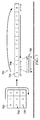
- FIG. 7 an illustration of sub-region 602 from Figure 6 is depicted in accordance with an illustrative embodiment.
- cells 700 have been assigned corresponding index numbers 701.
- Base histogram vector 702 may be generated for sub-region 602.
- Base histogram vector 702 may be an example of one implementation for base histogram vector 316 in Figure 3 . As depicted, base histogram vector 702 may comprise plurality of cell vectors 704.
- Cell vector 706 may be an example of one of plurality of cell vectors 704.
- Cell vector 706 may include plurality of bins 708.
- Plurality of bins 708 may represent a histogram of oriented gradients that has been discretized.
- FIG. 8 an illustration of a process for performing target detection is depicted in the form of a flowchart in accordance with an illustrative embodiment.
- the process illustrated in Figure 8 may be implemented using image processing system 100 and the different components of image processing system 100 described in Figures 1-3 .
- the process may begin by detecting a potential object within a candidate chip in an image (operation 800). Next, the process may verify that the potential object is a candidate object (operation 802).
- the candidate object may be classified as one of a candidate target or a background in response to the potential object being verified as the candidate object (operation 804).
- the process may verify that the candidate target is a target of interest in response to the candidate object being classified as the candidate target (operation 806), with the process terminating thereafter.
- FIG. 9 an illustration of a process for performing target detection is depicted in the form of a flowchart in accordance with an illustrative embodiment.
- the process illustrated in Figure 9 may be implemented using image processing system 100 and the different components of image processing system 100 described in Figures 1-3 .
- the process may begin by receiving a sequence of images (operation 900).
- An image in the sequence of images may be selected for processing (operation 902).
- the first time that operation 902 is performed, the image selected may be the initial image of the sequence of images with respect to time.
- the image may be processed to determine whether any potential moving objects are detected in the image (operation 904). If no potential moving objects are detected in the image, a determination may be made as to whether any further images are present in the sequence of images (operation 906). If no further images are present, the process terminates. Otherwise, the process returns to operation 902, as described above, such that a next image in the sequence of images is selected for processing.
- a candidate chip is extracted from the image for each potential moving object (operation 908).
- a candidate chip capturing a potential moving object is then selected for processing (operation 910).
- a determination may be made as to whether the potential moving object is a candidate object based on a first verification process (operation 912). If the potential moving object is not a candidate object, the process makes a determination as to whether any unprocessed candidate chips remain (operation 914). If no unprocessed candidate chips remain, the process proceeds to operation 906 as described above. Otherwise, the process returns to operation 910 described above.
- the candidate object is classified as one of a candidate target or a background (operation 916).
- a determination may then be made as to whether the candidate target is indeed a target of interest based on a second verification process (operation 918).
- the process returns to operation 910 described above. However, if the candidate target is indeed a target of interest, the candidate chip for the target of interest is stored in a data structure as a target chip (operation 920). Thereafter, a target signature is generated for the target of interest and stored in the data structure (operation 922), with the process then returning to operation 912 described above.
- FIG. 10 an illustration of a process for detecting a potential object and verifying the potential object as a candidate object is depicted in the form of a flowchart in accordance with an illustrative embodiment.
- the process illustrated in Figure 10 may be implemented using image processing system 100 in Figure 1 .
- this process may be implemented using object detector 114 described in Figures 1-2 .
- the process may begin receiving an image (operation 1000). Next, a potential object is detected within a candidate chip in the image (operation 1002). Current object information is generated for the potential object in which the current object information includes at least one of an appearance or a direction of movement of the potential object (operation 1004).
- a consistency index associated with the new unique identifier is then initialized (operation 1010).
- the new unique identifier, the consistency index, and the current object information identified for the potential object are stored in a data structure (operation 1012), with the process then terminating.
- a consistency index associated with a unique identifier corresponding to the previously detected potential object is updated (operation 1014).
- the consistency index is increased by one in operation 1014.
- This process may be repeated for each image in a sequence of images that is received. Further, the process of verifying the potential object may be repeated for each potential object detected in each image.
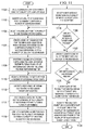
- FIG. 11 an illustration of a process for classifying a candidate object as a candidate target or a background is depicted in the form of a flowchart in accordance with an illustrative embodiment.
- the process illustrated in Figure 11 may be implemented using image processing system 100 in Figure 1 .
- this process may be implemented using classifier 115 described in Figures 1 and 3 .
- the process may begin by dividing a candidate chip containing a candidate object into a grid of cells (operation 1100). A plurality of sub-regions may be identified for the candidate chip using a number of sub-region masks (operation 1102). A sub-region may then be selected from the plurality of sub-regions for processing (operation 1104).
- a base histogram vector is created for the sub-region selected in which the base histogram vector comprises a plurality of cell vectors corresponding to a plurality of cells in the sub-region (operation 1106).
- a number of rotational shifts are performed using the base histogram vector to form a plurality of histogram vectors that includes the base histogram vector (operation 1108).
- a reference target chip is selected from a number of reference target chips (operation 1110).
- a reference histogram vector is identified for the reference target chip selected (operation 1112).
- the reference histogram vector may be paired with each of the plurality of histogram vectors to form a plurality of pairings (operation 1114).
- a matching score may be computed for each pairing of the plurality of pairings to form a plurality of matching scores for the sub-region (operation 1116).
- a best matching score may be selected from the plurality of matching scores for the sub-region (operation 1118).
- the best matching score selected may be an overall score for the pairing of the sub-region and the reference target chip selected.
- the best matching score may be the minimum value for each r th rotation.
- the candidate object is classified as a candidate target if at least one of the plurality of sub-regions is classified as a "target” and as background if none of the plurality of sub-regions is classified as a "target” (operation 1128), with the process terminating thereafter. All sub-regions classified as "target” belong to a target class. All sub-regions classified as "background” belong to a background class.
- FIG 12 an illustration of a process for verifying that a candidate target is indeed a target of interest is depicted in the form of a flowchart in accordance with an illustrative embodiment.
- the process illustrated in Figure 11 may be implemented using image processing system 100 in Figure 1 .
- this process may be implemented using classifier 115 described in Figures 1 and 3 .
- the process may begin by identifying a selected weighted ratio for performing a verification of a candidate target (operation 1200). Next, a first parameter is computed based on a number of sub-regions belonging to a target class (operation 1202). A second parameter is computed based on the number of sub-regions belonging to a background class (operation 1204).
- a new ratio is computed using a new first parameter and a new second parameter (operation 1210).
- the new first parameter may be a mean of the scores of the number of sub-regions belonging to the target class
- the new second parameter may be a mean of the scores of the number of sub-regions belonging to the background class.
- a differentiation factor is identified (operation 1212).
- a determination may be made as to whether the new ratio is less than the differentiation factor (operation 1214). If the new ratio is less than the differentiation factor, the process proceeds to operation 1208 described above. Otherwise, the candidate target is removed from consideration as the target of interest and reclassified as a background (operation 1216), with the process terminating thereafter.
- FIG. 13 an illustration of a process for identifying a differentiation factor for performing a verification of a candidate target is depicted in the form of a flowchart in accordance with an illustrative embodiment.
- the process illustrated in Figure 13 may be implemented using image processing system 100 in Figure 1 .
- this process may be implemented using classifier 115 described in Figures 1 and 3 .
- the process may begin by identifying a plurality of reference target chips and a plurality of reference background chips (operation 1300).
- a score is generated for each unique pairing of one of the plurality of reference target chips with another one of the plurality of reference target chips to form a plurality of first scores (operation 1302).
- a mean of the plurality of first scores is computed to form a first mean score (operation 1304).
- a standard deviation for the plurality of first scores is computed (operation 1306).
- a score is generated for each unique pairing of one of the plurality of reference target chips with one of the plurality of reference background chips to form a plurality of second scores (operation 1308).
- a mean of the plurality of second scores is computed to form a second mean score (operation 1310).
- a differentiation factor is computed using the first mean score, the second mean score, and the standard deviation (operation 1312), with the process terminating thereafter.
- each block in the flowcharts or block diagrams may represent a module, a segment, a function, and/or a portion of an operation or step.
- the function or functions noted in the blocks may occur out of the order noted in the figures.
- two blocks shown in succession may be executed substantially concurrently, or the blocks may sometimes be performed in the reverse order, depending upon the functionality involved.
- other blocks may be added in addition to the illustrated blocks in a flowchart or block diagram.
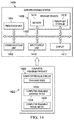
- Data processing system 1400 may be used to implement computer system 102 in Figure 1 .
- data processing system 1400 includes communications framework 1402, which provides communications between processor unit 1404, storage devices 1406, communications unit 1408, input/output unit 1410, and display 1412.
- communications framework 1402 may be implemented as a bus system.
- Processor unit 1404 is configured to execute instructions for software to perform a number of operations.
- Processor unit 1404 may comprise a number of processors, a multiprocessor core, and/or some other type of processor, depending on the implementation.
- processor unit 1404 may take the form of a hardware unit, such as a circuit system, an application specific integrated circuit (ASIC), a programmable logic device, or some other suitable type of hardware unit.
- ASIC application specific integrated circuit
- Storage devices 1406 may be in communication with processor unit 1404 through communications framework 1402.
- a storage device also referred to as a computer readable storage device, is any piece of hardware capable of storing information on a temporary and/or permanent basis. This information may include, but is not limited to, data, program code, and/or other information.
- Memory 1414 and persistent storage 1416 are examples of storage devices 1406.
- Memory 1414 may take the form of, for example, a random access memory or some type of volatile or non-volatile storage device.
- Persistent storage 1416 may comprise any number of components or devices.
- persistent storage 1416 may comprise a hard drive, a flash memory, a rewritable optical disk, a rewritable magnetic tape, or some combination of the above.
- the media used by persistent storage 1416 may or may not be removable.
- Communications unit 1408 allows data processing system 1400 to communicate with other data processing systems and/or devices. Communications unit 1408 may provide communications using physical and/or wireless communications links.
- Input/output unit 1410 allows input to be received from and output to be sent to other devices connected to data processing system 1400.
- input/output unit 1410 may allow user input to be received through a keyboard, a mouse, and/or some other type of input device.
- input/output unit 1410 may allow output to be sent to a printer connected to data processing system 1400.
- Display 1412 is configured to display information to a user.
- Display 1412 may comprise, for example, without limitation, a monitor, a touch screen, a laser display, a holographic display, a virtual display device, and/or some other type of display device.
- processor unit 1404 may perform the processes of the different illustrative embodiments using computer-implemented instructions. These instructions may be referred to as program code, computer usable program code, or computer readable program code and may be read and executed by one or more processors in processor unit 1404.
- program code 1418 is located in a functional form on computer readable media 1420, which is selectively removable, and may be loaded onto or transferred to data processing system 1400 for execution by processor unit 1404.
- Program code 1418 and computer readable media 1420 together form computer program product 1422.
- computer readable media 1420 may be computer readable storage media 1424 or computer readable signal media 1426.
- Computer readable storage media 1424 is a physical or tangible storage device used to store program code 1418 rather than a medium that propagates or transmits program code 1418.
- Computer readable storage media 1424 may be, for example, without limitation, an optical or magnetic disk or a persistent storage device that is connected to data processing system 1400.
- program code 1418 may be transferred to data processing system 1400 using computer readable signal media 1426.
- Computer readable signal media 1426 may be, for example, a propagated data signal containing program code 1418. This data signal may be an electromagnetic signal, an optical signal, and/or some other type of signal that can be transmitted over physical and/or wireless communications links.
- data processing system 1400 in Figure 14 is not meant to provide architectural limitations to the manner in which the illustrative embodiments may be implemented.
- the different illustrative embodiments may be implemented in a data processing system that includes components in addition to or in place of those illustrated for data processing system 1400. Further, components shown in Figure 14 may be varied from the illustrative examples shown.
Landscapes
- Engineering & Computer Science (AREA)
- Theoretical Computer Science (AREA)
- General Physics & Mathematics (AREA)
- Physics & Mathematics (AREA)
- Multimedia (AREA)
- Computer Vision & Pattern Recognition (AREA)
- Data Mining & Analysis (AREA)
- Evolutionary Computation (AREA)
- Artificial Intelligence (AREA)
- General Engineering & Computer Science (AREA)
- Life Sciences & Earth Sciences (AREA)
- Evolutionary Biology (AREA)
- Bioinformatics & Computational Biology (AREA)
- Bioinformatics & Cheminformatics (AREA)
- Health & Medical Sciences (AREA)
- Computing Systems (AREA)
- Databases & Information Systems (AREA)
- General Health & Medical Sciences (AREA)
- Medical Informatics (AREA)
- Software Systems (AREA)
- Image Analysis (AREA)
Abstract
Description
- The present disclosure relates generally to processing images and, in particular, to processing images to detect targets of interest. Still more particularly, the present disclosure relates to a method and apparatus for detecting a target of interest using a double verification process.
- Sensor devices are oftentimes used to generate sensor data for the purpose of detecting targets of interest. Different types of sensor devices may be used to perform target detection. For example, without limitation, electro-optical (EO) sensors, infrared (IR) imaging systems, radar imaging systems, and other types of sensor devices may be used to perform target detection.
- Target detection may be performed in a number of different ways. As one example, an unmanned aerial vehicle (UAV) may be used to surveil an area and detect any targets of interest that are on ground. The target of interest may be, for example, but is not limited to, a ground vehicle, a person, or some other type of target.
- Some currently available methods for performing target detection are unable to detect targets with a desired level of accuracy. For example, when targets of interest are located in environments that are crowded, such as urban environments, distinguishing between the targets of interest and a background in images may be more difficult than desired. Further, some currently available methods for performing target detection in images may be unable to detect targets that are at least partially occluded with the desired level of accuracy and efficacy. Therefore, it would be desirable to have a method and apparatus that take into account at least some of the issues discussed above, as well as other possible issues.
- In one illustrative embodiment, a method for performing target detection is provided. A potential object is detected within a candidate chip in an image. The potential object is verified as a candidate object. The candidate object is classified as one of a candidate target or a background in response to the potential object being verified as the candidate object. The candidate target is verified as a target of interest in response to the candidate object being classified as the candidate target.
- In another illustrative embodiment, a method for processing images is provided. A potential moving object is detected within a candidate chip in an image. The potential moving object is verified as a candidate object based on at least one of an appearance of the potential moving object or a direction of movement of the potential moving object. The candidate object is classified as one of a candidate target or a background in response to the potential moving object being verified as the candidate object. The candidate target is verified as a target of interest in response to the candidate object being classified as the candidate target using a number of reference target chips.
- In yet another illustrative embodiment, an apparatus comprises an object detector and a classifier. The object detector detects a potential object within a candidate chip in an image. The object detector further verifies that the potential object is a candidate object. The classifier classifies the candidate object as one of a candidate target or a background in response to the potential object being verified as the candidate object. The classifier further verifies that the candidate target is a target of interest in response to the candidate object being classified as the candidate target.
- The features and functions can be achieved independently in various embodiments of the present disclosure or may be combined in yet other embodiments in which further details can be seen with reference to the following description and drawings.
- The novel features believed characteristic of the illustrative embodiments are set forth in the appended claims. The illustrative embodiments, however, as well as a preferred mode of use, further objectives and features thereof, will best be understood by reference to the following detailed description of an illustrative embodiment of the present disclosure when read in conjunction with the accompanying drawings, wherein:
-
Figure 1 is an illustration of an image processing system in the form of a block diagram in accordance with an illustrative embodiment; -
Figure 2 is an illustration of an object detector in greater detail in the form of a block diagram in accordance with an illustrative embodiment; -
Figure 3 is an illustration of a classifier in greater detail in the form of a block diagram in accordance with an illustrative embodiment; -
Figure 4 is an illustration of potential objects that have been detected in an image in accordance with an illustrative embodiment; -
Figure 5 is an illustration of one manner of dividing a candidate chip into a grid of cells in accordance with an illustrative embodiment; -
Figure 6 is an illustration of different sub-regions in a candidate chip in accordance with an illustrative embodiment; -
Figure 7 is an illustration of a sub-region in accordance with an illustrative embodiment; -
Figure 8 is an illustration of a process for performing target detection in the form of a flowchart in accordance with an illustrative embodiment; -
Figure 9 is an illustration of a process for performing target detection in the form of a flowchart in accordance with an illustrative embodiment; -
Figure 10 is an illustration of a process for detecting a potential object and verifying the potential object as a candidate object in the form of a flowchart in accordance with an illustrative embodiment; -
Figure 11 is an illustration of a process for classifying a candidate object as a candidate target or a background in the form of a flowchart in accordance with an illustrative embodiment; -
Figure 12 is an illustration of a process for verifying that a candidate target is indeed a target of interest in the form of a flowchart in accordance with an illustrative embodiment; -
Figure 13 is an illustration of a process for identifying a differentiation factor for performing a verification of a candidate target in the form of a flowchart in accordance with an illustrative embodiment; and -
Figure 14 is an illustration of a data processing system in the form of a block diagram in accordance with an illustrative embodiment. - The illustrative embodiments recognize and take into account different considerations. For example, the illustrative embodiments recognize and take into account that it may be desirable to provide a method for detecting targets of interest with a desired level of accuracy. In particular, the illustrative embodiments recognize and take into account that it may be desirable to provide a method for detecting targets of interest in images with the desired level of accuracy even against busy environments and when the targets are partially occluded.
- Thus, the illustrative embodiments provide a method for processing images to perform target detection and recognition. As one illustrative example, a potential object may be detected within a candidate chip in an image. The potential object is then verified as a candidate object. If the potential object does not pass this first verification, the potential object may be considered a false detection. The candidate object may be classified as one of a candidate target or a background in response to the potential object being successfully verified as the candidate object. The candidate target may then be verified as a target that is of interest in response to the candidate object being classified as the candidate target. This second verification may ensure that the classification of the candidate target has a desired level of accuracy and that the candidate target is not a background that has been misclassified.
- In this manner, the illustrative embodiments provide a method for detecting targets that may be used in a number of different applications. For example, without limitation, this process may be easily and quickly performed for use in automatic ground vehicle detection from unmanned aerial vehicles. Further, this process may enable more accurate and efficient persistent target tracking and target reacquisition from unmanned aerial vehicles.
- Referring now to the figures and, in particular, with reference to
Figure 1 , an illustration of an image processing system is depicted in the form of a block diagram in accordance with an illustrative embodiment. In this illustrative example,image processing system 100 may be implemented using software, hardware, firmware, or a combination thereof. - When software is used, the operations performed by
image processing system 100 may be implemented using, for example, without limitation, program code configured to run on a processor unit. When firmware is used, the operations performed byimage processing system 100 may be implemented using, for example, without limitation, program code and data and stored in persistent memory to run on a processor unit. - When hardware is employed, the hardware may include one or more circuits that operate to perform the operations performed by
image processing system 100. Depending on the implementation, the hardware may take the form of a circuit system, an integrated circuit, an application specific integrated circuit (ASIC), a programmable logic device, or some other suitable type of hardware device configured to perform any number of operations. - A programmable logic device may be configured to perform certain operations. The device may be permanently configured to perform these operations or may be reconfigurable. A programmable logic device may take the form of, for example, without limitation, a programmable logic array, a programmable array logic, a field programmable logic array, a field programmable gate array, or some other type of programmable hardware device.
- In one illustrative example,
image processing system 100 may be implemented incomputer system 102.Image processing system 100 may be used to process sequence ofimages 104. Sequence ofimages 104 may be a plurality of images ordered with respect to time. Each image in each sequence of images may be a still image. In some cases, sequence ofimages 104 may be referred to asvideo 106. In these cases, each image invideo 106 may be referred to as a frame. -
Image processing system 100 may receive sequence ofimages 104 fromimaging system 108.Imaging system 108 may take the form of, for example, without limitation, electro-optical (EO)imaging system 110. However, in other illustrative examples,imaging system 110 may take the form of an infrared (IR) imaging system, a radar imaging system, or some other type of imaging system. -
Image processing system 100 may process sequence ofimages 104 to detect target ofinterest 112. Target ofinterest 112 may be, for example, without limitation, moving target ofinterest 113. In some cases, target ofinterest 112 may be identified prior to the beginning of processing sequence ofimages 104. In other cases, target ofinterest 112 may be acquired during processing of sequence ofimages 104. - Target of
interest 112 may take a number of different forms. For example, without limitation, target ofinterest 112 may be a person, a type of ground vehicle, a type of aerial vehicle, a water vehicle, or some other type of object. The ground vehicle may be, for example, without limitation, a car, a truck, a tank, or some other type of ground vehicle. The aerial vehicle may be a missile, an aircraft, an unmanned aerial vehicle, or some other type of aerial vehicle. In some cases, target ofinterest 112 may be a specified target. - As depicted,
image processing system 100 may includeobject detector 114,classifier 115, andtarget manager 116. Each ofobject detector 114,classifier 115, andtarget manager 116 may be implemented using hardware, firmware, software, or a combination thereof. -
Object detector 114 may receive sequence ofimages 104 fromimaging system 108.Image 118 may be an example of one of sequence ofimages 104.Object detector 114 is configured to detect potential objects inimage 118. A potential object may potentially be target ofinterest 112. - For example, without limitation,
object detector 114 may detectpotential object 120 withincandidate chip 122 inimage 118.Object detector 114 may use a number of algorithms, techniques, or computational processors to detectpotential object 120. In one illustrative example, when target ofinterest 112 is moving target ofinterest 113,potential object 120 may be potential movingobject 124. In this manner, objectdetector 114 may also be referred to as a moving object detector. - As used herein, a chip may be a region of an image. In this manner, a candidate chip, such as
candidate chip 122, may be a region of an image that captures a potential object. In other words,candidate chip 122 may be a region ofimage 118 that is identified as potentially capturing target ofinterest 112. - Once
potential object 120 has been detected, this detection is verified. For example, without limitation,object detector 114 may includefirst verifier 126.First verifier 126 may verify that potential object iscandidate object 128 and notfalse detection 130. Iffirst verifier 126 determines that potential object isfalse detection 130,object detector 114 then proceeds with processing the next image in sequence ofimages 104. - If
first verifier 126 successfully verifies that potential object iscandidate object 128,classifier 115 may then classifycandidate object 128 as one ofcandidate target 132 orbackground 134. This classification may be performed in a number of different ways. In one illustrative example,classifier 115 may use rotationally shifted histograms of orientedgradients 136 to perform this classification. Rotationally shifted histograms of orientedgradients 136 may also be referred to as rotationally shifting histograms of oriented gradients, circularly shifting histograms of oriented gradients, or circularly shifted histograms of oriented gradients. - Of course, in other illustrative examples, other types of classification methods may be used. For example, at least one of a target recognition method, an edge detection method, a chrominance pattern comparison method, a shape comparison method, a linearly constrained minimum variance (LCMV) method, a correlation matrix method, or some other type of method may be used.
- As used herein, the phrase "at least one of," when used with a list of items, means different combinations of one or more of the listed items may be used and only one of the items in the list may be needed. The item may be a particular object, thing, step, operation, process, or category. In other words, "at least one of" means any combination of items or number of items may be used from the list, but not all of the items in the list may be required.
- For example, without limitation, "at least one of item A, item B, or item C" or "at least one of item A, item B, and item C" may mean item A; item A and item B; item B; item A, item B, and item C; or item B and item C. In some cases, "at least one of item A, item B, or item C" or "at least one of item A, item B, and item C" may mean, but is not limited to, two of item A, one of item B, and ten of item C; four of item B and seven of item C; or some other suitable combination.
- If
candidate object 128 is classified asbackground 134, then target ofinterest 112 has not been detected. However, ifcandidate object 128 is classified ascandidate target 132, then a second verification may be performed. - In this illustrative example,
classifier 115 may includesecond verifier 138.Second verifier 138 may verify thatcandidate target 132 is indeed target ofinterest 112. Ifsecond verifier 138 is unable to successfully verify thatcandidate target 132 is target ofinterest 112, thencandidate target 132 is designated asbackground 134. - However, if
second verifier 138 does successfully verify thatcandidate target 132 is target ofinterest 112, thentarget manager 116 may be used to generatetarget signature 140 for target ofinterest 112 based oncandidate chip 122.Target signature 140 includes information that may be used to track target ofinterest 112 in a set of subsequent images in sequence ofimages 104. -
Target signature 140 may include, for example, without limitation, a fingerprint vector and covariance matrix for target ofinterest 112, computed with respect tocandidate chip 122. The fingerprint vector may be generated, for example, without limitation, with respect to a color space, such as, but not limited to, a chroma-based color space. - In this manner, the fingerprint vector may provide chromaticity information. The chromaticity information may include, for example, without limitation, a luminance mean value, a red chrominance mean value, a blue chrominance mean value, luminance entropy, red chrominance entropy, and blue chrominance entropy. In some cases,
target signature 140 for target ofinterest 112 may also include shape information, location information, orientation information, or some combination thereof for use in tracking target ofinterest 112. - With reference now to
Figure 2 , an illustration ofobject detector 114 fromFigure 1 is depicted in greater detail in the form of a block diagram in accordance with an illustrative embodiment. Whenobject detector 114 detectspotential object 120 withincandidate chip 122 inimage 118,object detector 114 may also identifycurrent object information 200 forpotential object 120. -
Current object information 200 may include at least one ofappearance 202, direction ofmovement 204, or some other type of information. In one illustrative example, direction ofmovement 204 may comprise an orientation ofpotential object 120 with respect to a reference coordinate system. This reference coordinate system may be used for sequence ofimages 104. In some cases, direction ofmovement 204 may also comprise a position ofpotential object 120 with respect to the reference coordinate system. -
Object detector 114 identifiesappearance 202 ofpotential object 200 using at least one ofsize 206,color pattern 208, shapeinformation 210, or some other type of information aboutpotential object 120.Size 206 may be, for example, without limitation, based on the number of pixels inimage 118 that representpotential object 120, a number of dimensions forpotential object 120, or some other measure of size. -
Color pattern 208 may provide information about the pixel values of pixels detected as representingpotential object 120 with respect to one or more selected color spaces. In one illustrative example,color pattern 208 takes the form ofchrominance pattern 212, which corresponds to a chroma-based color space.Shape information 210 may include, for example, without limitation, at least one of information about the overall shape ofpotential object 120, information about the edges ofpotential object 120, or some other type of information. -
First verifier 126 usescurrent object information 200 to verify thatpotential object 120 iscandidate object 128. In one illustrative example,first verifier 126 determines whetherpotential object 120 matches a previously detected potential object in at least one previous image of sequence ofimages 104 that was processed byobject detector 114 based oncurrent object information 200. - For example,
past information 214 about number of previously detectedpotential objects 215 may be stored indata structure 216. In one illustrative example,data structure 216 may comprise one or more databases. As used herein, a "number of" items may include one or more items. In this manner, number of previously detectedpotential objects 215 may include one or more previously detected potential objects. Of course, at the beginning of processing sequence ofimages 104 inFigure 1 , no previously detected potential objects may exist. - Number of
unique identifiers 217 and number ofconsistency indices 218 may be stored indata structure 216. Each of number ofunique identifiers 217 may correspond to one of number of previously detectedpotential objects 215 that is being tracked through one or more images of sequence ofimages 104 inFigure 1 .Past information 214 may include past object information associated with each of number ofunique identifiers 217. - Further, a consistency index in number of
consistency indices 218 may be, for example, without limitation, a counting index. In other words, a consistency index may be a count of the number of times that a previously detected potential object has been detected in the previously processed images of sequence ofimages 104. - As one illustrative example,
unique identifier 220 may correspond to previously detectedpotential object 221 in number of previously detectedpotential objects 215.Past object information 222 may be the information previously generated byobject detector 114 for previously detectedpotential object 221.First verifier 126 may comparecurrent object information 200 topast object information 222. - If
current object information 200 matchespast object information 222 within selected tolerances,first verifier 126 may then updateconsistency index 223 corresponding to previously detectedpotential object 221. For example, without limitation,first verifier 126 may increaseconsistency index 223 by one. -
First verifier 126 may then determine whetherconsistency index 223 has reached selectedthreshold value 224. Selectedthreshold value 224 may be selected to ensure consistency in the detection of potential objects byobject detector 114. Depending on the implementation, selectedthreshold value 224 may be two, three, five, ten, twenty, or some other value. - If
first verifier 126 has not reached selectedthreshold value 224, thenpotential object 120 is not yet consideredcandidate object 128.Object detector 114 may then process a next image in sequence ofimages 104. However, iffirst verifier 126 has reached selectedthreshold value 224, then first verifier 126 designatespotential object 120 ascandidate object 128.Candidate object 128 may keepunique identifier 220. - When number of previously detected
potential objects 215 includes multiple previously detected potential objects,first verifier 126 may comparecurrent object information 200 to the past object information for each previously detected potential object to identify the best matched previously detected potential object. Ifcurrent object information 200 matches the past object information for this best matched previously detected potential object within selected tolerances,first verifier 126 may then update consistency index for the corresponding best matched previously detected potential object. - In other illustrative examples, when
first verifier 126 determines thatcurrent object information 200 does not match the past object information associated with any of number ofunique identifiers 217 for number of previously detectedpotential objects 215,first verifier 126 assigns newunique identifier 226 topotential object 120.First verifier 126 then stores newunique identifier 226 along withcurrent object information 200 forpotential object 120 indata structure 216 for later use. - In some cases, once
potential object 120 has been designated ascandidate object 128,object detector 114 may storecandidate chip 122 indata structure 216 in association with the corresponding unique identifier for future use. Ifcandidate object 128 is later determined to be target ofinterest 112 byclassifier 115, as described inFigure 1 ,candidate chip 122 may then be referred to as a target chip. - With reference now to
Figure 3 , an illustration ofclassifier 115 fromFigure 1 is depicted in greater detail in the form of a block diagram in accordance with an illustrative embodiment. Oncefirst verifier 126 fromFigures 1-2 has verified thatpotential object 120 iscandidate object 128,classifier 115 may then classifycandidate object 128. -
Classifier 115 classifiescandidate object 128 ascandidate target 132 orbackground 134. This classification may be performed in different ways using different types of classification techniques and algorithms. - In one illustrative example,
classifier 115 may use rotationally shifted histograms of orientedgradients 136. For example, without limitation,classifier 115 may dividecandidate chip 122 into grid ofcells 300. Grid ofcells 300 may be a grid of multiple rows and multiple columns.Classifier 115 may then use number ofsub-region masks 302 to identify plurality ofsub-regions 304. - Each of number of
sub-region masks 302 may have different dimensions. As one illustrative example, number ofsub-region masks 302 may includesub-region mask 305 having selecteddimensions 306.Selected dimensions 306 may include, for example, without limitation, a row dimension and a column dimension.Selected dimensions 306 may be selected such thatsub-region mask 305 is smaller thancandidate chip 122. For example, without limitation, if grid ofcells 300 forcandidate chip 122 is a 5 by 5 grid, thensub-region mask 305 may have selecteddimensions 306 of 3 by 3 or 4 by 4. -
Classifier 115 may compute plurality ofscores 308 for plurality ofsub-regions 304. In particular,classifier 115 may use rotationally shifted histograms of orientedgradients 136 and number ofreference target chips 310 stored indata structure 216 inFigure 2 to compute a score for each of plurality ofsub-regions 304. - In these illustrative examples, a reference target chip in number of
reference target chips 310 may be an image or a portion of that image that is known to capture target ofinterest 112 inFigure 1 . This image may be independent of sequence ofimages 104 inFigure 1 . For example, the reference target chip may be a stock picture of a ground vehicle of interest. In other illustrative examples, a reference target chip in number ofreference target chips 310 may take the form of a region of a previous image in sequence ofimages 104 within which a potential object was detected, verified as a candidate object, classified as a candidate target, and then verified as target ofinterest 112. -
Sub-region 312 may be an example of one of plurality ofsub-regions 304.Sub-region 312 may include plurality ofcells 313.Classifier 115 generates score 314 forsub-region 312 based onsub-region 312 and number ofreference target chips 310 stored indata structure 216. - As one illustrative example,
classifier 115 identifiesbase histogram vector 316 forsub-region 312.Base histogram vector 316 may be computed using the method of computing histograms of oriented gradients (HoG). - In particular,
base histogram vector 316 is a feature descriptor. This feature descriptor may be generated by computing a histogram of oriented gradients for each cell in plurality ofcells 313 ofsub-region 312 and discretizing the histogram for each cell into bins to ultimately form a vector of cells in which each cell comprises a vector of bins.Base histogram vector 316 may captureshape information 318 forcandidate object 128 withinsub-region 312 by capturing information about the gradients. Each bin within the vector of bins for a particular cell of plurality ofcells 313 captures the proportional contribution of each pixel in that cell to the gradient magnitude at that pixel. - For example, without limitation,
base histogram vector 316 may include plurality ofcell vectors 320. As one illustrative example,base histogram vector 316 may include M cells, each of which corresponds to one of plurality ofcells 313 ofsub-region 312. Each of the M cells may have N rotational steps. In this manner, each of the M cells may be considered a cell vector. - Number of
rotational shifts 322 may be applied to plurality ofcells 313 insub-region 312 to generate rotationally shifted versions ofbase histogram vector 316. Together, these rotationally shifted histogram vectors andbase histogram vector 316 form plurality ofhistogram vectors 324. As one illustrative example, whensub-region 312 comprises 9 cells that form a 3 by 3 grid,sub-region 312 may be rotated 8 times. As another illustrative example, whensub-region 312 comprises 16 cells that form a 4 by 4 grid,sub-region 312 may be rotated 12 times. In this manner, plurality ofhistogram vectors 324 may be formed by rotationally shifted histograms of orientedgradients 136. -
Classifier 115 may then compare each of plurality ofhistogram vectors 324 toreference histogram vector 326 for selectedreference target chip 327 in number ofreference target chips 310 to generate plurality of matchingscores 328. For example, matchingscore 330 in plurality of matchingscores 328 may be a measure of the likeness or a degree of matching betweenreference histogram vector 326 and a corresponding histogram vector of plurality ofhistogram vectors 324. - In this illustrative example,
classifier 115 may select best matchingscore 332 from plurality of matchingscores 328. In one illustrative example, the best matching score may be the minimum score of plurality of matchingscores 328. The process of generating best matchingscore 332 forsub-region 312 may be repeated using the corresponding reference histogram vector for each of number ofreference target chips 310 to form number ofbest matching scores 334 forsub-region 312. The best score of number ofbest matching scores 334 may be assigned asscore 314 forsub-region 312. In one illustrative example, the best score may be the minimum score of number of best matching scores 334. - The process of generating
score 314 forsub-region 312 may be repeated for each of plurality ofsub-regions 304 to generate plurality ofscores 308 for plurality ofsub-regions 304. Each sub-region of plurality ofsub-regions 304 may then be classified as either "target" or "background" based on the corresponding score of that sub-region. - As one illustrative example,
sub-region 312 may be classified as "target" whenscore 314 forsub-region 312 meets a selected requirement and may be classified as "background" whenscore 314 does not meet the selected requirement. The selected requirement may be, for example, that score 314 be below a maximum threshold. Of course, in other illustrative examples, depending on the type of scoring used, the selected requirement may be thatscore 314 be above a minimum threshold. In this manner, plurality ofclassifications 336 may be generated for plurality ofsub-regions 304. - Plurality of
classifications 336 may then be used to generatefinal classification 338 forcandidate object 128. For example, without limitation, if at least one of plurality ofclassifications 336 is "target," thenfinal classification 338 forcandidate object 128 may becandidate target 132. However, if none of plurality ofclassifications 336 is "target," thenfinal classification 338 forcandidate object 128 may bebackground 134. In other words,classifier 115 may classifycandidate object 128 ascandidate target 132 when at least one of plurality ofscores 308 meets the selected requirement, but may classifycandidate object 128 asbackground 134 if none of plurality ofscores 308 meets the selected requirement. -
Second verifier 138 may then be used to verify thatcandidate target 132 is indeed target ofinterest 112 using plurality ofclassifications 336. The overall verification process used bysecond verifier 138 may be based on the K-nearest-neighbors technique. - Any and all sub-regions in plurality of
sub-regions 304 having a classification of "target" may be designated as formingtarget class 340. Any and all sub-regions in plurality ofsub-regions 304 having a classification of "background" may be designated as forming background class 342. In some cases, eithertarget class 340 or background class 342 may be an empty class. - If background class 342 is empty, then
second verifier 138 may automatically verify thatcandidate target 132 is indeed target ofinterest 112. However, if both background class 342 andtarget class 340 each include one or more class members,second verifier 138 may need to perform further steps. - In one illustrative example,
second verifier 138 computesfirst parameter 344 for plurality ofsub-regions 304 andsecond parameter 346 for plurality ofsub-regions 304.First parameter 344 may be related totarget class 340. In one illustrative example,first parameter 344 andsecond parameter 346 may be the size oftarget class 340 and background class 342, respectively. As used herein, a size of a class may be the number of class members in that class. -
Second verifier 138 then computesratio 348 offirst parameter 344 tosecond parameter 346.Second verifier 138 may determine whetherratio 348 is at least selectedweighted ratio 350. In other words,second verifier 138 determines whetherratio 348 is equal to or greater than selectedweighted ratio 350. Selectedweighted ratio 350 may be selected to improve the accuracy of detecting target ofinterest 112 and reduce the number of false detections of target ofinterest 112. - Selected
weighted ratio 350 may be weighted because this weighting provides an improved capability of correcting a wrong background detection to a correct target detection than correcting a wrong target detection to a correct background detection. This improved capability may be needed more for correcting a wrong background detection to a correct target detection because a candidate chip that contains background, but that is mistakenly classified as containing target ofinterest 112, may be later disregarded in subsequent processing of images byobject detector 114 described inFigures 1-2 . - In one illustrative example, selected
weighted ratio 350 may be set based on a training process using reference target chips and reference background chips. In another illustrative example, selectedweighted ratio 350 may be set to be between about two-thirds and one such that more weight may be applied to detect targets. For example, ifratio 348 is equal to or greater than selectedweighted ratio 350,second verifier 138 successfully verifies thatcandidate target 132 is indeed target ofinterest 112. - If
ratio 348 is less than selectedweighted ratio 350,second verifier 138 may then computenew ratio 354 because the difference in the sizes of the two classes may not be sufficiently distinguishing.New ratio 354 may be a ratio of newfirst parameter 354 to secondnew parameter 356. - In one illustrative example, new
first parameter 354 may be a mean of the one or more scores corresponding to the sub-regions that fall withintarget class 340. In this illustrative example, newsecond parameter 356 may be the mean of the one or more scores corresponding to the sub-regions that fall within background class 342. -
Second verifier 138 comparesnew ratio 352 todifferentiation factor 358.Differentiation factor 358 is used to ensure that there is sufficient differentiation between the scores of the sub-regions that fall intarget class 340 and the scores of the sub-regions that fall in background class 342. -
Differentiation factor 358 may also be weighted such that more weight may be applied to detect targets. Ifnew ratio 352 is equal to or less thandifferentiation factor 358,second verifier 138 successfully verifies thatcandidate target 132 is target ofinterest 112. However, ifnew ratio 352 is greater thandifferentiation factor 358,second verifier 138 may removecandidate target 132 from consideration as target ofinterest 112 and may reclassifycandidate target 132 asbackground 134. - In this manner, the first verification process formed by
object detector 114 and the second verification process formed byclassifier 115 may form a double verification process that improves the accuracy of target detection. In this manner, the accuracy of target tracking may also be improved. - The illustrations of
image processing system 100 inFigure 1 ,object detector 114 inFigures 1-2 , andclassifier 115 inFigures 1 and3 are not meant to imply physical or architectural limitations to the manner in which an illustrative embodiment may be implemented. Other components in addition to or in place of the ones illustrated may be used. Some components may be optional. Also, the blocks are presented to illustrate some functional components. One or more of these blocks may be combined, divided, or combined and divided into different blocks when implemented in an illustrative embodiment. - With reference now to
Figure 4 , an illustration of potential objects that have been detected in an image is depicted in accordance with an illustrative embodiment. In this illustrative example,image 400 is an example of one implementation forimage 118 inFigure 1 .Image 400 may take the form of electro-optical image 401 in this illustrative example. -
Image 400 capturesbackground 402,potential object 406,potential object 408, andpotential object 410. In this illustrative example,potential object 406,potential object 408, andpotential object 410 are detected within candidate chip 412,candidate chip 413, andcandidate chip 414, respectively. Each ofpotential object 406,potential object 408, andpotential object 410 may be an example of one implementation forpotential object 120 described inFigures 1-2 . Further, each of candidate chip 412,candidate chip 413, andcandidate chip 414 may be an example of one implementation forcandidate chip 122 described inFigures 1-2 . - With reference now to
Figure 5 , an illustration of one manner of dividingcandidate chip 414 fromFigure 4 into a grid of cells is depicted in accordance with an illustrative embodiment. As depicted,candidate chip 414 may be divided intogrid 500 comprisingcells 502.Grid 500 may be a 5 by 5 grid in this illustrative example. Further,cells 502 include 25 cells in this example. - With reference now to
Figure 6 , an illustration of different sub-regions incandidate chip 414 fromFigures 4-5 is depicted in accordance with an illustrative embodiment. As depicted,sub-region mask 600 has been positioned over a portion ofcandidate chip 414 to identifysub-region 602. -
Sub-region mask 600 may be an example of one implementation forsub-region mask 305 inFigure 3 . As depicted,sub-region mask 600 may be a 3 by 3 grid, comprising 9 cells.Sub-region mask 600 may be moved to a different location overcandidate chip 414 to identify another sub-region, such assub-region 604. -
Sub-region mask 600 may be moved to other locations to identify other sub-regions withincandidate chip 414. Based on the size ofsub-region mask 600, a portion of each of the sub-regions identified forcandidate chip 414 may overlap with some portion of at least one other sub-region. - With reference now to
Figure 7 , an illustration ofsub-region 602 fromFigure 6 is depicted in accordance with an illustrative embodiment. In this illustrative example,cells 700 have been assigned correspondingindex numbers 701. -
Base histogram vector 702 may be generated forsub-region 602.Base histogram vector 702 may be an example of one implementation forbase histogram vector 316 inFigure 3 . As depicted,base histogram vector 702 may comprise plurality ofcell vectors 704. -
Cell vector 706 may be an example of one of plurality ofcell vectors 704.Cell vector 706 may include plurality ofbins 708. Plurality ofbins 708 may represent a histogram of oriented gradients that has been discretized. - The illustrations in
Figures 4-7 are not meant to imply physical or architectural limitations to the manner in which an illustrative embodiment may be implemented. In particular, the different items shown inFigures 4-7 may be illustrative examples of how items shown in block form inFigure 1-3 can be implemented. - With reference now to
Figure 8 , an illustration of a process for performing target detection is depicted in the form of a flowchart in accordance with an illustrative embodiment. The process illustrated inFigure 8 may be implemented usingimage processing system 100 and the different components ofimage processing system 100 described inFigures 1-3 . - The process may begin by detecting a potential object within a candidate chip in an image (operation 800). Next, the process may verify that the potential object is a candidate object (operation 802).
- The candidate object may be classified as one of a candidate target or a background in response to the potential object being verified as the candidate object (operation 804). The process may verify that the candidate target is a target of interest in response to the candidate object being classified as the candidate target (operation 806), with the process terminating thereafter.
- With reference now to
Figure 9 , an illustration of a process for performing target detection is depicted in the form of a flowchart in accordance with an illustrative embodiment. The process illustrated inFigure 9 may be implemented usingimage processing system 100 and the different components ofimage processing system 100 described inFigures 1-3 . - The process may begin by receiving a sequence of images (operation 900). An image in the sequence of images may be selected for processing (operation 902). The first time that
operation 902 is performed, the image selected may be the initial image of the sequence of images with respect to time. - The image may be processed to determine whether any potential moving objects are detected in the image (operation 904). If no potential moving objects are detected in the image, a determination may be made as to whether any further images are present in the sequence of images (operation 906). If no further images are present, the process terminates. Otherwise, the process returns to
operation 902, as described above, such that a next image in the sequence of images is selected for processing. - With reference again to
operation 904, if any potential moving objects are detected, a candidate chip is extracted from the image for each potential moving object (operation 908). A candidate chip capturing a potential moving object is then selected for processing (operation 910). A determination may be made as to whether the potential moving object is a candidate object based on a first verification process (operation 912). If the potential moving object is not a candidate object, the process makes a determination as to whether any unprocessed candidate chips remain (operation 914). If no unprocessed candidate chips remain, the process proceeds tooperation 906 as described above. Otherwise, the process returns tooperation 910 described above. - With reference again to
operation 912, if the potential moving object is verified as a candidate object, the candidate object is classified as one of a candidate target or a background (operation 916). A determination may then be made as to whether the candidate target is indeed a target of interest based on a second verification process (operation 918). - If the candidate target is not a target of interest, the process returns to
operation 910 described above. However, if the candidate target is indeed a target of interest, the candidate chip for the target of interest is stored in a data structure as a target chip (operation 920). Thereafter, a target signature is generated for the target of interest and stored in the data structure (operation 922), with the process then returning tooperation 912 described above. - With reference now to
Figure 10 , an illustration of a process for detecting a potential object and verifying the potential object as a candidate object is depicted in the form of a flowchart in accordance with an illustrative embodiment. The process illustrated inFigure 10 may be implemented usingimage processing system 100 inFigure 1 . In particular, this process may be implemented usingobject detector 114 described inFigures 1-2 . - The process may begin receiving an image (operation 1000). Next, a potential object is detected within a candidate chip in the image (operation 1002). Current object information is generated for the potential object in which the current object information includes at least one of an appearance or a direction of movement of the potential object (operation 1004).
- A determination may be made as to whether the current object information for the potential object matches past object information for a previously detected potential object within selected tolerances (operation 1006). If the current object information for the potential object does not match past object information for any previously detected potential object within selected tolerances, a new unique identifier is assigned to the potential object (operation 1008).
- A consistency index associated with the new unique identifier is then initialized (operation 1010). The new unique identifier, the consistency index, and the current object information identified for the potential object are stored in a data structure (operation 1012), with the process then terminating.
- With reference again to
operation 1006, if the current object information for the potential object does match past object information for a previously detected potential object within selected tolerances, a consistency index associated with a unique identifier corresponding to the previously detected potential object is updated (operation 1014). In one illustrative example, the consistency index is increased by one in operation 1014. - Thereafter, a determination may be made as to whether the consistency index has reached a selected threshold value (operation 1016). If the consistency index has not reached the selected threshold value, the current object information is stored in association with the unique identifier in the data structure (operation 1018), with the process then terminating. However, if the consistency index has reached the selected threshold value, the potential object is designated a candidate object (operation 1020). The candidate object is assigned the same unique identifier as the previously detected potential object (operation 1022), with the process then proceeding to
operation 1018 as described above. - This process may be repeated for each image in a sequence of images that is received. Further, the process of verifying the potential object may be repeated for each potential object detected in each image.
- With reference now to
Figure 11 , an illustration of a process for classifying a candidate object as a candidate target or a background is depicted in the form of a flowchart in accordance with an illustrative embodiment. The process illustrated inFigure 11 may be implemented usingimage processing system 100 inFigure 1 . In particular, this process may be implemented usingclassifier 115 described inFigures 1 and3 . - The process may begin by dividing a candidate chip containing a candidate object into a grid of cells (operation 1100). A plurality of sub-regions may be identified for the candidate chip using a number of sub-region masks (operation 1102). A sub-region may then be selected from the plurality of sub-regions for processing (operation 1104).
- Thereafter, a base histogram vector is created for the sub-region selected in which the base histogram vector comprises a plurality of cell vectors corresponding to a plurality of cells in the sub-region (operation 1106). A number of rotational shifts are performed using the base histogram vector to form a plurality of histogram vectors that includes the base histogram vector (operation 1108).
- Next, a reference target chip is selected from a number of reference target chips (operation 1110). A reference histogram vector is identified for the reference target chip selected (operation 1112). The reference histogram vector may be paired with each of the plurality of histogram vectors to form a plurality of pairings (operation 1114). A matching score may be computed for each pairing of the plurality of pairings to form a plurality of matching scores for the sub-region (operation 1116). In
operation 1116, in one illustrative example, a matching score may be computed as follows:


operation 1118, the best matching score selected may be an overall score for the pairing of the sub-region and the reference target chip selected. In one illustrative example, the best matching score may be the minimum value for each rth rotation. - A determination may then be made as to whether any remaining reference target chips are present (operation 1120). If any reference target chips remain, the process returns to
operation 1110 described above. Otherwise, if no remaining reference target chips are present, the best score of all of the best matching scores is assigned to the sub-region (operation 1122). In other words, inoperation 1122, the best scores become the score for the sub-region. - Next, a determination may then be made as to whether any unprocessed sub-regions remain (operation 1124). If any unprocessed sub-regions remain, the process proceeds to
operation 1104 as described above. However, if no unprocessed sub-regions remain, each of the plurality of sub-regions is classified as either a "target" or a "background" based on the score for that sub-region (operation 1126). - The candidate object is classified as a candidate target if at least one of the plurality of sub-regions is classified as a "target" and as background if none of the plurality of sub-regions is classified as a "target" (operation 1128), with the process terminating thereafter. All sub-regions classified as "target" belong to a target class. All sub-regions classified as "background" belong to a background class.
- With reference now to
Figure 12 , an illustration of a process for verifying that a candidate target is indeed a target of interest is depicted in the form of a flowchart in accordance with an illustrative embodiment. The process illustrated inFigure 11 may be implemented usingimage processing system 100 inFigure 1 . In particular, this process may be implemented usingclassifier 115 described inFigures 1 and3 . - The process may begin by identifying a selected weighted ratio for performing a verification of a candidate target (operation 1200). Next, a first parameter is computed based on a number of sub-regions belonging to a target class (operation 1202). A second parameter is computed based on the number of sub-regions belonging to a background class (operation 1204).
- A determination may be made as to whether a ratio of the first parameter to the second parameter is at least the selected weighted ratio (operation 1206). If the ratio of the first parameter to the second parameter is at least the selected weighted ratio, the candidate target is designated as a target of interest (operation 1208), with the process terminating thereafter.
- Otherwise, if the ratio of the first parameter to the second parameter is less than the selected weighted ratio, a new ratio is computed using a new first parameter and a new second parameter (operation 1210). In
operation 1210, the new first parameter may be a mean of the scores of the number of sub-regions belonging to the target class, while the new second parameter may be a mean of the scores of the number of sub-regions belonging to the background class. - Thereafter, a differentiation factor is identified (operation 1212). A determination may be made as to whether the new ratio is less than the differentiation factor (operation 1214). If the new ratio is less than the differentiation factor, the process proceeds to
operation 1208 described above. Otherwise, the candidate target is removed from consideration as the target of interest and reclassified as a background (operation 1216), with the process terminating thereafter. - With reference now to
Figure 13 , an illustration of a process for identifying a differentiation factor for performing a verification of a candidate target is depicted in the form of a flowchart in accordance with an illustrative embodiment. The process illustrated inFigure 13 may be implemented usingimage processing system 100 inFigure 1 . In particular, this process may be implemented usingclassifier 115 described inFigures 1 and3 . - The process may begin by identifying a plurality of reference target chips and a plurality of reference background chips (operation 1300). A score is generated for each unique pairing of one of the plurality of reference target chips with another one of the plurality of reference target chips to form a plurality of first scores (operation 1302). A mean of the plurality of first scores is computed to form a first mean score (operation 1304). Further, a standard deviation for the plurality of first scores is computed (operation 1306).
- Next, a score is generated for each unique pairing of one of the plurality of reference target chips with one of the plurality of reference background chips to form a plurality of second scores (operation 1308). A mean of the plurality of second scores is computed to form a second mean score (operation 1310). Thereafter, a differentiation factor is computed using the first mean score, the second mean score, and the standard deviation (operation 1312), with the process terminating thereafter.
- The flowcharts and block diagrams in the different depicted embodiments illustrate the architecture, functionality, and operation of some possible implementations of apparatuses and methods in an illustrative embodiment. In this regard, each block in the flowcharts or block diagrams may represent a module, a segment, a function, and/or a portion of an operation or step.
- In some alternative implementations of an illustrative embodiment, the function or functions noted in the blocks may occur out of the order noted in the figures. For example, in some cases, two blocks shown in succession may be executed substantially concurrently, or the blocks may sometimes be performed in the reverse order, depending upon the functionality involved. Also, other blocks may be added in addition to the illustrated blocks in a flowchart or block diagram.
- Turning now to
Figure 14 , an illustration of a data processing system is depicted in the form of a block diagram in accordance with an illustrative embodiment.Data processing system 1400 may be used to implementcomputer system 102 inFigure 1 . As depicted,data processing system 1400 includescommunications framework 1402, which provides communications betweenprocessor unit 1404,storage devices 1406,communications unit 1408, input/output unit 1410, anddisplay 1412. In some cases,communications framework 1402 may be implemented as a bus system. -
Processor unit 1404 is configured to execute instructions for software to perform a number of operations.Processor unit 1404 may comprise a number of processors, a multiprocessor core, and/or some other type of processor, depending on the implementation. In some cases,processor unit 1404 may take the form of a hardware unit, such as a circuit system, an application specific integrated circuit (ASIC), a programmable logic device, or some other suitable type of hardware unit. - Instructions for the operating system, applications, and/or programs run by
processor unit 1404 may be located instorage devices 1406.Storage devices 1406 may be in communication withprocessor unit 1404 throughcommunications framework 1402. As used herein, a storage device, also referred to as a computer readable storage device, is any piece of hardware capable of storing information on a temporary and/or permanent basis. This information may include, but is not limited to, data, program code, and/or other information. -
Memory 1414 andpersistent storage 1416 are examples ofstorage devices 1406.Memory 1414 may take the form of, for example, a random access memory or some type of volatile or non-volatile storage device.Persistent storage 1416 may comprise any number of components or devices. For example,persistent storage 1416 may comprise a hard drive, a flash memory, a rewritable optical disk, a rewritable magnetic tape, or some combination of the above. The media used bypersistent storage 1416 may or may not be removable. -
Communications unit 1408 allowsdata processing system 1400 to communicate with other data processing systems and/or devices.Communications unit 1408 may provide communications using physical and/or wireless communications links. - Input/
output unit 1410 allows input to be received from and output to be sent to other devices connected todata processing system 1400. For example, input/output unit 1410 may allow user input to be received through a keyboard, a mouse, and/or some other type of input device. As another example, input/output unit 1410 may allow output to be sent to a printer connected todata processing system 1400. -
Display 1412 is configured to display information to a user.Display 1412 may comprise, for example, without limitation, a monitor, a touch screen, a laser display, a holographic display, a virtual display device, and/or some other type of display device. - In this illustrative example, the processes of the different illustrative embodiments may be performed by
processor unit 1404 using computer-implemented instructions. These instructions may be referred to as program code, computer usable program code, or computer readable program code and may be read and executed by one or more processors inprocessor unit 1404. - In these examples,
program code 1418 is located in a functional form on computerreadable media 1420, which is selectively removable, and may be loaded onto or transferred todata processing system 1400 for execution byprocessor unit 1404.Program code 1418 and computerreadable media 1420 together formcomputer program product 1422. In this illustrative example, computerreadable media 1420 may be computerreadable storage media 1424 or computerreadable signal media 1426. - Computer
readable storage media 1424 is a physical or tangible storage device used to storeprogram code 1418 rather than a medium that propagates or transmitsprogram code 1418. Computerreadable storage media 1424 may be, for example, without limitation, an optical or magnetic disk or a persistent storage device that is connected todata processing system 1400. - Alternatively,
program code 1418 may be transferred todata processing system 1400 using computerreadable signal media 1426. Computerreadable signal media 1426 may be, for example, a propagated data signal containingprogram code 1418. This data signal may be an electromagnetic signal, an optical signal, and/or some other type of signal that can be transmitted over physical and/or wireless communications links. - The illustration of
data processing system 1400 inFigure 14 is not meant to provide architectural limitations to the manner in which the illustrative embodiments may be implemented. The different illustrative embodiments may be implemented in a data processing system that includes components in addition to or in place of those illustrated fordata processing system 1400. Further, components shown inFigure 14 may be varied from the illustrative examples shown. - Further, the disclosure comprises embodiments according to the following clauses:
-
Clause 1. A method for performing target detection, the method comprising:- detecting (800) a potential object (120) within a candidate chip (122) in an image (118);
- verifying (802) that the potential object (120) is a candidate object (128);
- classifying (804) the candidate object (128) as one of a candidate target (132) or a background (134) in response to the potential object (120) being verified as the candidate object (128); and
- verifying (806) that the candidate target (132) is a target of interest (112) in response to the candidate object (128) being classified as the candidate target (132).
-
Clause 2. The method ofclause 1 further comprising:- generating a target signature (140) for the target of interest (112); and
- tracking the target of interest (112) in a set of subsequent images using the target signature (140).
-
Clause 3. The method ofclause - identifying a plurality of sub-regions (304) for the candidate chip (122) using a number of sub-region masks (302);
- generating a plurality of scores (308) for the plurality of sub-regions (304); and
- assigning each of the plurality of sub-regions (304) to one of a target class (340) and a background class (342) based on the plurality of scores (308) for the plurality of sub-regions (304).
-
Clause 4. The method ofclause 3, wherein verifying (806) that the candidate target (132) is the target of interest (112) further comprises:- determining whether a ratio (348) of a first parameter (344) computed for the target class (340) to a second parameter (346) computed for the background class (342) is at least a selected weighted ratio (350); and
- verifying, successfully, that the candidate target (132) is the target of interest (112) with a desired level of accuracy in response to a determination that the ratio (348) is at least the selected weighted ratio (350).
-
Clause 5. The method ofclause 4, wherein verifying (806) that the candidate target (132) is the target of interest (112) further comprises:- computing a new ratio (352) in response to a determination that the ratio (348) is less than the selected weighted ratio (350);
- determining whether the new ratio (352) is less than a differentiation factor (358);
- verifying, successfully, that the candidate target (132) is the target of interest (112) with a desired level of accuracy in response to a determination that the new ratio (352) is less than the differentiation factor (358); and
- identifying the candidate target (132) as the background (134) in response to a determination that the new ratio (352) is not less than the differentiation factor (358).
-
Clause 6. The method of any one of the preceding clauses, wherein verifying (802) that the potential object (120) is the candidate object (128) comprises:- determining whether the potential object (120) matches a previously detected potential object (221) in at least one previous image; and
- updating a consistency index (223) associated with a unique identifier (220) assigned to the previously detected potential object (221) in response to a determination that the potential object (120) matches the previously detected potential object (221) in the at least one previous image.
-
Clause 7. The method ofclause 6, wherein verifying (802) that the potential object (120) is the candidate object (128) further comprises:- determining whether the consistency index (223) has reached a selected threshold value(224) ; and
- identifying the potential object (120) as the candidate object (128) in response to a determination that the consistency index (223) has reached the selected threshold value (224).
-
Clause 8. The method ofclause - assigning a new unique identifier (226) to the potential object (120) in response to a determination that the potential object (120) does not match any previously detected potential object (221).
- Clause 9. The method of any one of clauses 6-8, wherein determining whether the potential object (120) matches the previously detected potential object (221) in the at least one previous image comprises:
- identifying an appearance (202) of the potential object (120) in the image (118) using at least one of a size (206), a chrominance pattern (212), a color pattern (208), or a shape of the potential object (120); and
- determining whether the potential object (120) matches the previously detected potential object (221) in the at least one previous image based on the appearance (202) of the potential object (120).
- Clause 10. The method of any one of clauses 6-9, wherein determining whether the potential object (120) matches the previously detected potential object (221) in the at least one previous image comprises:
- identifying a direction of movement (204) for the potential object (120) in the previous image; and
- determining whether the potential object (120) matches the previously detected potential object (221) in the at least one previous image based on the direction of movement (204) for the potential object (120).
- Clause 11. The method of any one of the preceding clauses, wherein classifying the candidate object (128) comprises:
- classifying the candidate object (128) as one of the candidate target (132) or the background (134) using rotationally shifted histograms of oriented gradients (136) in response to the potential object (120) being verified as the candidate object (128).
- Clause 12. The method of any one of the preceding clauses, wherein detecting the potential object (120) comprises:
- detecting a potential moving object (124) within the candidate chip (122) in the image (118) using a moving object detector (114).
- Clause 13. A method for processing images, the method comprising:
- detecting a potential moving object (124) within a candidate chip (122) in an image (118);
- verifying that the potential moving object (124) is a candidate object (128) based on at least one of an appearance (202) of the potential moving object (124) or a direction of movement (204) of the potential moving object (124);
- classifying the candidate object (128) as one of a candidate target (132) or a background (134) in response to the potential moving object (124) being verified as the candidate object (128); and
- verifying that the candidate target (132) is a target of interest (112) in response to the candidate object (128) being classified as the candidate target (132) using a number of reference target chips (310).
- Clause 14. The method of clause 13, wherein verifying that the candidate target (132) is the target of interest (112) comprises:
- identifying a plurality of sub-regions (304) for the candidate chip (122) using a number of sub-region masks (302);
- generating a plurality of scores (308) for the plurality of sub-regions (304);
- assigning each of the plurality of sub-regions (304) to one of a target class (340) and a background class (342) based on the plurality of scores (308) for the plurality of sub-regions (304); and
- verifying that the candidate target (132) is the target of interest (112) using the number of reference target chips (310), the target class (340), and the background class (342).
- Clause 15. An apparatus comprising:
- an object detector (114) that detects a potential object (120) within a candidate chip (122) in an image (118) and verifies that the potential object (120) is a candidate object (128); and
- a classifier (115) that classifies the candidate object (128) as one of a candidate target (132) or a background (134) in response to the potential object (120) being verified as the candidate object (128) and verifies that the candidate target (132) is a target of interest (112) in response to the candidate object (128) being classified as the candidate target (132).
- Clause 16. The apparatus of clause 15, wherein the object detector (114) comprises:
- a first verifier (136) that verifies that the potential object (120) is the candidate object (128) based on at least one of an appearance (202) of the potential object (120) or a direction of movement (204) of the potential object (120).
- Clause 17. The apparatus of claim 16, wherein the appearance (202) is identified using at least one of a size (206), a chrominance pattern (212), a color pattern (208), or a shape of the potential object (120).
- Clause 18. The apparatus of any one of clauses 15-17, wherein the classifier (115) comprises:
- a second verifier (138) that identifies a plurality of sub-regions (304) for the candidate chip (122) using a number of sub-region masks (302), generates a plurality of scores (308) for the plurality of sub-regions (304), assigns each of the plurality of sub-regions (304) to one of a target class (340) and a background class (342) based on the plurality of scores (308) for the plurality of sub-regions (304), and verifies that the candidate target (132) is the target of interest (112) using the number of reference target chips (310), the target class (340), and the background class (342).
- Clause 19. The apparatus of any one of clauses 15-18, wherein the classifier (115) classifies the candidate object (128) using rotationally shifted histograms of oriented gradients (136).
- Clause 20. The apparatus of any one of clauses 15-19, wherein the potential object (120) is a potential moving object (124) and wherein the target of interest (112) is a vehicle.
- The description of the different illustrative embodiments has been presented for purposes of illustration and description, and is not intended to be exhaustive or limited to the embodiments in the form disclosed. Many modifications and variations will be apparent to those of ordinary skill in the art. Further, different illustrative embodiments may provide different features as compared to other desirable embodiments. The embodiment or embodiments selected are chosen and described in order to best explain the principles of the embodiments, the practical application, and to enable others of ordinary skill in the art to understand the disclosure for various embodiments with various modifications as are suited to the particular use contemplated.
Claims (15)
- A method for performing target detection, the method comprising:detecting (800) a potential object (120) within a candidate chip (122) in an image (118);verifying (802) that the potential object (120) is a candidate object (128);classifying (804) the candidate object (128) as one of a candidate target (132) or a background (134) in response to the potential object (120) being verified as the candidate object (128); andverifying (806) that the candidate target (132) is a target of interest (112) in response to the candidate object (128) being classified as the candidate target (132).
- The method of claim 1 further comprising:generating a target signature (140) for the target of interest (112); andtracking the target of interest (112) in a set of subsequent images using the target signature (140).
- The method of claim 1 or 2, wherein verifying (806) that the candidate target (132) is the target of interest (112) comprises:identifying a plurality of sub-regions (304) for the candidate chip (122) using a number of sub-region masks (302);generating a plurality of scores (308) for the plurality of sub-regions (304); andassigning each of the plurality of sub-regions (304) to one of a target class (340) and a background class (342) based on the plurality of scores (308) for the plurality of sub-regions (304).
- The method of claim 3, wherein verifying (806) that the candidate target (132) is the target of interest (112) further comprises:determining whether a ratio (348) of a first parameter (344) computed for the target class (340) to a second parameter (346) computed for the background class (342) is at least a selected weighted ratio (350); andverifying, successfully, that the candidate target (132) is the target of interest (112) with a desired level of accuracy in response to a determination that the ratio (348) is at least the selected weighted ratio (350).
- The method of claim 4, wherein verifying (806) that the candidate target (132) is the target of interest (112) further comprises:computing a new ratio (352) in response to a determination that the ratio (348) is less than the selected weighted ratio (350);determining whether the new ratio (352) is less than a differentiation factor (358);verifying, successfully, that the candidate target (132) is the target of interest (112) with a desired level of accuracy in response to a determination that the new ratio (352) is less than the differentiation factor (358); andidentifying the candidate target (132) as the background (134) in response to a determination that the new ratio (352) is not less than the differentiation factor (358).
- The method of any one of the preceding claims, wherein verifying (802) that the potential object (120) is the candidate object (128) comprises:determining whether the potential object (120) matches a previously detected potential object (221) in at least one previous image; andupdating a consistency index (223) associated with a unique identifier (220) assigned to the previously detected potential object (221) in response to a determination that the potential object (120) matches the previously detected potential object (221) in the at least one previous image.
- The method of claim 6, wherein verifying (802) that the potential object (120) is the candidate object (128) further comprises:determining whether the consistency index (223) has reached a selected threshold value(224) ; andidentifying the potential object (120) as the candidate object (128) in response to a determination that the consistency index (223) has reached the selected threshold value (224).
- The method of claim 6 or 7, wherein verifying (802) that the potential object (120) is the candidate object (128) further comprises:assigning a new unique identifier (226) to the potential object (120) in response to a determination that the potential object (120) does not match any previously detected potential object (221).
- The method of any one of claims 6-8, wherein determining whether the potential object (120) matches the previously detected potential object (221) in the at least one previous image comprises:identifying an appearance (202) of the potential object (120) in the image (118) using at least one of a size (206), a chrominance pattern (212), a color pattern (208), or a shape of the potential object (120); anddetermining whether the potential object (120) matches the previously detected potential object (221) in the at least one previous image based on the appearance (202) of the potential object (120).
- The method of any one of claims 6-9, wherein determining whether the potential object (120) matches the previously detected potential object (221) in the at least one previous image comprises:identifying a direction of movement (204) for the potential object (120) in the previous image; anddetermining whether the potential object (120) matches the previously detected potential object (221) in the at least one previous image based on the direction of movement (204) for the potential object (120).
- The method of any one of the preceding claims, wherein classifying the candidate object (128) comprises:classifying the candidate object (128) as one of the candidate target (132) or the background (134) using rotationally shifted histograms of oriented gradients (136) in response to the potential object (120) being verified as the candidate object (128).
- The method of any one of the preceding claims, wherein detecting the potential object (120) comprises:detecting a potential moving object (124) within the candidate chip (122) in the image (118) using a moving object detector (114).
- An apparatus comprising:an object detector (114) that detects a potential object (120) within a candidate chip (122) in an image (118) and verifies that the potential object (120) is a candidate object (128); anda classifier (115) that classifies the candidate object (128) as one of a candidate target (132) or a background (134) in response to the potential object (120) being verified as the candidate object (128) and verifies that the candidate target (132) is a target of interest (112) in response to the candidate object (128) being classified as the candidate target (132).
- The apparatus of claim 13, wherein the object detector (114) comprises:a first verifier (136) that verifies that the potential object (120) is the candidate object (128) based on at least one of an appearance (202) of the potential object (120) or a direction of movement (204) of the potential object (120).
- The apparatus of claim 14, wherein the appearance (202) is identified using at least one of a size (206), a chrominance pattern (212), a color pattern (208), or a shape of the potential object (120).
Applications Claiming Priority (1)
| Application Number | Priority Date | Filing Date | Title |
|---|---|---|---|
| US14/743,297 US9715639B2 (en) | 2015-06-18 | 2015-06-18 | Method and apparatus for detecting targets |
Publications (2)
| Publication Number | Publication Date |
|---|---|
| EP3107038A1 true EP3107038A1 (en) | 2016-12-21 |
| EP3107038B1 EP3107038B1 (en) | 2025-05-21 |
Family
ID=56497532
Family Applications (1)
| Application Number | Title | Priority Date | Filing Date |
|---|---|---|---|
| EP16175212.6A Active EP3107038B1 (en) | 2015-06-18 | 2016-06-20 | Method and apparatus for detecting targets |
Country Status (2)
| Country | Link |
|---|---|
| US (1) | US9715639B2 (en) |
| EP (1) | EP3107038B1 (en) |
Families Citing this family (11)
| Publication number | Priority date | Publication date | Assignee | Title |
|---|---|---|---|---|
| US9727785B2 (en) | 2015-06-18 | 2017-08-08 | The Boeing Company | Method and apparatus for tracking targets |
| US10618172B1 (en) | 2019-05-31 | 2020-04-14 | Mujin, Inc. | Robotic system with error detection and dynamic packing mechanism |
| US11077554B2 (en) | 2019-05-31 | 2021-08-03 | Mujin, Inc. | Controller and control method for robotic system |
| US10647528B1 (en) | 2019-05-31 | 2020-05-12 | Mujin, Inc. | Robotic system for palletizing packages using real-time placement simulation |
| US10696493B1 (en) | 2019-05-31 | 2020-06-30 | Mujin, Inc. | Robotic system with packing mechanism |
| US10679379B1 (en) * | 2019-05-31 | 2020-06-09 | Mujin, Inc. | Robotic system with dynamic packing mechanism |
| US10696494B1 (en) | 2019-05-31 | 2020-06-30 | Mujin, Inc. | Robotic system for processing packages arriving out of sequence |
| US20230177666A1 (en) * | 2020-03-18 | 2023-06-08 | Nippon Telegraph And Telephone Corporation | Degradation detection device, degradation detection system, degradation detection method, and program |
| US12577048B2 (en) * | 2020-04-29 | 2026-03-17 | Autostore Technology AS | Method for monitoring a storage system with a flying drone |
| US11983883B2 (en) | 2020-12-15 | 2024-05-14 | The Boeing Company | Intensity-based image modification for computer vision |
| US12086970B2 (en) | 2020-12-17 | 2024-09-10 | The Boeing Company | Intensity thresholding-based image modification for computer vision |
Citations (6)
| Publication number | Priority date | Publication date | Assignee | Title |
|---|---|---|---|---|
| US20100092036A1 (en) * | 2008-06-17 | 2010-04-15 | Subhodev Das | Method and apparatus for detecting targets through temporal scene changes |
| EP2575104A1 (en) * | 2011-09-27 | 2013-04-03 | The Boeing Company | Enhancing video using super-resolution |
| US8615105B1 (en) * | 2010-08-31 | 2013-12-24 | The Boeing Company | Object tracking system |
| US20140072217A1 (en) * | 2012-09-11 | 2014-03-13 | Sharp Laboratories Of America, Inc. | Template matching with histogram of gradient orientations |
| US20150131851A1 (en) * | 2013-11-13 | 2015-05-14 | Xerox Corporation | System and method for using apparent size and orientation of an object to improve video-based tracking in regularized environments |
| CN104715249A (en) * | 2013-12-16 | 2015-06-17 | 株式会社理光 | Object tracking method and device |
Family Cites Families (17)
| Publication number | Priority date | Publication date | Assignee | Title |
|---|---|---|---|---|
| US6704466B1 (en) | 1998-08-31 | 2004-03-09 | Canon Kabushiki Kaisha | Image search system, image search apparatus, control method thereof, and computer readable memory |
| CA2296143A1 (en) | 2000-01-18 | 2001-07-18 | 9071 9410 Quebec Inc. | Optical inspection system |
| US7545967B1 (en) | 2002-09-18 | 2009-06-09 | Cornell Research Foundation Inc. | System and method for generating composite subtraction images for magnetic resonance imaging |
| US7522779B2 (en) | 2004-06-30 | 2009-04-21 | Accuray, Inc. | Image enhancement method and system for fiducial-less tracking of treatment targets |
| DE102005011237B3 (en) | 2005-03-11 | 2006-08-03 | Leica Microsystems Semiconductor Gmbh | Image`s defects determining method, for disc-shaped object e.g. substrate, involves recording images of surface of object, and executing comparison operation when three comparison images with same image content are present in buffer store |
| EP1891580B1 (en) | 2005-05-31 | 2018-09-05 | Koninklijke Philips N.V. | Method and a system for detecting a road at night |
| WO2007032082A1 (en) | 2005-09-16 | 2007-03-22 | Fujitsu Limited | Image processing method, and image processing device |
| US20080112593A1 (en) | 2006-11-03 | 2008-05-15 | Ratner Edward R | Automated method and apparatus for robust image object recognition and/or classification using multiple temporal views |
| US20080205755A1 (en) * | 2007-02-23 | 2008-08-28 | Banner Engineering Corporation | Method and apparatus for color matching |
| WO2009148731A1 (en) * | 2008-06-02 | 2009-12-10 | Massachusetts Institute Of Technology | Fast pattern classification based on a sparse transform |
| JP5275017B2 (en) | 2008-12-25 | 2013-08-28 | 株式会社日立ハイテクノロジーズ | Defect inspection method and apparatus |
| US8131786B1 (en) | 2009-11-23 | 2012-03-06 | Google Inc. | Training scoring models optimized for highly-ranked results |
| WO2012057779A1 (en) * | 2010-10-29 | 2012-05-03 | Analogic Corporation | Object identification using sparse spectral components |
| US8818105B2 (en) | 2011-07-14 | 2014-08-26 | Accuray Incorporated | Image registration for image-guided surgery |
| US8891820B2 (en) | 2011-09-29 | 2014-11-18 | The Boeing Company | Multi-modal sensor fusion |
| US9036910B1 (en) | 2012-09-28 | 2015-05-19 | The Boeing Company | Method and system for processing a sequence of images using fingerprints |
| US9727785B2 (en) | 2015-06-18 | 2017-08-08 | The Boeing Company | Method and apparatus for tracking targets |
-
2015
- 2015-06-18 US US14/743,297 patent/US9715639B2/en active Active
-
2016
- 2016-06-20 EP EP16175212.6A patent/EP3107038B1/en active Active
Patent Citations (7)
| Publication number | Priority date | Publication date | Assignee | Title |
|---|---|---|---|---|
| US20100092036A1 (en) * | 2008-06-17 | 2010-04-15 | Subhodev Das | Method and apparatus for detecting targets through temporal scene changes |
| US8615105B1 (en) * | 2010-08-31 | 2013-12-24 | The Boeing Company | Object tracking system |
| EP2575104A1 (en) * | 2011-09-27 | 2013-04-03 | The Boeing Company | Enhancing video using super-resolution |
| US20140072217A1 (en) * | 2012-09-11 | 2014-03-13 | Sharp Laboratories Of America, Inc. | Template matching with histogram of gradient orientations |
| US20150131851A1 (en) * | 2013-11-13 | 2015-05-14 | Xerox Corporation | System and method for using apparent size and orientation of an object to improve video-based tracking in regularized environments |
| CN104715249A (en) * | 2013-12-16 | 2015-06-17 | 株式会社理光 | Object tracking method and device |
| US20150169956A1 (en) * | 2013-12-16 | 2015-06-18 | Ricoh Company, Ltd. | Object tracking method and device |
Non-Patent Citations (2)
| Title |
|---|
| YANG JIE ET AL: "Multi-class moving target detection with Gaussian mixture part based model", 2014 IEEE INTERNATIONAL CONFERENCE ON CONSUMER ELECTRONICS (ICCE), IEEE, 10 January 2014 (2014-01-10), pages 386 - 387, XP032581929, ISSN: 2158-3994, [retrieved on 20140319], DOI: 10.1109/ICCE.2014.6776052 * |
| YUHI GOTO ET AL: "CS-HOG: Color similarity-based HOG", FRONTIERS OF COMPUTER VISION, (FCV), 2013 19TH KOREA-JAPAN JOINT WORKSHOP ON, IEEE, 30 January 2013 (2013-01-30), pages 266 - 271, XP032349140, ISBN: 978-1-4673-5620-6, DOI: 10.1109/FCV.2013.6485502 * |
Also Published As
| Publication number | Publication date |
|---|---|
| EP3107038B1 (en) | 2025-05-21 |
| US9715639B2 (en) | 2017-07-25 |
| US20160371850A1 (en) | 2016-12-22 |
Similar Documents
| Publication | Publication Date | Title |
|---|---|---|
| US9715639B2 (en) | Method and apparatus for detecting targets | |
| US9965719B2 (en) | Subcategory-aware convolutional neural networks for object detection | |
| US9754192B2 (en) | Object detection utilizing geometric information fused with image data | |
| EP3107039B1 (en) | Method and apparatus for tracking targets | |
| US8103109B2 (en) | Recognizing hand poses and/or object classes | |
| CN111723865B (en) | Methods, apparatus and media for evaluating the performance of image recognition models, attack methods | |
| US9020248B2 (en) | Window dependent feature regions and strict spatial layout for object detection | |
| EP2713308B1 (en) | Method and system for using fingerprints to track moving objects in video | |
| EP3096292A1 (en) | Multi-object tracking with generic object proposals | |
| Lozano et al. | An algorithm for the recognition of levels of congestion in road traffic problems | |
| EP2259221A1 (en) | Computer system and method for tracking objects in video data | |
| EP3726421A2 (en) | Recognition method and apparatus for false detection of an abandoned object and image processing device | |
| CN111444816A (en) | Multi-scale dense pedestrian detection method based on fast RCNN | |
| CN115937596A (en) | Target detection method and its model training method, device and storage medium | |
| Patil et al. | A survey on joint object detection and pose estimation using monocular vision | |
| Rasol et al. | N-fold Bernoulli probability based adaptive fast-tracking algorithm and its application to autonomous aerial refuelling | |
| Hussain et al. | An intelligent dress uniform identification system | |
| CN113095235B (en) | An image target detection method, system and device based on weakly supervised discrimination mechanism | |
| Klinger et al. | A dynamic bayes network for visual pedestrian tracking | |
| US9111361B1 (en) | Distinguishing between moving targets and clutter in a video | |
| Song et al. | UAV target detection and tracking technology based on deep learning algorithms | |
| Wang et al. | Oil tank detection via target-driven learning saliency model | |
| CN101814145B (en) | Target distinguishing method and target distinguishing device | |
| Husain et al. | Moving vehicle detection and tracking under hazy environment for traffic surveillance system | |
| Sunanda et al. | Improved Object Detection and Recognition for Aerial Surveillance: Vehicle Detection with Deep Mask R-CNN |
Legal Events
| Date | Code | Title | Description |
|---|---|---|---|
| PUAI | Public reference made under article 153(3) epc to a published international application that has entered the european phase |
Free format text: ORIGINAL CODE: 0009012 |
|
| STAA | Information on the status of an ep patent application or granted ep patent |
Free format text: STATUS: REQUEST FOR EXAMINATION WAS MADE |
|
| 17P | Request for examination filed |
Effective date: 20160620 |
|
| AK | Designated contracting states |
Kind code of ref document: A1 Designated state(s): AL AT BE BG CH CY CZ DE DK EE ES FI FR GB GR HR HU IE IS IT LI LT LU LV MC MK MT NL NO PL PT RO RS SE SI SK SM TR |
|
| AX | Request for extension of the european patent |
Extension state: BA ME |
|
| STAA | Information on the status of an ep patent application or granted ep patent |
Free format text: STATUS: EXAMINATION IS IN PROGRESS |
|
| 17Q | First examination report despatched |
Effective date: 20201223 |
|
| RAP3 | Party data changed (applicant data changed or rights of an application transferred) |
Owner name: THE BOEING COMPANY |
|
| REG | Reference to a national code |
Ref country code: DE Ref legal event code: R079 Free format text: PREVIOUS MAIN CLASS: G06K0009320000 Ipc: G06V0010200000 Ref country code: DE Ref legal event code: R079 Ref document number: 602016092292 Country of ref document: DE Free format text: PREVIOUS MAIN CLASS: G06K0009320000 Ipc: G06V0010200000 |
|
| RIC1 | Information provided on ipc code assigned before grant |
Ipc: G06V 10/70 20220101ALI20241029BHEP Ipc: G06V 10/50 20220101ALI20241029BHEP Ipc: G06V 10/20 20220101AFI20241029BHEP |
|
| GRAP | Despatch of communication of intention to grant a patent |
Free format text: ORIGINAL CODE: EPIDOSNIGR1 |
|
| STAA | Information on the status of an ep patent application or granted ep patent |
Free format text: STATUS: GRANT OF PATENT IS INTENDED |
|
| INTG | Intention to grant announced |
Effective date: 20241212 |
|
| GRAS | Grant fee paid |
Free format text: ORIGINAL CODE: EPIDOSNIGR3 |
|
| GRAA | (expected) grant |
Free format text: ORIGINAL CODE: 0009210 |
|
| STAA | Information on the status of an ep patent application or granted ep patent |
Free format text: STATUS: THE PATENT HAS BEEN GRANTED |
|
| AK | Designated contracting states |
Kind code of ref document: B1 Designated state(s): AL AT BE BG CH CY CZ DE DK EE ES FI FR GB GR HR HU IE IS IT LI LT LU LV MC MK MT NL NO PL PT RO RS SE SI SK SM TR |
|
| REG | Reference to a national code |
Ref country code: GB Ref legal event code: FG4D |
|
| REG | Reference to a national code |
Ref country code: CH Ref legal event code: EP |
|
| REG | Reference to a national code |
Ref country code: DE Ref legal event code: R096 Ref document number: 602016092292 Country of ref document: DE |
|
| P01 | Opt-out of the competence of the unified patent court (upc) registered |
Free format text: CASE NUMBER: APP_22649/2025 Effective date: 20250513 |
|
| REG | Reference to a national code |
Ref country code: IE Ref legal event code: FG4D |
|
| REG | Reference to a national code |
Ref country code: NL Ref legal event code: MP Effective date: 20250521 |
|
| PG25 | Lapsed in a contracting state [announced via postgrant information from national office to epo] |
Ref country code: ES Free format text: LAPSE BECAUSE OF FAILURE TO SUBMIT A TRANSLATION OF THE DESCRIPTION OR TO PAY THE FEE WITHIN THE PRESCRIBED TIME-LIMIT Effective date: 20250521 Ref country code: PT Free format text: LAPSE BECAUSE OF FAILURE TO SUBMIT A TRANSLATION OF THE DESCRIPTION OR TO PAY THE FEE WITHIN THE PRESCRIBED TIME-LIMIT Effective date: 20250922 Ref country code: FI Free format text: LAPSE BECAUSE OF FAILURE TO SUBMIT A TRANSLATION OF THE DESCRIPTION OR TO PAY THE FEE WITHIN THE PRESCRIBED TIME-LIMIT Effective date: 20250521 |
|
| REG | Reference to a national code |
Ref country code: LT Ref legal event code: MG9D |
|
| PG25 | Lapsed in a contracting state [announced via postgrant information from national office to epo] |
Ref country code: NO Free format text: LAPSE BECAUSE OF FAILURE TO SUBMIT A TRANSLATION OF THE DESCRIPTION OR TO PAY THE FEE WITHIN THE PRESCRIBED TIME-LIMIT Effective date: 20250821 Ref country code: GR Free format text: LAPSE BECAUSE OF FAILURE TO SUBMIT A TRANSLATION OF THE DESCRIPTION OR TO PAY THE FEE WITHIN THE PRESCRIBED TIME-LIMIT Effective date: 20250822 |
|
| PG25 | Lapsed in a contracting state [announced via postgrant information from national office to epo] |
Ref country code: NL Free format text: LAPSE BECAUSE OF FAILURE TO SUBMIT A TRANSLATION OF THE DESCRIPTION OR TO PAY THE FEE WITHIN THE PRESCRIBED TIME-LIMIT Effective date: 20250521 Ref country code: PL Free format text: LAPSE BECAUSE OF FAILURE TO SUBMIT A TRANSLATION OF THE DESCRIPTION OR TO PAY THE FEE WITHIN THE PRESCRIBED TIME-LIMIT Effective date: 20250521 |
|
| PG25 | Lapsed in a contracting state [announced via postgrant information from national office to epo] |
Ref country code: BG Free format text: LAPSE BECAUSE OF FAILURE TO SUBMIT A TRANSLATION OF THE DESCRIPTION OR TO PAY THE FEE WITHIN THE PRESCRIBED TIME-LIMIT Effective date: 20250521 |
|
| PG25 | Lapsed in a contracting state [announced via postgrant information from national office to epo] |
Ref country code: HR Free format text: LAPSE BECAUSE OF FAILURE TO SUBMIT A TRANSLATION OF THE DESCRIPTION OR TO PAY THE FEE WITHIN THE PRESCRIBED TIME-LIMIT Effective date: 20250521 |
|
| PG25 | Lapsed in a contracting state [announced via postgrant information from national office to epo] |
Ref country code: RS Free format text: LAPSE BECAUSE OF FAILURE TO SUBMIT A TRANSLATION OF THE DESCRIPTION OR TO PAY THE FEE WITHIN THE PRESCRIBED TIME-LIMIT Effective date: 20250821 |
|
| PG25 | Lapsed in a contracting state [announced via postgrant information from national office to epo] |
Ref country code: IS Free format text: LAPSE BECAUSE OF FAILURE TO SUBMIT A TRANSLATION OF THE DESCRIPTION OR TO PAY THE FEE WITHIN THE PRESCRIBED TIME-LIMIT Effective date: 20250921 |
|
| PG25 | Lapsed in a contracting state [announced via postgrant information from national office to epo] |
Ref country code: LV Free format text: LAPSE BECAUSE OF FAILURE TO SUBMIT A TRANSLATION OF THE DESCRIPTION OR TO PAY THE FEE WITHIN THE PRESCRIBED TIME-LIMIT Effective date: 20250521 |
|
| REG | Reference to a national code |
Ref country code: AT Ref legal event code: MK05 Ref document number: 1797460 Country of ref document: AT Kind code of ref document: T Effective date: 20250521 |
|
| PG25 | Lapsed in a contracting state [announced via postgrant information from national office to epo] |
Ref country code: DK Free format text: LAPSE BECAUSE OF FAILURE TO SUBMIT A TRANSLATION OF THE DESCRIPTION OR TO PAY THE FEE WITHIN THE PRESCRIBED TIME-LIMIT Effective date: 20250521 Ref country code: AT Free format text: LAPSE BECAUSE OF FAILURE TO SUBMIT A TRANSLATION OF THE DESCRIPTION OR TO PAY THE FEE WITHIN THE PRESCRIBED TIME-LIMIT Effective date: 20250521 Ref country code: SM Free format text: LAPSE BECAUSE OF FAILURE TO SUBMIT A TRANSLATION OF THE DESCRIPTION OR TO PAY THE FEE WITHIN THE PRESCRIBED TIME-LIMIT Effective date: 20250521 |
|
| PG25 | Lapsed in a contracting state [announced via postgrant information from national office to epo] |
Ref country code: CZ Free format text: LAPSE BECAUSE OF FAILURE TO SUBMIT A TRANSLATION OF THE DESCRIPTION OR TO PAY THE FEE WITHIN THE PRESCRIBED TIME-LIMIT Effective date: 20250521 |
|
| PG25 | Lapsed in a contracting state [announced via postgrant information from national office to epo] |
Ref country code: EE Free format text: LAPSE BECAUSE OF FAILURE TO SUBMIT A TRANSLATION OF THE DESCRIPTION OR TO PAY THE FEE WITHIN THE PRESCRIBED TIME-LIMIT Effective date: 20250521 |
|
| PG25 | Lapsed in a contracting state [announced via postgrant information from national office to epo] |
Ref country code: SK Free format text: LAPSE BECAUSE OF FAILURE TO SUBMIT A TRANSLATION OF THE DESCRIPTION OR TO PAY THE FEE WITHIN THE PRESCRIBED TIME-LIMIT Effective date: 20250521 Ref country code: RO Free format text: LAPSE BECAUSE OF FAILURE TO SUBMIT A TRANSLATION OF THE DESCRIPTION OR TO PAY THE FEE WITHIN THE PRESCRIBED TIME-LIMIT Effective date: 20250521 |
|
| REG | Reference to a national code |
Ref country code: CH Ref legal event code: H13 Free format text: ST27 STATUS EVENT CODE: U-0-0-H10-H13 (AS PROVIDED BY THE NATIONAL OFFICE) Effective date: 20260127 |
|
| PG25 | Lapsed in a contracting state [announced via postgrant information from national office to epo] |
Ref country code: IT Free format text: LAPSE BECAUSE OF FAILURE TO SUBMIT A TRANSLATION OF THE DESCRIPTION OR TO PAY THE FEE WITHIN THE PRESCRIBED TIME-LIMIT Effective date: 20250521 |
|
| PG25 | Lapsed in a contracting state [announced via postgrant information from national office to epo] |
Ref country code: LU Free format text: LAPSE BECAUSE OF NON-PAYMENT OF DUE FEES Effective date: 20250620 |
|
| PG25 | Lapsed in a contracting state [announced via postgrant information from national office to epo] |
Ref country code: MC Free format text: LAPSE BECAUSE OF FAILURE TO SUBMIT A TRANSLATION OF THE DESCRIPTION OR TO PAY THE FEE WITHIN THE PRESCRIBED TIME-LIMIT Effective date: 20250521 |
|
| REG | Reference to a national code |
Ref country code: DE Ref legal event code: R097 Ref document number: 602016092292 Country of ref document: DE |
|
| REG | Reference to a national code |
Ref country code: BE Ref legal event code: MM Effective date: 20250630 |
|
| PLBE | No opposition filed within time limit |
Free format text: ORIGINAL CODE: 0009261 |
|
| STAA | Information on the status of an ep patent application or granted ep patent |
Free format text: STATUS: NO OPPOSITION FILED WITHIN TIME LIMIT |
|
| REG | Reference to a national code |
Ref country code: CH Ref legal event code: L10 Free format text: ST27 STATUS EVENT CODE: U-0-0-L10-L00 (AS PROVIDED BY THE NATIONAL OFFICE) Effective date: 20260402 |
|
| PG25 | Lapsed in a contracting state [announced via postgrant information from national office to epo] |
Ref country code: IE Free format text: LAPSE BECAUSE OF NON-PAYMENT OF DUE FEES Effective date: 20250620 |
|
| PG25 | Lapsed in a contracting state [announced via postgrant information from national office to epo] |
Ref country code: BE Free format text: LAPSE BECAUSE OF NON-PAYMENT OF DUE FEES Effective date: 20250630 |
|
| PG25 | Lapsed in a contracting state [announced via postgrant information from national office to epo] |
Ref country code: CH Free format text: LAPSE BECAUSE OF NON-PAYMENT OF DUE FEES Effective date: 20250630 |
|
| 26N | No opposition filed |
Effective date: 20260224 |
|
| PG25 | Lapsed in a contracting state [announced via postgrant information from national office to epo] |
Ref country code: LT Free format text: LAPSE BECAUSE OF FAILURE TO SUBMIT A TRANSLATION OF THE DESCRIPTION OR TO PAY THE FEE WITHIN THE PRESCRIBED TIME-LIMIT Effective date: 20250521 |
|
| PGFP | Annual fee paid to national office [announced via postgrant information from national office to epo] |
Ref country code: GB Payment date: 20260629 Year of fee payment: 11 |
|
| PGFP | Annual fee paid to national office [announced via postgrant information from national office to epo] |
Ref country code: DE Payment date: 20260629 Year of fee payment: 11 |
|
| PGFP | Annual fee paid to national office [announced via postgrant information from national office to epo] |
Ref country code: FR Payment date: 20260625 Year of fee payment: 11 |
|
| PG25 | Lapsed in a contracting state [announced via postgrant information from national office to epo] |
Ref country code: SE Free format text: LAPSE BECAUSE OF FAILURE TO SUBMIT A TRANSLATION OF THE DESCRIPTION OR TO PAY THE FEE WITHIN THE PRESCRIBED TIME-LIMIT Effective date: 20250521 Ref country code: CY Free format text: LAPSE BECAUSE OF FAILURE TO SUBMIT A TRANSLATION OF THE DESCRIPTION OR TO PAY THE FEE WITHIN THE PRESCRIBED TIME-LIMIT Effective date: 20250521 |