EP3106913A1 - Projector - Google Patents
Projector Download PDFInfo
- Publication number
- EP3106913A1 EP3106913A1 EP16174332.3A EP16174332A EP3106913A1 EP 3106913 A1 EP3106913 A1 EP 3106913A1 EP 16174332 A EP16174332 A EP 16174332A EP 3106913 A1 EP3106913 A1 EP 3106913A1
- Authority
- EP
- European Patent Office
- Prior art keywords
- shape
- laser beam
- projector
- lens surface
- optical element
- Prior art date
- Legal status (The legal status is an assumption and is not a legal conclusion. Google has not performed a legal analysis and makes no representation as to the accuracy of the status listed.)
- Withdrawn
Links
Images


Classifications
-
- G—PHYSICS
- G03—PHOTOGRAPHY; CINEMATOGRAPHY; ANALOGOUS TECHNIQUES USING WAVES OTHER THAN OPTICAL WAVES; ELECTROGRAPHY; HOLOGRAPHY
- G03B—APPARATUS OR ARRANGEMENTS FOR TAKING PHOTOGRAPHS OR FOR PROJECTING OR VIEWING THEM; APPARATUS OR ARRANGEMENTS EMPLOYING ANALOGOUS TECHNIQUES USING WAVES OTHER THAN OPTICAL WAVES; ACCESSORIES THEREFOR
- G03B21/00—Projectors or projection-type viewers; Accessories therefor
- G03B21/14—Details
- G03B21/20—Lamp housings
- G03B21/2006—Lamp housings characterised by the light source
- G03B21/2033—LED or laser light sources
-
- G—PHYSICS
- G02—OPTICS
- G02B—OPTICAL ELEMENTS, SYSTEMS OR APPARATUS
- G02B27/00—Optical systems or apparatus not provided for by any of the groups G02B1/00 - G02B26/00, G02B30/00
- G02B27/09—Beam shaping, e.g. changing the cross-sectional area, not otherwise provided for
- G02B27/0938—Using specific optical elements
- G02B27/095—Refractive optical elements
- G02B27/0955—Lenses
- G02B27/0966—Cylindrical lenses
-
- H—ELECTRICITY
- H04—ELECTRIC COMMUNICATION TECHNIQUE
- H04N—PICTORIAL COMMUNICATION, e.g. TELEVISION
- H04N9/00—Details of colour television systems
- H04N9/12—Picture reproducers
- H04N9/31—Projection devices for colour picture display, e.g. using electronic spatial light modulators [ESLM]
- H04N9/3141—Constructional details thereof
- H04N9/315—Modulator illumination systems
- H04N9/3152—Modulator illumination systems for shaping the light beam
-
- G—PHYSICS
- G02—OPTICS
- G02B—OPTICAL ELEMENTS, SYSTEMS OR APPARATUS
- G02B19/00—Condensers, e.g. light collectors or similar non-imaging optics
- G02B19/0033—Condensers, e.g. light collectors or similar non-imaging optics characterised by the use
- G02B19/0047—Condensers, e.g. light collectors or similar non-imaging optics characterised by the use for use with a light source
- G02B19/0052—Condensers, e.g. light collectors or similar non-imaging optics characterised by the use for use with a light source the light source comprising a laser diode
-
- G—PHYSICS
- G02—OPTICS
- G02B—OPTICAL ELEMENTS, SYSTEMS OR APPARATUS
- G02B27/00—Optical systems or apparatus not provided for by any of the groups G02B1/00 - G02B26/00, G02B30/00
- G02B27/01—Head-up displays
- G02B27/0101—Head-up displays characterised by optical features
-
- G—PHYSICS
- G02—OPTICS
- G02B—OPTICAL ELEMENTS, SYSTEMS OR APPARATUS
- G02B27/00—Optical systems or apparatus not provided for by any of the groups G02B1/00 - G02B26/00, G02B30/00
- G02B27/10—Beam splitting or combining systems
- G02B27/1006—Beam splitting or combining systems for splitting or combining different wavelengths
- G02B27/102—Beam splitting or combining systems for splitting or combining different wavelengths for generating a colour image from monochromatic image signal sources
- G02B27/104—Beam splitting or combining systems for splitting or combining different wavelengths for generating a colour image from monochromatic image signal sources for use with scanning systems
-
- G—PHYSICS
- G02—OPTICS
- G02B—OPTICAL ELEMENTS, SYSTEMS OR APPARATUS
- G02B27/00—Optical systems or apparatus not provided for by any of the groups G02B1/00 - G02B26/00, G02B30/00
- G02B27/30—Collimators
-
- G—PHYSICS
- G02—OPTICS
- G02B—OPTICAL ELEMENTS, SYSTEMS OR APPARATUS
- G02B3/00—Simple or compound lenses
- G02B3/02—Simple or compound lenses with non-spherical faces
- G02B3/06—Simple or compound lenses with non-spherical faces with cylindrical or toric faces
-
- G—PHYSICS
- G03—PHOTOGRAPHY; CINEMATOGRAPHY; ANALOGOUS TECHNIQUES USING WAVES OTHER THAN OPTICAL WAVES; ELECTROGRAPHY; HOLOGRAPHY
- G03B—APPARATUS OR ARRANGEMENTS FOR TAKING PHOTOGRAPHS OR FOR PROJECTING OR VIEWING THEM; APPARATUS OR ARRANGEMENTS EMPLOYING ANALOGOUS TECHNIQUES USING WAVES OTHER THAN OPTICAL WAVES; ACCESSORIES THEREFOR
- G03B21/00—Projectors or projection-type viewers; Accessories therefor
- G03B21/14—Details
- G03B21/20—Lamp housings
- G03B21/208—Homogenising, shaping of the illumination light
-
- H—ELECTRICITY
- H04—ELECTRIC COMMUNICATION TECHNIQUE
- H04N—PICTORIAL COMMUNICATION, e.g. TELEVISION
- H04N9/00—Details of colour television systems
- H04N9/12—Picture reproducers
- H04N9/31—Projection devices for colour picture display, e.g. using electronic spatial light modulators [ESLM]
- H04N9/3129—Projection devices for colour picture display, e.g. using electronic spatial light modulators [ESLM] scanning a light beam on the display screen
-
- H—ELECTRICITY
- H04—ELECTRIC COMMUNICATION TECHNIQUE
- H04N—PICTORIAL COMMUNICATION, e.g. TELEVISION
- H04N9/00—Details of colour television systems
- H04N9/12—Picture reproducers
- H04N9/31—Projection devices for colour picture display, e.g. using electronic spatial light modulators [ESLM]
- H04N9/3141—Constructional details thereof
- H04N9/315—Modulator illumination systems
- H04N9/3161—Modulator illumination systems using laser light sources
-
- H—ELECTRICITY
- H04—ELECTRIC COMMUNICATION TECHNIQUE
- H04N—PICTORIAL COMMUNICATION, e.g. TELEVISION
- H04N9/00—Details of colour television systems
- H04N9/12—Picture reproducers
- H04N9/31—Projection devices for colour picture display, e.g. using electronic spatial light modulators [ESLM]
- H04N9/3141—Constructional details thereof
- H04N9/315—Modulator illumination systems
- H04N9/3164—Modulator illumination systems using multiple light sources
-
- G—PHYSICS
- G02—OPTICS
- G02B—OPTICAL ELEMENTS, SYSTEMS OR APPARATUS
- G02B27/00—Optical systems or apparatus not provided for by any of the groups G02B1/00 - G02B26/00, G02B30/00
- G02B27/01—Head-up displays
- G02B27/0101—Head-up displays characterised by optical features
- G02B2027/0112—Head-up displays characterised by optical features comprising device for genereting colour display
-
- G—PHYSICS
- G02—OPTICS
- G02B—OPTICAL ELEMENTS, SYSTEMS OR APPARATUS
- G02B27/00—Optical systems or apparatus not provided for by any of the groups G02B1/00 - G02B26/00, G02B30/00
- G02B27/09—Beam shaping, e.g. changing the cross-sectional area, not otherwise provided for
- G02B27/0911—Anamorphotic systems
-
- G—PHYSICS
- G02—OPTICS
- G02B—OPTICAL ELEMENTS, SYSTEMS OR APPARATUS
- G02B27/00—Optical systems or apparatus not provided for by any of the groups G02B1/00 - G02B26/00, G02B30/00
- G02B27/09—Beam shaping, e.g. changing the cross-sectional area, not otherwise provided for
- G02B27/0938—Using specific optical elements
- G02B27/095—Refractive optical elements
- G02B27/0955—Lenses
Definitions
- the disclosure relates to a projector.
- a projector that projects a color image on to a projection surface by synthesizing a laser beam of a red component (R), a laser beam of a green component (G) and a laser beam of a blue component (B), and irradiating the synthesized laser beam on to the projection surface while scanning is known in the art (for example, refer to patent document 1, Japanese Laid Open Patent Publication No. 2011-197217 ).
- a conventional projector includes a first laser diode for generating the laser beam of the red component, a second laser diode for generating the laser beam of the green component, a third laser diode for generating the laser beam of the blue component, a first to a third collimating lenses where the laser beams from the first to the third laser diodes are incident thereto respectively, and a dichroic mirror for synthesizing the laser beams that exit out of the first to the third collimating lenses.
- the first to the third collimating lenses convert the laser beams from the first to the third laser diodes from divergent beams into parallel beams.
- a beam shape of the laser beam emitted from the laser diode is elliptic shaped.
- the laser beam having the elliptic shape beam shape is irradiated directly onto the projection surface, the display resolution of the image may deteriorate. Therefore, a shaping prism, for shaping the beam shape of the laser beam that is emitted out of the dichroic mirror from an elliptic shape into a circular shape, is disposed in the above mentioned conventional projector.
- the disclosure provides an optical element capable of shaping a beam shape of a laser beam while achieving miniaturization of an overall optical system, and provides a projector having the optical element.
- a projector includes a light source, an optical element and a projection component.
- the light source emits a laser beam.
- the optical element which the laser beam emitted by the light source passes through, includes an incident surface where the laser beam emitted by the light source is incident, and an emitting surface where the laser beam incident to the incidence surface is emitted.
- the projection component projects an image onto a projection surface by irradiating the laser beam that is emitted from the optical element onto the projection surface while scanning.
- a first lens surface which shapes a beam shape of the laser beam that is emitted by the light source from an elliptic shape into a circular shape by astigmatism generated in the laser beam that is emitted by the light source, is formed on one of the incident surface and the emitting surface.
- a second lens surface which converts the laser beam that is emitted by the light source from a divergent beam into a parallel beam, is formed on the other one of the incident surface and the emitting surface.
- the first lens surface shapes the beam shape of the laser beam that is emitted by the light source from an elliptic shape into a circular shape (beam shaping function) by generating astigmatism in the laser beam that is emitted by the light source, and is formed on one of the incident surface and the emitting surface.
- the second lens surface which converts the laser beam that is emitted by the light source from a divergent beam into a parallel beam (collimating function), is formed on the other one of the incident surface and the emitting surface.
- the projector since the projector has both the beam shaping function and the collimating function, the number of components can be reduced in an overall optical system that includes the optical element in comparison with the conventional case of disposing the shaping prism and the collimating lens separately. As a result, the beam shape of the laser beam can be shaped while achieving miniaturization of the above mentioned overall optical system.
- the incidence surface and the emitting surface are disposed to face oppositely with each other in an optical axis direction.
- the beam shape of the laser beam emitted by the light source is shaped from the elliptic shape into the circular shape by expanding the beam shape of the laser beam emitted by the light source in a short axis direction.
- the beam shape of the laser beam emitted by the light source is shaped from the elliptic shape into the circular shape
- the beam shape of the laser beam is expanded in the short axis direction.
- the beam shape of the laser beam may be shaped while securing a size of the overall beam radius.
- the laser beam shaped by the first lens surface is converted from a divergent beam into a parallel beam by being incident to the second lens surface.
- the first lens surface is formed on the incident surface and the second lens surface is formed on the emitting surface.
- the laser beam condensation property by the second lens surface can be increased since the second lens surface is formed on the emitting surface.
- the first lens surface is formed on the emitting surface and the second lens surface is formed on the incident surface.
- a shape of the first lens surface is a cylindrical surface shape
- a shape of the second lens surface is a spherical shape or an aspherical shape.
- the first lens surface is made to have a beam shaping function since the first lens surface is a cylindrical surface shape.
- the second lens surface is made to have a collimating function since the second lens surface is a spherical shape or an aspherical shape.
- the first lens surface has a curvature in a first direction that is orthogonal to the optical axis direction, and does not have a curvature in a second direction that is orthogonal to the optical axis direction and the first direction.
- a shape of the first lens surface is a biconic surface shape
- a shape of the second lens surface is a spherical shape or an aspherical shape.
- the first lens surface is made to have a beam shaping function since the first lens surface is a biconic surface shape.
- the second lens surface is made to have a collimating function since the second lens surface is a spherical shape or an aspherical shape.
- the first lens surface has a first radius of curvature in a first direction that is orthogonal to the optical axis direction, and has a second radius of curvature in a second direction that is orthogonal to the optical axis direction and the first direction, and the first radius of curvature and the second radius of curvature are different.
- a ratio of the first radius of curvature and the second radius of curvature is greater than or equal to 1:5.
- the first radius of curvature is +130 mm
- the second radius of curvature is +1380 mm.
- a numerical aperture of the optical element is greater than or equal to 0.47.
- the laser beam from the laser diode can be incident to the incident surface effectively.
- a utilization efficiency of the laser beam can be increased.
- a lens effective diameter of the optical element is lesser than or equal to 3.5 mm.
- the miniaturization of the overall optical system can be achieved while the distance between the optical element and the light source is secured since the lens effective diameter of the optical element is less than or equal to 3.5 mm.
- a lens thickness of the optical element from the incident surface to the emitting surface is less than or equal to 1.75 mm.
- the miniaturization of the overall optical system can be achieved while the distance between the optical element and the light source is secured since the lens thickness of the optical element is less than or equal to 1.75 mm.
- a radius of curvature of the first lens surface in a first direction that is orthogonal to an optical axis direction is greater than or equal to 100 mm.
- the optical element is fixed relative to the light source, such that the first direction of the first lens surface is aligned with a long axis direction of the beam shape of the laser beam, and the second direction of the first lens surface is substantially aligned with a short axis direction of the beam shape of the laser beam.
- the light source and the optical element are respectively disposed in plural.
- the plurality of light sources emit laser beams respectively having different wavelengths, and the plurality of optical elements is disposed corresponding to each of the plurality of light sources.
- each of the laser beams can be synthesized after a beam shape of the laser beams from each of the plurality of light sources is shaped and the laser beams are converted from a divergent beam into a parallel beam.
- a projector may shape a beam shape of a laser beam while achieving miniaturization of the overall optical system.
- a projector 2 according to the first embodiment is mounted to a head-up display device 4.
- a configuration of the head-up display device 4 is described with reference to FIGs. 1 and 2 .
- FIG. 1 is to describe a configuration of a head-up display device 4 equipped with the projector 2 according to a first embodiment.
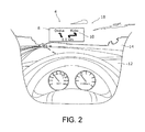
- FIG. 2 illustrates a display sample of an image 10 by the head-up display device 4 of FIG. 1 .
- the head-up display device 4 is mounted to an automobile 6, and includes the projector 2 and a combiner 8 (also referred to as "projection surface 8" below).
- the projector 2 projects the image 10 onto the combiner 8, and is disposed in a dashboard 12 of the automobile 6.
- the combiner 8, for example, is constructed by a half mirror or such, and is disposed on a front glass 14 of the automobile 6.
- the image 10 projected by the projector 2 is reflected towards a driver 16 by the combiner 8.
- the driver 16 is able to view a virtual image, namely the image 10, that is superimposed on to a scenery 18 in front of the front glass 14.
- the driver 16 may visually recognize particular information without averting his/her vision while driving the automobile 6.
- information relating to car navigation for example, information that displays the road splitting into a route towards Osaka and a route towards Kobe at a point 10 km from the current location
- the combiner 8 is displayed to the combiner 8 as the image 10.
- FIG. 3 is a block diagram schematically illustrating a configuration of the projector 2 according to the first embodiment.
- the projector 2 is a laser projector that projects a color image 10 (refer to FIG. 2 ) onto the projection surface 8 by synthesizing laser beams of a red component (R), a green component (G) and a blue component (B), and irradiating the synthesized laser beam onto the projection surface 8 while scanning.
- a color image 10 (refer to FIG. 2 ) onto the projection surface 8 by synthesizing laser beams of a red component (R), a green component (G) and a blue component (B), and irradiating the synthesized laser beam onto the projection surface 8 while scanning.
- the projector 2 includes a first laser diode 20, a second laser diode 22, a third laser diode 24, a first optical element 26, a second optical element 28, a third optical element 30, a first dichroic mirror 32, a second dichroic mirror 34, a lens 36, a mirror 38 and a projection component 40.
- each of the first laser diode 20, the second laser diode 22 and the third laser diode 24 is a light source that emits a laser beam of a monochromatic color with a particular wavelength.
- the first laser diode 20 emits the laser beam of the red component
- the second laser diode 22 emits the laser beam of the green component
- the third laser diode 24 emits the laser beam of the blue component.
- the laser beams respectively emitted by the first laser diode 20, the second laser diode 22 and the third laser diode 24 are divergent beams, and the beam shapes thereof are elliptic shape.
- "elliptic shape” does not only strictly mean elliptic shape, but also includes shapes that are substantially elliptic shape.
- the first optical element 26, the second optical element 28 and the third optical element 30 are each an example of an optical element (lens) having a beam shaping function and a collimate function.
- the beam shaping function refers to shaping the beam shape of the laser beam from an elliptic shape to a circular shape.
- the collimate function refers to converting the laser beam from a divergent beam into a parallel beam.
- "circular shape” does not only strictly mean circular shape, but also includes shapes that are substantially circularly shape.
- the first optical element 26, the second optical element 28 and the third optical element 30 are disposed corresponding to the first laser diode 20, the second laser diode 22 and the third laser diode 24 respectively. That is to say, the first optical element 26 converts the laser beam from the first laser diode 20 from a divergent beam into a parallel beam, and shapes the beam shape of the laser beam emitted by the first laser diode 20 from an elliptic shape to a circular shape. Likewise, the second optical element 28 converts the laser beam emitted by the second laser diode 22 from a divergent beam into a parallel beam, and shapes the beam shape of the laser beam emitted by the second laser diode 22 from an elliptic shape to a circular shape.
- the third optical element 30 converts the laser beam emitted by the third laser diode 24 from a divergent beam into a parallel beam, and shapes the beam shape of the laser beam emitted by the third laser diode 24 from an elliptic shape to a circular shape.
- the first optical element 26, the second optical element 28 and the third optical element 30 have particular features. These configurations are described later.
- the first dichroic mirror 32 and the second dichroic mirror 34 have optical characteristics of reflecting only a laser beam of a particular wavelength while allowing laser beams of other wavelengths to pass through. Specifically, the first dichroic mirror 32 reflects only the laser beam of the green component and allows the laser beams of other color components to pass through. The second dichroic mirror 34 reflects only the laser beam of the red component and allows laser beams of other color components to pass through.
- the first dichroic mirror 32 is disposed at an upstream side of an optical path of the laser beam
- the second dichroic mirror 34 is disposed at a downstream side of the optical path of the laser beam.
- the laser beam of the green component from the second laser diode 22 is reflected by the first dichroic mirror 32 after passing through the second optical element 28.
- the laser beam of the blue component from the third laser diode 24 passes through the first dichroic mirror 32 after passing through the third optical element 30. In this way, the laser beam of the green component and the laser beam of the blue component are synthesized at the first dichroic mirror 32.
- the laser beam of the red component from the first laser diode 20 is reflected by the second dichroic mirror 34 after passing through the first optical element 26.
- the lens 36 is a light condensing lens for condensing the light of the laser beam that exits out of the second dichroic mirror 34.
- the mirror 38 is a reflecting plate for reflecting the laser beam that was condensed by the lens 36, towards the projection component 40.
- the projection component 40 is for projecting the image 10 onto the projection surface 8 by irradiating the laser beam that is reflected by the mirror 38 onto the projection surface 8 while scanning.
- the projection component 40 has a first MEMS (micro electro mechanical systems) mirror 42 and a second MEMS mirror 44.
- the first MEMS mirror 42 swings at a relatively high speed in a horizontal direction.
- the second MEMS mirror 44 swings at a relatively low speed in a vertical direction.
- the first MEMS mirror 42 and the second MEMS mirror 44 respectively reflect the laser beams that are incident thereto, towards directions corresponding to their swing angles.
- the aforementioned laser beam that is reflected by the mirror 38 is reflected by the second MEMS mirror 44 after being reflected by the first MEMS mirror 42.
- the laser beam is irradiated onto the projection surface 8 in the horizontal direction and the vertical direction (that is to say two dimensionally) while scanning, by swing the first MEMS mirror 42 and the second MEMS mirror 44 in the horizontal direction and the vertical direction respectively.
- the projector 2 further includes a controller 46.
- the controller 46 controls driving currents respectively supplied to the first laser diode 20, the second laser diode 22 and the third laser diode 24 as well as controls swing angles of the first MEMS mirror 42 and the second MEMS mirror 44 according to image data that is transmitted from the outside.
- FIG. 4 is a perspective view illustrating a first optical element 26 according to a first embodiment.
- FIG. 5 is a side view illustrating a first optical element 26 according to a first embodiment.
- the configurations of the first optical element 26, the second optical element 28 and the third optical element 30 are the same, and therefore only the configuration of the first optical element 26 is described below.
- the first optical element 26 has an incidence surface 48 for the laser beam emitted by the first laser diode 20 to be incident thereto, and an emitting surface 50 for emitting the light incident to the incidence surface 48, and is formed, for example, by a transparent resin or the like.
- the incidence surface 48 and the emitting surface 50 are disposed to face opposite to each other in an optical axis direction (Z axis direction).
- a thickness T of the first optical element 26 in the optical axis direction (namely, the thickness from the incident surface 48 to the emitting surface 50), for example, is 1.48 mm.
- a lens effective diameter D of the first optical element 26, for example is 3.5 mm
- a numerical aperture (NA) of the first optical element 26, for example is 0.47.
- a first lens surface 52 having a convex shape is formed on the incident surface 48.
- a shape of the first lens surface 52 has a curvature in a first direction (Y axis direction), and does not have a curvature in a second direction (X axis direction) that is orthogonal to the first direction, and is a so-called cylindrical surface shape.
- a radius of curvature of the first lens surface 52 in the first direction preferably is greater than or equal to +100 mm, and for example, is +130 mm.
- crossed solid lines on the first lens surface 52 are imaginary lines to represent the cylindrical surface shape clearly.
- a second lens surface 54 having a convex shape is formed on the emitting surface 50.
- a shape of the second lens surface 54 is an aspherical shape.
- a radius of curvature of the second lens surface 54 for example, is -1.33, a conic constant, for example, is -0.93, a 4 th order aspherical coefficient, for example, is -0.026, a 6 th order aspherical coefficient, for example, is 2.825 x 10 -3 , an 8 th order aspherical coefficient, for example, is -2.494 x 10 -3 , and a 10 th order aspherical coefficient, for example, is 9.922 x 10 -5 .
- An unnecessary aberration that is generated due to the cylindrical surface shape of the first lens surface 52 can be reduced by the aspherical shape of the second lens surface 54.
- An orientation of the first optical element 26 is fixed relative to the first laser diode 20, such that the first direction of the first lens surface 52 is aligned with a long axis direction of the beam shape of the laser beam, and the second direction of the first lens surface 52 is substantially aligned with a short axis direction of the beam shape of the laser beam.
- a distance WD between the first optical element 26 and the first laser diode 20, for example, is 1.465 mm.
- the laser beam from the first laser diode 20 is incident to the first lens surface 52 of the first optical element 26 while diverging with a radiation angle ⁇ of about 50°.
- the numerical aperture of the first optical element 26 is 0.47, the laser beam from the first laser diode 20 that is diverging with the radiation angle ⁇ of about 50° can be incident to the first lens surface 52 effectively, and a utilization efficiency of the laser beam can be increased.
- the beam shape of the laser beam incident to the first lens surface 52 is expanded in the short axis direction by astigmatism generated in the laser beam through the first lens surface 52.
- the reasons are that the shape of the first lens surface 52 is a cylindrical surface, and a condensation property the second direction of the first lens surface 52 is lower than a condensation property in the first direction. In this way, the shape of the laser beam incident to the first lens surface 52 is shaped from the elliptic shape into a circular shape.
- the laser beam shaped by the first lens surface 52 is converted from a divergent beam into a parallel beam by being incident to the second lens surface 54.
- the beam shape of the laser beam emitted from the second lens surface becomes a parallel beam having a circular shape.
- the first optical element 26, the second optical element 28 and the third optical element 30 have the beam shaping function and the collimating function.
- the number of components can be reduced in an overall optical system that includes the first optical element 26, the second optical element 28 and the third optical element 30.
- the beam shape of the laser beam can be shaped while achieving miniaturization of the mentioned overall optical system.
- the first lens surface 52 is formed on the incident surface 48, and the second lens surface 54 is formed on the emitting surface 50.
- the second lens surface 54 may be formed on the incident surface 48, and the first lens surface 52 may be formed on the emitting surface 50.
- FIG. 6 is a graph illustrating comparison results of the light condensation property when a second lens surface 54 is formed on an emitting surface 50, and the light condensation property when a second lens surface 54 is formed on an incidence surface 48.
- a phase shift amount of the vertical axis is used as an indicator that represents the condensation property. That is to say, the closer the phase shift amount is to 0 at a screen position of 0mm, the higher the condensation property. Therefore, the light condensation property when the second lens surface 54 is formed on the emitting surface 50 may be understood to be higher than the light condensation property when the second lens surface 54 is formed on the incidence surface 48, as is apparent from to FIG. 6 .
- FIG. 7 is a graph illustrating a relationship of a lens thickness T of a first optical element 26 with a lens effective diameter D and with a radius of curvature of a second lens surface 54.
- a distance WD between the first optical element 26 and the first laser diode 20 is set to a fixed value (3.7 mm).
- the lens thickness T of the first optical element 26 is set to less than or equal to 1.75 mm, or, set the lens effective diameter D of the first optical element 26 to less than or equal to 3.5 mm to satisfy the relationship of the graph of FIG. 7 .
- FIG. 8 is a side view illustrating a first optical element 26A according to a second embodiment.
- the same reference numbers as the aforementioned first embodiment are used to describe the same components, and their description thereof is omitted.
- a shape of a second lens surface 54A that is formed on the emitting surface 50 is different compared to the aforementioned first embodiment.
- a shape of the second lens surface 54A is a spherical shape.
- a radius of curvature of the second lens surface 54A, for example, is -1.48 mm.
- the laser beam that is shaped by the first lens surface 52 is converted from a divergent beam into a parallel beam by be incident to the second lens surface 54A. Therefore, the same effect as the aforementioned first embodiment can be achieved by the first optical element 26A according to the second embodiment.
- FIG. 9 is a perspective view illustrating a first optical element 26B according to a third embodiment.
- FIG. 10 is a side view illustrating a first optical element 26B according to a third embodiment.
- a shape of a first lens surface 52B that has a convex shape formed on the incident surface 48B is different compared to the aforementioned first embodiment. That is to say, as shown in FIGs. 9 and 10 , a shape of the first lens surface 52B has a first radius of curvature in a first direction (Y axis direction), and has a second radius of curvature in a second direction (X axis direction) that is orthogonal to the first direction, and is a so-called biconic surface shape. The first radius of curvature and the second radius of curvature are different in size.
- a ratio of the first radius of curvature and the second radius of curvature is greater than or equal to 1:5.
- the first radius of curvature for example, is +130 mm
- the second radius of curvature for example, is +1380 mm.
- crossed solid lines on the first lens surface 52B are imaginary lines to more represent the biconic surface shape clearly.
- a shape of the second lens surface 54 that is formed on the emitting surface 50 is an aspherical shape.
- a radius of curvature of the second lens surface 54 for example, is -1.331
- a conic constant for example, is -0.933
- a 4 th order aspherical coefficient for example, is -0.026
- a 6 th order aspherical coefficient for example, is 2.921 x 10 -3
- an 8 th order aspherical coefficient for example, is -2.511 x 10 -3
- a 10 th order aspherical coefficient for example, is 4.188 x 10 -5 .
- a direction of the first optical element 26B is fixed relative to the first laser diode 20, such that the first direction of the first lens surface 52B is aligned with a long axis direction of the laser beam, and the second direction of the first lens surface 52B is aligned with a short axis direction of the laser beam.
- the beam shape of the laser beam incident to the first lens surface 52B is expanded in the short axis direction by astigmatism that is generated in the laser beam through the first lens surface 52B.
- the reasons are that the shape of the first lens surface 52B is the biconic surface shape and a condensation property in the second direction of the first lens surface 52B is lower than a condensation property in the first direction. In this way, the shape of the laser beam that is incident to the first lens surface 52B is shaped from the elliptic shape into a circular shape.
- an unnecessary aberration that is generated due to a difference of the shape of the first lens surface 52B and the shape of the second lens surface 54 can be further reduced compared to the aforementioned first embodiment, by making the shape of the first lens surface 52B a biconic shape.
- optical element and projector according to the first, the second and the third embodiments of the disclosure have been described above.
- the disclosure is not limited to the first to the third embodiments.
- the aforementioned first to third embodiments may be suitably combined.
- the projector 2 is mounted to the head up display device 4.
- the projector 2 may be adopted as a projector for projecting an image onto a screen that is disposed on, for example, a wall inside a room and the like.
- the head up display device 4 is mounted to the automobile 6.
- the head up display device 4 may be mounted to various types of transportation equipment such as an aircraft or a ship.
- the first lens surface 52 (52B) and the second lens surface 54 (54A) are both formed as a convex shape.
- the disclosure may be adapted as an optical element mounted to a projector.
Landscapes
- Physics & Mathematics (AREA)
- Optics & Photonics (AREA)
- General Physics & Mathematics (AREA)
- Engineering & Computer Science (AREA)
- Multimedia (AREA)
- Signal Processing (AREA)
- Projection Apparatus (AREA)
- Mechanical Optical Scanning Systems (AREA)
- Lenses (AREA)
Abstract
A projector (2) is provided, having a light source (20) emitting a laser beam; an optical element (26), which the laser beam emitted by the light source (20) passes through; a projection component (40), projecting an image onto a projection surface (8) by irradiating the laser beam emitted from the optical element (26) onto the projection surface (8) while scanning. The optical element (26) has an incident surface (48), where the laser beam emitted by the light source (20) is incident; and an emitting surface (50), where the laser beam incident to the incidence surface (48) is emitted. A first lens surface (52), shaping a beam shape of the laser beam from elliptic into circular by astigmatism generated in the laser beam, is formed on one of the incident and the emitting surfaces (48, 50), and a second lens surface (54), converting the laser beam from a divergent beam into a parallel beam, is formed on the other one of the incident the emitting surfaces (50, 48).
Description
- The disclosure relates to a projector.
- A projector that projects a color image on to a projection surface by synthesizing a laser beam of a red component (R), a laser beam of a green component (G) and a laser beam of a blue component (B), and irradiating the synthesized laser beam on to the projection surface while scanning is known in the art (for example, refer to
patent document 1, Japanese Laid Open Patent Publication No.2011-197217 - A conventional projector includes a first laser diode for generating the laser beam of the red component, a second laser diode for generating the laser beam of the green component, a third laser diode for generating the laser beam of the blue component, a first to a third collimating lenses where the laser beams from the first to the third laser diodes are incident thereto respectively, and a dichroic mirror for synthesizing the laser beams that exit out of the first to the third collimating lenses. The first to the third collimating lenses convert the laser beams from the first to the third laser diodes from divergent beams into parallel beams.
- Generally, a beam shape of the laser beam emitted from the laser diode is elliptic shaped. In a case where the laser beam having the elliptic shape beam shape is irradiated directly onto the projection surface, the display resolution of the image may deteriorate. Therefore, a shaping prism, for shaping the beam shape of the laser beam that is emitted out of the dichroic mirror from an elliptic shape into a circular shape, is disposed in the above mentioned conventional projector.
- However, in the above mentioned conventional projector, a size of the shaping prism is relatively large. Therefore, a problem arises where the entire optical system including the shaping prism becomes larger and consequently the entire projector becomes larger.
- In view of the above issues, the disclosure provides an optical element capable of shaping a beam shape of a laser beam while achieving miniaturization of an overall optical system, and provides a projector having the optical element.
- A projector according to an embodiment of the disclosure includes a light source, an optical element and a projection component. The light source emits a laser beam. The optical element, which the laser beam emitted by the light source passes through, includes an incident surface where the laser beam emitted by the light source is incident, and an emitting surface where the laser beam incident to the incidence surface is emitted. The projection component projects an image onto a projection surface by irradiating the laser beam that is emitted from the optical element onto the projection surface while scanning. A first lens surface, which shapes a beam shape of the laser beam that is emitted by the light source from an elliptic shape into a circular shape by astigmatism generated in the laser beam that is emitted by the light source, is formed on one of the incident surface and the emitting surface. A second lens surface, which converts the laser beam that is emitted by the light source from a divergent beam into a parallel beam, is formed on the other one of the incident surface and the emitting surface.
- According to the above embodiment, the first lens surface shapes the beam shape of the laser beam that is emitted by the light source from an elliptic shape into a circular shape (beam shaping function) by generating astigmatism in the laser beam that is emitted by the light source, and is formed on one of the incident surface and the emitting surface. The second lens surface, which converts the laser beam that is emitted by the light source from a divergent beam into a parallel beam (collimating function), is formed on the other one of the incident surface and the emitting surface. In this way, since the projector has both the beam shaping function and the collimating function, the number of components can be reduced in an overall optical system that includes the optical element in comparison with the conventional case of disposing the shaping prism and the collimating lens separately. As a result, the beam shape of the laser beam can be shaped while achieving miniaturization of the above mentioned overall optical system.
- In the projector according to an embodiment of the disclosure, the incidence surface and the emitting surface are disposed to face oppositely with each other in an optical axis direction.
- In the projector according to an embodiment of the disclosure, the beam shape of the laser beam emitted by the light source is shaped from the elliptic shape into the circular shape by expanding the beam shape of the laser beam emitted by the light source in a short axis direction.
- According to the above embodiment, when the beam shape of the laser beam emitted by the light source is shaped from the elliptic shape into the circular shape, the beam shape of the laser beam is expanded in the short axis direction. In this way, the beam shape of the laser beam may be shaped while securing a size of the overall beam radius.
- In the projector according to an embodiment of the disclosure, the laser beam shaped by the first lens surface is converted from a divergent beam into a parallel beam by being incident to the second lens surface.
- In the projector according to an embodiment of the disclosure, the first lens surface is formed on the incident surface and the second lens surface is formed on the emitting surface.
- According to the above embodiment, the laser beam condensation property by the second lens surface can be increased since the second lens surface is formed on the emitting surface.
- In the projector according to an embodiment of the disclosure, the first lens surface is formed on the emitting surface and the second lens surface is formed on the incident surface.
- In the projector according to an embodiment of the disclosure, a shape of the first lens surface is a cylindrical surface shape, and a shape of the second lens surface is a spherical shape or an aspherical shape.
- According to the above embodiment, the first lens surface is made to have a beam shaping function since the first lens surface is a cylindrical surface shape. In addition, the second lens surface is made to have a collimating function since the second lens surface is a spherical shape or an aspherical shape.
- In the projector according to an embodiment of the disclosure, the first lens surface has a curvature in a first direction that is orthogonal to the optical axis direction, and does not have a curvature in a second direction that is orthogonal to the optical axis direction and the first direction.
- In the projector according to an embodiment of the disclosure, a shape of the first lens surface is a biconic surface shape, and a shape of the second lens surface is a spherical shape or an aspherical shape.
- According to the above embodiment, the first lens surface is made to have a beam shaping function since the first lens surface is a biconic surface shape. In addition, the second lens surface is made to have a collimating function since the second lens surface is a spherical shape or an aspherical shape.
- In the projector according to an embodiment of the disclosure, the first lens surface has a first radius of curvature in a first direction that is orthogonal to the optical axis direction, and has a second radius of curvature in a second direction that is orthogonal to the optical axis direction and the first direction, and the first radius of curvature and the second radius of curvature are different.
- In the projector according to an embodiment of the disclosure, a ratio of the first radius of curvature and the second radius of curvature is greater than or equal to 1:5.
- In the projector according to an embodiment of the disclosure, the first radius of curvature is +130 mm, and the second radius of curvature is +1380 mm.
- In the projector according to an embodiment of the disclosure, a numerical aperture of the optical element is greater than or equal to 0.47.
- According to the above embodiment, when a typical laser diode that emits, for example, a laser beam with a radiation angle θ of about 50° is adopted, the laser beam from the laser diode can be incident to the incident surface effectively. As a result, a utilization efficiency of the laser beam can be increased.
- In the projector according to an embodiment of the disclosure, a lens effective diameter of the optical element is lesser than or equal to 3.5 mm.
- According to the above embodiment, the miniaturization of the overall optical system can be achieved while the distance between the optical element and the light source is secured since the lens effective diameter of the optical element is less than or equal to 3.5 mm.
- In the projector according to an embodiment of the disclosure, a lens thickness of the optical element from the incident surface to the emitting surface is less than or equal to 1.75 mm.
- According to the above embodiment, the miniaturization of the overall optical system can be achieved while the distance between the optical element and the light source is secured since the lens thickness of the optical element is less than or equal to 1.75 mm.
- In the projector according to an embodiment of the disclosure, a radius of curvature of the first lens surface in a first direction that is orthogonal to an optical axis direction is greater than or equal to 100 mm.
- In the projector according to an embodiment of the disclosure, the optical element is fixed relative to the light source, such that the first direction of the first lens surface is aligned with a long axis direction of the beam shape of the laser beam, and the second direction of the first lens surface is substantially aligned with a short axis direction of the beam shape of the laser beam.
- In the projector according to an embodiment of the disclosure, the light source and the optical element are respectively disposed in plural. The plurality of light sources emit laser beams respectively having different wavelengths, and the plurality of optical elements is disposed corresponding to each of the plurality of light sources.
- According to the above embodiment, since each of the plurality of optical elements is disposed corresponding to each of the plurality of light sources, each of the laser beams can be synthesized after a beam shape of the laser beams from each of the plurality of light sources is shaped and the laser beams are converted from a divergent beam into a parallel beam.
- A projector according to an embodiment of the disclosure may shape a beam shape of a laser beam while achieving miniaturization of the overall optical system.
-
-
FIG. 1 is to describe a configuration of a head up display device equipped with a projector according to a first embodiment. -
FIG. 2 illustrates a display sample of an image by the head-up display device ofFIG. 1 . -
FIG. 3 is a block diagram schematically illustrating a configuration of a projector according to a first embodiment. -
FIG. 4 is a perspective view illustrating a first optical element according to a first embodiment. -
FIG. 5 is a side view illustrating a first optical element according to a first embodiment. -
FIG. 6 is a graph illustrating comparison results of the light condensation property when a second lens surface is formed at an emitting surface, and the light condensation property when a second lens surface is formed at an incidence surface. -
FIG. 7 is a graph illustrating a relationship of a lens thickness of a first optical element with a lens effective diameter and with a radius of curvature of a second lens surface. -
FIG. 8 is a side view illustrating a first optical element according to a second embodiment. -
FIG. 9 is a perspective view illustrating a first optical element according to a third embodiment. -
FIG. 10 is a side view illustrating a first optical element according to a third embodiment. - Embodiments of the disclosure will be described in detail below accompanied by drawings. The embodiments described below are intended to illustrate a comprehensive or specific example. The numerical values, the shapes, the material, the components, the configuration and the connection form of the components set forth in the following embodiments are only examples, and should not be construed as limitations to the disclosure. In addition, regarding the components in the following embodiments, elements that are not recited in the independent claims are described as arbitrary components. Furthermore, each of the drawings do not necessarily illustrate the size or the dimension ratio and the like precisely.
- An optical element and a projector having the optical element according to a first embodiment is described below.
- A
projector 2 according to the first embodiment, for example, is mounted to a head-updisplay device 4. First, a configuration of the head-updisplay device 4 is described with reference toFIGs. 1 and2 .FIG. 1 is to describe a configuration of a head-updisplay device 4 equipped with theprojector 2 according to a first embodiment.FIG. 2 illustrates a display sample of animage 10 by the head-updisplay device 4 ofFIG. 1 . - As shown in
FIG. 1 , the head-updisplay device 4, for example, is mounted to anautomobile 6, and includes theprojector 2 and a combiner 8 (also referred to as "projection surface 8" below). Theprojector 2 projects theimage 10 onto thecombiner 8, and is disposed in adashboard 12 of theautomobile 6. Thecombiner 8, for example, is constructed by a half mirror or such, and is disposed on afront glass 14 of theautomobile 6. - The
image 10 projected by theprojector 2 is reflected towards adriver 16 by thecombiner 8. In this way, as shown inFIG. 2 , thedriver 16 is able to view a virtual image, namely theimage 10, that is superimposed on to ascenery 18 in front of thefront glass 14. As a result, thedriver 16 may visually recognize particular information without averting his/her vision while driving theautomobile 6. - In addition, in the example shown in
FIG. 2 , information relating to car navigation (for example, information that displays the road splitting into a route towards Osaka and a route towards Kobe at apoint 10 km from the current location) is displayed to thecombiner 8 as theimage 10. - Next, an overall configuration of the
projector 2 according to the first embodiment is described with reference toFIG. 3. FIG. 3 is a block diagram schematically illustrating a configuration of theprojector 2 according to the first embodiment. - The
projector 2 according to the first embodiment, is a laser projector that projects a color image 10 (refer toFIG. 2 ) onto theprojection surface 8 by synthesizing laser beams of a red component (R), a green component (G) and a blue component (B), and irradiating the synthesized laser beam onto theprojection surface 8 while scanning. - As shown in
FIG. 3 , theprojector 2 includes afirst laser diode 20, asecond laser diode 22, athird laser diode 24, a firstoptical element 26, a secondoptical element 28, a thirdoptical element 30, a firstdichroic mirror 32, a seconddichroic mirror 34, alens 36, amirror 38 and aprojection component 40. - For example, each of the
first laser diode 20, thesecond laser diode 22 and thethird laser diode 24 is a light source that emits a laser beam of a monochromatic color with a particular wavelength. Specifically, thefirst laser diode 20 emits the laser beam of the red component, thesecond laser diode 22 emits the laser beam of the green component, and thethird laser diode 24 emits the laser beam of the blue component. In addition, as shown in a later descriedFIG. 5 , the laser beams respectively emitted by thefirst laser diode 20, thesecond laser diode 22 and thethird laser diode 24 are divergent beams, and the beam shapes thereof are elliptic shape. In the disclosure, "elliptic shape" does not only strictly mean elliptic shape, but also includes shapes that are substantially elliptic shape. - The first
optical element 26, the secondoptical element 28 and the thirdoptical element 30 are each an example of an optical element (lens) having a beam shaping function and a collimate function. The beam shaping function refers to shaping the beam shape of the laser beam from an elliptic shape to a circular shape. The collimate function refers to converting the laser beam from a divergent beam into a parallel beam. In the disclosure, "circular shape" does not only strictly mean circular shape, but also includes shapes that are substantially circularly shape. - The first
optical element 26, the secondoptical element 28 and the thirdoptical element 30 are disposed corresponding to thefirst laser diode 20, thesecond laser diode 22 and thethird laser diode 24 respectively. That is to say, the firstoptical element 26 converts the laser beam from thefirst laser diode 20 from a divergent beam into a parallel beam, and shapes the beam shape of the laser beam emitted by thefirst laser diode 20 from an elliptic shape to a circular shape. Likewise, the secondoptical element 28 converts the laser beam emitted by thesecond laser diode 22 from a divergent beam into a parallel beam, and shapes the beam shape of the laser beam emitted by thesecond laser diode 22 from an elliptic shape to a circular shape. In addition, the thirdoptical element 30 converts the laser beam emitted by thethird laser diode 24 from a divergent beam into a parallel beam, and shapes the beam shape of the laser beam emitted by thethird laser diode 24 from an elliptic shape to a circular shape. Furthermore, in theprojector 2 according to the first embodiment, the firstoptical element 26, the secondoptical element 28 and the thirdoptical element 30 have particular features. These configurations are described later. - The first
dichroic mirror 32 and the seconddichroic mirror 34 have optical characteristics of reflecting only a laser beam of a particular wavelength while allowing laser beams of other wavelengths to pass through. Specifically, the firstdichroic mirror 32 reflects only the laser beam of the green component and allows the laser beams of other color components to pass through. The seconddichroic mirror 34 reflects only the laser beam of the red component and allows laser beams of other color components to pass through. - The first
dichroic mirror 32 is disposed at an upstream side of an optical path of the laser beam, and the seconddichroic mirror 34 is disposed at a downstream side of the optical path of the laser beam. The laser beam of the green component from thesecond laser diode 22 is reflected by the firstdichroic mirror 32 after passing through the secondoptical element 28. On the other hand, the laser beam of the blue component from thethird laser diode 24 passes through the firstdichroic mirror 32 after passing through the thirdoptical element 30. In this way, the laser beam of the green component and the laser beam of the blue component are synthesized at the firstdichroic mirror 32. - Furthermore, the laser beam of the red component from the
first laser diode 20 is reflected by the seconddichroic mirror 34 after passing through the firstoptical element 26. The laser beam of the green component and the laser beam of the blue component which are synthesized as mentioned above, pass through the seconddichroic mirror 34. In this way, the laser beam of the red component, the laser beam of the green component and the laser beam of the blue component are synthesized at the seconddichroic mirror 34. - The
lens 36 is a light condensing lens for condensing the light of the laser beam that exits out of the seconddichroic mirror 34. Themirror 38 is a reflecting plate for reflecting the laser beam that was condensed by thelens 36, towards theprojection component 40. - The
projection component 40 is for projecting theimage 10 onto theprojection surface 8 by irradiating the laser beam that is reflected by themirror 38 onto theprojection surface 8 while scanning. Theprojection component 40 has a first MEMS (micro electro mechanical systems)mirror 42 and asecond MEMS mirror 44. - The
first MEMS mirror 42 swings at a relatively high speed in a horizontal direction. Thesecond MEMS mirror 44 swings at a relatively low speed in a vertical direction. Thefirst MEMS mirror 42 and thesecond MEMS mirror 44 respectively reflect the laser beams that are incident thereto, towards directions corresponding to their swing angles. The aforementioned laser beam that is reflected by themirror 38 is reflected by thesecond MEMS mirror 44 after being reflected by thefirst MEMS mirror 42. When projecting theimage 10 onto theprojection surface 8, the laser beam is irradiated onto theprojection surface 8 in the horizontal direction and the vertical direction (that is to say two dimensionally) while scanning, by swing thefirst MEMS mirror 42 and thesecond MEMS mirror 44 in the horizontal direction and the vertical direction respectively. - As shown in
FIG. 3 , theprojector 2 further includes acontroller 46. Thecontroller 46 controls driving currents respectively supplied to thefirst laser diode 20, thesecond laser diode 22 and thethird laser diode 24 as well as controls swing angles of thefirst MEMS mirror 42 and thesecond MEMS mirror 44 according to image data that is transmitted from the outside. - Next, a configuration of the first
optical element 26 according to the first embodiment is described with reference toFIGs. 4 and5 .FIG. 4 is a perspective view illustrating a firstoptical element 26 according to a first embodiment.FIG. 5 is a side view illustrating a firstoptical element 26 according to a first embodiment. The configurations of the firstoptical element 26, the secondoptical element 28 and the thirdoptical element 30 are the same, and therefore only the configuration of the firstoptical element 26 is described below. - As shown in
FIGs. 4 and5 , the firstoptical element 26 has anincidence surface 48 for the laser beam emitted by thefirst laser diode 20 to be incident thereto, and an emittingsurface 50 for emitting the light incident to theincidence surface 48, and is formed, for example, by a transparent resin or the like. Theincidence surface 48 and the emittingsurface 50 are disposed to face opposite to each other in an optical axis direction (Z axis direction). A thickness T of the firstoptical element 26 in the optical axis direction (namely, the thickness from theincident surface 48 to the emitting surface 50), for example, is 1.48 mm. In addition, a lens effective diameter D of the firstoptical element 26, for example, is 3.5 mm, and a numerical aperture (NA) of the firstoptical element 26, for example, is 0.47. - As shown in
FIGs. 4 and5 , afirst lens surface 52 having a convex shape is formed on theincident surface 48. A shape of thefirst lens surface 52 has a curvature in a first direction (Y axis direction), and does not have a curvature in a second direction (X axis direction) that is orthogonal to the first direction, and is a so-called cylindrical surface shape. A radius of curvature of thefirst lens surface 52 in the first direction, preferably is greater than or equal to +100 mm, and for example, is +130 mm. InFIG. 4 , crossed solid lines on thefirst lens surface 52 are imaginary lines to represent the cylindrical surface shape clearly. - As shown in
FIG. 5 , asecond lens surface 54 having a convex shape is formed on the emittingsurface 50. A shape of thesecond lens surface 54 is an aspherical shape. A radius of curvature of thesecond lens surface 54, for example, is -1.33, a conic constant, for example, is -0.93, a 4th order aspherical coefficient, for example, is -0.026, a 6th order aspherical coefficient, for example, is 2.825 x 10⁻³, an 8th order aspherical coefficient, for example, is -2.494x 10 -3, and a 10th order aspherical coefficient, for example, is 9.922 x 10⁻⁵. An unnecessary aberration that is generated due to the cylindrical surface shape of thefirst lens surface 52 can be reduced by the aspherical shape of thesecond lens surface 54. - An orientation of the first
optical element 26 is fixed relative to thefirst laser diode 20, such that the first direction of thefirst lens surface 52 is aligned with a long axis direction of the beam shape of the laser beam, and the second direction of thefirst lens surface 52 is substantially aligned with a short axis direction of the beam shape of the laser beam. In addition, a distance WD between the firstoptical element 26 and thefirst laser diode 20, for example, is 1.465 mm. - As shown in
FIG. 5 , the laser beam from thefirst laser diode 20, for example, is incident to thefirst lens surface 52 of the firstoptical element 26 while diverging with a radiation angle θ of about 50°. By setting the numerical aperture of the firstoptical element 26 as 0.47, the laser beam from thefirst laser diode 20 that is diverging with the radiation angle θ of about 50° can be incident to thefirst lens surface 52 effectively, and a utilization efficiency of the laser beam can be increased. - As shown in
FIG. 5 , the beam shape of the laser beam incident to thefirst lens surface 52 is expanded in the short axis direction by astigmatism generated in the laser beam through thefirst lens surface 52. The reasons are that the shape of thefirst lens surface 52 is a cylindrical surface, and a condensation property the second direction of thefirst lens surface 52 is lower than a condensation property in the first direction. In this way, the shape of the laser beam incident to thefirst lens surface 52 is shaped from the elliptic shape into a circular shape. - Then, the laser beam shaped by the
first lens surface 52 is converted from a divergent beam into a parallel beam by being incident to thesecond lens surface 54. In this way, the beam shape of the laser beam emitted from the second lens surface becomes a parallel beam having a circular shape. - Next, an effect that is achieved by the first
optical element 26, the secondoptical element 28 and the thirdoptical element 30 according to the first embodiment is described. As mentioned above, the firstoptical element 26, the secondoptical element 28 and the thirdoptical element 30 have the beam shaping function and the collimating function. In this way, in comparison with the conventional case of disposing the shaping prism and the collimating lens additionally, the number of components can be reduced in an overall optical system that includes the firstoptical element 26, the secondoptical element 28 and the thirdoptical element 30. As a result, the beam shape of the laser beam can be shaped while achieving miniaturization of the mentioned overall optical system. - In the first embodiment, the
first lens surface 52 is formed on theincident surface 48, and thesecond lens surface 54 is formed on the emittingsurface 50. However, conversely, thesecond lens surface 54 may be formed on theincident surface 48, and thefirst lens surface 52 may be formed on the emittingsurface 50. - Here, with reference to
FIG. 6 , comparison of the light condensation property when thesecond lens surface 54 is formed on the emittingsurface 50, and the light condensation property when thesecond lens surface 54 is formed on theincidence surface 48 is considered.FIG. 6 is a graph illustrating comparison results of the light condensation property when asecond lens surface 54 is formed on an emittingsurface 50, and the light condensation property when asecond lens surface 54 is formed on anincidence surface 48. - In the comparison results shown in
FIG. 6 , a phase shift amount of the vertical axis is used as an indicator that represents the condensation property. That is to say, the closer the phase shift amount is to 0 at a screen position of 0mm, the higher the condensation property. Therefore, the light condensation property when thesecond lens surface 54 is formed on the emittingsurface 50 may be understood to be higher than the light condensation property when thesecond lens surface 54 is formed on theincidence surface 48, as is apparent from toFIG. 6 . - Next, parameters of the first
optical element 26 will be considered with reference toFIG. 7. FIG. 7 is a graph illustrating a relationship of a lens thickness T of a firstoptical element 26 with a lens effective diameter D and with a radius of curvature of asecond lens surface 54. However, in the graph shown inFIG. 7 , a distance WD between the firstoptical element 26 and thefirst laser diode 20 is set to a fixed value (3.7 mm). - For example, in a case when the numerical aperture of the first
optical element 26 is 0.47, and when the distance WD between the firstoptical element 26 and thefirst laser diode 20 is 3.7 mm, it is preferable to set the lens thickness T of the firstoptical element 26 to less than or equal to 1.75 mm, or, set the lens effective diameter D of the firstoptical element 26 to less than or equal to 3.5 mm to satisfy the relationship of the graph ofFIG. 7 . By setting the parameters of the firstoptical element 26 as aforementioned, miniaturization of the overall optical system can be achieved while the distance WD is secured. - Next, a configuration of the first
optical element 26A according to a second embodiment is described with reference toFIG. 8. FIG. 8 is a side view illustrating a firstoptical element 26A according to a second embodiment. In the following embodiments, the same reference numbers as the aforementioned first embodiment are used to describe the same components, and their description thereof is omitted. - In the first
optical element 26A according to the second embodiment, a shape of asecond lens surface 54A that is formed on the emittingsurface 50 is different compared to the aforementioned first embodiment. Namely, as is shown inFIG. 7 , a shape of thesecond lens surface 54A is a spherical shape. A radius of curvature of thesecond lens surface 54A, for example, is -1.48 mm. - Even with this configuration, similar to the aforementioned first embodiment, the laser beam that is shaped by the
first lens surface 52 is converted from a divergent beam into a parallel beam by be incident to thesecond lens surface 54A. Therefore, the same effect as the aforementioned first embodiment can be achieved by the firstoptical element 26A according to the second embodiment. - Next, a configuration of the first
optical element 26B according to the third embodiment is described with reference toFIGs. 9 and10 .FIG. 9 is a perspective view illustrating a firstoptical element 26B according to a third embodiment.FIG. 10 is a side view illustrating a firstoptical element 26B according to a third embodiment. - In the first
optical element 26B according to the third embodiment, a shape of afirst lens surface 52B that has a convex shape formed on theincident surface 48B is different compared to the aforementioned first embodiment. That is to say, as shown inFIGs. 9 and10 , a shape of thefirst lens surface 52B has a first radius of curvature in a first direction (Y axis direction), and has a second radius of curvature in a second direction (X axis direction) that is orthogonal to the first direction, and is a so-called biconic surface shape. The first radius of curvature and the second radius of curvature are different in size. Preferably, a ratio of the first radius of curvature and the second radius of curvature is greater than or equal to 1:5. The first radius of curvature, for example, is +130 mm, and the second radius of curvature, for example, is +1380 mm. InFIG. 9 , crossed solid lines on thefirst lens surface 52B are imaginary lines to more represent the biconic surface shape clearly. - Similar to the aforementioned first embodiment, a shape of the
second lens surface 54 that is formed on the emittingsurface 50 is an aspherical shape. A radius of curvature of thesecond lens surface 54, for example, is -1.331, a conic constant, for example, is -0.933, a 4th order aspherical coefficient, for example, is -0.026, a 6th order aspherical coefficient, for example, is 2.921 x 10 -3, and an 8th order aspherical coefficient, for example, is -2.511x 10⁻³, and a 10th order aspherical coefficient, for example, is 4.188 x 10⁻⁵. - A direction of the first
optical element 26B is fixed relative to thefirst laser diode 20, such that the first direction of thefirst lens surface 52B is aligned with a long axis direction of the laser beam, and the second direction of thefirst lens surface 52B is aligned with a short axis direction of the laser beam. - Similar to the aforementioned first embodiment, the beam shape of the laser beam incident to the
first lens surface 52B is expanded in the short axis direction by astigmatism that is generated in the laser beam through thefirst lens surface 52B. The reasons are that the shape of thefirst lens surface 52B is the biconic surface shape and a condensation property in the second direction of thefirst lens surface 52B is lower than a condensation property in the first direction. In this way, the shape of the laser beam that is incident to thefirst lens surface 52B is shaped from the elliptic shape into a circular shape. Furthermore, an unnecessary aberration that is generated due to a difference of the shape of thefirst lens surface 52B and the shape of thesecond lens surface 54 can be further reduced compared to the aforementioned first embodiment, by making the shape of thefirst lens surface 52B a biconic shape. - The optical element and projector according to the first, the second and the third embodiments of the disclosure have been described above. However, the disclosure is not limited to the first to the third embodiments. For example, the aforementioned first to third embodiments may be suitably combined.
- For example, in each of the above embodiments, examples were described where the
projector 2 is mounted to the head updisplay device 4. However, this is not a limitation, and for example, theprojector 2 may be adopted as a projector for projecting an image onto a screen that is disposed on, for example, a wall inside a room and the like. - For example, in each of the aforementioned embodiments, the head up
display device 4 is mounted to theautomobile 6. However, this is not a limitation, and for example, the head updisplay device 4 may be mounted to various types of transportation equipment such as an aircraft or a ship. - For example, in the aforementioned embodiments, the first lens surface 52 (52B) and the second lens surface 54 (54A) are both formed as a convex shape. However, this is not a limitation, and for example, at least one of the first lens surface 52 (52B) or the second lens surface 54 (54A) may be formed as a concave shape.
- The disclosure, for example, may be adapted as an optical element mounted to a projector.
-
- 2
- Projector
- 4
- Head Up Display Device
- 6
- Automobile
- 8
- Combiner
- 10
- Image
- 12
- Dashboard
- 14
- Front Glass
- 16
- Driver
- 18
- Scenery
- 20
- First Laser Diode
- 22
- Second Laser Diode
- 24
- Third Laser Diode
- 26, 26A, 26B
- First Optical Element
- 28
- Second Optical Element
- 30
- Third Optical Element
- 32
- First Dichroic Mirror
Claims (15)
- A projector (2), characterized in that the projector (2) comprises:a light source (20), emitting a laser beam;an optical element (26), which the laser beam emitted by the light source (20) passes through; anda projection component (40), projecting an image (10) onto a projection surface (8) by irradiating the laser beam that is emitted from the optical element (26) onto the projection surface (8) while scanning,the optical element (26) comprises:an incident surface (48), where the laser beam emitted by the light source (20) is incident; andan emitting surface (50), where the laser beam incident to the incidence surface (48) is emitted;wherein a first lens surface (52) in configured to shape a beam shape of the laser beam that is emitted by the light source (20) from an elliptic shape into a circular shape by astigmatism generated in the laser beam that is emitted by the light source (20), is formed on one of the incident surface (48) and the emitting surface (50), anda second lens surface (54) is configured to convert the laser beam that is emitted by the light source (20) from a divergent beam into a parallel beam, is formed on the other one of the incident surface (48) and the emitting surface (50).
- The projector (2) as claimed in claim 1, wherein the beam shape of the laser beam emitted by the light source (2) is shaped from the elliptic shape into the circular shape by expanding the beam shape of the laser beam from the light source (2) in a short axis direction.
- The projector (2) as claimed in claim 1 or 2, wherein the laser beam shaped by the first lens surface (52) is converted from a divergent beam into a parallel beam by being incident to the second lens surface (54).
- The projector (2) as claimed in any one of claims 1 to 3, wherein the first lens surface (52) is formed on the incident surface (48) and the second lens surface (54) is formed on the emitting surface (50), or
the first lens surface (52) is formed on the emitting surface (50) and the second lens surface (54) is formed on the incident surface (48). - The projector (2) as claimed in any one of claims 1-4, wherein a shape of the first lens surface (52) is a cylindrical surface shape, and a shape of the second lens surface (54) is a spherical shape or an aspherical shape.
- The projector (2) as claimed in any one of claims 1-5, wherein the first lens surface (52) has a curvature in a first direction that is orthogonal to an optical axis direction, and does not have a curvature in a second direction that is orthogonal to the optical axis direction and the first direction.
- The projector (2) as claimed in any one of claims 1-4, wherein a shape of the first lens surface (52) is a biconic surface shape, and a shape of the second lens surface (54) is a spherical shape or an aspherical shape.
- The projector (2) as claimed in any one of claims 1-4 and 7, wherein the first lens surface (52) has a first radius of curvature in a first direction that is orthogonal to an optical axis direction, and has a second radius of curvature in a second direction that is orthogonal to the optical axis direction and the first direction, and the first radius of curvature and the second radius of curvature are different.
- The projector (2) as claimed in claim 8, wherein a ratio of the first radius of curvature and the second radius of curvature is greater than or equal to 1:5.
- The projector (2) as claimed in any one of claims 1-9, wherein a numerical aperture of the optical element (26) is greater than or equal to 0.47.
- The projector (2) as claimed in claim 10 wherein a lens effective diameter (D) of the optical element (26) is less than or equal to 3.5 mm.
- The projector (2) as claimed in claim 10, wherein a lens thickness (T) of the optical element (26) from the incident surface (48) to the emitting surface (50) is less than or equal to 1.75 mm.
- The projector (2) as claimed in claim 12, wherein a radius of curvature of the first lens surface (52) in a first direction that is orthogonal to an optical axis direction is greater than or equal to 100 mm.
- The projector (2) as claimed in any one of claims 1-13, wherein the optical element (26) is fixed relative to the light source (20), such that a first direction of the first lens surface (52) is aligned with a long axis direction of the beam shape of the laser beam, and the second direction of the first lens surface (52) is substantially aligned with a short axis direction of the beam shape of the laser beam.
- The projector (2) as claimed in any one of claims 1-14, wherein the light source (20) and the optical element (26) are respectively disposed in plural, wherein each of the plurality of light sources (20) emits a laser beam having a wavelength that is different from each other, and each of the plurality of optical elements (26) is disposed corresponding to each of the plurality of light sources (20).
Applications Claiming Priority (1)
| Application Number | Priority Date | Filing Date | Title |
|---|---|---|---|
| JP2015120570A JP2017003922A (en) | 2015-06-15 | 2015-06-15 | Optical element and projector |
Publications (1)
| Publication Number | Publication Date |
|---|---|
| EP3106913A1 true EP3106913A1 (en) | 2016-12-21 |
Family
ID=56131400
Family Applications (1)
| Application Number | Title | Priority Date | Filing Date |
|---|---|---|---|
| EP16174332.3A Withdrawn EP3106913A1 (en) | 2015-06-15 | 2016-06-14 | Projector |
Country Status (4)
| Country | Link |
|---|---|
| US (1) | US20160366380A1 (en) |
| EP (1) | EP3106913A1 (en) |
| JP (1) | JP2017003922A (en) |
| CN (1) | CN106249529A (en) |
Families Citing this family (7)
| Publication number | Priority date | Publication date | Assignee | Title |
|---|---|---|---|---|
| US10771155B2 (en) | 2017-09-28 | 2020-09-08 | Soraa Laser Diode, Inc. | Intelligent visible light with a gallium and nitrogen containing laser source |
| US10466576B2 (en) * | 2017-10-20 | 2019-11-05 | Himax Technologies Limited | Method for controlling projector and associated electronic device |
| JP7034736B2 (en) * | 2018-01-25 | 2022-03-14 | スタンレー電気株式会社 | Light irradiation device and vehicle lighting equipment |
| JP7176439B2 (en) * | 2019-02-25 | 2022-11-22 | 住友電気工業株式会社 | optical module |
| CN112558299A (en) * | 2019-09-26 | 2021-03-26 | 光宝电子(广州)有限公司 | Head-up display device for augmented reality |
| CN111258163B (en) * | 2020-03-19 | 2021-04-13 | 无锡视美乐激光显示科技有限公司 | Light source device, light path structure design method and projection system |
| US20230001791A1 (en) * | 2021-06-30 | 2023-01-05 | Panasonic Intellectual Property Management Co., Ltd. | Display device |
Citations (3)
| Publication number | Priority date | Publication date | Assignee | Title |
|---|---|---|---|---|
| US6195208B1 (en) * | 1999-10-20 | 2001-02-27 | Bryan Kok Ann Ngoi | Single aspherical lens for de-astigmatism, collimation, and circulation of laser beams |
| JP2011197217A (en) | 2010-03-18 | 2011-10-06 | Konica Minolta Opto Inc | Beam shaping prism, integrated light source, projector device, and mobile apparatus |
| US20140333900A1 (en) * | 2012-01-26 | 2014-11-13 | JVC Kenwood Corporation | Projection-type display apparatus |
Family Cites Families (1)
| Publication number | Priority date | Publication date | Assignee | Title |
|---|---|---|---|---|
| CN103969933B (en) * | 2013-02-04 | 2016-08-31 | 深圳市光峰光电技术有限公司 | LASER Light Source, wavelength convert light source, conjunction radiant and projection display equipment |
-
2015
- 2015-06-15 JP JP2015120570A patent/JP2017003922A/en active Pending
-
2016
- 2016-06-14 EP EP16174332.3A patent/EP3106913A1/en not_active Withdrawn
- 2016-06-14 US US15/182,576 patent/US20160366380A1/en not_active Abandoned
- 2016-06-14 CN CN201610416523.3A patent/CN106249529A/en active Pending
Patent Citations (3)
| Publication number | Priority date | Publication date | Assignee | Title |
|---|---|---|---|---|
| US6195208B1 (en) * | 1999-10-20 | 2001-02-27 | Bryan Kok Ann Ngoi | Single aspherical lens for de-astigmatism, collimation, and circulation of laser beams |
| JP2011197217A (en) | 2010-03-18 | 2011-10-06 | Konica Minolta Opto Inc | Beam shaping prism, integrated light source, projector device, and mobile apparatus |
| US20140333900A1 (en) * | 2012-01-26 | 2014-11-13 | JVC Kenwood Corporation | Projection-type display apparatus |
Also Published As
| Publication number | Publication date |
|---|---|
| US20160366380A1 (en) | 2016-12-15 |
| JP2017003922A (en) | 2017-01-05 |
| CN106249529A (en) | 2016-12-21 |
Similar Documents
| Publication | Publication Date | Title |
|---|---|---|
| EP3106913A1 (en) | Projector | |
| JP6207850B2 (en) | Virtual image display device | |
| US9247221B2 (en) | Scanning type projector | |
| CN112639581B (en) | Head-up display and head-up display method | |
| US10976544B2 (en) | Display device and apparatus | |
| US9864263B2 (en) | Optical unit, optical apparatus using the same, light source apparatus, and projection display apparatus | |
| JP6468206B2 (en) | Head-up display device | |
| EP2908517A1 (en) | Laser beam-combining optical invention | |
| EP3684054B1 (en) | Projection apparatus and mobile object | |
| US11561396B2 (en) | Head-up display device and transportation device | |
| WO2019116730A1 (en) | Head-up display and moving body with head-up display mounted thereon | |
| WO2018123528A1 (en) | Display device and moving body carrying display device | |
| JP2014197041A (en) | Projector | |
| CN116125667A (en) | Multi-focal-plane head-up display system | |
| US10386031B2 (en) | Light device with movable scanning means and optical fiber | |
| CN111913339A (en) | Light source device, optical scanning device, display system, and moving object | |
| JP7000167B2 (en) | Image display device | |
| US10203091B2 (en) | Motor vehicle lighting system and motor vehicle | |
| JP2023531106A (en) | diffuser device | |
| JP2020154035A (en) | Projection device, display system, and movable body | |
| US11635618B2 (en) | Optical element, display system, and mobile object | |
| JP2021517280A (en) | How to assemble a two-lens optic, a beam combining module, a projector, and a two-lens optic | |
| JP2019066757A (en) | Image display device | |
| CN113767248A (en) | Light emitting module | |
| JP2019090987A5 (en) |
Legal Events
| Date | Code | Title | Description |
|---|---|---|---|
| PUAI | Public reference made under article 153(3) epc to a published international application that has entered the european phase |
Free format text: ORIGINAL CODE: 0009012 |
|
| STAA | Information on the status of an ep patent application or granted ep patent |
Free format text: STATUS: THE APPLICATION HAS BEEN PUBLISHED |
|
| AK | Designated contracting states |
Kind code of ref document: A1 Designated state(s): AL AT BE BG CH CY CZ DE DK EE ES FI FR GB GR HR HU IE IS IT LI LT LU LV MC MK MT NL NO PL PT RO RS SE SI SK SM TR |
|
| AX | Request for extension of the european patent |
Extension state: BA ME |
|
| STAA | Information on the status of an ep patent application or granted ep patent |
Free format text: STATUS: THE APPLICATION IS DEEMED TO BE WITHDRAWN |
|
| 18D | Application deemed to be withdrawn |
Effective date: 20170622 |