EP3106891A1 - Devices and methods for battery diagnostics - Google Patents
Devices and methods for battery diagnostics Download PDFInfo
- Publication number
- EP3106891A1 EP3106891A1 EP15176015.4A EP15176015A EP3106891A1 EP 3106891 A1 EP3106891 A1 EP 3106891A1 EP 15176015 A EP15176015 A EP 15176015A EP 3106891 A1 EP3106891 A1 EP 3106891A1
- Authority
- EP
- European Patent Office
- Prior art keywords
- state
- over
- temporary failure
- battery
- information
- Prior art date
- Legal status (The legal status is an assumption and is not a legal conclusion. Google has not performed a legal analysis and makes no representation as to the accuracy of the status listed.)
- Withdrawn
Links
- 238000000034 method Methods 0.000 title description 6
- 238000001514 detection method Methods 0.000 claims abstract description 32
- 238000013024 troubleshooting Methods 0.000 claims description 51
- 238000007599 discharging Methods 0.000 claims description 28
- 230000005856 abnormality Effects 0.000 description 5
- 230000002159 abnormal effect Effects 0.000 description 4
- 238000010586 diagram Methods 0.000 description 3
- 238000004891 communication Methods 0.000 description 2
- 230000004075 alteration Effects 0.000 description 1
- 238000003745 diagnosis Methods 0.000 description 1
- 238000005516 engineering process Methods 0.000 description 1
- 238000012986 modification Methods 0.000 description 1
- 230000004048 modification Effects 0.000 description 1
Images


Classifications
-
- G—PHYSICS
- G01—MEASURING; TESTING
- G01R—MEASURING ELECTRIC VARIABLES; MEASURING MAGNETIC VARIABLES
- G01R31/00—Arrangements for testing electric properties; Arrangements for locating electric faults; Arrangements for electrical testing characterised by what is being tested not provided for elsewhere
- G01R31/36—Arrangements for testing, measuring or monitoring the electrical condition of accumulators or electric batteries, e.g. capacity or state of charge [SoC]
- G01R31/392—Determining battery ageing or deterioration, e.g. state of health
-
- G—PHYSICS
- G01—MEASURING; TESTING
- G01R—MEASURING ELECTRIC VARIABLES; MEASURING MAGNETIC VARIABLES
- G01R31/00—Arrangements for testing electric properties; Arrangements for locating electric faults; Arrangements for electrical testing characterised by what is being tested not provided for elsewhere
- G01R31/36—Arrangements for testing, measuring or monitoring the electrical condition of accumulators or electric batteries, e.g. capacity or state of charge [SoC]
- G01R31/371—Arrangements for testing, measuring or monitoring the electrical condition of accumulators or electric batteries, e.g. capacity or state of charge [SoC] with remote indication, e.g. on external chargers
Definitions
- the disclosure relates generally to devices and methods for detecting the state of a battery, and more particularly it relates to devices and methods for determining an abnormal state and providing troubleshooting suggestions according to the detected state of the battery.
- the communication path is configured to read and write the state between the battery and the electronic device.
- the self-protection mechanism of the battery When the self-protection mechanism of the battery is activated due to an abnormality, the electronic device stops charging the battery and generates abnormal signals.
- the user usually has no idea what kind of abnormality is affecting the battery, and has no idea how to eliminate the root cause of the abnormality either, according to the abnormal signals generated by the electronic device. Therefore, we urgently need devices and methods for determining the type of abnormality affecting a battery and providing appropriate troubleshooting suggestions.
- the invention provides a state-detection device and method for battery diagnostics.
- the invention further provides the state-detection device and method for generating a troubleshooting suggestion according to the battery diagnosis.
- An embodiment of a state-detection device adapted to a host, comprises: a battery, a gas gauge, a processor, and a display.
- the battery is operating in an operation state.
- the gas gauge is configured to instantly detect the operation state to store state information of the battery in a plurality of registers.
- the processor determines whether the battery is operating in a normal state, a temporary failure state, or a permanent failure state, according to the state information to generate state-determination information.
- the processor further determines whether the temporary failure state is an over-temperature state, an over-voltage state, or an over-current state, according to a first value, a second value, and a third value, respectively, of the state information.
- the display is configured to display the state-determination information.
- the processor further determines whether the operation state is either a charging state or a discharging state according to whether a charger is coupled to the host or not.
- the processor determines whether the temporary failure state is the over-temperature state based on an Over Temperature Alarm bit; determines whether the temporary failure state is the over-voltage state based on a Cell Overvoltage Condition bit; and determines whether the temporary failure state is the over-current state based on a Charge Overcurrent Condition bit.
- the processor determines whether the temporary failure state is the over-temperature state based on an Over Temperature Alarm bit, or whether the temporary failure state is the over-current state based on a Discharge Overcurrent Condition bit.
- the processor when the operation state is the temporary failure state, the processor further displays, on the display, a troubleshooting suggestion corresponding to the over-temperature state, the over-voltage state, or the over-current state, so that the user is able to put the operation state back to the normal state according to the troubleshooting suggestion.
- the processor accesses the state information of the registers in a predetermined time interval a predetermined number of times, and determines that the operation state of the battery is either the normal state, the temporary failure state, or the permanent failure state, according to the state information that has been accessed a predetermined number of times.
- the processor determines whether the temporary failure state is the over-temperature state, the over-voltage state, or the over-current state, according to the state information that has been accessed the predetermined number of times.
- An embodiment of a state detection method adapted for a battery of a host, comprises: instantly detecting an operation state to be state information; storing the state information in a plurality of registers; determining, according to the state information, that the battery is operating in either a normal state, a temporary failure state, or a permanent failure state to generate state-determination information; when the battery is operating in the temporary failure state, determining whether the temporary failure state is an over-temperature state, an over-voltage state, or an over-current state according to a first value, a second value, and a third value, respectively, of the state information; and displaying the state-determination information by a display.
- An embodiment of the state detection method further comprises: determining whether the operation state is a charging state or a discharging state according to whether a charger is coupled to the host or not.
- the state detection method comprises determining whether the temporary failure state is the over-temperature state or not, based on an Over Temperature Alarm bit; determining whether the temporary failure state is the over-voltage state or not, based on a Cell Overvoltage Condition bit; and determining whether the temporary failure state is the over-current state or not, based on a Charge Overcurrent Condition bit.
- An embodiment of the state detection method further comprises: when the operation state is the temporary failure state of the discharging state, determining whether the temporary failure state is the over-temperature state or not based on the Over Temperature Alarm bit; and determining whether the temporary failure state is the over-current state or not based on a Discharge Overcurrent Condition bit.
- An embodiment of the state detection method further comprises: when the operation state is the temporary failure state, displaying a troubleshooting suggestion corresponding to each of the over-temperature state, the over-voltage state, and the over-current state by the display, so that the user is able to put the operation state back to the normal state according to the troubleshooting suggestion.
- An embodiment of the state detection method further comprises: accessing the state information of the registers in a predetermined interval a predetermined number of times; determining that the operation state of the battery is either the normal state, the temporary failure state, or the permanent failure state according to the state information that has been accessed the predetermined number of times; and when the operation state is the temporary failure state, determining whether the temporary failure state is the over-temperature state, the over-voltage state, or the over-current state according to the state information that has been accessed the predetermined number of times.
- Fig. 1 is a block diagram of the state-detection device in accordance with an embodiment of the invention.
- the host 10 includes the state-detection device 100 and is coupled to the charger 20.
- the host 10 can be a notebook computer, a hand-held electronic device, or any electronic device with a battery.
- the state-detection device 100 includes the battery 101, the gas gauge 102, the processor 103, and the display 104. The detailed function of the state-detection device 100 will be described in the following paragraphs.
- the battery 101 is operating in an operation state.
- the gas gauge 102 is configured to detect the operation state of the battery 101, and stores the operation information of the battery 101 in a plurality of registers (not shown in Fig. 1 ).
- the registers which store the operation information, are located in the gas gauge 102.
- the gas gauge 102 instantly detects the operation state of the battery 101 and instantly updates the operation information stored in the registers.
- the registers are not limited to being located in the gas gauge 102.
- the processor 103 determines that the battery 101 will operate in either the normal state, the temporary failure state, or the permanent failure state, to generate the state-determination information, according to an embodiment of the invention. According to an embodiment of the invention, the processor 103 displays the state-determination information to the user by using the display 104. According to an embodiment of the invention, the processor 103 further detects whether the charger 20 is coupled to the host 10 or not to determine whether the battery 101 is in the charging state or the discharging state.
- the processor 103 decodes the state information and, according to the decoded state information, the processor 103 determines whether the battery 101 is operating in the normal state, the temporary failure state, or the permanent failure state to generate the state-determination information.
- the state-determination information is displayed by the display 104.
- the processor 103 displays the troubleshooting suggestion by the display 104.
- the normal state, the temporary failure state, and the permanent state will be individually described in the following paragraphs.
- Table 1 shows the state information, the state-determination information, and the troubleshooting suggestion of the battery 101, which are displayed by the display 104, in accordance with an embodiment of the invention.
- the battery life, the battery count, the battery capacity, the battery current, the battery voltage, and the battery temperature are obtained by the processor 103 accessing the state information of the battery 101 which is stored in the registers.
- the charging or discharging state of the battery 101 shown in Table 1 is determined by the processor 103.
- the processor 103 determines that the battery 101 is operating in either the charging state or the discharging state based on whether the charger 20 is coupled to the host 10 or not.
- the processor 103 accesses the state information in the registers in a predetermined time interval a predetermined number of times to determine whether the operation state of the battery 101 is the normal state, the temporary failure state, or the permanent failure state.
- the predetermined time interval is 1 minute, and the predetermined number of times is 3 times.
- the user is able to adjust the predetermined time interval and the predetermined number of times. As shown in Table 1, since the error code is not displayed, it represents that there is no abnormality with the battery 101, so that the state-determination information shows that the battery 101 is operating in the normal state, and there are no troubleshooting suggestions.
- the processor 103 When the battery 101 is operating in the temporary failure state, the processor 103 further distinguishes whether the temporary failure state is the temporary failure state of the charging state or the temporary failure state of the discharging state, based on whether the charger 20 is coupled to the host 10 or not. According to an embodiment of the invention, when the temporary failure state has occurred in the charging state, the processor 103 determines whether the temporary failure state is the over-temperature state, the over-voltage state, or the over-current state, according the first value, the second value, and the third value, respectively, of the state information stored in the registers. The first value, the second value, and the third value will be described in detail in the following description.
- the processor 103 determines that the temporary failure state is the over-temperature state or the over-current state according the first value and the fourth value, respectively, of the state information stored in the registers.
- the temporary failure state in the charging state, the temporary failure state is subdivided into the over-temperature state, the over-voltage state, and the over-current state; in the discharging state, the temporary failure state is subdivided into the over-temperature state and the over-current state.
- the processor 103 determines whether the temporary failure state is the over-temperature state, the over-voltage state, or the over-current state, by the respective bits of the registers which store the state information.
- Table 2 shows the state information, the state-determination information, and the troubleshooting suggestion displayed by the display 104 when the battery 101 is operating in the temporary failure state of the charging state, in accordance with an embodiment of the invention.
- Table 2 since the current temperature has been up to 64°C and the highest temperature has been up to 65°C, it represents that the temporary failure state at the time is caused by the host 10 automatically shutting down due to over-temperature protection. Therefore, the error code being TF means that the battery 101 is operating in the temporary failure state at the time, and the display 104 displays that the temporary failure state is the over-temperature state by the state-determination information.
- the user can release the temporary failure state by lowering the temperature down to 50°C, or below 50°C, according to the troubleshooting suggestion displayed by the display 104.
- the processor 103 determines whether the temporary failure state is the over-temperature state or not based on the Over Temperature Alarm (OTA) bit in the registers. According to another embodiment of the invention, the processor 103 determines whether the temporary failure state is the over-temperature state or not based on the 12 th bit of 0x16 register of the registers which store the operation information. Table 2 Battery and Charger State Information Current Max Min Battery Health 100% 100% 100% Battery Count 3 3 3 Battery Capacity 46% 46% 41% Battery Current Flow 517mA 1000mA 515mA Battery Voltage Flow 7400mV 7400mV 7200mV Battery Temperature Flow 64°C 65°C 25°C Battery Charging State Charging N.A. N.A.
- OTA Over Temperature Alarm
- Table 3 shows the state information, the state-determination information, and the troubleshooting suggestion displayed by the display 104 when the battery 101 is operating in the temporary failure state of the charging state, in accordance with another embodiment of the invention.
- Table 3 since the highest battery current has been up to 7000mA, it represents that the temporary failure state at the time is caused by the host 10 automatically shutting down due to over-current protection. Therefore, the error code being TF means that the battery 101 is operating in the temporary failure state at the time, and the display 104 displays that the temporary failure state is the over-current state by the state-determination information.
- the user can release the temporary failure state by shutting down the host 10 and removing the charger 20 for a predetermined period according to the troubleshooting suggestion displayed by the display 104.
- the predetermined period is 10 sec.
- the processor 103 determines whether the temporary failure state is the over-current state or not based on the Charge Overcurrent Condition (OCC) bit in the registers. According to another embodiment of the invention, the processor 103 determines whether the temporary failure state is the over-current state or not based on the 2 nd bit of 0x51 register of the registers which store the operation information.
- OCC Charge Overcurrent Condition
- Table 4 shows the state information, the state-determination information, and the troubleshooting suggestion displayed by the display 104 when the battery 101 is operating in the temporary failure state of the charging state, in accordance with another embodiment of the invention.
- Table 4 since the highest battery voltage has been up to 8600mV, it represents that the temporary failure state at the time is caused by the host 10 automatically shutting down due to over-voltage protection. Therefore, the error code being TF means that the battery 101 is operating in the temporary failure state at the time, and the display 104 displays that the temporary failure state is the over-voltage state by the state-determination information.
- the user can release the temporary failure state by shutting down the host 10 and removing the charger 20 for a predetermined period according to the troubleshooting suggestion displayed by the display 104.
- the predetermined period is 10 sec. Table 4 Battery and Charger State Information Current Max Min Battery Health 100% 100% 100% Battery Count 5 5 5 Battery Capacity 46% 46% 41% Battery Current Flow 517mA 1000mA 515mA Battery Voltage Flow 7400mV 8600mV 7200mV Battery Temperature Flow 38°C 38°C 25°C Battery Charging State Charging N.A. N.A. Detect 3 rd 2 nd 1 st Error Code TF TF N.A. State-Determination Information Over-Voltage State Troubleshooting Suggestion Shutdown and Remove the charger for a period
- the processor 103 determines whether the temporary failure state is the over-voltage state or not based on the Cell Overvoltage Condition (COV) bit in the registers. According to another embodiment of the invention, the processor 103 determines whether the temporary failure state is the over-voltage state or not based on the 1 st bit of 0x51 register of the registers which store the operation information.
- COV Cell Overvoltage Condition
- Table 5 shows the state information, the state-determination information, and the troubleshooting suggestion displayed by the display 104 when the battery 101 is operating in the temporary failure state of the discharging state, in accordance with an embodiment of the invention.
- Table 5 since the current temperature has been up to 64°C and the highest temperature has been up to 65°C, it represents that the temporary failure state at the time is caused by the host 10 automatically shutting down due to over-temperature protection. Therefore, the error code being TF means that the battery 101 is operating in the temporary failure state at the time, and the display 104 displays that the temporary failure state is the over-temperature state by the state-determination information.
- the user can release the temporary failure state by lowering the temperature down to 50°C, or below 50°C, according to the troubleshooting suggestion displayed by the display 104.
- the processor 103 determines whether the temporary failure state is the over-temperature state or not based on the Over Temperature Alarm (OTA) bit in the registers. According to another embodiment of the invention, the processor 103 determines whether the temporary failure state is the over-temperature state or not based on the 12 th bit of 0x16 register of the registers which store the operation information. That is, the processor 103 determines whether the temporary failure state of both the charging and discharging state is the over-temperature state or not based on the 12 th bit of 0x16 register of the registers which store the operation information.
- OTA Over Temperature Alarm
- Table 6 shows the state information, the state-determination information, and the troubleshooting suggestion displayed by the display 104 when the battery 101 is operating in the temporary failure state of the discharging state, in accordance with another embodiment of the invention.
- Table 6 since the highest battery current has been up to 7000mA, it represents that the temporary failure state at the time is caused by the host 10 automatically shutting down due to over-current protection. Therefore, the error code being TF means that the battery 101 is operating in the temporary failure state at the time, and the display 104 displays that the temporary failure state is the over-current state by the state-determination information. The user can release the temporary failure state according to the troubleshooting suggestion.
- the user can release the temporary failure state by shutting down the host 10 and removing the charger 20 for a predetermined period according to the troubleshooting suggestion displayed by the display 104.
- the predetermined period is 10 sec. Table 6 Battery and Charger State Information Current Max Min Battery Health 100% 100% 100% Battery Count 2 2 2 Battery Capacity 46° 46% 41% Battery Current Flow 1500mA 7000mA 515mA Battery Voltage Flow 7400mV 7400mV 7200mV Battery Temperature Flow 38°C 38°C 25°C Battery Charging State Discharging N.A. N.A. Detect 3 rd 2 nd 1 st Error Code TF TF TF State-Determination Information Over-Current State Troubleshooting Suggestion Shutdown and Remove the charger for a period
- the processor 103 determines whether the temporary failure state is the over-current state or not based on the Discharge Overcurrent Condition (OCD) bit in the registers. According to another embodiment of the invention, the processor 103 determines whether the temporary failure state is the over-current state or not based on the 4 th bit of 0x51 register of the registers which store the operation information.
- OCD Discharge Overcurrent Condition
- Table 7 shows the state information, the state-determination information, and the troubleshooting suggestion displayed by the display 104 when the battery 101 is operating in the permanent failure state of the discharging state, in accordance with an embodiment of the invention.
- the error code being PF means the battery 101 is operating in the permanent failure state, and that the battery 101 is abnormal due to another, unknown situation having occurred. Therefore, the state-determination information shows that the battery 101 is operating in the permanent failure state.
- the user can contact customer service to expel the phenomena according to the troubleshooting suggestion.
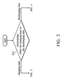
- Fig. 2 is a flow chart of the state detection method in accordance with an embodiment of the invention. In the following description, the flow chart will be described in detail with the block diagram of Fig. 1 .
- the processor 103 firstly determines that the battery 101 is operating in either the charging state or the discharging state (Step S21).
- the flow chart of Fig. 3 has been entered; when the battery 101 is operating in the discharging state, the flow chart of Fig. 4 has been entered.
- Fig. 3 is a flow chart of the state detection method during the charging state in accordance with an embodiment of the invention.
- the processor 103 determines whether the battery 101 is operating in the normal state, the temporary failure state, or the permanent failure state according to the state information stored in the registers (Step S301).
- Step S301 the state information stored in the registers.
- Step 302 the state detection method is stopped; when the permanent failure state has been determined (Step 303), it goes back to Step S301 in order to avoid any misjudgments.
- the processor 103 determines whether the temporary failure state is the over-temperature state or not (Step S305). According to an embodiment of the invention, the processor 103 determines whether the temporary failure state is the over-temperature state based on the Over Temperature Alarm (OTA) bit in the registers. According to another embodiment of the invention, the processor 103 determines whether the temporary failure state is the over-temperature state or not based on the 12 th bit of 0x16 register of the registers which store the operation information.
- OTA Over Temperature Alarm
- the processor 103 displays the corresponding troubleshooting suggestion by the display 104, according to the over-temperature state (Step S306).
- the troubleshooting suggestion of the over-temperature state is to lower the temperature down to 50°C, or below 50°C. The user can release the temporary failure state according to the troubleshooting suggestion displayed by the display 104.
- Step S307 when the processor 103 determines that the temporary failure state is not the over-temperature state, the processor 103 further determines whether the temporary failure state is the over-voltage state or not (Step S307). According to an embodiment of the invention, the processor 103 determines whether the temporary failure state of the charging state is the over-voltage state or not according to the Cell Overvoltage Condition (COV) bit of the registers. According to another embodiment of the invention, the processor 103 determines whether the temporary failure state of the charging state is the over-voltage state or not based on the 1 st bit of 0x51 register of the registers which store the operation information.
- COV Cell Overvoltage Condition
- Step S307 when the processor 103 determines that the temporary failure state is the over-voltage state, the processor 103 displays the corresponding troubleshooting suggestion by the display 104 according to the over-voltage state (Step S308).
- the troubleshooting suggestion of the over-voltage state is to shut down the host 10 and to remove the charger 20 for a predetermined period, and the user can release the temporary failure state according to the troubleshooting suggestion displayed by the display 104.
- the predetermined period is 10 seconds.
- Step S307 when the processor 103 determines that the temporary failure state is not the over-voltage state, the processor 103 further determines whether the temporary failure state is the over-current state or not (Step S309). According to an embodiment of the invention, the processor 103 determines whether the temporary failure state of the charging state is the over-current state or not according to the Charge Overcurrent Condition (OCC) bit of the registers. According to another embodiment of the invention, the processor 103 determines whether the temporary failure state of the charging state is the over-current state or not based on the 2 nd bit of 0x51 register of the registers which store the operation information.
- OCC Charge Overcurrent Condition
- Step S310 when the processor 103 determines that the temporary failure state is the over-current state, the processor 103 displays the corresponding troubleshooting suggestion by the display 104 according to the over-current state (Step S310).
- the troubleshooting suggestion of the over-current state is to shut down the host 10 and to remove the charger 20 for a predetermined period, and the user can release the temporary failure state according to the troubleshooting suggestion displayed by the display 104.
- the predetermined period is 10 seconds.
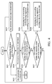
- Fig. 4 is a flow chart of the state detection method during the discharging state in accordance with an embodiment of the invention. Since only the over-temperature state and the over-current state should be detected in the temporary failure state of the discharging state, as shown in Fig. 4 , Step S401 to Step S406 are respectively identical to Step S301 to Step S306 in Fig. 3 , and Step 407 and Step 408 in Fig. 4 are respectively identical to Step S309 and Step S310 in Fig. 3 .
- the processor 103 determines whether the temporary failure state is the over-temperature state based on the Over Temperature Alarm (OTA) bit in the registers. According to another embodiment of the invention, the processor 103 determines whether the temporary failure state is the over-temperature state or not based on the 12 th bit of 0x16 register of the registers which store the operation information.
- OTA Over Temperature Alarm
- Step S406 the processor 103 displays the corresponding troubleshooting suggestion by the display 104 according to the over-temperature state (Step S406).
- the troubleshooting suggestion of the over-temperature state is to lower the temperature down to 50°C, or below 50°C, and the user can release the temporary failure state according to the troubleshooting suggestion displayed by the display 104.
- Step S407 the processor 103 determines whether the temporary failure state of the discharging state is the over-current state or not based on the Discharge Overcurrent Condition (OCD) bit in the registers. According to another embodiment of the invention, the processor 103 determines whether the temporary failure state of the discharging state is the over-current state or not based on the 4 th bit of 0x51 register of the registers which store the operation information.
- OCD Discharge Overcurrent Condition
- Step S407 the processor 103 displays the corresponding troubleshooting suggestion by the display 104 according to the over-current state (Step S408).
- the troubleshooting suggestion of the over-current state is to shut down the host 10 and to remove the charger 20 for a predetermined period, and the user can release the temporary failure state according to the troubleshooting suggestion displayed by the display 104.
- the predetermined period is 10 seconds.
- the invention discloses the reasons why the battery 101 is operating in the temporary failure state based on the operation state of the battery 101 which is detected by the gas gauge 102 and stored in the registers, and that the troubleshooting suggestion is provided to the user based on the reasons why the temporary failure state has occurred. Users can troubleshoot problems by themselves according to the troubleshooting suggestions, and can understand the status of the battery.
Landscapes
- Physics & Mathematics (AREA)
- General Physics & Mathematics (AREA)
- Charge And Discharge Circuits For Batteries Or The Like (AREA)
Abstract
Description
- This Application claims priority of Taiwan Patent Application No.
104119220, filed on Jun 15, 2015 - The disclosure relates generally to devices and methods for detecting the state of a battery, and more particularly it relates to devices and methods for determining an abnormal state and providing troubleshooting suggestions according to the detected state of the battery.
- In general, there is a communication path between a battery and an electronic device, and the communication path is configured to read and write the state between the battery and the electronic device. When the self-protection mechanism of the battery is activated due to an abnormality, the electronic device stops charging the battery and generates abnormal signals. However, the user usually has no idea what kind of abnormality is affecting the battery, and has no idea how to eliminate the root cause of the abnormality either, according to the abnormal signals generated by the electronic device. Therefore, we urgently need devices and methods for determining the type of abnormality affecting a battery and providing appropriate troubleshooting suggestions.
- For solving above problems, the invention provides a state-detection device and method for battery diagnostics. The invention further provides the state-detection device and method for generating a troubleshooting suggestion according to the battery diagnosis.
- An embodiment of a state-detection device, adapted to a host, comprises: a battery, a gas gauge, a processor, and a display. The battery is operating in an operation state. The gas gauge is configured to instantly detect the operation state to store state information of the battery in a plurality of registers. The processor determines whether the battery is operating in a normal state, a temporary failure state, or a permanent failure state, according to the state information to generate state-determination information. When the battery is operating in the temporary failure state, the processor further determines whether the temporary failure state is an over-temperature state, an over-voltage state, or an over-current state, according to a first value, a second value, and a third value, respectively, of the state information. The display is configured to display the state-determination information.
- In an embodiment, the processor further determines whether the operation state is either a charging state or a discharging state according to whether a charger is coupled to the host or not. When the operation state is the temporary failure state of the charging state, the processor determines whether the temporary failure state is the over-temperature state based on an Over Temperature Alarm bit; determines whether the temporary failure state is the over-voltage state based on a Cell Overvoltage Condition bit; and determines whether the temporary failure state is the over-current state based on a Charge Overcurrent Condition bit.
- In an embodiment, when the operation state is the temporary failure state of the discharging state, the processor determines whether the temporary failure state is the over-temperature state based on an Over Temperature Alarm bit, or whether the temporary failure state is the over-current state based on a Discharge Overcurrent Condition bit.
- In an embodiment, when the operation state is the temporary failure state, the processor further displays, on the display, a troubleshooting suggestion corresponding to the over-temperature state, the over-voltage state, or the over-current state, so that the user is able to put the operation state back to the normal state according to the troubleshooting suggestion.
- In an embodiment, the processor accesses the state information of the registers in a predetermined time interval a predetermined number of times, and determines that the operation state of the battery is either the normal state, the temporary failure state, or the permanent failure state, according to the state information that has been accessed a predetermined number of times. When the operation state is the temporary failure state, the processor determines whether the temporary failure state is the over-temperature state, the over-voltage state, or the over-current state, according to the state information that has been accessed the predetermined number of times.
- An embodiment of a state detection method, adapted for a battery of a host, comprises: instantly detecting an operation state to be state information; storing the state information in a plurality of registers; determining, according to the state information, that the battery is operating in either a normal state, a temporary failure state, or a permanent failure state to generate state-determination information; when the battery is operating in the temporary failure state, determining whether the temporary failure state is an over-temperature state, an over-voltage state, or an over-current state according to a first value, a second value, and a third value, respectively, of the state information; and displaying the state-determination information by a display.
- An embodiment of the state detection method further comprises: determining whether the operation state is a charging state or a discharging state according to whether a charger is coupled to the host or not. When the operation state is the temporary failure state of the charging state, the state detection method comprises determining whether the temporary failure state is the over-temperature state or not, based on an Over Temperature Alarm bit; determining whether the temporary failure state is the over-voltage state or not, based on a Cell Overvoltage Condition bit; and determining whether the temporary failure state is the over-current state or not, based on a Charge Overcurrent Condition bit.
- An embodiment of the state detection method further comprises: when the operation state is the temporary failure state of the discharging state, determining whether the temporary failure state is the over-temperature state or not based on the Over Temperature Alarm bit; and determining whether the temporary failure state is the over-current state or not based on a Discharge Overcurrent Condition bit.
- An embodiment of the state detection method further comprises: when the operation state is the temporary failure state, displaying a troubleshooting suggestion corresponding to each of the over-temperature state, the over-voltage state, and the over-current state by the display, so that the user is able to put the operation state back to the normal state according to the troubleshooting suggestion.
- An embodiment of the state detection method further comprises: accessing the state information of the registers in a predetermined interval a predetermined number of times; determining that the operation state of the battery is either the normal state, the temporary failure state, or the permanent failure state according to the state information that has been accessed the predetermined number of times; and when the operation state is the temporary failure state, determining whether the temporary failure state is the over-temperature state, the over-voltage state, or the over-current state according to the state information that has been accessed the predetermined number of times.
- A detailed description is given in the following embodiments with reference to the accompanying drawings.
- The invention can be more fully understood by reading the subsequent detailed description and examples with references made to the accompanying drawings, wherein:
-
Fig. 1 is a block diagram of the state-detection device in accordance with an embodiment of the invention; -
Fig. 2 is a flow chart of the state detection method in accordance with an embodiment of the invention; -
Fig. 3 is a flow chart of the state detection method in the charging state in accordance with an embodiment of the invention; and -
Fig. 4 is a flow chart of the state detection method in the discharging state in accordance with an embodiment of the invention. - The following description is of the best-contemplated mode of carrying out the invention. This description is made for the purpose of illustrating the general principles of the invention and should not be taken in a limiting sense. The scope of the invention is best determined by reference to the appended claims.
-
Fig. 1 is a block diagram of the state-detection device in accordance with an embodiment of the invention. As shown inFig. 1 , thehost 10 includes the state-detection device 100 and is coupled to thecharger 20. According to an embodiment of the invention, thehost 10 can be a notebook computer, a hand-held electronic device, or any electronic device with a battery. As shown inFig. 1 , the state-detection device 100 includes thebattery 101, thegas gauge 102, theprocessor 103, and thedisplay 104. The detailed function of the state-detection device 100 will be described in the following paragraphs. - According to an embodiment of the invention, the
battery 101 is operating in an operation state. Thegas gauge 102 is configured to detect the operation state of thebattery 101, and stores the operation information of thebattery 101 in a plurality of registers (not shown inFig. 1 ). According to an embodiment of the invention, the registers, which store the operation information, are located in thegas gauge 102. Thegas gauge 102 instantly detects the operation state of thebattery 101 and instantly updates the operation information stored in the registers. According to another embodiment of the information, the registers are not limited to being located in thegas gauge 102. - According to the state information stored in the registers, the
processor 103 determines that thebattery 101 will operate in either the normal state, the temporary failure state, or the permanent failure state, to generate the state-determination information, according to an embodiment of the invention. According to an embodiment of the invention, theprocessor 103 displays the state-determination information to the user by using thedisplay 104. According to an embodiment of the invention, theprocessor 103 further detects whether thecharger 20 is coupled to thehost 10 or not to determine whether thebattery 101 is in the charging state or the discharging state. - According to another embodiment of the invention, after accessing the state information in the registers, the
processor 103 decodes the state information and, according to the decoded state information, theprocessor 103 determines whether thebattery 101 is operating in the normal state, the temporary failure state, or the permanent failure state to generate the state-determination information. The state-determination information is displayed by thedisplay 104. When thebattery 101 is operating in either the temporary failure state or the permanent failure state, theprocessor 103 displays the troubleshooting suggestion by thedisplay 104. The normal state, the temporary failure state, and the permanent state will be individually described in the following paragraphs. - Table 1 shows the state information, the state-determination information, and the troubleshooting suggestion of the
battery 101, which are displayed by thedisplay 104, in accordance with an embodiment of the invention. As shown in Table 1, the battery life, the battery count, the battery capacity, the battery current, the battery voltage, and the battery temperature are obtained by theprocessor 103 accessing the state information of thebattery 101 which is stored in the registers. The charging or discharging state of thebattery 101 shown in Table 1 is determined by theprocessor 103. Theprocessor 103 determines that thebattery 101 is operating in either the charging state or the discharging state based on whether thecharger 20 is coupled to thehost 10 or not. - According to an embodiment of the invention, the
processor 103 accesses the state information in the registers in a predetermined time interval a predetermined number of times to determine whether the operation state of thebattery 101 is the normal state, the temporary failure state, or the permanent failure state. According to an embodiment of the invention, the predetermined time interval is 1 minute, and the predetermined number of times is 3 times. According to another embodiment of the invention, the user is able to adjust the predetermined time interval and the predetermined number of times. As shown in Table 1, since the error code is not displayed, it represents that there is no abnormality with thebattery 101, so that the state-determination information shows that thebattery 101 is operating in the normal state, and there are no troubleshooting suggestions.Table 1 Battery and Charger State Information Current Max Min Battery Health 100% 100% 100% Battery Count 6 6 6 Battery Capacity 46% 46% 41% Battery Current Flow 1000mA 1000mA 515mA Battery Voltage Flow 7400mV 7400mV 7200mV Battery Temperature Flow 38°C 38°C 25°C Battery Charging State Charging N.A. N.A. Detect 3rd 2nd 1st Error Code N.A. N.A. N.A. State-Determination Information Normal State Troubleshooting Suggestion N.A. - When the
battery 101 is operating in the temporary failure state, theprocessor 103 further distinguishes whether the temporary failure state is the temporary failure state of the charging state or the temporary failure state of the discharging state, based on whether thecharger 20 is coupled to thehost 10 or not. According to an embodiment of the invention, when the temporary failure state has occurred in the charging state, theprocessor 103 determines whether the temporary failure state is the over-temperature state, the over-voltage state, or the over-current state, according the first value, the second value, and the third value, respectively, of the state information stored in the registers. The first value, the second value, and the third value will be described in detail in the following description. - According to another embodiment of the invention, when the temporary failure state has occurred in the discharging state, the
processor 103 determines that the temporary failure state is the over-temperature state or the over-current state according the first value and the fourth value, respectively, of the state information stored in the registers. - That is, in the charging state, the temporary failure state is subdivided into the over-temperature state, the over-voltage state, and the over-current state; in the discharging state, the temporary failure state is subdivided into the over-temperature state and the over-current state. In addition, the
processor 103 determines whether the temporary failure state is the over-temperature state, the over-voltage state, or the over-current state, by the respective bits of the registers which store the state information. - Table 2 shows the state information, the state-determination information, and the troubleshooting suggestion displayed by the
display 104 when thebattery 101 is operating in the temporary failure state of the charging state, in accordance with an embodiment of the invention. As shown in Table 2, since the current temperature has been up to 64°C and the highest temperature has been up to 65°C, it represents that the temporary failure state at the time is caused by thehost 10 automatically shutting down due to over-temperature protection. Therefore, the error code being TF means that thebattery 101 is operating in the temporary failure state at the time, and thedisplay 104 displays that the temporary failure state is the over-temperature state by the state-determination information. According to an embodiment of the invention, the user can release the temporary failure state by lowering the temperature down to 50°C, or below 50°C, according to the troubleshooting suggestion displayed by thedisplay 104. - According to an embodiment of the invention, the
processor 103 determines whether the temporary failure state is the over-temperature state or not based on the Over Temperature Alarm (OTA) bit in the registers. According to another embodiment of the invention, theprocessor 103 determines whether the temporary failure state is the over-temperature state or not based on the 12th bit of 0x16 register of the registers which store the operation information.Table 2 Battery and Charger State Information Current Max Min Battery Health 100% 100% 100% Battery Count 3 3 3 Battery Capacity 46% 46% 41% Battery Current Flow 517mA 1000mA 515mA Battery Voltage Flow 7400mV 7400mV 7200mV Battery Temperature Flow 64°C 65°C 25°C Battery Charging State Charging N.A. N.A. Detect 3rd 2nd 1st Error Code TF TF N.A. State-Determination Information Over-Temperature State Troubleshooting Suggestion Temperature down to 50°C Table 3 Battery and Charger State Information Current Max Min Battery Health 100% 100% 100% Battery Count 2 2 2 Battery Capacity 46% 46% 41% Battery Current Flow 1500mA 7000mA 515mA Battery Voltage Flow 7400mV 7400mV 7200mV Battery Temperature Flow 38°C 38°C 25°C Battery Charging State Charging N.A. N.A. Detect 3rd 2nd 1st Error Code TF TF TF State-Determination Information Over-Current State Troubleshooting Suggestion Shutdown and Remove the charger for a period - Table 3 shows the state information, the state-determination information, and the troubleshooting suggestion displayed by the
display 104 when thebattery 101 is operating in the temporary failure state of the charging state, in accordance with another embodiment of the invention. As shown in Table 3, since the highest battery current has been up to 7000mA, it represents that the temporary failure state at the time is caused by thehost 10 automatically shutting down due to over-current protection. Therefore, the error code being TF means that thebattery 101 is operating in the temporary failure state at the time, and thedisplay 104 displays that the temporary failure state is the over-current state by the state-determination information. According to an embodiment of the invention, the user can release the temporary failure state by shutting down thehost 10 and removing thecharger 20 for a predetermined period according to the troubleshooting suggestion displayed by thedisplay 104. According to an embodiment of the invention, the predetermined period is 10 sec. - According to an embodiment of the invention, the
processor 103 determines whether the temporary failure state is the over-current state or not based on the Charge Overcurrent Condition (OCC) bit in the registers. According to another embodiment of the invention, theprocessor 103 determines whether the temporary failure state is the over-current state or not based on the 2nd bit of 0x51 register of the registers which store the operation information. - Table 4 shows the state information, the state-determination information, and the troubleshooting suggestion displayed by the
display 104 when thebattery 101 is operating in the temporary failure state of the charging state, in accordance with another embodiment of the invention. As shown in Table 4, since the highest battery voltage has been up to 8600mV, it represents that the temporary failure state at the time is caused by thehost 10 automatically shutting down due to over-voltage protection. Therefore, the error code being TF means that thebattery 101 is operating in the temporary failure state at the time, and thedisplay 104 displays that the temporary failure state is the over-voltage state by the state-determination information. According to an embodiment of the invention, the user can release the temporary failure state by shutting down thehost 10 and removing thecharger 20 for a predetermined period according to the troubleshooting suggestion displayed by thedisplay 104. According to an embodiment of the invention, the predetermined period is 10 sec.Table 4 Battery and Charger State Information Current Max Min Battery Health 100% 100% 100% Battery Count 5 5 5 Battery Capacity 46% 46% 41% Battery Current Flow 517mA 1000mA 515mA Battery Voltage Flow 7400mV 8600mV 7200mV Battery Temperature Flow 38°C 38°C 25°C Battery Charging State Charging N.A. N.A. Detect 3rd 2nd 1st Error Code TF TF N.A. State-Determination Information Over-Voltage State Troubleshooting Suggestion Shutdown and Remove the charger for a period - According to an embodiment of the invention, the
processor 103 determines whether the temporary failure state is the over-voltage state or not based on the Cell Overvoltage Condition (COV) bit in the registers. According to another embodiment of the invention, theprocessor 103 determines whether the temporary failure state is the over-voltage state or not based on the 1st bit of 0x51 register of the registers which store the operation information. - Table 5 shows the state information, the state-determination information, and the troubleshooting suggestion displayed by the
display 104 when thebattery 101 is operating in the temporary failure state of the discharging state, in accordance with an embodiment of the invention. As shown in Table 5, since the current temperature has been up to 64°C and the highest temperature has been up to 65°C, it represents that the temporary failure state at the time is caused by thehost 10 automatically shutting down due to over-temperature protection. Therefore, the error code being TF means that thebattery 101 is operating in the temporary failure state at the time, and thedisplay 104 displays that the temporary failure state is the over-temperature state by the state-determination information. According to an embodiment of the invention, the user can release the temporary failure state by lowering the temperature down to 50°C, or below 50°C, according to the troubleshooting suggestion displayed by thedisplay 104.Table 5 Battery and Charger State Information Current Max Min Battery Health 100% 100% 100% Battery Count 3 3 3 Battery Capacity 46% 46% 41% Battery Current Flow -517mA -1000mA -515mA Battery Voltage Flow 7400mV 8600mV 7200mV Battery Temperature Flow 64°C 65°C 25°C Battery Charging State Discharging N.A. N.A. Detect 3rd 2nd 1st Error Code TF TF N.A. State-Determination Information Over-Temperature State Troubleshooting Suggestion Temperature down to 50°C - According to an embodiment of the invention, the
processor 103 determines whether the temporary failure state is the over-temperature state or not based on the Over Temperature Alarm (OTA) bit in the registers. According to another embodiment of the invention, theprocessor 103 determines whether the temporary failure state is the over-temperature state or not based on the 12th bit of 0x16 register of the registers which store the operation information. That is, theprocessor 103 determines whether the temporary failure state of both the charging and discharging state is the over-temperature state or not based on the 12th bit of 0x16 register of the registers which store the operation information. - Table 6 shows the state information, the state-determination information, and the troubleshooting suggestion displayed by the
display 104 when thebattery 101 is operating in the temporary failure state of the discharging state, in accordance with another embodiment of the invention. As shown in Table 6, since the highest battery current has been up to 7000mA, it represents that the temporary failure state at the time is caused by thehost 10 automatically shutting down due to over-current protection. Therefore, the error code being TF means that thebattery 101 is operating in the temporary failure state at the time, and thedisplay 104 displays that the temporary failure state is the over-current state by the state-determination information. The user can release the temporary failure state according to the troubleshooting suggestion. - According to an embodiment of the invention, the user can release the temporary failure state by shutting down the
host 10 and removing thecharger 20 for a predetermined period according to the troubleshooting suggestion displayed by thedisplay 104. According to an embodiment of the invention, the predetermined period is 10 sec.Table 6 Battery and Charger State Information Current Max Min Battery Health 100% 100% 100% Battery Count 2 2 2 Battery Capacity 46° 46% 41% Battery Current Flow 1500mA 7000mA 515mA Battery Voltage Flow 7400mV 7400mV 7200mV Battery Temperature Flow 38°C 38°C 25°C Battery Charging State Discharging N.A. N.A. Detect 3rd 2nd 1st Error Code TF TF TF State-Determination Information Over-Current State Troubleshooting Suggestion Shutdown and Remove the charger for a period - According to an embodiment of the invention, the
processor 103 determines whether the temporary failure state is the over-current state or not based on the Discharge Overcurrent Condition (OCD) bit in the registers. According to another embodiment of the invention, theprocessor 103 determines whether the temporary failure state is the over-current state or not based on the 4th bit of 0x51 register of the registers which store the operation information. - Table 7 shows the state information, the state-determination information, and the troubleshooting suggestion displayed by the
display 104 when thebattery 101 is operating in the permanent failure state of the discharging state, in accordance with an embodiment of the invention. As shown in Table 7, although the battery current, the battery voltage, and the battery temperature are normal, the error code being PF means thebattery 101 is operating in the permanent failure state, and that thebattery 101 is abnormal due to another, unknown situation having occurred. Therefore, the state-determination information shows that thebattery 101 is operating in the permanent failure state. According to an embodiment of the invention, the user can contact customer service to expel the phenomena according to the troubleshooting suggestion.Table 7 Battery and Charger State Information Current Max Min Battery Health 100% 100% 100% Battery Count 6 6 6 Battery Capacity 46% 46% 41% Battery Current Flow 517mA 1000mA 515mA Battery Voltage Flow 7400mV 7400mV 7200mV Battery Temperature Flow 38°C 38°C 25°C Battery Charging State Charging N.A. N.A. Detect 3rd 2nd 1st Error Code PF PF PF. State-Determination Information Permanent Failure State Troubleshooting Suggestion Please Contact Customer Service -
Fig. 2 is a flow chart of the state detection method in accordance with an embodiment of the invention. In the following description, the flow chart will be described in detail with the block diagram ofFig. 1 . As shown inFig. 2 , theprocessor 103 firstly determines that thebattery 101 is operating in either the charging state or the discharging state (Step S21). When thebattery 101 is operating in the charging state, the flow chart ofFig. 3 has been entered; when thebattery 101 is operating in the discharging state, the flow chart ofFig. 4 has been entered. -
Fig. 3 is a flow chart of the state detection method during the charging state in accordance with an embodiment of the invention. First, theprocessor 103 determines whether thebattery 101 is operating in the normal state, the temporary failure state, or the permanent failure state according to the state information stored in the registers (Step S301). When the normal state has been determined (Step 302), the state detection method is stopped; when the permanent failure state has been determined (Step 303), it goes back to Step S301 in order to avoid any misjudgments. - When the temporary failure state has been determined (Step S304), the
processor 103 further determines whether the temporary failure state is the over-temperature state or not (Step S305). According to an embodiment of the invention, theprocessor 103 determines whether the temporary failure state is the over-temperature state based on the Over Temperature Alarm (OTA) bit in the registers. According to another embodiment of the invention, theprocessor 103 determines whether the temporary failure state is the over-temperature state or not based on the 12th bit of 0x16 register of the registers which store the operation information. - When the over-temperature has been determined in Step S305, the
processor 103 displays the corresponding troubleshooting suggestion by thedisplay 104, according to the over-temperature state (Step S306). According to an embodiment of the invention, the troubleshooting suggestion of the over-temperature state is to lower the temperature down to 50°C, or below 50°C. The user can release the temporary failure state according to the troubleshooting suggestion displayed by thedisplay 104. - Back to Step S305, when the
processor 103 determines that the temporary failure state is not the over-temperature state, theprocessor 103 further determines whether the temporary failure state is the over-voltage state or not (Step S307). According to an embodiment of the invention, theprocessor 103 determines whether the temporary failure state of the charging state is the over-voltage state or not according to the Cell Overvoltage Condition (COV) bit of the registers. According to another embodiment of the invention, theprocessor 103 determines whether the temporary failure state of the charging state is the over-voltage state or not based on the 1st bit of 0x51 register of the registers which store the operation information. - Back to Step S307, when the
processor 103 determines that the temporary failure state is the over-voltage state, theprocessor 103 displays the corresponding troubleshooting suggestion by thedisplay 104 according to the over-voltage state (Step S308). According to an embodiment of the invention, the troubleshooting suggestion of the over-voltage state is to shut down thehost 10 and to remove thecharger 20 for a predetermined period, and the user can release the temporary failure state according to the troubleshooting suggestion displayed by thedisplay 104. According to an embodiment of the invention, the predetermined period is 10 seconds. - Back to Step S307, when the
processor 103 determines that the temporary failure state is not the over-voltage state, theprocessor 103 further determines whether the temporary failure state is the over-current state or not (Step S309). According to an embodiment of the invention, theprocessor 103 determines whether the temporary failure state of the charging state is the over-current state or not according to the Charge Overcurrent Condition (OCC) bit of the registers. According to another embodiment of the invention, theprocessor 103 determines whether the temporary failure state of the charging state is the over-current state or not based on the 2nd bit of 0x51 register of the registers which store the operation information. - Back to Step S309, when the
processor 103 determines that the temporary failure state is the over-current state, theprocessor 103 displays the corresponding troubleshooting suggestion by thedisplay 104 according to the over-current state (Step S310). According to an embodiment of the invention, the troubleshooting suggestion of the over-current state is to shut down thehost 10 and to remove thecharger 20 for a predetermined period, and the user can release the temporary failure state according to the troubleshooting suggestion displayed by thedisplay 104. According to an embodiment of the invention, the predetermined period is 10 seconds. Back to Step 309, when theprocessor 103 determines that the temporary failure state is not the over-current state, it goes back to Step S301. -
Fig. 4 is a flow chart of the state detection method during the discharging state in accordance with an embodiment of the invention. Since only the over-temperature state and the over-current state should be detected in the temporary failure state of the discharging state, as shown inFig. 4 , Step S401 to Step S406 are respectively identical to Step S301 to Step S306 inFig. 3 , andStep 407 andStep 408 inFig. 4 are respectively identical to Step S309 and Step S310 inFig. 3 . - In Step S405, according to an embodiment of the invention, the
processor 103 determines whether the temporary failure state is the over-temperature state based on the Over Temperature Alarm (OTA) bit in the registers. According to another embodiment of the invention, theprocessor 103 determines whether the temporary failure state is the over-temperature state or not based on the 12th bit of 0x16 register of the registers which store the operation information. - When the over-temperature state has been determined in Step S405, the
processor 103 displays the corresponding troubleshooting suggestion by thedisplay 104 according to the over-temperature state (Step S406). According to an embodiment of the invention, the troubleshooting suggestion of the over-temperature state is to lower the temperature down to 50°C, or below 50°C, and the user can release the temporary failure state according to the troubleshooting suggestion displayed by thedisplay 104. - In Step S407, according to an embodiment of the invention, the
processor 103 determines whether the temporary failure state of the discharging state is the over-current state or not based on the Discharge Overcurrent Condition (OCD) bit in the registers. According to another embodiment of the invention, theprocessor 103 determines whether the temporary failure state of the discharging state is the over-current state or not based on the 4th bit of 0x51 register of the registers which store the operation information. - When the over-current state has been determined in Step S407, the
processor 103 displays the corresponding troubleshooting suggestion by thedisplay 104 according to the over-current state (Step S408). The troubleshooting suggestion of the over-current state is to shut down thehost 10 and to remove thecharger 20 for a predetermined period, and the user can release the temporary failure state according to the troubleshooting suggestion displayed by thedisplay 104. According to an embodiment of the invention, the predetermined period is 10 seconds. Back to Step S407, when theprocessor 103 determines that it is not the over-current state, it goes back to Step S401. - The invention discloses the reasons why the
battery 101 is operating in the temporary failure state based on the operation state of thebattery 101 which is detected by thegas gauge 102 and stored in the registers, and that the troubleshooting suggestion is provided to the user based on the reasons why the temporary failure state has occurred. Users can troubleshoot problems by themselves according to the troubleshooting suggestions, and can understand the status of the battery. - While the invention has been described by way of example and in terms of preferred embodiment, it is to be understood that the invention is not limited thereto. Those who are skilled in this technology can still make various alterations and modifications without departing from the scope and spirit of this invention. Therefore, the scope of the present invention shall be defined and protected by the following claims and their equivalents.
Claims (10)
- A state-detection device, adapted to a host, comprising:a battery, operating in an operation state;a gas gauge, configured to instantly detect the operation state to store state information of the battery in a plurality of registers;a processor, determining, according to the state information, whether the battery is operating in either a normal state, a temporary failure state, or a permanent failure state to generate state-determination information, wherein when the battery is operating in the temporary failure state, the processor further determines whether the temporary failure state is an over-temperature state, an over-voltage state, or an over-current state according to a first value, a second value, and a third value, respectively, of the state information; anda display, configured to display the state-determination information.
- The state-detection device of claim 1, wherein the processor further determines whether the operation state is a charging state or a discharging state according to whether a charger is coupled to the host or not, wherein when the operation state is the temporary failure state of the charging state, the processor determines whether the temporary failure state is the over-temperature state based on an Over Temperature Alarm bit, whether the temporary failure state is the over-voltage state based on a Cell Overvoltage Condition bit, or whether the temporary failure state is the over-current state based on a Charge Overcurrent Condition bit.
- The state-detection device of claim 2, wherein when the operation state is the temporary failure state of the discharging state, the processor determines whether the temporary failure state is the over-temperature state based on an Over Temperature Alarm bit, or whether the temporary failure state is the over-current state based on a Discharge Overcurrent Condition bit.
- The state-detection device of claim 1, wherein when the operation state is the temporary failure state, the processor further displays, on the display, a troubleshooting suggestion corresponding to the over-temperature state, the over-voltage state, or the over-current state, so that a user is able to put the operation state back to the normal state according to the troubleshooting suggestion.
- The state-detection device of claim 1, wherein the processor accesses the state information of the registers in a predetermined time interval a predetermined number of times, and determines that the operation state of the battery is the normal state, the temporary failure state, or the permanent failure state according to the state information that has been accessed the predetermined number of times, wherein when the operation state is the temporary failure state, the processor determines whether the temporary failure state is the over-temperature state, the over-voltage state, or the over-current state according to the state information that has been accessed the predetermined number of times.
- A state detection method, adapted for a battery of a host, comprising:instantly detecting an operation state to generate state information;storing the state information in a plurality of registers;determining, according to the state information, whether the battery is operating in a normal state, a temporary failure state, or a permanent failure state to generate state-determination information;when the battery is operating in the temporary failure state, determining whether the temporary failure state is an over-temperature state, an over-voltage state, or an over-current state, according to a first value, a second value, and a third value, respectively, of the state information; anddisplaying the state-determination information by a display.
- The state detection method of claim 6, further comprising:determining that the operation state is a charging state or a discharging state according to whether a charger is coupled to the host or not;when the operation state is the temporary failure state of the charging state, determining whether the temporary failure state is the over-temperature state or not based on an Over Temperature Alarm bit;determining whether the temporary failure state is the over-voltage state or not based on a Cell Overvoltage Condition bit; anddetermining whether the temporary failure state is the over-current state or not based on a Charge Overcurrent Condition bit.
- The state detection method of claim 7, further comprising:when the operation state is the temporary failure state of the discharging state, determining whether the temporary failure state is the over-temperature state or not based on the Over Temperature Alarm bit; anddetermining whether the temporary failure state is the over-current state or not based on a Discharge Overcurrent Condition bit.
- The state detection method of claim 6, further comprising:when the operation state is the temporary failure state, displaying, by the display, a troubleshooting suggestion corresponding to each of the over-temperature state, the over-voltage state, and the over-current state, so that a user is able to put the operation state back to the normal state according to the troubleshooting suggestion.
- The state detection method of claim 6, further comprising:accessing the state information of the registers in a predetermined interval a predetermined number of times;determining whether the operation state of the battery is the normal state, the temporary failure state, or the permanent failure state, according to the state information that has been accessed the predetermined number of times; andwhen the operation state is the temporary failure state, determining whether the temporary failure state is the over-temperature state, the over-voltage state, or the over-current state, according to the state information that has been accessed the predetermined number of times.
Applications Claiming Priority (1)
| Application Number | Priority Date | Filing Date | Title |
|---|---|---|---|
| TW104119220A TWI554771B (en) | 2015-06-15 | 2015-06-15 | State detection devices and methods thereof |
Publications (1)
| Publication Number | Publication Date |
|---|---|
| EP3106891A1 true EP3106891A1 (en) | 2016-12-21 |
Family
ID=53757976
Family Applications (1)
| Application Number | Title | Priority Date | Filing Date |
|---|---|---|---|
| EP15176015.4A Withdrawn EP3106891A1 (en) | 2015-06-15 | 2015-07-09 | Devices and methods for battery diagnostics |
Country Status (4)
| Country | Link |
|---|---|
| US (1) | US20160363633A1 (en) |
| EP (1) | EP3106891A1 (en) |
| CN (1) | CN106249151A (en) |
| TW (1) | TWI554771B (en) |
Cited By (1)
| Publication number | Priority date | Publication date | Assignee | Title |
|---|---|---|---|---|
| TWI712812B (en) * | 2019-10-23 | 2020-12-11 | 英研智能移動股份有限公司 | Battery protection method |
Families Citing this family (1)
| Publication number | Priority date | Publication date | Assignee | Title |
|---|---|---|---|---|
| CN112198471A (en) * | 2020-09-13 | 2021-01-08 | 南京宏泰半导体科技有限公司 | Real-time state detection device of efficient test system |
Citations (2)
| Publication number | Priority date | Publication date | Assignee | Title |
|---|---|---|---|---|
| WO2001028064A2 (en) * | 1999-10-13 | 2001-04-19 | Xicor, Inc. | Battery management system |
| US20130127626A1 (en) * | 2011-11-18 | 2013-05-23 | Hwan-Sung YOO | Apparatus for reporting fault of battery management system and energy storage system using the same |
Family Cites Families (19)
| Publication number | Priority date | Publication date | Assignee | Title |
|---|---|---|---|---|
| US6274950B1 (en) * | 1994-03-03 | 2001-08-14 | American Power Conversion | Battery communication system |
| SG117489A1 (en) * | 2004-05-13 | 2005-12-29 | Lin Goh Ken | Device to monitor engine performance and battery condition |
| CN100489543C (en) * | 2004-07-23 | 2009-05-20 | 广达电脑股份有限公司 | Electric power detection circuit with automatic feedback and overload protection functions |
| US7688033B2 (en) * | 2004-09-29 | 2010-03-30 | Panasonic Ev Energy Co., Ltd. | Method for detecting state of secondary battery and device for detecting state of secondary battery |
| CN1971301B (en) * | 2005-11-23 | 2010-08-25 | 比亚迪股份有限公司 | A battery detection system |
| JP2007236033A (en) * | 2006-02-27 | 2007-09-13 | Sony Corp | Battery pack and battery protection method |
| TWI280397B (en) * | 2006-06-30 | 2007-05-01 | Wistron Corp | Automatic battery test system and method of an electronic device |
| JP4611943B2 (en) * | 2006-07-13 | 2011-01-12 | Okiセミコンダクタ株式会社 | Semiconductor device |
| EP2130285A2 (en) * | 2007-03-26 | 2009-12-09 | The Gillette Company | Fast battery charger device and method |
| US20080238362A1 (en) * | 2007-03-26 | 2008-10-02 | The Gillette Company | Fast Battery Charger Device and Method |
| KR100956726B1 (en) * | 2007-07-20 | 2010-05-06 | 삼성전자주식회사 | Relay detects errors in asynchronously received map information or data |
| JP2011169831A (en) * | 2010-02-19 | 2011-09-01 | Mitsumi Electric Co Ltd | Device and method for detection of battery state |
| JP5462046B2 (en) * | 2010-03-26 | 2014-04-02 | セイコーインスツル株式会社 | Battery state monitoring circuit and battery device |
| JP5361824B2 (en) * | 2010-08-04 | 2013-12-04 | 三洋電機株式会社 | Pack battery and overcurrent detection method |
| JP5664223B2 (en) * | 2010-12-27 | 2015-02-04 | ソニー株式会社 | Charger |
| US9146280B2 (en) * | 2011-10-26 | 2015-09-29 | Industrial Technology Research Institute | Method and system for estimating a capacity of a battery |
| CN102447288A (en) * | 2011-12-05 | 2012-05-09 | 三门峡速达交通节能科技有限公司 | Power lithium-ion battery pack intelligent management system specially used for electric automobile |
| JP2014011567A (en) * | 2012-06-28 | 2014-01-20 | Fujitsu Ltd | Compensation device for power amplifier |
| JP6092542B2 (en) * | 2012-08-01 | 2017-03-08 | ローム株式会社 | CHARGE CONTROL DEVICE AND ELECTRONIC DEVICE USING THE SAME |
-
2015
- 2015-06-15 TW TW104119220A patent/TWI554771B/en not_active IP Right Cessation
- 2015-07-06 CN CN201510390639.XA patent/CN106249151A/en active Pending
- 2015-07-08 US US14/794,153 patent/US20160363633A1/en not_active Abandoned
- 2015-07-09 EP EP15176015.4A patent/EP3106891A1/en not_active Withdrawn
Patent Citations (2)
| Publication number | Priority date | Publication date | Assignee | Title |
|---|---|---|---|---|
| WO2001028064A2 (en) * | 1999-10-13 | 2001-04-19 | Xicor, Inc. | Battery management system |
| US20130127626A1 (en) * | 2011-11-18 | 2013-05-23 | Hwan-Sung YOO | Apparatus for reporting fault of battery management system and energy storage system using the same |
Cited By (1)
| Publication number | Priority date | Publication date | Assignee | Title |
|---|---|---|---|---|
| TWI712812B (en) * | 2019-10-23 | 2020-12-11 | 英研智能移動股份有限公司 | Battery protection method |
Also Published As
| Publication number | Publication date |
|---|---|
| TWI554771B (en) | 2016-10-21 |
| TW201643456A (en) | 2016-12-16 |
| CN106249151A (en) | 2016-12-21 |
| US20160363633A1 (en) | 2016-12-15 |
Similar Documents
| Publication | Publication Date | Title |
|---|---|---|
| AU2010281522B2 (en) | System and method for accessing diagnostic information | |
| CN112732477B (en) | Method for fault isolation by out-of-band self-checking | |
| US8063765B2 (en) | Consumer abuse detection system and method | |
| US9307495B2 (en) | Monitoring a battery in a portable electronic device | |
| CN103546643A (en) | A method and device for prompting a mobile smart device to drop and damage in time | |
| CN205881469U (en) | Fault detection equipment of electronic equipment and memory that is used for having a plurality of memory locations of standing transient fault and permanent fault | |
| US8035346B2 (en) | Battery protection circuit and protection method | |
| US8237399B2 (en) | System and method for controlling charging process of an electronic device | |
| CN104461809B (en) | A kind of fault information managing method and system | |
| CN105912143A (en) | Electronic device detecting method and electronic device | |
| ES2371089T3 (en) | RESEARCH OF THE SYSTEM CONTEXT IN CASE OF LOSS OF POWER. | |
| CN102904685B (en) | A kind of processing method of hardware table item check errors and device | |
| US20110057620A1 (en) | Charge/discharge protection circuit and discharging protection method | |
| US9590418B2 (en) | Apparatus for checking damage to surge protector and automatically changing surge protector | |
| CN108152746B (en) | A method and system for detecting battery activity of a backup power pack | |
| US20160363633A1 (en) | Devices and methods for battery diagnostics | |
| TWI540427B (en) | A System and Method for Displaying Battery Capacity | |
| CN106371019A (en) | Electric quantity display system and method | |
| US20090002900A1 (en) | System and method for protecting electronic devices | |
| JP2008104251A (en) | Power supply failure detection method | |
| CN113593628A (en) | Circuit and method for recording electrostatic discharge event, integrated circuit, and micro control unit | |
| CN104729536B (en) | A kind of debugging acid and adjustment method based on vehicle mounted guidance product | |
| CN112379832B (en) | Storage medium detection method and device | |
| JP2015208905A (en) | Image forming apparatus, image forming apparatus control method, and program | |
| CN120917414A (en) | Mobile terminal device, advice display method, and program |
Legal Events
| Date | Code | Title | Description |
|---|---|---|---|
| PUAI | Public reference made under article 153(3) epc to a published international application that has entered the european phase |
Free format text: ORIGINAL CODE: 0009012 |
|
| STAA | Information on the status of an ep patent application or granted ep patent |
Free format text: STATUS: THE APPLICATION HAS BEEN PUBLISHED |
|
| AK | Designated contracting states |
Kind code of ref document: A1 Designated state(s): AL AT BE BG CH CY CZ DE DK EE ES FI FR GB GR HR HU IE IS IT LI LT LU LV MC MK MT NL NO PL PT RO RS SE SI SK SM TR |
|
| AX | Request for extension of the european patent |
Extension state: BA ME |
|
| STAA | Information on the status of an ep patent application or granted ep patent |
Free format text: STATUS: REQUEST FOR EXAMINATION WAS MADE |
|
| 17P | Request for examination filed |
Effective date: 20170227 |
|
| RBV | Designated contracting states (corrected) |
Designated state(s): AL AT BE BG CH CY CZ DE DK EE ES FI FR GB GR HR HU IE IS IT LI LT LU LV MC MK MT NL NO PL PT RO RS SE SI SK SM TR |
|
| STAA | Information on the status of an ep patent application or granted ep patent |
Free format text: STATUS: EXAMINATION IS IN PROGRESS |
|
| 17Q | First examination report despatched |
Effective date: 20190222 |
|
| STAA | Information on the status of an ep patent application or granted ep patent |
Free format text: STATUS: THE APPLICATION HAS BEEN WITHDRAWN |
|
| 18W | Application withdrawn |
Effective date: 20190409 |