EP3106842B1 - Flow rate measurement device and wireless communication device - Google Patents
Flow rate measurement device and wireless communication device Download PDFInfo
- Publication number
- EP3106842B1 EP3106842B1 EP15749036.8A EP15749036A EP3106842B1 EP 3106842 B1 EP3106842 B1 EP 3106842B1 EP 15749036 A EP15749036 A EP 15749036A EP 3106842 B1 EP3106842 B1 EP 3106842B1
- Authority
- EP
- European Patent Office
- Prior art keywords
- distance
- long
- distance radio
- radiating conductor
- short
- Prior art date
- Legal status (The legal status is an assumption and is not a legal conclusion. Google has not performed a legal analysis and makes no representation as to the accuracy of the status listed.)
- Active
Links
- 238000004891 communication Methods 0.000 title claims description 100
- 238000005259 measurement Methods 0.000 title claims description 42
- 239000004020 conductor Substances 0.000 claims description 119
- 229910052751 metal Inorganic materials 0.000 claims description 22
- 239000002184 metal Substances 0.000 claims description 22
- 239000011347 resin Substances 0.000 claims description 19
- 229920005989 resin Polymers 0.000 claims description 19
- 230000005540 biological transmission Effects 0.000 description 9
- 239000000463 material Substances 0.000 description 6
- 238000000034 method Methods 0.000 description 5
- 230000005611 electricity Effects 0.000 description 3
- 230000000694 effects Effects 0.000 description 2
- 238000009434 installation Methods 0.000 description 2
- 238000004519 manufacturing process Methods 0.000 description 2
- 239000004065 semiconductor Substances 0.000 description 2
- 239000008399 tap water Substances 0.000 description 2
- 235000020679 tap water Nutrition 0.000 description 2
- XLYOFNOQVPJJNP-UHFFFAOYSA-N water Substances O XLYOFNOQVPJJNP-UHFFFAOYSA-N 0.000 description 2
- 239000004743 Polypropylene Substances 0.000 description 1
- 239000004676 acrylonitrile butadiene styrene Substances 0.000 description 1
- 229910052782 aluminium Inorganic materials 0.000 description 1
- XAGFODPZIPBFFR-UHFFFAOYSA-N aluminium Chemical compound [Al] XAGFODPZIPBFFR-UHFFFAOYSA-N 0.000 description 1
- 230000008878 coupling Effects 0.000 description 1
- 238000010168 coupling process Methods 0.000 description 1
- 238000005859 coupling reaction Methods 0.000 description 1
- 230000005684 electric field Effects 0.000 description 1
- 238000000691 measurement method Methods 0.000 description 1
- 230000005404 monopole Effects 0.000 description 1
- -1 polypropylene Polymers 0.000 description 1
- 229920001155 polypropylene Polymers 0.000 description 1
- 229910001220 stainless steel Inorganic materials 0.000 description 1
- 239000010935 stainless steel Substances 0.000 description 1
Images
Classifications
-
- H—ELECTRICITY
- H01—ELECTRIC ELEMENTS
- H01Q—ANTENNAS, i.e. RADIO AERIALS
- H01Q21/00—Antenna arrays or systems
- H01Q21/30—Combinations of separate antenna units operating in different wavebands and connected to a common feeder system
-
- G—PHYSICS
- G01—MEASURING; TESTING
- G01F—MEASURING VOLUME, VOLUME FLOW, MASS FLOW OR LIQUID LEVEL; METERING BY VOLUME
- G01F15/00—Details of, or accessories for, apparatus of groups G01F1/00 - G01F13/00 insofar as such details or appliances are not adapted to particular types of such apparatus
- G01F15/06—Indicating or recording devices
- G01F15/061—Indicating or recording devices for remote indication
- G01F15/063—Indicating or recording devices for remote indication using electrical means
-
- H—ELECTRICITY
- H01—ELECTRIC ELEMENTS
- H01Q—ANTENNAS, i.e. RADIO AERIALS
- H01Q1/00—Details of, or arrangements associated with, antennas
- H01Q1/12—Supports; Mounting means
- H01Q1/22—Supports; Mounting means by structural association with other equipment or articles
- H01Q1/2208—Supports; Mounting means by structural association with other equipment or articles associated with components used in interrogation type services, i.e. in systems for information exchange between an interrogator/reader and a tag/transponder, e.g. in Radio Frequency Identification [RFID] systems
- H01Q1/2233—Supports; Mounting means by structural association with other equipment or articles associated with components used in interrogation type services, i.e. in systems for information exchange between an interrogator/reader and a tag/transponder, e.g. in Radio Frequency Identification [RFID] systems used in consumption-meter devices, e.g. electricity, gas or water meters
-
- H—ELECTRICITY
- H01—ELECTRIC ELEMENTS
- H01Q—ANTENNAS, i.e. RADIO AERIALS
- H01Q7/00—Loop antennas with a substantially uniform current distribution around the loop and having a directional radiation pattern in a plane perpendicular to the plane of the loop
-
- H—ELECTRICITY
- H01—ELECTRIC ELEMENTS
- H01Q—ANTENNAS, i.e. RADIO AERIALS
- H01Q9/00—Electrically-short antennas having dimensions not more than twice the operating wavelength and consisting of conductive active radiating elements
- H01Q9/04—Resonant antennas
- H01Q9/0407—Substantially flat resonant element parallel to ground plane, e.g. patch antenna
Definitions
- the present invention relates to a flow rate measurement device that measures the flow rate of a measurement target, and a wireless communication device connected to the flow rate measurement device.
- a flow rate measurement device installed in a building such as a house measures the amount of usage of gas, electricity, water or the like, and the measured data is collected over wireless communication.
- a flow rate measurement device installed in a building such as a house measures the amount of usage of gas, electricity, water or the like, and the measured data is collected over wireless communication.
- a flow rate measurement device e.g., a gas meter
- a wireless communication device e.g., see PTL 1.
- the wireless communication device disclosed in PTL 1 includes a board-mounted planar antenna.
- the wireless communication device transmits, using the planar antenna, values measured by a flow rate measurement device to a wireless master unit which is distanced by several meters to several tens of meters.
- RFID Radio Frequency Identification
- PTL 3 discloses a broad band multi-resonant antenna utilizing capacitive coupling between multiple conductive plates for compact antenna applications.
- the antenna comprises a main patch which is electrically connected to a ground plane via a ground pin which is perpendicular to the ground plane.
- a feeding patch is arranged between the main patch and the ground plane and electrically connected to a transceiver by a feeding pin which is perpendicular to the feeding patch.
- the feeding pin extends through a hole included in the ground plane.
- PTL 4 discloses a semiconductor device having an antenna and an integrated circuit.
- An embodiment of the semiconductor device may include two antennas, that is, an antenna for receiving power and an antenna for receiving a signal.
- an antenna for receiving power a radio wave with a frequency of 13.56 MHz and a magnetic field are used
- a radio wave with a frequency of 950 MHz and an electric field are used.
- PTL 5 discloses a wireless device for a flow rate measurement device.
- a first radiating conductor and a second radiating conductor each are electrically connected to a circuit board by a feeding terminal which is perpendicular to the circuit board.
- the first and second radiating conductors are arranged with the same distance with respect to the circuit board.
- the present invention has been made to solve the problem described above, and provides a wireless communication device as defined in claim 1 that can support both long-distance wireless communication and near-distance wireless communication.
- a flow rate detecting device of the present invention includes: a wireless communication device according to the invention, a metal housing that is made of an electrically conductive material and houses a sensor that detects a flow rate of a measurement target; wherein a resin case of the wireless device according to the invention is disposed on the metal housing.
- the wireless communication device of the present invention includes: a long-distance radio radiating conductor that radiates high frequency signal waves for establishing long-distance communication; a short-distance radio radiating conductor that radiates high frequency signal waves for establishing short-distance communication; a radio frequency (RF) circuit board that electrically connects to the long-distance radio radiating conductor and the short-distance radio radiating conductor; a resin case that houses the long-distance radio radiating conductor, the short-distance radio radiating conductor, and the RF circuit board; a long-distance radio supporter that supports the long-distance radio radiating conductor and extends perpendicularly to the RF circuit board; and a short-distance radio supporter that supports the short-distance radio radiating conductor and extends perpendicularly to the RF circuit board.
- RF radio frequency
- the long-distance radio radiating conductor is structured using a folded dipole antenna and substantially in parallel to the RF circuit board
- the short-distance radio radiating conductor is structured using a self-supported linear antenna and substantially in parallel to the RF circuit board.
- a distance between the long-distance radio radiating conductor supported by the long-distance radio supporter and the RF circuit board is shorter than a distance between the short-distance radio radiating conductor supported by the short-distance radio supporter and the RF circuit board.
- This structure can implement a wireless communication device and a flow rate measurement device that do not impair the communication performance of the near-distance and long-distance wireless communication.
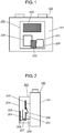
- FIG. 1 is a front view showing the structure of flow rate measurement device 100 according to the exemplary embodiment. Further, FIG. 2 is a side view showing the structure of flow rate measurement device 100.
- Flow rate measurement device 100 measures a measurement target which is one of, for example, gas, tap water, electricity and the like.
- Flow rate measurement device 100 is provided with wireless communication device 200 on its front side.
- Metal housing 101 is formed to have a substantially rectangular parallelepiped-shape (including a rectangular parallelepiped-shape), and is made of an electrically conductive material.
- the electrically conductive material may be, for example, metal selected from aluminum, stainless steel and the like, or electrically conductive resin.
- Wireless communication device 200 is formed by resin case 201.
- Resin case 201 houses meter controller board 202, radio frequency (RF) circuit board 203, long-distance radio radiating conductor 204, short-distance radio radiating conductor 205, inter-board connection cable 206, long-distance radio supporter 207, short-distance radio supporter 208, and RF circuit board connection cable 209.
- RF radio frequency
- Resin case 201 is disposed on the front wall of metal housing 101, and is made of a non-electrically conductive material.
- the non-electrically conductive material may be, for example, resin having an electrically insulating characteristic, which is selected from polypropylene, acrylonitrile-butadiene-styrene (ABS) and the like.
- Resin case 201 is formed into a rectangular parallelepiped-shape in which a front-rear thickness dimension is smaller than a top-bottom dimension and a right-left dimension.
- Meter controller board 202 includes an integrated circuit in which a program is installed.
- the integrated circuit includes a signal generating circuit that generates signals to be transmitted, based on any detected signals.
- the flow rate of a measurement target selected from gas, tap water and the like is acquired based on the detected value.
- the present invention does not particularly limit a method for obtaining a measured value.
- the measurement target is gas
- any known method selected from the diaphragm scheme, the ultrasonic scheme and the like may be employed. It is just required that a program necessary for calculating the measurement value based on the employed measurement method is installed in the integrated circuit.
- RF circuit board 203 has a structure in which a long-distance radio transmission circuit, a long-distance radio reception circuit, a short-distance radio transmission circuit, a short-distance radio reception circuit, long-distance radio radiating conductor 204, short-distance radio radiating conductor 205, a matching circuit, and the integrated circuit are mounted on a board.
- the long-distance radio transmission circuit transmits data to a wireless master unit over wireless communication.
- the long-distance radio reception circuit processes data received from the master unit over wireless communication.
- the short-distance radio transmission circuit transmits data to a handheld terminal over near-distance wireless communication.
- the short-distance radio reception circuit processes data received from the handheld terminal by near-distance wireless communication.
- the matching circuit matches the long-distance radio transmission circuit, the long-distance radio reception circuit, the short-distance radio transmission circuit, and the short-distance radio reception circuit with one another.
- the integrated circuit is electrically connected to long-distance radio radiating conductor 204 and short-distance radio radiating conductor 205, and includes a power supply circuit that supplies high frequency signals to long-distance radio radiating conductor 204 and short-distance radio radiating conductor 205.
- RF circuit board 203 and meter controller board 202 are electrically connected to each other by inter-board connection cable 206. Further, RF circuit board 203 is electrically connected to long-distance radio radiating conductor 204 via long-distance radio supporter 207 that extends perpendicularly to the plane of the board. Further, RF circuit board 203 is electrically connected to short-distance radio radiating conductor 205 via short-distance radio supporter 208 that extends perpendicularly to the plane of the board.
- the integrated circuit on meter controller board 202 applies potential to long-distance radio radiating conductor 204 and short-distance radio radiating conductor 205 in accordance with the measured data, thereby causing high frequency signals representing the measured data to be generated.
- Long-distance radio radiating conductor 204 radiates high frequency signals modulated by the long-distance radio transmission circuit as radio waves, and receives radio waves (high frequency signals) from an external source and passes the radio waves to the long-distance radio reception circuit that demodulates the radio waves.
- Short-distance radio radiating conductor 205 radiates high frequency signals modulated by the short-distance radio transmission circuit as radio waves, and receives radio waves (high frequency signals) from an external source, and passes the radio waves to the short-distance radio reception circuit that demodulates the radio waves.
- Long-distance radio radiating conductor 204 is connected to RF circuit board 203 via long-distance radio supporter 207, and short-distance radio radiating conductor 205 is connected to RF circuit board 203 via short-distance radio supporter 208. Since long-distance radio supporter 207 is structured to be shorter than short-distance radio supporter 208, short-distance radio radiating conductor 205 is positioned on the front side (the position being distanced from RF circuit board 203, and near to the front surface of resin case 201) relative to long-distance radio radiating conductor 204.
- This structure allows long-distance radio radiating conductor 204 to be distanced from RF circuit board 203, and to keep an appropriate distance also from resin case 201 and metal housing 101. This suppresses any influence of metal objects in resin case 201 and metal housing 101 on communication.
- short-distance radio radiating conductor 205 is positioned near the front surface of resin case 201, short-distance radio radiating conductor 205 can establish excellent communication with the handheld terminal within a several centimeter range.
- Long-distance radio radiating conductor 204 has the structure of a folded dipole antenna.
- Short-distance radio radiating conductor 205 has the structure of a loop antenna.
- RF circuit board 203 is electrically connected to metal housing 101 corresponding to ground, via RF circuit board connection cable 209.
- the portion where metal housing 101 and RF circuit board 203 are electrically connected to each other by RF circuit board connection cable 209 and the portion where long-distance radio supporter 207 is connected can be positioned with a minimum distance from each other. This enables full use of metal housing 101 as the antenna ground, and the effect of improving the antenna characteristic can be fully exhibited.
- wireless communication device 200 mounted on flow rate measurement device 100, namely, a long-distance wireless communication circuit that transmits data such as measured values to a wireless master unit, and a near-distance wireless communication circuit that communicates necessary information with a handheld terminal.
- wireless communication device 200 to the long-distance wireless communication and to the near-distance wireless communication.
- One problem is that, while the space for mounting the long-distance wireless communication circuit and the near-distance wireless communication circuit is limited, the board on which the near-distance wireless communication circuit is mounted tends to occupy the space by a greater proportion.
- an antenna In the near-distance wireless communication, an antenna should be loop-shaped and the loop area must be greater as much as possible, so that greater induced electromotive force occurs. Further, this antenna needs to be equipped with a high frequency matching circuit required for matching and a connector for connecting to the main board via a wired signal line. Hence, the board on which the near-distance wireless communication circuit is mounted increases in size by the area of the matching circuit and the area required for mounting the connector. Accordingly, a reduction in the installation area of the long-distance radio antenna is inevitable.
- Another problem is that, while the space for mounting the long-distance wireless communication circuit and the near-distance wireless communication circuit is limited, the board on which the long-distance wireless communication circuit is mounted and the board on which the near-distance wireless communication circuit is mounted cannot be easily integrated into one board.
- the communication performance becomes poor when the board on which the long-distance wireless communication circuit is mounted, or metal-made flow rate measurement device 100 exists nearby. Accordingly, the antenna needs to be disposed with a maximum possible distance from flow rate measurement device 100 and the board on which long-distance wireless communication circuit is mounted (RF circuit board 203).
- the board on which the long-distance wireless communication circuit is mounted is provided at a position near the flow rate measurement device.
- the long-distance wireless communication antenna stands perpendicularly to the board, and is folded toward the inner side of the case of the wireless communication device where the board is housed.
- a near-distance communication antenna that is realized by NFC (Near Field Communication) and communicates within a several centimeter range is normally formed on the surface of the board.
- the near-distance communication antenna is formed on the surface of the board on which the long-distance wireless communication circuit is mounted and which is positioned near flow rate measurement device 100.
- the near-distance communication antenna is covered at the deep portion of the case of wireless communication device 200, and therefore the near-distance communication antenna and the handheld terminal cannot be brought in close proximity to each other by a distance of several centimeters.
- flow rate measurement device 100 when the intended use of flow rate measurement device 100 is one of a gas meter, a water meter, and an electricity meter, an increase in the size of the case of wireless communication device 200 is limited.
- ⁇ /4 of long-distance radio radiating conductor 204 is about 45 cm.
- resin case 201 measures about 10 cm ⁇ 20 cm.
- short-distance radio radiating conductor 205 establishes wireless communication within a several centimeter range using a frequency of 13.65 MHz based on, for example, NFC (Near Field Communication) standards.
- the short-distance radio circuit is usually in a non-conducting state, and the antenna needs to excite current to thereby generate induced electromotive force. Accordingly, the antenna needs to be great in size to some extent. Normally, the antenna should measure about 7 cm ⁇ 4 cm.
- Short-distance radio radiating conductor 205 is normally formed on the board.
- Short-distance radio radiating conductor 205 is normally formed on the board.
- short-distance radio radiating conductor 205 is implemented by a self-supported linear antenna.
- a board signal-dedicated connector that conventionally needs to be provided on the board can be dispensed with.
- mounting the antenna matching circuit on the main board also reduces the area by the area of the matching circuit.
- long-distance radio radiating conductor 204 and short-distance radio radiating conductor 205 are disposed by respective supporters at different heights with reference to RF circuit board 203. This allows the antenna elements of long-distance radio radiating conductor 204 and short-distance radio radiating conductor 205 each forming a loop shape to be disposed with a maximum loop area. Further, as compared to the case where the antenna is formed on the board, the antenna can be implemented at extremely low costs.
- linear antenna radiating conductors are employed as long-distance radio radiating conductor 204 and short-distance radio radiating conductor 205.
- each radiating conductor may be other plate-like conductor elements.
- Exemplary linear conductor elements include a loop antenna, a meander line antenna and the like.
- Long-distance radio radiating conductor 204 and long-distance radio supporter 207 may be structured independently of each other or may be integrated with each other. When long-distance radio radiating conductor 204 and long-distance radio supporter 207 are structured independently of each other, they may be made of an identical material or different materials. Similarly, short-distance radio radiating conductor 205 and short-distance radio supporter 208 may be structured independently of each other or may be integrated with each other. When short-distance radio radiating conductor 205 and short-distance radio supporter 208 are structured independently of each other, they may be made of an identical material or different materials.
- linear conductor elements are employed as long-distance radio radiating conductor 204 and short-distance radio radiating conductor 205.
- the radiating conductors may be structured with other conductor elements.
- a planar conductor element selected from a planar inverted-F antenna, a linear inverted-L antenna, a planar dipole antenna and the like may be employed as each of the radiating conductors.
- wireless communication device 200 is integrally mounted on flow rate measurement device 100, the present invention is not limited thereto.
- wireless communication device 200 may be structured independently of the flow rate measurement device including the metal housing made of an electrically conductive material, and may be mounted on the flow rate measurement device.
- flow rate measurement device 100 includes: metal housing 101 that is made of an electrically conductive material and houses a sensor that detects a flow rate of a measurement target; long-distance radio radiating conductor 204 that radiates high frequency signal waves for establishing long-distance communication; short-distance radio radiating conductor 205 that radiates high frequency signal waves for establishing short-distance communication; RF circuit board 203 that electrically connects to long-distance radio radiating conductor 204 and short-distance radio radiating conductor 205; resin case 201 that is disposed on metal housing 101 and houses long-distance radio radiating conductor 204, short-distance radio radiating conductor 205, and RF circuit board 203; long-distance radio supporter 207 that supports long-distance radio radiating conductor 204 and extends perpendicularly to RF circuit board 203; and short-distance radio supporter 208 that supports short-distance
- This structure makes it possible to secure both the near-distance wireless communication enabled distance and the communication distance of the long-distance radio antenna at low costs.
- Long-distance radio radiating conductor 204 is structured using a folded dipole antenna and substantially in parallel to RF circuit board 203.
- Short-distance radio radiating conductor 205 is structured using a self-supported linear antenna and substantially in parallel to RF circuit board 203.
- long-distance radio radiating conductor 204 is implemented by a folded dipole antenna, the high antenna gain characteristic is obtained, and the antenna can be implemented by a linear metal. This reduces costs in terms of material and manufacture, and also eliminates the necessity for separately providing a connector or a connection cable for connecting the antenna and the board to each other.
- short-distance radio radiating conductor 205 is implemented by a linear self-supported antenna, the distance between the handheld terminal and short-distance radio radiating conductor 205 can be shortened, and the antenna can be implemented by a linear metal. This reduces costs in terms of material and manufacture, and the antenna is self-supported. This also eliminates the necessity for separately providing a connector or a connection cable for connecting the antenna and the board to each other. Overall, high antenna performance can be obtained cost effectively.
- the distance between long-distance radio radiating conductor 204 supported by long-distance radio supporter 207 and RF circuit board 203 is shorter than the distance between short-distance radio radiating conductor 205 supported by short-distance radio supporter 208 and RF circuit board 203.
- long-distance radio radiating conductor 204 is disposed to be distanced from the front surface of resin case 201 to some extent.
- flow rate measurement device 100 such as a gas meter is installed in a housing box whose front door is made of metal so as not to mar the appearance of the house.
- the distance between the front door and long-distance radio radiating conductor 204 is shortened, reducing the communication performance of the long-distance wireless communication.
- Long-distance radio radiating conductor 204 and short-distance radio radiating conductor 205 need to be distanced from each other in order to prevent metal of the radiating conductors from influencing each other.
- the upper limit of the size of wireless communication device 200 limits the mounting space in which the distance is secured. Accordingly, long-distance radio radiating conductor 204 and short-distance radio radiating conductor 205 are installed three-dimensionally at different heights.
- the frequencies of the high frequency signal waves for establishing the long-distance communication may be in a 169 MHz band, and the frequencies of the high frequency signal waves for establishing the short-distance communication may be in a 13.65 MHz band.
- the antenna in order to obtain the best antenna characteristic at 169 MHz, the antenna needs to be a quarter-wavelength long, that is, the length thereof needs to be about 45 cm.
- An antenna set to have a length of quarter-wavelength long as much as possible using the technique of the present exemplary embodiment can exhibit the best antenna characteristic.
- the transmission output up to 500 mW as the antenna output can be attained using the 169 MHz band.
- the long-distance radio propagation distance can be maximized.
- This structure also allows the short-distance communication antenna to be disposed as close as possible to the inner surface of the case of the wireless communication device. Accordingly, communication within a distance of several centimeters at the 13.6 MHz band can be realized.
- wireless communication device 200 includes: long-distance radio radiating conductor 204 that radiates high frequency signal waves for establishing long-distance communication; short-distance radio radiating conductor 205 that radiates high frequency signal waves for establishing short-distance communication; RF circuit board 203 that electrically connects to long-distance radio radiating conductor 204 and short-distance radio radiating conductor 205; resin case 201 that houses long-distance radio radiating conductor 204, short-distance radio radiating conductor 205, and RF circuit board 203; long-distance radio supporter 207 that supports long-distance radio radiating conductor 204 and extends perpendicularly to RF circuit board 203; and short-distance radio supporter 208 that supports short-distance radio radiating conductor 205 and extends perpendicularly to RF circuit board 203.
- This structure makes it possible to secure both the near-distance wireless communication enabled distance and the communication distance of the long-distance radio antenna at low costs.
- the present invention exhibits the advantageous effect of supporting the near-distance wireless communication and the long-distance wireless communication despite a limited mounting space.
- the present invention is useful as a flow rate measurement device that measures the flow rate of a measurement target, a wireless communication device connected to the flow rate measurement device and the like.
Landscapes
- Physics & Mathematics (AREA)
- Fluid Mechanics (AREA)
- General Physics & Mathematics (AREA)
- Measuring Volume Flow (AREA)
- Arrangements For Transmission Of Measured Signals (AREA)
- Details Of Flowmeters (AREA)
- Variable-Direction Aerials And Aerial Arrays (AREA)
- Support Of Aerials (AREA)
Applications Claiming Priority (2)
| Application Number | Priority Date | Filing Date | Title |
|---|---|---|---|
| JP2014026147 | 2014-02-14 | ||
| PCT/JP2015/000512 WO2015122157A1 (ja) | 2014-02-14 | 2015-02-05 | 流量計測装置および無線通信装置 |
Publications (3)
| Publication Number | Publication Date |
|---|---|
| EP3106842A1 EP3106842A1 (en) | 2016-12-21 |
| EP3106842A4 EP3106842A4 (en) | 2017-03-15 |
| EP3106842B1 true EP3106842B1 (en) | 2020-05-13 |
Family
ID=53799909
Family Applications (1)
| Application Number | Title | Priority Date | Filing Date |
|---|---|---|---|
| EP15749036.8A Active EP3106842B1 (en) | 2014-02-14 | 2015-02-05 | Flow rate measurement device and wireless communication device |
Country Status (4)
| Country | Link |
|---|---|
| EP (1) | EP3106842B1 (es) |
| JP (1) | JP6439147B2 (es) |
| ES (1) | ES2811089T3 (es) |
| WO (1) | WO2015122157A1 (es) |
Families Citing this family (6)
| Publication number | Priority date | Publication date | Assignee | Title |
|---|---|---|---|---|
| CN106781530A (zh) * | 2016-12-02 | 2017-05-31 | 杭州维昕科技有限公司 | 一种车位检测装置 |
| JP6870982B2 (ja) * | 2016-12-26 | 2021-05-12 | 東光東芝メーターシステムズ株式会社 | 電力量計用通信装置 |
| US10194220B2 (en) * | 2017-01-05 | 2019-01-29 | Pulse Finland Oy | Antenna apparatus that utilizes a utility line and methods of manufacturing and use |
| JP2020153666A (ja) * | 2019-03-18 | 2020-09-24 | アズビル金門株式会社 | ガスメータ |
| CN116710735A (zh) * | 2021-01-19 | 2023-09-05 | Vega格里沙贝两合公司 | 用于选择传感器无线电模块特征的装置和方法 |
| WO2023284925A1 (en) * | 2021-07-16 | 2023-01-19 | Kamstrup A/S | A flow meter unit |
Family Cites Families (10)
| Publication number | Priority date | Publication date | Assignee | Title |
|---|---|---|---|---|
| US6686886B2 (en) * | 2001-05-29 | 2004-02-03 | International Business Machines Corporation | Integrated antenna for laptop applications |
| US6448932B1 (en) * | 2001-09-04 | 2002-09-10 | Centurion Wireless Technologies, Inc. | Dual feed internal antenna |
| US6650294B2 (en) * | 2001-11-26 | 2003-11-18 | Telefonaktiebolaget Lm Ericsson (Publ) | Compact broadband antenna |
| JP4129369B2 (ja) * | 2002-04-30 | 2008-08-06 | 株式会社エリート | Rfidタグを利用した流量計の検針方法及び検針システム |
| EP1733453A1 (en) * | 2004-03-19 | 2006-12-20 | Kamstrup A/S | Consumption meter with integrated dual band antenna |
| US7889528B2 (en) * | 2006-11-29 | 2011-02-15 | Semiconductor Energy Laroratory Co., Ltd. | Rectifier circuit, power supply circuit, and semiconductor device |
| US7612725B2 (en) * | 2007-06-21 | 2009-11-03 | Apple Inc. | Antennas for handheld electronic devices with conductive bezels |
| US9160056B2 (en) * | 2010-04-01 | 2015-10-13 | Apple Inc. | Multiband antennas formed from bezel bands with gaps |
| EP2833476B1 (en) * | 2012-03-29 | 2019-09-11 | Panasonic Corporation | Flow volume measuring apparatus |
| JP6311993B2 (ja) * | 2012-07-18 | 2018-04-18 | パナソニックIpマネジメント株式会社 | 無線装置 |
-
2015
- 2015-02-05 EP EP15749036.8A patent/EP3106842B1/en active Active
- 2015-02-05 JP JP2015562726A patent/JP6439147B2/ja active Active
- 2015-02-05 WO PCT/JP2015/000512 patent/WO2015122157A1/ja active Application Filing
- 2015-02-05 ES ES15749036T patent/ES2811089T3/es active Active
Non-Patent Citations (1)
| Title |
|---|
| None * |
Also Published As
| Publication number | Publication date |
|---|---|
| ES2811089T3 (es) | 2021-03-10 |
| EP3106842A1 (en) | 2016-12-21 |
| JP6439147B2 (ja) | 2018-12-19 |
| JPWO2015122157A1 (ja) | 2017-03-30 |
| EP3106842A4 (en) | 2017-03-15 |
| WO2015122157A1 (ja) | 2015-08-20 |
Similar Documents
| Publication | Publication Date | Title |
|---|---|---|
| EP3106842B1 (en) | Flow rate measurement device and wireless communication device | |
| US7202825B2 (en) | Wireless communication device with integrated battery/antenna system | |
| EP2876821B1 (en) | Wireless device | |
| EP2645480B1 (en) | Wireless device | |
| KR20080042662A (ko) | Rfid 태그 판독 시스템 및 rfid 태그 판독 방법 | |
| EP3509160B1 (en) | Wireless communication device | |
| JP2010035124A (ja) | アンテナ装置 | |
| US9748651B2 (en) | Compound coupling to re-radiating antenna solution | |
| US20160204501A1 (en) | Closely coupled re-radiator compound loop antenna structure | |
| EP2833476B1 (en) | Flow volume measuring apparatus | |
| EP2863474A1 (en) | Wireless device | |
| JP5304790B2 (ja) | 無線装置とそれを備えた計測装置 | |
| EP3579335B1 (en) | Wireless communication device | |
| US20130043315A1 (en) | RFID tag with open-cavity antenna structure | |
| Kim et al. | RFID tag antenna mountable on metallic plates | |
| US10193228B2 (en) | Antenna for near field sensing and far field transceiving | |
| EP3024091A1 (en) | Wireless apparatus | |
| EP4304013A1 (en) | Non-powered element | |
| TW201302554A (zh) | 一種應用於塑膠棧板之rfid uhf標籤用平面迴路天線 | |
| JP4684152B2 (ja) | 磁界ループアンテナ | |
| WO2015175724A1 (en) | Compound coupling to re-radiating antenna solution | |
| JP2015026367A (ja) | 流量計測装置および流量計測装置に利用される無線装置 | |
| WO2016138480A1 (en) | Closely coupled re-radiator compound loop antenna structure | |
| JP2005109883A (ja) | 無線端末装置とこれを用いたデータ収集システム |
Legal Events
| Date | Code | Title | Description |
|---|---|---|---|
| PUAI | Public reference made under article 153(3) epc to a published international application that has entered the european phase |
Free format text: ORIGINAL CODE: 0009012 |
|
| STAA | Information on the status of an ep patent application or granted ep patent |
Free format text: STATUS: REQUEST FOR EXAMINATION WAS MADE |
|
| 17P | Request for examination filed |
Effective date: 20160808 |
|
| AK | Designated contracting states |
Kind code of ref document: A1 Designated state(s): AL AT BE BG CH CY CZ DE DK EE ES FI FR GB GR HR HU IE IS IT LI LT LU LV MC MK MT NL NO PL PT RO RS SE SI SK SM TR |
|
| AX | Request for extension of the european patent |
Extension state: BA ME |
|
| A4 | Supplementary search report drawn up and despatched |
Effective date: 20170214 |
|
| RIC1 | Information provided on ipc code assigned before grant |
Ipc: G01F 1/00 20060101AFI20170208BHEP Ipc: H01Q 21/30 20060101ALI20170208BHEP Ipc: G08C 17/02 20060101ALI20170208BHEP Ipc: H01Q 1/22 20060101ALI20170208BHEP Ipc: H01Q 1/24 20060101ALI20170208BHEP Ipc: H01Q 21/28 20060101ALI20170208BHEP Ipc: H01Q 7/00 20060101ALI20170208BHEP Ipc: G01F 15/06 20060101ALI20170208BHEP Ipc: H01Q 9/04 20060101ALI20170208BHEP Ipc: G08C 15/00 20060101ALI20170208BHEP |
|
| DAX | Request for extension of the european patent (deleted) | ||
| GRAP | Despatch of communication of intention to grant a patent |
Free format text: ORIGINAL CODE: EPIDOSNIGR1 |
|
| STAA | Information on the status of an ep patent application or granted ep patent |
Free format text: STATUS: GRANT OF PATENT IS INTENDED |
|
| INTG | Intention to grant announced |
Effective date: 20191206 |
|
| GRAS | Grant fee paid |
Free format text: ORIGINAL CODE: EPIDOSNIGR3 |
|
| GRAA | (expected) grant |
Free format text: ORIGINAL CODE: 0009210 |
|
| STAA | Information on the status of an ep patent application or granted ep patent |
Free format text: STATUS: THE PATENT HAS BEEN GRANTED |
|
| AK | Designated contracting states |
Kind code of ref document: B1 Designated state(s): AL AT BE BG CH CY CZ DE DK EE ES FI FR GB GR HR HU IE IS IT LI LT LU LV MC MK MT NL NO PL PT RO RS SE SI SK SM TR |
|
| REG | Reference to a national code |
Ref country code: GB Ref legal event code: FG4D |
|
| REG | Reference to a national code |
Ref country code: CH Ref legal event code: EP |
|
| REG | Reference to a national code |
Ref country code: DE Ref legal event code: R096 Ref document number: 602015052751 Country of ref document: DE |
|
| REG | Reference to a national code |
Ref country code: AT Ref legal event code: REF Ref document number: 1270882 Country of ref document: AT Kind code of ref document: T Effective date: 20200615 |
|
| REG | Reference to a national code |
Ref country code: LT Ref legal event code: MG4D |
|
| REG | Reference to a national code |
Ref country code: NL Ref legal event code: MP Effective date: 20200513 |
|
| PG25 | Lapsed in a contracting state [announced via postgrant information from national office to epo] |
Ref country code: NO Free format text: LAPSE BECAUSE OF FAILURE TO SUBMIT A TRANSLATION OF THE DESCRIPTION OR TO PAY THE FEE WITHIN THE PRESCRIBED TIME-LIMIT Effective date: 20200813 Ref country code: SE Free format text: LAPSE BECAUSE OF FAILURE TO SUBMIT A TRANSLATION OF THE DESCRIPTION OR TO PAY THE FEE WITHIN THE PRESCRIBED TIME-LIMIT Effective date: 20200513 Ref country code: GR Free format text: LAPSE BECAUSE OF FAILURE TO SUBMIT A TRANSLATION OF THE DESCRIPTION OR TO PAY THE FEE WITHIN THE PRESCRIBED TIME-LIMIT Effective date: 20200814 Ref country code: IS Free format text: LAPSE BECAUSE OF FAILURE TO SUBMIT A TRANSLATION OF THE DESCRIPTION OR TO PAY THE FEE WITHIN THE PRESCRIBED TIME-LIMIT Effective date: 20200913 Ref country code: FI Free format text: LAPSE BECAUSE OF FAILURE TO SUBMIT A TRANSLATION OF THE DESCRIPTION OR TO PAY THE FEE WITHIN THE PRESCRIBED TIME-LIMIT Effective date: 20200513 Ref country code: PT Free format text: LAPSE BECAUSE OF FAILURE TO SUBMIT A TRANSLATION OF THE DESCRIPTION OR TO PAY THE FEE WITHIN THE PRESCRIBED TIME-LIMIT Effective date: 20200914 Ref country code: LT Free format text: LAPSE BECAUSE OF FAILURE TO SUBMIT A TRANSLATION OF THE DESCRIPTION OR TO PAY THE FEE WITHIN THE PRESCRIBED TIME-LIMIT Effective date: 20200513 |
|
| PG25 | Lapsed in a contracting state [announced via postgrant information from national office to epo] |
Ref country code: LV Free format text: LAPSE BECAUSE OF FAILURE TO SUBMIT A TRANSLATION OF THE DESCRIPTION OR TO PAY THE FEE WITHIN THE PRESCRIBED TIME-LIMIT Effective date: 20200513 Ref country code: HR Free format text: LAPSE BECAUSE OF FAILURE TO SUBMIT A TRANSLATION OF THE DESCRIPTION OR TO PAY THE FEE WITHIN THE PRESCRIBED TIME-LIMIT Effective date: 20200513 Ref country code: RS Free format text: LAPSE BECAUSE OF FAILURE TO SUBMIT A TRANSLATION OF THE DESCRIPTION OR TO PAY THE FEE WITHIN THE PRESCRIBED TIME-LIMIT Effective date: 20200513 Ref country code: BG Free format text: LAPSE BECAUSE OF FAILURE TO SUBMIT A TRANSLATION OF THE DESCRIPTION OR TO PAY THE FEE WITHIN THE PRESCRIBED TIME-LIMIT Effective date: 20200813 |
|
| REG | Reference to a national code |
Ref country code: AT Ref legal event code: MK05 Ref document number: 1270882 Country of ref document: AT Kind code of ref document: T Effective date: 20200513 |
|
| PG25 | Lapsed in a contracting state [announced via postgrant information from national office to epo] |
Ref country code: AL Free format text: LAPSE BECAUSE OF FAILURE TO SUBMIT A TRANSLATION OF THE DESCRIPTION OR TO PAY THE FEE WITHIN THE PRESCRIBED TIME-LIMIT Effective date: 20200513 Ref country code: NL Free format text: LAPSE BECAUSE OF FAILURE TO SUBMIT A TRANSLATION OF THE DESCRIPTION OR TO PAY THE FEE WITHIN THE PRESCRIBED TIME-LIMIT Effective date: 20200513 |
|
| PG25 | Lapsed in a contracting state [announced via postgrant information from national office to epo] |
Ref country code: AT Free format text: LAPSE BECAUSE OF FAILURE TO SUBMIT A TRANSLATION OF THE DESCRIPTION OR TO PAY THE FEE WITHIN THE PRESCRIBED TIME-LIMIT Effective date: 20200513 Ref country code: DK Free format text: LAPSE BECAUSE OF FAILURE TO SUBMIT A TRANSLATION OF THE DESCRIPTION OR TO PAY THE FEE WITHIN THE PRESCRIBED TIME-LIMIT Effective date: 20200513 Ref country code: RO Free format text: LAPSE BECAUSE OF FAILURE TO SUBMIT A TRANSLATION OF THE DESCRIPTION OR TO PAY THE FEE WITHIN THE PRESCRIBED TIME-LIMIT Effective date: 20200513 Ref country code: CZ Free format text: LAPSE BECAUSE OF FAILURE TO SUBMIT A TRANSLATION OF THE DESCRIPTION OR TO PAY THE FEE WITHIN THE PRESCRIBED TIME-LIMIT Effective date: 20200513 Ref country code: SM Free format text: LAPSE BECAUSE OF FAILURE TO SUBMIT A TRANSLATION OF THE DESCRIPTION OR TO PAY THE FEE WITHIN THE PRESCRIBED TIME-LIMIT Effective date: 20200513 Ref country code: EE Free format text: LAPSE BECAUSE OF FAILURE TO SUBMIT A TRANSLATION OF THE DESCRIPTION OR TO PAY THE FEE WITHIN THE PRESCRIBED TIME-LIMIT Effective date: 20200513 |
|
| REG | Reference to a national code |
Ref country code: DE Ref legal event code: R097 Ref document number: 602015052751 Country of ref document: DE |
|
| PG25 | Lapsed in a contracting state [announced via postgrant information from national office to epo] |
Ref country code: PL Free format text: LAPSE BECAUSE OF FAILURE TO SUBMIT A TRANSLATION OF THE DESCRIPTION OR TO PAY THE FEE WITHIN THE PRESCRIBED TIME-LIMIT Effective date: 20200513 Ref country code: SK Free format text: LAPSE BECAUSE OF FAILURE TO SUBMIT A TRANSLATION OF THE DESCRIPTION OR TO PAY THE FEE WITHIN THE PRESCRIBED TIME-LIMIT Effective date: 20200513 |
|
| REG | Reference to a national code |
Ref country code: ES Ref legal event code: FG2A Ref document number: 2811089 Country of ref document: ES Kind code of ref document: T3 Effective date: 20210310 |
|
| PLBE | No opposition filed within time limit |
Free format text: ORIGINAL CODE: 0009261 |
|
| STAA | Information on the status of an ep patent application or granted ep patent |
Free format text: STATUS: NO OPPOSITION FILED WITHIN TIME LIMIT |
|
| 26N | No opposition filed |
Effective date: 20210216 |
|
| PG25 | Lapsed in a contracting state [announced via postgrant information from national office to epo] |
Ref country code: SI Free format text: LAPSE BECAUSE OF FAILURE TO SUBMIT A TRANSLATION OF THE DESCRIPTION OR TO PAY THE FEE WITHIN THE PRESCRIBED TIME-LIMIT Effective date: 20200513 |
|
| PG25 | Lapsed in a contracting state [announced via postgrant information from national office to epo] |
Ref country code: MC Free format text: LAPSE BECAUSE OF FAILURE TO SUBMIT A TRANSLATION OF THE DESCRIPTION OR TO PAY THE FEE WITHIN THE PRESCRIBED TIME-LIMIT Effective date: 20200513 |
|
| REG | Reference to a national code |
Ref country code: BE Ref legal event code: MM Effective date: 20210228 |
|
| PG25 | Lapsed in a contracting state [announced via postgrant information from national office to epo] |
Ref country code: CH Free format text: LAPSE BECAUSE OF NON-PAYMENT OF DUE FEES Effective date: 20210228 Ref country code: LI Free format text: LAPSE BECAUSE OF NON-PAYMENT OF DUE FEES Effective date: 20210228 Ref country code: LU Free format text: LAPSE BECAUSE OF NON-PAYMENT OF DUE FEES Effective date: 20210205 |
|
| PG25 | Lapsed in a contracting state [announced via postgrant information from national office to epo] |
Ref country code: IE Free format text: LAPSE BECAUSE OF NON-PAYMENT OF DUE FEES Effective date: 20210205 |
|
| PG25 | Lapsed in a contracting state [announced via postgrant information from national office to epo] |
Ref country code: BE Free format text: LAPSE BECAUSE OF NON-PAYMENT OF DUE FEES Effective date: 20210228 |
|
| PGFP | Annual fee paid to national office [announced via postgrant information from national office to epo] |
Ref country code: FR Payment date: 20220421 Year of fee payment: 9 |
|
| PG25 | Lapsed in a contracting state [announced via postgrant information from national office to epo] |
Ref country code: HU Free format text: LAPSE BECAUSE OF FAILURE TO SUBMIT A TRANSLATION OF THE DESCRIPTION OR TO PAY THE FEE WITHIN THE PRESCRIBED TIME-LIMIT; INVALID AB INITIO Effective date: 20150205 |
|
| PGFP | Annual fee paid to national office [announced via postgrant information from national office to epo] |
Ref country code: IT Payment date: 20230223 Year of fee payment: 9 |
|
| PG25 | Lapsed in a contracting state [announced via postgrant information from national office to epo] |
Ref country code: CY Free format text: LAPSE BECAUSE OF FAILURE TO SUBMIT A TRANSLATION OF THE DESCRIPTION OR TO PAY THE FEE WITHIN THE PRESCRIBED TIME-LIMIT Effective date: 20200513 |
|
| PGFP | Annual fee paid to national office [announced via postgrant information from national office to epo] |
Ref country code: ES Payment date: 20240326 Year of fee payment: 10 |
|
| PG25 | Lapsed in a contracting state [announced via postgrant information from national office to epo] |
Ref country code: MK Free format text: LAPSE BECAUSE OF FAILURE TO SUBMIT A TRANSLATION OF THE DESCRIPTION OR TO PAY THE FEE WITHIN THE PRESCRIBED TIME-LIMIT Effective date: 20200513 |
|
| PGFP | Annual fee paid to national office [announced via postgrant information from national office to epo] |
Ref country code: DE Payment date: 20240219 Year of fee payment: 10 Ref country code: GB Payment date: 20240219 Year of fee payment: 10 |