EP3106839A1 - Sensor system for laminated structures - Google Patents
Sensor system for laminated structures Download PDFInfo
- Publication number
- EP3106839A1 EP3106839A1 EP16173039.5A EP16173039A EP3106839A1 EP 3106839 A1 EP3106839 A1 EP 3106839A1 EP 16173039 A EP16173039 A EP 16173039A EP 3106839 A1 EP3106839 A1 EP 3106839A1
- Authority
- EP
- European Patent Office
- Prior art keywords
- sensor
- laminated structure
- sensing line
- stress
- temperature
- Prior art date
- Legal status (The legal status is an assumption and is not a legal conclusion. Google has not performed a legal analysis and makes no representation as to the accuracy of the status listed.)
- Granted
Links
Images



Classifications
-
- G—PHYSICS
- G01—MEASURING; TESTING
- G01L—MEASURING FORCE, STRESS, TORQUE, WORK, MECHANICAL POWER, MECHANICAL EFFICIENCY, OR FLUID PRESSURE
- G01L1/00—Measuring force or stress, in general
- G01L1/24—Measuring force or stress, in general by measuring variations of optical properties of material when it is stressed, e.g. by photoelastic stress analysis using infrared, visible light, ultraviolet
- G01L1/241—Measuring force or stress, in general by measuring variations of optical properties of material when it is stressed, e.g. by photoelastic stress analysis using infrared, visible light, ultraviolet by photoelastic stress analysis
-
- G—PHYSICS
- G01—MEASURING; TESTING
- G01D—MEASURING NOT SPECIALLY ADAPTED FOR A SPECIFIC VARIABLE; ARRANGEMENTS FOR MEASURING TWO OR MORE VARIABLES NOT COVERED IN A SINGLE OTHER SUBCLASS; TARIFF METERING APPARATUS; MEASURING OR TESTING NOT OTHERWISE PROVIDED FOR
- G01D5/00—Mechanical means for transferring the output of a sensing member; Means for converting the output of a sensing member to another variable where the form or nature of the sensing member does not constrain the means for converting; Transducers not specially adapted for a specific variable
- G01D5/26—Mechanical means for transferring the output of a sensing member; Means for converting the output of a sensing member to another variable where the form or nature of the sensing member does not constrain the means for converting; Transducers not specially adapted for a specific variable characterised by optical transfer means, i.e. using infrared, visible, or ultraviolet light
- G01D5/32—Mechanical means for transferring the output of a sensing member; Means for converting the output of a sensing member to another variable where the form or nature of the sensing member does not constrain the means for converting; Transducers not specially adapted for a specific variable characterised by optical transfer means, i.e. using infrared, visible, or ultraviolet light with attenuation or whole or partial obturation of beams of light
- G01D5/34—Mechanical means for transferring the output of a sensing member; Means for converting the output of a sensing member to another variable where the form or nature of the sensing member does not constrain the means for converting; Transducers not specially adapted for a specific variable characterised by optical transfer means, i.e. using infrared, visible, or ultraviolet light with attenuation or whole or partial obturation of beams of light the beams of light being detected by photocells
- G01D5/353—Mechanical means for transferring the output of a sensing member; Means for converting the output of a sensing member to another variable where the form or nature of the sensing member does not constrain the means for converting; Transducers not specially adapted for a specific variable characterised by optical transfer means, i.e. using infrared, visible, or ultraviolet light with attenuation or whole or partial obturation of beams of light the beams of light being detected by photocells influencing the transmission properties of an optical fibre
-
- G—PHYSICS
- G01—MEASURING; TESTING
- G01K—MEASURING TEMPERATURE; MEASURING QUANTITY OF HEAT; THERMALLY-SENSITIVE ELEMENTS NOT OTHERWISE PROVIDED FOR
- G01K11/00—Measuring temperature based upon physical or chemical changes not covered by groups G01K3/00, G01K5/00, G01K7/00 or G01K9/00
- G01K11/32—Measuring temperature based upon physical or chemical changes not covered by groups G01K3/00, G01K5/00, G01K7/00 or G01K9/00 using changes in transmittance, scattering or luminescence in optical fibres
-
- G—PHYSICS
- G01—MEASURING; TESTING
- G01K—MEASURING TEMPERATURE; MEASURING QUANTITY OF HEAT; THERMALLY-SENSITIVE ELEMENTS NOT OTHERWISE PROVIDED FOR
- G01K5/00—Measuring temperature based on the expansion or contraction of a material
- G01K5/48—Measuring temperature based on the expansion or contraction of a material the material being a solid
- G01K5/56—Measuring temperature based on the expansion or contraction of a material the material being a solid constrained so that expansion or contraction causes a deformation of the solid
- G01K5/58—Measuring temperature based on the expansion or contraction of a material the material being a solid constrained so that expansion or contraction causes a deformation of the solid the solid body being constrained at more than one point, e.g. rod, plate, diaphragm
-
- G—PHYSICS
- G01—MEASURING; TESTING
- G01K—MEASURING TEMPERATURE; MEASURING QUANTITY OF HEAT; THERMALLY-SENSITIVE ELEMENTS NOT OTHERWISE PROVIDED FOR
- G01K7/00—Measuring temperature based on the use of electric or magnetic elements directly sensitive to heat ; Power supply therefor, e.g. using thermoelectric elements
-
- G—PHYSICS
- G01—MEASURING; TESTING
- G01L—MEASURING FORCE, STRESS, TORQUE, WORK, MECHANICAL POWER, MECHANICAL EFFICIENCY, OR FLUID PRESSURE
- G01L1/00—Measuring force or stress, in general
- G01L1/18—Measuring force or stress, in general using properties of piezo-resistive materials, i.e. materials of which the ohmic resistance varies according to changes in magnitude or direction of force applied to the material
-
- G—PHYSICS
- G01—MEASURING; TESTING
- G01L—MEASURING FORCE, STRESS, TORQUE, WORK, MECHANICAL POWER, MECHANICAL EFFICIENCY, OR FLUID PRESSURE
- G01L1/00—Measuring force or stress, in general
- G01L1/24—Measuring force or stress, in general by measuring variations of optical properties of material when it is stressed, e.g. by photoelastic stress analysis using infrared, visible light, ultraviolet
- G01L1/242—Measuring force or stress, in general by measuring variations of optical properties of material when it is stressed, e.g. by photoelastic stress analysis using infrared, visible light, ultraviolet the material being an optical fibre
-
- G—PHYSICS
- G01—MEASURING; TESTING
- G01L—MEASURING FORCE, STRESS, TORQUE, WORK, MECHANICAL POWER, MECHANICAL EFFICIENCY, OR FLUID PRESSURE
- G01L1/00—Measuring force or stress, in general
- G01L1/24—Measuring force or stress, in general by measuring variations of optical properties of material when it is stressed, e.g. by photoelastic stress analysis using infrared, visible light, ultraviolet
- G01L1/242—Measuring force or stress, in general by measuring variations of optical properties of material when it is stressed, e.g. by photoelastic stress analysis using infrared, visible light, ultraviolet the material being an optical fibre
- G01L1/246—Measuring force or stress, in general by measuring variations of optical properties of material when it is stressed, e.g. by photoelastic stress analysis using infrared, visible light, ultraviolet the material being an optical fibre using integrated gratings, e.g. Bragg gratings
-
- G—PHYSICS
- G01—MEASURING; TESTING
- G01L—MEASURING FORCE, STRESS, TORQUE, WORK, MECHANICAL POWER, MECHANICAL EFFICIENCY, OR FLUID PRESSURE
- G01L1/00—Measuring force or stress, in general
- G01L1/25—Measuring force or stress, in general using wave or particle radiation, e.g. X-rays, microwaves, neutrons
-
- G—PHYSICS
- G01—MEASURING; TESTING
- G01B—MEASURING LENGTH, THICKNESS OR SIMILAR LINEAR DIMENSIONS; MEASURING ANGLES; MEASURING AREAS; MEASURING IRREGULARITIES OF SURFACES OR CONTOURS
- G01B11/00—Measuring arrangements characterised by the use of optical techniques
- G01B11/002—Measuring arrangements characterised by the use of optical techniques for measuring two or more coordinates
-
- G—PHYSICS
- G01—MEASURING; TESTING
- G01B—MEASURING LENGTH, THICKNESS OR SIMILAR LINEAR DIMENSIONS; MEASURING ANGLES; MEASURING AREAS; MEASURING IRREGULARITIES OF SURFACES OR CONTOURS
- G01B11/00—Measuring arrangements characterised by the use of optical techniques
- G01B11/16—Measuring arrangements characterised by the use of optical techniques for measuring the deformation in a solid, e.g. optical strain gauge
-
- G—PHYSICS
- G01—MEASURING; TESTING
- G01D—MEASURING NOT SPECIALLY ADAPTED FOR A SPECIFIC VARIABLE; ARRANGEMENTS FOR MEASURING TWO OR MORE VARIABLES NOT COVERED IN A SINGLE OTHER SUBCLASS; TARIFF METERING APPARATUS; MEASURING OR TESTING NOT OTHERWISE PROVIDED FOR
- G01D5/00—Mechanical means for transferring the output of a sensing member; Means for converting the output of a sensing member to another variable where the form or nature of the sensing member does not constrain the means for converting; Transducers not specially adapted for a specific variable
- G01D5/26—Mechanical means for transferring the output of a sensing member; Means for converting the output of a sensing member to another variable where the form or nature of the sensing member does not constrain the means for converting; Transducers not specially adapted for a specific variable characterised by optical transfer means, i.e. using infrared, visible, or ultraviolet light
- G01D5/268—Mechanical means for transferring the output of a sensing member; Means for converting the output of a sensing member to another variable where the form or nature of the sensing member does not constrain the means for converting; Transducers not specially adapted for a specific variable characterised by optical transfer means, i.e. using infrared, visible, or ultraviolet light using optical fibres
-
- G—PHYSICS
- G01—MEASURING; TESTING
- G01D—MEASURING NOT SPECIALLY ADAPTED FOR A SPECIFIC VARIABLE; ARRANGEMENTS FOR MEASURING TWO OR MORE VARIABLES NOT COVERED IN A SINGLE OTHER SUBCLASS; TARIFF METERING APPARATUS; MEASURING OR TESTING NOT OTHERWISE PROVIDED FOR
- G01D5/00—Mechanical means for transferring the output of a sensing member; Means for converting the output of a sensing member to another variable where the form or nature of the sensing member does not constrain the means for converting; Transducers not specially adapted for a specific variable
- G01D5/26—Mechanical means for transferring the output of a sensing member; Means for converting the output of a sensing member to another variable where the form or nature of the sensing member does not constrain the means for converting; Transducers not specially adapted for a specific variable characterised by optical transfer means, i.e. using infrared, visible, or ultraviolet light
- G01D5/28—Mechanical means for transferring the output of a sensing member; Means for converting the output of a sensing member to another variable where the form or nature of the sensing member does not constrain the means for converting; Transducers not specially adapted for a specific variable characterised by optical transfer means, i.e. using infrared, visible, or ultraviolet light with deflection of beams of light, e.g. for direct optical indication
- G01D5/30—Mechanical means for transferring the output of a sensing member; Means for converting the output of a sensing member to another variable where the form or nature of the sensing member does not constrain the means for converting; Transducers not specially adapted for a specific variable characterised by optical transfer means, i.e. using infrared, visible, or ultraviolet light with deflection of beams of light, e.g. for direct optical indication the beams of light being detected by photocells
-
- G—PHYSICS
- G01—MEASURING; TESTING
- G01D—MEASURING NOT SPECIALLY ADAPTED FOR A SPECIFIC VARIABLE; ARRANGEMENTS FOR MEASURING TWO OR MORE VARIABLES NOT COVERED IN A SINGLE OTHER SUBCLASS; TARIFF METERING APPARATUS; MEASURING OR TESTING NOT OTHERWISE PROVIDED FOR
- G01D5/00—Mechanical means for transferring the output of a sensing member; Means for converting the output of a sensing member to another variable where the form or nature of the sensing member does not constrain the means for converting; Transducers not specially adapted for a specific variable
- G01D5/26—Mechanical means for transferring the output of a sensing member; Means for converting the output of a sensing member to another variable where the form or nature of the sensing member does not constrain the means for converting; Transducers not specially adapted for a specific variable characterised by optical transfer means, i.e. using infrared, visible, or ultraviolet light
- G01D5/32—Mechanical means for transferring the output of a sensing member; Means for converting the output of a sensing member to another variable where the form or nature of the sensing member does not constrain the means for converting; Transducers not specially adapted for a specific variable characterised by optical transfer means, i.e. using infrared, visible, or ultraviolet light with attenuation or whole or partial obturation of beams of light
- G01D5/34—Mechanical means for transferring the output of a sensing member; Means for converting the output of a sensing member to another variable where the form or nature of the sensing member does not constrain the means for converting; Transducers not specially adapted for a specific variable characterised by optical transfer means, i.e. using infrared, visible, or ultraviolet light with attenuation or whole or partial obturation of beams of light the beams of light being detected by photocells
- G01D5/353—Mechanical means for transferring the output of a sensing member; Means for converting the output of a sensing member to another variable where the form or nature of the sensing member does not constrain the means for converting; Transducers not specially adapted for a specific variable characterised by optical transfer means, i.e. using infrared, visible, or ultraviolet light with attenuation or whole or partial obturation of beams of light the beams of light being detected by photocells influencing the transmission properties of an optical fibre
- G01D5/35306—Mechanical means for transferring the output of a sensing member; Means for converting the output of a sensing member to another variable where the form or nature of the sensing member does not constrain the means for converting; Transducers not specially adapted for a specific variable characterised by optical transfer means, i.e. using infrared, visible, or ultraviolet light with attenuation or whole or partial obturation of beams of light the beams of light being detected by photocells influencing the transmission properties of an optical fibre using an interferometer arrangement
- G01D5/35309—Mechanical means for transferring the output of a sensing member; Means for converting the output of a sensing member to another variable where the form or nature of the sensing member does not constrain the means for converting; Transducers not specially adapted for a specific variable characterised by optical transfer means, i.e. using infrared, visible, or ultraviolet light with attenuation or whole or partial obturation of beams of light the beams of light being detected by photocells influencing the transmission properties of an optical fibre using an interferometer arrangement using multiple waves interferometer
- G01D5/35316—Mechanical means for transferring the output of a sensing member; Means for converting the output of a sensing member to another variable where the form or nature of the sensing member does not constrain the means for converting; Transducers not specially adapted for a specific variable characterised by optical transfer means, i.e. using infrared, visible, or ultraviolet light with attenuation or whole or partial obturation of beams of light the beams of light being detected by photocells influencing the transmission properties of an optical fibre using an interferometer arrangement using multiple waves interferometer using a Bragg gratings
-
- G—PHYSICS
- G01—MEASURING; TESTING
- G01D—MEASURING NOT SPECIALLY ADAPTED FOR A SPECIFIC VARIABLE; ARRANGEMENTS FOR MEASURING TWO OR MORE VARIABLES NOT COVERED IN A SINGLE OTHER SUBCLASS; TARIFF METERING APPARATUS; MEASURING OR TESTING NOT OTHERWISE PROVIDED FOR
- G01D5/00—Mechanical means for transferring the output of a sensing member; Means for converting the output of a sensing member to another variable where the form or nature of the sensing member does not constrain the means for converting; Transducers not specially adapted for a specific variable
- G01D5/26—Mechanical means for transferring the output of a sensing member; Means for converting the output of a sensing member to another variable where the form or nature of the sensing member does not constrain the means for converting; Transducers not specially adapted for a specific variable characterised by optical transfer means, i.e. using infrared, visible, or ultraviolet light
- G01D5/32—Mechanical means for transferring the output of a sensing member; Means for converting the output of a sensing member to another variable where the form or nature of the sensing member does not constrain the means for converting; Transducers not specially adapted for a specific variable characterised by optical transfer means, i.e. using infrared, visible, or ultraviolet light with attenuation or whole or partial obturation of beams of light
- G01D5/34—Mechanical means for transferring the output of a sensing member; Means for converting the output of a sensing member to another variable where the form or nature of the sensing member does not constrain the means for converting; Transducers not specially adapted for a specific variable characterised by optical transfer means, i.e. using infrared, visible, or ultraviolet light with attenuation or whole or partial obturation of beams of light the beams of light being detected by photocells
- G01D5/353—Mechanical means for transferring the output of a sensing member; Means for converting the output of a sensing member to another variable where the form or nature of the sensing member does not constrain the means for converting; Transducers not specially adapted for a specific variable characterised by optical transfer means, i.e. using infrared, visible, or ultraviolet light with attenuation or whole or partial obturation of beams of light the beams of light being detected by photocells influencing the transmission properties of an optical fibre
- G01D5/3537—Optical fibre sensor using a particular arrangement of the optical fibre itself
-
- G—PHYSICS
- G01—MEASURING; TESTING
- G01K—MEASURING TEMPERATURE; MEASURING QUANTITY OF HEAT; THERMALLY-SENSITIVE ELEMENTS NOT OTHERWISE PROVIDED FOR
- G01K1/00—Details of thermometers not specially adapted for particular types of thermometer
- G01K1/08—Protective devices, e.g. casings
-
- G—PHYSICS
- G01—MEASURING; TESTING
- G01K—MEASURING TEMPERATURE; MEASURING QUANTITY OF HEAT; THERMALLY-SENSITIVE ELEMENTS NOT OTHERWISE PROVIDED FOR
- G01K11/00—Measuring temperature based upon physical or chemical changes not covered by groups G01K3/00, G01K5/00, G01K7/00 or G01K9/00
- G01K11/32—Measuring temperature based upon physical or chemical changes not covered by groups G01K3/00, G01K5/00, G01K7/00 or G01K9/00 using changes in transmittance, scattering or luminescence in optical fibres
- G01K11/3206—Measuring temperature based upon physical or chemical changes not covered by groups G01K3/00, G01K5/00, G01K7/00 or G01K9/00 using changes in transmittance, scattering or luminescence in optical fibres at discrete locations in the fibre, e.g. using Bragg scattering
-
- G—PHYSICS
- G01—MEASURING; TESTING
- G01L—MEASURING FORCE, STRESS, TORQUE, WORK, MECHANICAL POWER, MECHANICAL EFFICIENCY, OR FLUID PRESSURE
- G01L1/00—Measuring force or stress, in general
- G01L1/24—Measuring force or stress, in general by measuring variations of optical properties of material when it is stressed, e.g. by photoelastic stress analysis using infrared, visible light, ultraviolet
- G01L1/247—Measuring force or stress, in general by measuring variations of optical properties of material when it is stressed, e.g. by photoelastic stress analysis using infrared, visible light, ultraviolet using distributed sensing elements, e.g. microcapsules
-
- G—PHYSICS
- G02—OPTICS
- G02B—OPTICAL ELEMENTS, SYSTEMS OR APPARATUS
- G02B6/00—Light guides; Structural details of arrangements comprising light guides and other optical elements, e.g. couplings
- G02B6/24—Coupling light guides
- G02B6/36—Mechanical coupling means
- G02B6/3608—Fibre wiring boards, i.e. where fibres are embedded or attached in a pattern on or to a substrate, e.g. flexible sheets
Definitions
- the present disclosure relates to laminated structures and systems for determining environmental effects on laminated structures, such as forces and temperatures, and more particularly to a sensor system for laminated structures.
- Laminated structures are becoming more widely used in making articles, such as aircraft and other vehicles or equipment where light weight but strong material are beneficial.
- Laminated structures in such applications may be subjected to various environmental conditions, such as extreme forces and loading that may be applied in various ways and temperature changes that may vary over a wide range.
- Sensors for determining or measuring such environmental conditions are mounted on an exterior surface of laminated structures. Data from these external sensors may be analyzed to project or estimate the effects of the environmental conditions within the laminated structure but external sensors cannot provide direct monitoring of conditions within the interior of the laminated structure.
- a sensor system for a laminated structure may include a sensor assembly disposed between a first layer of the laminated structure and a second layer of the laminated structure.
- the second layer of the laminated structure is disposed on the first layer and the sensor assembly.
- the sensor assembly may include a first anchor member and a second anchor member spaced at a predetermined distance from the first anchor member.
- a sensor chamber is formed between the first anchor member and the second anchor member.
- the sensor assembly may also include a sensing line extending between the first anchor member and the second anchor member through the sensor chamber and through the first anchor member and the second anchor member.
- the sensing line may include a configuration within the sensor chamber for sensing one of stress forces within the laminated structure, temperature or temperature changes within the laminated structure.
- the sensor system may also include a first transport tube extending from the first anchor member opposite the sensor chamber and between the first layer of the laminated structure and the second layer of the laminated structure.
- the sensor system may additionally include a second transport tube extending from the second anchor member opposite the sensor chamber and between the first layer of the laminated structure and the second layer of the laminated structure.
- the sensing line also extends through the first transport tube and the second transport tube.
- a sensor for a laminated structure may include a first anchor member and a second anchor member spaced at a predetermined distance from the first anchor member.
- the sensor may also include a sensor chamber formed between the first anchor member and the second anchor member and a sensing line extending between the first anchor member and the second anchor member through the sensor chamber and through the anchor members.
- the sensing line may include a configuration within the sensor chamber for sensing one of stress forces within the laminated structure, temperature or temperature changes within the laminated structure.
- the sensor may also include a first transport tube extending from the first anchor member opposite the sensor chamber and between the first layer of the laminated structure and the second layer of the laminated structure.
- the sensor may also include a second transport tube extending from the second anchor member opposite the sensor chamber and between the first layer of the laminated structure and the second layer of the laminated structure.
- the sensing line also extends through the first transport tube and the second transport tube.
- the sensing line extends through the first transport tube and the second transport tube without any tension on the sensing line to prevent any stress on the sensing line within the first transport tube and the second transport in response to forces being applied to the laminated structure.
- a method of sensing at least one of stress and temperature within a laminated structure may include providing one or more pairs of sensor anchor members on a first layer of the laminated structure. Each pair of sensor anchor members may be spaced a predetermined distance apart to provide a sensor chamber between each pair of sensor anchor members. The method may also include providing a transport tube between each pair of sensor anchor members on the first layer of the laminated structure. The method may additionally include extending a sensing line through each transport tube and through each sensor chamber. The sensing line is extended through each transport tube without any tension on the sensing line within each transport tube to prevent any stress on the sensing line in the transport tubes in response to forces being applied to the laminated structure. The method may further include configuring each sensing line within each sensor chamber for sensing one of stress forces within the laminated structure, temperature or temperature changes within the laminated structure. The method may additionally include depositing a second layer of the laminated structure on the first layer.
- the senor or sensor assembly may include a stress sensor.
- the sensing line may be held within the sensor chamber by a first anchor member and a second anchor member at a preset tension to form the stress sensor, wherein a physical stress applied to the laminated structure causes a corresponding change to the preset tension of the sensing line within the sensor chamber.
- the sensor or sensor assembly may include a thermal sensor.
- the thermal sensor may include a thermally sensitive plate disposed within the sensor chamber and a selected portion of the sensing line is attached to the thermally sensitive plate to form the thermal sensor.
- the sensing line extends from the thermally sensitive plate respectively to a first anchor member and a second anchor member without any tension or a predetermined amount of slack. Changes in temperature in the sensor chamber cause the thermally sensitive plate to distort which causes stress in the sensing line corresponding to the temperature or changes in temperature.
- the sensing line may include one of an optical fiber and an electrically conductive wire. Either an optical signal or a radio frequency (RF) signal may be transmitted through the sensing line to measure or detect stress in the laminated structure, or temperature or temperature changes in the laminated structure.
- RF radio frequency
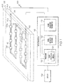
- FIG. 1 is a schematic diagram of an example of a sensor system 100 for monitoring internal conditions of a laminated structure 102 in accordance with an example.
- the laminated structure 102 may be part of a component of an aircraft, such as for example a portion of a wing, fuselage, bulkhead or other component of an aircraft or other vehicle.
- the laminated structure 102 may also be part of or a component of another structure including but not necessarily limited to a civil structure, such as a building or bridge, an electrical transformer, a motor, a composite structure, a storage tank, hull or other component of a ship or other structures.
- Laminated structures may include a plurality of layers of material that may be bonded together to form a structure that is typically stronger and lighter in weight than a single layer of material that would have to be thicker to provide the same strength or durability.
- the laminated structure 102 includes a first layer 104 and a second layer 106.
- the laminated structure 102 may include more than two layers.
- the second layer 106 is shown by broken or dashed lines to permit the sensor components or sensor assemblies 108 and transport tubes 110 for the sensing line 112 of the sensor system 100 to be shown.
- the transport tubes 110 extend between each of the sensor assemblies 108, and between each terminal sensor assembly 108a and an edge 114 of the laminated structure 102.
- Each of the sensor assemblies 108 may be configured to provide a stress sensor for sensing stress or strain forces, or a thermal sensor for sensing temperature or temperature changes.
- An example of a sensor assembly 108 configured to provide a stress sensor will be described with reference to FIG. 3 below.
- An example of a sensor assembly 108 configured to provide a thermal sensor will be described with reference to FIG. 4 .
- the sensor system 100 may include a plurality of sensor assemblies 108 distributed at predetermined locations in the laminated structure 102 between the first layer 104 of the laminated structure 102 and the second layer 106 of the laminated structure 102.
- each sensor assembly 108 or the sensing line 118 within each sensor assembly 108 may be configured to provide one of a stress sensor that senses stress forces within the laminated structure 102 or a thermal sensor that senses temperature or temperature changes within the laminated structure 102.
- the sensor system 100 may include a plurality of transport tubes 110.
- a transport tube 110 may extend between adjacent sensor assemblies 108.
- the plurality of sensor assemblies 108 are connected in series by the transport tubes 110.
- Another one of the transport tubes or an end transport tube 110a may extend from each end or terminal sensor assembly 108a of the series connected sensor assemblies 108 to an edge 114 of the laminated structure 102.
- the sensing line 112 extends loosely through the plurality of transport tubes 110 without any tension on the sensing line 112 within the transport tubes 110 so that any forces applied to the laminated structure 102 will not cause any stress (compression or tension) or strain on the sensing line 112 within the transport tubes 110.
- the sensing line 112 may be any conductive medium in which the conductivity of the sensing line 112 or medium may be modified based on a physical stress being applied to the sensing line 112 or conductive medium.
- the physical stress may be applied by external forces being applied to the laminated structure 102 or the result of temperature or temperature changes within the laminated structure 102 that cause modification of the conductivity of the sensing line 112 or conductive medium.
- the changes or modification of the conductivity may be determined or sensed by transmitting a signal or signals through the sensing line 112 or conductive medium.
- the stress, temperature, or temperature changes may be determined or calculated by detecting changes in one or more properties or parameters of the transmitted signal or signals, such as time, frequency and amplitude changes caused by the changes or modification of the conductivity of the sensing line 112.
- the sensing line 112 may be an optical fiber for transmitting optical signals.
- the sensing line 112 may be an electrically conductive wire for carrying electrical signals or radio frequency (RF) signals.
- sensing line 112 may be a resistive wire where a relevant portion of the resistive wire may have a characteristic resistivity based on the tension per unit length.
- RF radio frequency
- the actual stress (or temperature) measurement values are possible to determine quite accurately based on the selection of materials and the length of the sensing line portion under tension, but often it is the relative measurement values over time that may be more useful since these can indicate the presence of an emergent, degenerate condition that could damage or reduce the useful life of the instrumented structure 102.
- a detection device 116 may be operatively connected to the sensing line 112.
- the detection device 116 may be configured to detect or determine one or more of physical stress, temperature or temperature changes in each of the sensor assemblies 108 based on a signal or signals received from each of the plurality of sensor assemblies 108.
- the detection device 116 may include a signal generator or transmitter 118 operatively connected to one end or an input end 128 of the sensing line 112 to transmit a signal or signals through the sensing line 112.
- the detection device 116 may also include a signal detector or receiver 120 that may be operatively connected to another end or output end 130 of the sensing line 112 and configured to receive the signal or signals from the plurality of sensor assemblies 108.
- the detector device 116 may additionally include a processor 122 programmed with a location of each of the plurality of sensor assemblies 108 within the laminated structure 102.
- the processor 122 may include a signal processing module 124 that may be configured to determine one or more of a physical stress, a temperature or temperature changes at each of the sensor assemblies 108.
- the physical stress, temperature or temperature changes at each of the sensor assemblies 108 are based on changes to one or more properties or parameters of the transmitted signal or signals detected by each the plurality of sensor assemblies 108 caused by modification or changes to the conductivity of the sensing line 116 in the respective sensor assemblies 108.
- the one or more properties or parameters of the transmitted signal or signals that may be changed by modifications in the conductivity of the sensing line 112 may include the timing, frequency and amplitude of the signal or signals.
- any changes in conductivity within each of the sensor assemblies 108 may be detected from the signal or signals received by the signal detector or receiver 120.
- the corresponding physical stress, temperature or temperature changes may be determined or calculated by the signal processing module 124 from changes in the one or more properties or parameters of the transmitted signal or signals.
- a display 126 may be associated with the detection device 116, as shown in the exemplary example in FIG. 1 , or the display 126 may be incorporated as part of the detection device 116.
- the sensor assemblies 108 are configured to provide stress sensors, stress measurements within the laminated structure 102 from analysis of the signals from the sensor assemblies 108 may be presented on the display 126.
- the sensor assemblies 108 are configured to provide thermal sensors, temperature measurements or temperature change measurements within the laminated structure 102 from analysis of the signals from the sensor assemblies 108 may be presented on the display 126.
- some sensor assemblies 108 may be configured to provide stress sensors and other sensor assemblies 108 may be configured to provide thermal sensors.
- either stress measurements or temperature measurements within the laminated structure 102 may be presented on the display 126. Stress and temperature measurements or calculations may be presented over time to analyze different conditions within the laminated structure 102. For example, the temperature and stress measurements across an interior of the laminated structure may be plotted to determine hot or cold spots, weak stress points or other properties or characteristics of the laminated structure 102.
- the sensing line 112 may be an optical fiber.
- the signal generator or transmitter 118 may be an optical signal generator that transmits an optical signal through the sensing line 112 or optical fiber.
- the signal detector or receiver 120 may be an optical signal detector that measures one or more properties or parameters of the transmitted optical signal at the output 130 of the sensing line 112.
- the signal processing module 124 may determine a stress on the laminated structure 102 at a location of a stress sensor or temperature or temperature changes at a location of a thermal sensor based on measurement of one or more properties or parameters, such as amplitude, frequency, timing or a combination thereof, of the optical signal transmitted through the optical fiber and responsive to a change or modification of conductivity of the sensing line 112 of the sensor assembly 108.
- the sensing line 112 may an electrically conductive wire for transmitting electrical signals or radio frequency (RF) signals.
- the signals may be of any nature or characteristics that may permit monitoring and detection of any changes in time, frequency or amplitude or any combination of these properties or parameters of a transmitted signal that can correspond to a measurement of temperature or stress in the laminated structure 102.
- the signal generator or transmitter 118 may be an RF signal generator that transmits an RF signal through the electrically conductive wire or sensing line 112.
- the signal detector or receiver 120 may be an RF receiver that detects and monitors changes in time, frequency, amplitude or any combination thereof of the transmitted RF signal at the output 130 of the sensing line 112 or electrically conductive wire.
- the signal processing module 124 may determine a stress on the laminated structure 102 at a location of the stress sensor, or temperature or temperature change at a location of a thermal sensor based on changes or modification of the conductivity of the electrically conductive wire and measurement of one or more properties or parameters of the RF signal or signals transmitted through the electrically conductive wire resulting from the conductivity changes, such as changes in amplitude, timing and frequency of the signal or signals or any combination of these properties or parameters.
- FIG. 2 is a schematic diagram of an example of a sensor system 200 for monitoring internal conditions of a laminated structure 202 in accordance with another example.
- the laminated structure 202 may be similar to the laminated structure 102 in FIG. 1 and may include a plurality of layers of laminated material.
- the laminated structure 202 may include a first layer 204 and a second layer 206 of laminated material.
- the second layer 206 is shown by broken or dashed lines to permit the sensor components or sensor assemblies 208 and transport tubes 210 for the sensing lines 212 of the sensor system 200 to be shown.
- the transport tubes 210 extend between each of the sensor assemblies 208, and between each terminal sensor assembly 208a and an edge 213 of laminated structure 202.
- the sensor system 200 may be similar to the sensor system 100 in FIG. 1 . except that instead of having a single detection device similar to detection device 116, the sensor system 200 may include a signal generator or transmitter 214 that is operatively connected to the sensing line 212 at one end 216 of the sensing line 212 and a signal detector or receiver 218 that is operatively connected to the sensing line 212 at an opposite end 220.
- the exemplary sensor system 200 in FIG. 2 may be applicable in situations where the one end 216 of the sensing line 212 is at a considerable distance from the opposite end 220 of the sensing line 212 and a single detection device similar to detection device 116 in FIG.
- a detection device similar to detection device 116 in FIG. 1 may be operatively connected to each end 216 and 220 of the sensing line 212.
- Each detection device may operate similar to detection device 116 and may detect or determine physical stress, temperature or temperature changes in each of the sensor assemblies 208 based on whether the sensor assemblies 208 are configured as stress sensors or thermal sensors and the signals received from the of the sensor assemblies 208.
- the signal detector or receiver 218 may include a processor 222 or the processor may be a separate component.
- the processor 222 may include a signal processing module 224 that may be configured to determine one or more of a physical stress, a temperature or temperature changes for each of the sensor assemblies 208 based on whether each of the sensor assemblies 208 is configured to include a stress sensor or a thermal sensor and the signals received from each of the stress sensors or thermal sensors.
- a display 226 may be associated with the signal detector or receiver 218 to present analysis of the signals by the signal processing module 224 and present a representation of the stress measurements, temperature measurements or both within the laminated structure 202 based on the configuration of the sensor assemblies 208 and analysis of the signals from the sensor assemblies 208 by the signal processing module 224.
- Each of the sensor assemblies 208 may be configured to provide a stress sensor or a thermal sensor. As previously discussed, an example of a sensor assembly 208 configured to provide a stress sensor will be described with reference to FIG. 3 and an example of a sensor assembly 208 configured to provide a thermal sensor will be described with reference to FIG. 4 .
- the sensor system 200 may include a plurality of sensor assemblies 208 distributed at predetermined locations in the laminated structure 202 between the first layer 204 of the laminated structure 202 and the second layer 206 of the laminated structure 202.
- each sensor assembly 208 or the sensing line 212 within each sensor assembly 208 may be configured to provide one of a stress sensor that senses stress forces within the laminated structure 202 or a thermal sensor that senses temperature or temperature changes within the laminated structure 202.
- the signal generator or transmitter 214 may be configured to transmit a test signal or signals through the sensing line 212 and the signal detector or receiver 218 may receive signals from the plurality of sensor assemblies 208.
- the signal generator 214 may be connected to the signal detector 218 by a communications link 221.
- a synchronization signal may be transmitted by the signal generator 214 to the signal detector 218 over the communications link to establish timing and/or a frequency lock between transmission of the test signal or signals through the sensing line 212 for detection by the signal detector 218.
- the communications link 221 may be a wired or wireless communications link. Similar to that previously described with respect to system 100 in FIG.
- the synchronization signal along with a known location of each of the sensor assemblies 208 along the sensing line 212 within the laminated structure 202 allows any changes in conductivity within each of the sensor assemblies 208 to be detected from the signal or signals received by the signal detector or receiver 218 and the corresponding physical stress, temperature or temperature changes may be determined or calculated by the signal processing module 224.
- the sensing line 212 may be an optical fiber for transmitting optical signals.
- the optical signals may be of any nature or characteristics that may permit monitoring and detection of any changes in time, frequency or amplitude or any combination of these parameters or properties of a transmitted optical signal that can correspond to a measurement of temperature and/or stress in the laminated structure 202.
- the sensing line 212 may be an electrically conductive wire for carrying electrical signals or RF signals.
- the electrical or RF signals may be of any nature or characteristics that may permit monitoring and detection of any changes in time, frequency or amplitude or any combination of these parameters or properties of a transmitted signal that can correspond to a measurement of temperature and/or stress in the laminated structure 202.
- the sensing line 212 extends through the transport tubes 210 without any tension on the sensing lines 212 to prevent any stress or strain on the sensing line 212 within the transport tubes 210 in response to any forces being applied to the laminated structure 202.
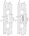
- FIG. 3 is a cross-sectional view of a laminated structure 300 including an example of a sensor assembly 302 configured to provide a stress sensor 304 of a sensor system in accordance with an example.
- the sensor assembly 302 may be used for each of the sensor assemblies 108 in FIG. 1 and 208 in FIG. 2 .
- stress sensor 304 cannot directly measure stress, but rather a stress load may be inferred based on the electrical and/or optical response of one or more stress sensors 304.
- the sensor assembly 302 may be disposed between a first layer 306 of the laminated structure 300 and a second layer 308 of the laminated structure 300.
- the second layer 308 of the laminated structure 300 may be disposed on the first layer 306.
- the sensor assembly 302 may include a first anchor member 310 and a second anchor member 312 spaced at a predetermined distance "D" from the first anchor member 310.
- a sensor chamber 314 is formed between the first anchor member 310 and the second anchor member 312.
- a sensing line 316 extends between the first anchor member 310 and the second anchor member 312 through the sensor chamber 314 and the sensing line 316 extends through the first anchor member 310 and the second anchor member 312.
- the sensing line 316 includes a configuration within the sensor chamber 314 for sensing one of stress forces within the laminated structure 300.
- stress sensor 304 cannot directly measure stress, but rather a stress load may be inferred based on the electrical and/or optical response of one or more stress sensors 304.
- the stress sensor 304 measures the stretching or compression of the sensing line 316 between the anchor members 310 and 312.
- the sensing line 316 may be held within the sensor chamber 314 by the first anchor member 310 and the second anchor member 312 at a preset tension to form the stress sensor 304.
- a physical stress applied to the laminated structure 300 causes a corresponding change to the preset tension of the sensing line 316 within the sensor chamber 314.
- a detection device such as detection device 116 may be operatively connected to the sensing line 316.
- the detection device may be configured to detect the corresponding change to the preset tension of the sensing line 316 within the sensor chamber 314 caused by movement of the first anchor member 310 and the second anchor member 314 in response to one more forces being applied to the laminated structure 300.
- the sensing line 316 may be either an optical fiber or an electrically conductive wire.
- the detection device such as detection device 116, may analyze an optical signal or signals or RF signal or signals transmitted through the sensing line 316 to determine a stress on the laminated structure 300 at a location of the stress sensor 304.
- the signals may be of any nature or characteristics that may permit monitoring and detection of any changes in time, frequency or amplitude or any combination of these parameters or properties of a transmitted signal caused by modification of the conductivity of the sensing line 316.
- the changes in these parameters or properties caused by modification of the conductivity of the sensing line 316 correspond to or can be translated to a measurement of temperature or stress in the laminated structure 102 similar to that previously described.
- the sensor assembly 302 may also include a first transport tube 318 and a second transport tube 320.
- the first transport tube 318 may extend from the first anchor member 310 opposite the sensor chamber 314 and between the first layer 306 and the second layer 308 of the laminated structure 300.
- the second transport tube 320 may extend from the second anchor member 312 opposite the sensor chamber 314 and between the first layer 306 and the second layer 308 of the laminated structure 300.
- the sensing line 316 extends through the first transport tube 318 and the second transport tube 320 and may connect to adjacent sensor assemblies similar to that shown and described with reference to FIG. 1 and FIG. 2 .
- the sensing line 316 extends through the first transport tube 318 and the second transport tube 320 without any tension on the sensing line 316 to prevent any stress on the sensing line 316 within the transport tubes 316 and 320 in response to forces being applied to the laminated structure 300.
- FIG. 4 is a cross-sectional view of a laminated structure 400 including an example of a sensor assembly 402 configured to provide a thermal sensor 404 of a sensor system in accordance with an example.
- the sensor assembly 402 may be used for each of the sensor assemblies 108 in FIG. 1 and 208 in FIG. 2 .
- the sensor assembly 402 may be disposed between a first layer 406 and a second layer 408 of the laminated structure 400.
- the second layer 408 of the laminated structure 400 may be disposed on the first layer 406.
- the sensor assembly 402 may include a first anchor member 410 and a second anchor member 412 spaced at a predetermined distance "D" from the first anchor member 410.
- a sensor chamber 414 is formed between the first anchor member 410 and the second anchor member 412.
- a sensing line 416 extends between the first anchor member 410 and the second anchor member 412 through the sensor chamber 414 and the sensing line 416 extends through the first anchor member 410 and the second anchor member 412.
- the sensing line 416 includes a configuration within the sensor chamber 414 for sensing temperature or temperature changes within the laminated structure 300.
- the sensor assembly 402 may also include a thermally sensitive plate 418 disposed within the sensor chamber 414.
- the thermally sensitive plate 418 has known physical properties that allow the plate 418 to expand and contract in a defined manor for detection and measure of temperature and/or temperature changes.
- the thermally sensitive plate 418 may be attached to one of the first layer 406 or the second layer 408 of the laminated structure 400 within the sensor chamber 414.
- a selected portion 420 of the sensing line 416 may be attached to the thermally sensitive plate 418 to form the thermal sensor 404.
- the sensing line 416 extends from the thermally sensitive plate 418 respectively to the first anchor member 410 and the second anchor member 412 without any tension or a predetermined amount of slack in the sensing line 416. Changes in temperature in the sensor chamber 414 may cause the thermally sensitive plate 418 to distort or expand and contract which causes stress in the sensing line 416 corresponding to the temperature or changes in temperature.
- a detection device such as detection device 116 may be operatively connected to the sensing line 416.
- the detection device may be configured to detect the corresponding stress in the sensing line 416 within the sensor chamber 414 caused by the distortion of the thermally sensitive plate 418 in response to the temperature or temperature changes in the sensor chamber 414.
- the sensing line 416 may be either an optical fiber or an electrically conductive wire.
- the detection device such as detection device 116, may analyze an optical signal or signals or RF signal or signals transmitted through the sensing line 416 to determine a temperature or temperature changes within laminated structure 400 at a location of the thermal sensor 404.
- the sensor assembly 402 may also include a first transport tube 422 and a second transport tube 424.
- the first transport tube 422 may extend from the first anchor member 410 opposite the sensor chamber 414 and between the first layer 406 and the second layer 408 of the laminated structure 400.
- the second transport tube 424 may extend from the second anchor member 412 opposite the sensor chamber 414 and between the first layer 406 and the second layer 408 of the laminated structure 400.
- the sensing line 416 extends through the first transport tube 422 and the second transport tube 424 and may connect to adjacent sensor assemblies similar to that shown and described with reference to FIG. 1 and FIG. 2 .
- the sensing line 416 extends through the transport tubes 422 and 424 without any tension to prevent any stress on the sensing line 416 in response to any forces being applied to the laminated structure 400.
- FIG. 5 is a cross-sectional view of an example of a multi-layer laminated structure 500 and a plurality of sensor assemblies 502 disposed in different layers of the multi-layer laminated structure 500 in accordance with an example.
- the exemplary multi-layered laminated structure 500 is shown as including a first layer 504, a second layer 506 and a third layer 508, although, the laminated structure 500 may have any number of layers.
- the sensor assemblies 502 shown in the exemplary example in FIG. 5 are configured as stress sensors similar to the exemplary stress sensor 304 in FIG. 3 . In another example, the sensor assemblies 502 could also be configures as thermal sensors similar to the exemplary sensor assemblies 402 shown and described with reference to FIG. 4 .
- a group of sensor assemblies in a laminated structure may be configured to provide stress sensors and another group of sensor assemblies in the laminated structure may be configured as thermal sensors.
- the sensor assemblies 502 are disposed between the different layers 504-508 to provide sensing or monitoring of stresses and/or temperature within the different layers 504-508.
- the sensor assemblies 502 may be offset from one another or spaced at predetermined intervals for optimum coverage of the laminated structure 500.
- FIG. 6 is a flow chart of an example of a method 600 for providing a sensor system in a laminated structure in accordance with an example of the present disclosure.
- the sensor system may be similar to sensor system 100 in FIG. 1 or 200 in FIG. 2 .
- one or more sensor assemblies may be provided on a first layer of material of a laminated structure.
- Each sensor assembly may include a pair of sensor anchor members.
- the sensor anchor members in each sensor assembly may be spaced a predetermined distance apart to define a sensor chamber between each pair of sensor anchor members.
- a transport tube for carrying a sensing line may be provided between each of the sensor assemblies.
- the sensor assemblies may be connected in series by the transport tubes and the sensing line.
- Another transport tube may connect the sensor assembly at each end of the series connected sensor assemblies and an edge of the laminated structure and provide access to each end the sensing line at a respective edge of the laminated structure.
- the sensing line may be extended through the transport tubes between each of the sensor assemblies and through the sensor anchor members of each sensor assembly.
- the sensing line may be either an optical fiber or an electrical conductive wire.
- the sensing line may extend through the transport tubes without any tension to prevent any strain on the sensing line in response to forces being applied to the laminated structure.
- the sensing line may be configured in each sensor assembly as a stress sensor for sensing stress forces or a thermal sensor for sensing temperature or temperature changes.
- a physical stress sensor may be formed by drawing and retaining the sensing line within each sensor chamber at a preset tension. Any physical stress applied to the laminated structure may cause movement of the sensor anchor members and a corresponding change in the preset tension of the sensing line within the sensor chamber.
- a thermal sensor may be formed in a sensor assembly by disposing a thermally sensitive plate within the sensor chamber.
- the sensing line may be attached to the thermally sensitive plate.
- the ends of the sensing line are attached between the plate and the sensor anchor members without any tension or a predetermined amount of slack in the sensing line. Any temperature changes in the sensor chamber may cause distortion of the thermally sensitive plate which causes a change in stress of the sensing line corresponding to the temperature or temperature changes.
- a second layer of material of the laminated structure may be deposited on the first layer of material and over the sensor system.
- a signal or signals may be transmitted through the sensing line.
- the transmitted signal or signals may be an optical signal or signals if the sensing line is an optical fiber.
- the transmitted signal or signals may be an RF signal or signals if the sensing line is an electrically conductive wire.
- changes or modification of conductivity of the sensing line may cause changes in the transmitted signal or signals that may be detected.
- One or more properties of the transmitted signal or signals, such as changes in amplitude, may be detected to determine at least one of a level of stress or temperature or temperature changes at a location of each sensor assembly based on the detected properties of the signals or analysis of the received signals.
- results of the stress and or temperature measurements and analysis may be presented at the corresponding locations of the sensors or sensor assemblies in the laminated structure.
- the results may be presented to a user viewing a display (126/226).
- each block in the flowchart or block diagrams may represent a module, segment, or portion of instructions, which comprises one or more executable instructions for implementing the specified logical function(s).
- the functions noted in the block may occur out of the order noted in the figures.
- two blocks shown in succession may, in fact, be executed substantially concurrently, or the blocks may sometimes be executed in the reverse order, depending upon the functionality involved.
Landscapes
- Physics & Mathematics (AREA)
- General Physics & Mathematics (AREA)
- Health & Medical Sciences (AREA)
- Toxicology (AREA)
- Testing Or Calibration Of Command Recording Devices (AREA)
- Force Measurement Appropriate To Specific Purposes (AREA)
- Measurement Of Force In General (AREA)
- Measuring Temperature Or Quantity Of Heat (AREA)
Abstract
Description
- The present disclosure relates to laminated structures and systems for determining environmental effects on laminated structures, such as forces and temperatures, and more particularly to a sensor system for laminated structures.
- Laminated structures are becoming more widely used in making articles, such as aircraft and other vehicles or equipment where light weight but strong material are beneficial. Laminated structures in such applications may be subjected to various environmental conditions, such as extreme forces and loading that may be applied in various ways and temperature changes that may vary over a wide range. Sensors for determining or measuring such environmental conditions are mounted on an exterior surface of laminated structures. Data from these external sensors may be analyzed to project or estimate the effects of the environmental conditions within the laminated structure but external sensors cannot provide direct monitoring of conditions within the interior of the laminated structure.
- In accordance with an example, a sensor system for a laminated structure may include a sensor assembly disposed between a first layer of the laminated structure and a second layer of the laminated structure. The second layer of the laminated structure is disposed on the first layer and the sensor assembly. The sensor assembly may include a first anchor member and a second anchor member spaced at a predetermined distance from the first anchor member. A sensor chamber is formed between the first anchor member and the second anchor member. The sensor assembly may also include a sensing line extending between the first anchor member and the second anchor member through the sensor chamber and through the first anchor member and the second anchor member. The sensing line may include a configuration within the sensor chamber for sensing one of stress forces within the laminated structure, temperature or temperature changes within the laminated structure. The sensor system may also include a first transport tube extending from the first anchor member opposite the sensor chamber and between the first layer of the laminated structure and the second layer of the laminated structure. The sensor system may additionally include a second transport tube extending from the second anchor member opposite the sensor chamber and between the first layer of the laminated structure and the second layer of the laminated structure. The sensing line also extends through the first transport tube and the second transport tube.
- In accordance with another example, a sensor for a laminated structure may include a first anchor member and a second anchor member spaced at a predetermined distance from the first anchor member. The sensor may also include a sensor chamber formed between the first anchor member and the second anchor member and a sensing line extending between the first anchor member and the second anchor member through the sensor chamber and through the anchor members. The sensing line may include a configuration within the sensor chamber for sensing one of stress forces within the laminated structure, temperature or temperature changes within the laminated structure. The sensor may also include a first transport tube extending from the first anchor member opposite the sensor chamber and between the first layer of the laminated structure and the second layer of the laminated structure. The sensor may also include a second transport tube extending from the second anchor member opposite the sensor chamber and between the first layer of the laminated structure and the second layer of the laminated structure. The sensing line also extends through the first transport tube and the second transport tube. The sensing line extends through the first transport tube and the second transport tube without any tension on the sensing line to prevent any stress on the sensing line within the first transport tube and the second transport in response to forces being applied to the laminated structure.
- In accordance with a further example, a method of sensing at least one of stress and temperature within a laminated structure may include providing one or more pairs of sensor anchor members on a first layer of the laminated structure. Each pair of sensor anchor members may be spaced a predetermined distance apart to provide a sensor chamber between each pair of sensor anchor members. The method may also include providing a transport tube between each pair of sensor anchor members on the first layer of the laminated structure. The method may additionally include extending a sensing line through each transport tube and through each sensor chamber. The sensing line is extended through each transport tube without any tension on the sensing line within each transport tube to prevent any stress on the sensing line in the transport tubes in response to forces being applied to the laminated structure. The method may further include configuring each sensing line within each sensor chamber for sensing one of stress forces within the laminated structure, temperature or temperature changes within the laminated structure. The method may additionally include depositing a second layer of the laminated structure on the first layer.
- In accordance with another example or any of the previous examples, the sensor or sensor assembly may include a stress sensor. The sensing line may be held within the sensor chamber by a first anchor member and a second anchor member at a preset tension to form the stress sensor, wherein a physical stress applied to the laminated structure causes a corresponding change to the preset tension of the sensing line within the sensor chamber.
- In accordance with another example or any of the previous examples, the sensor or sensor assembly may include a thermal sensor. The thermal sensor may include a thermally sensitive plate disposed within the sensor chamber and a selected portion of the sensing line is attached to the thermally sensitive plate to form the thermal sensor. The sensing line extends from the thermally sensitive plate respectively to a first anchor member and a second anchor member without any tension or a predetermined amount of slack. Changes in temperature in the sensor chamber cause the thermally sensitive plate to distort which causes stress in the sensing line corresponding to the temperature or changes in temperature.
- In accordance with another example or any of the previous examples, the sensing line may include one of an optical fiber and an electrically conductive wire. Either an optical signal or a radio frequency (RF) signal may be transmitted through the sensing line to measure or detect stress in the laminated structure, or temperature or temperature changes in the laminated structure.
- The following detailed description of examples refers to the accompanying drawings, which illustrate specific examples of the disclosure. Other examples having different structures and operations do not depart from the scope of the present disclosure.
-
FIG. 1 is a schematic diagram of an example of a sensor system for monitoring internal conditions of a laminated structure in accordance with an example. -
FIG. 2 is a schematic diagram of an example of a sensor system for monitoring internal conditions of a laminated structure in accordance with another example. -
FIG. 3 is a cross-sectional view of a laminated structure including an example of a sensor assembly configured to provide a stress sensor of a sensor system in accordance with an example. -
FIG. 4 is a cross-sectional view of a laminated structure including an example of a sensor assembly configured to provide a thermal sensor of a sensor system in accordance with an example. -
FIG. 5 is a cross-sectional view of an example of a multi-layer laminated structure and a plurality of sensor assemblies disposed in different layers of the multi-layer laminated structure in accordance with an example. -
FIG. 6 is a flow chart of an example of a method for providing a sensor system in a laminated structure in accordance with an example of the present disclosure. - The following detailed description of examples refers to the accompanying drawings, which illustrate specific examples of the disclosure. Other examples having different structures and operations do not depart from the scope of the present disclosure. Like reference numerals may refer to the same element or component in the different drawings.
- Certain terminology is used herein for convenience only and is not to be taken as a limitation on the examples described. For example, words such as "proximal", "distal", "top", "bottom", "upper," "lower," "left," "right," "horizontal," "vertical," "upward," and "downward", etc., merely describe the configuration shown in the figures or relative positions used with reference to the orientation of the figures being described. Because components of examples can be positioned in a number of different orientations, the directional terminology is used for purposes of illustration and is in no way limiting. It is to be understood that other examples may be utilized and structural or logical changes may be made without departing from the scope of the present invention. The following detailed description, therefore, is not to be taken in a limiting sense, and the scope of the present invention is defined by the appended claims.
-
FIG. 1 is a schematic diagram of an example of asensor system 100 for monitoring internal conditions of a laminatedstructure 102 in accordance with an example. The laminatedstructure 102 may be part of a component of an aircraft, such as for example a portion of a wing, fuselage, bulkhead or other component of an aircraft or other vehicle. The laminatedstructure 102 may also be part of or a component of another structure including but not necessarily limited to a civil structure, such as a building or bridge, an electrical transformer, a motor, a composite structure, a storage tank, hull or other component of a ship or other structures. Laminated structures may include a plurality of layers of material that may be bonded together to form a structure that is typically stronger and lighter in weight than a single layer of material that would have to be thicker to provide the same strength or durability. In the example illustrated inFIG. 1 , the laminatedstructure 102 includes afirst layer 104 and asecond layer 106. In other examples, the laminatedstructure 102 may include more than two layers. Thesecond layer 106 is shown by broken or dashed lines to permit the sensor components orsensor assemblies 108 andtransport tubes 110 for thesensing line 112 of thesensor system 100 to be shown. Thetransport tubes 110 extend between each of thesensor assemblies 108, and between eachterminal sensor assembly 108a and anedge 114 of the laminatedstructure 102. Each of thesensor assemblies 108 may be configured to provide a stress sensor for sensing stress or strain forces, or a thermal sensor for sensing temperature or temperature changes. An example of asensor assembly 108 configured to provide a stress sensor will be described with reference toFIG. 3 below. An example of asensor assembly 108 configured to provide a thermal sensor will be described with reference toFIG. 4 . - The
sensor system 100 may include a plurality ofsensor assemblies 108 distributed at predetermined locations in thelaminated structure 102 between thefirst layer 104 of thelaminated structure 102 and thesecond layer 106 of thelaminated structure 102. As previously discussed, eachsensor assembly 108 or thesensing line 118 within eachsensor assembly 108 may be configured to provide one of a stress sensor that senses stress forces within thelaminated structure 102 or a thermal sensor that senses temperature or temperature changes within thelaminated structure 102. - The
sensor system 100 may include a plurality oftransport tubes 110. Atransport tube 110 may extend betweenadjacent sensor assemblies 108. In theexemplary sensor system 100 shown inFIG. 1 , the plurality ofsensor assemblies 108 are connected in series by thetransport tubes 110. Another one of the transport tubes or anend transport tube 110a may extend from each end orterminal sensor assembly 108a of the series connectedsensor assemblies 108 to anedge 114 of thelaminated structure 102. Thesensing line 112 extends loosely through the plurality oftransport tubes 110 without any tension on thesensing line 112 within thetransport tubes 110 so that any forces applied to thelaminated structure 102 will not cause any stress (compression or tension) or strain on thesensing line 112 within thetransport tubes 110. - The
sensing line 112 may be any conductive medium in which the conductivity of thesensing line 112 or medium may be modified based on a physical stress being applied to thesensing line 112 or conductive medium. As described herein the physical stress may be applied by external forces being applied to thelaminated structure 102 or the result of temperature or temperature changes within thelaminated structure 102 that cause modification of the conductivity of thesensing line 112 or conductive medium. The changes or modification of the conductivity may be determined or sensed by transmitting a signal or signals through thesensing line 112 or conductive medium. The stress, temperature, or temperature changes may be determined or calculated by detecting changes in one or more properties or parameters of the transmitted signal or signals, such as time, frequency and amplitude changes caused by the changes or modification of the conductivity of thesensing line 112. - In accordance with an example, the
sensing line 112 may be an optical fiber for transmitting optical signals. In another example, thesensing line 112 may be an electrically conductive wire for carrying electrical signals or radio frequency (RF) signals. In yet another example, sensingline 112 may be a resistive wire where a relevant portion of the resistive wire may have a characteristic resistivity based on the tension per unit length. Various materials and methods of measurement are known to those of skill in the art. The actual stress (or temperature) measurement values are possible to determine quite accurately based on the selection of materials and the length of the sensing line portion under tension, but often it is the relative measurement values over time that may be more useful since these can indicate the presence of an emergent, degenerate condition that could damage or reduce the useful life of the instrumentedstructure 102. - A
detection device 116 may be operatively connected to thesensing line 112. Thedetection device 116 may be configured to detect or determine one or more of physical stress, temperature or temperature changes in each of thesensor assemblies 108 based on a signal or signals received from each of the plurality ofsensor assemblies 108. Thedetection device 116 may include a signal generator ortransmitter 118 operatively connected to one end or aninput end 128 of thesensing line 112 to transmit a signal or signals through thesensing line 112. Thedetection device 116 may also include a signal detector orreceiver 120 that may be operatively connected to another end oroutput end 130 of thesensing line 112 and configured to receive the signal or signals from the plurality ofsensor assemblies 108. Thedetector device 116 may additionally include aprocessor 122 programmed with a location of each of the plurality ofsensor assemblies 108 within thelaminated structure 102. Theprocessor 122 may include asignal processing module 124 that may be configured to determine one or more of a physical stress, a temperature or temperature changes at each of thesensor assemblies 108. The physical stress, temperature or temperature changes at each of thesensor assemblies 108 are based on changes to one or more properties or parameters of the transmitted signal or signals detected by each the plurality ofsensor assemblies 108 caused by modification or changes to the conductivity of thesensing line 116 in therespective sensor assemblies 108. The one or more properties or parameters of the transmitted signal or signals that may be changed by modifications in the conductivity of thesensing line 112 may include the timing, frequency and amplitude of the signal or signals. By synchronizing a timing of transmission of the signal or signals with a known location of each of thesensor assemblies 108 along thesensing line 116 within thelaminated structure 102, any changes in conductivity within each of thesensor assemblies 108 may be detected from the signal or signals received by the signal detector orreceiver 120. The corresponding physical stress, temperature or temperature changes may be determined or calculated by thesignal processing module 124 from changes in the one or more properties or parameters of the transmitted signal or signals. - A
display 126 may be associated with thedetection device 116, as shown in the exemplary example inFIG. 1 , or thedisplay 126 may be incorporated as part of thedetection device 116. In one example, where thesensor assemblies 108 are configured to provide stress sensors, stress measurements within thelaminated structure 102 from analysis of the signals from thesensor assemblies 108 may be presented on thedisplay 126. In another example, where thesensor assemblies 108 are configured to provide thermal sensors, temperature measurements or temperature change measurements within thelaminated structure 102 from analysis of the signals from thesensor assemblies 108 may be presented on thedisplay 126. In a further example, somesensor assemblies 108 may be configured to provide stress sensors andother sensor assemblies 108 may be configured to provide thermal sensors. In this example, either stress measurements or temperature measurements within thelaminated structure 102 may be presented on thedisplay 126. Stress and temperature measurements or calculations may be presented over time to analyze different conditions within thelaminated structure 102. For example, the temperature and stress measurements across an interior of the laminated structure may be plotted to determine hot or cold spots, weak stress points or other properties or characteristics of thelaminated structure 102. - In accordance with an example, the
sensing line 112 may be an optical fiber. In this example, the signal generator ortransmitter 118 may be an optical signal generator that transmits an optical signal through thesensing line 112 or optical fiber. The signal detector orreceiver 120 may be an optical signal detector that measures one or more properties or parameters of the transmitted optical signal at theoutput 130 of thesensing line 112. Thesignal processing module 124 may determine a stress on thelaminated structure 102 at a location of a stress sensor or temperature or temperature changes at a location of a thermal sensor based on measurement of one or more properties or parameters, such as amplitude, frequency, timing or a combination thereof, of the optical signal transmitted through the optical fiber and responsive to a change or modification of conductivity of thesensing line 112 of thesensor assembly 108. - In accordance with another example, the
sensing line 112 may an electrically conductive wire for transmitting electrical signals or radio frequency (RF) signals. The signals may be of any nature or characteristics that may permit monitoring and detection of any changes in time, frequency or amplitude or any combination of these properties or parameters of a transmitted signal that can correspond to a measurement of temperature or stress in thelaminated structure 102. In this example, the signal generator ortransmitter 118 may be an RF signal generator that transmits an RF signal through the electrically conductive wire orsensing line 112. The signal detector orreceiver 120 may be an RF receiver that detects and monitors changes in time, frequency, amplitude or any combination thereof of the transmitted RF signal at theoutput 130 of thesensing line 112 or electrically conductive wire. Thesignal processing module 124 may determine a stress on thelaminated structure 102 at a location of the stress sensor, or temperature or temperature change at a location of a thermal sensor based on changes or modification of the conductivity of the electrically conductive wire and measurement of one or more properties or parameters of the RF signal or signals transmitted through the electrically conductive wire resulting from the conductivity changes, such as changes in amplitude, timing and frequency of the signal or signals or any combination of these properties or parameters. -
FIG. 2 is a schematic diagram of an example of asensor system 200 for monitoring internal conditions of alaminated structure 202 in accordance with another example. Thelaminated structure 202 may be similar to thelaminated structure 102 inFIG. 1 and may include a plurality of layers of laminated material. In the exemplary laminated structure shownFIG. 2 , thelaminated structure 202 may include afirst layer 204 and asecond layer 206 of laminated material. Thesecond layer 206 is shown by broken or dashed lines to permit the sensor components orsensor assemblies 208 andtransport tubes 210 for thesensing lines 212 of thesensor system 200 to be shown. Thetransport tubes 210 extend between each of thesensor assemblies 208, and between eachterminal sensor assembly 208a and anedge 213 oflaminated structure 202. Thesensor system 200 may be similar to thesensor system 100 inFIG. 1 . except that instead of having a single detection device similar todetection device 116, thesensor system 200 may include a signal generator ortransmitter 214 that is operatively connected to thesensing line 212 at oneend 216 of thesensing line 212 and a signal detector orreceiver 218 that is operatively connected to thesensing line 212 at anopposite end 220. Theexemplary sensor system 200 inFIG. 2 may be applicable in situations where the oneend 216 of thesensing line 212 is at a considerable distance from theopposite end 220 of thesensing line 212 and a single detection device similar todetection device 116 inFIG. 1 would not be practical or would require a considerable length of electrical wiring or optical fiber to connect a single detection device to both ends of thesensing line 212. In another example, a detection device similar todetection device 116 inFIG. 1 may be operatively connected to eachend sensing line 212. Each detection device may operate similar todetection device 116 and may detect or determine physical stress, temperature or temperature changes in each of thesensor assemblies 208 based on whether thesensor assemblies 208 are configured as stress sensors or thermal sensors and the signals received from the of thesensor assemblies 208. - The signal detector or
receiver 218 may include aprocessor 222 or the processor may be a separate component. Theprocessor 222 may include asignal processing module 224 that may be configured to determine one or more of a physical stress, a temperature or temperature changes for each of thesensor assemblies 208 based on whether each of thesensor assemblies 208 is configured to include a stress sensor or a thermal sensor and the signals received from each of the stress sensors or thermal sensors. Adisplay 226 may be associated with the signal detector orreceiver 218 to present analysis of the signals by thesignal processing module 224 and present a representation of the stress measurements, temperature measurements or both within thelaminated structure 202 based on the configuration of thesensor assemblies 208 and analysis of the signals from thesensor assemblies 208 by thesignal processing module 224. - Each of the
sensor assemblies 208 may be configured to provide a stress sensor or a thermal sensor. As previously discussed, an example of asensor assembly 208 configured to provide a stress sensor will be described with reference toFIG. 3 and an example of asensor assembly 208 configured to provide a thermal sensor will be described with reference toFIG. 4 . - The
sensor system 200 may include a plurality ofsensor assemblies 208 distributed at predetermined locations in thelaminated structure 202 between thefirst layer 204 of thelaminated structure 202 and thesecond layer 206 of thelaminated structure 202. As previously discussed, eachsensor assembly 208 or thesensing line 212 within eachsensor assembly 208 may be configured to provide one of a stress sensor that senses stress forces within thelaminated structure 202 or a thermal sensor that senses temperature or temperature changes within thelaminated structure 202. - in the exemplary example shown in
FIG. 2 , the signal generator ortransmitter 214 may be configured to transmit a test signal or signals through thesensing line 212 and the signal detector orreceiver 218 may receive signals from the plurality ofsensor assemblies 208. Thesignal generator 214 may be connected to thesignal detector 218 by acommunications link 221. A synchronization signal may be transmitted by thesignal generator 214 to thesignal detector 218 over the communications link to establish timing and/or a frequency lock between transmission of the test signal or signals through thesensing line 212 for detection by thesignal detector 218. The communications link 221 may be a wired or wireless communications link. Similar to that previously described with respect tosystem 100 inFIG. 1 , the synchronization signal along with a known location of each of thesensor assemblies 208 along thesensing line 212 within thelaminated structure 202 allows any changes in conductivity within each of thesensor assemblies 208 to be detected from the signal or signals received by the signal detector orreceiver 218 and the corresponding physical stress, temperature or temperature changes may be determined or calculated by thesignal processing module 224. - In accordance with an example, the
sensing line 212 may be an optical fiber for transmitting optical signals. The optical signals may be of any nature or characteristics that may permit monitoring and detection of any changes in time, frequency or amplitude or any combination of these parameters or properties of a transmitted optical signal that can correspond to a measurement of temperature and/or stress in thelaminated structure 202. In another example, thesensing line 212 may be an electrically conductive wire for carrying electrical signals or RF signals. The electrical or RF signals may be of any nature or characteristics that may permit monitoring and detection of any changes in time, frequency or amplitude or any combination of these parameters or properties of a transmitted signal that can correspond to a measurement of temperature and/or stress in thelaminated structure 202. Thesensing line 212 extends through thetransport tubes 210 without any tension on thesensing lines 212 to prevent any stress or strain on thesensing line 212 within thetransport tubes 210 in response to any forces being applied to thelaminated structure 202. -
FIG. 3 is a cross-sectional view of alaminated structure 300 including an example of asensor assembly 302 configured to provide astress sensor 304 of a sensor system in accordance with an example. Thesensor assembly 302 may be used for each of thesensor assemblies 108 inFIG. 1 and 208 inFIG. 2 . As understood by a person of ordinary skill,stress sensor 304 cannot directly measure stress, but rather a stress load may be inferred based on the electrical and/or optical response of one ormore stress sensors 304. Thesensor assembly 302 may be disposed between a first layer 306 of thelaminated structure 300 and asecond layer 308 of thelaminated structure 300. Thesecond layer 308 of thelaminated structure 300 may be disposed on the first layer 306. Thesensor assembly 302 may include afirst anchor member 310 and asecond anchor member 312 spaced at a predetermined distance "D" from thefirst anchor member 310. Asensor chamber 314 is formed between thefirst anchor member 310 and thesecond anchor member 312. Asensing line 316 extends between thefirst anchor member 310 and thesecond anchor member 312 through thesensor chamber 314 and thesensing line 316 extends through thefirst anchor member 310 and thesecond anchor member 312. Thesensing line 316 includes a configuration within thesensor chamber 314 for sensing one of stress forces within thelaminated structure 300. As understood by a person of ordinary skill,stress sensor 304 cannot directly measure stress, but rather a stress load may be inferred based on the electrical and/or optical response of one ormore stress sensors 304. Thestress sensor 304 measures the stretching or compression of thesensing line 316 between theanchor members sensing line 316 may be held within thesensor chamber 314 by thefirst anchor member 310 and thesecond anchor member 312 at a preset tension to form thestress sensor 304. A physical stress applied to thelaminated structure 300 causes a corresponding change to the preset tension of thesensing line 316 within thesensor chamber 314. As previously described, a detection device, such asdetection device 116 may be operatively connected to thesensing line 316. The detection device may be configured to detect the corresponding change to the preset tension of thesensing line 316 within thesensor chamber 314 caused by movement of thefirst anchor member 310 and thesecond anchor member 314 in response to one more forces being applied to thelaminated structure 300. - As previously described, the
sensing line 316 may be either an optical fiber or an electrically conductive wire. The detection device, such asdetection device 116, may analyze an optical signal or signals or RF signal or signals transmitted through thesensing line 316 to determine a stress on thelaminated structure 300 at a location of thestress sensor 304. The signals may be of any nature or characteristics that may permit monitoring and detection of any changes in time, frequency or amplitude or any combination of these parameters or properties of a transmitted signal caused by modification of the conductivity of thesensing line 316. The changes in these parameters or properties caused by modification of the conductivity of thesensing line 316 correspond to or can be translated to a measurement of temperature or stress in thelaminated structure 102 similar to that previously described. - The
sensor assembly 302 may also include afirst transport tube 318 and asecond transport tube 320. Thefirst transport tube 318 may extend from thefirst anchor member 310 opposite thesensor chamber 314 and between the first layer 306 and thesecond layer 308 of thelaminated structure 300. Thesecond transport tube 320 may extend from thesecond anchor member 312 opposite thesensor chamber 314 and between the first layer 306 and thesecond layer 308 of thelaminated structure 300. Thesensing line 316 extends through thefirst transport tube 318 and thesecond transport tube 320 and may connect to adjacent sensor assemblies similar to that shown and described with reference toFIG. 1 andFIG. 2 . Thesensing line 316 extends through thefirst transport tube 318 and thesecond transport tube 320 without any tension on thesensing line 316 to prevent any stress on thesensing line 316 within thetransport tubes laminated structure 300. -
FIG. 4 is a cross-sectional view of alaminated structure 400 including an example of asensor assembly 402 configured to provide athermal sensor 404 of a sensor system in accordance with an example. Thesensor assembly 402 may be used for each of thesensor assemblies 108 inFIG. 1 and 208 inFIG. 2 . Thesensor assembly 402 may be disposed between a first layer 406 and asecond layer 408 of thelaminated structure 400. Thesecond layer 408 of thelaminated structure 400 may be disposed on the first layer 406. Thesensor assembly 402 may include afirst anchor member 410 and asecond anchor member 412 spaced at a predetermined distance "D" from thefirst anchor member 410. Asensor chamber 414 is formed between thefirst anchor member 410 and thesecond anchor member 412. Asensing line 416 extends between thefirst anchor member 410 and thesecond anchor member 412 through thesensor chamber 414 and thesensing line 416 extends through thefirst anchor member 410 and thesecond anchor member 412. Thesensing line 416 includes a configuration within thesensor chamber 414 for sensing temperature or temperature changes within thelaminated structure 300. - The
sensor assembly 402 may also include a thermallysensitive plate 418 disposed within thesensor chamber 414. The thermallysensitive plate 418 has known physical properties that allow theplate 418 to expand and contract in a defined manor for detection and measure of temperature and/or temperature changes. The thermallysensitive plate 418 may be attached to one of the first layer 406 or thesecond layer 408 of thelaminated structure 400 within thesensor chamber 414. A selectedportion 420 of thesensing line 416 may be attached to the thermallysensitive plate 418 to form thethermal sensor 404. Thesensing line 416 extends from the thermallysensitive plate 418 respectively to thefirst anchor member 410 and thesecond anchor member 412 without any tension or a predetermined amount of slack in thesensing line 416. Changes in temperature in thesensor chamber 414 may cause the thermallysensitive plate 418 to distort or expand and contract which causes stress in thesensing line 416 corresponding to the temperature or changes in temperature. - Similar to that previously described, a detection device, such as
detection device 116 may be operatively connected to thesensing line 416. The detection device may be configured to detect the corresponding stress in thesensing line 416 within thesensor chamber 414 caused by the distortion of the thermallysensitive plate 418 in response to the temperature or temperature changes in thesensor chamber 414. - As previously described, the
sensing line 416 may be either an optical fiber or an electrically conductive wire. The detection device, such asdetection device 116, may analyze an optical signal or signals or RF signal or signals transmitted through thesensing line 416 to determine a temperature or temperature changes withinlaminated structure 400 at a location of thethermal sensor 404. - The
sensor assembly 402 may also include afirst transport tube 422 and asecond transport tube 424. Thefirst transport tube 422 may extend from thefirst anchor member 410 opposite thesensor chamber 414 and between the first layer 406 and thesecond layer 408 of thelaminated structure 400. Thesecond transport tube 424 may extend from thesecond anchor member 412 opposite thesensor chamber 414 and between the first layer 406 and thesecond layer 408 of thelaminated structure 400. Thesensing line 416 extends through thefirst transport tube 422 and thesecond transport tube 424 and may connect to adjacent sensor assemblies similar to that shown and described with reference toFIG. 1 andFIG. 2 . Thesensing line 416 extends through thetransport tubes sensing line 416 in response to any forces being applied to thelaminated structure 400. -
FIG. 5 is a cross-sectional view of an example of a multi-layerlaminated structure 500 and a plurality ofsensor assemblies 502 disposed in different layers of the multi-layerlaminated structure 500 in accordance with an example. The exemplary multi-layeredlaminated structure 500 is shown as including afirst layer 504, asecond layer 506 and athird layer 508, although, thelaminated structure 500 may have any number of layers. Thesensor assemblies 502 shown in the exemplary example inFIG. 5 are configured as stress sensors similar to theexemplary stress sensor 304 inFIG. 3 . In another example, thesensor assemblies 502 could also be configures as thermal sensors similar to theexemplary sensor assemblies 402 shown and described with reference toFIG. 4 . In a further example, a group of sensor assemblies in a laminated structure may be configured to provide stress sensors and another group of sensor assemblies in the laminated structure may be configured as thermal sensors. Thesensor assemblies 502 are disposed between the different layers 504-508 to provide sensing or monitoring of stresses and/or temperature within the different layers 504-508. Thesensor assemblies 502 may be offset from one another or spaced at predetermined intervals for optimum coverage of thelaminated structure 500. -
FIG. 6 is a flow chart of an example of amethod 600 for providing a sensor system in a laminated structure in accordance with an example of the present disclosure. The sensor system may be similar tosensor system 100 inFIG. 1 or 200 inFIG. 2 . Inblock 602, one or more sensor assemblies may be provided on a first layer of material of a laminated structure. Each sensor assembly may include a pair of sensor anchor members. The sensor anchor members in each sensor assembly may be spaced a predetermined distance apart to define a sensor chamber between each pair of sensor anchor members. - In
block 604, a transport tube for carrying a sensing line may be provided between each of the sensor assemblies. The sensor assemblies may be connected in series by the transport tubes and the sensing line. Another transport tube may connect the sensor assembly at each end of the series connected sensor assemblies and an edge of the laminated structure and provide access to each end the sensing line at a respective edge of the laminated structure. - In
block 606, the sensing line may be extended through the transport tubes between each of the sensor assemblies and through the sensor anchor members of each sensor assembly. The sensing line may be either an optical fiber or an electrical conductive wire. The sensing line may extend through the transport tubes without any tension to prevent any strain on the sensing line in response to forces being applied to the laminated structure. - In
block 608, the sensing line may be configured in each sensor assembly as a stress sensor for sensing stress forces or a thermal sensor for sensing temperature or temperature changes. - In
block 610, a physical stress sensor may be formed by drawing and retaining the sensing line within each sensor chamber at a preset tension. Any physical stress applied to the laminated structure may cause movement of the sensor anchor members and a corresponding change in the preset tension of the sensing line within the sensor chamber. - In
block 612, a thermal sensor may be formed in a sensor assembly by disposing a thermally sensitive plate within the sensor chamber. The sensing line may be attached to the thermally sensitive plate. The ends of the sensing line are attached between the plate and the sensor anchor members without any tension or a predetermined amount of slack in the sensing line. Any temperature changes in the sensor chamber may cause distortion of the thermally sensitive plate which causes a change in stress of the sensing line corresponding to the temperature or temperature changes. - In
block 614, a second layer of material of the laminated structure may be deposited on the first layer of material and over the sensor system. - In
block 616, a signal or signals may be transmitted through the sensing line. The transmitted signal or signals may be an optical signal or signals if the sensing line is an optical fiber. The transmitted signal or signals may be an RF signal or signals if the sensing line is an electrically conductive wire. As previously discussed, changes or modification of conductivity of the sensing line may cause changes in the transmitted signal or signals that may be detected. One or more properties of the transmitted signal or signals, such as changes in amplitude, may be detected to determine at least one of a level of stress or temperature or temperature changes at a location of each sensor assembly based on the detected properties of the signals or analysis of the received signals. - In
block 618, results of the stress and or temperature measurements and analysis may be presented at the corresponding locations of the sensors or sensor assemblies in the laminated structure. For example, the results may be presented to a user viewing a display (126/226). - Further, the disclosure comprises examples according to the following clauses:
- Clause 1. A sensor system (100, 200) for a laminated structure (102, 202, 300, 400), comprising: a sensor assembly (108, 108a, 208, 402, 502) disposed between a first layer (104, 204) of the laminated structure and a second layer (106, 206) of the laminated structure, the second layer of the laminated structure being disposed on the first layer, the sensor assembly comprising: a first anchor member (310, 410); a second anchor member (312, 412) spaced at a predetermined distance (D) from the first anchor member; a sensor chamber (314, 414) formed between the first anchor member and the second anchor member; and a sensing line (112, 212, 316, 416) extending between the first anchor member and the second anchor member through the sensor chamber and the sensing line extending through the first anchor member and the second anchor member, the sensing line comprising a configuration within the sensor chamber for sensing one of stress forces within the laminated structure, temperature or temperature changes within the laminated structure; a first transport tube (110, 210, 318, 422) extending from the first anchor member opposite the sensor chamber and between the first layer of the laminated structure and the second layer of the laminated structure; and a second transport tube (110, 210, 320, 424) extending from the second anchor member opposite the sensor chamber and between the first layer of the laminated structure and the second layer of the laminated structure, the sensing line extending through the first transport tube and the second transport tube.
- Clause 2. The sensor system of clause 1, wherein the sensing line extends through the first transport tube and the second transport tube without any tension on the sensing line to prevent any stress on the sensing line within the first transport tube and the second transport tube in response to forces being applied to the laminated structure.
- Clause 3. The sensor system of clause 1 or 2 , wherein the sensing line is held within the sensor chamber by the first anchor member and the second anchor member at a preset tension to form a stress sensor (304), wherein a physical stress applied to the laminated structure causes a corresponding change to the preset tension of the sensing line within the sensor chamber.
- Clause 4. The sensor system of any of the clauses 1-3 further comprising a detection device (116) connected to the sensing line, the detection device being configured to detect the corresponding change to the preset tension of the sensing line within the sensor chamber caused by movement of the first anchor member and the second anchor member in response to one more forces being applied to the laminated structure.
- Clause 5. The sensor system of any of the preceding clauses wherein the sensing line comprises an optical fiber and the detection device comprises: an optical signal generator (118, 214) that transmits an optical signal through the optical fiber optic; an optical signal detector (120, 218) that measures one or more properties of the transmitted optical signal at an output (130) of the optical fiber; a signal processing module (124, 224) that determines a stress on the laminated structure at a location of the stress sensor based on the measured one or more properties of the transmitted optical signal; and a display (126, 226) to present the determined stress on the laminated structure.
- Clause 6. The sensor system of any of the preceding clauses wherein the sensing line comprises an electrically conductive wire and the detection device comprises: a radio frequency (RF) signal generator (118, 214) that transmits an RF signal through the electrically conductive wire; an RF receiver (120, 218) that measures one or more properties of the transmitted RF signal at an output (130) of the electrically conductive wire; a signal processing module (124, 224) that determines a stress on the laminated structure at a location of the stress sensor based on the measured one or more properties of the transmitted RF signal; and a display (126, 226) to present the stress on the laminated structure.
- Clause 7. The sensor system of any of the preceding clauses, wherein the sensor assembly further comprises a thermally sensitive plate (418) disposed within the sensor chamber and a selected portion (420) of the sensing line is attached to the thermally sensitive plate to form a thermal sensor (404) and the sensing line extends from the thermally sensitive plate respectively to the first anchor member and the second anchor member without any tension or a predetermined amount of slack, wherein changes in temperature in the sensor chamber cause the thermally sensitive plate to distort which causes stress in the sensing line corresponding to the temperature or changes in temperature.
- Clause 8. The sensor system of any of the preceding clauses further comprising a detection device (116) connected to the sensing line, the detection device being configured to detect changes in stress in the sensing line within the sensor chamber, the changes in stress in the sensing line corresponding to the temperature or changes in temperature in the sensor chamber.
- Clause 9. The sensor system of clause 8, wherein the sensing line comprises an optical fiber and the detection device comprises: an optical signal generator (118, 214) that transmits an optical signal through the optical fiber optic; an optical signal detector (120, 218) that measures one or more properties of the transmitted optical signal at an output (130, 220) of the optical fiber; a signal processing module (124, 224) that determines a temperature at a location of the thermal sensor (404) based on the measured one or more properties of the transmitted optical signal; and a display (126, 226) for presenting the temperature or temperature changes at the location of the thermal sensor.
- Clause 10. The sensor system of clause 8 or 9 , wherein the sensing line comprises an electrically conductive wire and the detection device comprises: a radio frequency (RF) signal generator (118, 214) that transmits an RF signal through the electrically conductive wire; an RF receiver (120, 218) that measures one or more properties of the transmitted RF signal at an output of the electrically conductive wire; a signal processing module (124, 224) that determines a temperature at a location of the thermal sensor based on the measured one or more properties of the transmitted RF signal; and a display (126, 226) to present the temperature or temperature changes at the location of the thermal sensor.
- Clause 11. The sensor system of any of the preceding clauses further comprising: a plurality of sensor assemblies (108, 108a, 208, 208a) distributed at predetermined locations in the laminated structure between the first layer of the laminated structure and the second layer of the laminated structure, the sensing line comprising a configuration within each sensor assembly to provide one of a stress sensor (304) that senses stress forces within the laminated structure or a thermal sensor (404) that senses temperature or temperature changes within the laminated structure; a plurality of transport tubes (110, 210), one of the plurality of transport tubes extending between adjacent sensor assemblies of the plurality of sensor assemblies, the plurality of sensor assemblies being connected in series by the transport tubes, and another one (110a) of the transport tubes extending from each end sensor assembly (108a, 208a) of the series connected sensor assemblies to an edge (114, 213) of the laminated structure, the sensing line extending through the plurality of transport tubes without any tension on the sensing line within the transport tubes in response to forces being applied to the laminated structure.
- Clause 12. The sensor system of clause 11, further comprising: a receiver (120, 218) operatively connected to the sensing line and configured to receive signals from the plurality of sensor assemblies; and a processor (122, 222) programmed with a location of each of the plurality of sensor assemblies within the laminated structure, the processor being configured to determine one of a physical stress or a temperature for each of the sensor assemblies based on the signals from the plurality of sensor assemblies.
- Clause 13. The sensor system of clause 12, further comprising a display (126, 226) configured to receive and present a representation of at least one of stress and temperature measurements within the laminated structure.
- Clause 14. A sensor (108, 108a, 208, 208a, 304, 404) for a laminated structure (102, 202, 300, 400) comprising a first layer (104, 204) and a second layer (106, 206), the sensor comprising: a first anchor member (310, 410); a second anchor member (312, 412) spaced at a predetermined distance (D) from the first anchor member; a sensor chamber (314, 414) formed between the first anchor member and the second anchor member; a sensing line (112, 212, 316, 416) extending between the first anchor member and the second anchor member through the sensor chamber and the sensing line extending through the first anchor member and the second anchor member, the sensing line comprising a configuration within the sensor chamber for sensing one of stress forces within the laminated structure, temperature or temperature changes within the laminated structure; a first transport tube (110, 210, 318, 422) extending from the first anchor member opposite the sensor chamber and between the first layer of the laminated structure and the second layer of the laminated structure; and a second transport tube (110, 210, 320,424) extending from the second anchor member opposite the sensor chamber and between the first layer of the laminated structure and the second layer of the laminated structure, the sensing line extending through the first transport tube and the second transport tube, wherein the sensing line extends through the first transport tube and the second transport tube without any tension on the sensing line to prevent any stress on the sensing line within the first transport tube and the second transport in response to forces being applied to the laminated structure.
- Clause 15. The sensor of clause 14, wherein the sensor comprises a stress sensor (304), the sensing line being held within the sensor chamber by the first anchor member and the second anchor member at a preset tension to form the stress sensor, wherein a physical stress applied to the laminated structure causes a corresponding change to the preset tension of the sensing line within the sensor chamber.
- Clause 16. The sensor of clause 14 or 15, wherein the sensor comprises a thermal sensor (404), the thermal sensor comprising a thermally sensitive plate (418) disposed within the sensor chamber (414) and a selected portion (420) of the sensing line is attached to the thermally sensitive plate to form the thermal sensor and the sensing line extends from the thermally sensitive plate respectively to the first anchor member and the second anchor member without any tension or a predetermined amount of slack, wherein changes in temperature in the sensor chamber cause the thermally sensitive plate to distort which causes stress in the sensing line corresponding to the temperature or changes in temperature.
- Clause 17. The sensor of any of the clauses 14-16, wherein the sensing line comprises one of an optical fiber and an electrically conductive wire.
- Clause 18. A method (600) of sensing at least one of stress and temperature within a laminated structure (102, 202, 300, 400), comprising: providing one or more pairs of sensor anchor members (310, 312, 410, 412) on a first layer (104, 204, 306, 406) of the laminated structure, each pair of sensor anchor members being spaced a predetermined distance (D) apart to provide a sensor chamber (314, 414) between each pair of sensor anchor members; providing a transport tube (110, 210, 318, 320, 422, 424) between each pair of sensor anchor members on the first layer of the laminated structure; extending a sensing line (112, 212, 316, 416) through each transport tube and through each sensor chamber, the sensing line being extended through each transport tube without any tension on the sensing line within each transport tube to prevent any stress on the sensing line in the transport tube in response to forces being applied to the laminated structure; configuring each sensing line within each sensor chamber for sensing one of stress forces within the laminated structure, temperature or temperature changes within the laminated structure; and depositing a second layer (106, 206, 308, 408) of the laminated structure on the first layer.
- Clause 19. The method of clause 18, further comprising forming a stress sensor (304) by drawing and retaining the sensing line within a particular sensor chamber (314) between the pair of sensor anchor members at a preset tension, wherein a physical stress applied to the laminated structure causes a corresponding change to the preset tension of the sensing line within the particular sensor chamber.
- Clause 20. The method of clause 18 or 19, further comprising forming a thermal sensor (404), forming the thermal sensor comprising: disposing a thermally sensitive plate (418) within a particular sensor chamber (414); attaching a selected portion (420) of the sensing line to the thermally sensitive plate to form the thermal sensor; and extending the sensing line from the thermally sensitive plate respectively to a first anchor member (410) and a second anchor member (412) of the pair of anchor members of the particular sensor chamber without any tension or a predetermined amount of slack, wherein changes in temperature in the particular sensor chamber cause the thermally sensitive plate to distort which causes stress in the sensing line corresponding to the temperature or changes in temperature.
- The flowchart and block diagrams in the Figures illustrate the architecture, functionality, and operation of possible implementations of systems, methods, and computer program products according to various examples of the present invention. In this regard, each block in the flowchart or block diagrams may represent a module, segment, or portion of instructions, which comprises one or more executable instructions for implementing the specified logical function(s). In some alternative implementations, the functions noted in the block may occur out of the order noted in the figures. For example, two blocks shown in succession may, in fact, be executed substantially concurrently, or the blocks may sometimes be executed in the reverse order, depending upon the functionality involved. It will also be noted that each block of the block diagrams and/or flowchart illustration, and combinations of blocks in the block diagrams and/or flowchart illustration, can be implemented by special purpose hardware-based systems that perform the specified functions or acts or carry out combinations of special purpose hardware and computer instructions.
- The terminology used herein is for the purpose of describing particular examples only and is not intended to be limiting of examples of the invention. As used herein, the singular forms "a", "an" and "the" are intended to include the plural forms as well, unless the context clearly indicates otherwise. It will be further understood that the terms "comprises" and/or "comprising," when used in this specification, specify the presence of stated features, integers, steps, operations, elements, and/or components, but do not preclude the presence or addition of one or more other features, integers, steps, operations, elements, components, and/or groups thereof.
- The corresponding structures, materials, acts, and equivalents of all means or step plus function elements in the claims below are intended to include any structure, material, or act for performing the function in combination with other claimed elements as specifically claimed. The description of the present invention has been presented for purposes of illustration and description, but is not intended to be exhaustive or limited to examples of the invention in the form disclosed. Many modifications and variations will be apparent to those of ordinary skill in the art without departing from the scope and spirit of examples of the invention. Although specific examples have been illustrated and described herein, those of ordinary skill in the art appreciate that any arrangement which is calculated to achieve the same purpose may be substituted for the specific examples shown and that examples of the invention have other applications in other environments. This application is intended to cover any adaptations or variations of the present invention. The following claims are in no way intended to limit the scope of examples of the invention to the specific examples described herein.
Claims (15)
- A sensor system (100, 200) for a laminated structure (102, 202, 300, 400), comprising:a sensor assembly (108, 108a, 208, 402, 502) disposed between a first layer (104, 204) of the laminated structure and a second layer (106, 206) of the laminated structure, the second layer of the laminated structure being disposed on the first layer, the sensor assembly comprising:a first anchor member (310, 410);a second anchor member (312, 412) spaced at a predetermined distance (D) from the first anchor member;a sensor chamber (314, 414) formed between the first anchor member and the second anchor member; and a sensing line (112, 212, 316, 416) extending between the first anchor member and the second anchor member through the sensor chamber and the sensing line extending through the first anchor member and the second anchor member, the sensing line comprising a configuration within the sensor chamber for sensing one of stress forces within the laminated structure, temperature or temperature changes within the laminated structure;a first transport tube (110, 210, 318, 422) extending from the first anchor member opposite the sensor chamber and between the first layer of the laminated structure and the second layer of the laminated structure; anda second transport tube (110, 210, 320, 424) extending from the second anchor member opposite the sensor chamber and between the first layer of the laminated structure and the second layer of the laminated structure, the sensing line extending through the first transport tube and the second transport tube.
- The sensor system of claim 1, wherein the sensing line extends through the first transport tube and the second transport tube without any tension on the sensing line to prevent any stress on the sensing line within the first transport tube and the second transport tube in response to forces being applied to the laminated structure.
- The sensor system of claim 1 or 2, wherein the sensing line is held within the sensor chamber by the first anchor member and the second anchor member at a preset tension to form a stress sensor (304), wherein a physical stress applied to the laminated structure causes a corresponding change to the preset tension of the sensing line within the sensor chamber.
- The sensor system of any of the claims 1-3 further comprising a detection device (116) connected to the sensing line, the detection device being configured to detect the corresponding change to the preset tension of the sensing line within the sensor chamber caused by movement of the first anchor member and the second anchor member in response to one more forces being applied to the laminated structure.
- The sensor system of any of the preceding claims wherein the sensing line comprises an optical fiber and the detection device comprises:an optical signal generator (118, 214) that transmits an optical signal through the optical fiber optic;an optical signal detector (120, 218) that measures one or more properties of the transmitted optical signal at an output (130) of the optical fiber;a signal processing module (124, 224) that determines a stress on the laminated structure at a location of the stress sensor based on the measured one or more properties of the transmitted optical signal; anda display (126, 226) to present the determined stress on the laminated structure.
- The sensor system of any of the preceding claims wherein the sensing line comprises an electrically conductive wire and the detection device comprises:a radio frequency (RF) signal generator (118, 214) that transmits an RF signal through the electrically conductive wire;an RF receiver (120, 218) that measures one or more properties of the transmitted RF signal at an output (130) of the electrically conductive wire;a signal processing module (124, 224) that determines a stress on the laminated structure at a location of the stress sensor based on the measured one or more properties of the transmitted RF signal; anda display (126, 226) to present the stress on the laminated structure.
- The sensor system of any of the preceding claims wherein the sensor assembly further comprises a thermally sensitive plate (418) disposed within the sensor chamber and a selected portion (420) of the sensing line is attached to the thermally sensitive plate to form a thermal sensor (404) and the sensing line extends from the thermally sensitive plate respectively to the first anchor member and the second anchor member without any tension or a predetermined amount of slack, wherein changes in temperature in the sensor chamber cause the thermally sensitive plate to distort which causes stress in the sensing line corresponding to the temperature or changes in temperature.
- The sensor system of any of the preceding claims further comprising a detection device (116) connected to the sensing line, the detection device being configured to detect changes in stress in the sensing line within the sensor chamber, the changes in stress in the sensing line corresponding to the temperature or changes in temperature in the sensor chamber.
- The sensor system of any of the preceding claims wherein the sensing line comprises an optical fiber and the detection device comprises:an optical signal generator (118, 214) that transmits an optical signal through the optical fiber optic;an optical signal detector (120, 218) that measures one or more properties of the transmitted optical signal at an output (130, 220) of the optical fiber;a signal processing module (124, 224) that determines a temperature at a location of the thermal sensor (404) based on the measured one or more properties of the transmitted optical signal; anda display (126, 226) for presenting the temperature or temperature changes at the location of the thermal sensor.
- The sensor system of any of the preceding claims wherein the sensing line comprises an electrically conductive wire and the detection device comprises:a radio frequency (RF) signal generator (118, 214) that transmits an RF signal through the electrically conductive wire;an RF receiver (120, 218) that measures one or more properties of the transmitted RF signal at an output of the electrically conductive wire;a signal processing module (124, 224) that determines a temperature at a location of the thermal sensor based on the measured one or more properties of the transmitted RF signal; anda display (126, 226) to present the temperature or temperature changes at the location of the thermal sensor.
- The sensor system of any of the preceding claims further comprising:a plurality of sensor assemblies (108, 108a, 208, 208a) distributed at predetermined locations in the laminated structure between the first layer of the laminated structure and the second layer of the laminated structure, the sensing line comprising a configuration within each sensor assembly to provide one of a stress sensor (304) that senses stress forces within the laminated structure or a thermal sensor (404) that senses temperature or temperature changes within the laminated structure;a plurality of transport tubes (110, 210), one of the plurality of transport tubes extending between adjacent sensor assemblies of the plurality of sensor assemblies, the plurality of sensor assemblies being connected in series by the transport tubes, and another one (110a) of the transport tubes extending from each end sensor assembly (108a, 208a) of the series connected sensor assemblies to an edge (114, 213) of the laminated structure, the sensing line extending through the plurality of transport tubes without any tension on the sensing line within the transport tubes in response to forces being applied to the laminated structure.
- The sensor system of any of the preceding claims further comprising:a receiver (120, 218) operatively connected to the sensing line and configured to receive signals from the plurality of sensor assemblies; anda processor (122, 222) programmed with a location of each of the plurality of sensor assemblies within the laminated structure, the processor being configured to determine one of a physical stress or a temperature for each of the sensor assemblies based on the signals from the plurality of sensor assemblies.
- The sensor system of any of the preceding claims further comprising a display (126, 226) configured to receive and present a representation of at least one of stress and temperature measurements within the laminated structure.
- A method (600) of sensing at least one of stress and temperature within a laminated structure (102, 202, 300, 400), comprising:providing one or more pairs of sensor anchor members (310, 312, 410, 412) on a first layer (104, 204, 306, 406) of the laminated structure, each pair of sensor anchor members being spaced a predetermined distance (D) apart to provide a sensor chamber (314, 414) between each pair of sensor anchor members;providing a transport tube (110, 210, 318, 320, 422, 424) between each pair of sensor anchor members on the first layer of the laminated structure;extending a sensing line (112, 212, 316, 416) through each transport tube and through each sensor chamber, the sensing line being extended through each transport tube without any tension on the sensing line within each transport tube to prevent any stress on the sensing line in the transport tube in response to forces being applied to the laminated structure;configuring each sensing line within each sensor chamber for sensing one of stress forces within the laminated structure, temperature or temperature changes within the laminated structure; anddepositing a second layer (106, 206, 308, 408) of the laminated structure on the first layer.
- The method of claim 14, further comprising forming a stress sensor (304) by drawing and retaining the sensing line within a particular sensor chamber (314) between the pair of sensor anchor members at a preset tension, wherein a physical stress applied to the laminated structure causes a corresponding change to the preset tension of the sensing line within the particular sensor chamber and/or further comprising forming a thermal sensor (404), forming the thermal sensor comprising:disposing a thermally sensitive plate (418) within a particular sensor chamber (414);attaching a selected portion (420) of the sensing line to the thermally sensitive plate to form the thermal sensor; andextending the sensing line from the thermally sensitive plate respectively to a first anchor member (410) and a second anchor member (412) of the pair of anchor members of the particular sensor chamber without any tension or a predetermined amount of slack, wherein changes in temperature in the particular sensor chamber cause the thermally sensitive plate to distort which causes stress in the sensing line corresponding to the temperature or changes in temperature.
Applications Claiming Priority (1)
| Application Number | Priority Date | Filing Date | Title |
|---|---|---|---|
| US14/740,984 US9857248B2 (en) | 2015-06-16 | 2015-06-16 | Sensor system for laminated structures |
Publications (2)
| Publication Number | Publication Date |
|---|---|
| EP3106839A1 true EP3106839A1 (en) | 2016-12-21 |
| EP3106839B1 EP3106839B1 (en) | 2018-08-15 |
Family
ID=56611193
Family Applications (1)
| Application Number | Title | Priority Date | Filing Date |
|---|---|---|---|
| EP16173039.5A Active EP3106839B1 (en) | 2015-06-16 | 2016-06-06 | Sensor system for laminated structures |
Country Status (5)
| Country | Link |
|---|---|
| US (1) | US9857248B2 (en) |
| EP (1) | EP3106839B1 (en) |
| JP (1) | JP6727940B2 (en) |
| CN (1) | CN106257250B (en) |
| CA (1) | CA2925581C (en) |
Cited By (2)
| Publication number | Priority date | Publication date | Assignee | Title |
|---|---|---|---|---|
| EP3913798A1 (en) * | 2020-05-18 | 2021-11-24 | Imec VZW | Thermal monitoring in laminate structures |
| EP3882578A4 (en) * | 2018-11-12 | 2022-01-05 | NEC Corporation | Civil engineering structure monitoring system, civil engineering structure monitoring device, civil engineering structure monitoring method, and non-transitory computer-readable medium |
Families Citing this family (6)
| Publication number | Priority date | Publication date | Assignee | Title |
|---|---|---|---|---|
| US10734124B2 (en) * | 2017-12-04 | 2020-08-04 | Westinghouse Electric Company Llc | Heat pipe assembly of nuclear apparatus having fiber optical temperature detection system |
| US11186479B2 (en) | 2019-08-21 | 2021-11-30 | Invensense, Inc. | Systems and methods for operating a MEMS device based on sensed temperature gradients |
| US20210088390A1 (en) | 2019-09-19 | 2021-03-25 | Klatu Networks, Inc. | Continuous calibration of sensors in a remotely monitored cooling system |
| CN112414461B (en) * | 2020-11-11 | 2022-10-04 | 长沙理工大学 | Measurement system for dynamic mechanical response of intelligent acquisition concrete surface course |
| CN115214220B (en) * | 2021-04-15 | 2025-08-12 | 天合光能股份有限公司 | Laminating device and laminating method |
| CN116105903B (en) * | 2023-04-10 | 2023-07-14 | 北京全路通信信号研究设计院集团有限公司 | Train guide wheel passing position railway carriage girder stress monitoring system, method and storage medium |
Citations (5)
| Publication number | Priority date | Publication date | Assignee | Title |
|---|---|---|---|---|
| WO2006094351A1 (en) * | 2005-03-10 | 2006-09-14 | Commonwealth Scientific And Industrial Research Organisation | An apparatus for pressure sensing |
| WO2008011663A1 (en) * | 2006-07-26 | 2008-01-31 | Commonwealth Scientific And Industrial Research Organisation | An apparatus for pressure sensing |
| US20080085074A1 (en) * | 2006-08-15 | 2008-04-10 | Suncall Corporation | Optical Pressure Sensor |
| US7855632B1 (en) * | 2005-03-02 | 2010-12-21 | Watlow Electric Manufacturing Company | Temperature sensor and method of manufacturing |
| US20140321799A1 (en) * | 2013-04-26 | 2014-10-30 | Wicor Holding Ag | Fiber-Grating Sensors Having Longitudinal-Strain-Inducing Jackets and Sensor Systems and Structures Including Such Sensors |
Family Cites Families (24)
| Publication number | Priority date | Publication date | Assignee | Title |
|---|---|---|---|---|
| US4761073A (en) * | 1984-08-13 | 1988-08-02 | United Technologies Corporation | Distributed, spatially resolving optical fiber strain gauge |
| US4806012A (en) * | 1984-08-13 | 1989-02-21 | United Technologies Corporation | Distributed, spatially resolving optical fiber strain gauge |
| US5399854A (en) * | 1994-03-08 | 1995-03-21 | United Technologies Corporation | Embedded optical sensor capable of strain and temperature measurement using a single diffraction grating |
| US6269207B1 (en) * | 1999-09-16 | 2001-07-31 | Corning Incorporated | Methods and apparatusses for packaging long-period fiber gratings |
| US6480655B1 (en) * | 2000-04-03 | 2002-11-12 | Meadewestvaco Corporation | Apparatus for the measurement of paperboard strain in a confined area |
| US6955085B2 (en) * | 2003-06-02 | 2005-10-18 | Weatherford/Lamb, Inc. | Optical accelerometer or displacement device using a flexure system |
| US7295724B2 (en) * | 2004-03-01 | 2007-11-13 | University Of Washington | Polymer based distributive waveguide sensor for pressure and shear measurement |
| US7018217B2 (en) * | 2004-05-19 | 2006-03-28 | The Boeing Company | Structurally integrable electrode and associated assembly and fabrication method |
| US7924031B2 (en) * | 2005-02-23 | 2011-04-12 | Watkins Jr Kenneth S | Health monitoring method for composite materials |
| WO2006094353A1 (en) * | 2005-03-10 | 2006-09-14 | Commonwealth Scientific And Industrial Research Organisation | An apparatus for pressure sensing |
| US20060285813A1 (en) * | 2005-06-10 | 2006-12-21 | Ferguson Stephen K | Fiber anchoring method for optical sensors |
| GB0513496D0 (en) * | 2005-06-30 | 2006-03-29 | Bae Systems Plc | Fibre materials |
| US7312608B2 (en) * | 2005-11-03 | 2007-12-25 | The Boeing Company | Systems and methods for inspecting electrical conductivity in composite materials |
| US7892625B2 (en) * | 2006-07-20 | 2011-02-22 | Dyconex Ag | Method of fabricating an electrical connecting element, and an electrical connecting element |
| US20100140462A1 (en) * | 2006-11-20 | 2010-06-10 | Intune Technologies Limited | System and Method for Real-Time Measurement of Sail Conditions and Dynamics |
| US7840102B2 (en) * | 2007-01-16 | 2010-11-23 | Baker Hughes Incorporated | Distributed optical pressure and temperature sensors |
| JP5312346B2 (en) * | 2007-01-24 | 2013-10-09 | ジーケイエヌ エアロスペース サービシイズ リミテッド | Temperature detection |
| GB0805640D0 (en) * | 2008-03-28 | 2008-04-30 | Hexcel Composites Ltd | Improved composite materials |
| GB0812483D0 (en) * | 2008-07-08 | 2009-01-07 | Bae Systems Plc | Electrical Circuit Assemblies and Structural Components Incorporating same |
| DE102008059856A1 (en) * | 2008-12-01 | 2010-06-10 | Fraunhofer-Gesellschaft zur Förderung der angewandten Forschung e.V. | Laminar high temperature pressure sensor for determination of pressure distribution in sensor surface, has upper surface layer, lower surface layer and optical fiber |
| DE102010013897B4 (en) * | 2010-04-01 | 2012-01-26 | Infap Gmbh | Optical measuring device and optical fiber |
| DE102010063062A1 (en) * | 2010-12-14 | 2012-06-14 | Endress + Hauser Wetzer Gmbh + Co. Kg | Protective tube inner part for a thermometer with a protective tube |
| US8701500B2 (en) * | 2011-12-02 | 2014-04-22 | Lake Shore Cryotronics, Inc. | Method and apparatus for fixing strained optical fibers against creep and temperature and strain sensors using said technology |
| CN203513269U (en) * | 2013-09-26 | 2014-04-02 | 中国矿业大学 | Micro-gas sensor with laminated structure |
-
2015
- 2015-06-16 US US14/740,984 patent/US9857248B2/en active Active
-
2016
- 2016-03-31 CA CA2925581A patent/CA2925581C/en active Active
- 2016-06-06 EP EP16173039.5A patent/EP3106839B1/en active Active
- 2016-06-14 CN CN201610414157.8A patent/CN106257250B/en active Active
- 2016-06-14 JP JP2016117786A patent/JP6727940B2/en active Active
Patent Citations (5)
| Publication number | Priority date | Publication date | Assignee | Title |
|---|---|---|---|---|
| US7855632B1 (en) * | 2005-03-02 | 2010-12-21 | Watlow Electric Manufacturing Company | Temperature sensor and method of manufacturing |
| WO2006094351A1 (en) * | 2005-03-10 | 2006-09-14 | Commonwealth Scientific And Industrial Research Organisation | An apparatus for pressure sensing |
| WO2008011663A1 (en) * | 2006-07-26 | 2008-01-31 | Commonwealth Scientific And Industrial Research Organisation | An apparatus for pressure sensing |
| US20080085074A1 (en) * | 2006-08-15 | 2008-04-10 | Suncall Corporation | Optical Pressure Sensor |
| US20140321799A1 (en) * | 2013-04-26 | 2014-10-30 | Wicor Holding Ag | Fiber-Grating Sensors Having Longitudinal-Strain-Inducing Jackets and Sensor Systems and Structures Including Such Sensors |
Cited By (3)
| Publication number | Priority date | Publication date | Assignee | Title |
|---|---|---|---|---|
| EP3882578A4 (en) * | 2018-11-12 | 2022-01-05 | NEC Corporation | Civil engineering structure monitoring system, civil engineering structure monitoring device, civil engineering structure monitoring method, and non-transitory computer-readable medium |
| EP3913798A1 (en) * | 2020-05-18 | 2021-11-24 | Imec VZW | Thermal monitoring in laminate structures |
| WO2021233878A1 (en) * | 2020-05-18 | 2021-11-25 | Imec Vzw | Thermal monitoring in laminate structures |
Also Published As
| Publication number | Publication date |
|---|---|
| CA2925581A1 (en) | 2016-12-16 |
| CN106257250B (en) | 2020-02-07 |
| CN106257250A (en) | 2016-12-28 |
| JP6727940B2 (en) | 2020-07-22 |
| JP2017037061A (en) | 2017-02-16 |
| EP3106839B1 (en) | 2018-08-15 |
| US20160370238A1 (en) | 2016-12-22 |
| CA2925581C (en) | 2019-09-17 |
| US9857248B2 (en) | 2018-01-02 |
Similar Documents
| Publication | Publication Date | Title |
|---|---|---|
| EP3106839B1 (en) | Sensor system for laminated structures | |
| US7542856B2 (en) | Structure monitor system | |
| EP2078943B1 (en) | High density structural health monitoring system and method | |
| US7571058B2 (en) | System to monitor the health of a structure, program product and related methods | |
| EP2720006B1 (en) | Fuel tank monitoring system | |
| US5182449A (en) | System and method for structural monitoring using optical imaging of fiber sensors | |
| US9302777B2 (en) | Aircraft icing detector | |
| CN113532304B (en) | Wing skin structure health state monitoring method based on quasi-distributed fiber bragg grating | |
| US9032810B2 (en) | Method and assembly for sensing permanent deformation of a structure | |
| NO346279B1 (en) | Device comprising voltage meters for estimating borehole string parameters | |
| KR20100056697A (en) | Architecture monitoring system and monitoring method thereof | |
| KR100955035B1 (en) | How to inspect the defective part of the secondary barrier | |
| US20100158073A1 (en) | Arrangement of sensor elements for measuring the temperature | |
| CN210953845U (en) | Concrete crack detection equipment and system | |
| WO2010037229A1 (en) | Flexible fibre optic deformation sensor system and method | |
| US20220333725A1 (en) | Hose system having means for detecting the temperature inside the hose | |
| US20080136651A1 (en) | Data Fusion Alarm System And Method For Line Type Fire Detector | |
| CN110196072B (en) | diagnostic device | |
| CN103900529B (en) | Power transmission line dip measuring device and its method based on fiber grating sensing technology | |
| US10739203B2 (en) | Magnetic field communication system and method | |
| Hehr et al. | Embedded carbon nanotube sensor thread for structural health monitoring and strain sensing of composite materials | |
| KR100697055B1 (en) | Safety Evaluation Method of Structures Using Average Strains Obtained Using Long-Range Optical Strain Sensors | |
| KR101045479B1 (en) | Multi factor measurement system | |
| KR20180020564A (en) | Apparatus and method for monitoring engine condition | |
| Zhan‐feng et al. | Strain monitoring of railway bridges using optic fiber sensors |
Legal Events
| Date | Code | Title | Description |
|---|---|---|---|
| PUAI | Public reference made under article 153(3) epc to a published international application that has entered the european phase |
Free format text: ORIGINAL CODE: 0009012 |
|
| STAA | Information on the status of an ep patent application or granted ep patent |
Free format text: STATUS: REQUEST FOR EXAMINATION WAS MADE |
|
| 17P | Request for examination filed |
Effective date: 20160606 |
|
| AK | Designated contracting states |
Kind code of ref document: A1 Designated state(s): AL AT BE BG CH CY CZ DE DK EE ES FI FR GB GR HR HU IE IS IT LI LT LU LV MC MK MT NL NO PL PT RO RS SE SI SK SM TR |
|
| AX | Request for extension of the european patent |
Extension state: BA ME |
|
| GRAP | Despatch of communication of intention to grant a patent |
Free format text: ORIGINAL CODE: EPIDOSNIGR1 |
|
| STAA | Information on the status of an ep patent application or granted ep patent |
Free format text: STATUS: GRANT OF PATENT IS INTENDED |
|
| INTG | Intention to grant announced |
Effective date: 20180213 |
|
| GRAS | Grant fee paid |
Free format text: ORIGINAL CODE: EPIDOSNIGR3 |
|
| GRAA | (expected) grant |
Free format text: ORIGINAL CODE: 0009210 |
|
| STAA | Information on the status of an ep patent application or granted ep patent |
Free format text: STATUS: THE PATENT HAS BEEN GRANTED |
|
| AK | Designated contracting states |
Kind code of ref document: B1 Designated state(s): AL AT BE BG CH CY CZ DE DK EE ES FI FR GB GR HR HU IE IS IT LI LT LU LV MC MK MT NL NO PL PT RO RS SE SI SK SM TR |
|
| REG | Reference to a national code |
Ref country code: CH Ref legal event code: EP Ref country code: GB Ref legal event code: FG4D Ref country code: AT Ref legal event code: REF Ref document number: 1030320 Country of ref document: AT Kind code of ref document: T Effective date: 20180815 |
|
| REG | Reference to a national code |
Ref country code: IE Ref legal event code: FG4D |
|
| REG | Reference to a national code |
Ref country code: DE Ref legal event code: R096 Ref document number: 602016004703 Country of ref document: DE |
|
| REG | Reference to a national code |
Ref country code: NL Ref legal event code: MP Effective date: 20180815 |
|
| REG | Reference to a national code |
Ref country code: LT Ref legal event code: MG4D |
|
| REG | Reference to a national code |
Ref country code: AT Ref legal event code: MK05 Ref document number: 1030320 Country of ref document: AT Kind code of ref document: T Effective date: 20180815 |
|
| PG25 | Lapsed in a contracting state [announced via postgrant information from national office to epo] |
Ref country code: FI Free format text: LAPSE BECAUSE OF FAILURE TO SUBMIT A TRANSLATION OF THE DESCRIPTION OR TO PAY THE FEE WITHIN THE PRESCRIBED TIME-LIMIT Effective date: 20180815 Ref country code: LT Free format text: LAPSE BECAUSE OF FAILURE TO SUBMIT A TRANSLATION OF THE DESCRIPTION OR TO PAY THE FEE WITHIN THE PRESCRIBED TIME-LIMIT Effective date: 20180815 Ref country code: SE Free format text: LAPSE BECAUSE OF FAILURE TO SUBMIT A TRANSLATION OF THE DESCRIPTION OR TO PAY THE FEE WITHIN THE PRESCRIBED TIME-LIMIT Effective date: 20180815 Ref country code: NO Free format text: LAPSE BECAUSE OF FAILURE TO SUBMIT A TRANSLATION OF THE DESCRIPTION OR TO PAY THE FEE WITHIN THE PRESCRIBED TIME-LIMIT Effective date: 20181115 Ref country code: BG Free format text: LAPSE BECAUSE OF FAILURE TO SUBMIT A TRANSLATION OF THE DESCRIPTION OR TO PAY THE FEE WITHIN THE PRESCRIBED TIME-LIMIT Effective date: 20181115 Ref country code: GR Free format text: LAPSE BECAUSE OF FAILURE TO SUBMIT A TRANSLATION OF THE DESCRIPTION OR TO PAY THE FEE WITHIN THE PRESCRIBED TIME-LIMIT Effective date: 20181116 Ref country code: IS Free format text: LAPSE BECAUSE OF FAILURE TO SUBMIT A TRANSLATION OF THE DESCRIPTION OR TO PAY THE FEE WITHIN THE PRESCRIBED TIME-LIMIT Effective date: 20181215 Ref country code: RS Free format text: LAPSE BECAUSE OF FAILURE TO SUBMIT A TRANSLATION OF THE DESCRIPTION OR TO PAY THE FEE WITHIN THE PRESCRIBED TIME-LIMIT Effective date: 20180815 Ref country code: NL Free format text: LAPSE BECAUSE OF FAILURE TO SUBMIT A TRANSLATION OF THE DESCRIPTION OR TO PAY THE FEE WITHIN THE PRESCRIBED TIME-LIMIT Effective date: 20180815 Ref country code: AT Free format text: LAPSE BECAUSE OF FAILURE TO SUBMIT A TRANSLATION OF THE DESCRIPTION OR TO PAY THE FEE WITHIN THE PRESCRIBED TIME-LIMIT Effective date: 20180815 |
|
| PG25 | Lapsed in a contracting state [announced via postgrant information from national office to epo] |
Ref country code: HR Free format text: LAPSE BECAUSE OF FAILURE TO SUBMIT A TRANSLATION OF THE DESCRIPTION OR TO PAY THE FEE WITHIN THE PRESCRIBED TIME-LIMIT Effective date: 20180815 Ref country code: AL Free format text: LAPSE BECAUSE OF FAILURE TO SUBMIT A TRANSLATION OF THE DESCRIPTION OR TO PAY THE FEE WITHIN THE PRESCRIBED TIME-LIMIT Effective date: 20180815 Ref country code: LV Free format text: LAPSE BECAUSE OF FAILURE TO SUBMIT A TRANSLATION OF THE DESCRIPTION OR TO PAY THE FEE WITHIN THE PRESCRIBED TIME-LIMIT Effective date: 20180815 |
|
| PG25 | Lapsed in a contracting state [announced via postgrant information from national office to epo] |
Ref country code: ES Free format text: LAPSE BECAUSE OF FAILURE TO SUBMIT A TRANSLATION OF THE DESCRIPTION OR TO PAY THE FEE WITHIN THE PRESCRIBED TIME-LIMIT Effective date: 20180815 Ref country code: RO Free format text: LAPSE BECAUSE OF FAILURE TO SUBMIT A TRANSLATION OF THE DESCRIPTION OR TO PAY THE FEE WITHIN THE PRESCRIBED TIME-LIMIT Effective date: 20180815 Ref country code: IT Free format text: LAPSE BECAUSE OF FAILURE TO SUBMIT A TRANSLATION OF THE DESCRIPTION OR TO PAY THE FEE WITHIN THE PRESCRIBED TIME-LIMIT Effective date: 20180815 Ref country code: CZ Free format text: LAPSE BECAUSE OF FAILURE TO SUBMIT A TRANSLATION OF THE DESCRIPTION OR TO PAY THE FEE WITHIN THE PRESCRIBED TIME-LIMIT Effective date: 20180815 Ref country code: EE Free format text: LAPSE BECAUSE OF FAILURE TO SUBMIT A TRANSLATION OF THE DESCRIPTION OR TO PAY THE FEE WITHIN THE PRESCRIBED TIME-LIMIT Effective date: 20180815 Ref country code: PL Free format text: LAPSE BECAUSE OF FAILURE TO SUBMIT A TRANSLATION OF THE DESCRIPTION OR TO PAY THE FEE WITHIN THE PRESCRIBED TIME-LIMIT Effective date: 20180815 |
|
| REG | Reference to a national code |
Ref country code: DE Ref legal event code: R097 Ref document number: 602016004703 Country of ref document: DE |
|
| PG25 | Lapsed in a contracting state [announced via postgrant information from national office to epo] |
Ref country code: DK Free format text: LAPSE BECAUSE OF FAILURE TO SUBMIT A TRANSLATION OF THE DESCRIPTION OR TO PAY THE FEE WITHIN THE PRESCRIBED TIME-LIMIT Effective date: 20180815 Ref country code: SK Free format text: LAPSE BECAUSE OF FAILURE TO SUBMIT A TRANSLATION OF THE DESCRIPTION OR TO PAY THE FEE WITHIN THE PRESCRIBED TIME-LIMIT Effective date: 20180815 Ref country code: SM Free format text: LAPSE BECAUSE OF FAILURE TO SUBMIT A TRANSLATION OF THE DESCRIPTION OR TO PAY THE FEE WITHIN THE PRESCRIBED TIME-LIMIT Effective date: 20180815 |
|
| PLBE | No opposition filed within time limit |
Free format text: ORIGINAL CODE: 0009261 |
|
| STAA | Information on the status of an ep patent application or granted ep patent |
Free format text: STATUS: NO OPPOSITION FILED WITHIN TIME LIMIT |
|
| 26N | No opposition filed |
Effective date: 20190516 |
|
| PG25 | Lapsed in a contracting state [announced via postgrant information from national office to epo] |
Ref country code: SI Free format text: LAPSE BECAUSE OF FAILURE TO SUBMIT A TRANSLATION OF THE DESCRIPTION OR TO PAY THE FEE WITHIN THE PRESCRIBED TIME-LIMIT Effective date: 20180815 |
|
| PG25 | Lapsed in a contracting state [announced via postgrant information from national office to epo] |
Ref country code: MC Free format text: LAPSE BECAUSE OF FAILURE TO SUBMIT A TRANSLATION OF THE DESCRIPTION OR TO PAY THE FEE WITHIN THE PRESCRIBED TIME-LIMIT Effective date: 20180815 |
|
| REG | Reference to a national code |
Ref country code: CH Ref legal event code: PL |
|
| REG | Reference to a national code |
Ref country code: BE Ref legal event code: MM Effective date: 20190630 |
|
| PG25 | Lapsed in a contracting state [announced via postgrant information from national office to epo] |
Ref country code: TR Free format text: LAPSE BECAUSE OF FAILURE TO SUBMIT A TRANSLATION OF THE DESCRIPTION OR TO PAY THE FEE WITHIN THE PRESCRIBED TIME-LIMIT Effective date: 20180815 |
|
| PG25 | Lapsed in a contracting state [announced via postgrant information from national office to epo] |
Ref country code: IE Free format text: LAPSE BECAUSE OF NON-PAYMENT OF DUE FEES Effective date: 20190606 |
|
| PG25 | Lapsed in a contracting state [announced via postgrant information from national office to epo] |
Ref country code: LI Free format text: LAPSE BECAUSE OF NON-PAYMENT OF DUE FEES Effective date: 20190630 Ref country code: CH Free format text: LAPSE BECAUSE OF NON-PAYMENT OF DUE FEES Effective date: 20190630 Ref country code: BE Free format text: LAPSE BECAUSE OF NON-PAYMENT OF DUE FEES Effective date: 20190630 Ref country code: LU Free format text: LAPSE BECAUSE OF NON-PAYMENT OF DUE FEES Effective date: 20190606 |
|
| PG25 | Lapsed in a contracting state [announced via postgrant information from national office to epo] |
Ref country code: PT Free format text: LAPSE BECAUSE OF FAILURE TO SUBMIT A TRANSLATION OF THE DESCRIPTION OR TO PAY THE FEE WITHIN THE PRESCRIBED TIME-LIMIT Effective date: 20181215 |
|
| PG25 | Lapsed in a contracting state [announced via postgrant information from national office to epo] |
Ref country code: CY Free format text: LAPSE BECAUSE OF FAILURE TO SUBMIT A TRANSLATION OF THE DESCRIPTION OR TO PAY THE FEE WITHIN THE PRESCRIBED TIME-LIMIT Effective date: 20180815 |
|
| PG25 | Lapsed in a contracting state [announced via postgrant information from national office to epo] |
Ref country code: HU Free format text: LAPSE BECAUSE OF FAILURE TO SUBMIT A TRANSLATION OF THE DESCRIPTION OR TO PAY THE FEE WITHIN THE PRESCRIBED TIME-LIMIT; INVALID AB INITIO Effective date: 20160606 Ref country code: MT Free format text: LAPSE BECAUSE OF FAILURE TO SUBMIT A TRANSLATION OF THE DESCRIPTION OR TO PAY THE FEE WITHIN THE PRESCRIBED TIME-LIMIT Effective date: 20180815 |
|
| PG25 | Lapsed in a contracting state [announced via postgrant information from national office to epo] |
Ref country code: MK Free format text: LAPSE BECAUSE OF FAILURE TO SUBMIT A TRANSLATION OF THE DESCRIPTION OR TO PAY THE FEE WITHIN THE PRESCRIBED TIME-LIMIT Effective date: 20180815 |
|
| P01 | Opt-out of the competence of the unified patent court (upc) registered |
Effective date: 20230516 |
|
| PGFP | Annual fee paid to national office [announced via postgrant information from national office to epo] |
Ref country code: DE Payment date: 20250627 Year of fee payment: 10 |
|
| PGFP | Annual fee paid to national office [announced via postgrant information from national office to epo] |
Ref country code: GB Payment date: 20250627 Year of fee payment: 10 |
|
| PGFP | Annual fee paid to national office [announced via postgrant information from national office to epo] |
Ref country code: FR Payment date: 20250625 Year of fee payment: 10 |