EP3106836A1 - A unit and method for adjusting a road boundary - Google Patents
A unit and method for adjusting a road boundary Download PDFInfo
- Publication number
- EP3106836A1 EP3106836A1 EP15172367.3A EP15172367A EP3106836A1 EP 3106836 A1 EP3106836 A1 EP 3106836A1 EP 15172367 A EP15172367 A EP 15172367A EP 3106836 A1 EP3106836 A1 EP 3106836A1
- Authority
- EP
- European Patent Office
- Prior art keywords
- heading angle
- unit
- road
- uncertainty
- vehicle
- Prior art date
- Legal status (The legal status is an assumption and is not a legal conclusion. Google has not performed a legal analysis and makes no representation as to the accuracy of the status listed.)
- Granted
Links
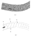
Images



Classifications
-
- G—PHYSICS
- G01—MEASURING; TESTING
- G01C—MEASURING DISTANCES, LEVELS OR BEARINGS; SURVEYING; NAVIGATION; GYROSCOPIC INSTRUMENTS; PHOTOGRAMMETRY OR VIDEOGRAMMETRY
- G01C21/00—Navigation; Navigational instruments not provided for in groups G01C1/00 - G01C19/00
- G01C21/26—Navigation; Navigational instruments not provided for in groups G01C1/00 - G01C19/00 specially adapted for navigation in a road network
- G01C21/28—Navigation; Navigational instruments not provided for in groups G01C1/00 - G01C19/00 specially adapted for navigation in a road network with correlation of data from several navigational instruments
- G01C21/30—Map- or contour-matching
-
- G—PHYSICS
- G01—MEASURING; TESTING
- G01C—MEASURING DISTANCES, LEVELS OR BEARINGS; SURVEYING; NAVIGATION; GYROSCOPIC INSTRUMENTS; PHOTOGRAMMETRY OR VIDEOGRAMMETRY
- G01C21/00—Navigation; Navigational instruments not provided for in groups G01C1/00 - G01C19/00
- G01C21/26—Navigation; Navigational instruments not provided for in groups G01C1/00 - G01C19/00 specially adapted for navigation in a road network
- G01C21/34—Route searching; Route guidance
- G01C21/36—Input/output arrangements for on-board computers
- G01C21/3626—Details of the output of route guidance instructions
- G01C21/3658—Lane guidance
-
- B—PERFORMING OPERATIONS; TRANSPORTING
- B60—VEHICLES IN GENERAL
- B60W—CONJOINT CONTROL OF VEHICLE SUB-UNITS OF DIFFERENT TYPE OR DIFFERENT FUNCTION; CONTROL SYSTEMS SPECIALLY ADAPTED FOR HYBRID VEHICLES; ROAD VEHICLE DRIVE CONTROL SYSTEMS FOR PURPOSES NOT RELATED TO THE CONTROL OF A PARTICULAR SUB-UNIT
- B60W40/00—Estimation or calculation of non-directly measurable driving parameters for road vehicle drive control systems not related to the control of a particular sub unit, e.g. by using mathematical models
- B60W40/02—Estimation or calculation of non-directly measurable driving parameters for road vehicle drive control systems not related to the control of a particular sub unit, e.g. by using mathematical models related to ambient conditions
- B60W40/06—Road conditions
- B60W40/072—Curvature of the road
-
- B—PERFORMING OPERATIONS; TRANSPORTING
- B60—VEHICLES IN GENERAL
- B60W—CONJOINT CONTROL OF VEHICLE SUB-UNITS OF DIFFERENT TYPE OR DIFFERENT FUNCTION; CONTROL SYSTEMS SPECIALLY ADAPTED FOR HYBRID VEHICLES; ROAD VEHICLE DRIVE CONTROL SYSTEMS FOR PURPOSES NOT RELATED TO THE CONTROL OF A PARTICULAR SUB-UNIT
- B60W30/00—Purposes of road vehicle drive control systems not related to the control of a particular sub-unit, e.g. of systems using conjoint control of vehicle sub-units
- B60W30/10—Path keeping
-
- B—PERFORMING OPERATIONS; TRANSPORTING
- B60—VEHICLES IN GENERAL
- B60W—CONJOINT CONTROL OF VEHICLE SUB-UNITS OF DIFFERENT TYPE OR DIFFERENT FUNCTION; CONTROL SYSTEMS SPECIALLY ADAPTED FOR HYBRID VEHICLES; ROAD VEHICLE DRIVE CONTROL SYSTEMS FOR PURPOSES NOT RELATED TO THE CONTROL OF A PARTICULAR SUB-UNIT
- B60W60/00—Drive control systems specially adapted for autonomous road vehicles
- B60W60/001—Planning or execution of driving tasks
-
- G—PHYSICS
- G05—CONTROLLING; REGULATING
- G05D—SYSTEMS FOR CONTROLLING OR REGULATING NON-ELECTRIC VARIABLES
- G05D1/00—Control of position, course, altitude or attitude of land, water, air or space vehicles, e.g. using automatic pilots
- G05D1/02—Control of position or course in two dimensions
- G05D1/021—Control of position or course in two dimensions specially adapted to land vehicles
- G05D1/0268—Control of position or course in two dimensions specially adapted to land vehicles using internal positioning means
- G05D1/0274—Control of position or course in two dimensions specially adapted to land vehicles using internal positioning means using mapping information stored in a memory device
-
- G—PHYSICS
- G05—CONTROLLING; REGULATING
- G05D—SYSTEMS FOR CONTROLLING OR REGULATING NON-ELECTRIC VARIABLES
- G05D1/00—Control of position, course, altitude or attitude of land, water, air or space vehicles, e.g. using automatic pilots
- G05D1/02—Control of position or course in two dimensions
- G05D1/021—Control of position or course in two dimensions specially adapted to land vehicles
- G05D1/0276—Control of position or course in two dimensions specially adapted to land vehicles using signals provided by a source external to the vehicle
- G05D1/0278—Control of position or course in two dimensions specially adapted to land vehicles using signals provided by a source external to the vehicle using satellite positioning signals, e.g. GPS
-
- B—PERFORMING OPERATIONS; TRANSPORTING
- B60—VEHICLES IN GENERAL
- B60W—CONJOINT CONTROL OF VEHICLE SUB-UNITS OF DIFFERENT TYPE OR DIFFERENT FUNCTION; CONTROL SYSTEMS SPECIALLY ADAPTED FOR HYBRID VEHICLES; ROAD VEHICLE DRIVE CONTROL SYSTEMS FOR PURPOSES NOT RELATED TO THE CONTROL OF A PARTICULAR SUB-UNIT
- B60W2420/00—Indexing codes relating to the type of sensors based on the principle of their operation
- B60W2420/40—Photo, light or radio wave sensitive means, e.g. infrared sensors
- B60W2420/403—Image sensing, e.g. optical camera
-
- B—PERFORMING OPERATIONS; TRANSPORTING
- B60—VEHICLES IN GENERAL
- B60W—CONJOINT CONTROL OF VEHICLE SUB-UNITS OF DIFFERENT TYPE OR DIFFERENT FUNCTION; CONTROL SYSTEMS SPECIALLY ADAPTED FOR HYBRID VEHICLES; ROAD VEHICLE DRIVE CONTROL SYSTEMS FOR PURPOSES NOT RELATED TO THE CONTROL OF A PARTICULAR SUB-UNIT
- B60W2420/00—Indexing codes relating to the type of sensors based on the principle of their operation
- B60W2420/40—Photo, light or radio wave sensitive means, e.g. infrared sensors
- B60W2420/408—Radar; Laser, e.g. lidar
-
- B—PERFORMING OPERATIONS; TRANSPORTING
- B60—VEHICLES IN GENERAL
- B60W—CONJOINT CONTROL OF VEHICLE SUB-UNITS OF DIFFERENT TYPE OR DIFFERENT FUNCTION; CONTROL SYSTEMS SPECIALLY ADAPTED FOR HYBRID VEHICLES; ROAD VEHICLE DRIVE CONTROL SYSTEMS FOR PURPOSES NOT RELATED TO THE CONTROL OF A PARTICULAR SUB-UNIT
- B60W2520/00—Input parameters relating to overall vehicle dynamics
- B60W2520/06—Direction of travel
-
- B—PERFORMING OPERATIONS; TRANSPORTING
- B60—VEHICLES IN GENERAL
- B60W—CONJOINT CONTROL OF VEHICLE SUB-UNITS OF DIFFERENT TYPE OR DIFFERENT FUNCTION; CONTROL SYSTEMS SPECIALLY ADAPTED FOR HYBRID VEHICLES; ROAD VEHICLE DRIVE CONTROL SYSTEMS FOR PURPOSES NOT RELATED TO THE CONTROL OF A PARTICULAR SUB-UNIT
- B60W2520/00—Input parameters relating to overall vehicle dynamics
- B60W2520/28—Wheel speed
-
- B—PERFORMING OPERATIONS; TRANSPORTING
- B60—VEHICLES IN GENERAL
- B60W—CONJOINT CONTROL OF VEHICLE SUB-UNITS OF DIFFERENT TYPE OR DIFFERENT FUNCTION; CONTROL SYSTEMS SPECIALLY ADAPTED FOR HYBRID VEHICLES; ROAD VEHICLE DRIVE CONTROL SYSTEMS FOR PURPOSES NOT RELATED TO THE CONTROL OF A PARTICULAR SUB-UNIT
- B60W2556/00—Input parameters relating to data
- B60W2556/20—Data confidence level
Definitions
- Example embodiments presented herein are directed towards a method and a unit for adjusting a road boundary of a two dimensional virtual representation of a road for path planning of an autonomous vehicle.
- An autonomous vehicle is one which is capable of sensing its environment and navigating without the use of human input. It is envisioned that such vehicles will be capable of transitioning from an autonomous driving mode and a manual driving mode, in which a driver manually operates the vehicle. It is further envisioned that such autonomous driving may only be allowed on preapproved or certified roads or zones. Thus, a vehicle's initial driving segment will likely require the human driver to control the vehicle and later transition to an autonomous driving mode. While in an autonomous driving mode, a driver of a vehicle may engage in activities which may not be possible while the vehicle is in a manual driving mode. Examples of such activities are sleeping, working or using multimedia applications. Final segment may be initiated by the driver taking back control of the vehicle to depart the certified road and driving manually until destination is reached.
- US2013261870A discloses an autonomous machine control system includes a positioning unit measuring position and orientation, and a navigation unit storing a route plan including an intended travel path along a lane.
- the lane has a width defined by a left-hand boundary and a right-hand boundary.
- the navigation unit receives an uncertainty value associated with the position or orientation, and creates a virtual two-dimensional footprint based on an actual machine footprint and the uncertainty value.
- the navigation unit also simulates movement of the virtual footprint along the intended travel path, calculates a left-hand margin value defined by the virtual footprint and the left-hand boundary, and calculates a right-hand margin value defined by the virtual footprint and the right-hand boundary.
- the margin values are compared to a predetermined value, and speed or travel direction of the machine is controlled if either of the margin values is below the predetermined value.
- US6393362 discloses that the function of each autonomous vehicle in a surface mine is performed according to a predetermined trajectory related to its particular task and implemented by a guidance system through on-board GPS and two-way communication hardware.
- the current position of the vehicle is continuously monitored and correlated to the position of potential hazards along its path, so that corrective action can be taken by implementing appropriate, predetermined control strategies.
- Each vehicle is assigned a safety envelope that accounts for the vehicle's physical presence and operating tolerances.
- the safety envelope is characteristic of each vehicle and is defined by a variable space surrounding the vehicle wherein it may be physically present as it travels along its intended trajectory.
- the shape and size of the safety envelope is dynamically varied to meet safety requirements for current trajectory conditions facing the vehicle as it performs its autonomous function along its predetermined path.
- the safety envelope is changed according to a predetermined set of rules specific to the vehicle. Intersections between predetermined vehicle trajectories along paths and roadways within the mine's property are identified dynamically by monitoring current traffic conditions and establishing locations where the safety envelopes of vehicles traveling along approaching trajectories could overlap.
- WO 2008089966 discloses a method and system for video-based road departure warning for a vehicle on a road.
- Road departure warning involves receiving an image of a road in front of the vehicle from a video imager, and detecting one or more road markings in the image corresponding to markings on the road. Then, analyzing the characteristics of an image region beyond the detected markings to determine a rating for drivability of the road corresponding to said image region, and detecting the lateral offset of the vehicle relative to the markings on the road based on the detected road markings.
- a warning signal is generated as function of said lateral offset and said rating.
- US 20080243378 discloses a navigation system for use in a vehicle.
- the system includes an absolute position sensor, such as GPS, in addition to one or more additional sensors, such as a camera, laser scanner, or radar.
- the system further comprises a digital map or database that includes records for at least some of the vehicle's surrounding objects. These records can include relative positional attributes and traditional absolute positions.
- sensors sense the presence of at least some of these objects, and measure the vehicle's relative position to those objects.
- This information together with the absolute positional information and the added map information, is used to determine the vehicle's location, and support features such as enhanced driving directions, collision avoidance, or automatic assisted driving.
- the system also allows some objects to be attributed using relative positioning, without recourse to storing absolute position information.
- a unit for adjusting a road boundary of a two dimensional virtual representation of a road for path planning of an autonomous vehicle comprises a retrieval unit configured to retrieve a measured position and a measured heading angle of the vehicle with respect to a reference.
- the unit also comprises an uncertainty unit configured to receive as input the measured position, the measured heading angle and map data of the road.
- the uncertainty unit further configured to determine a position uncertainty value and a heading angle uncertainty value representing an amount of uncertainty in the vehicle's position and heading angle, respectively, on the road based on the input.
- the unit further comprises an adjustment unit configured to adjust a width and a heading angle of a drivable portion of the two dimensional virtual representation of the road, wherein the adjustment of the width and heading angle is based on the position uncertainty value and the heading angle uncertainty value, respectively.
- the unit can compute an estimate or measure of the vehicle position and heading angle and a corresponding uncertainty measure or value which reflects the accuracy of the estimate of the position and heading angle.
- a drivable portion of the road ahead of the vehicle can be determined and adjusted regularly or continually as the vehicle drives along the road. This determined drivable portion is safe to drive in for the vehicle, as the certainty or probability that the drivable portion is in fact drivable is determined, and the level or threshold for the certainty or probability can be adjusted as well.
- changing conditions in the road curvature, weather, sensor performance etc. can be accounted for.
- the estimates or measures of the positioning and heading angle of the vehicle which are not exact itself, are provided with an associated uncertainty or confidence measure which is taken into account when expressing the drivable portion or are of the road.
- the positioning uncertainty is comprised in the definition or determination of the drivable portion of the road.
- the unit provides a solution to the problem that the uncertainties in the ego vehicle positioning estimate will propagate to the generated drivable area.
- the drivable area may be expressed in the ego vehicle's local coordinate system and since the exact position of the ego vehicle is not known, then neither is the exact location of the drivable area.
- the solution to the problem is that the positioning uncertainty influences the size of the drivable area. Thus if the uncertainty is large, the size of the drivable area will be small, and if the uncertainty is low, the size of the drivable area will be large.
- the drivable area may thus for example be computed so that all points inside the area have a probability of residing between the road boundaries, and this probability must be higher than a certain probability threshold.
- the autonomous vehicle may be a self-driven car or another vehicle, such as a truck, a motorcycle etc.
- the road boundaries of the two dimensional virtual representation can be represented as a list of global coordinates for each boundary, or as parametrized curves, e.g. splines.
- the road boundaries define the drivable portion of the road for the vehicle.
- the two dimensional virtual representation of the road may be a grid representation.
- the two dimensional virtual representation of the road may be a polygonal chain representation.
- the two dimensional (2D) virtual representation of the road boundaries is configured to provide the road boundaries to a path planning part or unit of the vehicles.
- the 2D representation is the exact location of the physical boundaries of the road stored on the map.
- the position and heading angle may be measured or estimated by using internal sensor and/or external sensors in/on the vehicle, by means of data from a satellite navigation system, such as the global positioning system (GPS) or a system similar to GPS, by means of data from an inertial measurement unit (IMU), by means of data from a map.
- a satellite navigation system such as the global positioning system (GPS) or a system similar to GPS
- IMU inertial measurement unit
- an uncertainty in position and heading angle of the vehicle can be determined or measured.
- the uncertainty of the sensors may be determined beforehand, i.e. before the vehicle starts driving, such as at the vehicle manufacturer before the vehicle is sold to its owner, or performed at regular intervals in the vehicle, such as every time the vehicle is started, or such as once every days, or such as for every 100 kilometers, every 500 kilometers, every 1000 kilometers etc, which the vehicle has driven.
- the uncertainty of the sensors may be determined by means of a reference sensor, i.e. the uncertainty may be modelled with regard to a reference sensor.
- each sensor is not only sensor specific, but also depends on the environment, such as light conditions, weather conditions etc. For example the uncertainty of a sensor is higher if it is dark outside e.g. in the night, if it rains or snows etc.
- the sensor uncertainty also depends on the location of the vehicle, such as depending on the amount and/or size of landmarks etc. which the sensor can detect.
- the map may be a standard map, or an extended or special map comprising more information, such as a dense map, a high-definition (HD) map, a high-resolution map, an augmented map etc., which is a map comprising more data and information about the surroundings, such as of landmarks, guide rails, road lanes etc.
- the map may be stored in the vehicle, such as in a unit or a GPS unit in the vehicle, or the map may be stored in a remote storage, such as in a cloud storage.
- the map may be used to look up in, such as look up the position of the vehicle. As the vehicle moves, the map may be looked up in continuously.
- the position may be defined by means of a lateral position and a longitudinal position.
- the heading angle is the angle of the vehicle, i.e. the angle of a longitudinal axis of the vehicle, relative to the driving lane.
- heading angle corresponds to direction, orientation and/or the like.
- the measured position and the measured heading angle of the vehicle is with respect to a reference, and the reference may be a landmark on the road, a GPS map position, a position in fixed coordinate system, such as in a local or global coordinate system.
- a landmark may be a road sign, a building etc. with an exact position, such as an exact GPS.
- a landmark may be an advantage to use to measure the exact position of the vehicle.
- the landmark is identified by means of the internal and/or external sensors in the vehicle, e.g. sensors in the form of cameras, lasers, lidars, and by knowledge of the position of the landmark from map data.
- Input data to the unit may thus comprise data about landmarks, such as the shape and position of the landmark, the type of landmark etc. As the vehicle drives along the road new or other landmarks may be detected continuously by the sensors in the vehicle.
- the uncertainty values reflect the accuracy of the measured position and heading angle. The lower the uncertainty is, the higher is the accuracy of the measured position and heading angle, and the higher the uncertainty is, the lower is the accuracy of the measured position and heading angle.
- the drivable portion is a drivable area or part of the road.
- the adjustment of the width and heading angle of the drivable portion may be performed such that the certainty is for example 99.9% that the drivable portion is drivable road.
- the width of the drivable portion which can be adjusted may be an adjustment in the lateral position of the vehicle on the road.
- the unit may be a central processing unit (CPU), a processing unit, a processor, a control part of a path planning part and/or the like.
- CPU central processing unit
- processing unit a processing unit
- processor a control part of a path planning part and/or the like.
- the retrieval unit is configured to retrieve the measured position and the measured heading angle at predetermined time intervals
- the uncertainty unit is configured to determine the position uncertainty value and the heading angle uncertainty value at predetermined time intervals
- the adjustment unit is configured to adjust the width and angle of the drivable portion of the road at predetermined time intervals.
- these steps of retrieving, determining and adjusting may occur at regular time intervals.
- the time intervals for the different steps may different or the same.
- the time intervals may be predetermined, and may occur such as every 1 millisecond (ms), every 2 ms, every 5 ms, every 10 ms, every 15 ms, every 20 ms, every 25 ms, every 30 ms, every 40 ms, every 50 ms, every 100 ms etc.
- the reference is a landmark on the road, a map position in a satellite navigation system, such as GPS, and/or a position in a fixed coordinate system.
- the uncertainty unit is further configured to determine the position uncertainty value and the heading angle uncertainty value from a probability distribution, where the probability distribution is based on a filter computation.
- the input and data to make the probability distribution from is the measured position, the measured heading angle and map data of the road.
- the probability distribution is an output of a filter.
- the probability distribution may be a Gaussian distribution, i.e. a normal distribution etc.
- the uncertainty unit is further configured to receive a measured speed and direction of the vehicle as an input for determining the position uncertainty value and the heading angle uncertainty value.
- the measured speed and direction of the vehicle may be measured by means of internal sensors in the vehicle.
- the measured speed of the vehicle may be measured by means of a wheel speed sensor.
- the measured direction of the vehicle may be measured by means of an inertial measurement unit (IMU) providing yaw rate of the vehicle etc.
- IMU inertial measurement unit
- the filter computation is based on the input in the form of the measured position, the measured heading angle and map data of the road.
- the filter of the filter computation is a Bayesian filter, such as a particle filter, or a Kalman filter, such as a regular Kalman filter, an extended Kalman filter or an unscented Kalman filter.
- the filter e.g. the Bayesian filters
- the input i.e. the measurements from e.g. GPS, IMU, relative measurements to landmarks, and the map, to compute the probability distribution. From this probability distribution it is possible to both compute an estimate of the position and the heading angle as well as an associated uncertainty value of the position and heading angle.
- the uncertainty unit is configured to generate a number of samples from the probability distribution, where each sample comprises a position estimate and a heading angle estimate.
- the uncertainty unit is further configured to determine the position uncertainty value for each position estimate, where the position uncertainty value is based on the amount of samples generated with the respective position estimate.
- the uncertainty unit is also configured to determine the heading angle uncertainty value for each heading angle estimate, where the heading angle uncertainty value is based on the amount of samples generated with the respective heading angle estimate.
- samples are generated from the probability distribution, as the samples may provide a more correct and accurate measure of the position and heading angle than the actual measurements.
- the samples will not contain any uncertainty values. By drawing samples from the distribution, one will obtain few unlikely samples and multiple copies of likely samples.
- the position uncertainty value and the heading angle uncertainty value are then described by the amount of samples that is generated with a certain position and heading angle value, respectively. For example, the position uncertainty value and the heading angle uncertainty value are low, when the number or amount of samples with the respective position and heading angle measure is high, and the position uncertainty value and the heading angle uncertainty value are high, when the number or amount of samples for the respective position and heading angle measure are low.
- Generating samples according to the above from a probability distribution is common for a number of methods which may be used in the present invention. These methods may be termed the Monto Carlo method and a deterministic sampling method.
- a number of models may be used for representing the road, for example a grid representation and a polygonal chain representation.
- a method and a road representation may be a deterministic sampling with a polygonal chain representation, or be a deterministic sampling with a grid representation, or an optimal sampling, such as selecting optimal samples, with polygonal chain representation etc..
- the determination of which samples that are optimal may be based on a number of predefined parameters etc.
- the samples may be selected or generated deterministically, such as generated using or based on a deterministic sampling.
- the samples may be generated using or based on a Monte Carlo grid representation.
- the samples may be generated for every 1 meter of the road, for every 50 cm, for every 25 cm, or for every 1.5 m of the road etc.
- the adjustment unit is configured to determine for each sample the portion in front of the vehicle which is drivable.
- the adjustment unit is further configured to accumulate the portions determined to be drivable.
- the adjustment unit is also configured to compute the drivable portion of the two dimensional virtual representation of the road, from the accumulated portions determined to be drivable, to be a portion in which the amount of samples generated with the respective position estimate and the respective heading angle estimate is higher than a certain threshold.
- the portion in which the amount of samples generated with the respective position estimate and the respective heading angle estimate is higher than a certain threshold corresponds to the portion in which the uncertainty value is lower than a certain threshold.
- the uncertainty value must be lower than a certain threshold in order for the portion to be drivable.
- a certainty value must be higher than a certain threshold in order for the portion to be drivable, where the certainty value is based on the amount of samples generated with the respective position estimate and the respective heading angle estimate.
- the position uncertainty value and the heading angle uncertainty value are estimates comprising a confidence or accuracy level or interval.
- the estimates of the position uncertainty value may be represented as ⁇ x for the lateral or x-axis position, and as ⁇ y for the longitudinal or y-axis position.
- the estimates of the heading angle uncertainty value may be represented as ⁇ .
- the position uncertainty value and the heading angle uncertainty value are affected by environmental factors in the surroundings of the vehicle and/or quality of one or more sensors used to measure the position and heading angle of the vehicle and/or quality of the map data of the road.
- the environmental factors may for example be weather, e.g. rain, snow; lightning conditions, e.g. daylight or night; temperature, e.g. freezing temperatures, heat waves etc.
- a vehicle comprising a unit according to any of the preceding embodiments.
- a method for adjusting a road boundary of a two dimensional virtual representation of a road for path planning of an autonomous vehicle performed in a unit comprises retrieving a measured position and a measured heading angle of the vehicle with respect to a reference in a retrieval unit.
- the method further comprises receiving as input the measured position, the measured heading angle and map data of the road in an uncertainty unit.
- the method also comprises determining a position uncertainty value and a heading angle uncertainty value representing an amount of uncertainty in the vehicle's position and heading angle, respectively, on the road based on the input, in the uncertainty unit.
- the method additionally comprises adjusting a width and a heading angle of a drivable portion of the two dimensional virtual representation of the road in an adjustment unit, wherein the adjustment of the width and heading angle is based on the position uncertainty value and the heading angle uncertainty value, respectively.
- a computer readable medium comprising program instructions for adjusting a road boundary of a two dimensional virtual representation of a road for path planning of an autonomous vehicle performed in a unit, wherein execution of the program instructions by one or more processors of a computer system causes the one or more processors to carry out the steps of retrieving a measured position and a measured heading angle of the vehicle with respect to a reference; receiving as input the measured position, the measured heading angle and map data of the road; determining a position uncertainty value and a heading angle uncertainty value representing an amount of uncertainty in the vehicle's position and heading angle, respectively, on the road based on the input; and adjusting a width and a heading angle of a drivable portion of the two dimensional virtual representation of the road, wherein the adjustment of the width and heading angle is based on the position uncertainty value and the heading angle uncertainty value, respectively.
- the computer readable medium further comprises executable instructions causing one or more processors to carry out the steps of the method above.
- At least one example object of some of the example embodiments described herein is to provide a system in which a driver and/or passenger of a vehicle may schedule activities during an autonomous driving mode which may not necessarily be possible during a manual driving mode.
- the navigation task consists of two steps: first a path planning step, which selects a safe trajectory for the vehicle, and second a control part which steers the vehicle along the selected path.
- the path planning algorithm needs a detailed description of the road ahead.
- a common approach is to store this detailed road description in an accurate map and then have a system determining the vehicle position in the map. Using the estimated position of the vehicle, a description of the road ahead can be extracted from the map.
- this description is referred to as a "drivable portion" or the "drivable area”
- Fig. 1 shows a system architecture of how the drivable area is generated.
- the positioning filter estimates the vehicle position by matching the sensor measurements of landmarks with the exact positions of the landmarks stored in the map, MAP in the figure.
- the dynamic properties of the vehicle may be speed, acceleration, rotation, yaw rate estimation, orientation or heading angle etc.
- the sensors measuring the dynamic properties of the vehicle and the position and properties of surrounding landmarks may be external sensors and/or internal sensors in the vehicle.
- the sensors may be devices communicating with space-based satellite navigation systems, such as the Global Positioning System (GPS), inertial measurement units (IMUs), cameras, radar sensors, lidar sensor, accelerometers, gyroscopes etc.
- GPS Global Positioning System
- IMUs inertial measurement units
- radar sensors lidar sensor
- accelerometers gyroscopes etc.
- the sensors may be used for sensing or capturing landmarks in the surroundings, such as traffic signs, and/or may be used for sensing or capturing lines on the road etc.
- the sensors, such as cameras may be configured to sense or capture certain things in the surroundings, such as buildings etc.
- the sensors such as lasers or laser scanners, may be used for sensing, scanning, capturing objects, such as road barriers, traffic signs etc.
- the sensors such as radars, such may be used for sensing, or capturing road barriers etc.
- the external sensors such as cameras, lasers, radars etc. may capture and/or transmit data to the positioning filter or ego vehicle positioning filter at predetermined time intervals, such as every 40 milliseconds.
- the internal sensors such as vehicle speed sensors, IMU, gyroscopes, accelerometers etc., may capture and/or transmit data to the positioning filter or ego vehicle positioning filter continuously or constantly or at predetermined time intervals, such as every 1 millisecond. Thus the internal sensor data may be captured and/or transmitted more often than the external sensor data.
- the landmarks may be stationary objects which can be represented in a map, such as unique objects, such as buildings, mountains, tunnels, road signs, traffic signs etc.
- the map may be a two dimensional (2D) map stored in a GPS unit in the vehicle, it may be high definition (HD) map comprising more information about the road and its surroundings than a standard map etc.
- 2D two dimensional
- HD high definition
- the GPS provides the global position of the vehicle to the ego vehicle positioning filter.
- the IMU provides a change in the global position of the vehicle to the ego vehicle positioning filter.
- the sensors, sensor 1,... sensor N provides information and position of landmarks to the ego vehicle positioning filter.
- the map provides sensor models of the landmarks to the ego vehicle positioning filter.
- the ego vehicle positioning filter estimates an ego vehicle map position which is provided to the unit or module generating the drivable area. Information about the road boundaries of the road from the map is also provided to the module generating the drivable area.
- the output of the module generating the drivable area is the drivable area, and this drivable area is inputted to the path planning module or unit.
- the module or unit in Fig. 1 called “Generate drivable area” combines the positioning estimate with the exact location of the physical boundaries of the road stored in the map. These boundaries can be represented in many different ways, for instance as a list of global coordinates for each boundary, or as parametrized curves, e.g. splines.
- the positioning estimate is not exact, but has an associated uncertainty/confidence measure that needs to be taken into account when expressing the drivable portion.
- the unit and method described in the claims and in this description suggests a solution to how the positioning uncertainty can be included into the estimate or measure of the drivable area. More details on the drivable area invention are presented below.
- the task of the ego vehicle positioning filter is to compute an estimate of the vehicle position and a corresponding uncertainty measure reflecting the accuracy of the estimate.
- the position can be expressed using many different parametrizations and coordinate systems.
- the ego vehicle position may be expressed in a curved coordinate system (xt; yt) as is shown in Fig. 2 .
- xt is the longitudinal position along the road at time t
- yt is the lateral position in the lane.
- the ego vehicle positioning filter, or positioning filter estimates the heading angle ⁇ t relative to the lane and a discrete parameter Lat which corresponds to in which lane the ego vehicle is positioned.
- the heading angle ⁇ t is a direction or orientation relative to the lane and the heading angle ⁇ t may correspond to an orientation, a directions, etc.
- a Bayesian approach may be used in which the positioning filter computes the posterior distribution p( x t
- the posterior probability of a random event or an uncertain proposition is the conditional probability that is assigned after the relevant evidence or background is taken into account.
- the posterior probability distribution is the probability distribution of an unknown quantity, treated as a random variable, conditional on the evidence obtained from an experiment or survey.
- the task of the module or unit generating the drivable area or drivable portion is to provide the path planning module with a description or information of the area in front of the ego vehicle which is safe to drive in, and is expressed in the vehicle's local Cartesian coordinate system (xego; yego).
- a complication, which is also solved by the unit and method of the present application, is that the uncertainties in the ego vehicle positioning estimate will propagate to the generated drivable area. This is because the drivable area is expressed in the ego vehicle's local coordinate system and since the exact position of the ego vehicle is not known, then neither is the exact location of the drivable area.
- the positioning uncertainty may influence the size of the drivable area. If the positioning uncertainty is large or high, the size of the drivable area will be small, and vice versa, i.e. if the positioning uncertainty is low, the size of the drivable area or drivable portion is large.
- a general idea is to compute the drivable area so that all points inside the area have a probability of residing between the road boundaries that is higher than a certain threshold.
- the figures 3-5 which show how the uncertainties in position and heading affect the drivable area. In figs 3-5 , the true road boundaries 301 stored in the map are represented by the dashed lines and the resulting drivable area 302 is between the dotted lines.
- Fig. 3 shows that the drivable area 302 is affected by the uncertainty in the orientation or heading angle, indicated by curved arrows, of the ego vehicle 303.
- the drivable area 302 close to the vehicle 303 almost as wide as the true area indicated by the road boundaries 301 stored in the map, whereas it is reduced further away.
- Fig. 4 shows that the drivable area 302 is affected by the uncertainty in the lateral position, indicated by lateral arrows, of the ego vehicle 303.
- the drivable area 302 is reduced by the same size relative to the road boundaries 301 along the road.
- Fig. 5 shows that the drivable area 302 is affected by the uncertainty in the longitudinal position, indicated by longitudinal arrows, of the ego vehicle 303.
- the drivable area 302 close to the vehicle 303 is as wide as the true area indicated by the road boundaries 301 stored in the map, whereas it is reduced further away.
- Fig. 6 illustrates a method, e.g. a Monto Carlo method, which divides the area in front of the ego vehicle 303 into a grid 604 and computes the probability that each cell 605 in the grid 604 is located on the road indicated by the road boundaries 301, dashed lines.
- the probability is computed using a Monte Carlo method, in which a large number of independent samples are drawn from the posterior distribution x(i) t ⁇ p(xt
- Z 0:t ; M ), i 1, ... ,N. For each sample x(i) t , it is evaluated which of the cells 605 in the grid 604 are on the road and which are not.
- a grid By accumulating the results from all samples, a grid can be constructed, where each cell contains the number of samples for which that particular cell was evaluated to be on the road. The result would be similar to what is shown in Fig. 6 .
- a deterministic drivable area 302 By setting a threshold on how large probability is required in each cell 605 for it to be considered part of the road, a deterministic drivable area 302, indicated by dotted line, can be generated.
- the threshold on how large probability is required in each cell 605 for it to be considered part of the road 301 may be e.g. 99%, such as 99.9%, as the safety is of optimum importance for autonomous vehicles.
- the 99.9% probability may be indicated by the dark cells in the grid 604.
- the 99% probability may be indicated by the grey cells in the grid.
- Monte Carlo methods or Monte Carlo experiments, are a broad class of computational algorithms that rely on repeated random sampling to obtain numerical results; typically one runs simulations many times over in order to obtain the distribution of an unknown probabilistic entity.
- a deterministic sampling method with a grid representation A deterministic sampling method with a grid representation.
- a deterministic sampling method with a polygonal chain representation A deterministic sampling method with a polygonal chain representation.
- the third method see fig. 7 , represents the drivable area 302 using a pair of polygonal chains, one or a first polygonal chain 706 for the left boundary and one or a second polygonal chain 707 for the right boundary.
- Fig. 7 a simplified example is shown, in which the dashed lines are the true drivable area indicated by the road boundaries 301 and the dotted lines 706y, 706 ⁇ , 707y, 707 ⁇ are the results of transforming these boundaries using two different values of ⁇ t and two different values of yt thereby obtaining the computed drivable area 302.
- This fourth method uses the same polygonal chain representation as the third method, see fig. 7 , but the samples are not selected deterministically. Instead they are computed like this: for each longitudinal coordinate find the optimal sample x(i) t which is on a selected contour line of the probability distribution p(xt
- Fig. 8 shows an illustrative example of a unit configured for adjusting a road boundary of a two dimensional virtual representation of a road for path planning of an autonomous vehicle.
- the unit 809 for adjusting a road boundary comprises a retrieval unit 810 configured to retrieve a measured position and a measured heading angle of the vehicle with respect to a reference.
- the unit 809 comprises an uncertainty unit 811 configured to receive as input the measured position, the measured heading angle and map data of the road.
- the uncertainty unit 811 is further configured to determine a position uncertainty value and a heading angle uncertainty value representing an amount of uncertainty in the vehicle's position and heading angle, respectively, on the road based on the input.
- the unit 809 comprises an adjustment unit 812 configured to adjust a width and a heading angle of a drivable portion of the two dimensional virtual representation of the road, wherein the adjustment of the width and heading angle is based on the position uncertainty value and the heading angle uncertainty value, respectively.
- Fig. 9 schematically illustrates a vehicle 303 comprising a unit 809 configured for adjusting a road boundary of a two dimensional virtual representation of a road for path planning of an autonomous vehicle.
- the unit 809 may be placed in other positions in the vehicle 303 than shown on the figure.
- Fig. 10 illustrates a flow chart of a method for adjusting a road boundary of a two dimensional virtual representation of a road for path planning of an autonomous vehicle performed in a unit.
- the method comprises:
- a position uncertainty value and a heading angle uncertainty value are determined in the uncertainty unit, the position uncertainty value and a heading angle uncertainty value represents an amount of uncertainty in the vehicle's position and heading angle, respectively, on the road based on the input.
- a width and a heading angle of a drivable portion of the two dimensional virtual representation of the road is adjusted in an adjustment unit, wherein the adjustment of the width and heading angle is based on the position uncertainty value and the heading angle uncertainty value, respectively.
- a computer-readable medium may include removable and non-removable storage devices including, but not limited to, Read Only Memory (ROM), Random Access Memory (RAM), compact discs (CDs), digital versatile discs (DVD), etc.
- program modules may include routines, programs, objects, components, data structures, etc. that perform particular tasks or implement particular abstract data types.
- Computer-executable instructions, associated data structures, and program modules represent examples of program code for executing steps of the methods disclosed herein. The particular sequence of such executable instructions or associated data structures represents examples of corresponding acts for implementing the functions described in such steps or processes.
Landscapes
- Engineering & Computer Science (AREA)
- Radar, Positioning & Navigation (AREA)
- Remote Sensing (AREA)
- Automation & Control Theory (AREA)
- Physics & Mathematics (AREA)
- General Physics & Mathematics (AREA)
- Aviation & Aerospace Engineering (AREA)
- Mechanical Engineering (AREA)
- Transportation (AREA)
- Mathematical Physics (AREA)
- Human Computer Interaction (AREA)
- Navigation (AREA)
- Traffic Control Systems (AREA)
- Business, Economics & Management (AREA)
- Health & Medical Sciences (AREA)
- Artificial Intelligence (AREA)
- Evolutionary Computation (AREA)
- Game Theory and Decision Science (AREA)
- Medical Informatics (AREA)
Abstract
Description
- Example embodiments presented herein are directed towards a method and a unit for adjusting a road boundary of a two dimensional virtual representation of a road for path planning of an autonomous vehicle.
- An autonomous vehicle is one which is capable of sensing its environment and navigating without the use of human input. It is envisioned that such vehicles will be capable of transitioning from an autonomous driving mode and a manual driving mode, in which a driver manually operates the vehicle. It is further envisioned that such autonomous driving may only be allowed on preapproved or certified roads or zones. Thus, a vehicle's initial driving segment will likely require the human driver to control the vehicle and later transition to an autonomous driving mode. While in an autonomous driving mode, a driver of a vehicle may engage in activities which may not be possible while the vehicle is in a manual driving mode. Examples of such activities are sleeping, working or using multimedia applications. Final segment may be initiated by the driver taking back control of the vehicle to depart the certified road and driving manually until destination is reached.
-
US2013261870A discloses an autonomous machine control system includes a positioning unit measuring position and orientation, and a navigation unit storing a route plan including an intended travel path along a lane. The lane has a width defined by a left-hand boundary and a right-hand boundary. The navigation unit receives an uncertainty value associated with the position or orientation, and creates a virtual two-dimensional footprint based on an actual machine footprint and the uncertainty value. The navigation unit also simulates movement of the virtual footprint along the intended travel path, calculates a left-hand margin value defined by the virtual footprint and the left-hand boundary, and calculates a right-hand margin value defined by the virtual footprint and the right-hand boundary. The margin values are compared to a predetermined value, and speed or travel direction of the machine is controlled if either of the margin values is below the predetermined value. -
US6393362 discloses that the function of each autonomous vehicle in a surface mine is performed according to a predetermined trajectory related to its particular task and implemented by a guidance system through on-board GPS and two-way communication hardware. The current position of the vehicle is continuously monitored and correlated to the position of potential hazards along its path, so that corrective action can be taken by implementing appropriate, predetermined control strategies. Each vehicle is assigned a safety envelope that accounts for the vehicle's physical presence and operating tolerances. The safety envelope is characteristic of each vehicle and is defined by a variable space surrounding the vehicle wherein it may be physically present as it travels along its intended trajectory. The shape and size of the safety envelope is dynamically varied to meet safety requirements for current trajectory conditions facing the vehicle as it performs its autonomous function along its predetermined path. The safety envelope is changed according to a predetermined set of rules specific to the vehicle. Intersections between predetermined vehicle trajectories along paths and roadways within the mine's property are identified dynamically by monitoring current traffic conditions and establishing locations where the safety envelopes of vehicles traveling along approaching trajectories could overlap. -
WO 2008089966 discloses a method and system for video-based road departure warning for a vehicle on a road. Road departure warning involves receiving an image of a road in front of the vehicle from a video imager, and detecting one or more road markings in the image corresponding to markings on the road. Then, analyzing the characteristics of an image region beyond the detected markings to determine a rating for drivability of the road corresponding to said image region, and detecting the lateral offset of the vehicle relative to the markings on the road based on the detected road markings. A warning signal is generated as function of said lateral offset and said rating. -
US 20080243378 discloses a navigation system for use in a vehicle. The system includes an absolute position sensor, such as GPS, in addition to one or more additional sensors, such as a camera, laser scanner, or radar. The system further comprises a digital map or database that includes records for at least some of the vehicle's surrounding objects. These records can include relative positional attributes and traditional absolute positions. As the vehicle moves, sensors sense the presence of at least some of these objects, and measure the vehicle's relative position to those objects. This information, together with the absolute positional information and the added map information, is used to determine the vehicle's location, and support features such as enhanced driving directions, collision avoidance, or automatic assisted driving. In accordance with an embodiment, the system also allows some objects to be attributed using relative positioning, without recourse to storing absolute position information. - Disclosed is a unit for adjusting a road boundary of a two dimensional virtual representation of a road for path planning of an autonomous vehicle. The unit comprises a retrieval unit configured to retrieve a measured position and a measured heading angle of the vehicle with respect to a reference. The unit also comprises an uncertainty unit configured to receive as input the measured position, the measured heading angle and map data of the road. The uncertainty unit further configured to determine a position uncertainty value and a heading angle uncertainty value representing an amount of uncertainty in the vehicle's position and heading angle, respectively, on the road based on the input. The unit further comprises an adjustment unit configured to adjust a width and a heading angle of a drivable portion of the two dimensional virtual representation of the road, wherein the adjustment of the width and heading angle is based on the position uncertainty value and the heading angle uncertainty value, respectively.
- Thus it is an advantage that the unit can compute an estimate or measure of the vehicle position and heading angle and a corresponding uncertainty measure or value which reflects the accuracy of the estimate of the position and heading angle. Thus a drivable portion of the road ahead of the vehicle can be determined and adjusted regularly or continually as the vehicle drives along the road. This determined drivable portion is safe to drive in for the vehicle, as the certainty or probability that the drivable portion is in fact drivable is determined, and the level or threshold for the certainty or probability can be adjusted as well. Hereby changing conditions in the road curvature, weather, sensor performance etc. can be accounted for.
- It is an advantage that the estimates or measures of the positioning and heading angle of the vehicle, which are not exact itself, are provided with an associated uncertainty or confidence measure which is taken into account when expressing the drivable portion or are of the road. Thus the positioning uncertainty is comprised in the definition or determination of the drivable portion of the road.
- It is an advantage that the unit provides a solution to the problem that the uncertainties in the ego vehicle positioning estimate will propagate to the generated drivable area.
- The reason for this problem is that the drivable area may be expressed in the ego vehicle's local coordinate system and since the exact position of the ego vehicle is not known, then neither is the exact location of the drivable area. The solution to the problem is that the positioning uncertainty influences the size of the drivable area. Thus if the uncertainty is large, the size of the drivable area will be small, and if the uncertainty is low, the size of the drivable area will be large. The drivable area may thus for example be computed so that all points inside the area have a probability of residing between the road boundaries, and this probability must be higher than a certain probability threshold.
- The autonomous vehicle may be a self-driven car or another vehicle, such as a truck, a motorcycle etc.
- The road boundaries of the two dimensional virtual representation can be represented as a list of global coordinates for each boundary, or as parametrized curves, e.g. splines.
- The road boundaries define the drivable portion of the road for the vehicle.
- The two dimensional virtual representation of the road may be a grid representation.
- Alternatively, the two dimensional virtual representation of the road may be a polygonal chain representation.
- The two dimensional (2D) virtual representation of the road boundaries is configured to provide the road boundaries to a path planning part or unit of the vehicles. The 2D representation is the exact location of the physical boundaries of the road stored on the map.
- The position and heading angle may be measured or estimated by using internal sensor and/or external sensors in/on the vehicle, by means of data from a satellite navigation system, such as the global positioning system (GPS) or a system similar to GPS, by means of data from an inertial measurement unit (IMU), by means of data from a map.
- Thus by means of sensors, an uncertainty in position and heading angle of the vehicle can be determined or measured.
- The sensors themselves comprise an inherent uncertainty in their measurements. The uncertainty of the sensors depends on the location and environment.
- The uncertainty of the sensors may be determined beforehand, i.e. before the vehicle starts driving, such as at the vehicle manufacturer before the vehicle is sold to its owner, or performed at regular intervals in the vehicle, such as every time the vehicle is started, or such as once every days, or such as for every 100 kilometers, every 500 kilometers, every 1000 kilometers etc, which the vehicle has driven.
- The uncertainty of the sensors may be determined by means of a reference sensor, i.e. the uncertainty may be modelled with regard to a reference sensor.
- The uncertainty of each sensor is not only sensor specific, but also depends on the environment, such as light conditions, weather conditions etc. For example the uncertainty of a sensor is higher if it is dark outside e.g. in the night, if it rains or snows etc.
- The sensor uncertainty also depends on the location of the vehicle, such as depending on the amount and/or size of landmarks etc. which the sensor can detect.
- The map may be a standard map, or an extended or special map comprising more information, such as a dense map, a high-definition (HD) map, a high-resolution map, an augmented map etc., which is a map comprising more data and information about the surroundings, such as of landmarks, guide rails, road lanes etc. The map may be stored in the vehicle, such as in a unit or a GPS unit in the vehicle, or the map may be stored in a remote storage, such as in a cloud storage.
- The map may be used to look up in, such as look up the position of the vehicle. As the vehicle moves, the map may be looked up in continuously.
- The position may be defined by means of a lateral position and a longitudinal position.
- The heading angle is the angle of the vehicle, i.e. the angle of a longitudinal axis of the vehicle, relative to the driving lane. Thus heading angle corresponds to direction, orientation and/or the like.
- The measured position and the measured heading angle of the vehicle is with respect to a reference, and the reference may be a landmark on the road, a GPS map position, a position in fixed coordinate system, such as in a local or global coordinate system.
- A landmark may be a road sign, a building etc. with an exact position, such as an exact GPS. A landmark may be an advantage to use to measure the exact position of the vehicle. The landmark is identified by means of the internal and/or external sensors in the vehicle, e.g. sensors in the form of cameras, lasers, lidars, and by knowledge of the position of the landmark from map data.
- Input data to the unit may thus comprise data about landmarks, such as the shape and position of the landmark, the type of landmark etc. As the vehicle drives along the road new or other landmarks may be detected continuously by the sensors in the vehicle.
- The uncertainty values reflect the accuracy of the measured position and heading angle. The lower the uncertainty is, the higher is the accuracy of the measured position and heading angle, and the higher the uncertainty is, the lower is the accuracy of the measured position and heading angle.
- The drivable portion is a drivable area or part of the road.
- The adjustment of the the width and heading angle of the drivable portion may be performed such that the certainty is for example 99.9% that the drivable portion is drivable road.
- The width of the drivable portion which can be adjusted may be an adjustment in the lateral position of the vehicle on the road.
- The unit may be a central processing unit (CPU), a processing unit, a processor, a control part of a path planning part and/or the like.
- In some embodiments the retrieval unit is configured to retrieve the measured position and the measured heading angle at predetermined time intervals, and in some embodiments the uncertainty unit is configured to determine the position uncertainty value and the heading angle uncertainty value at predetermined time intervals, and in some embodiments the adjustment unit is configured to adjust the width and angle of the drivable portion of the road at predetermined time intervals.
- Thus it is an advantage that these steps of retrieving, determining and adjusting may occur at regular time intervals. The time intervals for the different steps may different or the same. The time intervals may be predetermined, and may occur such as every 1 millisecond (ms), every 2 ms, every 5 ms, every 10 ms, every 15 ms, every 20 ms, every 25 ms, every 30 ms, every 40 ms, every 50 ms, every 100 ms etc.
- In some embodiments the reference is a landmark on the road, a map position in a satellite navigation system, such as GPS, and/or a position in a fixed coordinate system.
- In some embodiments the uncertainty unit is further configured to determine the position uncertainty value and the heading angle uncertainty value from a probability distribution, where the probability distribution is based on a filter computation.
- The input and data to make the probability distribution from is the measured position, the measured heading angle and map data of the road. The probability distribution is an output of a filter. The probability distribution may be a Gaussian distribution, i.e. a normal distribution etc.
- In some embodiments the uncertainty unit is further configured to receive a measured speed and direction of the vehicle as an input for determining the position uncertainty value and the heading angle uncertainty value.
- The measured speed and direction of the vehicle may be measured by means of internal sensors in the vehicle. The measured speed of the vehicle may be measured by means of a wheel speed sensor. The measured direction of the vehicle may be measured by means of an inertial measurement unit (IMU) providing yaw rate of the vehicle etc.
- In some embodiments the filter computation is based on the input in the form of the measured position, the measured heading angle and map data of the road.
- In some embodiments the filter of the filter computation is a Bayesian filter, such as a particle filter, or a Kalman filter, such as a regular Kalman filter, an extended Kalman filter or an unscented Kalman filter.
- It is an advantage that the filter, e.g. the Bayesian filters, use the input, i.e. the measurements from e.g. GPS, IMU, relative measurements to landmarks, and the map, to compute the probability distribution. From this probability distribution it is possible to both compute an estimate of the position and the heading angle as well as an associated uncertainty value of the position and heading angle.
- In some embodiments the uncertainty unit is configured to generate a number of samples from the probability distribution, where each sample comprises a position estimate and a heading angle estimate. The uncertainty unit is further configured to determine the position uncertainty value for each position estimate, where the position uncertainty value is based on the amount of samples generated with the respective position estimate. The uncertainty unit is also configured to determine the heading angle uncertainty value for each heading angle estimate, where the heading angle uncertainty value is based on the amount of samples generated with the respective heading angle estimate.
- It is an advantage that samples are generated from the probability distribution, as the samples may provide a more correct and accurate measure of the position and heading angle than the actual measurements.
- The samples will not contain any uncertainty values. By drawing samples from the distribution, one will obtain few unlikely samples and multiple copies of likely samples. The position uncertainty value and the heading angle uncertainty value are then described by the amount of samples that is generated with a certain position and heading angle value, respectively. For example, the position uncertainty value and the heading angle uncertainty value are low, when the number or amount of samples with the respective position and heading angle measure is high, and the position uncertainty value and the heading angle uncertainty value are high, when the number or amount of samples for the respective position and heading angle measure are low.
- Generating samples according to the above from a probability distribution is common for a number of methods which may be used in the present invention. These methods may be termed the Monto Carlo method and a deterministic sampling method. A number of models may be used for representing the road, for example a grid representation and a polygonal chain representation. Thus a method and a road representation may be a deterministic sampling with a polygonal chain representation, or be a deterministic sampling with a grid representation, or an optimal sampling, such as selecting optimal samples, with polygonal chain representation etc.. The determination of which samples that are optimal may be based on a number of predefined parameters etc. Thus the samples may be selected or generated deterministically, such as generated using or based on a deterministic sampling. Alternatively, the samples may be generated using or based on a Monte Carlo grid representation.
- The samples may be generated for every 1 meter of the road, for every 50 cm, for every 25 cm, or for every 1.5 m of the road etc.
- In some embodiments the adjustment unit is configured to determine for each sample the portion in front of the vehicle which is drivable. The adjustment unit is further configured to accumulate the portions determined to be drivable. The adjustment unit is also configured to compute the drivable portion of the two dimensional virtual representation of the road, from the accumulated portions determined to be drivable, to be a portion in which the amount of samples generated with the respective position estimate and the respective heading angle estimate is higher than a certain threshold.
- It is an advantage that for each sample it is evaluated which area or portion in front of the vehicle that is drivable. By accumulating all such areas or portions from all samples, it is possible to use a threshold to determine which area or portion in front of the vehicle that is drivable.
- The portion in which the amount of samples generated with the respective position estimate and the respective heading angle estimate is higher than a certain threshold corresponds to the portion in which the uncertainty value is lower than a certain threshold. Thus the uncertainty value must be lower than a certain threshold in order for the portion to be drivable. Alternatively it can be termed that a certainty value must be higher than a certain threshold in order for the portion to be drivable, where the certainty value is based on the amount of samples generated with the respective position estimate and the respective heading angle estimate.
- In some embodiments the position uncertainty value and the heading angle uncertainty value are estimates comprising a confidence or accuracy level or interval.
- It is an advantage that the position uncertainty value an heading angle uncertainty value can be provided as estimates with a confidence or accuracy level or interval.
- Thus such estimates with a confidence or accuracy level or interval are alternatives to drawing samples from a probability distribution as described above.
- The estimates of the position uncertainty value may be represented as εx for the lateral or x-axis position, and as εy for the longitudinal or y-axis position. Thus the position, xpos, ypos, may be represented as xpos = x ± εx, ypos = y ± εy.
- The estimates of the heading angle uncertainty value may be represented as εα. Thus the heading angle, αpos, may be represented as αpos = α ± εα.
- In some embodiments the position uncertainty value and the heading angle uncertainty value are affected by environmental factors in the surroundings of the vehicle and/or quality of one or more sensors used to measure the position and heading angle of the vehicle and/or quality of the map data of the road.
- The environmental factors may for example be weather, e.g. rain, snow; lightning conditions, e.g. daylight or night; temperature, e.g. freezing temperatures, heat waves etc.
- According to an aspect disclosed is a vehicle comprising a unit according to any of the preceding embodiments.
- According to an aspect disclosed is a method for adjusting a road boundary of a two dimensional virtual representation of a road for path planning of an autonomous vehicle performed in a unit. The method comprises retrieving a measured position and a measured heading angle of the vehicle with respect to a reference in a retrieval unit. The method further comprises receiving as input the measured position, the measured heading angle and map data of the road in an uncertainty unit. The method also comprises determining a position uncertainty value and a heading angle uncertainty value representing an amount of uncertainty in the vehicle's position and heading angle, respectively, on the road based on the input, in the uncertainty unit. The method additionally comprises adjusting a width and a heading angle of a drivable portion of the two dimensional virtual representation of the road in an adjustment unit, wherein the adjustment of the width and heading angle is based on the position uncertainty value and the heading angle uncertainty value, respectively.
- According to an aspect disclosed is a computer readable medium comprising program instructions for adjusting a road boundary of a two dimensional virtual representation of a road for path planning of an autonomous vehicle performed in a unit, wherein execution of the program instructions by one or more processors of a computer system causes the one or more processors to carry out the steps of retrieving a measured position and a measured heading angle of the vehicle with respect to a reference; receiving as input the measured position, the measured heading angle and map data of the road; determining a position uncertainty value and a heading angle uncertainty value representing an amount of uncertainty in the vehicle's position and heading angle, respectively, on the road based on the input; and adjusting a width and a heading angle of a drivable portion of the two dimensional virtual representation of the road, wherein the adjustment of the width and heading angle is based on the position uncertainty value and the heading angle uncertainty value, respectively.
- In some embodiments the computer readable medium further comprises executable instructions causing one or more processors to carry out the steps of the method above.
- The foregoing will be apparent from the following more particular description of the example embodiments, as illustrated in the accompanying drawings in which like reference characters refer to the same parts throughout the different views. The drawings are not necessarily to scale, emphasis instead being placed upon illustrating the example embodiments.
-
Fig. 1 shows a system architecture of how the drivable portion is generated. -
Fig. 2 shows an example where the ego vehicle position is expressed in a curved coordinate system. -
Fig. 3 shows an example of how the drivable portion is affected by the uncertainty in the orientation or heading angle of the ego vehicle. -
Fig. 4 shows an example of how the drivable portion is affected by the uncertainty in the lateral position of the ego vehicle. -
Fig. 5 shows an example of how the drivable portion is affected by the uncertainty in the longitudinal position of the ego vehicle. -
Fig. 6 illustrates a method which divides the area in front of the ego vehicle into a grid and computes the probability that each cell in the grid is located on the road indicated by the road boundaries. -
Fig. 7 illustrates the drivable portion using a pair of polygonal chains, one polygonal chain for the left boundary and another polygonal chain for the right boundary. -
Fig. 8 shows an illustrative example of a unit configured for adjusting a road boundary of a two dimensional virtual representation of a road for path planning of an autonomous vehicle. -
Fig. 9 schematically illustrates a vehicle comprising a unit configured for adjusting a road boundary of a two dimensional virtual representation of a road for path planning of an autonomous vehicle. -
Fig. 10 illustrates a flow chart of a method for adjusting a road boundary of a two dimensional virtual representation of a road for path planning of an autonomous vehicle. - In the following description, for purposes of explanation and not limitation, specific details are set forth, such as particular components, elements, techniques, etc. in order to provide a thorough understanding of the example embodiments. However, it will be apparent to one skilled in the art that the example embodiments may be practiced in other manners that depart from these specific details. In other instances, detailed descriptions of well-known methods and elements are omitted so as not to obscure the description of the example embodiments. The terminology used herein is for the purpose of describing the example embodiments and is not intended to limit the embodiments presented herein. The example embodiments presented herein are described with the use of a vehicle in the form of an automobile. It should be appreciated that the example embodiments presented herein may be applied to any form of vehicle or means of transportation comprising, for example, cars, trucks, busses and construction equipment, as well as air-planes, boats, ships, and space craft.
- Autonomous driving allows an occupant of a vehicle, particularly a driver, to engage in activities that would otherwise not be possible while a vehicle is in a manual driving mode. Thus, at least one example object of some of the example embodiments described herein is to provide a system in which a driver and/or passenger of a vehicle may schedule activities during an autonomous driving mode which may not necessarily be possible during a manual driving mode.
- An autonomous or self-driven vehicle must always be able to guarantee the safety of the passengers and other road users. A significant part of this objective is to safely navigate the vehicle in the correct lane along the road. The navigation task consists of two steps: first a path planning step, which selects a safe trajectory for the vehicle, and second a control part which steers the vehicle along the selected path. To make a safe plan of the vehicle trajectory, the path planning algorithm needs a detailed description of the road ahead. A common approach is to store this detailed road description in an accurate map and then have a system determining the vehicle position in the map. Using the estimated position of the vehicle, a description of the road ahead can be extracted from the map. Here this description is referred to as a "drivable portion" or the "drivable area", and
Fig. 1 shows a system architecture of how the drivable area is generated. - Starting from the left in the
figure 1 there are a number of sensors,sensor 1, ..., sensor N, measuring the dynamic properties of the vehicle and the position and properties of surrounding landmarks. The positioning filter estimates the vehicle position by matching the sensor measurements of landmarks with the exact positions of the landmarks stored in the map, MAP in the figure. - The dynamic properties of the vehicle may be speed, acceleration, rotation, yaw rate estimation, orientation or heading angle etc.
- The sensors measuring the dynamic properties of the vehicle and the position and properties of surrounding landmarks may be external sensors and/or internal sensors in the vehicle. The sensors may be devices communicating with space-based satellite navigation systems, such as the Global Positioning System (GPS), inertial measurement units (IMUs), cameras, radar sensors, lidar sensor, accelerometers, gyroscopes etc.
- The sensors, such as cameras, may be used for sensing or capturing landmarks in the surroundings, such as traffic signs, and/or may be used for sensing or capturing lines on the road etc. The sensors, such as cameras, may be configured to sense or capture certain things in the surroundings, such as buildings etc.
- The sensors, such as lasers or laser scanners, may be used for sensing, scanning, capturing objects, such as road barriers, traffic signs etc.
- The sensors, such as radars, such may be used for sensing, or capturing road barriers etc.
- The external sensors, such as cameras, lasers, radars etc. may capture and/or transmit data to the positioning filter or ego vehicle positioning filter at predetermined time intervals, such as every 40 milliseconds.
- The internal sensors, such as vehicle speed sensors, IMU, gyroscopes, accelerometers etc., may capture and/or transmit data to the positioning filter or ego vehicle positioning filter continuously or constantly or at predetermined time intervals, such as every 1 millisecond. Thus the internal sensor data may be captured and/or transmitted more often than the external sensor data.
- The landmarks may be stationary objects which can be represented in a map, such as unique objects, such as buildings, mountains, tunnels, road signs, traffic signs etc.
- The map may be a two dimensional (2D) map stored in a GPS unit in the vehicle, it may be high definition (HD) map comprising more information about the road and its surroundings than a standard map etc.
- The parametrization and output of the positioning filter are described below.
- The GPS provides the global position of the vehicle to the ego vehicle positioning filter. The IMU provides a change in the global position of the vehicle to the ego vehicle positioning filter. The sensors,
sensor 1,... sensor N, provides information and position of landmarks to the ego vehicle positioning filter. The map provides sensor models of the landmarks to the ego vehicle positioning filter. Based on this input, the ego vehicle positioning filter estimates an ego vehicle map position which is provided to the unit or module generating the drivable area. Information about the road boundaries of the road from the map is also provided to the module generating the drivable area. The output of the module generating the drivable area is the drivable area, and this drivable area is inputted to the path planning module or unit. - Thus the module or unit in
Fig. 1 called "Generate drivable area" combines the positioning estimate with the exact location of the physical boundaries of the road stored in the map. These boundaries can be represented in many different ways, for instance as a list of global coordinates for each boundary, or as parametrized curves, e.g. splines. The positioning estimate is not exact, but has an associated uncertainty/confidence measure that needs to be taken into account when expressing the drivable portion. The unit and method described in the claims and in this description suggests a solution to how the positioning uncertainty can be included into the estimate or measure of the drivable area. More details on the drivable area invention are presented below. - The task of the ego vehicle positioning filter, see
fig. 1 , is to compute an estimate of the vehicle position and a corresponding uncertainty measure reflecting the accuracy of the estimate. The position can be expressed using many different parametrizations and coordinate systems. Similarly, there exist multiple methods for computing the position estimate, and to express the uncertainty measure, e.g. using a posterior probability distribution or confidence levels as disclosed in the embodiments. - The ego vehicle position may be expressed in a curved coordinate system (xt; yt) as is shown in
Fig. 2 . Here, xt is the longitudinal position along the road at time t, and yt is the lateral position in the lane. Additionally the ego vehicle positioning filter, or positioning filter, estimates the heading angle αt relative to the lane and a discrete parameter Lat which corresponds to in which lane the ego vehicle is positioned. Thus the heading angle αt is a direction or orientation relative to the lane and the heading angle αt may correspond to an orientation, a directions, etc. Lat=1 corresponds to a one or a first lane, and Lat=2 corresponds to another or a second lane. - The state vector of the positioning filter is defined as xt = [xt yt αt Lat]T, and the measurements from a sensor i collected at a time ti are stored in a vector z it. All sensor observations retrieved up to time t are represented by Z 0:t. A Bayesian approach may be used in which the positioning filter computes the posterior distribution p(xt | Z 0:t;M), where M is the map. With this implementation p(xt | Z 0:t;M) can be used to compute an estimate x^t of the position state vector xt and an associated uncertainty description of the estimate.
- In Bayesian statistics, the posterior probability of a random event or an uncertain proposition is the conditional probability that is assigned after the relevant evidence or background is taken into account. Similarly, the posterior probability distribution is the probability distribution of an unknown quantity, treated as a random variable, conditional on the evidence obtained from an experiment or survey.
- The task of the module or unit generating the drivable area or drivable portion is to provide the path planning module with a description or information of the area in front of the ego vehicle which is safe to drive in, and is expressed in the vehicle's local Cartesian coordinate system (xego; yego). A complication, which is also solved by the unit and method of the present application, is that the uncertainties in the ego vehicle positioning estimate will propagate to the generated drivable area. This is because the drivable area is expressed in the ego vehicle's local coordinate system and since the exact position of the ego vehicle is not known, then neither is the exact location of the drivable area. Since a non-deterministic description of the drivable area cannot be handled by most path planning algorithms, it is an object of the present application to provide that the positioning uncertainty may influence the size of the drivable area. If the positioning uncertainty is large or high, the size of the drivable area will be small, and vice versa, i.e. if the positioning uncertainty is low, the size of the drivable area or drivable portion is large. A general idea is to compute the drivable area so that all points inside the area have a probability of residing between the road boundaries that is higher than a certain threshold. As an example, consider the
figures 3-5 , which show how the uncertainties in position and heading affect the drivable area. Infigs 3-5 , thetrue road boundaries 301 stored in the map are represented by the dashed lines and the resultingdrivable area 302 is between the dotted lines. -
Fig. 3 shows that thedrivable area 302 is affected by the uncertainty in the orientation or heading angle, indicated by curved arrows, of theego vehicle 303. As a result is thedrivable area 302 close to thevehicle 303 almost as wide as the true area indicated by theroad boundaries 301 stored in the map, whereas it is reduced further away. -
Fig. 4 shows that thedrivable area 302 is affected by the uncertainty in the lateral position, indicated by lateral arrows, of theego vehicle 303. Thedrivable area 302 is reduced by the same size relative to theroad boundaries 301 along the road. -
Fig. 5 shows that thedrivable area 302 is affected by the uncertainty in the longitudinal position, indicated by longitudinal arrows, of theego vehicle 303. Thedrivable area 302 close to thevehicle 303 is as wide as the true area indicated by theroad boundaries 301 stored in the map, whereas it is reduced further away. - In the following, more detailed methods on how the drivable area can be computed given an exact map and an uncertain position estimate are provided. It should be noted that in all examples presented in this document there is only one drivable area related to the lane in front of the ego vehicle, but it is understood the methods can be generalized such that that there can be multiple drivable areas related to multiple lanes adjacent to each other.
-
Fig. 6 illustrates a method, e.g. a Monto Carlo method, which divides the area in front of theego vehicle 303 into agrid 604 and computes the probability that eachcell 605 in thegrid 604 is located on the road indicated by theroad boundaries 301, dashed lines. The probability is computed using a Monte Carlo method, in which a large number of independent samples are drawn from the posterior distribution x(i) t ~ p(xt | Z 0:t;M), i = 1, ... ,N. For each sample x(i) t , it is evaluated which of thecells 605 in thegrid 604 are on the road and which are not. By accumulating the results from all samples, a grid can be constructed, where each cell contains the number of samples for which that particular cell was evaluated to be on the road. The result would be similar to what is shown inFig. 6 . By setting a threshold on how large probability is required in eachcell 605 for it to be considered part of the road, a deterministicdrivable area 302, indicated by dotted line, can be generated. - The threshold on how large probability is required in each
cell 605 for it to be considered part of theroad 301 may be e.g. 99%, such as 99.9%, as the safety is of optimum importance for autonomous vehicles. The 99.9% probability may be indicated by the dark cells in thegrid 604. The 99% probability may be indicated by the grey cells in the grid. - Monte Carlo methods, or Monte Carlo experiments, are a broad class of computational algorithms that rely on repeated random sampling to obtain numerical results; typically one runs simulations many times over in order to obtain the distribution of an unknown probabilistic entity.
- This second method uses the same grid representation as the first method see
fig. 6 , but its probability values are computed using a much smaller set of samples, x(i) t , i = 1, ..., n. Additionally, instead of randomly drawing these from the posterior distribution p(xt | Z 0:t;M), they are selected deterministically, for instance by selecting samples on a contour line of the posterior distribution. Apart from these differences, it is the same procedure as in the first method shown infig. 6 : for each sample evaluate whichcells 605 are located on theroad 301, and then form an accumulated grid from which a drivable area can be generated 302. - This third method is similar to the second method described above, in the sense that it deterministically selects a set of samples x(i) t ; i = 1, ..., n from the probability distribution p(xt | Z 0:t;M). However, instead of using a grid representation as shown in
fig. 6 , the third method , seefig. 7 , represents thedrivable area 302 using a pair of polygonal chains, one or a first polygonal chain 706 for the left boundary and one or a second polygonal chain 707 for the right boundary. Each chain 706, 707 is defined by a sequence of coordinatepairs 708 called (xj ego; yj ego); j = 1, ..., L, in which the longitudinal coordinates xj ego; j = 1,...,L are preselected, for instance by equidistantly sampling the longitudinal axis y a certain distance ahead. To find the lateral coordinates, yj ego; j = 1,...,L, one pair of polygonal chains is computed for each sample x(i) t ; i = 1,..., n by transforming theroad boundaries 301 in the map to the sample's local coordinate system. All samples have different local coordinate systems since they have different values of xt = [xt yt αt Lat]T. The lateral coordinates yj ego; j = 1,...,L can then be decided by selecting the lateral coordinates from all the samples which results in the most narrowdrivable area 302. InFig. 7 a simplified example is shown, in which the dashed lines are the true drivable area indicated by theroad boundaries 301 and the dotted lines 706y, 706α, 707y, 707α are the results of transforming these boundaries using two different values of αt and two different values of yt thereby obtaining the computeddrivable area 302. - This fourth method uses the same polygonal chain representation as the third method, see
fig. 7 , but the samples are not selected deterministically. Instead they are computed like this: for each longitudinal coordinate find the optimal sample x(i) t which is on a selected contour line of the probability distribution p(xt | Z 0:t;M) and which has the smallest lateral distance to the left road boundary, or largest lateral distance to the right road boundary. -
Fig. 8 shows an illustrative example of a unit configured for adjusting a road boundary of a two dimensional virtual representation of a road for path planning of an autonomous vehicle. - The
unit 809 for adjusting a road boundary comprises aretrieval unit 810 configured to retrieve a measured position and a measured heading angle of the vehicle with respect to a reference. - The
unit 809 comprises anuncertainty unit 811 configured to receive as input the measured position, the measured heading angle and map data of the road. Theuncertainty unit 811 is further configured to determine a position uncertainty value and a heading angle uncertainty value representing an amount of uncertainty in the vehicle's position and heading angle, respectively, on the road based on the input. - The
unit 809 comprises anadjustment unit 812 configured to adjust a width and a heading angle of a drivable portion of the two dimensional virtual representation of the road, wherein the adjustment of the width and heading angle is based on the position uncertainty value and the heading angle uncertainty value, respectively. -
Fig. 9 schematically illustrates avehicle 303 comprising aunit 809 configured for adjusting a road boundary of a two dimensional virtual representation of a road for path planning of an autonomous vehicle. Theunit 809 may be placed in other positions in thevehicle 303 than shown on the figure. -
Fig. 10 illustrates a flow chart of a method for adjusting a road boundary of a two dimensional virtual representation of a road for path planning of an autonomous vehicle performed in a unit. The method comprises: - In S1 a measured position and a measured heading angle of the vehicle with respect to a reference are retrieved in a retrieval unit.
- In S2 the measured position, the measured heading angle and map data of the road are received as input in an uncertainty unit.
- In S3 a position uncertainty value and a heading angle uncertainty value are determined in the uncertainty unit, the position uncertainty value and a heading angle uncertainty value represents an amount of uncertainty in the vehicle's position and heading angle, respectively, on the road based on the input.
- In S4 a width and a heading angle of a drivable portion of the two dimensional virtual representation of the road is adjusted in an adjustment unit, wherein the adjustment of the width and heading angle is based on the position uncertainty value and the heading angle uncertainty value, respectively.
- The description of the example embodiments provided herein have been presented for purposes of illustration. The description is not intended to be exhaustive or to limit example embodiments to the precise form disclosed, and modifications and variations are possible in light of the above teachings or may be acquired from practice of various alternatives to the provided embodiments. The examples discussed herein were chosen and described in order to explain the principles and the nature of various example embodiments and its practical application to enable one skilled in the art to utilize the example embodiments in various manners and with various modifications as are suited to the particular use contemplated. The features of the embodiments described herein may be combined in all possible combinations of methods, apparatus, modules, systems, and computer program products. It should be appreciated that the example embodiments presented herein may be practiced in any combination with each other.
- It should be noted that the word "comprising" does not necessarily exclude the presence of other elements or steps than those listed and the words "a" or "an" preceding an element do not exclude the presence of a plurality of such elements. It should further be noted that any reference signs do not limit the scope of the claims, that the example embodiments may be implemented at least in part by means of both hardware and software, and that several "means", "units" or "devices" may be represented by the same item of hardware.
- The various example embodiments described herein are described in the general context of method steps or processes, which may be implemented in one aspect by a computer program product, embodied in a computer-readable medium, including computer-executable instructions, such as program code, executed by computers in networked environments. A computer-readable medium may include removable and non-removable storage devices including, but not limited to, Read Only Memory (ROM), Random Access Memory (RAM), compact discs (CDs), digital versatile discs (DVD), etc. Generally, program modules may include routines, programs, objects, components, data structures, etc. that perform particular tasks or implement particular abstract data types. Computer-executable instructions, associated data structures, and program modules represent examples of program code for executing steps of the methods disclosed herein. The particular sequence of such executable instructions or associated data structures represents examples of corresponding acts for implementing the functions described in such steps or processes.
- In the drawings and specification, there have been disclosed exemplary embodiments. However, many variations and modifications can be made to these embodiments. Accordingly, although specific terms are employed, they are used in a generic and descriptive sense only and not for purposes of limitation, the scope of the embodiments being defined by the following claims.
Claims (15)
- A unit (809) for adjusting a road boundary (301) of a two dimensional virtual representation of a road for path planning of an autonomous vehicle (303), the unit (809) comprising:a retrieval unit (810) configured to retrieve a measured position and a measured heading angle of the vehicle (303) with respect to a reference;an uncertainty unit (811) configured to receive as input the measured position, the measured heading angle and map data of the road;the uncertainty unit (811) further configured to determine a position uncertainty value and a heading angle uncertainty value representing an amount of uncertainty in the vehicle's (303) position and heading angle, respectively, on the road based on the input; andan adjustment unit (812) configured to adjust a width and a heading angle of a drivable portion (302) of the two dimensional virtual representation of the road, wherein the adjustment of the width and heading angle is based on the position uncertainty value and the heading angle uncertainty value, respectively.
- The unit (809) of claim 1, wherein the retrieval unit (810) is configured to retrieve the measured position and the measured heading angle, the uncertainty unit (811) is configured to determine the position uncertainty value and the heading angle uncertainty value, and the adjustment unit (812) is configured to adjust the width and angle of the drivable portion (302) of the road at predetermined time intervals.
- The unit (809) of any of the preceding claims, wherein the reference is a landmark on the road, a map position in a satellite navigation system, and/or a position in a fixed coordinate system.
- The unit (809) of any of the preceding claims, wherein the uncertainty unit (811) is further configured to determine the position uncertainty value and the heading angle uncertainty value from a probability distribution, where the probability distribution is based on a filter computation.
- The unit (809) of any of the preceding claims, wherein the uncertainty unit (811) is further configured to receive a measured speed and direction of the vehicle (303) as an input for determining the position uncertainty value and the heading angle uncertainty value.
- The unit (809) of any of claims 4-5, wherein the filter computation is based on the input in the form of the measured position, the measured heading angle and map data of the road.
- The unit (809) of the previous claim, wherein the filter is a Bayesian filter or a Kalman filter.
- The unit (809) of any of claims 4-7, wherein the uncertainty unit (811) is configured to:- generate a number of samples from the probability distribution, where each sample comprises a position estimate and a heading angle estimate;- determine the position uncertainty value for each position estimate, where the position uncertainty value is based on the amount of samples generated with the respective position estimate;- determine the heading angle uncertainty value for each heading angle estimate, where the heading angle uncertainty value is based on the amount of samples generated with the respective heading angle estimate.
- The unit (809) of the preceding claim, wherein the unit (809) is configured to:- determine for each sample the portion in front of the vehicle (303) which is drivable;- accumulate the portions determined to be drivable;- compute the drivable portion (302) of the two dimensional virtual representation of the road, from the accumulated portions determined to be drivable, to be a portion in which the amount of samples generated with the respective position estimate and the respective heading angle estimate is higher than a certain threshold.
- The unit (809) of any of claims 1-3, wherein the position uncertainty value and the heading angle uncertainty value are estimates comprising a confidence level.
- The unit (809) of any of the preceding claims, wherein the position uncertainty value and the heading angle uncertainty value are affected by environmental factors in the surroundings of the vehicle (303) and/or quality of one or more sensors used to measure the position and heading angle of the vehicle (303) and/or quality of the map data of the road.
- A vehicle (303) comprising a unit (809) according to any of the preceding claims.
- A method for adjusting a road boundary (301) of a two dimensional virtual representation of a road for path planning of an autonomous vehicle (303) performed in a unit (809), the method comprising:- retrieving (S1) a measured position and a measured heading angle of the vehicle (303) with respect to a reference in a retrieval unit (810);- receiving (S2) as input the measured position, the measured heading angle and map data of the road in an uncertainty unit (811);- determining (S3) a position uncertainty value and a heading angle uncertainty value representing an amount of uncertainty in the vehicle's (303) position and heading angle, respectively, on the road based on the input, in the uncertainty unit (811); and- adjusting (S4) a width and a heading angle of a drivable portion (302) of the two dimensional virtual representation of the road in an adjustment unit (812), wherein the adjustment of the width and heading angle is based on the position uncertainty value and the heading angle uncertainty value, respectively.
- A computer readable medium comprising program instructions for adjusting a road boundary (301) of a two dimensional virtual representation of a road for path planning of an autonomous vehicle (303) performed in a unit (809), wherein execution of the program instructions by one or more processors of a computer system causes the one or more processors to carry out the steps of:- retrieving (S1) a measured position and a measured heading angle of the vehicle (303) with respect to a reference;- receiving (S2) as input the measured position, the measured heading angle and map data of the road;- determining (S3) a position uncertainty value and a heading angle uncertainty value representing an amount of uncertainty in the vehicle's (303) position and heading angle, respectively, on the road based on the input; and- adjusting (S4) a width and a heading angle of a drivable portion (302) of the two dimensional virtual representation of the road, wherein the adjustment of the width and heading angle is based on the position uncertainty value and the heading angle uncertainty value, respectively.
- The computer readable medium according to the previous claim, further comprising executable instructions causing one or more processors to carry out the steps of claim 13.
Priority Applications (3)
| Application Number | Priority Date | Filing Date | Title |
|---|---|---|---|
| EP15172367.3A EP3106836B1 (en) | 2015-06-16 | 2015-06-16 | A unit and method for adjusting a road boundary |
| CN201610405237.7A CN106257242B (en) | 2015-06-16 | 2016-06-08 | Units and Methods for Conditioning Road Boundaries |
| US15/176,356 US10604156B2 (en) | 2015-06-16 | 2016-06-08 | System and method for adjusting a road boundary |
Applications Claiming Priority (1)
| Application Number | Priority Date | Filing Date | Title |
|---|---|---|---|
| EP15172367.3A EP3106836B1 (en) | 2015-06-16 | 2015-06-16 | A unit and method for adjusting a road boundary |
Publications (2)
| Publication Number | Publication Date |
|---|---|
| EP3106836A1 true EP3106836A1 (en) | 2016-12-21 |
| EP3106836B1 EP3106836B1 (en) | 2018-06-06 |
Family
ID=53442576
Family Applications (1)
| Application Number | Title | Priority Date | Filing Date |
|---|---|---|---|
| EP15172367.3A Active EP3106836B1 (en) | 2015-06-16 | 2015-06-16 | A unit and method for adjusting a road boundary |
Country Status (3)
| Country | Link |
|---|---|
| US (1) | US10604156B2 (en) |
| EP (1) | EP3106836B1 (en) |
| CN (1) | CN106257242B (en) |
Cited By (6)
| Publication number | Priority date | Publication date | Assignee | Title |
|---|---|---|---|---|
| WO2018227612A1 (en) * | 2017-06-16 | 2018-12-20 | Bayerische Motoren Werke Aktiengesellschaft | Methods and apparatus for selecting a map for a moving object, system, and vehicle/robot |
| CN109814543A (en) * | 2017-11-22 | 2019-05-28 | 通用汽车环球科技运作有限责任公司 | Road gallery |
| CN109976355A (en) * | 2019-04-26 | 2019-07-05 | 腾讯科技(深圳)有限公司 | Method for planning track, system, equipment and storage medium |
| CN112444258A (en) * | 2019-09-05 | 2021-03-05 | 华为技术有限公司 | Method for judging drivable area, intelligent driving system and intelligent automobile |
| DE102022001568B3 (en) | 2022-05-04 | 2023-09-28 | Mercedes-Benz Group AG | Method for modeling lane boundaries |
| WO2026037929A1 (en) * | 2024-08-15 | 2026-02-19 | I R Kinetics Limited | Systems and methods to create accurate digital models of driving surface boundary limits |
Families Citing this family (33)
| Publication number | Priority date | Publication date | Assignee | Title |
|---|---|---|---|---|
| EP3091370B1 (en) * | 2015-05-05 | 2021-01-06 | Volvo Car Corporation | Method and arrangement for determining safe vehicle trajectories |
| US10962982B2 (en) * | 2016-07-21 | 2021-03-30 | Mobileye Vision Technologies Ltd. | Crowdsourcing the collection of road surface information |
| US11067996B2 (en) | 2016-09-08 | 2021-07-20 | Siemens Industry Software Inc. | Event-driven region of interest management |
| US10678240B2 (en) * | 2016-09-08 | 2020-06-09 | Mentor Graphics Corporation | Sensor modification based on an annotated environmental model |
| US10802450B2 (en) * | 2016-09-08 | 2020-10-13 | Mentor Graphics Corporation | Sensor event detection and fusion |
| WO2018143237A1 (en) * | 2017-01-31 | 2018-08-09 | パイオニア株式会社 | Information processing device, server device, information processing system, information processing method, and program |
| US10436595B2 (en) * | 2017-02-02 | 2019-10-08 | Baidu Usa Llc | Method and system for updating localization maps of autonomous driving vehicles |
| WO2018168961A1 (en) * | 2017-03-16 | 2018-09-20 | 株式会社デンソー | Own-position estimating device |
| WO2018174847A1 (en) * | 2017-03-20 | 2018-09-27 | Google Llc | Systems and methods of determining an improved user location using real world map and sensor data |
| EP3413082B1 (en) * | 2017-06-09 | 2020-01-01 | Veoneer Sweden AB | A vehicle system for detection of oncoming vehicles |
| US10496098B2 (en) * | 2017-09-12 | 2019-12-03 | Baidu Usa Llc | Road segment-based routing guidance system for autonomous driving vehicles |
| US10585434B2 (en) * | 2018-01-10 | 2020-03-10 | GM Global Technology Operations LLC | Relaxable turn boundaries for autonomous vehicles |
| EP3511740B1 (en) * | 2018-01-12 | 2021-08-25 | Bayerische Motoren Werke Aktiengesellschaft | Method, system, and computer program product for determining a blockage of a sensor of a plurality of sensors of an ego vehicle |
| CN111033422B (en) * | 2018-05-18 | 2023-05-26 | 百度时代网络技术(北京)有限公司 | Drift correction between planning and control phases of operating an autonomous vehicle |
| DE102018112513A1 (en) * | 2018-05-24 | 2019-11-28 | Daimler Ag | Method and system for deriving a trajectory at a system boundary of an autonomous vehicle by a teleoperator |
| WO2020091111A1 (en) * | 2018-11-01 | 2020-05-07 | 엘지전자 주식회사 | Electronic device for vehicle, and operation method and system of electronic device for vehicle |
| WO2020093378A1 (en) * | 2018-11-09 | 2020-05-14 | Beijing Didi Infinity Technology And Development Co., Ltd. | Vehicle positioning system using lidar |
| US11499834B2 (en) * | 2019-03-07 | 2022-11-15 | Mobileye Vision Technologies Ltd. | Aligning road information for navigation |
| DE102019109333A1 (en) * | 2019-04-09 | 2020-10-15 | Bayerische Motoren Werke Aktiengesellschaft | Method and processing unit for determining the size of an object |
| CN110243369A (en) * | 2019-04-30 | 2019-09-17 | 北京云迹科技有限公司 | Drawing method and device are remotely built suitable for robot localization |
| CN110608739B (en) * | 2019-08-21 | 2021-07-27 | 深圳市人工智能与机器人研究院 | Method, system and electronic device for locating moving target in interference environment |
| KR102924246B1 (en) * | 2019-11-06 | 2026-02-10 | 엘지전자 주식회사 | Vehicle display device and control method thereof |
| US11327506B2 (en) * | 2019-11-20 | 2022-05-10 | GM Global Technology Operations LLC | Method and system for localized travel lane perception |
| JP2021152780A (en) * | 2020-03-24 | 2021-09-30 | 本田技研工業株式会社 | Saddle-riding type vehicle and control device |
| US11380093B2 (en) * | 2020-07-30 | 2022-07-05 | GM Global Technology Operations LLC | Detecting road edges by fusing aerial image and telemetry evidences |
| US12031829B2 (en) * | 2020-12-03 | 2024-07-09 | Motional Ad Llc | Localization based on surrounding vehicles |
| US20230063809A1 (en) * | 2021-08-25 | 2023-03-02 | GM Global Technology Operations LLC | Method for improving road topology through sequence estimation and anchor point detetection |
| US20220003566A1 (en) * | 2021-09-17 | 2022-01-06 | Beijing Baidu Netcom Science Technology Co., Ltd. | Vehicle position determining method, apparatus and electronic device |
| EP4215875B1 (en) * | 2022-01-20 | 2024-12-25 | Volvo Truck Corporation | Processing unit and method for enabling reliable range estimations for a vehicle along a route |
| CN114858172B (en) * | 2022-04-27 | 2025-03-25 | 西安优迈智慧矿山研究院有限公司 | A method and system for determining feasible region of unmanned mining trucks on mining roads |
| CN116580090B (en) * | 2023-05-05 | 2026-04-28 | 智道网联科技(北京)有限公司 | A method, apparatus and electronic device for determining initial heading angle |
| US20250292459A1 (en) * | 2024-03-12 | 2025-09-18 | Nvidia Corporation | Lane inference and lane graph generation for autonomous systems and applications |
| CN119636748B (en) * | 2024-12-27 | 2025-07-22 | 酷睿程(北京)科技有限公司 | Method for determining a travelable region, vehicle control method, device and chip |
Citations (4)
| Publication number | Priority date | Publication date | Assignee | Title |
|---|---|---|---|---|
| US6393362B1 (en) | 2000-03-07 | 2002-05-21 | Modular Mining Systems, Inc. | Dynamic safety envelope for autonomous-vehicle collision avoidance system |
| WO2008089966A2 (en) | 2007-01-23 | 2008-07-31 | Valeo Schalter Und Sensoren Gmbh | Method and system for video-based road characterization, lane detection and departure prevention |
| US20080243378A1 (en) | 2007-02-21 | 2008-10-02 | Tele Atlas North America, Inc. | System and method for vehicle navigation and piloting including absolute and relative coordinates |
| US20130261870A1 (en) | 2012-04-03 | 2013-10-03 | Caterpillar Incorporated | System And Method For Controlling Autonomous Machine Within Lane Boundaries During Position Uncertainty |
Family Cites Families (5)
| Publication number | Priority date | Publication date | Assignee | Title |
|---|---|---|---|---|
| US5956250A (en) * | 1990-02-05 | 1999-09-21 | Caterpillar Inc. | Apparatus and method for autonomous vehicle navigation using absolute data |
| JPH07253328A (en) * | 1994-03-16 | 1995-10-03 | Nissan Motor Co Ltd | In-vehicle navigation device |
| CN102394009B (en) * | 2006-03-03 | 2014-05-14 | 因瑞克斯有限公司 | Assessing road traffic conditions using data from mobile data sources |
| WO2012086029A1 (en) * | 2010-12-22 | 2012-06-28 | 株式会社日立製作所 | Autonomous movement system |
| KR101960093B1 (en) * | 2012-05-15 | 2019-03-19 | 현대모비스 주식회사 | Smart Cruise Control System and Selecting Method of Controlled Target |
-
2015
- 2015-06-16 EP EP15172367.3A patent/EP3106836B1/en active Active
-
2016
- 2016-06-08 CN CN201610405237.7A patent/CN106257242B/en active Active
- 2016-06-08 US US15/176,356 patent/US10604156B2/en active Active
Patent Citations (4)
| Publication number | Priority date | Publication date | Assignee | Title |
|---|---|---|---|---|
| US6393362B1 (en) | 2000-03-07 | 2002-05-21 | Modular Mining Systems, Inc. | Dynamic safety envelope for autonomous-vehicle collision avoidance system |
| WO2008089966A2 (en) | 2007-01-23 | 2008-07-31 | Valeo Schalter Und Sensoren Gmbh | Method and system for video-based road characterization, lane detection and departure prevention |
| US20080243378A1 (en) | 2007-02-21 | 2008-10-02 | Tele Atlas North America, Inc. | System and method for vehicle navigation and piloting including absolute and relative coordinates |
| US20130261870A1 (en) | 2012-04-03 | 2013-10-03 | Caterpillar Incorporated | System And Method For Controlling Autonomous Machine Within Lane Boundaries During Position Uncertainty |
Cited By (8)
| Publication number | Priority date | Publication date | Assignee | Title |
|---|---|---|---|---|
| WO2018227612A1 (en) * | 2017-06-16 | 2018-12-20 | Bayerische Motoren Werke Aktiengesellschaft | Methods and apparatus for selecting a map for a moving object, system, and vehicle/robot |
| US11391590B2 (en) | 2017-06-16 | 2022-07-19 | Bayerische Motoren Werke Aktiengesellschaft | Methods and apparatus for selecting a map for a moving object, system, and vehicle/robot |
| CN109814543A (en) * | 2017-11-22 | 2019-05-28 | 通用汽车环球科技运作有限责任公司 | Road gallery |
| CN109976355A (en) * | 2019-04-26 | 2019-07-05 | 腾讯科技(深圳)有限公司 | Method for planning track, system, equipment and storage medium |
| CN112444258A (en) * | 2019-09-05 | 2021-03-05 | 华为技术有限公司 | Method for judging drivable area, intelligent driving system and intelligent automobile |
| DE102022001568B3 (en) | 2022-05-04 | 2023-09-28 | Mercedes-Benz Group AG | Method for modeling lane boundaries |
| WO2023213768A1 (en) | 2022-05-04 | 2023-11-09 | Mercedes-Benz Group AG | Method for modeling lane boundaries |
| WO2026037929A1 (en) * | 2024-08-15 | 2026-02-19 | I R Kinetics Limited | Systems and methods to create accurate digital models of driving surface boundary limits |
Also Published As
| Publication number | Publication date |
|---|---|
| US20160368505A1 (en) | 2016-12-22 |
| US10604156B2 (en) | 2020-03-31 |
| CN106257242A (en) | 2016-12-28 |
| EP3106836B1 (en) | 2018-06-06 |
| CN106257242B (en) | 2021-08-24 |
Similar Documents
| Publication | Publication Date | Title |
|---|---|---|
| EP3106836B1 (en) | A unit and method for adjusting a road boundary | |
| EP3745158B1 (en) | Methods and systems for computer-based determining of presence of dynamic objects | |
| US20240427022A1 (en) | System and Method for Identifying Travel Way Features for Autonomous Vehicle Motion Control | |
| CN107031650B (en) | Predicting vehicle motion based on driver limb language | |
| CN106546977B (en) | Vehicle Radar Perception and Localization | |
| US9815462B2 (en) | Path determination for automated vehicles | |
| US9495602B2 (en) | Image and map-based detection of vehicles at intersections | |
| CN112074885A (en) | Lane sign positioning | |
| US20180050694A1 (en) | Method and device for monitoring a setpoint trajectory to be traveled by a vehicle for being collision free | |
| EP3690396B1 (en) | Method and device for providing advanced pedestrian assistance system to protect pedestrian distracted by their smartphone | |
| EP4071511B1 (en) | Method of and system for predicting a maneuver of an object | |
| US11754415B2 (en) | Sensor localization from external source data | |
| KR20220054743A (en) | Metric back-propagation for subsystem performance evaluation | |
| US12304481B2 (en) | Systems and methods for controlling longitudinal acceleration based on lateral objects | |
| US12195041B2 (en) | Systems and methods for biasing a trajectory of an autonomous vehicle while moving in a lane | |
| CN118182517A (en) | System and method for velocity transfer of early trajectory associated with radar detection | |
| US11845429B2 (en) | Localizing and updating a map using interpolated lane edge data | |
| EP4276773A1 (en) | Deep association for sensor fusion | |
| US12449532B2 (en) | Object detection using reflective surfaces | |
| US12145582B2 (en) | Systems and methods for controlling longitudinal acceleration based on lateral objects | |
| Tsogas et al. | Using digital maps to enhance lane keeping support systems | |
| US20250308253A1 (en) | Method for determining free space in a surrounding of a vehicle, and an apparatus thereof | |
| US20240425056A1 (en) | Model-based road estimation | |
| US12296853B2 (en) | Systems and methods for controlling longitudinal acceleration based on lateral objects | |
| US12043290B2 (en) | State identification for road actors with uncertain measurements based on compliant priors |
Legal Events
| Date | Code | Title | Description |
|---|---|---|---|
| PUAI | Public reference made under article 153(3) epc to a published international application that has entered the european phase |
Free format text: ORIGINAL CODE: 0009012 |
|
| AK | Designated contracting states |
Kind code of ref document: A1 Designated state(s): AL AT BE BG CH CY CZ DE DK EE ES FI FR GB GR HR HU IE IS IT LI LT LU LV MC MK MT NL NO PL PT RO RS SE SI SK SM TR |
|
| AX | Request for extension of the european patent |
Extension state: BA ME |
|
| 17P | Request for examination filed |
Effective date: 20170621 |
|
| RBV | Designated contracting states (corrected) |
Designated state(s): AL AT BE BG CH CY CZ DE DK EE ES FI FR GB GR HR HU IE IS IT LI LT LU LV MC MK MT NL NO PL PT RO RS SE SI SK SM TR |
|
| RIC1 | Information provided on ipc code assigned before grant |
Ipc: G05D 1/00 20060101ALI20171113BHEP Ipc: G01C 21/30 20060101AFI20171113BHEP Ipc: B60W 30/10 20060101ALI20171113BHEP Ipc: G05D 1/02 20060101ALI20171113BHEP |
|
| GRAP | Despatch of communication of intention to grant a patent |
Free format text: ORIGINAL CODE: EPIDOSNIGR1 |
|
| INTG | Intention to grant announced |
Effective date: 20180108 |
|
| RIN1 | Information on inventor provided before grant (corrected) |
Inventor name: SVENSSON, LENNART Inventor name: LIN-SOERSTEDT, JOAKIM Inventor name: HAMMARSTRAND, LARS Inventor name: LUNDGREN, MALIN |
|
| GRAS | Grant fee paid |
Free format text: ORIGINAL CODE: EPIDOSNIGR3 |
|
| GRAA | (expected) grant |
Free format text: ORIGINAL CODE: 0009210 |
|
| AK | Designated contracting states |
Kind code of ref document: B1 Designated state(s): AL AT BE BG CH CY CZ DE DK EE ES FI FR GB GR HR HU IE IS IT LI LT LU LV MC MK MT NL NO PL PT RO RS SE SI SK SM TR |
|
| REG | Reference to a national code |
Ref country code: GB Ref legal event code: FG4D |
|
| REG | Reference to a national code |
Ref country code: CH Ref legal event code: EP Ref country code: AT Ref legal event code: REF Ref document number: 1006608 Country of ref document: AT Kind code of ref document: T Effective date: 20180615 |
|
| REG | Reference to a national code |
Ref country code: IE Ref legal event code: FG4D |
|
| REG | Reference to a national code |
Ref country code: DE Ref legal event code: R096 Ref document number: 602015011629 Country of ref document: DE |
|
| REG | Reference to a national code |
Ref country code: SE Ref legal event code: TRGR |
|
| REG | Reference to a national code |
Ref country code: NL Ref legal event code: MP Effective date: 20180606 |
|
| REG | Reference to a national code |
Ref country code: LT Ref legal event code: MG4D |
|
| PG25 | Lapsed in a contracting state [announced via postgrant information from national office to epo] |
Ref country code: ES Free format text: LAPSE BECAUSE OF FAILURE TO SUBMIT A TRANSLATION OF THE DESCRIPTION OR TO PAY THE FEE WITHIN THE PRESCRIBED TIME-LIMIT Effective date: 20180606 Ref country code: CY Free format text: LAPSE BECAUSE OF FAILURE TO SUBMIT A TRANSLATION OF THE DESCRIPTION OR TO PAY THE FEE WITHIN THE PRESCRIBED TIME-LIMIT Effective date: 20180606 Ref country code: BG Free format text: LAPSE BECAUSE OF FAILURE TO SUBMIT A TRANSLATION OF THE DESCRIPTION OR TO PAY THE FEE WITHIN THE PRESCRIBED TIME-LIMIT Effective date: 20180906 Ref country code: FI Free format text: LAPSE BECAUSE OF FAILURE TO SUBMIT A TRANSLATION OF THE DESCRIPTION OR TO PAY THE FEE WITHIN THE PRESCRIBED TIME-LIMIT Effective date: 20180606 Ref country code: LT Free format text: LAPSE BECAUSE OF FAILURE TO SUBMIT A TRANSLATION OF THE DESCRIPTION OR TO PAY THE FEE WITHIN THE PRESCRIBED TIME-LIMIT Effective date: 20180606 Ref country code: NO Free format text: LAPSE BECAUSE OF FAILURE TO SUBMIT A TRANSLATION OF THE DESCRIPTION OR TO PAY THE FEE WITHIN THE PRESCRIBED TIME-LIMIT Effective date: 20180906 |
|
| PG25 | Lapsed in a contracting state [announced via postgrant information from national office to epo] |
Ref country code: GR Free format text: LAPSE BECAUSE OF FAILURE TO SUBMIT A TRANSLATION OF THE DESCRIPTION OR TO PAY THE FEE WITHIN THE PRESCRIBED TIME-LIMIT Effective date: 20180907 Ref country code: HR Free format text: LAPSE BECAUSE OF FAILURE TO SUBMIT A TRANSLATION OF THE DESCRIPTION OR TO PAY THE FEE WITHIN THE PRESCRIBED TIME-LIMIT Effective date: 20180606 Ref country code: RS Free format text: LAPSE BECAUSE OF FAILURE TO SUBMIT A TRANSLATION OF THE DESCRIPTION OR TO PAY THE FEE WITHIN THE PRESCRIBED TIME-LIMIT Effective date: 20180606 Ref country code: LV Free format text: LAPSE BECAUSE OF FAILURE TO SUBMIT A TRANSLATION OF THE DESCRIPTION OR TO PAY THE FEE WITHIN THE PRESCRIBED TIME-LIMIT Effective date: 20180606 |
|
| REG | Reference to a national code |
Ref country code: AT Ref legal event code: MK05 Ref document number: 1006608 Country of ref document: AT Kind code of ref document: T Effective date: 20180606 |
|
| PG25 | Lapsed in a contracting state [announced via postgrant information from national office to epo] |
Ref country code: NL Free format text: LAPSE BECAUSE OF FAILURE TO SUBMIT A TRANSLATION OF THE DESCRIPTION OR TO PAY THE FEE WITHIN THE PRESCRIBED TIME-LIMIT Effective date: 20180606 |
|
| PG25 | Lapsed in a contracting state [announced via postgrant information from national office to epo] |
Ref country code: CZ Free format text: LAPSE BECAUSE OF FAILURE TO SUBMIT A TRANSLATION OF THE DESCRIPTION OR TO PAY THE FEE WITHIN THE PRESCRIBED TIME-LIMIT Effective date: 20180606 Ref country code: RO Free format text: LAPSE BECAUSE OF FAILURE TO SUBMIT A TRANSLATION OF THE DESCRIPTION OR TO PAY THE FEE WITHIN THE PRESCRIBED TIME-LIMIT Effective date: 20180606 Ref country code: SK Free format text: LAPSE BECAUSE OF FAILURE TO SUBMIT A TRANSLATION OF THE DESCRIPTION OR TO PAY THE FEE WITHIN THE PRESCRIBED TIME-LIMIT Effective date: 20180606 Ref country code: PL Free format text: LAPSE BECAUSE OF FAILURE TO SUBMIT A TRANSLATION OF THE DESCRIPTION OR TO PAY THE FEE WITHIN THE PRESCRIBED TIME-LIMIT Effective date: 20180606 Ref country code: EE Free format text: LAPSE BECAUSE OF FAILURE TO SUBMIT A TRANSLATION OF THE DESCRIPTION OR TO PAY THE FEE WITHIN THE PRESCRIBED TIME-LIMIT Effective date: 20180606 Ref country code: AT Free format text: LAPSE BECAUSE OF FAILURE TO SUBMIT A TRANSLATION OF THE DESCRIPTION OR TO PAY THE FEE WITHIN THE PRESCRIBED TIME-LIMIT Effective date: 20180606 Ref country code: IS Free format text: LAPSE BECAUSE OF FAILURE TO SUBMIT A TRANSLATION OF THE DESCRIPTION OR TO PAY THE FEE WITHIN THE PRESCRIBED TIME-LIMIT Effective date: 20181006 |
|
| REG | Reference to a national code |
Ref country code: CH Ref legal event code: PL |
|
| PG25 | Lapsed in a contracting state [announced via postgrant information from national office to epo] |
Ref country code: IT Free format text: LAPSE BECAUSE OF FAILURE TO SUBMIT A TRANSLATION OF THE DESCRIPTION OR TO PAY THE FEE WITHIN THE PRESCRIBED TIME-LIMIT Effective date: 20180606 Ref country code: SM Free format text: LAPSE BECAUSE OF FAILURE TO SUBMIT A TRANSLATION OF THE DESCRIPTION OR TO PAY THE FEE WITHIN THE PRESCRIBED TIME-LIMIT Effective date: 20180606 |
|
| REG | Reference to a national code |
Ref country code: BE Ref legal event code: MM Effective date: 20180630 |
|
| REG | Reference to a national code |
Ref country code: DE Ref legal event code: R097 Ref document number: 602015011629 Country of ref document: DE |
|
| REG | Reference to a national code |
Ref country code: IE Ref legal event code: MM4A |
|
| PG25 | Lapsed in a contracting state [announced via postgrant information from national office to epo] |
Ref country code: MC Free format text: LAPSE BECAUSE OF FAILURE TO SUBMIT A TRANSLATION OF THE DESCRIPTION OR TO PAY THE FEE WITHIN THE PRESCRIBED TIME-LIMIT Effective date: 20180606 Ref country code: LU Free format text: LAPSE BECAUSE OF NON-PAYMENT OF DUE FEES Effective date: 20180616 |
|
| PLBE | No opposition filed within time limit |
Free format text: ORIGINAL CODE: 0009261 |
|
| STAA | Information on the status of an ep patent application or granted ep patent |
Free format text: STATUS: NO OPPOSITION FILED WITHIN TIME LIMIT |
|
| PG25 | Lapsed in a contracting state [announced via postgrant information from national office to epo] |
Ref country code: CH Free format text: LAPSE BECAUSE OF NON-PAYMENT OF DUE FEES Effective date: 20180630 Ref country code: LI Free format text: LAPSE BECAUSE OF NON-PAYMENT OF DUE FEES Effective date: 20180630 Ref country code: IE Free format text: LAPSE BECAUSE OF NON-PAYMENT OF DUE FEES Effective date: 20180616 |
|
| 26N | No opposition filed |
Effective date: 20190307 |
|
| PG25 | Lapsed in a contracting state [announced via postgrant information from national office to epo] |
Ref country code: SI Free format text: LAPSE BECAUSE OF FAILURE TO SUBMIT A TRANSLATION OF THE DESCRIPTION OR TO PAY THE FEE WITHIN THE PRESCRIBED TIME-LIMIT Effective date: 20180606 Ref country code: BE Free format text: LAPSE BECAUSE OF NON-PAYMENT OF DUE FEES Effective date: 20180630 Ref country code: DK Free format text: LAPSE BECAUSE OF FAILURE TO SUBMIT A TRANSLATION OF THE DESCRIPTION OR TO PAY THE FEE WITHIN THE PRESCRIBED TIME-LIMIT Effective date: 20180606 |
|
| PG25 | Lapsed in a contracting state [announced via postgrant information from national office to epo] |
Ref country code: FR Free format text: LAPSE BECAUSE OF NON-PAYMENT OF DUE FEES Effective date: 20180806 |
|
| PG25 | Lapsed in a contracting state [announced via postgrant information from national office to epo] |
Ref country code: AL Free format text: LAPSE BECAUSE OF FAILURE TO SUBMIT A TRANSLATION OF THE DESCRIPTION OR TO PAY THE FEE WITHIN THE PRESCRIBED TIME-LIMIT Effective date: 20180606 |
|
| PG25 | Lapsed in a contracting state [announced via postgrant information from national office to epo] |
Ref country code: MT Free format text: LAPSE BECAUSE OF NON-PAYMENT OF DUE FEES Effective date: 20180616 |
|
| PG25 | Lapsed in a contracting state [announced via postgrant information from national office to epo] |
Ref country code: TR Free format text: LAPSE BECAUSE OF FAILURE TO SUBMIT A TRANSLATION OF THE DESCRIPTION OR TO PAY THE FEE WITHIN THE PRESCRIBED TIME-LIMIT Effective date: 20180606 |
|
| PG25 | Lapsed in a contracting state [announced via postgrant information from national office to epo] |
Ref country code: PT Free format text: LAPSE BECAUSE OF FAILURE TO SUBMIT A TRANSLATION OF THE DESCRIPTION OR TO PAY THE FEE WITHIN THE PRESCRIBED TIME-LIMIT Effective date: 20180606 |
|
| PG25 | Lapsed in a contracting state [announced via postgrant information from national office to epo] |
Ref country code: HU Free format text: LAPSE BECAUSE OF FAILURE TO SUBMIT A TRANSLATION OF THE DESCRIPTION OR TO PAY THE FEE WITHIN THE PRESCRIBED TIME-LIMIT; INVALID AB INITIO Effective date: 20150616 Ref country code: MK Free format text: LAPSE BECAUSE OF NON-PAYMENT OF DUE FEES Effective date: 20180606 |
|
| PGFP | Annual fee paid to national office [announced via postgrant information from national office to epo] |
Ref country code: SE Payment date: 20210520 Year of fee payment: 7 |
|
| REG | Reference to a national code |
Ref country code: SE Ref legal event code: EUG |
|
| PG25 | Lapsed in a contracting state [announced via postgrant information from national office to epo] |
Ref country code: SE Free format text: LAPSE BECAUSE OF NON-PAYMENT OF DUE FEES Effective date: 20220617 |
|
| P01 | Opt-out of the competence of the unified patent court (upc) registered |
Effective date: 20231212 |
|
| PGFP | Annual fee paid to national office [announced via postgrant information from national office to epo] |
Ref country code: DE Payment date: 20250520 Year of fee payment: 11 |
|
| PGFP | Annual fee paid to national office [announced via postgrant information from national office to epo] |
Ref country code: GB Payment date: 20250520 Year of fee payment: 11 |