EP3106821B1 - Heat exchanger - Google Patents
Heat exchanger Download PDFInfo
- Publication number
- EP3106821B1 EP3106821B1 EP15382321.6A EP15382321A EP3106821B1 EP 3106821 B1 EP3106821 B1 EP 3106821B1 EP 15382321 A EP15382321 A EP 15382321A EP 3106821 B1 EP3106821 B1 EP 3106821B1
- Authority
- EP
- European Patent Office
- Prior art keywords
- manifold
- main body
- heat exchanger
- baffle
- shell
- Prior art date
- Legal status (The legal status is an assumption and is not a legal conclusion. Google has not performed a legal analysis and makes no representation as to the accuracy of the status listed.)
- Not-in-force
Links
- 230000006835 compression Effects 0.000 claims description 15
- 238000007906 compression Methods 0.000 claims description 15
- 239000002184 metal Substances 0.000 claims description 14
- 239000012530 fluid Substances 0.000 claims description 12
- 239000002826 coolant Substances 0.000 claims description 10
- 238000004891 communication Methods 0.000 claims description 5
- 230000002035 prolonged effect Effects 0.000 claims description 4
- 238000005219 brazing Methods 0.000 claims description 2
- 230000007704 transition Effects 0.000 claims description 2
- 239000007789 gas Substances 0.000 description 24
- 238000002788 crimping Methods 0.000 description 16
- 239000007788 liquid Substances 0.000 description 8
- 238000004519 manufacturing process Methods 0.000 description 5
- 230000008901 benefit Effects 0.000 description 4
- 238000011084 recovery Methods 0.000 description 4
- 238000000926 separation method Methods 0.000 description 4
- MWUXSHHQAYIFBG-UHFFFAOYSA-N Nitric oxide Chemical compound O=[N] MWUXSHHQAYIFBG-UHFFFAOYSA-N 0.000 description 3
- 238000005520 cutting process Methods 0.000 description 3
- 230000000694 effects Effects 0.000 description 3
- 238000003825 pressing Methods 0.000 description 3
- 238000001816 cooling Methods 0.000 description 2
- 230000008878 coupling Effects 0.000 description 2
- 238000010168 coupling process Methods 0.000 description 2
- 238000005859 coupling reaction Methods 0.000 description 2
- 238000013461 design Methods 0.000 description 2
- 238000000034 method Methods 0.000 description 2
- 230000008569 process Effects 0.000 description 2
- 239000007787 solid Substances 0.000 description 2
- 238000002485 combustion reaction Methods 0.000 description 1
- 238000011161 development Methods 0.000 description 1
- 230000005489 elastic deformation Effects 0.000 description 1
- 238000005304 joining Methods 0.000 description 1
- 238000003754 machining Methods 0.000 description 1
- 238000000465 moulding Methods 0.000 description 1
- 238000012856 packing Methods 0.000 description 1
- 230000002093 peripheral effect Effects 0.000 description 1
Images


Classifications
-
- F—MECHANICAL ENGINEERING; LIGHTING; HEATING; WEAPONS; BLASTING
- F28—HEAT EXCHANGE IN GENERAL
- F28F—DETAILS OF HEAT-EXCHANGE AND HEAT-TRANSFER APPARATUS, OF GENERAL APPLICATION
- F28F9/00—Casings; Header boxes; Auxiliary supports for elements; Auxiliary members within casings
- F28F9/02—Header boxes; End plates
- F28F9/0219—Arrangements for sealing end plates into casing or header box; Header box sub-elements
- F28F9/0224—Header boxes formed by sealing end plates into covers
- F28F9/0226—Header boxes formed by sealing end plates into covers with resilient gaskets
-
- F—MECHANICAL ENGINEERING; LIGHTING; HEATING; WEAPONS; BLASTING
- F02—COMBUSTION ENGINES; HOT-GAS OR COMBUSTION-PRODUCT ENGINE PLANTS
- F02M—SUPPLYING COMBUSTION ENGINES IN GENERAL WITH COMBUSTIBLE MIXTURES OR CONSTITUENTS THEREOF
- F02M26/00—Engine-pertinent apparatus for adding exhaust gases to combustion-air, main fuel or fuel-air mixture, e.g. by exhaust gas recirculation [EGR] systems
- F02M26/13—Arrangement or layout of EGR passages, e.g. in relation to specific engine parts or for incorporation of accessories
- F02M26/22—Arrangement or layout of EGR passages, e.g. in relation to specific engine parts or for incorporation of accessories with coolers in the recirculation passage
- F02M26/29—Constructional details of the coolers, e.g. pipes, plates, ribs, insulation or materials
- F02M26/32—Liquid-cooled heat exchangers
-
- F—MECHANICAL ENGINEERING; LIGHTING; HEATING; WEAPONS; BLASTING
- F02—COMBUSTION ENGINES; HOT-GAS OR COMBUSTION-PRODUCT ENGINE PLANTS
- F02M—SUPPLYING COMBUSTION ENGINES IN GENERAL WITH COMBUSTIBLE MIXTURES OR CONSTITUENTS THEREOF
- F02M26/00—Engine-pertinent apparatus for adding exhaust gases to combustion-air, main fuel or fuel-air mixture, e.g. by exhaust gas recirculation [EGR] systems
- F02M26/13—Arrangement or layout of EGR passages, e.g. in relation to specific engine parts or for incorporation of accessories
- F02M26/22—Arrangement or layout of EGR passages, e.g. in relation to specific engine parts or for incorporation of accessories with coolers in the recirculation passage
- F02M26/23—Layout, e.g. schematics
- F02M26/28—Layout, e.g. schematics with liquid-cooled heat exchangers
-
- F—MECHANICAL ENGINEERING; LIGHTING; HEATING; WEAPONS; BLASTING
- F02—COMBUSTION ENGINES; HOT-GAS OR COMBUSTION-PRODUCT ENGINE PLANTS
- F02M—SUPPLYING COMBUSTION ENGINES IN GENERAL WITH COMBUSTIBLE MIXTURES OR CONSTITUENTS THEREOF
- F02M26/00—Engine-pertinent apparatus for adding exhaust gases to combustion-air, main fuel or fuel-air mixture, e.g. by exhaust gas recirculation [EGR] systems
- F02M26/13—Arrangement or layout of EGR passages, e.g. in relation to specific engine parts or for incorporation of accessories
- F02M26/22—Arrangement or layout of EGR passages, e.g. in relation to specific engine parts or for incorporation of accessories with coolers in the recirculation passage
- F02M26/29—Constructional details of the coolers, e.g. pipes, plates, ribs, insulation or materials
-
- F—MECHANICAL ENGINEERING; LIGHTING; HEATING; WEAPONS; BLASTING
- F28—HEAT EXCHANGE IN GENERAL
- F28D—HEAT-EXCHANGE APPARATUS, NOT PROVIDED FOR IN ANOTHER SUBCLASS, IN WHICH THE HEAT-EXCHANGE MEDIA DO NOT COME INTO DIRECT CONTACT
- F28D1/00—Heat-exchange apparatus having stationary conduit assemblies for one heat-exchange medium only, the media being in contact with different sides of the conduit wall, in which the other heat-exchange medium is a large body of fluid, e.g. domestic or motor car radiators
- F28D1/02—Heat-exchange apparatus having stationary conduit assemblies for one heat-exchange medium only, the media being in contact with different sides of the conduit wall, in which the other heat-exchange medium is a large body of fluid, e.g. domestic or motor car radiators with heat-exchange conduits immersed in the body of fluid
-
- F—MECHANICAL ENGINEERING; LIGHTING; HEATING; WEAPONS; BLASTING
- F28—HEAT EXCHANGE IN GENERAL
- F28D—HEAT-EXCHANGE APPARATUS, NOT PROVIDED FOR IN ANOTHER SUBCLASS, IN WHICH THE HEAT-EXCHANGE MEDIA DO NOT COME INTO DIRECT CONTACT
- F28D7/00—Heat-exchange apparatus having stationary tubular conduit assemblies for both heat-exchange media, the media being in contact with different sides of a conduit wall
- F28D7/10—Heat-exchange apparatus having stationary tubular conduit assemblies for both heat-exchange media, the media being in contact with different sides of a conduit wall the conduits being arranged one within the other, e.g. concentrically
- F28D7/103—Heat-exchange apparatus having stationary tubular conduit assemblies for both heat-exchange media, the media being in contact with different sides of a conduit wall the conduits being arranged one within the other, e.g. concentrically consisting of more than two coaxial conduits or modules of more than two coaxial conduits
-
- F—MECHANICAL ENGINEERING; LIGHTING; HEATING; WEAPONS; BLASTING
- F28—HEAT EXCHANGE IN GENERAL
- F28D—HEAT-EXCHANGE APPARATUS, NOT PROVIDED FOR IN ANOTHER SUBCLASS, IN WHICH THE HEAT-EXCHANGE MEDIA DO NOT COME INTO DIRECT CONTACT
- F28D7/00—Heat-exchange apparatus having stationary tubular conduit assemblies for both heat-exchange media, the media being in contact with different sides of a conduit wall
- F28D7/16—Heat-exchange apparatus having stationary tubular conduit assemblies for both heat-exchange media, the media being in contact with different sides of a conduit wall the conduits being arranged in parallel spaced relation
-
- F—MECHANICAL ENGINEERING; LIGHTING; HEATING; WEAPONS; BLASTING
- F28—HEAT EXCHANGE IN GENERAL
- F28F—DETAILS OF HEAT-EXCHANGE AND HEAT-TRANSFER APPARATUS, OF GENERAL APPLICATION
- F28F1/00—Tubular elements; Assemblies of tubular elements
- F28F1/02—Tubular elements of cross-section which is non-circular
- F28F1/06—Tubular elements of cross-section which is non-circular crimped or corrugated in cross-section
-
- F—MECHANICAL ENGINEERING; LIGHTING; HEATING; WEAPONS; BLASTING
- F28—HEAT EXCHANGE IN GENERAL
- F28F—DETAILS OF HEAT-EXCHANGE AND HEAT-TRANSFER APPARATUS, OF GENERAL APPLICATION
- F28F1/00—Tubular elements; Assemblies of tubular elements
- F28F1/08—Tubular elements crimped or corrugated in longitudinal section
-
- F—MECHANICAL ENGINEERING; LIGHTING; HEATING; WEAPONS; BLASTING
- F28—HEAT EXCHANGE IN GENERAL
- F28F—DETAILS OF HEAT-EXCHANGE AND HEAT-TRANSFER APPARATUS, OF GENERAL APPLICATION
- F28F1/00—Tubular elements; Assemblies of tubular elements
- F28F1/10—Tubular elements and assemblies thereof with means for increasing heat-transfer area, e.g. with fins, with projections, with recesses
- F28F1/12—Tubular elements and assemblies thereof with means for increasing heat-transfer area, e.g. with fins, with projections, with recesses the means being only outside the tubular element
- F28F1/34—Tubular elements and assemblies thereof with means for increasing heat-transfer area, e.g. with fins, with projections, with recesses the means being only outside the tubular element and extending obliquely
-
- F—MECHANICAL ENGINEERING; LIGHTING; HEATING; WEAPONS; BLASTING
- F28—HEAT EXCHANGE IN GENERAL
- F28F—DETAILS OF HEAT-EXCHANGE AND HEAT-TRANSFER APPARATUS, OF GENERAL APPLICATION
- F28F9/00—Casings; Header boxes; Auxiliary supports for elements; Auxiliary members within casings
- F28F9/007—Auxiliary supports for elements
- F28F9/013—Auxiliary supports for elements for tubes or tube-assemblies
- F28F9/0131—Auxiliary supports for elements for tubes or tube-assemblies formed by plates
-
- F—MECHANICAL ENGINEERING; LIGHTING; HEATING; WEAPONS; BLASTING
- F28—HEAT EXCHANGE IN GENERAL
- F28D—HEAT-EXCHANGE APPARATUS, NOT PROVIDED FOR IN ANOTHER SUBCLASS, IN WHICH THE HEAT-EXCHANGE MEDIA DO NOT COME INTO DIRECT CONTACT
- F28D21/00—Heat-exchange apparatus not covered by any of the groups F28D1/00 - F28D20/00
- F28D2021/0019—Other heat exchangers for particular applications; Heat exchange systems not otherwise provided for
- F28D2021/008—Other heat exchangers for particular applications; Heat exchange systems not otherwise provided for for vehicles
-
- F—MECHANICAL ENGINEERING; LIGHTING; HEATING; WEAPONS; BLASTING
- F28—HEAT EXCHANGE IN GENERAL
- F28F—DETAILS OF HEAT-EXCHANGE AND HEAT-TRANSFER APPARATUS, OF GENERAL APPLICATION
- F28F9/00—Casings; Header boxes; Auxiliary supports for elements; Auxiliary members within casings
- F28F9/02—Header boxes; End plates
- F28F2009/0285—Other particular headers or end plates
- F28F2009/029—Other particular headers or end plates with increasing or decreasing cross-section, e.g. having conical shape
-
- F—MECHANICAL ENGINEERING; LIGHTING; HEATING; WEAPONS; BLASTING
- F28—HEAT EXCHANGE IN GENERAL
- F28F—DETAILS OF HEAT-EXCHANGE AND HEAT-TRANSFER APPARATUS, OF GENERAL APPLICATION
- F28F2230/00—Sealing means
-
- F—MECHANICAL ENGINEERING; LIGHTING; HEATING; WEAPONS; BLASTING
- F28—HEAT EXCHANGE IN GENERAL
- F28F—DETAILS OF HEAT-EXCHANGE AND HEAT-TRANSFER APPARATUS, OF GENERAL APPLICATION
- F28F2275/00—Fastening; Joining
- F28F2275/12—Fastening; Joining by methods involving deformation of the elements
- F28F2275/122—Fastening; Joining by methods involving deformation of the elements by crimping, caulking or clinching
Definitions
- the present invention is a heat exchanger, specifically a heat exchanger for EGR (Exhaust Gas Recirculation) systems mainly for reducing nitrogen oxide emission in internal combustion vehicles.
- the main application of this heat exchanger is to remove the heat from a hot gas, the recirculated gas, by means of a liquid coolant.
- DE 10 2008 001 660 A1 discloses a heat exchanger as defined in the preamble of claim 1.
- the invention is characterized by a particular crimped joint configuration between the manifold and the main body of the heat exchanger.
- the manifold comprises cavities distributed close to its perimetral edge, i.e., the edge that is coupled to the main body.
- the main body has a stepped seat on which the manifold is supported.
- the main body has a segment externally surrounding the manifold, at least in a band adjacent to its perimetral edge.
- This perimetral band has slots defining strips located between said slot and the free edge such that the strips, which are plastically deformed towards the inside of the cavities of the manifold, establish a joint with a very rigid and strong coupling force.
- FR 2 443 602 A , DE 3419319 A1 and JP S55 143395 A disclose ways of joining of manifolds to main bodies of a heat exchanger relevant to the invention.
- the temperature of the recirculated gas taken from the exhaust gas reaches very high values. All the parts located in the segment of the EGR system before the heat exchanger are subjected to high temperatures. Particularly, the heat exchanger responsible for reducing the temperature of the recirculated gas has a joint between the manifold where the hot gas enters, and the heat exchanger which requires a very rigid, strong and reliable joint.
- a crimped joint is understood as that joint between two parts by means of one or more securing elements, arranged in one of the parts, which are plastically deformed to establish the securing of the other part.
- joints formed by crimping between the main body of a heat exchanger and its manifold there are joints formed by crimping between the main body of a heat exchanger and its manifold.
- the manifold is supported on a seat of the main body of the heat exchanger with the intermediation of an elastically deformable gasket.
- the manifold has a perimetral rib cooperating with tabs of the main body.
- the joint between both parts, the main body of the exchanger and the manifold always has an elastically deformable gasket between both such that in the event of high stresses it enables modifying the relative position between both parts, jeopardizing air-tightness, especially if over time the elastically deformable gasket has experienced wear.
- the present invention provides a joint having the manufacturing advantages that a joint formed by crimping provides, but without the drawbacks identified above, i.e., under design conditions it allows establishing the degree of compression between the main body of the heat exchanger and the manifold with very low uncertainty, and the resulting joint is very rigid, maintaining air-tightness.
- the present invention is a heat exchanger, preferably a heat exchanger for cooling recirculated gas in an EGR system, in which the joint between the main body of said heat exchanger and the manifold is by means of a particular crimping configuration.
- the present invention comprises the two parts to be attached to one another:
- the main body is the body of the heat exchanger where the bundle of exchange tubes is located and therefore where thermal energy is transferred from the gas to be cooled to the liquid coolant.
- the gas passes through the inside of the tubes of the bundle of tubes and the liquid coolant circulates around the outside of the tubes of the bundle of tubes and limited by the shell. Both fluids are separated such that heat is transferred from the hot gas to the liquid coolant through the wall of the exchange tubes.
- the preferred configuration of the heat exchanger is the configuration of a shell extending in the longitudinal direction determined by the bundle of heat exchange tubes housed therein.
- the invention requires the shell to have at one of its ends a baffle receiving one of the ends of each of the tubes of the bundle of tubes, the preferred configuration makes use of two baffles, one at each end of the shell and such that one baffle receives one end of the tubes of the bundle of tubes, and the other baffle, located on the opposite side of the shell, receives the opposite end of the tubes.
- the inner space demarcated by the inner wall of the shell, the heat exchange surface established by the exchange tubes and the baffle or baffles, is the space where the liquid coolant circulates. This space has inlet and outlet ports for the circulation of the liquid coolant.
- said gas enters through a manifold, preferably the manifold to be attached by crimping to the main body of the exchanger, in order to access the inside of the heat exchange tubes.
- a manifold preferably the manifold to be attached by crimping to the main body of the exchanger, in order to access the inside of the heat exchange tubes.
- the hot gas passes through the inside of the exchange tubes, giving off its heat, it exits into a second manifold which leads it to a conduit for later use.
- this second manifold has been identified as such, according to various embodiments it can be formed by parts of other components such as valves, giving rise to more compact configurations, for example.
- the baffle to which some of the ends of the heat exchange tubes are attached and which is located on the side of the main body of the heat exchanger where the joint formed by crimping is established is one of the elements which establishes the separation between the space of the liquid coolant and the gas such that the gas that is in the manifold to be attached to the main body of the heat exchanger is in fluid communication with the inside of the tubes attached to the baffle.
- the main body has a step establishing the seat at the perimetral edge of the manifold.
- This seat establishes direct or indirect contact between the main body of the heat exchanger and the manifold.
- the manifold has one or more cavities distributed around its periphery serving as a support for the deformable element of the main body establishing the crimping according to the first aspect of the invention.
- the cavities are close to the perimetral edge of the manifold and spaced from it.
- the main body is prolonged according to a segment externally surrounding the manifold.
- the way in which it externally surrounds or goes around the manifold is by means of a band at least partially covering the perimetral edge of the manifold and particularly reaching the cavities of the manifold. If the band completely covers the perimetral edge of the manifold, rigidity is greater and the joint is also stronger.
- the segment of the main body reaching the cavities has a strip.
- the strip is defined between the edge of the segment externally surrounding the manifold and a slot spaced from the edge.
- the preferred configuration of the segment of the main body externally surrounding the manifold is, at least where the cavity is located, in the form of a band where the slot is preferably straight and parallel to the free edge of the band.
- the strip mainly extends in a perimetral direction and has two free edges, one which is the free edge of the perimetral band and the other one, which is located on the other side of the strip, defined by the slot.
- the slot can be made, for example, by die cutting and, as stated, gives rise to one of the free edges of the strip.
- the strip passes externally around the cavity.
- the joint is established by applying pressure from the outside on the strip, preferably in the central portion thereof, producing permanent deformation which makes the strip plastically deform towards the inside of the cavity.
- the position of the slot must be such that the free edge of the strip it generates makes contact with the inner surface of the cavity, being supported thereon in order to withstand the compressive stresses of the joint. In other words, the joint maintains compression through the support of the strip, plastically deformed towards the inside of the cavity, through its free edge generated by the slot, on the inner surface of the cavity.
- the normal direction of the inner surface of the cavity on which there is established the support of the plastically deformed strip is mainly oriented in the direction of compression between the main body of the exchanger and the manifold. If the seat between the main body of the exchanger and the manifold is contained in one plane, the normal direction of the inner surface of the cavity on which the plastically deformed strip is supported is mainly oriented in the direction perpendicular to said plane.
- the normal direction of the inner surface of the cavity on which the strip is supported is inclined with respect to the longitudinal direction of the body of the exchanger, with a small angle, giving rise to a wedging in the support of the strip.
- the inclination gives rise to a surface of the cavity in the support area favoring the adjustment of the degree of compression in the joint.
- Deformation of the strip is in the direction of entry into the cavity, whereas the supporting force of the strip on the inner surface of the cavity is in a direction that is essentially perpendicular to the direction in which deformation has taken place in order to achieve plastic deformation of the strip.
- the technical effect of this condition is that any elastic recovery of the strip when performing plastic deformation also takes place in a direction perpendicular to the direction of the joint, and therefore does not affect the compressive stress in the joint. Even if the surface where the support is established is inclined, the elastic recovery will have a very small component of its projection on the direction established by the compression in the joint, minimizing its effect.
- both the seat configured by means of a step and the segment surrounding or going around the manifold provided in the main body can be located in specific parts of said main body.
- Such parts are a first part where, according to a first embodiment, the seat is configured like a step and the segment it surrounds is the shell; and a second part where, according to a second embodiment, the seat is configured like a step and the segment it surrounds is the baffle receiving the ends of the bundle of tubes located on the side of the manifold where the joint is established.
- this second embodiment has a more complex configuration, it is what will be used according to two configurations to explain the invention in detail.
- the first embodiment can be carried out, for example, by defining the seat or stepping for the manifold by means of an inward bend in the shell, leaving an expansion at the end of the shell corresponding to the band partially covering the manifold and where the strips are deformable.
- the second example which will be described in further detail in reference to the drawings, has the advantage that the shell and the baffle can have different thicknesses.
- the shell has strength requirements different from those of the baffle and the joint. This configuration allows establishing the suitable thicknesses for each of the functions.
- the present invention relates to a device for heat exchange, wherein the main body of the heat exchanger and at least one of its manifolds are attached by a specific joint formed by crimping.
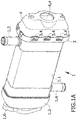
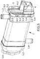
- a first embodiment of the invention is seen in Figure 1A by means of a perspective view of the heat exchanger.
- the heat exchanger of the embodiments that will be described is particularly suitable for cooling recirculated gas in an EGR system.
- the heat exchanger according to this embodiment has a main body (1) comprising a shell (1.1) which is configured as a tubular element having a rectangular section.
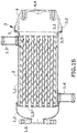
- Figure 1B shows a section view of the heat exchanger, where a first baffle (3) is shown at one end of the shell (1.1) and a second baffle (1.5) is shown at the opposite end.
- a bundle of heat exchange tubes (2) extending between the first baffle (3) and the second baffle (1.5) is housed inside the shell (1.1).
- the space left by the bundle of tubes (2) inside the shell (1.1) houses the liquid coolant circulating between an inlet and an outlet (1.3, 1.4) located at both ends of the shell (1.1).
- the inside of the manifold (4) is in fluid communication with the inside of the tubes of the bundle of tubes (2) such that the gas entering the manifold (4) passes to the interior of the bundle of tubes (2) to give off its heat.
- the outlet manifold (1.2) has a flange (1.6) at its outlet which allows coupling to the already cooled EGR gas conduit.
- manifold (4) the part that is attached by crimping with the main body (1) has been identified as manifold (4) because this identification takes into consideration its function, which is to establish fluid communication of the gas it receives with the inside of the bundle of tubes (2); nevertheless, according to other embodiments the manifold can be the main body of a flow rate management valve or any other element verifying the same function and on which the joint is established according to the first inventive aspect.
- An object of the invention is the joint between the manifold (4), in this case the intake manifold, and the main body (1) of the heat exchanger.
- this joint is done by means of a configuration of the main body (1) provided by one of its components, the first baffle (3).
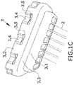
- the first baffle (3) shown mainly in Figure 1C and also in Figures 3 and 4 in section views and mounted in the exploded perspective view of Figure 2 , is a flat die cut and stamped plate. Perforations housing ends of the heat exchange tubes (2) are obtained by means of die cutting. These die cuts are on the essentially flat surface which is transverse to the heat exchange tubes (2).
- This flat surface is prolonged according to two segments parallel to the surface of the shell (1.1), a first segment (3.1) arranged snugly against the inner face of the shell (1.1) and a second segment (3.2) having a larger section extending so as to surround the manifold (4) in an area in the form of band adjacent to the perimetral edge (4.1) of the manifold (4) being supported on the main body (1).
- first segment (3.1) and the second segment (3.2) are shown in Figures 3 and 4 as being straight and parallel, connected by stepping (3.3) providing a seat for the manifold (4).
- Figure 2 shows the manifold (4) with a plurality of cavities (4.2) equally distributed in the peripheral area close to the perimetral edge (4.1), the one that establishes the seat on the main body (1), although spaced from same (4.1).
- Figures 4 and 5 show how the perimetral edge (4.1) is supported directly on the seat formed by the stepping (3.3) of the first baffle (3).
- the outer face of the perimetral edge (4.1) establishing the support on the stepping (3.3) shows a step (4.3) generating a recessed space in the form of a housing for an elastically deformable perimetral gasket (5).
- the elastically deformable perimetral gasket (5) is an elastic ring having a circular section.
- Compression of the elastically deformable perimetral gasket (5) is due to the pressure applied by surfaces of two rigid parts, the surface of the step (4.3) of the manifold (4) and the surface of the stepping (3.3) serving as a seat for said manifold (4). Given that the distance between these two surfaces (4.3, 3.3) is less than the dimensions of the perimetral gasket (5), the gasket (5) is subjected to compression. Since the perimetral edge (4.1) of the manifold is supported directly on the seat, the condition concerning the distance between the step (4.3) and the perimetral edge (4.1) of the manifold (4) results in an equivalent condition concerning the distance between the surfaces (4.3, 3.3) pressing against the elastically deformable perimetral gasket (5).
- the perimetral edge (4.1) of the manifold (4) is supported directly on the stepping (3.3), the distance between the step (4.3) and the perimetral edge (4.1) of the manifold (4) thereby does not depend on the degree of pressure between the manifold (4) and the main body (1) but rather on the dimensions of the step (4.3) of the manifold (4).
- the tolerances of this step (4.3) can be very precisely controlled during machining thereof, so the pressure on the perimetral gasket (5) or O-ring can be established without said gasket (5) sustaining significant variations derived from the production process.
- the cavity (4.2) of the manifold (4) has two essentially parallel side walls (4.2.1, 4.2.2) and a wall at the bottom (4.2.3) of the cavity (4.2) transverse to the walls, all of them attached by means of curved transition surfaces.
- the side wall (4.2.1) of the cavity (4.2) serving as a support in the joint i.e., the wall closest to the perimetral edge (4.1) of the manifold (4) seated in the stepping (3.3) of the first baffle (3), is important.
- FIG. 3 and 4 show the second segment (3.2) of the baffle (3) with a set of slots (3.5) giving rise to strips (3.4).
- the slots (3.5) are oriented parallel to the free edge of the second segment (3.2) of the first baffle (3), giving rise to strips (3.4) defined between two parallel free edges, the free edge of the second segment (3.2) of the baffle (3) and the edge generated by the slot (3.5), for example by means of die cutting.
- the strips (3.4) are flat segments which are located covering the cavity (4.2) with which they cooperate to establish the joint.
- the joint is established by pressing the strip (3.4) towards the inside of the cavity (4.2), giving rise to permanent deformation.
- Figure 1C shows in detail the baffle (3) with the deformed strips (3.4), where the deformed surface of the strip (3.4) is still parallel to the longitudinal direction in which the bundle of tubes (2) extends.
- This direction is the direction of compression of the joint and it is in the direction in which the strips (3.4) are capable of absorbing enormous stress.
- this direction is a direction perpendicular to the direction in which both deformation of the strip and any possible elastic recovery, minimizing the effect thereof, takes place.
- the joint between the baffle (3) and the shell (1.1) is preferably by means of brazing.
- Figures 3 and 5 show the second segment (3.2) of the first flat baffle (3) with the slots (3.5), and Figures 2 , 4 and 6 show the same second segment (3.2) with the resulting configuration after generating permanent deformations giving rise to the joint formed by crimping.
- Figure 4 shows the final position of the central portion of the strip (3.4) after deformation, establishing the support through the free edge generated by the slot (3.5) on the surface (4.2.1) of the cavity arranged closest to the perimetral edge (4.1) of the manifold (4).
- the surface (4.2.1) of the cavity (4.2) arranged closest to the perimetral edge (4.1) of the manifold (4) is the side wall closest to the perimetral edge (4.1) of the manifold (4).
- the side wall (4.2.1) closest to the perimetral edge (4.1) of the manifold (4) shows a slight inclination ( ⁇ ) such that the cavity (4.2) is slightly more open at the inlet than at the bottom of said cavity (4.2).
- Figure 1D shows the normal direction ( n ) of the side wall (4.2.1) serving as a support surface of the strip (3.4) with an inclination of an angle ⁇ with respect to the longitudinal direction of the heat exchanger. This angle is also seen in the tangent plotted on the curve defined by the section of the side wall (4.2.1) at the support point of the strip (3.4) and which is shown by means of a dotted line.
- This inclination ( ⁇ ) establishes a degree of wedging that increases the pressure force of the manifold (4) against the first baffle (3) through the seat formed by the stepping (3.3) the greater the deformation of the strip (3.4) towards the wall of the bottom (4.2.3) of the cavity (4.2).
- Figures 7 to 11 show a second embodiment with the same components as in the first embodiment except for those components directly linked with tightness between the manifold (4) and the main body (1). Therefore, the description of all the common elements is valid and for the sake of efficiency, only those changes in configuration related to the alternative solution for tightness are described below.
- Figure 7 shows an exploded view of the manifold (4) with respect to the main body (1) of the heat exchanger.
- the elastically deformable gasket (5) of the first embodiment has been replaced with a metal gasket (6).
- the manifold (4) does not have a stepping (4.3) for housing the gasket but rather the metal gasket (6) is placed such that it is interposed between the stepping (3.3) of the baffle (3) acting as a seat and the free edge (4.1) of the manifold (4).
- the metal gasket (6) has a discontinuous section such that when it is trapped between two parallel surfaces compressing it, it deforms until achieving a flat configuration. In this flat configuration, the metal gasket (6) no longer yields and starts to perform like a rigid solid.
- the metal gasket (6) thus configured requires a high attachment pressure. Nevertheless, it has been verified that the crimped joint according to the invention provides enough force, assuring proper air-tightness and dimensional stability.
- the metal gasket (6) thus configured is identified in this description as a gasket having limited compression given that, after compressing the gasket, causing deformation sufficient for achieving the flat configuration between the surfaces compressing it, the gasket does not further deform.
- the separation between the surfaces compressing the metal gasket (6) is essentially the thickness of the plate with which the metal gasket (6) has been configured.
- the condition of being a gasket having limited compression means that once this element (6) is compressed, it performs like a rigid solid, and therefore the support between the manifold (4) and the stepping (3.3) maintains the same dimensional stability with respect to the direct contact used in the first embodiment.
- Figures 10 and 11 show the process of attachment by deformation of the strips inside the cavities (4.2) in a way that is equivalent to the process shown in Figures 5 and 6 for the first embodiment.
- a preferred configuration establishes an equally distributed separation of the cavities (4.2) at least along the segments of each side of the prismatic configuration of the perimetral area along which the joint is established.
- the deformable strips (3.4) located in the segment (3.2) externally surrounding the manifold (4) at least by means of a band adjacent to its perimetral edge (4.1) can be configured such that they are stronger with a wider band such that the deformable strips (3.4) have a second, non-deformed strip adjacent to the deformable strip (3.4).
- the deformable strips (3.4) have been referred to as such because they are what are deformed after joint. After the joint they are deformed strips (3.4).
- One way of obtaining this second, non-deformed adjacent strip is by means of applying two slots parallel to one another and parallel to the free edge of the second segment (3.2), a first slot (3.5) for generating the free support edge with the inner surface (4.2.1) of the cavity (4.2) and a second slot to establish the separation between the deformable strip (3.4) and the non-deformed strip.
- This reinforced configuration obtained by means of two parallel slots is also applicable when the shell (1.1) of the main body (1) is what defines a seating step for the manifold (4) and the strips which allow the crimped joint with said manifold (4).
- Another object of the invention is the EGR system having a more compact and lighter configuration incorporating a heat exchanger configured according to any of the examples described.
Description
- The present invention is a heat exchanger, specifically a heat exchanger for EGR (Exhaust Gas Recirculation) systems mainly for reducing nitrogen oxide emission in internal combustion vehicles. The main application of this heat exchanger is to remove the heat from a hot gas, the recirculated gas, by means of a liquid coolant.
DE 10 2008 001 660 A1 discloses a heat exchanger as defined in the preamble ofclaim 1. - The invention is characterized by a particular crimped joint configuration between the manifold and the main body of the heat exchanger. To achieve the joint, the manifold comprises cavities distributed close to its perimetral edge, i.e., the edge that is coupled to the main body. The main body has a stepped seat on which the manifold is supported. Around the seat, the main body has a segment externally surrounding the manifold, at least in a band adjacent to its perimetral edge. This perimetral band has slots defining strips located between said slot and the free edge such that the strips, which are plastically deformed towards the inside of the cavities of the manifold, establish a joint with a very rigid and strong coupling force.
- The particular configuration of this joint allows for very short manufacturing times compared to the joints known today and the manufacturing tooling is less expensive.
FR 2 443 602 ADE 3419319 A1 andJP S55 143395 A - One of the fields of the art that has experienced the most intense development is the field of heat exchangers for EGR systems. The temperature of the recirculated gas taken from the exhaust gas reaches very high values. All the parts located in the segment of the EGR system before the heat exchanger are subjected to high temperatures. Particularly, the heat exchanger responsible for reducing the temperature of the recirculated gas has a joint between the manifold where the hot gas enters, and the heat exchanger which requires a very rigid, strong and reliable joint.
- One very reliable joint is the well-known joint based on the use of screws or bolts distributed around the perimeter around the area of the joint. The drawback of such joints is that the screw tightening operation requires the screw to be spaced from the body of the exchanger so that the tightening tool allows acting on the screw. The spacing of each screw with respect to the main body to be attached gives rise to bigger devices, hindering the packing capacity on the engine bay and raising the total weight of the device. Another drawback associated with this screwed solution is that the efficient manufacture of the exchanger requires one actuator for each screw in addition to other accessories such as tightening torque limiters. The price of each actuator is high, so the price of the tooling is as well, especially if there are many screws.
- An alternative to screwed joints is the use of crimped configurations or configurations formed by crimping. A crimped joint is understood as that joint between two parts by means of one or more securing elements, arranged in one of the parts, which are plastically deformed to establish the securing of the other part.
- There are joints formed by crimping between the main body of a heat exchanger and its manifold. In these joints formed by crimping, the manifold is supported on a seat of the main body of the heat exchanger with the intermediation of an elastically deformable gasket. The manifold has a perimetral rib cooperating with tabs of the main body. Once the manifold is placed on the seat formed by the elastically deformable gasket, the tabs of the main body plastically deform by means of tooling particularly configured for this purpose until getting the tab to be supported on the perimetral rib of the manifold such that both bodies, the manifold and the main body, are brought closer together. Bringing these two parts closer together gives rise to a compressive force on the elastically deformable gasket. Given that the tabs plastically deform, the joint is permanent.
- One of the drawbacks of this joint is that the plastic deformation of the tabs always entails a certain degree of elastic deformation. When the tooling imposes a certain degree of deformation, when the tooling is removed the tab recovers certain deformation and acquires an intermediate shape between the original shape and the shape imposed by the tooling. Although this degree of elastic recovery is small, the result is that the compression value of the elastically deformable gasket has a level of uncertainty that is hard to calculate during design.
- Additionally, the joint between both parts, the main body of the exchanger and the manifold, always has an elastically deformable gasket between both such that in the event of high stresses it enables modifying the relative position between both parts, jeopardizing air-tightness, especially if over time the elastically deformable gasket has experienced wear.
- The present invention provides a joint having the manufacturing advantages that a joint formed by crimping provides, but without the drawbacks identified above, i.e., under design conditions it allows establishing the degree of compression between the main body of the heat exchanger and the manifold with very low uncertainty, and the resulting joint is very rigid, maintaining air-tightness.
- The present invention is a heat exchanger, preferably a heat exchanger for cooling recirculated gas in an EGR system, in which the joint between the main body of said heat exchanger and the manifold is by means of a particular crimping configuration.
- When the heat exchanger is applied to cool hot recirculated gas in an EGR system, using the crimped joint according to the invention between the main body of the exchanger and the inlet manifold into the exchanger has particular advantage because this is the joint that is subjected to a higher temperature, and even in these more demanding conditions the joint according to the invention is capable of securely maintaining the joint.
- According to a first aspect of the invention, the present invention comprises the two parts to be attached to one another:
- a main body in turn comprising a shell, wherein
- said shell houses one or more heat exchange tubes for the passage of a first fluid, particularly a gas to be cooled, where the heat exchange tubes extend between two opposite ends of the shell;
- the shell comprises a space between the inner face of said shell and the heat exchange tubes for the passage of a second fluid, particularly a coolant fluid; and
- wherein the main body, in at least one of the ends of the shell, comprises a baffle such that the heat exchange tubes are attached to said baffle through one of the ends thereof; and
- a manifold in fluid communication with the inside of the heat exchange tubes attached to the baffle, this manifold being attached to the main body.
- The main body is the body of the heat exchanger where the bundle of exchange tubes is located and therefore where thermal energy is transferred from the gas to be cooled to the liquid coolant. The gas passes through the inside of the tubes of the bundle of tubes and the liquid coolant circulates around the outside of the tubes of the bundle of tubes and limited by the shell. Both fluids are separated such that heat is transferred from the hot gas to the liquid coolant through the wall of the exchange tubes.
- The preferred configuration of the heat exchanger is the configuration of a shell extending in the longitudinal direction determined by the bundle of heat exchange tubes housed therein. Although the invention requires the shell to have at one of its ends a baffle receiving one of the ends of each of the tubes of the bundle of tubes, the preferred configuration makes use of two baffles, one at each end of the shell and such that one baffle receives one end of the tubes of the bundle of tubes, and the other baffle, located on the opposite side of the shell, receives the opposite end of the tubes.
- The inner space demarcated by the inner wall of the shell, the heat exchange surface established by the exchange tubes and the baffle or baffles, is the space where the liquid coolant circulates. This space has inlet and outlet ports for the circulation of the liquid coolant.
- With respect to the gas to be cooled, said gas enters through a manifold, preferably the manifold to be attached by crimping to the main body of the exchanger, in order to access the inside of the heat exchange tubes. After the hot gas passes through the inside of the exchange tubes, giving off its heat, it exits into a second manifold which leads it to a conduit for later use. Although this second manifold has been identified as such, according to various embodiments it can be formed by parts of other components such as valves, giving rise to more compact configurations, for example.
- The baffle to which some of the ends of the heat exchange tubes are attached and which is located on the side of the main body of the heat exchanger where the joint formed by crimping is established is one of the elements which establishes the separation between the space of the liquid coolant and the gas such that the gas that is in the manifold to be attached to the main body of the heat exchanger is in fluid communication with the inside of the tubes attached to the baffle.
- The invention is additionally characterized in that:
- the manifold comprises a perimetral edge and a plurality of cavities on its outer face distributed around the perimeter and spaced from the perimetral edge,
- the main body is prolonged in a segment externally surrounding the manifold at least by means of a band adjacent to its perimetral edge wherein the main body comprises a stepping such that there is arranged a seat of the perimetral edge of the manifold on said stepping; and
- the segment of the main body externally surrounding the manifold comprises, coinciding with two or more cavities of the manifold and in each of such cavities, a strip configured between the edge of the segment of the main body externally surrounding the manifold and a slot spaced from said edge such that, the strip, by plastic deformation, enters the cavity of the manifold such that the free edge of the strip established by the slot is supported on the surface of the cavity arranged closest to the perimetral edge of the manifold.
- The main body has a step establishing the seat at the perimetral edge of the manifold. This seat establishes direct or indirect contact between the main body of the heat exchanger and the manifold. The manifold has one or more cavities distributed around its periphery serving as a support for the deformable element of the main body establishing the crimping according to the first aspect of the invention. The cavities are close to the perimetral edge of the manifold and spaced from it. In turn, the main body is prolonged according to a segment externally surrounding the manifold. The way in which it externally surrounds or goes around the manifold is by means of a band at least partially covering the perimetral edge of the manifold and particularly reaching the cavities of the manifold. If the band completely covers the perimetral edge of the manifold, rigidity is greater and the joint is also stronger.
- The segment of the main body reaching the cavities has a strip. The strip is defined between the edge of the segment externally surrounding the manifold and a slot spaced from the edge. The preferred configuration of the segment of the main body externally surrounding the manifold is, at least where the cavity is located, in the form of a band where the slot is preferably straight and parallel to the free edge of the band.
- The strip mainly extends in a perimetral direction and has two free edges, one which is the free edge of the perimetral band and the other one, which is located on the other side of the strip, defined by the slot. The slot can be made, for example, by die cutting and, as stated, gives rise to one of the free edges of the strip.
- Before the joint is established, the strip passes externally around the cavity. The joint is established by applying pressure from the outside on the strip, preferably in the central portion thereof, producing permanent deformation which makes the strip plastically deform towards the inside of the cavity. The position of the slot must be such that the free edge of the strip it generates makes contact with the inner surface of the cavity, being supported thereon in order to withstand the compressive stresses of the joint. In other words, the joint maintains compression through the support of the strip, plastically deformed towards the inside of the cavity, through its free edge generated by the slot, on the inner surface of the cavity.
- The normal direction of the inner surface of the cavity on which there is established the support of the plastically deformed strip is mainly oriented in the direction of compression between the main body of the exchanger and the manifold. If the seat between the main body of the exchanger and the manifold is contained in one plane, the normal direction of the inner surface of the cavity on which the plastically deformed strip is supported is mainly oriented in the direction perpendicular to said plane.
- In this case, it is said to be "mainly" oriented in the perpendicular direction because according to a preferred embodiment of the invention, the normal direction of the inner surface of the cavity on which the strip is supported is inclined with respect to the longitudinal direction of the body of the exchanger, with a small angle, giving rise to a wedging in the support of the strip. The inclination gives rise to a surface of the cavity in the support area favoring the adjustment of the degree of compression in the joint. The greater the deformation of the strip, i.e., it is imposed that said strip must further enter the cavity, the greater the compressive force said strip applies.
- Deformation of the strip is in the direction of entry into the cavity, whereas the supporting force of the strip on the inner surface of the cavity is in a direction that is essentially perpendicular to the direction in which deformation has taken place in order to achieve plastic deformation of the strip. The technical effect of this condition is that any elastic recovery of the strip when performing plastic deformation also takes place in a direction perpendicular to the direction of the joint, and therefore does not affect the compressive stress in the joint. Even if the surface where the support is established is inclined, the elastic recovery will have a very small component of its projection on the direction established by the compression in the joint, minimizing its effect.
- It has been indicated throughout this description that the seat of the manifold configured by means of a step is in the main body of the heat exchanger, and the same with respect to the segment surrounding or going around the manifold. Nevertheless, both the seat configured by means of a step and the segment surrounding or going around the manifold provided in the main body can be located in specific parts of said main body.
- Such parts are a first part where, according to a first embodiment, the seat is configured like a step and the segment it surrounds is the shell; and a second part where, according to a second embodiment, the seat is configured like a step and the segment it surrounds is the baffle receiving the ends of the bundle of tubes located on the side of the manifold where the joint is established. Given that this second embodiment has a more complex configuration, it is what will be used according to two configurations to explain the invention in detail.
- The first embodiment can be carried out, for example, by defining the seat or stepping for the manifold by means of an inward bend in the shell, leaving an expansion at the end of the shell corresponding to the band partially covering the manifold and where the strips are deformable.
- The second example, which will be described in further detail in reference to the drawings, has the advantage that the shell and the baffle can have different thicknesses. The shell has strength requirements different from those of the baffle and the joint. This configuration allows establishing the suitable thicknesses for each of the functions.
- These and other features and advantages of the invention will be better understood based on the following detailed description of a preferred embodiment, given solely by way of illustrative and non-limiting example, in reference to the attached drawings.
-
Figure 1A shows an outer perspective view of an embodiment of a heat exchanger according to the invention. -
Figure 1B shows the same device ofFigure 1A in an elevational view sectioned by the midplane parallel to the longitudinal direction determined by the bundle of tubes. -
Figure 1C shows a perspective view of a detail of the baffle according to any of the examples that will be shown below based on the joint with the manifold through said baffle. -
Figure 1D shows a section in the support region of the manifold on the seat defined by the baffle, as well as the specific manner in which the joint force is assured by means of crimping. -
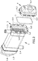
Figure 2 shows an exploded perspective view of the same embodiment shown inFigures 1A and1B wherein tightness is achieved with an elastically deformable gasket. -
Figure 3 shows a section of the same embodiment according to a plane parallel to the longitudinal direction determined by the exchange tubes and in a central position coinciding with two cavities where the joint formed by crimping is established. The drawing corresponds to the configuration of the strips before carrying out the deformation establishing the joint. -
Figure 4 shows the same section as in the preceding drawing wherein the strips have already been deformed to establish the joint between the main body of the heat exchanger and the manifold. -
Figures 5 and6 show a perspective view such as that ofFigure 1A , before and after performing deformation of the strips, where the manifold has been sectioned in half by means of a plane parallel to the longitudinal direction determined by the exchange tubes and in a central position coinciding with two cavities wherein the joint formed by crimping is established, where this section allows observing the inside of the manifold and details of the joint. -
Figure 7 shows an exploded perspective view of a second embodiment where tightness is achieved with a metal gasket initially allowing a pre-established degree of deformation but which, once that pre-established deformation has been surpassed, performs in a rigid manner. -
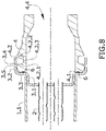
Figure 8 shows a section of the same second embodiment according to a plane parallel to the longitudinal direction determined by the exchange tubes and in a central position coinciding with two cavities wherein the joint formed by crimping is established. The drawing corresponds to the configuration of the strips before performing the deformation establishing the joint. -
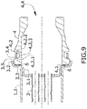
Figure 9 shows the same section as in the preceding drawing, wherein the strips have already been deformed to establish the joint between the main body of the heat exchanger and the manifold. -
Figures 10 and11 show a perspective view of the second embodiment, before and after performing deformation of the strips, wherein the manifold has been sectioned in half by means of a plane parallel to the longitudinal direction determined by the exchange tubes and in a central position coinciding with two cavities where the joint formed by crimping is established, wherein this section allows observing the inside of the manifold and details of the joint. - According to the first inventive aspect, the present invention relates to a device for heat exchange, wherein the main body of the heat exchanger and at least one of its manifolds are attached by a specific joint formed by crimping.
- A first embodiment of the invention is seen in
Figure 1A by means of a perspective view of the heat exchanger. The heat exchanger of the embodiments that will be described is particularly suitable for cooling recirculated gas in an EGR system. - The heat exchanger according to this embodiment has a main body (1) comprising a shell (1.1) which is configured as a tubular element having a rectangular section.
-
Figure 1B shows a section view of the heat exchanger, where a first baffle (3) is shown at one end of the shell (1.1) and a second baffle (1.5) is shown at the opposite end. - A bundle of heat exchange tubes (2) extending between the first baffle (3) and the second baffle (1.5) is housed inside the shell (1.1). The space left by the bundle of tubes (2) inside the shell (1.1) houses the liquid coolant circulating between an inlet and an outlet (1.3, 1.4) located at both ends of the shell (1.1).
- Hot gas enters through an inlet (4.4) of a manifold (4) which is manufactured by molding in this embodiment. The inside of the manifold (4) is in fluid communication with the inside of the tubes of the bundle of tubes (2) such that the gas entering the manifold (4) passes to the interior of the bundle of tubes (2) to give off its heat. After getting past the bundle of tubes (2), the gas exits, reaching the inner space of an outlet manifold (1.2), manufactured in stamped sheet metal in this embodiment. As shown in
Figure 1B , the outlet manifold (1.2) has a flange (1.6) at its outlet which allows coupling to the already cooled EGR gas conduit. - Throughout this description, the part that is attached by crimping with the main body (1) has been identified as manifold (4) because this identification takes into consideration its function, which is to establish fluid communication of the gas it receives with the inside of the bundle of tubes (2); nevertheless, according to other embodiments the manifold can be the main body of a flow rate management valve or any other element verifying the same function and on which the joint is established according to the first inventive aspect.
- An object of the invention is the joint between the manifold (4), in this case the intake manifold, and the main body (1) of the heat exchanger. In this embodiment, this joint is done by means of a configuration of the main body (1) provided by one of its components, the first baffle (3).
- The first baffle (3), shown mainly in
Figure 1C and also inFigures 3 and4 in section views and mounted in the exploded perspective view ofFigure 2 , is a flat die cut and stamped plate. Perforations housing ends of the heat exchange tubes (2) are obtained by means of die cutting. These die cuts are on the essentially flat surface which is transverse to the heat exchange tubes (2). - This flat surface is prolonged according to two segments parallel to the surface of the shell (1.1), a first segment (3.1) arranged snugly against the inner face of the shell (1.1) and a second segment (3.2) having a larger section extending so as to surround the manifold (4) in an area in the form of band adjacent to the perimetral edge (4.1) of the manifold (4) being supported on the main body (1).
- In section views, the first segment (3.1) and the second segment (3.2) are shown in
Figures 3 and4 as being straight and parallel, connected by stepping (3.3) providing a seat for the manifold (4). - The section view of
Figure 3 and the perspective view ofFigure 5 show the configuration of the first baffle (3) before establishing the joint. -
Figure 2 shows the manifold (4) with a plurality of cavities (4.2) equally distributed in the peripheral area close to the perimetral edge (4.1), the one that establishes the seat on the main body (1), although spaced from same (4.1). -
Figures 4 and5 , and mainly in the enlarged view of the joint shown inFigure 1D , show how the perimetral edge (4.1) is supported directly on the seat formed by the stepping (3.3) of the first baffle (3). The outer face of the perimetral edge (4.1) establishing the support on the stepping (3.3) shows a step (4.3) generating a recessed space in the form of a housing for an elastically deformable perimetral gasket (5). In this embodiment, the elastically deformable perimetral gasket (5) is an elastic ring having a circular section. - Compression of the elastically deformable perimetral gasket (5) is due to the pressure applied by surfaces of two rigid parts, the surface of the step (4.3) of the manifold (4) and the surface of the stepping (3.3) serving as a seat for said manifold (4). Given that the distance between these two surfaces (4.3, 3.3) is less than the dimensions of the perimetral gasket (5), the gasket (5) is subjected to compression. Since the perimetral edge (4.1) of the manifold is supported directly on the seat, the condition concerning the distance between the step (4.3) and the perimetral edge (4.1) of the manifold (4) results in an equivalent condition concerning the distance between the surfaces (4.3, 3.3) pressing against the elastically deformable perimetral gasket (5).
- The perimetral edge (4.1) of the manifold (4) is supported directly on the stepping (3.3), the distance between the step (4.3) and the perimetral edge (4.1) of the manifold (4) thereby does not depend on the degree of pressure between the manifold (4) and the main body (1) but rather on the dimensions of the step (4.3) of the manifold (4). The tolerances of this step (4.3) can be very precisely controlled during machining thereof, so the pressure on the perimetral gasket (5) or O-ring can be established without said gasket (5) sustaining significant variations derived from the production process.
- In this embodiment it can be seen how the cavity (4.2) of the manifold (4) has two essentially parallel side walls (4.2.1, 4.2.2) and a wall at the bottom (4.2.3) of the cavity (4.2) transverse to the walls, all of them attached by means of curved transition surfaces.
- The side wall (4.2.1) of the cavity (4.2) serving as a support in the joint, i.e., the wall closest to the perimetral edge (4.1) of the manifold (4) seated in the stepping (3.3) of the first baffle (3), is important.
- The section views of
Figures 3 and4 and the perspective view ofFigure 2 show the second segment (3.2) of the baffle (3) with a set of slots (3.5) giving rise to strips (3.4). The slots (3.5) are oriented parallel to the free edge of the second segment (3.2) of the first baffle (3), giving rise to strips (3.4) defined between two parallel free edges, the free edge of the second segment (3.2) of the baffle (3) and the edge generated by the slot (3.5), for example by means of die cutting. - Before deformation, the strips (3.4) are flat segments which are located covering the cavity (4.2) with which they cooperate to establish the joint. The joint is established by pressing the strip (3.4) towards the inside of the cavity (4.2), giving rise to permanent deformation.
-
Figure 1C shows in detail the baffle (3) with the deformed strips (3.4), where the deformed surface of the strip (3.4) is still parallel to the longitudinal direction in which the bundle of tubes (2) extends. This direction is the direction of compression of the joint and it is in the direction in which the strips (3.4) are capable of absorbing enormous stress. Likewise, this direction is a direction perpendicular to the direction in which both deformation of the strip and any possible elastic recovery, minimizing the effect thereof, takes place. - The joint between the baffle (3) and the shell (1.1) is preferably by means of brazing.
-
Figures 3 and5 show the second segment (3.2) of the first flat baffle (3) with the slots (3.5), andFigures 2 ,4 and6 show the same second segment (3.2) with the resulting configuration after generating permanent deformations giving rise to the joint formed by crimping. - Particularly,
Figure 4 shows the final position of the central portion of the strip (3.4) after deformation, establishing the support through the free edge generated by the slot (3.5) on the surface (4.2.1) of the cavity arranged closest to the perimetral edge (4.1) of the manifold (4). In this particular case, the surface (4.2.1) of the cavity (4.2) arranged closest to the perimetral edge (4.1) of the manifold (4) is the side wall closest to the perimetral edge (4.1) of the manifold (4). - In this embodiment, the side wall (4.2.1) closest to the perimetral edge (4.1) of the manifold (4) shows a slight inclination (α) such that the cavity (4.2) is slightly more open at the inlet than at the bottom of said cavity (4.2).
Figure 1D shows the normal direction (n ) of the side wall (4.2.1) serving as a support surface of the strip (3.4) with an inclination of an angle α with respect to the longitudinal direction of the heat exchanger. This angle is also seen in the tangent plotted on the curve defined by the section of the side wall (4.2.1) at the support point of the strip (3.4) and which is shown by means of a dotted line. - This inclination (α) establishes a degree of wedging that increases the pressure force of the manifold (4) against the first baffle (3) through the seat formed by the stepping (3.3) the greater the deformation of the strip (3.4) towards the wall of the bottom (4.2.3) of the cavity (4.2).
-
Figures 7 to 11 show a second embodiment with the same components as in the first embodiment except for those components directly linked with tightness between the manifold (4) and the main body (1). Therefore, the description of all the common elements is valid and for the sake of efficiency, only those changes in configuration related to the alternative solution for tightness are described below. -
Figure 7 shows an exploded view of the manifold (4) with respect to the main body (1) of the heat exchanger. In this perspective view, it can be seen that the elastically deformable gasket (5) of the first embodiment has been replaced with a metal gasket (6). In this case, the manifold (4) does not have a stepping (4.3) for housing the gasket but rather the metal gasket (6) is placed such that it is interposed between the stepping (3.3) of the baffle (3) acting as a seat and the free edge (4.1) of the manifold (4). - The metal gasket (6) has a discontinuous section such that when it is trapped between two parallel surfaces compressing it, it deforms until achieving a flat configuration. In this flat configuration, the metal gasket (6) no longer yields and starts to perform like a rigid solid. The metal gasket (6) thus configured requires a high attachment pressure. Nevertheless, it has been verified that the crimped joint according to the invention provides enough force, assuring proper air-tightness and dimensional stability.
- The metal gasket (6) thus configured is identified in this description as a gasket having limited compression given that, after compressing the gasket, causing deformation sufficient for achieving the flat configuration between the surfaces compressing it, the gasket does not further deform. In this configuration, the separation between the surfaces compressing the metal gasket (6) is essentially the thickness of the plate with which the metal gasket (6) has been configured. The condition of being a gasket having limited compression means that once this element (6) is compressed, it performs like a rigid solid, and therefore the support between the manifold (4) and the stepping (3.3) maintains the same dimensional stability with respect to the direct contact used in the first embodiment.
-
Figures 10 and11 show the process of attachment by deformation of the strips inside the cavities (4.2) in a way that is equivalent to the process shown inFigures 5 and6 for the first embodiment. - A preferred configuration establishes an equally distributed separation of the cavities (4.2) at least along the segments of each side of the prismatic configuration of the perimetral area along which the joint is established.
- In any of the embodiments, the deformable strips (3.4) located in the segment (3.2) externally surrounding the manifold (4) at least by means of a band adjacent to its perimetral edge (4.1) can be configured such that they are stronger with a wider band such that the deformable strips (3.4) have a second, non-deformed strip adjacent to the deformable strip (3.4). The deformable strips (3.4) have been referred to as such because they are what are deformed after joint. After the joint they are deformed strips (3.4).
- One way of obtaining this second, non-deformed adjacent strip is by means of applying two slots parallel to one another and parallel to the free edge of the second segment (3.2), a first slot (3.5) for generating the free support edge with the inner surface (4.2.1) of the cavity (4.2) and a second slot to establish the separation between the deformable strip (3.4) and the non-deformed strip.
- This reinforced configuration obtained by means of two parallel slots is also applicable when the shell (1.1) of the main body (1) is what defines a seating step for the manifold (4) and the strips which allow the crimped joint with said manifold (4).
- Another object of the invention is the EGR system having a more compact and lighter configuration incorporating a heat exchanger configured according to any of the examples described.
Claims (10)
- A heat exchanger comprising:- a main body (1) in turn comprising a shell (1.1), whereinsaid shell (1.1) houses one or more heat exchange tubes (2) for the passage of a first fluid, particularly a gas to be cooled, where the heat exchange tubes (2) extend between two opposite ends of the shell (1.1);the shell (1.1) comprises a space between the inner face of said shell (1.1) and the heat exchange tubes (2) for the passage of a second fluid, particularly a coolant fluid; andwherein the main body (1), in at least one of the ends of the shell (1.1), comprises a baffle (3) such that the heat exchange tubes (2) are attached to said baffle (3) through one of the ends thereof,- a manifold (4) in fluid communication with the inside of the heat exchange tubes (2) attached to the baffle (3), this manifold (4) being attached to the main body (1),characterized in that:- the manifold (4) comprises a perimetral edge (4.1) and a plurality of cavities (4.2) on its outer face distributed around the perimeter and spaced from the perimetral edge (4.1),- the main body (1) is prolonged in a segment (3.2) externally surrounding the manifold (4) at least by means of a band adjacent to its perimetral edge (4.1) wherein the main body (1) comprises a stepping (3.3) such that there is arranged a seat of the perimetral edge (4.1) of the manifold (4) on said stepping (3.3); and- the segment (3.2) of the main body (1) externally surrounding the manifold (4) comprises, coinciding with two or more cavities (4.2) of the manifold (4) and in each of such cavities (4.2), a strip (3.4) configured between the edge of the segment (3.2) of the main body (1) externally surrounding the manifold (4) and a slot (3.5) spaced from said edge such that by plastic deformation, the strip (3.4) enters the cavity (4.2) of the manifold (4) such that the free edge of the strip (3.4) established by the slot (3.5) is supported on the surface (4.2.1) of the cavity (4.2) arranged closest to the perimetral edge (4.1) of the manifold (4).
- The heat exchanger according to claim 1, wherein the baffle (3) of the main body (1) extends, around the perimeter thereof, towards the manifold (4) according to two consecutive segments:- a first segment (3.1) of said baffle (3) being supported on the inner face of either the shell (1.1) or of the main body (1), and a second segment (3.2) of the baffle (3) giving rise to the segment of the main body (1) externally surrounding the manifold (4), extending at least by means of a band adjacent to its perimetral edge (4.1); and wherein,- between the first segment (3.1) and the second segment (3.2), the baffle (3) comprises a transition configured according to stepping (3.3), this stepping (3.3) being the stepping of the main body (1) establishing support for the perimetral edge (4.1) of the manifold (4).
- The heat exchanger according to any of the preceding claims, wherein the surface of the cavity (4.2) of the manifold (4) on which the strip (3.4) is supported is inclined (α) such that the greater the deformation of the strip (3.4) towards the inside of the cavity (4.2), the greater the compression between the manifold (4) and the baffle (3).
- The heat exchanger according to any of the preceding claims, wherein- the perimetral edge (4.1) of the manifold (4) is supported directly on the stepping (3.3); and- the perimetral edge (4.1) of the manifold (4) has a step (4.3) giving rise to a housing which houses an elastically deformable perimetral gasket (5), where the distance between the step (4.3) and the perimetral edge (4.1) of the manifold (4) is less than the dimensions of the perimetral gasket (5).
- The heat exchanger according to any of claims 1 to 4, wherein the perimetral edge (4.1) of the manifold (4) is supported on the stepping (3.3) with the interposition of a metal gasket (6) having limited compression, i.e., such that after a predetermined compression value the metal gasket performs like a rigid gasket.
- The heat exchanger according to claim 5, wherein the metal gasket (6) having limited compression has a discontinuous and/or stepped section.
- The heat exchanger according to any of the preceding claims, wherein the cavities (4.2) of the manifold (4) are equally distributed around the perimetral edge (4.1) of the manifold (4).
- The heat exchanger according to any of the preceding claims, wherein the baffle (3) is made of die-cut and stamped sheet metal.
- The heat exchanger according to any of the preceding claims, wherein the joint between the baffle (3) and either the shell (1) or the main body, is by means of brazing.
- An EGR system comprising a heat exchanger according to any of the preceding claims.
Priority Applications (4)
| Application Number | Priority Date | Filing Date | Title |
|---|---|---|---|
| EP15382321.6A EP3106821B1 (en) | 2015-06-18 | 2015-06-18 | Heat exchanger |
| CN201610422094.0A CN106257038B (en) | 2015-06-18 | 2016-06-15 | Heat exchanger |
| KR1020160075061A KR20160150030A (en) | 2015-06-18 | 2016-06-16 | Heat exchanger |
| US15/186,021 US20160370131A1 (en) | 2015-06-18 | 2016-06-17 | Heat exchanger |
Applications Claiming Priority (1)
| Application Number | Priority Date | Filing Date | Title |
|---|---|---|---|
| EP15382321.6A EP3106821B1 (en) | 2015-06-18 | 2015-06-18 | Heat exchanger |
Publications (2)
| Publication Number | Publication Date |
|---|---|
| EP3106821A1 EP3106821A1 (en) | 2016-12-21 |
| EP3106821B1 true EP3106821B1 (en) | 2019-05-15 |
Family
ID=54011675
Family Applications (1)
| Application Number | Title | Priority Date | Filing Date |
|---|---|---|---|
| EP15382321.6A Not-in-force EP3106821B1 (en) | 2015-06-18 | 2015-06-18 | Heat exchanger |
Country Status (4)
| Country | Link |
|---|---|
| US (1) | US20160370131A1 (en) |
| EP (1) | EP3106821B1 (en) |
| KR (1) | KR20160150030A (en) |
| CN (1) | CN106257038B (en) |
Families Citing this family (18)
| Publication number | Priority date | Publication date | Assignee | Title |
|---|---|---|---|---|
| WO2017032405A1 (en) * | 2015-08-24 | 2017-03-02 | Mahle International Gmbh | Heat exchanger |
| JP6551293B2 (en) * | 2016-04-20 | 2019-07-31 | 株式会社デンソー | Heat exchanger |
| KR102123452B1 (en) * | 2017-02-24 | 2020-06-16 | 한온시스템 주식회사 | EGR cooler for Motor Vehicle |
| CN106855367B (en) * | 2017-02-28 | 2024-01-26 | 郑州大学 | Shell-and-tube heat exchanger with distributed inlets and outlets |
| CN106679467B (en) * | 2017-02-28 | 2019-04-05 | 郑州大学 | Shell-and-tube heat exchanger with external bobbin carriage |
| EP3454001B1 (en) * | 2017-09-06 | 2020-05-06 | Borgwarner Emissions Systems Spain, S.L.U. | Compact heat exchanger |
| JP6841196B2 (en) * | 2017-09-27 | 2021-03-10 | 株式会社デンソー | Heat exchanger and its manufacturing method |
| JP7010715B2 (en) * | 2018-01-29 | 2022-02-10 | 株式会社ティラド | Connection structure of heat exchanger tank |
| CN112105515B (en) * | 2018-03-23 | 2023-10-24 | 摩丁制造公司 | High pressure tolerant liquid-to-refrigerant heat exchanger |
| DE102018109233A1 (en) * | 2018-04-18 | 2019-10-24 | Hanon Systems | System for connecting housing elements of a device for heat transfer |
| JP2019190754A (en) * | 2018-04-26 | 2019-10-31 | 株式会社デンソー | Heat exchanger |
| DE102018211807A1 (en) * | 2018-07-16 | 2020-01-16 | Mahle International Gmbh | Exhaust gas recirculation arrangement for an internal combustion engine |
| JP7230502B2 (en) * | 2018-12-27 | 2023-03-01 | 株式会社デンソー | Heat exchanger |
| EP3786563A1 (en) * | 2019-08-26 | 2021-03-03 | Valeo Termico S.A. | A connection system |
| GB2588636B8 (en) * | 2019-10-30 | 2023-08-30 | Denso Marston Ltd | A heat exchanger |
| EP3828406A1 (en) * | 2019-11-29 | 2021-06-02 | Borgwarner Emissions Systems Spain, S.L.U. | Heat exchanger device for egr systems |
| CN112949040B (en) * | 2021-02-01 | 2022-10-14 | 山东大学 | Cylinder cover assembly torque threshold big data determination method influencing emission consistency |
| FR3139892A1 (en) * | 2022-09-16 | 2024-03-22 | L'air Liquide, Societe Anonyme Pour L'etude Et L'exploitation Des Procedes Georges Claude | Tube-and-shell heat exchanger |
Family Cites Families (21)
| Publication number | Priority date | Publication date | Assignee | Title |
|---|---|---|---|---|
| DE2852408B2 (en) * | 1978-12-04 | 1981-10-01 | Süddeutsche Kühlerfabrik Julius Fr. Behr GmbH & Co KG, 7000 Stuttgart | Clamp connection |
| JPS55143395A (en) * | 1979-04-24 | 1980-11-08 | Nippon Radiator Co Ltd | Tank for heat exchange |
| GB2138335B (en) * | 1983-04-19 | 1986-05-14 | Ford Motor Co | An assembly of two parts |
| DE3419319A1 (en) * | 1984-05-24 | 1985-11-28 | Erich 2210 Itzehoe Jabusch | Method for mounting plastic radiator tanks and radiator grids by means of a high-speed cutter |
| US4600051A (en) * | 1984-07-13 | 1986-07-15 | Modine Manufacturing | Tank-header plate connection |
| DE3732964A1 (en) * | 1987-09-30 | 1989-04-13 | Sueddeutsche Kuehler Behr | TERMINAL CONNECTION |
| US5311933A (en) * | 1993-01-21 | 1994-05-17 | Lee Lanny R | Connection of tank to core for heat exchanger |
| JP2001304047A (en) * | 2000-04-24 | 2001-10-31 | Usui Internatl Ind Co Ltd | Egr gas cooling device |
| DE10233407B4 (en) * | 2001-07-26 | 2016-02-18 | Denso Corporation | Exhaust gas heat exchanger |
| US7004751B2 (en) * | 2003-12-23 | 2006-02-28 | Jotul North America, Inc. | Gas burner assemblies, methods for assembling, and gas fired appliances employing same |
| FR2868522B1 (en) * | 2004-03-30 | 2007-06-01 | Valeo Thermique Moteur Sas | HEAT EXCHANGE MODULE, ESPECIALLY FOR MOTOR VEHICLES |
| KR100649597B1 (en) * | 2004-12-10 | 2006-11-28 | 엘지전자 주식회사 | Exhaust gas heat exchanger for cogeneration system |
| US7708842B2 (en) * | 2006-08-18 | 2010-05-04 | Federal-Mogul World Wide, Inc. | Metal gasket |
| CN101688763B (en) * | 2007-04-11 | 2014-08-20 | 贝洱两合公司 | Heat exchanger |
| DE102008001660A1 (en) * | 2007-07-11 | 2009-01-15 | Visteon Global Technologies, Inc., Van Buren Township | Lightweight flow heat exchanger |
| DE102007040793A1 (en) * | 2007-08-28 | 2009-03-05 | Behr Gmbh & Co. Kg | heat exchangers |
| FR2954481B1 (en) * | 2009-12-18 | 2012-02-03 | Valeo Systemes Thermiques | HEAT EXCHANGER |
| DE102010015782A1 (en) * | 2010-04-20 | 2011-10-20 | Benteler Automobiltechnik Gmbh | Heat exchanger pipe, particularly for recycling of exhaust gases radiator, has tubing body with impression that is arranged in longitudinal direction with distance |
| DE102012004926A1 (en) * | 2012-03-10 | 2013-09-12 | Volkswagen Aktiengesellschaft | Heat exchanger with a tubesheet and a dedicated tube plate |
| DE102012206982A1 (en) * | 2012-04-26 | 2013-10-31 | Behr Gmbh & Co. Kg | Heat exchanger |
| US20150300745A1 (en) * | 2014-04-16 | 2015-10-22 | Enterex America LLC | Counterflow helical heat exchanger |
-
2015
- 2015-06-18 EP EP15382321.6A patent/EP3106821B1/en not_active Not-in-force
-
2016
- 2016-06-15 CN CN201610422094.0A patent/CN106257038B/en not_active Expired - Fee Related
- 2016-06-16 KR KR1020160075061A patent/KR20160150030A/en unknown
- 2016-06-17 US US15/186,021 patent/US20160370131A1/en not_active Abandoned
Also Published As
| Publication number | Publication date |
|---|---|
| KR20160150030A (en) | 2016-12-28 |
| EP3106821A1 (en) | 2016-12-21 |
| US20160370131A1 (en) | 2016-12-22 |
| CN106257038B (en) | 2019-06-28 |
| CN106257038A (en) | 2016-12-28 |
Similar Documents
| Publication | Publication Date | Title |
|---|---|---|
| EP3106821B1 (en) | Heat exchanger | |
| EP3161403B1 (en) | Heat exchanger with reinforced header plate | |
| US10337801B2 (en) | Heat exchanger for cooling a flow of charge air, and method of assembling the same | |
| US9175596B2 (en) | Intake pipe having an integrated intercooler | |
| US8910704B2 (en) | Heat exchanger | |
| US6533027B2 (en) | Device for assembling at least one item of equipment onto a heat exchanger | |
| US10955197B2 (en) | Structurally integral heat exchanger within a plastic housing | |
| CN109844441B (en) | Heat exchanger having a bypass seal with a retaining clip | |
| US20090260775A1 (en) | Heat exchanger, in particular an exhaust gas evaporator of a motor vehicle | |
| KR20010085507A (en) | Heat-exchange module, especially for a motor vehicle | |
| JP6183617B2 (en) | Heat exchangers, especially charge air coolers | |
| US5390733A (en) | Heat exchanger manifold assembly | |
| EP3290848B1 (en) | Header for a heat exchanger, and method of making the same | |
| CN111094887A (en) | Heat exchanger, in particular for the thermal conditioning of batteries, and corresponding production method | |
| JP2006005014A (en) | Stacked cooler | |
| US20150129186A1 (en) | Heat Exchanger Having A Reinforced Collector | |
| CN110953060A (en) | Heat exchanger | |
| CN110388844B (en) | System for connecting housing elements of a device for heat conduction | |
| US20200119413A1 (en) | Device for cooling batteries and associated production method | |
| US20160214457A1 (en) | Heat exchanger for exchanging heat between a heat-transfer liquid and a refrigerant, in particular for a motor vehicle | |
| CN112033184A (en) | Heat exchanger and method for manufacturing the same | |
| EP4317858A1 (en) | Refrigerant module for thermal management system | |
| JPH11304378A (en) | Heat exchanger for vehicle | |
| KR20180005397A (en) | Heat exchanger and method of fixing bracket thereof | |
| JPH05322475A (en) | Charged air cooler and manufacture thereof |
Legal Events
| Date | Code | Title | Description |
|---|---|---|---|
| PUAI | Public reference made under article 153(3) epc to a published international application that has entered the european phase |
Free format text: ORIGINAL CODE: 0009012 |
|
| STAA | Information on the status of an ep patent application or granted ep patent |
Free format text: STATUS: THE APPLICATION HAS BEEN PUBLISHED |
|
| AK | Designated contracting states |
Kind code of ref document: A1 Designated state(s): AL AT BE BG CH CY CZ DE DK EE ES FI FR GB GR HR HU IE IS IT LI LT LU LV MC MK MT NL NO PL PT RO RS SE SI SK SM TR |
|
| AX | Request for extension of the european patent |
Extension state: BA ME |
|
| STAA | Information on the status of an ep patent application or granted ep patent |
Free format text: STATUS: REQUEST FOR EXAMINATION WAS MADE |
|
| 17P | Request for examination filed |
Effective date: 20170620 |
|
| RBV | Designated contracting states (corrected) |
Designated state(s): AL AT BE BG CH CY CZ DE DK EE ES FI FR GB GR HR HU IE IS IT LI LT LU LV MC MK MT NL NO PL PT RO RS SE SI SK SM TR |
|
| GRAP | Despatch of communication of intention to grant a patent |
Free format text: ORIGINAL CODE: EPIDOSNIGR1 |
|
| STAA | Information on the status of an ep patent application or granted ep patent |
Free format text: STATUS: GRANT OF PATENT IS INTENDED |
|
| RIC1 | Information provided on ipc code assigned before grant |
Ipc: F28F 1/06 20060101ALI20181119BHEP Ipc: F28F 1/08 20060101ALI20181119BHEP Ipc: F28D 7/16 20060101ALI20181119BHEP Ipc: F28F 9/02 20060101AFI20181119BHEP |
|
| INTG | Intention to grant announced |
Effective date: 20181207 |
|
| GRAS | Grant fee paid |
Free format text: ORIGINAL CODE: EPIDOSNIGR3 |
|
| GRAA | (expected) grant |
Free format text: ORIGINAL CODE: 0009210 |
|
| STAA | Information on the status of an ep patent application or granted ep patent |
Free format text: STATUS: THE PATENT HAS BEEN GRANTED |
|
| AK | Designated contracting states |
Kind code of ref document: B1 Designated state(s): AL AT BE BG CH CY CZ DE DK EE ES FI FR GB GR HR HU IE IS IT LI LT LU LV MC MK MT NL NO PL PT RO RS SE SI SK SM TR |
|
| REG | Reference to a national code |
Ref country code: CH Ref legal event code: EP |
|
| REG | Reference to a national code |
Ref country code: DE Ref legal event code: R096 Ref document number: 602015030291 Country of ref document: DE |
|
| REG | Reference to a national code |
Ref country code: IE Ref legal event code: FG4D |
|
| REG | Reference to a national code |
Ref country code: NL Ref legal event code: MP Effective date: 20190515 |
|
| REG | Reference to a national code |
Ref country code: LT Ref legal event code: MG4D |
|
| PG25 | Lapsed in a contracting state [announced via postgrant information from national office to epo] |
Ref country code: AL Free format text: LAPSE BECAUSE OF FAILURE TO SUBMIT A TRANSLATION OF THE DESCRIPTION OR TO PAY THE FEE WITHIN THE PRESCRIBED TIME-LIMIT Effective date: 20190515 Ref country code: ES Free format text: LAPSE BECAUSE OF FAILURE TO SUBMIT A TRANSLATION OF THE DESCRIPTION OR TO PAY THE FEE WITHIN THE PRESCRIBED TIME-LIMIT Effective date: 20190515 Ref country code: NL Free format text: LAPSE BECAUSE OF FAILURE TO SUBMIT A TRANSLATION OF THE DESCRIPTION OR TO PAY THE FEE WITHIN THE PRESCRIBED TIME-LIMIT Effective date: 20190515 Ref country code: FI Free format text: LAPSE BECAUSE OF FAILURE TO SUBMIT A TRANSLATION OF THE DESCRIPTION OR TO PAY THE FEE WITHIN THE PRESCRIBED TIME-LIMIT Effective date: 20190515 Ref country code: LT Free format text: LAPSE BECAUSE OF FAILURE TO SUBMIT A TRANSLATION OF THE DESCRIPTION OR TO PAY THE FEE WITHIN THE PRESCRIBED TIME-LIMIT Effective date: 20190515 Ref country code: SE Free format text: LAPSE BECAUSE OF FAILURE TO SUBMIT A TRANSLATION OF THE DESCRIPTION OR TO PAY THE FEE WITHIN THE PRESCRIBED TIME-LIMIT Effective date: 20190515 Ref country code: HR Free format text: LAPSE BECAUSE OF FAILURE TO SUBMIT A TRANSLATION OF THE DESCRIPTION OR TO PAY THE FEE WITHIN THE PRESCRIBED TIME-LIMIT Effective date: 20190515 Ref country code: PT Free format text: LAPSE BECAUSE OF FAILURE TO SUBMIT A TRANSLATION OF THE DESCRIPTION OR TO PAY THE FEE WITHIN THE PRESCRIBED TIME-LIMIT Effective date: 20190915 Ref country code: NO Free format text: LAPSE BECAUSE OF FAILURE TO SUBMIT A TRANSLATION OF THE DESCRIPTION OR TO PAY THE FEE WITHIN THE PRESCRIBED TIME-LIMIT Effective date: 20190815 |
|
| PG25 | Lapsed in a contracting state [announced via postgrant information from national office to epo] |
Ref country code: RS Free format text: LAPSE BECAUSE OF FAILURE TO SUBMIT A TRANSLATION OF THE DESCRIPTION OR TO PAY THE FEE WITHIN THE PRESCRIBED TIME-LIMIT Effective date: 20190515 Ref country code: LV Free format text: LAPSE BECAUSE OF FAILURE TO SUBMIT A TRANSLATION OF THE DESCRIPTION OR TO PAY THE FEE WITHIN THE PRESCRIBED TIME-LIMIT Effective date: 20190515 Ref country code: BG Free format text: LAPSE BECAUSE OF FAILURE TO SUBMIT A TRANSLATION OF THE DESCRIPTION OR TO PAY THE FEE WITHIN THE PRESCRIBED TIME-LIMIT Effective date: 20190815 |
|
| REG | Reference to a national code |
Ref country code: AT Ref legal event code: MK05 Ref document number: 1133954 Country of ref document: AT Kind code of ref document: T Effective date: 20190515 |
|
| PG25 | Lapsed in a contracting state [announced via postgrant information from national office to epo] |
Ref country code: AT Free format text: LAPSE BECAUSE OF FAILURE TO SUBMIT A TRANSLATION OF THE DESCRIPTION OR TO PAY THE FEE WITHIN THE PRESCRIBED TIME-LIMIT Effective date: 20190515 Ref country code: CZ Free format text: LAPSE BECAUSE OF FAILURE TO SUBMIT A TRANSLATION OF THE DESCRIPTION OR TO PAY THE FEE WITHIN THE PRESCRIBED TIME-LIMIT Effective date: 20190515 Ref country code: RO Free format text: LAPSE BECAUSE OF FAILURE TO SUBMIT A TRANSLATION OF THE DESCRIPTION OR TO PAY THE FEE WITHIN THE PRESCRIBED TIME-LIMIT Effective date: 20190515 Ref country code: SK Free format text: LAPSE BECAUSE OF FAILURE TO SUBMIT A TRANSLATION OF THE DESCRIPTION OR TO PAY THE FEE WITHIN THE PRESCRIBED TIME-LIMIT Effective date: 20190515 Ref country code: EE Free format text: LAPSE BECAUSE OF FAILURE TO SUBMIT A TRANSLATION OF THE DESCRIPTION OR TO PAY THE FEE WITHIN THE PRESCRIBED TIME-LIMIT Effective date: 20190515 Ref country code: DK Free format text: LAPSE BECAUSE OF FAILURE TO SUBMIT A TRANSLATION OF THE DESCRIPTION OR TO PAY THE FEE WITHIN THE PRESCRIBED TIME-LIMIT Effective date: 20190515 |
|
| REG | Reference to a national code |
Ref country code: CH Ref legal event code: PL |
|
| REG | Reference to a national code |
Ref country code: DE Ref legal event code: R097 Ref document number: 602015030291 Country of ref document: DE |
|
| PG25 | Lapsed in a contracting state [announced via postgrant information from national office to epo] |
Ref country code: SM Free format text: LAPSE BECAUSE OF FAILURE TO SUBMIT A TRANSLATION OF THE DESCRIPTION OR TO PAY THE FEE WITHIN THE PRESCRIBED TIME-LIMIT Effective date: 20190515 Ref country code: IT Free format text: LAPSE BECAUSE OF FAILURE TO SUBMIT A TRANSLATION OF THE DESCRIPTION OR TO PAY THE FEE WITHIN THE PRESCRIBED TIME-LIMIT Effective date: 20190515 Ref country code: MC Free format text: LAPSE BECAUSE OF FAILURE TO SUBMIT A TRANSLATION OF THE DESCRIPTION OR TO PAY THE FEE WITHIN THE PRESCRIBED TIME-LIMIT Effective date: 20190515 |
|
| PLBE | No opposition filed within time limit |
Free format text: ORIGINAL CODE: 0009261 |
|
| STAA | Information on the status of an ep patent application or granted ep patent |
Free format text: STATUS: NO OPPOSITION FILED WITHIN TIME LIMIT |
|
| REG | Reference to a national code |
Ref country code: BE Ref legal event code: MM Effective date: 20190630 |
|
| PG25 | Lapsed in a contracting state [announced via postgrant information from national office to epo] |
Ref country code: TR Free format text: LAPSE BECAUSE OF FAILURE TO SUBMIT A TRANSLATION OF THE DESCRIPTION OR TO PAY THE FEE WITHIN THE PRESCRIBED TIME-LIMIT Effective date: 20190515 |
|
| 26N | No opposition filed |
Effective date: 20200218 |
|
| GBPC | Gb: european patent ceased through non-payment of renewal fee |
Effective date: 20190815 |
|
| PG25 | Lapsed in a contracting state [announced via postgrant information from national office to epo] |
Ref country code: IE Free format text: LAPSE BECAUSE OF NON-PAYMENT OF DUE FEES Effective date: 20190618 Ref country code: PL Free format text: LAPSE BECAUSE OF FAILURE TO SUBMIT A TRANSLATION OF THE DESCRIPTION OR TO PAY THE FEE WITHIN THE PRESCRIBED TIME-LIMIT Effective date: 20190515 |
|
| PG25 | Lapsed in a contracting state [announced via postgrant information from national office to epo] |
Ref country code: LU Free format text: LAPSE BECAUSE OF NON-PAYMENT OF DUE FEES Effective date: 20190618 Ref country code: LI Free format text: LAPSE BECAUSE OF NON-PAYMENT OF DUE FEES Effective date: 20190630 Ref country code: CH Free format text: LAPSE BECAUSE OF NON-PAYMENT OF DUE FEES Effective date: 20190630 Ref country code: SI Free format text: LAPSE BECAUSE OF FAILURE TO SUBMIT A TRANSLATION OF THE DESCRIPTION OR TO PAY THE FEE WITHIN THE PRESCRIBED TIME-LIMIT Effective date: 20190515 Ref country code: BE Free format text: LAPSE BECAUSE OF NON-PAYMENT OF DUE FEES Effective date: 20190630 |
|
| PG25 | Lapsed in a contracting state [announced via postgrant information from national office to epo] |
Ref country code: FR Free format text: LAPSE BECAUSE OF NON-PAYMENT OF DUE FEES Effective date: 20190715 |
|
| PG25 | Lapsed in a contracting state [announced via postgrant information from national office to epo] |
Ref country code: GB Free format text: LAPSE BECAUSE OF NON-PAYMENT OF DUE FEES Effective date: 20190815 |
|
| PG25 | Lapsed in a contracting state [announced via postgrant information from national office to epo] |
Ref country code: CY Free format text: LAPSE BECAUSE OF FAILURE TO SUBMIT A TRANSLATION OF THE DESCRIPTION OR TO PAY THE FEE WITHIN THE PRESCRIBED TIME-LIMIT Effective date: 20190515 |
|
| PG25 | Lapsed in a contracting state [announced via postgrant information from national office to epo] |
Ref country code: GR Free format text: LAPSE BECAUSE OF FAILURE TO SUBMIT A TRANSLATION OF THE DESCRIPTION OR TO PAY THE FEE WITHIN THE PRESCRIBED TIME-LIMIT Effective date: 20190515 Ref country code: IS Free format text: LAPSE BECAUSE OF FAILURE TO SUBMIT A TRANSLATION OF THE DESCRIPTION OR TO PAY THE FEE WITHIN THE PRESCRIBED TIME-LIMIT Effective date: 20190915 |
|
| PG25 | Lapsed in a contracting state [announced via postgrant information from national office to epo] |
Ref country code: HU Free format text: LAPSE BECAUSE OF FAILURE TO SUBMIT A TRANSLATION OF THE DESCRIPTION OR TO PAY THE FEE WITHIN THE PRESCRIBED TIME-LIMIT; INVALID AB INITIO Effective date: 20150618 Ref country code: MT Free format text: LAPSE BECAUSE OF FAILURE TO SUBMIT A TRANSLATION OF THE DESCRIPTION OR TO PAY THE FEE WITHIN THE PRESCRIBED TIME-LIMIT Effective date: 20190515 |
|
| PGFP | Annual fee paid to national office [announced via postgrant information from national office to epo] |
Ref country code: DE Payment date: 20210512 Year of fee payment: 7 |
|
| PG25 | Lapsed in a contracting state [announced via postgrant information from national office to epo] |
Ref country code: MK Free format text: LAPSE BECAUSE OF FAILURE TO SUBMIT A TRANSLATION OF THE DESCRIPTION OR TO PAY THE FEE WITHIN THE PRESCRIBED TIME-LIMIT Effective date: 20190515 |
|
| REG | Reference to a national code |
Ref country code: DE Ref legal event code: R119 Ref document number: 602015030291 Country of ref document: DE |
|
| PG25 | Lapsed in a contracting state [announced via postgrant information from national office to epo] |
Ref country code: DE Free format text: LAPSE BECAUSE OF NON-PAYMENT OF DUE FEES Effective date: 20230103 |