EP3106769A1 - Air conditioner and control program - Google Patents
Air conditioner and control program Download PDFInfo
- Publication number
- EP3106769A1 EP3106769A1 EP14882475.8A EP14882475A EP3106769A1 EP 3106769 A1 EP3106769 A1 EP 3106769A1 EP 14882475 A EP14882475 A EP 14882475A EP 3106769 A1 EP3106769 A1 EP 3106769A1
- Authority
- EP
- European Patent Office
- Prior art keywords
- threshold
- heater
- unit
- control
- indoor
- Prior art date
- Legal status (The legal status is an assumption and is not a legal conclusion. Google has not performed a legal analysis and makes no representation as to the accuracy of the status listed.)
- Granted
Links
Images





Classifications
-
- F—MECHANICAL ENGINEERING; LIGHTING; HEATING; WEAPONS; BLASTING
- F24—HEATING; RANGES; VENTILATING
- F24F—AIR-CONDITIONING; AIR-HUMIDIFICATION; VENTILATION; USE OF AIR CURRENTS FOR SCREENING
- F24F11/00—Control or safety arrangements
- F24F11/62—Control or safety arrangements characterised by the type of control or by internal processing, e.g. using fuzzy logic, adaptive control or estimation of values
- F24F11/63—Electronic processing
- F24F11/64—Electronic processing using pre-stored data
-
- F—MECHANICAL ENGINEERING; LIGHTING; HEATING; WEAPONS; BLASTING
- F24—HEATING; RANGES; VENTILATING
- F24F—AIR-CONDITIONING; AIR-HUMIDIFICATION; VENTILATION; USE OF AIR CURRENTS FOR SCREENING
- F24F11/00—Control or safety arrangements
- F24F11/30—Control or safety arrangements for purposes related to the operation of the system, e.g. for safety or monitoring
-
- F—MECHANICAL ENGINEERING; LIGHTING; HEATING; WEAPONS; BLASTING
- F24—HEATING; RANGES; VENTILATING
- F24F—AIR-CONDITIONING; AIR-HUMIDIFICATION; VENTILATION; USE OF AIR CURRENTS FOR SCREENING
- F24F11/00—Control or safety arrangements
- F24F11/30—Control or safety arrangements for purposes related to the operation of the system, e.g. for safety or monitoring
- F24F11/46—Improving electric energy efficiency or saving
-
- F—MECHANICAL ENGINEERING; LIGHTING; HEATING; WEAPONS; BLASTING
- F24—HEATING; RANGES; VENTILATING
- F24F—AIR-CONDITIONING; AIR-HUMIDIFICATION; VENTILATION; USE OF AIR CURRENTS FOR SCREENING
- F24F11/00—Control or safety arrangements
- F24F11/50—Control or safety arrangements characterised by user interfaces or communication
- F24F11/52—Indication arrangements, e.g. displays
- F24F11/526—Indication arrangements, e.g. displays giving audible indications
-
- F—MECHANICAL ENGINEERING; LIGHTING; HEATING; WEAPONS; BLASTING
- F24—HEATING; RANGES; VENTILATING
- F24F—AIR-CONDITIONING; AIR-HUMIDIFICATION; VENTILATION; USE OF AIR CURRENTS FOR SCREENING
- F24F11/00—Control or safety arrangements
- F24F11/50—Control or safety arrangements characterised by user interfaces or communication
- F24F11/56—Remote control
-
- F—MECHANICAL ENGINEERING; LIGHTING; HEATING; WEAPONS; BLASTING
- F24—HEATING; RANGES; VENTILATING
- F24F—AIR-CONDITIONING; AIR-HUMIDIFICATION; VENTILATION; USE OF AIR CURRENTS FOR SCREENING
- F24F11/00—Control or safety arrangements
- F24F11/62—Control or safety arrangements characterised by the type of control or by internal processing, e.g. using fuzzy logic, adaptive control or estimation of values
-
- F—MECHANICAL ENGINEERING; LIGHTING; HEATING; WEAPONS; BLASTING
- F24—HEATING; RANGES; VENTILATING
- F24F—AIR-CONDITIONING; AIR-HUMIDIFICATION; VENTILATION; USE OF AIR CURRENTS FOR SCREENING
- F24F11/00—Control or safety arrangements
- F24F11/70—Control systems characterised by their outputs; Constructional details thereof
- F24F11/80—Control systems characterised by their outputs; Constructional details thereof for controlling the temperature of the supplied air
-
- G—PHYSICS
- G05—CONTROLLING; REGULATING
- G05B—CONTROL OR REGULATING SYSTEMS IN GENERAL; FUNCTIONAL ELEMENTS OF SUCH SYSTEMS; MONITORING OR TESTING ARRANGEMENTS FOR SUCH SYSTEMS OR ELEMENTS
- G05B15/00—Systems controlled by a computer
- G05B15/02—Systems controlled by a computer electric
-
- F—MECHANICAL ENGINEERING; LIGHTING; HEATING; WEAPONS; BLASTING
- F24—HEATING; RANGES; VENTILATING
- F24F—AIR-CONDITIONING; AIR-HUMIDIFICATION; VENTILATION; USE OF AIR CURRENTS FOR SCREENING
- F24F11/00—Control or safety arrangements
- F24F11/62—Control or safety arrangements characterised by the type of control or by internal processing, e.g. using fuzzy logic, adaptive control or estimation of values
- F24F11/63—Electronic processing
-
- F—MECHANICAL ENGINEERING; LIGHTING; HEATING; WEAPONS; BLASTING
- F24—HEATING; RANGES; VENTILATING
- F24F—AIR-CONDITIONING; AIR-HUMIDIFICATION; VENTILATION; USE OF AIR CURRENTS FOR SCREENING
- F24F2110/00—Control inputs relating to air properties
- F24F2110/10—Temperature
-
- F—MECHANICAL ENGINEERING; LIGHTING; HEATING; WEAPONS; BLASTING
- F24—HEATING; RANGES; VENTILATING
- F24F—AIR-CONDITIONING; AIR-HUMIDIFICATION; VENTILATION; USE OF AIR CURRENTS FOR SCREENING
- F24F2110/00—Control inputs relating to air properties
- F24F2110/10—Temperature
- F24F2110/12—Temperature of the outside air
-
- F—MECHANICAL ENGINEERING; LIGHTING; HEATING; WEAPONS; BLASTING
- F24—HEATING; RANGES; VENTILATING
- F24F—AIR-CONDITIONING; AIR-HUMIDIFICATION; VENTILATION; USE OF AIR CURRENTS FOR SCREENING
- F24F2221/00—Details or features not otherwise provided for
- F24F2221/34—Heater, e.g. gas burner, electric air heater
Definitions
- the present invention relates to an air conditioner and a control program thereof.
- Patent Literature 1 discloses an air conditioner that has an indoor unit and an electric heater, and performs an operation control of the electric heater as well.
- the air conditioner compares a load capacitance value and an outdoor air temperature with a predetermined heater stop condition. If the load capacitance value and the outdoor air temperature satisfy the predetermined heater stop condition, the air conditioner stops an operation of the electric heater regardless of an indoor temperature.
- Patent Literature 1 Japanese Patent Application Laid-open No. S62-162840
- Patent Literature 1 the heater stop condition for stopping the operation of the electric heater is fixed. Therefore, there is a possibility that the electric heater is wastefully in the ON-state even when demands can be fulfilled only by heating capacity of the indoor unit, depending on a region or an environment. This is not preferable in view of energy saving.
- An object of the present invention is to provide a technique that can achieve further energy saving with regard to an air conditioner performing an operation control of a heater.
- an air conditioner has: an indoor unit; an outdoor unit to detect an outdoor air temperature; and a control device mounted on the indoor unit and performing operation controls of the indoor unit and a heater placed indoor.
- the control device has a storage unit, a heater control determination unit, a heater operation control unit, a reception unit, and a threshold setting unit.
- the storage unit stores therein threshold data indicating a first threshold and a second threshold.
- the heater control determination unit reads the threshold data from the storage unit, enables a control of the heater when the outdoor air temperature is equal to or lower than the first threshold, and disables the control of the heater when the outdoor air temperature is equal to or higher than the second threshold.
- the heater operation control unit sets an operation of the heater to be always-off when the control of the heater is disabled, and ON/OFF controls the operation of the heater based on a relation between an indoor temperature and a set temperature when the control of the heater is enabled.
- the reception unit receives a threshold designation signal input by a user and designating at least one of the first threshold and the second threshold.
- the threshold setting unit sets, based on designation by the received threshold designation signal, the threshold data stored in the storage unit.
- a control program for an air conditioner has: an indoor unit; an outdoor unit detecting an outdoor air temperature; and a computer mounted on the indoor unit and performing operation controls of the indoor unit and a heater placed indoor.
- the control program causes the computer to execute the following steps of: reading threshold data indicating a first threshold and a second threshold from a storage unit storing therein the threshold data; enabling a control of the heater when the outdoor air temperature is equal to or lower than the first threshold; disabling the control of the heater when the outdoor air temperature is equal to or higher than the second threshold; setting an operation of the heater to be always-off when the control of the heater is disabled; ON/OFF controlling the operation of the heater based on a relation between an indoor temperature and a set temperature when the control of the heater is enabled; receiving a threshold designation signal input by a user and designating at least one of the first threshold and the second threshold; and setting, based on designation by the received threshold designation signal, the threshold data stored in the storage unit.
- FIG. 1 is a block diagram illustrating an outline of a first embodiment of the present invention.
- An air conditioner 1 has an indoor unit 10 placed indoor and an outdoor unit 20 placed outdoor. Furthermore, a heater 30 is placed indoor. The heater 30 is used as an auxiliary heat source at a time of a heating operation. Typically, the heater 30 is an electric heater. It should be noted that the heater 30 may be, or may not be, a constituent element of the air conditioner 1.
- the air conditioner 1 has a function of performing operation controls of the heater 30 as well as the indoor unit 10 and the outdoor unit 20. More specifically, the indoor unit 10 (a control device of the indoor unit 10, described later) has a function of performing an operation control of the heater 30. Basically, the operation control of the heater 30 is performed at the time of the heating operation. In the following description, it is assumed that the air conditioner 1 is performing the heating operation, unless otherwise specified.
- the operation control of the heater 30 includes (A) determining whether to enable or disable a control of the heater 30, and (B) ON/OFF controlling an operation of the heater 30.
- the former (A), namely, determining whether to enable or disable the control of the heater 30 is performed based on an outdoor air temperature XE.
- the outdoor air temperature XE is detected by the outdoor unit 20, and outdoor air temperature data DE indicating the detected outdoor air temperature XE is transmitted from the outdoor unit 20 to the indoor unit 10. Meanwhile, the indoor unit 10 holds threshold data DT indicating a first threshold X1 and a second threshold X2.
- the first threshold X1 and the second threshold X2 are criteria used for determining whether to enable or disable the control of the heater 30.
- the indoor unit 10 when the outdoor air temperature XE becomes equal to or lower than the first threshold X1, the indoor unit 10 enables the control of the heater 30.
- the indoor unit 10 disables the control of the heater 30.
- switching between enabling and disabling may be caused repeatedly in a short time due to disturbance of the outdoor air temperature XE.
- a hysteresis characteristic such as the first threshold X1 being lower than the second threshold X2 (X1 ⁇ X2) as shown in FIG. 2 is preferable.
- the present embodiment does not eliminate a case where the first threshold X1 and the second threshold X2 are equal to each other.
- the latter (B), namely, ON/OFF controlling the operation of the heater 30 will be described with reference to FIG. 3 .
- the indoor unit 10 sets the operation of the heater 30 to be always-off.
- the indoor unit 10 ON/OFF controls the operation of the heater 30.
- the indoor unit 10 ON/OFF controls the operation of the heater 30 based on a relation between an indoor temperature XI and a set temperature. For example, when the indoor temperature XI is lower than the set temperature, the indoor unit 10 turns ON the operation of the heater 30. On the other hand, when the indoor temperature XI is higher than the set temperature, the indoor unit 10 turns OFF the operation of the heater 30.
- the threshold data DT that is, the first threshold X1 and the second threshold X2 can be variably set. More specifically, a threshold designation signal ST designating at least one of the first threshold X1 and the second threshold X2 is input to the indoor unit 10 by a user. Typically, the user operates a wireless remote controller to transmit the threshold designation signal ST to the indoor unit 10. Note that the method of inputting the threshold designation signal ST is not limited to the transmission with the wireless remote controller. Then, the indoor unit 10 sets (updates) the content of the threshold data DT based on the designation by the received threshold designation signal ST.
- the threshold data DT used as the criteria for determining whether to enable or disable the control of the heater 30 is variable. That is, it is possible to freely set the threshold data DT depending on a region or an environment in which the air conditioner 1 is placed. Therefore, such the situation as the heater 30 is wastefully in the ON-state even when demands can be fulfilled only by heating capacity of the indoor unit 10 can be prevented from occurring. That is to say, it is possible to achieve further energy saving according to the present embodiment.
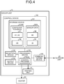
- FIG. 4 is a block diagram illustrating an example of a configuration of the indoor unit 10 according to the present embodiment.
- the indoor unit 10 has a heating unit 15 and a control device 100.
- the heating unit 15 is a unit that performs the heating operation of the indoor unit 10.
- the control device 100 (computer) performs not only an operation control of the heating unit 15 (that is, the indoor unit 10) but also an operation control of the heater 30.
- the control device 100 has a storage device 101, a reception device 102, a communication device 103, an output device 104, and a processing device 105.
- the storage device 101 includes an HDD, a RAM, a nonvolatile memory, a register, and the like. Various data including configuration data CONF and sensor data SEN are stored in the storage device 101.
- the configuration data CONF includes the threshold data DT indicating the first threshold X1 and the second threshold X2 and set temperature data DS indicating the set temperature XS.
- the threshold data DT and the set temperature data DS can be variably set by a user. Therefore, for example, the configuration data CONF is stored in a rewritable nonvolatile memory.
- the sensor data SEN includes the outdoor air temperature data DE indicating the outdoor air temperature XE and indoor temperature data DI indicating the indoor temperature XI.
- the outdoor air temperature data DE and the indoor temperature data DI are generated by sensors and transmitted to the control device 100.
- the sensor data SEN is stored in a RAM or a register.
- the reception device 102 receives a setting signal input by a user.
- the setting signal includes the above-mentioned threshold designation signal ST for setting the threshold data DT and a set-temperature designation signal for setting the set temperature data DS.
- the setting signal is transmitted from a wireless remote controller by a user.
- the communication device 103 performs data communication with the outdoor unit 20. For example, the communication device 103 receives the outdoor air temperature data DE indicating the outdoor air temperature XE detected by the outdoor unit 20.
- the output device 104 includes a display device and a speaker, and provides various notices to the user.
- the processing device 105 executes controls of respective devices and computation of various data. Particularly, the processing device 105 executes a control program PROG to perform an operation control of the heater 30 described below. Note that the control program PROG can be recorded on a computer-readable recording medium.
- FIG. 5 illustrates a functional configuration (functional blocks) related to the operation control of the heater 30.
- the indoor unit 10 (the control device 100) has a storage unit 110, a reception unit 120, a reception signal determination unit 130, a threshold setting unit 140, a communication unit 150, a heater control determination unit 160, and a heater operation control unit 170.
- the storage unit 110 stores therein the threshold data DT, the set temperature data DS, the outdoor air temperature data DE, and the indoor temperature data DI.
- the storage unit 110 is realized by the storage device 101.
- the reception unit 120 is realized by the reception device 102.
- the communication unit 150 is realized by the communication device 103.
- the reception signal determination unit 130, the threshold setting unit 140, the heater control determination unit 160, and the heater operation control unit 170 are realized by the processing device 105 executing the control program PROG.
- the reception unit 120 receives a setting signal input by a user.
- the setting signal includes the threshold designation signal ST for setting the threshold data DT and the set-temperature designation signal for setting the set temperature data DS.
- the reception signal determination unit 130 determines whether or not the setting signal received by the reception unit 120 is the threshold designation signal ST.
- the set temperature data DS (that is, the set temperature XS) is set in accordance with the set-temperature designation signal.
- the threshold designation signal ST designates at least one of the first threshold X1 and the second threshold X2.
- the threshold setting unit 140 checks a content designated by the threshold designation signal ST. More specifically, the threshold setting unit 140 checks whether or not a relation "X1 ⁇ X2" is satisfied when the threshold data DT is updated in accordance with the designation by the threshold designation signal ST.
- the threshold setting unit 140 sets (updates), based on the designation by the threshold designation signal ST, the threshold data DT stored in the storage unit 110.
- the threshold setting unit 140 may output an alarm by using the output device 104, instead of or along with the correction process.
- the alarm includes error display on a display device and ringing of a buzzer. As a result, it is possible to prompt a user to perform resetting.
- An outdoor air temperature acquisition unit 210 of the outdoor unit 20 detects the outdoor air temperature XE, and generates the outdoor air temperature data DE indicating the detected outdoor air temperature XE.
- a communication unit 220 of the outdoor unit 20 transmits the outdoor air temperature data DE to the indoor unit 10.
- the communication unit 150 of the indoor unit 10 receives the outdoor air temperature data DE from the outdoor unit 20.
- the outdoor air temperature data DE is stored in the storage unit 110.
- the heater control determination unit 160 reads the threshold data DT and the outdoor air temperature data DE from the storage unit 110. Then, the heater control determination unit 160 compares the first threshold X1 and the second threshold X2 with the outdoor air temperature XE.
- Step S12 When the outdoor air temperature XE is equal to or lower than the first threshold X1 (Step S12; Yes), the heater control determination unit 160 enables the control of the heater 30. After that, the process proceeds to Step S20.
- Step S12; No, Step S14; Yes the heater control determination unit 160 disables the control of the heater 30. After that, the process proceeds to Step S20.
- Step S12; No, Step S14; No When the outdoor air temperature XE is higher than the first threshold X1 and is lower than the second threshold X2 (Step S12; No, Step S14; No), the heater control determination unit 160 maintains the current control state. After that, the process proceeds to Step S20.
- the heater operation control unit 170 checks whether the control of the heater 30 is enabled or disabled.
- Step S20 When the control of the heater 30 is enabled (Step S20; Yes), the heater operation control unit 170 reads the indoor temperature data DI and the set temperature data DS from the storage unit 110. Then, the heater operation control unit 170 compares the indoor temperature XI and the set temperature XS.
- Step S21 When the indoor temperature XI is lower than the set temperature XS (Step S21; Yes), the heater operation control unit 170 turns ON the operation of the heater 30. After that, the process proceeds to Step S24.
- Step S21; No when the indoor temperature XI is higher than the set temperature XS (Step S21; No), the heater operation control unit 170 turns OFF the operation of the heater 30. Also, when the control of the heater 30 is disabled (Step S20; No), the heater operation control unit 170 turns OFF the operation of the heater 30. After that, the process proceeds to Step S24.
- the acquisition of the outdoor air temperature XE is performed regularly, for example.
- the process returns back to Step S10.
- the process returns back to Step S20.
- the above-described process is performed each time the outdoor air temperature XE is updated.
- the threshold data DT used as the criteria for determining whether to enable or disable the control of the heater 30 is variable. That is, it is possible to freely set the threshold data DT depending on a region or an environment in which the air conditioner 1 is placed. Therefore, such the situation as the heater 30 is wastefully in the ON-state even when demands can be fulfilled only by heating capacity of the indoor unit 10 can be prevented from occurring. That is to say, it is possible to achieve further energy saving according to the present embodiment.
- FIG. 9 is a block diagram illustrating an example of a functional configuration of the air conditioner 1 according to a second embodiment of the present invention. Overlapping description with the first embodiment will be omitted as appropriate.
- a relay 50 is connected between the heater 30 and a power supply 40.
- the heater operation control unit 170 ON/OFF controls the operation of the heater 30 by switching the relay 50.
- high-frequency switching of the relay 50 causes welding. Therefore, in the present embodiment, the heater operation control unit 170 prohibits a next switching for a certain period of time after switching the switching state of the relay 50. That is to say, the heater operation control unit 170 prohibits ON/OFF switching of the operation of the heater 30 for a certain period of time after performing ON/OFF switching of the operation of the heater 30.
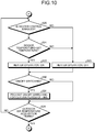
- FIG. 10 is a flowchart illustrating an operation of the heater operation control unit 170 in the present embodiment and corresponds to the foregoing FIG. 8 . As compared with FIG. 8 , Steps S30 and S31 are added between Step S22 or S23 and Step S24.
- Step S30 the heater operation control unit 170 checks whether or not ON/OFF switching of the heater 30 has occurred at the previous Step S22 or S23. If no ON/OFF switching has occurred (Step S30; No), the process proceeds to Step S24. On the other hand, if ON/OFF switching has occurred (Step S30; Yes), the heater operation control unit 170 prohibits ON/OFF switching of the heater 30 for a certain period of time (Step S31). For example, the heater operation control unit 170 interrupts the control flow for a certain period of time.
- an effect that the welding of the relay 50 is prevented can be obtained in addition to the same effects as in the case of the first embodiment.
- product quality is improved.
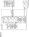
- FIG. 11 is a block diagram illustrating an example of a functional configuration of the air conditioner 1 according to a third embodiment of the present invention. Overlapping description with the first embodiment will be omitted as appropriate.
- a circulator 60 is provided along with the heater 30.
- the heater operation control unit 170 ON/OFF controls the circulator 60 in conjunction with ON/OFF of the operation of the heater 30. As the heater 30 and the circulator 60 operate in conjunction with each other, warm air is diffused and comfort is improved.
- an effect that the comfort is improved can be obtained in addition to the same effects as in the case of the first embodiment. It should be noted that a combination of the second embodiment and the third embodiment also is possible.
Landscapes
- Engineering & Computer Science (AREA)
- General Engineering & Computer Science (AREA)
- Chemical & Material Sciences (AREA)
- Combustion & Propulsion (AREA)
- Mechanical Engineering (AREA)
- Signal Processing (AREA)
- Physics & Mathematics (AREA)
- Human Computer Interaction (AREA)
- Mathematical Physics (AREA)
- Fuzzy Systems (AREA)
- General Physics & Mathematics (AREA)
- Automation & Control Theory (AREA)
- Air Conditioning Control Device (AREA)
Description
- The present invention relates to an air conditioner and a control program thereof.
-
Patent Literature 1 discloses an air conditioner that has an indoor unit and an electric heater, and performs an operation control of the electric heater as well. The air conditioner compares a load capacitance value and an outdoor air temperature with a predetermined heater stop condition. If the load capacitance value and the outdoor air temperature satisfy the predetermined heater stop condition, the air conditioner stops an operation of the electric heater regardless of an indoor temperature. - Patent Literature 1: Japanese Patent Application Laid-open No.
S62-162840 - In the case of
Patent Literature 1, the heater stop condition for stopping the operation of the electric heater is fixed. Therefore, there is a possibility that the electric heater is wastefully in the ON-state even when demands can be fulfilled only by heating capacity of the indoor unit, depending on a region or an environment. This is not preferable in view of energy saving. - An object of the present invention is to provide a technique that can achieve further energy saving with regard to an air conditioner performing an operation control of a heater.
- In an aspect of the present invention, an air conditioner is provided. The air conditioner has: an indoor unit; an outdoor unit to detect an outdoor air temperature; and a control device mounted on the indoor unit and performing operation controls of the indoor unit and a heater placed indoor. The control device has a storage unit, a heater control determination unit, a heater operation control unit, a reception unit, and a threshold setting unit. The storage unit stores therein threshold data indicating a first threshold and a second threshold. The heater control determination unit reads the threshold data from the storage unit, enables a control of the heater when the outdoor air temperature is equal to or lower than the first threshold, and disables the control of the heater when the outdoor air temperature is equal to or higher than the second threshold. The heater operation control unit sets an operation of the heater to be always-off when the control of the heater is disabled, and ON/OFF controls the operation of the heater based on a relation between an indoor temperature and a set temperature when the control of the heater is enabled. The reception unit receives a threshold designation signal input by a user and designating at least one of the first threshold and the second threshold. The threshold setting unit sets, based on designation by the received threshold designation signal, the threshold data stored in the storage unit.
- In another aspect of the present invention, a control program for an air conditioner is provided. The air conditioner has: an indoor unit; an outdoor unit detecting an outdoor air temperature; and a computer mounted on the indoor unit and performing operation controls of the indoor unit and a heater placed indoor.
- The control program causes the computer to execute the following steps of: reading threshold data indicating a first threshold and a second threshold from a storage unit storing therein the threshold data; enabling a control of the heater when the outdoor air temperature is equal to or lower than the first threshold; disabling the control of the heater when the outdoor air temperature is equal to or higher than the second threshold; setting an operation of the heater to be always-off when the control of the heater is disabled; ON/OFF controlling the operation of the heater based on a relation between an indoor temperature and a set temperature when the control of the heater is enabled; receiving a threshold designation signal input by a user and designating at least one of the first threshold and the second threshold; and setting, based on designation by the received threshold designation signal, the threshold data stored in the storage unit.
- According to the present invention, it is possible to achieve further energy saving with regard to the air conditioner performing the operation control of the heater.
-
-
FIG. 1 is a block diagram illustrating an outline of a first embodiment of the present invention. -
FIG. 2 is a conceptual diagram for explaining enabling/disabling of a heater control in an air conditioner according to the first embodiment of the present invention. -
FIG. 3 is a conceptual diagram for explaining ON/OFF control of a heater operation in the air conditioner according to the first embodiment of the present invention. -
FIG. 4 is a block diagram illustrating an example of a configuration of an indoor unit of the air conditioner according to the first embodiment of the present invention. -
FIG. 5 is a block diagram illustrating an example of a functional configuration of the air conditioner according to the first embodiment of the present invention. -
FIG. 6 is a flowchart illustrating a process flow in the air conditioner according to the first embodiment of the present invention. -
FIG. 7 is a flowchart illustrating a process flow in the air conditioner according to the first embodiment of the present invention. -
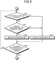
FIG. 8 is a flowchart illustrating a process flow in the air conditioner according to the first embodiment of the present invention. -
FIG. 9 is a block diagram illustrating an example of a functional configuration of an air conditioner according to a second embodiment of the present invention. -
FIG. 10 is a flowchart illustrating a process flow in the air conditioner according to the second embodiment of the present invention. -
FIG. 11 is a block diagram illustrating an example of a functional configuration of an air conditioner according to a third embodiment of the present invention. - An air conditioner according to embodiments of the present invention will be described with reference to the accompanying drawings.
-
FIG. 1 is a block diagram illustrating an outline of a first embodiment of the present invention. Anair conditioner 1 has anindoor unit 10 placed indoor and anoutdoor unit 20 placed outdoor. Furthermore, aheater 30 is placed indoor. Theheater 30 is used as an auxiliary heat source at a time of a heating operation. Typically, theheater 30 is an electric heater. It should be noted that theheater 30 may be, or may not be, a constituent element of theair conditioner 1. - The
air conditioner 1 according to the present embodiment has a function of performing operation controls of theheater 30 as well as theindoor unit 10 and theoutdoor unit 20. More specifically, the indoor unit 10 (a control device of theindoor unit 10, described later) has a function of performing an operation control of theheater 30. Basically, the operation control of theheater 30 is performed at the time of the heating operation. In the following description, it is assumed that theair conditioner 1 is performing the heating operation, unless otherwise specified. - The operation control of the
heater 30 includes (A) determining whether to enable or disable a control of theheater 30, and (B) ON/OFF controlling an operation of theheater 30. - The former (A), namely, determining whether to enable or disable the control of the
heater 30 is performed based on an outdoor air temperature XE. The outdoor air temperature XE is detected by theoutdoor unit 20, and outdoor air temperature data DE indicating the detected outdoor air temperature XE is transmitted from theoutdoor unit 20 to theindoor unit 10. Meanwhile, theindoor unit 10 holds threshold data DT indicating a first threshold X1 and a second threshold X2. The first threshold X1 and the second threshold X2 are criteria used for determining whether to enable or disable the control of theheater 30. - More specifically, as shown in
FIG. 2 , when the outdoor air temperature XE becomes equal to or lower than the first threshold X1, theindoor unit 10 enables the control of theheater 30. On the other hand, when the outdoor air temperature XE becomes equal to or higher than the second threshold X2, theindoor unit 10 disables the control of theheater 30. In a case where the first threshold X1 and the second threshold X2 are equal to each other (X1=X2), switching between enabling and disabling may be caused repeatedly in a short time due to disturbance of the outdoor air temperature XE. From a viewpoint of a stable control, a hysteresis characteristic such as the first threshold X1 being lower than the second threshold X2 (X1<X2) as shown inFIG. 2 is preferable. However, the present embodiment does not eliminate a case where the first threshold X1 and the second threshold X2 are equal to each other. - Next, the latter (B), namely, ON/OFF controlling the operation of the
heater 30 will be described with reference toFIG. 3 . When the control of theheater 30 is disabled, theindoor unit 10 sets the operation of theheater 30 to be always-off. On the other hand, when the control of theheater 30 is enabled, theindoor unit 10 ON/OFF controls the operation of theheater 30. - More specifically, the
indoor unit 10 ON/OFF controls the operation of theheater 30 based on a relation between an indoor temperature XI and a set temperature. For example, when the indoor temperature XI is lower than the set temperature, theindoor unit 10 turns ON the operation of theheater 30. On the other hand, when the indoor temperature XI is higher than the set temperature, theindoor unit 10 turns OFF the operation of theheater 30. - Referring to
FIG. 1 again, according to the present embodiment, the threshold data DT, that is, the first threshold X1 and the second threshold X2 can be variably set. More specifically, a threshold designation signal ST designating at least one of the first threshold X1 and the second threshold X2 is input to theindoor unit 10 by a user. Typically, the user operates a wireless remote controller to transmit the threshold designation signal ST to theindoor unit 10. Note that the method of inputting the threshold designation signal ST is not limited to the transmission with the wireless remote controller. Then, theindoor unit 10 sets (updates) the content of the threshold data DT based on the designation by the received threshold designation signal ST. - In this manner, according to the present embodiment, the threshold data DT used as the criteria for determining whether to enable or disable the control of the
heater 30 is variable. That is, it is possible to freely set the threshold data DT depending on a region or an environment in which theair conditioner 1 is placed. Therefore, such the situation as theheater 30 is wastefully in the ON-state even when demands can be fulfilled only by heating capacity of theindoor unit 10 can be prevented from occurring. That is to say, it is possible to achieve further energy saving according to the present embodiment. -
FIG. 4 is a block diagram illustrating an example of a configuration of theindoor unit 10 according to the present embodiment. Theindoor unit 10 has aheating unit 15 and acontrol device 100. Theheating unit 15 is a unit that performs the heating operation of theindoor unit 10. The control device 100 (computer) performs not only an operation control of the heating unit 15 (that is, the indoor unit 10) but also an operation control of theheater 30. Thecontrol device 100 has astorage device 101, areception device 102, acommunication device 103, an output device 104, and aprocessing device 105. - The
storage device 101 includes an HDD, a RAM, a nonvolatile memory, a register, and the like. Various data including configuration data CONF and sensor data SEN are stored in thestorage device 101. - The configuration data CONF includes the threshold data DT indicating the first threshold X1 and the second threshold X2 and set temperature data DS indicating the set temperature XS. The threshold data DT and the set temperature data DS can be variably set by a user. Therefore, for example, the configuration data CONF is stored in a rewritable nonvolatile memory.
- The sensor data SEN includes the outdoor air temperature data DE indicating the outdoor air temperature XE and indoor temperature data DI indicating the indoor temperature XI. The outdoor air temperature data DE and the indoor temperature data DI are generated by sensors and transmitted to the
control device 100. For example, the sensor data SEN is stored in a RAM or a register. - The
reception device 102 receives a setting signal input by a user. The setting signal includes the above-mentioned threshold designation signal ST for setting the threshold data DT and a set-temperature designation signal for setting the set temperature data DS. Typically, the setting signal is transmitted from a wireless remote controller by a user. - The
communication device 103 performs data communication with theoutdoor unit 20. For example, thecommunication device 103 receives the outdoor air temperature data DE indicating the outdoor air temperature XE detected by theoutdoor unit 20. - The output device 104 includes a display device and a speaker, and provides various notices to the user.
- The
processing device 105 executes controls of respective devices and computation of various data. Particularly, theprocessing device 105 executes a control program PROG to perform an operation control of theheater 30 described below. Note that the control program PROG can be recorded on a computer-readable recording medium. -
FIG. 5 illustrates a functional configuration (functional blocks) related to the operation control of theheater 30. The indoor unit 10 (the control device 100) has astorage unit 110, areception unit 120, a receptionsignal determination unit 130, athreshold setting unit 140, acommunication unit 150, a heatercontrol determination unit 160, and a heateroperation control unit 170. - The
storage unit 110 stores therein the threshold data DT, the set temperature data DS, the outdoor air temperature data DE, and the indoor temperature data DI. Thestorage unit 110 is realized by thestorage device 101. Thereception unit 120 is realized by thereception device 102. Thecommunication unit 150 is realized by thecommunication device 103. The receptionsignal determination unit 130, thethreshold setting unit 140, the heatercontrol determination unit 160, and the heateroperation control unit 170 are realized by theprocessing device 105 executing the control program PROG. - First, an example of a flow of setting the threshold data DT will be described with reference to
FIG. 6 . - The
reception unit 120 receives a setting signal input by a user. The setting signal includes the threshold designation signal ST for setting the threshold data DT and the set-temperature designation signal for setting the set temperature data DS. - The reception
signal determination unit 130 determines whether or not the setting signal received by thereception unit 120 is the threshold designation signal ST. - If the received setting signal is the set-temperature designation signal (Step S2; No), the set temperature data DS (that is, the set temperature XS) is set in accordance with the set-temperature designation signal.
- If the received setting signal is the threshold designation signal ST (Step S2; Yes), the threshold designation signal ST designates at least one of the first threshold X1 and the second threshold X2. Here, the
threshold setting unit 140 checks a content designated by the threshold designation signal ST. More specifically, thethreshold setting unit 140 checks whether or not a relation "X1<X2" is satisfied when the threshold data DT is updated in accordance with the designation by the threshold designation signal ST. - If the relation "X1<X2" is satisfied (Step S4; Yes), the
threshold setting unit 140 sets (updates), based on the designation by the threshold designation signal ST, the threshold data DT stored in thestorage unit 110. - On the other hand, if the relation "X1<X2" is not satisfied, that is, if the first threshold X1 becomes equal to or higher than the second threshold X2 (Step S4; No), the
threshold setting unit 140 performs a correction process. More specifically, thethreshold setting unit 140 corrects the designation such that the relation "X1<X2" is satisfied. For example, thethreshold setting unit 140 corrects the first threshold X1 according to a relational expression "X1=X2-α (α: a positive number)". After that, the process proceeds to Step S5. In this case, thethreshold setting unit 140 sets (updates) the threshold data DT stored in thestorage unit 110 in accordance with the corrected designation. Due to the correction process described above, it is possible to automatically avoid erroneous setting. - It should be noted that in Step S6, the
threshold setting unit 140 may output an alarm by using the output device 104, instead of or along with the correction process. The alarm includes error display on a display device and ringing of a buzzer. As a result, it is possible to prompt a user to perform resetting. - Next, an example of the operation control of the
heater 30 will be described with reference toFIGS. 7 and8 . - An outdoor air
temperature acquisition unit 210 of theoutdoor unit 20 detects the outdoor air temperature XE, and generates the outdoor air temperature data DE indicating the detected outdoor air temperature XE. Acommunication unit 220 of theoutdoor unit 20 transmits the outdoor air temperature data DE to theindoor unit 10. Thecommunication unit 150 of theindoor unit 10 receives the outdoor air temperature data DE from theoutdoor unit 20. The outdoor air temperature data DE is stored in thestorage unit 110. - The heater
control determination unit 160 reads the threshold data DT and the outdoor air temperature data DE from thestorage unit 110. Then, the heatercontrol determination unit 160 compares the first threshold X1 and the second threshold X2 with the outdoor air temperature XE. - When the outdoor air temperature XE is equal to or lower than the first threshold X1 (Step S12; Yes), the heater
control determination unit 160 enables the control of theheater 30. After that, the process proceeds to Step S20. - When the outdoor air temperature XE is equal to or higher than the second threshold X2 (Step S12; No, Step S14; Yes), the heater
control determination unit 160 disables the control of theheater 30. After that, the process proceeds to Step S20. - When the outdoor air temperature XE is higher than the first threshold X1 and is lower than the second threshold X2 (Step S12; No, Step S14; No), the heater
control determination unit 160 maintains the current control state. After that, the process proceeds to Step S20. - The heater
operation control unit 170 checks whether the control of theheater 30 is enabled or disabled. - When the control of the
heater 30 is enabled (Step S20; Yes), the heateroperation control unit 170 reads the indoor temperature data DI and the set temperature data DS from thestorage unit 110. Then, the heateroperation control unit 170 compares the indoor temperature XI and the set temperature XS. - When the indoor temperature XI is lower than the set temperature XS (Step S21; Yes), the heater
operation control unit 170 turns ON the operation of theheater 30. After that, the process proceeds to Step S24. - On the other hand, when the indoor temperature XI is higher than the set temperature XS (Step S21; No), the heater
operation control unit 170 turns OFF the operation of theheater 30. Also, when the control of theheater 30 is disabled (Step S20; No), the heateroperation control unit 170 turns OFF the operation of theheater 30. After that, the process proceeds to Step S24. - The acquisition of the outdoor air temperature XE is performed regularly, for example. When it comes to an acquisition timing of the outdoor air temperature XE (Step S24; Yes), the process returns back to Step S10. In other cases (Step S24; No), the process returns back to Step S20. The above-described process is performed each time the outdoor air temperature XE is updated.
- As described above, according to the present embodiment, the threshold data DT used as the criteria for determining whether to enable or disable the control of the
heater 30 is variable. That is, it is possible to freely set the threshold data DT depending on a region or an environment in which theair conditioner 1 is placed. Therefore, such the situation as theheater 30 is wastefully in the ON-state even when demands can be fulfilled only by heating capacity of theindoor unit 10 can be prevented from occurring. That is to say, it is possible to achieve further energy saving according to the present embodiment. -
FIG. 9 is a block diagram illustrating an example of a functional configuration of theair conditioner 1 according to a second embodiment of the present invention. Overlapping description with the first embodiment will be omitted as appropriate. - In the present embodiment, a
relay 50 is connected between theheater 30 and apower supply 40. The heateroperation control unit 170 ON/OFF controls the operation of theheater 30 by switching therelay 50. Here, high-frequency switching of therelay 50 causes welding. Therefore, in the present embodiment, the heateroperation control unit 170 prohibits a next switching for a certain period of time after switching the switching state of therelay 50. That is to say, the heateroperation control unit 170 prohibits ON/OFF switching of the operation of theheater 30 for a certain period of time after performing ON/OFF switching of the operation of theheater 30. -
FIG. 10 is a flowchart illustrating an operation of the heateroperation control unit 170 in the present embodiment and corresponds to the foregoingFIG. 8 . As compared withFIG. 8 , Steps S30 and S31 are added between Step S22 or S23 and Step S24. - At Step S30, the heater
operation control unit 170 checks whether or not ON/OFF switching of theheater 30 has occurred at the previous Step S22 or S23. If no ON/OFF switching has occurred (Step S30; No), the process proceeds to Step S24. On the other hand, if ON/OFF switching has occurred (Step S30; Yes), the heateroperation control unit 170 prohibits ON/OFF switching of theheater 30 for a certain period of time (Step S31). For example, the heateroperation control unit 170 interrupts the control flow for a certain period of time. - According to the present embodiment, an effect that the welding of the
relay 50 is prevented can be obtained in addition to the same effects as in the case of the first embodiment. As a result, product quality is improved. -
FIG. 11 is a block diagram illustrating an example of a functional configuration of theair conditioner 1 according to a third embodiment of the present invention. Overlapping description with the first embodiment will be omitted as appropriate. - In the present embodiment, a
circulator 60 is provided along with theheater 30. The heateroperation control unit 170 ON/OFF controls thecirculator 60 in conjunction with ON/OFF of the operation of theheater 30. As theheater 30 and thecirculator 60 operate in conjunction with each other, warm air is diffused and comfort is improved. - According to the present embodiment, an effect that the comfort is improved can be obtained in addition to the same effects as in the case of the first embodiment. It should be noted that a combination of the second embodiment and the third embodiment also is possible.
- Embodiments of the present invention have been described above with reference to the accompanying drawings. It should be noted that the present invention is not limited to the embodiments described above, and can be modified as appropriate by persons skilled in the art without departing from the scope thereof.
- 1 air conditioner, 10 indoor unit, 15 heating unit, 20 outdoor unit, 30 heater, 40 power supply, 50 relay, 60 circulator, 100 control device, 101 storage device, 102 reception device, 103 communication device, 104 output device, 105 processing device, 110 storage unit, 120 reception unit, 130 reception signal determination unit, 140 threshold setting unit, 150 communication unit, 160 heater control determination unit, 170 heater operation control unit, 210 outdoor air temperature acquisition unit, 220 communication unit, CONF configuration data, DE outdoor air temperature data, DI indoor temperature data, DS set temperature data, DT threshold data, PROG control program, SEN sensor data, ST threshold designation signal, X1 first threshold, X2 second threshold, XE outdoor air temperature, XI indoor temperature, XS set temperature.
Claims (8)
- An air conditioner comprising:an indoor unit;an outdoor unit to detect an outdoor air temperature; anda control device mounted on the indoor unit and performing operation controls of the indoor unit and a heater placed indoor,wherein the control device comprises:a storage unit to store therein threshold data indicating a first threshold and a second threshold;a heater control determination unit to read the threshold data from the storage unit, to enable a control of the heater when the outdoor air temperature is equal to or lower than the first threshold, and to disable the control of the heater when the outdoor air temperature is equal to or higher than the second threshold;a heater operation control unit to set an operation of the heater to be always-off when the control of the heater is disabled, and to ON/OFF control the operation of the heater based on a relation between an indoor temperature and a set temperature when the control of the heater is enabled;a reception unit to receive a threshold designation signal input by a user and designating at least one of the first threshold and the second threshold; anda threshold setting unit to set, based on designation by the received threshold designation signal, the threshold data stored in the storage unit.
- The air conditioner according to claim 1,
wherein the first threshold is lower than the second threshold. - The air conditioner according to claim 2,
wherein if the first threshold becomes equal to or higher than the second threshold as a result of the designation by the received threshold designation signal, the threshold setting unit corrects the designation such that the first threshold becomes lower than the second threshold and then sets the threshold data stored in the storage unit in accordance with the corrected designation. - The air conditioner according to claim 2,
wherein if the first threshold becomes equal to or higher than the second threshold as a result of the designation by the received threshold designation signal, the threshold setting unit outputs an alarm. - The air conditioner according to any one of claims 1 to 4,
wherein when the control of the heater is enabled, the heater operation control unit turns ON the operation of the heater when the indoor temperature is lower than the set temperature and turns OFF the operation of the heater when the indoor temperature is higher than the set temperature. - The air conditioner according to any one of claims 1 to 5,
wherein the heater operation control unit ON/OFF controls the operation of the heater by switching a relay connected between the heater and a power supply, and
the heater operation control unit prohibits ON/OFF switching of the operation of the heater for a certain period of time after performing ON/OFF switching of the operation of the heater. - The air conditioner according to any one of claims 1 to 6,
wherein the heater operation control unit ON/OFF controls a circulator in conjunction with ON/OFF of the operation of the heater. - A control program for an air conditioner,
wherein the air conditioner comprises:an indoor unit;an outdoor unit to detect an outdoor air temperature; anda computer mounted on the indoor unit and performing operation controls of the indoor unit and a heater placed indoor,wherein the control program causes the computer to execute steps of:reading threshold data indicating a first threshold and a second threshold from a storage unit storing therein the threshold data;enabling a control of the heater when the outdoor air temperature is equal to or lower than the first threshold;disabling the control of the heater when the outdoor air temperature is equal to or higher than the second threshold;setting an operation of the heater to be always-off when the control of the heater is disabled;ON/OFF controlling the operation of the heater based on a relation between an indoor temperature and a set temperature when the control of the heater is enabled;receiving a threshold designation signal input by a user and designating at least one of the first threshold and the second threshold; andsetting, based on designation by the received threshold designation signal, the threshold data stored in the storage unit.
Applications Claiming Priority (2)
| Application Number | Priority Date | Filing Date | Title |
|---|---|---|---|
| JP2014025939A JP6120786B2 (en) | 2014-02-13 | 2014-02-13 | Air conditioner and control program |
| PCT/JP2014/082882 WO2015122089A1 (en) | 2014-02-13 | 2014-12-11 | Air conditioner and control program |
Publications (3)
| Publication Number | Publication Date |
|---|---|
| EP3106769A1 true EP3106769A1 (en) | 2016-12-21 |
| EP3106769A4 EP3106769A4 (en) | 2017-10-18 |
| EP3106769B1 EP3106769B1 (en) | 2020-04-01 |
Family
ID=53799844
Family Applications (1)
| Application Number | Title | Priority Date | Filing Date |
|---|---|---|---|
| EP14882475.8A Active EP3106769B1 (en) | 2014-02-13 | 2014-12-11 | Air conditioner and control program |
Country Status (9)
| Country | Link |
|---|---|
| US (1) | US10126008B2 (en) |
| EP (1) | EP3106769B1 (en) |
| JP (1) | JP6120786B2 (en) |
| CN (1) | CN105849471B (en) |
| AU (1) | AU2014382358B2 (en) |
| CA (1) | CA2938006C (en) |
| ES (1) | ES2786325T3 (en) |
| RU (1) | RU2636915C1 (en) |
| WO (1) | WO2015122089A1 (en) |
Families Citing this family (5)
| Publication number | Priority date | Publication date | Assignee | Title |
|---|---|---|---|---|
| CN105509236B (en) * | 2015-12-18 | 2018-03-30 | 奥克斯空调股份有限公司 | The control method of air-conditioning auxiliary electrical heater |
| KR101951675B1 (en) * | 2017-03-28 | 2019-02-25 | 엘지전자 주식회사 | Air conditioner having power saving function |
| CN109855249A (en) * | 2018-12-27 | 2019-06-07 | 红塔烟草(集团)有限责任公司 | A kind of energy-efficient air conditioner temperature controlling method |
| RU2742475C1 (en) * | 2020-07-24 | 2021-02-08 | Юрий Александрович Домкин | Control device for winter set of air conditioner |
| CN113154542A (en) * | 2021-02-02 | 2021-07-23 | 青岛海尔空调器有限总公司 | Indoor cabinet air conditioner and control method of indoor cabinet air conditioner |
Family Cites Families (21)
| Publication number | Priority date | Publication date | Assignee | Title |
|---|---|---|---|---|
| JPS62162840A (en) | 1986-01-10 | 1987-07-18 | Daikin Ind Ltd | Air conditioner |
| JPH0442665Y2 (en) | 1987-05-13 | 1992-10-08 | ||
| JP3375016B2 (en) * | 1994-12-01 | 2003-02-10 | 東京瓦斯株式会社 | Floor heating device and air conditioner operation control device in hot water central heating system using one-button remote control |
| JPH11182994A (en) | 1997-12-18 | 1999-07-06 | Toshiba Corp | Air conditioner |
| JP2002181367A (en) * | 2000-12-13 | 2002-06-26 | Fujitsu General Ltd | Control method of air conditioner |
| KR100423972B1 (en) * | 2001-11-30 | 2004-03-22 | 삼성전자주식회사 | Air conditioner and therof control method |
| US7085626B2 (en) | 2004-04-15 | 2006-08-01 | York International Corporation | Method and apparatus to prevent low temperature damage using an HVAC control |
| US7827813B2 (en) * | 2007-01-30 | 2010-11-09 | Johnson Controls Technology Company | Adaptive real-time optimization control |
| AU2010225946B2 (en) * | 2009-03-19 | 2013-03-07 | Daikin Industries, Ltd. | Air conditioning apparatus |
| JP5423083B2 (en) * | 2009-03-19 | 2014-02-19 | ダイキン工業株式会社 | Air conditioner |
| JP5434247B2 (en) * | 2009-05-12 | 2014-03-05 | ダイキン工業株式会社 | Air conditioner |
| KR101605901B1 (en) * | 2009-09-11 | 2016-03-23 | 엘지전자 주식회사 | Air conditioner and control method thereof |
| JP5221596B2 (en) * | 2010-06-10 | 2013-06-26 | シャープ株式会社 | Air conditioner |
| WO2012047938A2 (en) * | 2010-10-04 | 2012-04-12 | Global Solar Water And Power Systems, Inc. | Multiplatform heating ventilation and air conditioning control system |
| CN102878646B (en) * | 2011-07-14 | 2014-12-03 | 北汽福田汽车股份有限公司 | Air-conditioner control system and method for electric vehicle |
| JP5665781B2 (en) | 2012-02-23 | 2015-02-04 | 三菱電機株式会社 | Air conditioning system |
| US20130291569A1 (en) * | 2012-05-04 | 2013-11-07 | Narayanan M. Subramanian | Air conditioning system performance monitor |
| US9886419B2 (en) | 2012-07-26 | 2018-02-06 | Tektronix, Inc. | System for improving probability of transient event detection |
| US8600561B1 (en) * | 2012-09-30 | 2013-12-03 | Nest Labs, Inc. | Radiant heating controls and methods for an environmental control system |
| JP5935006B2 (en) * | 2012-10-24 | 2016-06-15 | パナソニックIpマネジメント株式会社 | Control device and program |
| JP2013053845A (en) * | 2012-11-12 | 2013-03-21 | Mitsubishi Electric Corp | Air-conditioning system |
-
2014
- 2014-02-13 JP JP2014025939A patent/JP6120786B2/en not_active Expired - Fee Related
- 2014-12-11 US US15/033,209 patent/US10126008B2/en active Active
- 2014-12-11 RU RU2016130624A patent/RU2636915C1/en active
- 2014-12-11 EP EP14882475.8A patent/EP3106769B1/en active Active
- 2014-12-11 CN CN201480071167.5A patent/CN105849471B/en not_active Expired - Fee Related
- 2014-12-11 ES ES14882475T patent/ES2786325T3/en active Active
- 2014-12-11 AU AU2014382358A patent/AU2014382358B2/en not_active Ceased
- 2014-12-11 WO PCT/JP2014/082882 patent/WO2015122089A1/en not_active Ceased
- 2014-12-11 CA CA2938006A patent/CA2938006C/en active Active
Also Published As
| Publication number | Publication date |
|---|---|
| ES2786325T3 (en) | 2020-10-09 |
| CA2938006C (en) | 2018-07-10 |
| JP2015152217A (en) | 2015-08-24 |
| AU2014382358A1 (en) | 2016-05-19 |
| US10126008B2 (en) | 2018-11-13 |
| WO2015122089A1 (en) | 2015-08-20 |
| RU2636915C1 (en) | 2017-11-28 |
| JP6120786B2 (en) | 2017-04-26 |
| US20160265801A1 (en) | 2016-09-15 |
| EP3106769A4 (en) | 2017-10-18 |
| CN105849471B (en) | 2018-12-14 |
| CA2938006A1 (en) | 2015-08-20 |
| CN105849471A (en) | 2016-08-10 |
| EP3106769B1 (en) | 2020-04-01 |
| AU2014382358B2 (en) | 2017-02-16 |
Similar Documents
| Publication | Publication Date | Title |
|---|---|---|
| EP3106769B1 (en) | Air conditioner and control program | |
| US9129511B2 (en) | Presence deciding apparatus, system, method and program | |
| EP4242543A1 (en) | Control method and apparatus for air conditioner compressor, and air conditioner | |
| US20130261769A1 (en) | Context recognition apparatus and method | |
| MX2009012227A (en) | Load management thermostat. | |
| CN109442674B (en) | Air conditioner compressor protection method, equipment, device, storage medium and air conditioner | |
| EP4180737A1 (en) | Control method and apparatus for air conditioning compressor, and air conditioner | |
| EP3073115B1 (en) | Compressor overload-protection control method and apparatus | |
| US20150248135A1 (en) | Method and electronic device for controlling current | |
| JP6476624B2 (en) | Air conditioner | |
| US10228154B2 (en) | Control apparatus, control system and control method | |
| EP3643976A1 (en) | Method and device for controlling air conditioner | |
| CN106407143B (en) | Method and device for controlling hot plug operation of CPU in mobile terminal | |
| JP2012252373A (en) | Self-diagnosis device, self-diagnosis method, and program | |
| CN115143638B (en) | Water heater control method and electronic equipment | |
| JP2010163272A (en) | Air conditioner for elevator | |
| JP6724345B2 (en) | Demand control device | |
| JP2015210135A (en) | Electric power measurement device | |
| US20160103722A1 (en) | Hardware lockup detection mechanism for user devices | |
| KR20160069252A (en) | Device Having Function of Controlling Discharge Current of Battery | |
| KR20110118106A (en) | Multi-tap with standby power off function | |
| JP2018085920A (en) | Energy management system, energy management apparatus, terminal, and energy management method | |
| US20220290867A1 (en) | Cooktop, cooktop system, control method and apparatus, and storage medium | |
| JP5721272B2 (en) | Device status monitoring determination apparatus, method, and program | |
| AU2018452878A1 (en) | Air-conditioning control system |
Legal Events
| Date | Code | Title | Description |
|---|---|---|---|
| PUAI | Public reference made under article 153(3) epc to a published international application that has entered the european phase |
Free format text: ORIGINAL CODE: 0009012 |
|
| STAA | Information on the status of an ep patent application or granted ep patent |
Free format text: STATUS: REQUEST FOR EXAMINATION WAS MADE |
|
| 17P | Request for examination filed |
Effective date: 20160610 |
|
| AK | Designated contracting states |
Kind code of ref document: A1 Designated state(s): AL AT BE BG CH CY CZ DE DK EE ES FI FR GB GR HR HU IE IS IT LI LT LU LV MC MK MT NL NO PL PT RO RS SE SI SK SM TR |
|
| AX | Request for extension of the european patent |
Extension state: BA ME |
|
| DAX | Request for extension of the european patent (deleted) | ||
| A4 | Supplementary search report drawn up and despatched |
Effective date: 20170919 |
|
| RIC1 | Information provided on ipc code assigned before grant |
Ipc: G05B 15/02 20060101ALI20170913BHEP Ipc: F24F 11/00 20060101AFI20170913BHEP |
|
| STAA | Information on the status of an ep patent application or granted ep patent |
Free format text: STATUS: EXAMINATION IS IN PROGRESS |
|
| 17Q | First examination report despatched |
Effective date: 20190227 |
|
| REG | Reference to a national code |
Ref country code: DE Ref legal event code: R079 Ref document number: 602014063337 Country of ref document: DE Free format text: PREVIOUS MAIN CLASS: F24F0011020000 Ipc: F24F0011300000 |
|
| GRAP | Despatch of communication of intention to grant a patent |
Free format text: ORIGINAL CODE: EPIDOSNIGR1 |
|
| STAA | Information on the status of an ep patent application or granted ep patent |
Free format text: STATUS: GRANT OF PATENT IS INTENDED |
|
| RIC1 | Information provided on ipc code assigned before grant |
Ipc: F24F 11/30 20180101AFI20191014BHEP Ipc: F24F 110/10 20180101ALN20191014BHEP Ipc: F24F 110/12 20180101ALN20191014BHEP Ipc: F24F 11/62 20180101ALN20191014BHEP |
|
| INTG | Intention to grant announced |
Effective date: 20191104 |
|
| GRAS | Grant fee paid |
Free format text: ORIGINAL CODE: EPIDOSNIGR3 |
|
| GRAA | (expected) grant |
Free format text: ORIGINAL CODE: 0009210 |
|
| STAA | Information on the status of an ep patent application or granted ep patent |
Free format text: STATUS: THE PATENT HAS BEEN GRANTED |
|
| AK | Designated contracting states |
Kind code of ref document: B1 Designated state(s): AL AT BE BG CH CY CZ DE DK EE ES FI FR GB GR HR HU IE IS IT LI LT LU LV MC MK MT NL NO PL PT RO RS SE SI SK SM TR |
|
| REG | Reference to a national code |
Ref country code: GB Ref legal event code: FG4D |
|
| REG | Reference to a national code |
Ref country code: AT Ref legal event code: REF Ref document number: 1251845 Country of ref document: AT Kind code of ref document: T Effective date: 20200415 Ref country code: CH Ref legal event code: EP |
|
| REG | Reference to a national code |
Ref country code: DE Ref legal event code: R096 Ref document number: 602014063337 Country of ref document: DE |
|
| REG | Reference to a national code |
Ref country code: IE Ref legal event code: FG4D |
|
| REG | Reference to a national code |
Ref country code: SE Ref legal event code: TRGR |
|
| PG25 | Lapsed in a contracting state [announced via postgrant information from national office to epo] |
Ref country code: BG Free format text: LAPSE BECAUSE OF FAILURE TO SUBMIT A TRANSLATION OF THE DESCRIPTION OR TO PAY THE FEE WITHIN THE PRESCRIBED TIME-LIMIT Effective date: 20200701 |
|
| REG | Reference to a national code |
Ref country code: NL Ref legal event code: MP Effective date: 20200401 |
|
| REG | Reference to a national code |
Ref country code: LT Ref legal event code: MG4D |
|
| REG | Reference to a national code |
Ref country code: ES Ref legal event code: FG2A Ref document number: 2786325 Country of ref document: ES Kind code of ref document: T3 Effective date: 20201009 |
|
| PG25 | Lapsed in a contracting state [announced via postgrant information from national office to epo] |
Ref country code: GR Free format text: LAPSE BECAUSE OF FAILURE TO SUBMIT A TRANSLATION OF THE DESCRIPTION OR TO PAY THE FEE WITHIN THE PRESCRIBED TIME-LIMIT Effective date: 20200702 Ref country code: IS Free format text: LAPSE BECAUSE OF FAILURE TO SUBMIT A TRANSLATION OF THE DESCRIPTION OR TO PAY THE FEE WITHIN THE PRESCRIBED TIME-LIMIT Effective date: 20200801 Ref country code: NL Free format text: LAPSE BECAUSE OF FAILURE TO SUBMIT A TRANSLATION OF THE DESCRIPTION OR TO PAY THE FEE WITHIN THE PRESCRIBED TIME-LIMIT Effective date: 20200401 Ref country code: LT Free format text: LAPSE BECAUSE OF FAILURE TO SUBMIT A TRANSLATION OF THE DESCRIPTION OR TO PAY THE FEE WITHIN THE PRESCRIBED TIME-LIMIT Effective date: 20200401 Ref country code: FI Free format text: LAPSE BECAUSE OF FAILURE TO SUBMIT A TRANSLATION OF THE DESCRIPTION OR TO PAY THE FEE WITHIN THE PRESCRIBED TIME-LIMIT Effective date: 20200401 Ref country code: PT Free format text: LAPSE BECAUSE OF FAILURE TO SUBMIT A TRANSLATION OF THE DESCRIPTION OR TO PAY THE FEE WITHIN THE PRESCRIBED TIME-LIMIT Effective date: 20200817 Ref country code: CZ Free format text: LAPSE BECAUSE OF FAILURE TO SUBMIT A TRANSLATION OF THE DESCRIPTION OR TO PAY THE FEE WITHIN THE PRESCRIBED TIME-LIMIT Effective date: 20200401 Ref country code: NO Free format text: LAPSE BECAUSE OF FAILURE TO SUBMIT A TRANSLATION OF THE DESCRIPTION OR TO PAY THE FEE WITHIN THE PRESCRIBED TIME-LIMIT Effective date: 20200701 |
|
| REG | Reference to a national code |
Ref country code: AT Ref legal event code: MK05 Ref document number: 1251845 Country of ref document: AT Kind code of ref document: T Effective date: 20200401 |
|
| PG25 | Lapsed in a contracting state [announced via postgrant information from national office to epo] |
Ref country code: HR Free format text: LAPSE BECAUSE OF FAILURE TO SUBMIT A TRANSLATION OF THE DESCRIPTION OR TO PAY THE FEE WITHIN THE PRESCRIBED TIME-LIMIT Effective date: 20200401 Ref country code: LV Free format text: LAPSE BECAUSE OF FAILURE TO SUBMIT A TRANSLATION OF THE DESCRIPTION OR TO PAY THE FEE WITHIN THE PRESCRIBED TIME-LIMIT Effective date: 20200401 Ref country code: RS Free format text: LAPSE BECAUSE OF FAILURE TO SUBMIT A TRANSLATION OF THE DESCRIPTION OR TO PAY THE FEE WITHIN THE PRESCRIBED TIME-LIMIT Effective date: 20200401 |
|
| PG25 | Lapsed in a contracting state [announced via postgrant information from national office to epo] |
Ref country code: AL Free format text: LAPSE BECAUSE OF FAILURE TO SUBMIT A TRANSLATION OF THE DESCRIPTION OR TO PAY THE FEE WITHIN THE PRESCRIBED TIME-LIMIT Effective date: 20200401 |
|
| REG | Reference to a national code |
Ref country code: DE Ref legal event code: R097 Ref document number: 602014063337 Country of ref document: DE |
|
| PG25 | Lapsed in a contracting state [announced via postgrant information from national office to epo] |
Ref country code: RO Free format text: LAPSE BECAUSE OF FAILURE TO SUBMIT A TRANSLATION OF THE DESCRIPTION OR TO PAY THE FEE WITHIN THE PRESCRIBED TIME-LIMIT Effective date: 20200401 Ref country code: AT Free format text: LAPSE BECAUSE OF FAILURE TO SUBMIT A TRANSLATION OF THE DESCRIPTION OR TO PAY THE FEE WITHIN THE PRESCRIBED TIME-LIMIT Effective date: 20200401 Ref country code: SM Free format text: LAPSE BECAUSE OF FAILURE TO SUBMIT A TRANSLATION OF THE DESCRIPTION OR TO PAY THE FEE WITHIN THE PRESCRIBED TIME-LIMIT Effective date: 20200401 Ref country code: EE Free format text: LAPSE BECAUSE OF FAILURE TO SUBMIT A TRANSLATION OF THE DESCRIPTION OR TO PAY THE FEE WITHIN THE PRESCRIBED TIME-LIMIT Effective date: 20200401 Ref country code: DK Free format text: LAPSE BECAUSE OF FAILURE TO SUBMIT A TRANSLATION OF THE DESCRIPTION OR TO PAY THE FEE WITHIN THE PRESCRIBED TIME-LIMIT Effective date: 20200401 |
|
| PLBE | No opposition filed within time limit |
Free format text: ORIGINAL CODE: 0009261 |
|
| STAA | Information on the status of an ep patent application or granted ep patent |
Free format text: STATUS: NO OPPOSITION FILED WITHIN TIME LIMIT |
|
| PG25 | Lapsed in a contracting state [announced via postgrant information from national office to epo] |
Ref country code: PL Free format text: LAPSE BECAUSE OF FAILURE TO SUBMIT A TRANSLATION OF THE DESCRIPTION OR TO PAY THE FEE WITHIN THE PRESCRIBED TIME-LIMIT Effective date: 20200401 Ref country code: SK Free format text: LAPSE BECAUSE OF FAILURE TO SUBMIT A TRANSLATION OF THE DESCRIPTION OR TO PAY THE FEE WITHIN THE PRESCRIBED TIME-LIMIT Effective date: 20200401 |
|
| 26N | No opposition filed |
Effective date: 20210112 |
|
| PG25 | Lapsed in a contracting state [announced via postgrant information from national office to epo] |
Ref country code: SI Free format text: LAPSE BECAUSE OF FAILURE TO SUBMIT A TRANSLATION OF THE DESCRIPTION OR TO PAY THE FEE WITHIN THE PRESCRIBED TIME-LIMIT Effective date: 20200401 |
|
| REG | Reference to a national code |
Ref country code: CH Ref legal event code: PL |
|
| PG25 | Lapsed in a contracting state [announced via postgrant information from national office to epo] |
Ref country code: MC Free format text: LAPSE BECAUSE OF FAILURE TO SUBMIT A TRANSLATION OF THE DESCRIPTION OR TO PAY THE FEE WITHIN THE PRESCRIBED TIME-LIMIT Effective date: 20200401 |
|
| REG | Reference to a national code |
Ref country code: BE Ref legal event code: MM Effective date: 20201231 |
|
| PG25 | Lapsed in a contracting state [announced via postgrant information from national office to epo] |
Ref country code: IE Free format text: LAPSE BECAUSE OF NON-PAYMENT OF DUE FEES Effective date: 20201211 Ref country code: LU Free format text: LAPSE BECAUSE OF NON-PAYMENT OF DUE FEES Effective date: 20201211 |
|
| PG25 | Lapsed in a contracting state [announced via postgrant information from national office to epo] |
Ref country code: CH Free format text: LAPSE BECAUSE OF NON-PAYMENT OF DUE FEES Effective date: 20201231 Ref country code: LI Free format text: LAPSE BECAUSE OF NON-PAYMENT OF DUE FEES Effective date: 20201231 |
|
| PG25 | Lapsed in a contracting state [announced via postgrant information from national office to epo] |
Ref country code: TR Free format text: LAPSE BECAUSE OF FAILURE TO SUBMIT A TRANSLATION OF THE DESCRIPTION OR TO PAY THE FEE WITHIN THE PRESCRIBED TIME-LIMIT Effective date: 20200401 Ref country code: MT Free format text: LAPSE BECAUSE OF FAILURE TO SUBMIT A TRANSLATION OF THE DESCRIPTION OR TO PAY THE FEE WITHIN THE PRESCRIBED TIME-LIMIT Effective date: 20200401 Ref country code: CY Free format text: LAPSE BECAUSE OF FAILURE TO SUBMIT A TRANSLATION OF THE DESCRIPTION OR TO PAY THE FEE WITHIN THE PRESCRIBED TIME-LIMIT Effective date: 20200401 |
|
| PG25 | Lapsed in a contracting state [announced via postgrant information from national office to epo] |
Ref country code: MK Free format text: LAPSE BECAUSE OF FAILURE TO SUBMIT A TRANSLATION OF THE DESCRIPTION OR TO PAY THE FEE WITHIN THE PRESCRIBED TIME-LIMIT Effective date: 20200401 |
|
| PG25 | Lapsed in a contracting state [announced via postgrant information from national office to epo] |
Ref country code: BE Free format text: LAPSE BECAUSE OF NON-PAYMENT OF DUE FEES Effective date: 20201231 |
|
| PGFP | Annual fee paid to national office [announced via postgrant information from national office to epo] |
Ref country code: SE Payment date: 20221110 Year of fee payment: 9 Ref country code: IT Payment date: 20221111 Year of fee payment: 9 Ref country code: GB Payment date: 20221027 Year of fee payment: 9 Ref country code: FR Payment date: 20221110 Year of fee payment: 9 Ref country code: DE Payment date: 20220622 Year of fee payment: 9 |
|
| PGFP | Annual fee paid to national office [announced via postgrant information from national office to epo] |
Ref country code: ES Payment date: 20230109 Year of fee payment: 9 |
|
| P01 | Opt-out of the competence of the unified patent court (upc) registered |
Effective date: 20230512 |
|
| REG | Reference to a national code |
Ref country code: DE Ref legal event code: R119 Ref document number: 602014063337 Country of ref document: DE |
|
| REG | Reference to a national code |
Ref country code: SE Ref legal event code: EUG |
|
| GBPC | Gb: european patent ceased through non-payment of renewal fee |
Effective date: 20231211 |
|
| PG25 | Lapsed in a contracting state [announced via postgrant information from national office to epo] |
Ref country code: DE Free format text: LAPSE BECAUSE OF NON-PAYMENT OF DUE FEES Effective date: 20240702 |
|
| PG25 | Lapsed in a contracting state [announced via postgrant information from national office to epo] |
Ref country code: GB Free format text: LAPSE BECAUSE OF NON-PAYMENT OF DUE FEES Effective date: 20231211 |
|
| PG25 | Lapsed in a contracting state [announced via postgrant information from national office to epo] |
Ref country code: FR Free format text: LAPSE BECAUSE OF NON-PAYMENT OF DUE FEES Effective date: 20231231 |
|
| PG25 | Lapsed in a contracting state [announced via postgrant information from national office to epo] |
Ref country code: GB Free format text: LAPSE BECAUSE OF NON-PAYMENT OF DUE FEES Effective date: 20231211 Ref country code: FR Free format text: LAPSE BECAUSE OF NON-PAYMENT OF DUE FEES Effective date: 20231231 Ref country code: DE Free format text: LAPSE BECAUSE OF NON-PAYMENT OF DUE FEES Effective date: 20240702 |
|
| REG | Reference to a national code |
Ref country code: ES Ref legal event code: FD2A Effective date: 20250131 |
|
| PG25 | Lapsed in a contracting state [announced via postgrant information from national office to epo] |
Ref country code: ES Free format text: LAPSE BECAUSE OF NON-PAYMENT OF DUE FEES Effective date: 20231212 |
|
| PG25 | Lapsed in a contracting state [announced via postgrant information from national office to epo] |
Ref country code: IT Free format text: LAPSE BECAUSE OF NON-PAYMENT OF DUE FEES Effective date: 20231211 |
|
| PG25 | Lapsed in a contracting state [announced via postgrant information from national office to epo] |
Ref country code: SE Free format text: LAPSE BECAUSE OF NON-PAYMENT OF DUE FEES Effective date: 20231212 |