EP3106734A1 - Système de lancement pour une canalisation sous pression - Google Patents
Système de lancement pour une canalisation sous pression Download PDFInfo
- Publication number
- EP3106734A1 EP3106734A1 EP16175314.0A EP16175314A EP3106734A1 EP 3106734 A1 EP3106734 A1 EP 3106734A1 EP 16175314 A EP16175314 A EP 16175314A EP 3106734 A1 EP3106734 A1 EP 3106734A1
- Authority
- EP
- European Patent Office
- Prior art keywords
- pipeline
- clamp
- tube
- cable
- launch system
- Prior art date
- Legal status (The legal status is an assumption and is not a legal conclusion. Google has not performed a legal analysis and makes no representation as to the accuracy of the status listed.)
- Granted
Links
Images


Classifications
-
- F—MECHANICAL ENGINEERING; LIGHTING; HEATING; WEAPONS; BLASTING
- F16—ENGINEERING ELEMENTS AND UNITS; GENERAL MEASURES FOR PRODUCING AND MAINTAINING EFFECTIVE FUNCTIONING OF MACHINES OR INSTALLATIONS; THERMAL INSULATION IN GENERAL
- F16L—PIPES; JOINTS OR FITTINGS FOR PIPES; SUPPORTS FOR PIPES, CABLES OR PROTECTIVE TUBING; MEANS FOR THERMAL INSULATION IN GENERAL
- F16L55/00—Devices or appurtenances for use in, or in connection with, pipes or pipe systems
- F16L55/26—Pigs or moles, i.e. devices movable in a pipe or conduit with or without self-contained propulsion means
- F16L55/46—Launching or retrieval of pigs or moles
-
- F—MECHANICAL ENGINEERING; LIGHTING; HEATING; WEAPONS; BLASTING
- F16—ENGINEERING ELEMENTS AND UNITS; GENERAL MEASURES FOR PRODUCING AND MAINTAINING EFFECTIVE FUNCTIONING OF MACHINES OR INSTALLATIONS; THERMAL INSULATION IN GENERAL
- F16J—PISTONS; CYLINDERS; SEALINGS
- F16J15/00—Sealings
- F16J15/16—Sealings between relatively-moving surfaces
- F16J15/168—Sealings between relatively-moving surfaces which permits material to be continuously conveyed
Definitions
- the present disclosure relates to a launch system for a pressurized pipeline.
- Embodiments described herein may include a launch system for a pressurized pipeline having a seal arrangement.
- An annular seal is attachable to the pipeline such that at least a portion of a first side of the seal is exposed to pressurized gas inside the pipeline.
- the seal includes an aperture disposed therethrough for engaging a cable at a seal-cable interface.
- the seal is configured to inhibit pressurized gas from inside the pipeline from being released through the seal-cable interface when the seal is attached to the pipeline and the cable extends from outside the pipeline to inside the pipeline.
- An annular vent contacts the seal to receive gas passing through the seal-cable interface and direct the gas to a predetermined location.
- Embodiments described herein may include a launch system for a pressurized pipeline having a cable guide.
- a tube is attachable to the pipeline at an opening in the pipeline such that an interior of the tube is in fluid communication with an interior of the pipeline.
- a guide arrangement is selectively deployable from and retractable to the interior of the tube through the opening in the pipeline when the tube is attached to the pipeline.
- the guide arrangement includes a first segment configured to receive a cable extending from the interior of the tube through the opening in the pipeline when the tube is attached to the pipeline. The first segment is positioned between the cable and an edge of the opening in the pipeline.
- Embodiments described herein may include a launch system for a pressurized pipeline having a docking system.
- a tube is attachable to the pipeline at an opening in the pipeline such that an interior of the tube is in fluid communication with an interior of the pipeline.
- a clamp arrangement is disposed at least partially in the tube and includes a clamp operable to selectively lock and release a pipeline apparatus in the tube and an actuator operable from outside the tube to effect movement of the clamp at least from a lock position to a release position.
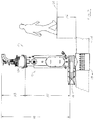
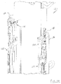
- Figure 4 shows a cable feeder system 34 making up a part of the launch tube system 10.
- Figure 4 is a partial sectional view showing a portion of the housing 26, and illustrating a cable 36 extending from an ambient environment 38 outside the housing 26 to the interior 22 of the launch tube 12. Although it is not shown extending all the way downward, it is understood that the cable 36 extends through the launch tube 12 and into the pipeline 14.
- an inside 40 of the housing 26 is in fluid communication with the interior 22 of the launch tube 12, and is therefore in fluid communication with the interior 20 of the pipeline 14.
- the cable feeder system 34 includes a first actuator arrangement 42 disposed on an outside 44 of the housing 26. It further includes a second actuator arrangement 46 disposed on the inside 40 of the housing 26.
- a seal arrangement 48 is disposed in the housing 26 between the first and second actuator arrangements 42, 46.
- actuators such as the actuators 56, 58 may be opened and closed
- pneumatic cylinders 76, 78 are used.
- the pneumatic cylinders 76, 78 are shown on either side of the actuator 56, and although not shown on the inside 40 of the housing 26, it is understood that the inside actuator 58 also includes a pair of pneumatic cylinders for opening and closing them around a cable.
- a flexible cable such as the cable 36
- a tight seal such as the seal arrangement 48.
- each of the jaws 60, 62 includes a movable track 64, 66 made up of a number of segmented links.
- One of the links 80 is partially shown in a side view in Figure 5B .
- the link 80 is generally arcuate in shape and is configured to receive a cable, and more particularly, is sized to mate with an outside of a cable, such as the cable 36.
- the movable track 64 includes two rollers 93, 95 disposed near the limits of their movement.
- the movable track 66 includes rollers 97, 99. These rollers provide support for their respective tracks 64, 66 to firmly grip the cable 36 at positions directly opposite the rollers; this is the situation for many belt or chain drive systems.
- each of the components 90, 98, 100, 102, 104 is configured as two separate pieces. This may be convenient for installing the seal arrangement 48, but is not required, and in other embodiments one or more of these components may be a single piece.
- the vent 98 includes a channel 106 disposed around an outside surface 108 of the vent 98.
- the channel 106 includes a plurality of apertures, each of which is labeled 110 for convenience that are disposed in the channel 106 and through an inside surface 112 of the vent 98.
- the secondary seal 102 includes a first side 114 and a second side 116 disposed opposite the first side 114 and adjacent to and contacting the vent 98.
- the first side 92 of the seal 90 includes an outer perimeter 118 that is formed at an angle to a bottom surface 120.
- the compression ring 100 also includes an angled surface 122 configured to mate with the perimeter 118 of the seal 90.
- the compression ring 100 and the perimeter 118 of the seal 90 are angled such that when the seal 90 is axially compressed-in a vertical direction as shown in Figure 7 -the compression ring imparts an axial force and a radial force to the seal 90.
- a force (F) is directed perpendicularly to the contacting surface 122 of the compression ring 100.
- the force (F) can be resolved into two components, and axial force component (A) and a radial force component (R). The same configuration and analysis is applicable to the secondary seal 102 and the secondary compression ring 104.
- each of the guide arrangements 142, 144 includes a plurality of elongate members.
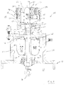
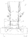
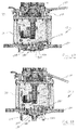
- Figure 10 shows a portion of the launch tube 12, and in particular a partial cutaway view of the chambers 28, 30.
- the first and second guide arrangements 142, 144 are at least partially deployed, and have moved downward along the launch tube 12.
- an access port 168 which may be used in the event of power failure or other anomaly in order to manually access and retrieve the guide arrangement 142 from the interior of the pipeline, which is where they are partially located when they are in their use position.
- another access port such as the access port 168, will be located at the top of the chamber 30 to provide access to the guide arrangement 144.
- a lever arm 206 which is pivotably attached to a slider bar 240 behind the clamp 188-this is explained in more detail below and illustrated in Figure 19 .
- a pivot point 208 at an end 210 of the lever arm 206 is above a pivot point 211 of a mid-portion of the lever arm 206.
- the pivot point 208 is below the pivot point 211 when the clamp 188 is in the lock position.
- the lever arm 206 is in an over-center position, which helps to secure the clamp 188 in the lock position and inhibit movement of the clamp 188 from the lock position to the release position by a backdrive force.
- Figure 14 also shows two tension springs 212, 214 which help to keep the jaws 191, 192 open when they are in the release position such as shown in Figure 13 -although only one of the springs 212 is shown in that figure.
- the interaction between the clamp 188 and the convex portion 186 of the frame 184 is such that in the locked position, pivoting of the convex portion 186 is facilitated, while translation of the convex portion 186 is inhibited.
- This configuration may be desirable when the frame 184 is attached to a very heavy object, such as a complicated inspection or repair robot. Allowing some pivoting movement reduces the stress on the frame 184.
- clamp arrangements such as the clamp arrangement 182 may allow for more or less movement of the clamped object.
- the jaws 190, 192 maintain an opening or gap between them when locked. This accommodates a cable, such as the cable 36, if the pipeline apparatus is, for example, a cabled robot-see also Figure 19 .
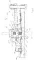
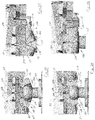
- Figure 15 shows essentially the same view as shown in Figure 13 , with several additional features illustrated-i.e., fewer of the features have been cut away as compared to Figure 13 .
- the jaws 190, 192 of the clamp 188 are shown in their entirety. Again, they are shown in the release position, with the convex portion 186 able to move freely in and out from between the jaws 190, 192.
- the jaws 190, 192 are connected to each other to effect asynchronous movement. More specifically, the jaw 190 includes a rack 216 having gear teeth 218, and the jaw 192 includes a rack 220 having gear teeth 222 configured to intermesh with the gear teeth 218. This helps to keep the movement of the jaws 190, 192 synchronous as they go between the lock and release positions-i.e. they move together.
- a slider bar 224 which moves up and down depending on whether the clamp 188 is in the lock or release position.
- the slider bar 224 includes a roller 226 that contacts an outside of the jaw 192. In the release position as shown in Figure 15 , the roller 226 is generally high on the jaw 192.
- the slider bar 224 and the associated roller 226 have moved downward.
- the slider bar 224 and roller 226 help to further secure the clamp 188 in the lock position.
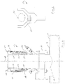
- Figure 17 shows a portion of the launch tube 12, and in particular an upper portion of the launch tube 12, including the housing 26.
- Inside the housing 26 is an actuator arrangement 46, explained in detail above in conjunction with Figure 4 .
- the clamp 188 in the locked position, with the lever arm 206 in its over-center position, and the roller 226 and its counterpart roller 228 moved downward with the slider arm 224 to further secure the clamp 188.
- the clamp 188 is disposed within the launch tube 12, it may be convenient to have an actuator operable from outside the launch tube-which in some embodiments may be an actuator disposed outside of the tube 12-that is operable to unlock the clamp 188 and move it to its release position.
- an end 230 of the lever arm 206 which is opposite the end 210, is connected to a connector arm 232.
- the connector arm 232 extends upward and is connected to a link 233 that goes through a seal arrangement 234 to the ambient environment 38 outside the launch tube 12.
- the seal arrangement 234 need not be configured like the seal arrangement 48 described above, in part because there is a rigid connector-i.e., the link 233-that goes through the housing 26, rather than the flexible cable 36 described above.
- the actuator for moving the clamp 188 from the lock position to the release position includes a release arm 236 that is pivotable upward and downward relative to the connector arm 232. Specifically, as the release arm 236 is moved downward-see Figure 18 -the connector arm 232 is also moved downward, which causes the end 230 of the lever arm 206 to move downward.
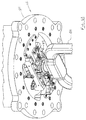
- Figure 19 shows a perspective view of the clamp arrangement 182.
- the lever arm 206 is toward the left, while a corresponding lever arm 238 is shown on the right.
- the lever arm 238 was not visible in the other drawing figures, which were partial cutaway views of the clamp arrangement 182.
- the slider bar 224 has a counterpart slider bar 240, and it is the slider bar 242 which lever arm 206 is attached.
- the jaws 190, 192 are also visible in Figure 19 , as is a portion of the connector arm 232.
- each of the slider bars 224, 240 includes two separate rollers, only the roller 226 is visible in Figure 19 .
- the perspective view shown in Figure 19 shows the robustness of the clamp arrangement 182, which provides a secure means of locking a heavy apparatus in the launch tube 12.
Landscapes
- Engineering & Computer Science (AREA)
- General Engineering & Computer Science (AREA)
- Mechanical Engineering (AREA)
- Chemical & Material Sciences (AREA)
- Combustion & Propulsion (AREA)
- Manipulator (AREA)
Applications Claiming Priority (1)
| Application Number | Priority Date | Filing Date | Title |
|---|---|---|---|
| US201562182222P | 2015-06-19 | 2015-06-19 |
Publications (2)
| Publication Number | Publication Date |
|---|---|
| EP3106734A1 true EP3106734A1 (fr) | 2016-12-21 |
| EP3106734B1 EP3106734B1 (fr) | 2020-06-03 |
Family
ID=56148222
Family Applications (4)
| Application Number | Title | Priority Date | Filing Date |
|---|---|---|---|
| EP16175314.0A Active EP3106734B1 (fr) | 2015-06-19 | 2016-06-20 | Système de lancement pour une canalisation sous pression |
| EP16175268.8A Active EP3106732B1 (fr) | 2015-06-19 | 2016-06-20 | Système de lancement pour une canalisation sous pression |
| EP16175309.0A Active EP3106733B1 (fr) | 2015-06-19 | 2016-06-20 | Système de lancement pour une canalisation sous pression |
| EP16175319.9A Ceased EP3106735A1 (fr) | 2015-06-19 | 2016-06-20 | Système de lancement pour une canalisation sous pression |
Family Applications After (3)
| Application Number | Title | Priority Date | Filing Date |
|---|---|---|---|
| EP16175268.8A Active EP3106732B1 (fr) | 2015-06-19 | 2016-06-20 | Système de lancement pour une canalisation sous pression |
| EP16175309.0A Active EP3106733B1 (fr) | 2015-06-19 | 2016-06-20 | Système de lancement pour une canalisation sous pression |
| EP16175319.9A Ceased EP3106735A1 (fr) | 2015-06-19 | 2016-06-20 | Système de lancement pour une canalisation sous pression |
Country Status (2)
| Country | Link |
|---|---|
| US (4) | US10302239B2 (fr) |
| EP (4) | EP3106734B1 (fr) |
Cited By (1)
| Publication number | Priority date | Publication date | Assignee | Title |
|---|---|---|---|---|
| EP3633260A1 (fr) * | 2018-10-05 | 2020-04-08 | Bernhard Kummert | Unité d'avance pour un système d'inspection de caméra |
Families Citing this family (9)
| Publication number | Priority date | Publication date | Assignee | Title |
|---|---|---|---|---|
| EP3356719B1 (fr) | 2015-09-29 | 2020-11-04 | Saudi Arabian Oil Company | Système automatisé de manipulation de piston racleur de pipeline |
| US11143599B2 (en) | 2018-12-03 | 2021-10-12 | Mistras Group, Inc. | Systems and methods for inspecting pipelines using a pipeline inspection robot |
| US10783623B2 (en) * | 2018-12-03 | 2020-09-22 | Mistras Group, Inc. | Systems and methods for inspecting pipelines using a robotic imaging system |
| US10890505B2 (en) | 2018-12-03 | 2021-01-12 | Mistras Group, Inc. | Systems and methods for inspecting pipelines using a robotic imaging system |
| CN109616953B (zh) * | 2018-12-19 | 2021-04-02 | 鲁西工业装备有限公司 | 一种仪表电缆敷设方法 |
| BR102019012854B1 (pt) * | 2019-06-19 | 2021-11-23 | Serviço Nacional De Aprendizagem Industrial - Departamento Regional Do Rio Grande Do Sul Senai/Rs | Sistema de lançamento de equipamento com cabo para inspeção interna e desobstrução de dutos de produção, injeção e exportação |
| US11788934B2 (en) | 2020-07-01 | 2023-10-17 | Saudi Arabian Oil Company | In-line fluid and solid sampling within flowlines |
| US11865928B2 (en) | 2021-11-24 | 2024-01-09 | Saudi Arabian Oil Company | Generating power with a conduit inspection tool |
| CN116624676B (zh) * | 2023-07-25 | 2023-09-12 | 义博通信设备集团股份有限公司 | 一种便于对接的抗压硅芯管 |
Citations (4)
| Publication number | Priority date | Publication date | Assignee | Title |
|---|---|---|---|---|
| US5823115A (en) * | 1994-09-09 | 1998-10-20 | British Gas Plc | Guiding of a pipe travelling device |
| KR101384268B1 (ko) * | 2013-09-02 | 2014-04-11 | 한국가스공사 | 배관검사로봇 런칭 및 리시빙 장치 |
| WO2014209207A1 (fr) * | 2013-06-24 | 2014-12-31 | Mont Blanc Industri Ab | Porte-bicyclette destiné à être fixé à la boule d'attelage d'un véhicule |
| US20150316195A1 (en) | 2014-05-01 | 2015-11-05 | Ulc Robotics, Inc. | System and method for pipeline maintenance |
Family Cites Families (20)
| Publication number | Priority date | Publication date | Assignee | Title |
|---|---|---|---|---|
| US4649948A (en) * | 1984-11-14 | 1987-03-17 | Leak Detective, Inc. | Entry tap valve for pressurized pipe leak detector |
| GB2230060B (en) | 1989-01-05 | 1992-11-04 | Stortford Engineering Designs | Pressure balanced retriever. |
| JP2609149B2 (ja) | 1989-05-16 | 1997-05-14 | 大阪瓦斯株式会社 | 既設ガス管継手部の活管補修装置 |
| US5025670A (en) * | 1990-05-30 | 1991-06-25 | Mcnulty George R | Means for introducing inspection equipment in active pipelines |
| GB2247055A (en) * | 1990-07-19 | 1992-02-19 | Yorkshire Water Services Ltd | Seals for use in pipeline systems |
| GB2301646B (en) | 1995-04-04 | 1998-09-16 | British Gas Plc | Apparatus for introducing into and removing from a pipe a device which is advanced and retracted by a cable |
| US5956135A (en) * | 1997-11-03 | 1999-09-21 | Quesnel; Ray J. | Pipeline inspection apparatus |
| GB9802364D0 (en) | 1998-02-05 | 1998-04-01 | British Gas Plc | Cable guide for pipes |
| US6286542B1 (en) | 1999-05-14 | 2001-09-11 | Continental Industries, Inc. | Method and article of manufacture for inserting a locator wire into a subterranean, or otherwise concealed, pressurized plastic pipeline |
| US6446662B1 (en) * | 2000-06-13 | 2002-09-10 | Dennis J. Wagner | Device for drilling or plugging a hole in a sealed fluid container or conduit wall |
| US6691734B2 (en) | 2000-10-10 | 2004-02-17 | Sempra Fiber Links | Methods and systems for installing cable and conduit in pipelines |
| US20020158239A1 (en) | 2001-03-30 | 2002-10-31 | Nkf Kabel B.V. | Optical cable installation with mini-bend reduction |
| US20040006448A1 (en) | 2002-07-02 | 2004-01-08 | Penza G. Gregory | Apparatus and method for pipeline inspection |
| US6848541B2 (en) | 2002-07-11 | 2005-02-01 | Nkf Kabel B.V. | Optical cable installation with cable lubricator |
| US6899138B2 (en) * | 2002-12-09 | 2005-05-31 | Philip L. Lundman | Flexible emergency gas pipeline plug |
| US7551197B2 (en) | 2005-09-08 | 2009-06-23 | Ulc Robotics, Inc. | Pipeline inspection system |
| JP5068683B2 (ja) | 2008-03-28 | 2012-11-07 | 三井造船株式会社 | 管内調査システム及び管内調査方法。 |
| AT506686B1 (de) * | 2008-05-05 | 2010-04-15 | Kuebel Johann Ing | Kabelführungselement |
| US20100236639A1 (en) | 2009-02-20 | 2010-09-23 | Ulc Robotics, Inc. | System And Method For Accessing A Pressurized Gas Pipeline |
| US20140246824A1 (en) * | 2013-03-02 | 2014-09-04 | Andrew P. Fiegener | Vise with Bi-directional Arms |
-
2016
- 2016-06-20 EP EP16175314.0A patent/EP3106734B1/fr active Active
- 2016-06-20 US US15/187,095 patent/US10302239B2/en active Active
- 2016-06-20 US US15/187,247 patent/US10302240B2/en active Active
- 2016-06-20 EP EP16175268.8A patent/EP3106732B1/fr active Active
- 2016-06-20 US US15/187,236 patent/US10132440B2/en active Active
- 2016-06-20 EP EP16175309.0A patent/EP3106733B1/fr active Active
- 2016-06-20 US US15/187,110 patent/US10295106B2/en active Active
- 2016-06-20 EP EP16175319.9A patent/EP3106735A1/fr not_active Ceased
Patent Citations (4)
| Publication number | Priority date | Publication date | Assignee | Title |
|---|---|---|---|---|
| US5823115A (en) * | 1994-09-09 | 1998-10-20 | British Gas Plc | Guiding of a pipe travelling device |
| WO2014209207A1 (fr) * | 2013-06-24 | 2014-12-31 | Mont Blanc Industri Ab | Porte-bicyclette destiné à être fixé à la boule d'attelage d'un véhicule |
| KR101384268B1 (ko) * | 2013-09-02 | 2014-04-11 | 한국가스공사 | 배관검사로봇 런칭 및 리시빙 장치 |
| US20150316195A1 (en) | 2014-05-01 | 2015-11-05 | Ulc Robotics, Inc. | System and method for pipeline maintenance |
Cited By (1)
| Publication number | Priority date | Publication date | Assignee | Title |
|---|---|---|---|---|
| EP3633260A1 (fr) * | 2018-10-05 | 2020-04-08 | Bernhard Kummert | Unité d'avance pour un système d'inspection de caméra |
Also Published As
| Publication number | Publication date |
|---|---|
| EP3106732B1 (fr) | 2019-04-03 |
| US20160369931A1 (en) | 2016-12-22 |
| EP3106735A1 (fr) | 2016-12-21 |
| US20160369932A1 (en) | 2016-12-22 |
| US20160369933A1 (en) | 2016-12-22 |
| EP3106734B1 (fr) | 2020-06-03 |
| EP3106732A1 (fr) | 2016-12-21 |
| EP3106733B1 (fr) | 2019-05-08 |
| US10295106B2 (en) | 2019-05-21 |
| US10302239B2 (en) | 2019-05-28 |
| EP3106733A1 (fr) | 2016-12-21 |
| US20160369934A1 (en) | 2016-12-22 |
| US10302240B2 (en) | 2019-05-28 |
| US10132440B2 (en) | 2018-11-20 |
Similar Documents
| Publication | Publication Date | Title |
|---|---|---|
| EP3106734B1 (fr) | Système de lancement pour une canalisation sous pression | |
| US6305720B1 (en) | Remote articulated connector | |
| US11590543B2 (en) | Pipeline maintenance and inspection vehicle | |
| US8430260B2 (en) | Closure for a vessel | |
| CA2238588C (fr) | Systeme et methode pour joindre deux appareils dont l'un peut se deplacer par rapport a l'autre, notamment dans les installations sous-marines | |
| CN107429867A (zh) | 一种连接两个流体导管的连接装置 | |
| EP2635836B1 (fr) | Dispositif de raccordement destiné à se raccorder à au moins une canalisation | |
| US4142740A (en) | Quick disconnect coupler | |
| CN104903634A (zh) | 具有可枢转安装的上护套和下护套的夹管阀 | |
| WO2017194066A1 (fr) | Module de flottabilité, pince pour le module de flottabilité, et procédé de montage du module de flottabilité sur un tuyau sous-marin | |
| US10919118B2 (en) | Ultrasonic scanner for pipeline use | |
| NL2007751C2 (en) | Method and device for coupling floating pipe sections. | |
| WO2016062661A1 (fr) | Ensemble et procédé d'entraînement de racleur | |
| WO1997011301A1 (fr) | Dispositif de raccordement a colliers de serrage | |
| RU2281892C2 (ru) | Устройство отвода коммуникаций с разъемным соединением | |
| EP3234432B1 (fr) | Ensemble de couplage pour transporter du gaz pressurisé avec système de libération d'urgence | |
| EP4334615A1 (fr) | Appareil et procédé pour accoupler des sections de tube dans une masse d'eau et système de jonction pour relier des sections de tube dans la masse d'eau | |
| EP3350493B1 (fr) | Limiteur de courbure | |
| IT202100029537A1 (it) | “Gruppo di raccordo idraulico con unità valvolari flangiate e dispositivo di connessione a sgancio rapido comandato elettricamente.” | |
| WO1980001833A1 (fr) | Dispositif d'accouplement a ouverture rapide |
Legal Events
| Date | Code | Title | Description |
|---|---|---|---|
| PUAI | Public reference made under article 153(3) epc to a published international application that has entered the european phase |
Free format text: ORIGINAL CODE: 0009012 |
|
| STAA | Information on the status of an ep patent application or granted ep patent |
Free format text: STATUS: THE APPLICATION HAS BEEN PUBLISHED |
|
| AK | Designated contracting states |
Kind code of ref document: A1 Designated state(s): AL AT BE BG CH CY CZ DE DK EE ES FI FR GB GR HR HU IE IS IT LI LT LU LV MC MK MT NL NO PL PT RO RS SE SI SK SM TR |
|
| AX | Request for extension of the european patent |
Extension state: BA ME |
|
| STAA | Information on the status of an ep patent application or granted ep patent |
Free format text: STATUS: REQUEST FOR EXAMINATION WAS MADE |
|
| 17P | Request for examination filed |
Effective date: 20170619 |
|
| RBV | Designated contracting states (corrected) |
Designated state(s): AL AT BE BG CH CY CZ DE DK EE ES FI FR GB GR HR HU IE IS IT LI LT LU LV MC MK MT NL NO PL PT RO RS SE SI SK SM TR |
|
| STAA | Information on the status of an ep patent application or granted ep patent |
Free format text: STATUS: EXAMINATION IS IN PROGRESS |
|
| 17Q | First examination report despatched |
Effective date: 20181114 |
|
| GRAP | Despatch of communication of intention to grant a patent |
Free format text: ORIGINAL CODE: EPIDOSNIGR1 |
|
| STAA | Information on the status of an ep patent application or granted ep patent |
Free format text: STATUS: GRANT OF PATENT IS INTENDED |
|
| INTG | Intention to grant announced |
Effective date: 20191220 |
|
| RIN1 | Information on inventor provided before grant (corrected) |
Inventor name: PASSARETTI, MICHAEL Inventor name: FELDMAN, ERIC S. Inventor name: ANTANAVIGE, DAVID Inventor name: PENZA, G. GREGORY Inventor name: KODADEK, ROBERT E. Inventor name: LAGOSZ-SINCLAIR, BENJAMIN |
|
| GRAJ | Information related to disapproval of communication of intention to grant by the applicant or resumption of examination proceedings by the epo deleted |
Free format text: ORIGINAL CODE: EPIDOSDIGR1 |
|
| STAA | Information on the status of an ep patent application or granted ep patent |
Free format text: STATUS: EXAMINATION IS IN PROGRESS |
|
| GRAR | Information related to intention to grant a patent recorded |
Free format text: ORIGINAL CODE: EPIDOSNIGR71 |
|
| GRAS | Grant fee paid |
Free format text: ORIGINAL CODE: EPIDOSNIGR3 |
|
| STAA | Information on the status of an ep patent application or granted ep patent |
Free format text: STATUS: GRANT OF PATENT IS INTENDED |
|
| GRAA | (expected) grant |
Free format text: ORIGINAL CODE: 0009210 |
|
| STAA | Information on the status of an ep patent application or granted ep patent |
Free format text: STATUS: THE PATENT HAS BEEN GRANTED |
|
| INTC | Intention to grant announced (deleted) | ||
| INTG | Intention to grant announced |
Effective date: 20200423 |
|
| AK | Designated contracting states |
Kind code of ref document: B1 Designated state(s): AL AT BE BG CH CY CZ DE DK EE ES FI FR GB GR HR HU IE IS IT LI LT LU LV MC MK MT NL NO PL PT RO RS SE SI SK SM TR |
|
| REG | Reference to a national code |
Ref country code: GB Ref legal event code: FG4D |
|
| REG | Reference to a national code |
Ref country code: CH Ref legal event code: EP Ref country code: AT Ref legal event code: REF Ref document number: 1277368 Country of ref document: AT Kind code of ref document: T Effective date: 20200615 |
|
| REG | Reference to a national code |
Ref country code: DE Ref legal event code: R096 Ref document number: 602016037369 Country of ref document: DE |
|
| REG | Reference to a national code |
Ref country code: LT Ref legal event code: MG4D |
|
| PG25 | Lapsed in a contracting state [announced via postgrant information from national office to epo] |
Ref country code: LT Free format text: LAPSE BECAUSE OF FAILURE TO SUBMIT A TRANSLATION OF THE DESCRIPTION OR TO PAY THE FEE WITHIN THE PRESCRIBED TIME-LIMIT Effective date: 20200603 Ref country code: NO Free format text: LAPSE BECAUSE OF FAILURE TO SUBMIT A TRANSLATION OF THE DESCRIPTION OR TO PAY THE FEE WITHIN THE PRESCRIBED TIME-LIMIT Effective date: 20200903 Ref country code: SE Free format text: LAPSE BECAUSE OF FAILURE TO SUBMIT A TRANSLATION OF THE DESCRIPTION OR TO PAY THE FEE WITHIN THE PRESCRIBED TIME-LIMIT Effective date: 20200603 Ref country code: FI Free format text: LAPSE BECAUSE OF FAILURE TO SUBMIT A TRANSLATION OF THE DESCRIPTION OR TO PAY THE FEE WITHIN THE PRESCRIBED TIME-LIMIT Effective date: 20200603 Ref country code: GR Free format text: LAPSE BECAUSE OF FAILURE TO SUBMIT A TRANSLATION OF THE DESCRIPTION OR TO PAY THE FEE WITHIN THE PRESCRIBED TIME-LIMIT Effective date: 20200904 |
|
| REG | Reference to a national code |
Ref country code: NL Ref legal event code: MP Effective date: 20200603 |
|
| PG25 | Lapsed in a contracting state [announced via postgrant information from national office to epo] |
Ref country code: RS Free format text: LAPSE BECAUSE OF FAILURE TO SUBMIT A TRANSLATION OF THE DESCRIPTION OR TO PAY THE FEE WITHIN THE PRESCRIBED TIME-LIMIT Effective date: 20200603 Ref country code: LV Free format text: LAPSE BECAUSE OF FAILURE TO SUBMIT A TRANSLATION OF THE DESCRIPTION OR TO PAY THE FEE WITHIN THE PRESCRIBED TIME-LIMIT Effective date: 20200603 Ref country code: BG Free format text: LAPSE BECAUSE OF FAILURE TO SUBMIT A TRANSLATION OF THE DESCRIPTION OR TO PAY THE FEE WITHIN THE PRESCRIBED TIME-LIMIT Effective date: 20200903 Ref country code: HR Free format text: LAPSE BECAUSE OF FAILURE TO SUBMIT A TRANSLATION OF THE DESCRIPTION OR TO PAY THE FEE WITHIN THE PRESCRIBED TIME-LIMIT Effective date: 20200603 |
|
| REG | Reference to a national code |
Ref country code: AT Ref legal event code: MK05 Ref document number: 1277368 Country of ref document: AT Kind code of ref document: T Effective date: 20200603 |
|
| PG25 | Lapsed in a contracting state [announced via postgrant information from national office to epo] |
Ref country code: NL Free format text: LAPSE BECAUSE OF FAILURE TO SUBMIT A TRANSLATION OF THE DESCRIPTION OR TO PAY THE FEE WITHIN THE PRESCRIBED TIME-LIMIT Effective date: 20200603 Ref country code: AL Free format text: LAPSE BECAUSE OF FAILURE TO SUBMIT A TRANSLATION OF THE DESCRIPTION OR TO PAY THE FEE WITHIN THE PRESCRIBED TIME-LIMIT Effective date: 20200603 |
|
| REG | Reference to a national code |
Ref country code: DE Ref legal event code: R119 Ref document number: 602016037369 Country of ref document: DE |
|
| PG25 | Lapsed in a contracting state [announced via postgrant information from national office to epo] |
Ref country code: CZ Free format text: LAPSE BECAUSE OF FAILURE TO SUBMIT A TRANSLATION OF THE DESCRIPTION OR TO PAY THE FEE WITHIN THE PRESCRIBED TIME-LIMIT Effective date: 20200603 Ref country code: ES Free format text: LAPSE BECAUSE OF FAILURE TO SUBMIT A TRANSLATION OF THE DESCRIPTION OR TO PAY THE FEE WITHIN THE PRESCRIBED TIME-LIMIT Effective date: 20200603 Ref country code: PT Free format text: LAPSE BECAUSE OF FAILURE TO SUBMIT A TRANSLATION OF THE DESCRIPTION OR TO PAY THE FEE WITHIN THE PRESCRIBED TIME-LIMIT Effective date: 20201006 Ref country code: RO Free format text: LAPSE BECAUSE OF FAILURE TO SUBMIT A TRANSLATION OF THE DESCRIPTION OR TO PAY THE FEE WITHIN THE PRESCRIBED TIME-LIMIT Effective date: 20200603 Ref country code: IT Free format text: LAPSE BECAUSE OF FAILURE TO SUBMIT A TRANSLATION OF THE DESCRIPTION OR TO PAY THE FEE WITHIN THE PRESCRIBED TIME-LIMIT Effective date: 20200603 Ref country code: SM Free format text: LAPSE BECAUSE OF FAILURE TO SUBMIT A TRANSLATION OF THE DESCRIPTION OR TO PAY THE FEE WITHIN THE PRESCRIBED TIME-LIMIT Effective date: 20200603 Ref country code: AT Free format text: LAPSE BECAUSE OF FAILURE TO SUBMIT A TRANSLATION OF THE DESCRIPTION OR TO PAY THE FEE WITHIN THE PRESCRIBED TIME-LIMIT Effective date: 20200603 Ref country code: EE Free format text: LAPSE BECAUSE OF FAILURE TO SUBMIT A TRANSLATION OF THE DESCRIPTION OR TO PAY THE FEE WITHIN THE PRESCRIBED TIME-LIMIT Effective date: 20200603 |
|
| REG | Reference to a national code |
Ref country code: CH Ref legal event code: PL |
|
| PG25 | Lapsed in a contracting state [announced via postgrant information from national office to epo] |
Ref country code: SK Free format text: LAPSE BECAUSE OF FAILURE TO SUBMIT A TRANSLATION OF THE DESCRIPTION OR TO PAY THE FEE WITHIN THE PRESCRIBED TIME-LIMIT Effective date: 20200603 Ref country code: PL Free format text: LAPSE BECAUSE OF FAILURE TO SUBMIT A TRANSLATION OF THE DESCRIPTION OR TO PAY THE FEE WITHIN THE PRESCRIBED TIME-LIMIT Effective date: 20200603 Ref country code: IS Free format text: LAPSE BECAUSE OF FAILURE TO SUBMIT A TRANSLATION OF THE DESCRIPTION OR TO PAY THE FEE WITHIN THE PRESCRIBED TIME-LIMIT Effective date: 20201003 |
|
| PG25 | Lapsed in a contracting state [announced via postgrant information from national office to epo] |
Ref country code: LU Free format text: LAPSE BECAUSE OF NON-PAYMENT OF DUE FEES Effective date: 20200620 Ref country code: MC Free format text: LAPSE BECAUSE OF FAILURE TO SUBMIT A TRANSLATION OF THE DESCRIPTION OR TO PAY THE FEE WITHIN THE PRESCRIBED TIME-LIMIT Effective date: 20200603 |
|
| PLBE | No opposition filed within time limit |
Free format text: ORIGINAL CODE: 0009261 |
|
| STAA | Information on the status of an ep patent application or granted ep patent |
Free format text: STATUS: NO OPPOSITION FILED WITHIN TIME LIMIT |
|
| REG | Reference to a national code |
Ref country code: BE Ref legal event code: MM Effective date: 20200630 |
|
| PG25 | Lapsed in a contracting state [announced via postgrant information from national office to epo] |
Ref country code: LI Free format text: LAPSE BECAUSE OF NON-PAYMENT OF DUE FEES Effective date: 20200630 Ref country code: DK Free format text: LAPSE BECAUSE OF FAILURE TO SUBMIT A TRANSLATION OF THE DESCRIPTION OR TO PAY THE FEE WITHIN THE PRESCRIBED TIME-LIMIT Effective date: 20200603 Ref country code: CH Free format text: LAPSE BECAUSE OF NON-PAYMENT OF DUE FEES Effective date: 20200630 Ref country code: FR Free format text: LAPSE BECAUSE OF NON-PAYMENT OF DUE FEES Effective date: 20200803 Ref country code: IE Free format text: LAPSE BECAUSE OF NON-PAYMENT OF DUE FEES Effective date: 20200620 |
|
| 26N | No opposition filed |
Effective date: 20210304 |
|
| PG25 | Lapsed in a contracting state [announced via postgrant information from national office to epo] |
Ref country code: SI Free format text: LAPSE BECAUSE OF FAILURE TO SUBMIT A TRANSLATION OF THE DESCRIPTION OR TO PAY THE FEE WITHIN THE PRESCRIBED TIME-LIMIT Effective date: 20200603 Ref country code: DE Free format text: LAPSE BECAUSE OF NON-PAYMENT OF DUE FEES Effective date: 20210101 Ref country code: BE Free format text: LAPSE BECAUSE OF NON-PAYMENT OF DUE FEES Effective date: 20200630 |
|
| PG25 | Lapsed in a contracting state [announced via postgrant information from national office to epo] |
Ref country code: TR Free format text: LAPSE BECAUSE OF FAILURE TO SUBMIT A TRANSLATION OF THE DESCRIPTION OR TO PAY THE FEE WITHIN THE PRESCRIBED TIME-LIMIT Effective date: 20200603 Ref country code: MT Free format text: LAPSE BECAUSE OF FAILURE TO SUBMIT A TRANSLATION OF THE DESCRIPTION OR TO PAY THE FEE WITHIN THE PRESCRIBED TIME-LIMIT Effective date: 20200603 Ref country code: CY Free format text: LAPSE BECAUSE OF FAILURE TO SUBMIT A TRANSLATION OF THE DESCRIPTION OR TO PAY THE FEE WITHIN THE PRESCRIBED TIME-LIMIT Effective date: 20200603 |
|
| PG25 | Lapsed in a contracting state [announced via postgrant information from national office to epo] |
Ref country code: MK Free format text: LAPSE BECAUSE OF FAILURE TO SUBMIT A TRANSLATION OF THE DESCRIPTION OR TO PAY THE FEE WITHIN THE PRESCRIBED TIME-LIMIT Effective date: 20200603 |
|
| PGFP | Annual fee paid to national office [announced via postgrant information from national office to epo] |
Ref country code: GB Payment date: 20230828 Year of fee payment: 8 |