EP3106618A1 - Hot gas path component cooling system having a particle collection chamber - Google Patents
Hot gas path component cooling system having a particle collection chamber Download PDFInfo
- Publication number
- EP3106618A1 EP3106618A1 EP16174145.9A EP16174145A EP3106618A1 EP 3106618 A1 EP3106618 A1 EP 3106618A1 EP 16174145 A EP16174145 A EP 16174145A EP 3106618 A1 EP3106618 A1 EP 3106618A1
- Authority
- EP
- European Patent Office
- Prior art keywords
- passage
- hot gas
- cooling system
- substrate
- gas path
- Prior art date
- Legal status (The legal status is an assumption and is not a legal conclusion. Google has not performed a legal analysis and makes no representation as to the accuracy of the status listed.)
- Granted
Links
- 238000001816 cooling Methods 0.000 title claims abstract description 75
- 239000002245 particle Substances 0.000 title claims abstract description 21
- 239000000758 substrate Substances 0.000 claims abstract description 56
- 239000012809 cooling fluid Substances 0.000 claims abstract description 23
- 230000001154 acute effect Effects 0.000 claims abstract description 18
- 238000004891 communication Methods 0.000 claims description 8
- 239000012530 fluid Substances 0.000 claims description 8
- 239000007789 gas Substances 0.000 description 138
- 238000000576 coating method Methods 0.000 description 31
- 239000011248 coating agent Substances 0.000 description 27
- 238000000034 method Methods 0.000 description 16
- 230000006870 function Effects 0.000 description 12
- 239000000463 material Substances 0.000 description 11
- 230000008569 process Effects 0.000 description 9
- 230000001965 increasing effect Effects 0.000 description 6
- 238000003754 machining Methods 0.000 description 6
- 239000007921 spray Substances 0.000 description 6
- 230000000712 assembly Effects 0.000 description 5
- 238000000429 assembly Methods 0.000 description 5
- 238000000151 deposition Methods 0.000 description 4
- 239000000446 fuel Substances 0.000 description 4
- 239000012720 thermal barrier coating Substances 0.000 description 4
- XLYOFNOQVPJJNP-UHFFFAOYSA-N water Substances O XLYOFNOQVPJJNP-UHFFFAOYSA-N 0.000 description 4
- 238000002485 combustion reaction Methods 0.000 description 3
- 150000002500 ions Chemical class 0.000 description 3
- 238000005507 spraying Methods 0.000 description 3
- 229910000601 superalloy Inorganic materials 0.000 description 3
- 238000012546 transfer Methods 0.000 description 3
- MCMNRKCIXSYSNV-UHFFFAOYSA-N Zirconium dioxide Chemical compound O=[Zr]=O MCMNRKCIXSYSNV-UHFFFAOYSA-N 0.000 description 2
- 239000011153 ceramic matrix composite Substances 0.000 description 2
- 230000008859 change Effects 0.000 description 2
- 230000005465 channeling Effects 0.000 description 2
- 230000008021 deposition Effects 0.000 description 2
- 238000010286 high velocity air fuel Methods 0.000 description 2
- 238000007749 high velocity oxygen fuel spraying Methods 0.000 description 2
- 239000007788 liquid Substances 0.000 description 2
- 239000000203 mixture Substances 0.000 description 2
- 238000007750 plasma spraying Methods 0.000 description 2
- 229910052688 Gadolinium Inorganic materials 0.000 description 1
- 229910052779 Neodymium Inorganic materials 0.000 description 1
- 229910000943 NiAl Inorganic materials 0.000 description 1
- NPXOKRUENSOPAO-UHFFFAOYSA-N Raney nickel Chemical compound [Al].[Ni] NPXOKRUENSOPAO-UHFFFAOYSA-N 0.000 description 1
- 229910052769 Ytterbium Inorganic materials 0.000 description 1
- 239000003082 abrasive agent Substances 0.000 description 1
- 229910045601 alloy Inorganic materials 0.000 description 1
- 239000000956 alloy Substances 0.000 description 1
- WYTGDNHDOZPMIW-RCBQFDQVSA-N alstonine Natural products C1=CC2=C3C=CC=CC3=NC2=C2N1C[C@H]1[C@H](C)OC=C(C(=O)OC)[C@H]1C2 WYTGDNHDOZPMIW-RCBQFDQVSA-N 0.000 description 1
- 230000004888 barrier function Effects 0.000 description 1
- 239000011324 bead Substances 0.000 description 1
- 230000000903 blocking effect Effects 0.000 description 1
- 238000005266 casting Methods 0.000 description 1
- 239000000919 ceramic Substances 0.000 description 1
- 238000005520 cutting process Methods 0.000 description 1
- 238000005137 deposition process Methods 0.000 description 1
- 238000013461 design Methods 0.000 description 1
- 238000007772 electroless plating Methods 0.000 description 1
- 238000005328 electron beam physical vapour deposition Methods 0.000 description 1
- 238000009713 electroplating Methods 0.000 description 1
- 230000002708 enhancing effect Effects 0.000 description 1
- 230000007613 environmental effect Effects 0.000 description 1
- 230000003628 erosive effect Effects 0.000 description 1
- 230000008020 evaporation Effects 0.000 description 1
- 238000001704 evaporation Methods 0.000 description 1
- 239000002223 garnet Substances 0.000 description 1
- 239000011521 glass Substances 0.000 description 1
- 230000003116 impacting effect Effects 0.000 description 1
- 239000011261 inert gas Substances 0.000 description 1
- 239000001995 intermetallic alloy Substances 0.000 description 1
- 229910052747 lanthanoid Inorganic materials 0.000 description 1
- 150000002602 lanthanoids Chemical class 0.000 description 1
- 229910052746 lanthanum Inorganic materials 0.000 description 1
- 238000004519 manufacturing process Methods 0.000 description 1
- 230000004048 modification Effects 0.000 description 1
- 238000012986 modification Methods 0.000 description 1
- 230000003647 oxidation Effects 0.000 description 1
- 238000007254 oxidation reaction Methods 0.000 description 1
- TWNQGVIAIRXVLR-UHFFFAOYSA-N oxo(oxoalumanyloxy)alumane Chemical compound O=[Al]O[Al]=O TWNQGVIAIRXVLR-UHFFFAOYSA-N 0.000 description 1
- 238000000206 photolithography Methods 0.000 description 1
- 238000005240 physical vapour deposition Methods 0.000 description 1
- 238000010248 power generation Methods 0.000 description 1
- 230000001681 protective effect Effects 0.000 description 1
- HBMJWWWQQXIZIP-UHFFFAOYSA-N silicon carbide Chemical compound [Si+]#[C-] HBMJWWWQQXIZIP-UHFFFAOYSA-N 0.000 description 1
- 229910010271 silicon carbide Inorganic materials 0.000 description 1
- 238000004544 sputter deposition Methods 0.000 description 1
- -1 steam Substances 0.000 description 1
- 239000000126 substance Substances 0.000 description 1
- 230000007704 transition Effects 0.000 description 1
- 238000011144 upstream manufacturing Methods 0.000 description 1
- 238000005019 vapor deposition process Methods 0.000 description 1
- 229910001233 yttria-stabilized zirconia Inorganic materials 0.000 description 1
Images


Classifications
-
- F—MECHANICAL ENGINEERING; LIGHTING; HEATING; WEAPONS; BLASTING
- F02—COMBUSTION ENGINES; HOT-GAS OR COMBUSTION-PRODUCT ENGINE PLANTS
- F02C—GAS-TURBINE PLANTS; AIR INTAKES FOR JET-PROPULSION PLANTS; CONTROLLING FUEL SUPPLY IN AIR-BREATHING JET-PROPULSION PLANTS
- F02C7/00—Features, components parts, details or accessories, not provided for in, or of interest apart form groups F02C1/00 - F02C6/00; Air intakes for jet-propulsion plants
- F02C7/12—Cooling of plants
- F02C7/16—Cooling of plants characterised by cooling medium
- F02C7/18—Cooling of plants characterised by cooling medium the medium being gaseous, e.g. air
-
- F—MECHANICAL ENGINEERING; LIGHTING; HEATING; WEAPONS; BLASTING
- F01—MACHINES OR ENGINES IN GENERAL; ENGINE PLANTS IN GENERAL; STEAM ENGINES
- F01D—NON-POSITIVE DISPLACEMENT MACHINES OR ENGINES, e.g. STEAM TURBINES
- F01D5/00—Blades; Blade-carrying members; Heating, heat-insulating, cooling or antivibration means on the blades or the members
- F01D5/12—Blades
- F01D5/14—Form or construction
- F01D5/18—Hollow blades, i.e. blades with cooling or heating channels or cavities; Heating, heat-insulating or cooling means on blades
- F01D5/187—Convection cooling
- F01D5/188—Convection cooling with an insert in the blade cavity to guide the cooling fluid, e.g. forming a separation wall
-
- F—MECHANICAL ENGINEERING; LIGHTING; HEATING; WEAPONS; BLASTING
- F02—COMBUSTION ENGINES; HOT-GAS OR COMBUSTION-PRODUCT ENGINE PLANTS
- F02C—GAS-TURBINE PLANTS; AIR INTAKES FOR JET-PROPULSION PLANTS; CONTROLLING FUEL SUPPLY IN AIR-BREATHING JET-PROPULSION PLANTS
- F02C3/00—Gas-turbine plants characterised by the use of combustion products as the working fluid
- F02C3/04—Gas-turbine plants characterised by the use of combustion products as the working fluid having a turbine driving a compressor
-
- F—MECHANICAL ENGINEERING; LIGHTING; HEATING; WEAPONS; BLASTING
- F02—COMBUSTION ENGINES; HOT-GAS OR COMBUSTION-PRODUCT ENGINE PLANTS
- F02C—GAS-TURBINE PLANTS; AIR INTAKES FOR JET-PROPULSION PLANTS; CONTROLLING FUEL SUPPLY IN AIR-BREATHING JET-PROPULSION PLANTS
- F02C7/00—Features, components parts, details or accessories, not provided for in, or of interest apart form groups F02C1/00 - F02C6/00; Air intakes for jet-propulsion plants
- F02C7/04—Air intakes for gas-turbine plants or jet-propulsion plants
- F02C7/05—Air intakes for gas-turbine plants or jet-propulsion plants having provisions for obviating the penetration of damaging objects or particles
- F02C7/052—Air intakes for gas-turbine plants or jet-propulsion plants having provisions for obviating the penetration of damaging objects or particles with dust-separation devices
-
- F—MECHANICAL ENGINEERING; LIGHTING; HEATING; WEAPONS; BLASTING
- F02—COMBUSTION ENGINES; HOT-GAS OR COMBUSTION-PRODUCT ENGINE PLANTS
- F02C—GAS-TURBINE PLANTS; AIR INTAKES FOR JET-PROPULSION PLANTS; CONTROLLING FUEL SUPPLY IN AIR-BREATHING JET-PROPULSION PLANTS
- F02C7/00—Features, components parts, details or accessories, not provided for in, or of interest apart form groups F02C1/00 - F02C6/00; Air intakes for jet-propulsion plants
- F02C7/12—Cooling of plants
- F02C7/14—Cooling of plants of fluids in the plant, e.g. lubricant or fuel
- F02C7/141—Cooling of plants of fluids in the plant, e.g. lubricant or fuel of working fluid
-
- F—MECHANICAL ENGINEERING; LIGHTING; HEATING; WEAPONS; BLASTING
- F05—INDEXING SCHEMES RELATING TO ENGINES OR PUMPS IN VARIOUS SUBCLASSES OF CLASSES F01-F04
- F05D—INDEXING SCHEME FOR ASPECTS RELATING TO NON-POSITIVE-DISPLACEMENT MACHINES OR ENGINES, GAS-TURBINES OR JET-PROPULSION PLANTS
- F05D2240/00—Components
- F05D2240/80—Platforms for stationary or moving blades
- F05D2240/81—Cooled platforms
-
- F—MECHANICAL ENGINEERING; LIGHTING; HEATING; WEAPONS; BLASTING
- F05—INDEXING SCHEMES RELATING TO ENGINES OR PUMPS IN VARIOUS SUBCLASSES OF CLASSES F01-F04
- F05D—INDEXING SCHEME FOR ASPECTS RELATING TO NON-POSITIVE-DISPLACEMENT MACHINES OR ENGINES, GAS-TURBINES OR JET-PROPULSION PLANTS
- F05D2260/00—Function
- F05D2260/20—Heat transfer, e.g. cooling
- F05D2260/202—Heat transfer, e.g. cooling by film cooling
-
- F—MECHANICAL ENGINEERING; LIGHTING; HEATING; WEAPONS; BLASTING
- F05—INDEXING SCHEMES RELATING TO ENGINES OR PUMPS IN VARIOUS SUBCLASSES OF CLASSES F01-F04
- F05D—INDEXING SCHEME FOR ASPECTS RELATING TO NON-POSITIVE-DISPLACEMENT MACHINES OR ENGINES, GAS-TURBINES OR JET-PROPULSION PLANTS
- F05D2260/00—Function
- F05D2260/20—Heat transfer, e.g. cooling
- F05D2260/204—Heat transfer, e.g. cooling by the use of microcircuits
-
- F—MECHANICAL ENGINEERING; LIGHTING; HEATING; WEAPONS; BLASTING
- F05—INDEXING SCHEMES RELATING TO ENGINES OR PUMPS IN VARIOUS SUBCLASSES OF CLASSES F01-F04
- F05D—INDEXING SCHEME FOR ASPECTS RELATING TO NON-POSITIVE-DISPLACEMENT MACHINES OR ENGINES, GAS-TURBINES OR JET-PROPULSION PLANTS
- F05D2260/00—Function
- F05D2260/60—Fluid transfer
- F05D2260/607—Preventing clogging or obstruction of flow paths by dirt, dust, or foreign particles
-
- Y—GENERAL TAGGING OF NEW TECHNOLOGICAL DEVELOPMENTS; GENERAL TAGGING OF CROSS-SECTIONAL TECHNOLOGIES SPANNING OVER SEVERAL SECTIONS OF THE IPC; TECHNICAL SUBJECTS COVERED BY FORMER USPC CROSS-REFERENCE ART COLLECTIONS [XRACs] AND DIGESTS
- Y02—TECHNOLOGIES OR APPLICATIONS FOR MITIGATION OR ADAPTATION AGAINST CLIMATE CHANGE
- Y02T—CLIMATE CHANGE MITIGATION TECHNOLOGIES RELATED TO TRANSPORTATION
- Y02T50/00—Aeronautics or air transport
- Y02T50/60—Efficient propulsion technologies, e.g. for aircraft
Definitions
- the field of the present disclosure relates generally to turbine engines, and more particularly to systems for cooling hot gas path components in turbine engines.
- Gas turbine systems are widely utilized in fields such as power generation.
- a conventional gas turbine system includes a compressor, a combustor, and a turbine.
- various components in the system are subjected to high temperature flows, which can cause the components to fail. Since higher temperature flows generally result in increased performance, efficiency, and power output of the gas turbine system and are thus desired in a gas turbine system, the components that are subjected to high temperature flows must be cooled to allow the gas turbine system to operate with flows at increased temperatures.
- cooling components that are subjected to high temperature flows.
- These components are typically known as hot gas path components.
- a series of internal cooling passages may be formed in a hot gas path component.
- a cooling fluid may be provided to the passages from a plenum, and the cooling fluid may flow through the passages, cooling the hot gas path component substrate and coatings.
- the cooling fluid can be contaminated with various types of particles, which can cause blockage of the internal cooling passages, or serpentines formed in the hot gas path component that is cooled with the cooling fluid. Such blockage can shorten the life of these components.
- a cooling system for a hot gas path component includes a substrate comprising an outer surface and an inner surface.
- the inner surface defines at least one interior space.
- the cooling system includes a passage extending between the outer surface and the inner surface of the substrate.
- the cooling system includes an access passage formed in the substrate and extending from the outer surface to the at least one inner space.
- the access passage is formed at a first acute angle to the passage.
- the access passage includes a particle collection chamber.
- the access passage is configured to channel a cooling fluid to the passage.
- the passage is configured to channel the cooling fluid therethrough to cool the substrate.
- a gas turbine engine in another aspect, includes a compressor, a turbine coupled to the compressor, and a hot gas path component disposed in a least one of the compressor and the turbine.
- the hot gas path component includes a substrate comprising an outer surface and an inner surface. The inner surface defines at least one interior space.
- the hot gas path component also includes a passage extending between the outer surface and the inner surface of the substrate.
- the hot gas path component includes an access passage formed in the substrate and extending from the outer surface to the at least one inner space.
- the access passage is formed at a first acute angle to the passage.
- the access passage includes a particle collection chamber.
- the access passage is configured to channel a cooling fluid to the passage.
- the passage is configured to channel the cooling fluid therethrough to cool the substrate.
- Approximating language may be applied to modify any quantitative representation that could permissibly vary without resulting in a change in the basic function to which it is related. Accordingly, a value modified by a term or terms, such as “about”, “approximately”, and “substantially”, are not to be limited to the precise value specified. In at least some instances, the approximating language may correspond to the precision of an instrument for measuring the value.
- range limitations may be combined and/or interchanged; such ranges are identified and include all the sub-ranges contained therein unless context or language indicates otherwise.
- FIG. 1 is a schematic view of a rotary machine, i.e., a turbomachine, and more specifically, a turbine engine.
- the turbine engine is a gas turbine engine 10.
- the rotary machine is any other turbine engine and/or rotary machine, including, without limitation, a steam turbine engine, a centrifugal compressor, and a turbocharger.
- gas turbine engine 10 includes at least one of each of a compressor 12, a combustor 14, a turbine 16, and a fuel nozzle 20.
- Fuel nozzle 20 is configured to inject and mix fuel (not shown) with pressurized air 24 in combustor 14.
- Turbine 16 includes one or more stators having fixed vanes or blades (not shown in FIG. 1 ), and one or more rotors having blades or buckets (not shown in FIG. 1 ) that rotate relative to the stators. Hot gas flow 22 passes over the turbine rotor blades, thereby driving the turbine rotor to rotate. Turbine 16 is coupled to a single rotatable shaft 18 such that it rotates the shaft as hot gas flow 22 passes over the turbine blades. In alternative embodiments, rotatable shaft 18 is a plurality of shaft segments coupled together to form rotatable shaft 18.
- rotatable shaft 18 is coupled to compressor 12.
- Compressor 12 includes blades (not shown) rigidly mounted to a rotor (not shown) that is driven to rotate by rotatable shaft 18. As air passes over the rotating blades, air pressure increases, thereby providing combustor 14 with sufficient pressurized air 24 for proper combustion.
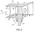
- FIG. 2 is a schematic view of a portion of turbine 16 of gas turbine engine 10 shown in FIG. 1 .
- turbine 16 includes a hot gas path component such as a turbine blade 26 and a stator vane 28.
- An airfoil 30 used with stator vane 28 includes a leading edge 32 that is directly exposed to hot gas flow 22.
- Stator vanes 28 may be cooled by air routed from one or more stages of compressor 12 through a casing 34 of gas turbine engine 10.
- An airfoil 36 used with hot gas path component 26 includes a leading edge 38 that is directly exposed to hot gas flow 22, and an axially opposite trailing edge 40.
- Hot gas path component 26 may also be cooled by pressurized air 24 routed from one or more stages of compressor 12 through casing 34 of gas turbine engine 10.
- pressurized air 24 is described as the cooling fluid used to cool the components exposed to hot gas flow 22, e.g., stator vane 28 and hot gas path component 26.
- a fluid other than pressurized air 24 may be used to cool components exposed to hot gas flow 22.
- the term "fluid" as used herein includes any medium or material that flows, including, but not limited to gas, steam, and air.
- at least one cooling system 42 defined in hot gas path component 26 is coupled in flow communication with a cooling fluid supply conduit 44.
- cooling fluid supply conduit 44 is connected to compressor 12.
- gas turbine engine 10 ingests air into compressor 12.
- Compressor 12 rotating at a high rotational speed compresses or pressurizes the air and channels a portion of pressurized air 24 to combustor 14 and a portion of pressurized air 24 to other areas of gas turbine engine 10 for use in cooling components exposed to heat generated by gas turbine engine 10.
- Pressurized air 24 is mixed with fuel in combustor 14 and ignited to generate hot gas flow 22.
- Hot gas flow 22 is channeled from combustor 14 toward turbine 16 where hot gas flow 22 passes over stator vane 28 and impacts hot gas path component 26 connected to a rotor wheel 46.
- Rotor wheel 46 is rotated by hot gas flow 22 impacting hot gas path component 26.
- Hot gas flow 22 also transfers heat to stator vane 28 and hot gas path component 26.
- a portion of pressurized air 24 is channeled through cooling system 42 formed in at least hot gas path component 26 to facilitate cooling the component.
- FIG. 3 is a partial isometric sectional view of gas turbine engine 10 illustrating an exemplary rotor wheel assembly 48 and includes two hot gas path components 26 coupled to rotor wheel 46.
- hot gas path component 26 is coupled within turbine 16.
- Gas turbine engine 10 includes a plurality of hot gas path components 26. While a turbine blade is described herein, a hot gas path component is any component of gas turbine engine 10 that is at least partially exposed to hot gas flow 22 through gas turbine engine 10, e.g., where the hot gas flow 22 operating temperature, in one example, is above 2500 degrees Fahrenheit (°F) ( ⁇ 1371 degrees Celsius (°C)).
- hot gas path component 26 includes, without limitation, bucket assemblies (also known as blades or blade assemblies), nozzle assemblies (also known as vanes or vane assemblies), shroud assemblies, transition pieces, retaining rings, and compressor exhaust components.
- Hot gas path component 26 is not limited to the examples described above, but is any component that is at least partially exposed to hot gas flow 22.
- hot gas path component 26 is not limited to components of gas turbine engine 10, but may be any type of component that is exposed to high temperature flows.
- airfoil 36 is at least partially hollow and is integrally coupled to a dovetail 50 at a platform 52.
- Platform 52 defines a portion of a radially inner boundary for hot gas flow 22 within gas turbine engine 10.
- Airfoil 36 generally includes a concave pressure side 54 extending between leading edge 38 and trailing edge 40, and an opposite, convex, suction side 56.
- Dovetail 50 includes an upper and lower pair of laterally or circumferentially opposite dovetail tangs 58 that are configured in a typical fir tree arrangement. Dovetail tangs 58 support hot gas path component 26 in a dovetail slot 60 formed in the perimeter of rotor wheel 46.
- Hot gas path components 26 can be securely coupled to rotor wheel 46 as a dovetail 50 of a respective hot gas path component 26 is inserted into a respective dovetail slot 60.
- hot gas path components 26 When assembled, hot gas path components 26 form an array of blades that extend circumferentially about the outer periphery of rotor wheel 46.
- each dovetail slot 60 is defined between each pair of circumferentially-spaced rotor wheel posts 62.
- Dovetail slot 60 includes slot tangs 64 that mate complementarily with turbine blade tangs 58 to provide pressure contact surfaces, through which at least centrifugal loads of hot gas path components 26 are induced into rotor wheel 46.
- dovetail 50 includes an integral root portion 66 that extends circumferentially between lower dovetail tangs 58.
- Root portion 66 is an integral extension of lower dovetail tangs 58 and is radially inward of and below tangs 58.
- Hot gas path component 26 may be fabricated integrally, for example, by casting of a suitable superalloy capable of withstanding the temperatures and stresses generated within turbine 16.
- root portion 66 includes a notch 68 defined adjacent to a forward end wall 70 of dovetail 50.
- root portion 66 may extend from forward end wall 70 to an opposite aft end wall 72, may include a lip (not shown) that extends radially inward at forward end wall 70, or may be formed in any shape that enables gas turbine engine 10 to operate as described herein. In the exemplary embodiment, root portion 66 facilitates enhancing the structural integrity and strength of dovetail 50.
- airfoil 36 is a least partially hollow and includes internal cooling system 42.
- Dovetail 50 includes a plurality of axially-aligned inlet apertures 74 that extend longitudinally through dovetail 50 and that are coupled in flow communication with cooling system 42 formed in airfoil 36. Pressurized air 24 bled from compressor 12 is channeled through dovetail slots 60 and into inlet apertures 74 to provide air 24 through dovetail 50 and into airfoil 36.
- FIG. 4 is a schematic cross-section of hot gas path component 26 (shown in FIG. 3 ) for use in gas turbine engine 10 (shown in FIG. 1 ) and including cooling system 42 formed therein.
- hot gas path component 26 When hot gas path component 26 is exposed to a hot gas flow 22, hot gas path component 26 is heated by hot gas flow 22 and can reach a temperature at which hot gas path component 26 may rapidly deteriorate.
- Cooling system 42 for hot gas path component 26 enables gas turbine engine 10 to function with hot gas flow 22 at an increased temperature, which increases the efficiency and performance of gas turbine engine 10.
- cooling system 42 includes a series of small passages, or micro-channels 76, formed in a substrate 78.
- "small" or “micro” channel dimensions range between approximately 0.010 inches (in.)(0.25 millimeters (mm)) and approximately 0.100 in. (2.54 mm).
- Substrate 78 includes an outer surface 80 and an inner surface 82.
- Micro-channels 76 are formed in outer surface 80 of substrate 78.
- Hot gas path component 26 includes a coating 84 that may include one or more material layers.
- coating 84 is a thermal barrier coating (TBC).
- hot gas path component 26 can be formed from a high temperature ceramic matrix composite (CMC) and include an environmental barrier coating (EBC) system that includes one or more layers.
- CMC thermal barrier coating
- EBC environmental barrier coating
- hot gas path component 26 also includes one or more covers or braze sheets 86 covering at least a portion of micro-channels 76.
- hot gas path component 26 is free of braze sheets 86, and micro-channels 76 are formed within hot gas path component 26 or in a surface of hot gas path component 26 to enable coating 84 to cover micro-channels 76 without blocking flow through the micro-channels.
- pressurized air 24 (not shown in FIG. 4 ) is provided to micro-channels 76 from at least one plenum 88, and pressurized air 24 flows through micro-channels 76 to cool coating 84.
- cooling system 42 utilizes backside convection cooling to supply pressurized air 24 to micro-channels 76, enabling pressurized air 24 to flow through micro-channels 76 to cool coating 84 at an increased heat transfer rate and with a relatively uniform temperature profile.
- Substrate 78 is typically cast prior to forming micro-channels 76 in outer surface 80 of substrate 78. Alternatively, micro-channels 76 could be cast in substrate 78 during fabrication.
- Substrate 78 is formed from any suitable material depending on the intended application for hot gas path component 26, for example, without limitation, Ni-base, Co-base, and Fe-base superalloys and the like. Some Ni-base superalloys are known to be advantageous because of a combination of desirable properties including high temperature strength and high temperature creep resistance.
- the material used to form substrate 78 may also include a NiAl intermetallic alloy, as these alloys are also known to possess a combination of superior properties including high temperature strength and high temperature creep resistance that are advantageous for use in turbine engine applications used for aircraft.
- substrate 78 is formed from any material that enables substrate 78 to function as described herein.
- braze sheets 86 conform to the profile of outer surface 80 and cover micro-channels 76, thereby forming cooling passages 90.
- Coating 84 extends along at least a portion of outer surface 80 and braze sheets 86 of substrate 78, forming a protective material layer on hot gas path component 26.
- coating 84 includes one or more material layers, such as a bondcoat and a TBC.
- coating 84 may be yttria-stabilized zirconia and may be applied to hot gas path component 26 through a physical vapor deposition process or thermal spray process as described herein.
- coating 84 may be a ceramic, for example, without limitation, a thin layer of zirconia modified by other refractory oxides such as oxides formed from Group IV, V and VI elements or oxides modified by Lanthanide series elements such as La, Nd, Gd, Yb, and the like.
- coating 84 has a thickness in the range of 0.1 to 2.0 millimeters, and more particularly, in the range of 0.1 to 1 millimeter, and still more particularly 0.1 to 0.5 millimeters for industrial gas turbine components.
- other thicknesses may be utilized depending on the requirements for a particular hot gas path component 26.
- coating 84 is disposed over at least a portion of outer surface 80 of substrate 78 by performing an ion plasma deposition.
- ion plasma deposition includes placing a cathode formed of a coating material into a vacuum environment within a vacuum chamber, providing substrate 78 within the vacuum environment, supplying a current to the cathode to form a cathodic arc upon a cathode surface resulting in erosion or evaporation of coating material from the cathode surface, and depositing the coating material from the cathode upon the substrate outer surface 80.
- the ion plasma deposition process includes a plasma vapor deposition process.
- Non-limiting examples of coating 84 include structural coatings, bond coatings, oxidation-resistant coatings, and thermal barrier coatings.
- coating 84 is disposed over at least a portion of outer surface 80 of substrate 78 by performing a thermal spray process.
- the thermal spray process includes combustion spraying and/or plasma spraying.
- the combustion spraying process includes high velocity oxygen fuel spraying (HVOF) or high velocity air fuel spraying (HVAF).
- the plasma spraying process includes atmospheric (such as air or inert gas) plasma spray or low pressure plasma spray (LPPS), which is also known as vacuum plasma spray (VPS).
- techniques for depositing one or more layers of coating 84 include, without limitation, sputtering, electron beam physical vapor deposition, electroless plating, electroplating, and any other process that enables coating 84 to function as described herein.
- FIG. 5 is a schematic perspective view of a portion of hot gas path component 26 shown in FIG. 4 illustrating three micro-channels 76 that extend partially along outer surface 80 of substrate 78 and channel cooling fluid to respective film cooling holes 92.
- FIG. 6 is a schematic cross-section of one of micro-channels 76 shown in FIG. 5 , illustrating micro-channel 76 channeling pressurized air 24 from a plenum access passage 94 to one or more film cooling holes 92.
- micro-channels 76 channel pressurized air 24 from a respective plenum access passage 94 to a respective exiting film cooling hole 92 or exhaust passage.
- micro-channels 76 are spaced apart along a length of micro-channel 76 thus forming a trench exit micro-channel.
- micro-channels 76 extend along outer surface 80 of substrate 78 and exit off an edge of hot gas path component 26, such as a trailing edge or a bucket tip, or an end wall edge 104 (shown in FIG. 3 ).
- film cooling holes 92 are shown in FIG. 5 as being round, this is simply a non-limiting example. Film cooling holes 92 may be any shaped hole that enables film cooling holes 92 to function as described herein.
- micro-channel 76 is formed in outer surface 80 of substrate 78.
- Plenum access passage 94 extends through substrate 78 from outer surface 80 to inner surface 82 and is formed at an acute angle to micro-channel 76.
- micro-channel 76 is shown as a horizontal and substantially linear channel that is substantially parallel to the edge outer surface 80.
- Plenum access passage 94 is formed at an angle ⁇ with respect to micro-channel 76 such that angle ⁇ is less than 90°.
- Plenum access passage 94 does not intersect micro-channel 76, but rather is connected in fluid communication to micro-channel 76 by a metering passage 96.
- plenum access passage 94 is formed at an acute angle to metering passage 96.
- metering passage 96 is shown as a substantially linear channel that extends between and fluidly couples plenum access passage 94 to micro-channel 76.
- Plenum access passage 94 is formed at an angle ⁇ with respect to metering passage 96 such that angle ⁇ is less than 90°.
- micro-channel 76, plenum access passage 94, and metering passage 96 may be formed using a variety of techniques.
- techniques for forming these features include laser machining, water jet machining, electro-chemical machining (ECM), electro-discharge machining (EDM), photolithography, or any other process capable of providing channels with proper sizes and tolerances.
- water jet machining is used and utilizes a high-velocity stream of abrasive particles (e.g., abrasive "grit”) suspended in a stream of high pressure water. The pressure of the water varies considerably, but is often in the range of about 35-620 MPa.
- a number of abrasive materials can be used, such as garnet, aluminum oxide, silicon carbide, and glass beads.
- the capability of abrasive liquid jet machining techniques facilitates the removal of material in stages to varying depths, with control of the channel shape. For example, without limitation, this process enables plenum access passage 94 and metering passage 96 feeding micro-channel 76 to be drilled either as a straight hole of constant cross section, a shaped hole (elliptical etc.), or a converging or diverging hole.
- the abrasive liquid jet system can include a multi-axis computer numerically controlled (CNC) unit. CNC units enable movement of the cutting tool along a number of axes, including X, Y, and Z axes, as well as rotational axes.
- CNC computer numerically controlled
- micro-channel 76 channels pressurized air 24 from plenum access passage 94 to exiting film cooling hole 92.
- a length of micro-channel 76 is in the range of 10 to 1000 times a diameter of film cooling hole 92, and more particularly, in the range of 20 to 100 times film cooling hole 92 diameter.
- Micro-channels 76 can be used anywhere on outer surface 80 of hot gas path component 26.
- micro-channels 76 can have any configuration, for example, straight, curved, or have multiple curves.
- Micro-channels 76 have a depth A and a width (not shown) in the range between approximately 0.010 inches (in.) (0.25 millimeters (mm)) and approximately 0.100 in. (2.54 mm).
- micro-channels 76 can have any depth and width that enables micro-channels 76 to function as described herein.
- micro-channels 76 are semicircular and depth A is representative of a radius dimension.
- micro-channels 76 can have any cross-sectional shape that enables micro-channels 76 to function as described herein, for example, without limitation, square, rectangular, triangular, and semioval shapes. It is contemplated that various micro-channels 76 have cross-sections with a certain geometric shape, while other micro-channels 76 have cross-sections with another geometric shape.
- micro-channel 76 can be generally straight, or can be generally curved, sinusoidal, or serpentine. Micro-channel 76 can be oriented such that pressurized air 24 flows through micro-channel 76 in any direction with respect to hot gas flow 22. For example, without limitation, pressurized air 24 can flow through micro-channel 76 or any portion thereof in a generally downstream direction with respect to hot gas flow 22, or in a generally upstream direction with respect to hot gas flow 22, or in any other direction with respect to the hot gas flow 22. In some embodiments, micro-channel 76 may be a singular, discrete micro-channel. In other embodiments, micro-channel 76, or any portion of micro-channel 76, may branch off from micro-channel 76 to form multiple micro-channel branches.
- micro-channel 76 in some embodiments, wraps around the entire perimeter of hot gas path component 26, or wraps around only portions of the perimeter of hot gas path component 26. However, it is understood that each of micro-channels 76 generally do not intersect with any other micro-channel 76.
- metering passage 96 extends in fluid communication between an end of micro-channel 76 opposite film cooling hole 92 and plenum access passage 94. As shown in FIG. 6 , metering passage 96 intersects plenum access passage 94 at a distance D below outer surface 80 of substrate 78. This facilitates defining a particle collection chamber 98.
- collection chamber 98 is shown between braze sheet 86 and the intersection of metering passage 96. Alternatively, collection chamber 98 is formed between coating 84 or outer surface 80 and the intersection of metering passage 96.
- collection chamber 98 includes an exit passage 106 to allow built up particulate 100 to be removed from collection chamber 98.
- exit passage 106 is smaller in cross-sectional area than micro-channel 76; however, exit passage 106 is any size that enables cooling system 42 to function as described herein.
- metering passage 96 has a cross-sectional width B in the range between approximately 0.025 inches (in.) (0.6 millimeters (mm)) and approximately 0.035 in. (0.9 mm).
- metering passage 96 is circular and width B is representative of a diameter dimension.
- metering passage 96 can have any cross-sectional shape that enables metering passage 96 to function as described herein, for example, without limitation, square, rectangular, triangular, and semioval shapes. It is contemplated that various metering passages 96 have cross-sections with a certain geometric shape, while other metering passages 96 have cross-sections with another geometric shape.
- plenum access passage 94 has a cross-sectional width C, which is larger than cross-sectional width B of metering passage 96.
- width C is in the range between approximately 0.040 inches (in.) (1.0 millimeters (mm)) and approximately 0.060 in. (1.5 mm).
- plenum access passage 94 is circular and width C is representative of a diameter dimension.
- a ratio of the diameter of plenum access passage 94 to a diameter of metering hole passage 96 is between about 1.14 and about 2.4.
- plenum access passage 94 can have any cross-sectional shape that enables plenum access passage 94 to function as described herein, for example, without limitation, square, rectangular, triangular, and semioval shapes. It is contemplated that various plenum access passages 94 have cross-sections with a certain geometric shape, while other plenum access passages 94 have cross-sections with another geometric shape.
- plenum access passage 94 includes particle collection chamber 98.
- particle collection chamber 98 functions to mitigate the potential for micro-channel 76 and film cooling hole 92 blockage.
- Particulate 100 that is mixed with pressurized air 24 poses a risk of film cooling hole 92 and micro-channel 76 blockage.
- Such blockage reduces flow through micro-channel 76 or completely obstructs micro-channel 76, thus reducing cooling capability and raising the temperature of hot gas path component 26 above its design limit.
- Particle collection chamber 98 provides a means of reducing the amount of particulate 100 passing through metering passage 96 in cooling system 42 by modifying the flow path geometry.
- collection chamber 98 includes exit passage 106 to enable particulate 100 to be exhausted into hot gas flow 22.
- pressurized air 24 flows through cooling system 42, and in particular, plenum 88, at a pressure generally higher than a pressure in plenum access passage 94, metering passage 96, and micro-channel 76.
- the pressure differential causes a portion of pressurized air 24 contained within cooling system 42 to flow into and through plenum access passage 94, and from plenum access passage 94 into and through metering passage 96 and micro-channel 76. Because plenum access passage 94 is formed at an acute angle with respect to metering passage 96 and micro-channel 76, pressurized air 24 and any particulate 100 will flow into particle collection chamber 98.
- the inertia of particulate 100 carries the particulate into particle collection chamber 98 where it is collected and prevented from entering the smaller cross-sectional area metering passage 96 as pressurized air 24 makes a sharp turn into metering passage 96.
- collection chamber 98 includes exit passage 106 such that collected particulate 100 is exhausted into hot gas flow 22.
- plenum access passage 94 is configured to provide convection cooling to substrate 78 and coating 84.
- plenum access passage 94 is oriented generally at an angle that enables pressurized air 24 to impact on braze sheet 86, substrate 78, or coating 84, thus increasing the cooling effectiveness of pressurized air 24.
- pressurized air 24 flows through plenum access passage 94 and is provided to metering passage 96 and micro-channel 76, pressurized air 24 providing cooling of hot gas path component 26.
- pressurized air 24 may be exhausted from micro-channels 76.
- pressurized air 24 may be exhausted adjacent an outer surface 102 of coating 84.
- pressurized air 24 may be exhausted off an edge of hot gas path component 26, such as trailing edge 40 or leading edge 38 of airfoil 36, or end wall edge 104 (shown in FIG. 3 ) of hot gas path component 26 into the path of hot gas flow 22.
- the systems and methods described herein facilitate cooling of a hot gas path component 26 at a high heat transfer rate and with a relatively uniform temperature profile.
- the cooling system 42 of the present disclosure may increase the life of hot gas path component 26 and enable hot gas path component 26 to be utilized with higher temperature hot gas flows 22, thus increasing the performance and efficiency of gas turbine engine 10.
Abstract
Description
- The field of the present disclosure relates generally to turbine engines, and more particularly to systems for cooling hot gas path components in turbine engines.
- Gas turbine systems are widely utilized in fields such as power generation. A conventional gas turbine system includes a compressor, a combustor, and a turbine. During operation of the gas turbine system, various components in the system are subjected to high temperature flows, which can cause the components to fail. Since higher temperature flows generally result in increased performance, efficiency, and power output of the gas turbine system and are thus desired in a gas turbine system, the components that are subjected to high temperature flows must be cooled to allow the gas turbine system to operate with flows at increased temperatures.
- Various strategies are known in the art for cooling components that are subjected to high temperature flows. These components are typically known as hot gas path components. For example, a series of internal cooling passages may be formed in a hot gas path component. A cooling fluid may be provided to the passages from a plenum, and the cooling fluid may flow through the passages, cooling the hot gas path component substrate and coatings. However, the cooling fluid can be contaminated with various types of particles, which can cause blockage of the internal cooling passages, or serpentines formed in the hot gas path component that is cooled with the cooling fluid. Such blockage can shorten the life of these components.
- In one aspect, a cooling system for a hot gas path component is provided. The cooling system includes a substrate comprising an outer surface and an inner surface. The inner surface defines at least one interior space. The cooling system includes a passage extending between the outer surface and the inner surface of the substrate. Moreover, the cooling system includes an access passage formed in the substrate and extending from the outer surface to the at least one inner space. The access passage is formed at a first acute angle to the passage. In addition, the access passage includes a particle collection chamber. The access passage is configured to channel a cooling fluid to the passage. Furthermore, the passage is configured to channel the cooling fluid therethrough to cool the substrate.
- In another aspect, a gas turbine engine is provided. The gas turbine engine includes a compressor, a turbine coupled to the compressor, and a hot gas path component disposed in a least one of the compressor and the turbine. The hot gas path component includes a substrate comprising an outer surface and an inner surface. The inner surface defines at least one interior space. The hot gas path component also includes a passage extending between the outer surface and the inner surface of the substrate. Moreover, the hot gas path component includes an access passage formed in the substrate and extending from the outer surface to the at least one inner space. The access passage is formed at a first acute angle to the passage. The access passage includes a particle collection chamber. The access passage is configured to channel a cooling fluid to the passage. The passage is configured to channel the cooling fluid therethrough to cool the substrate.
- These and other features, aspects, and advantages of the present disclosure will become better understood when the following detailed description is read with reference to the accompanying drawings in which like characters represent like parts throughout the drawings, wherein:
-
FIG. 1 is a schematic view of an exemplary gas turbine engine; -
FIG. 2 is a schematic view of a portion of a turbine of the gas turbine engine shown inFIG. 1 ; -
FIG. 3 is a partial isometric sectional view of the gas turbine engine shown inFIG. 1 , illustrating a rotor wheel assembly including two hot gas path components coupled to a rotor wheel; -
FIG. 4 is a schematic cross-section of the hot gas path component shown inFIG. 3 for use in gas turbine engine ofFIG. 1 and including a cooling system formed therein; -
FIG. 5 is a schematic perspective view of a portion of the hot gas path component shown inFIG. 4 illustrating three micro-channels that extend partially along an outer surface of a substrate to channel cooling fluid to respective film cooling holes; and -
FIG. 6 is a schematic cross-section of one of the micro-channels shown inFIG. 5 , illustrating the micro-channel channeling pressurized air from a plenum access passage to a film cooling hole. - Unless otherwise indicated, the drawings provided herein are meant to illustrate features of embodiments of the disclosure. These features are believed to be applicable in a wide variety of systems comprising one or more embodiments of the disclosure. As such, the drawings are not meant to include all conventional features known by those of ordinary skill in the art to be required for the practice of the embodiments disclosed herein.
- In the following specification and the claims, reference will be made to a number of terms, which shall be defined to have the following meanings. The singular forms "a", "an", and "the" include plural references unless the context clearly dictates otherwise. Approximating language, as used herein throughout the specification and claims, may be applied to modify any quantitative representation that could permissibly vary without resulting in a change in the basic function to which it is related. Accordingly, a value modified by a term or terms, such as "about" and "substantially", are not to be limited to the precise value specified. In at least some instances, the approximating language may correspond to the precision of an instrument for measuring the value. Here and throughout the specification and claims, range limitations may be combined and/or interchanged; such ranges are identified and include all the sub-ranges contained therein unless context or language indicates otherwise.
- Approximating language, as used herein throughout the specification and claims, may be applied to modify any quantitative representation that could permissibly vary without resulting in a change in the basic function to which it is related. Accordingly, a value modified by a term or terms, such as "about", "approximately", and "substantially", are not to be limited to the precise value specified. In at least some instances, the approximating language may correspond to the precision of an instrument for measuring the value. Here and throughout the specification and claims, range limitations may be combined and/or interchanged; such ranges are identified and include all the sub-ranges contained therein unless context or language indicates otherwise.
-
FIG. 1 is a schematic view of a rotary machine, i.e., a turbomachine, and more specifically, a turbine engine. In the exemplary embodiment, the turbine engine is agas turbine engine 10. Alternatively, the rotary machine is any other turbine engine and/or rotary machine, including, without limitation, a steam turbine engine, a centrifugal compressor, and a turbocharger. In the exemplary embodiment,gas turbine engine 10 includes at least one of each of acompressor 12, acombustor 14, aturbine 16, and afuel nozzle 20.Fuel nozzle 20 is configured to inject and mix fuel (not shown) with pressurizedair 24 incombustor 14.Combustor 14 ignites and combusts the fuel-air mixture (not shown) and then passes ahot gas flow 22 intoturbine 16.Turbine 16 includes one or more stators having fixed vanes or blades (not shown inFIG. 1 ), and one or more rotors having blades or buckets (not shown inFIG. 1 ) that rotate relative to the stators.Hot gas flow 22 passes over the turbine rotor blades, thereby driving the turbine rotor to rotate.Turbine 16 is coupled to a singlerotatable shaft 18 such that it rotates the shaft ashot gas flow 22 passes over the turbine blades. In alternative embodiments,rotatable shaft 18 is a plurality of shaft segments coupled together to formrotatable shaft 18. In the exemplary embodiment,rotatable shaft 18 is coupled tocompressor 12.Compressor 12 includes blades (not shown) rigidly mounted to a rotor (not shown) that is driven to rotate byrotatable shaft 18. As air passes over the rotating blades, air pressure increases, thereby providingcombustor 14 with sufficientpressurized air 24 for proper combustion. -
FIG. 2 is a schematic view of a portion ofturbine 16 ofgas turbine engine 10 shown inFIG. 1 . In the exemplary embodiment,turbine 16 includes a hot gas path component such as aturbine blade 26 and astator vane 28. Anairfoil 30 used withstator vane 28 includes aleading edge 32 that is directly exposed tohot gas flow 22.Stator vanes 28 may be cooled by air routed from one or more stages ofcompressor 12 through acasing 34 ofgas turbine engine 10. Anairfoil 36 used with hotgas path component 26 includes aleading edge 38 that is directly exposed tohot gas flow 22, and an axially opposite trailingedge 40. Hotgas path component 26 may also be cooled bypressurized air 24 routed from one or more stages ofcompressor 12 throughcasing 34 ofgas turbine engine 10. - In the exemplary embodiment,
pressurized air 24 is described as the cooling fluid used to cool the components exposed tohot gas flow 22, e.g.,stator vane 28 and hotgas path component 26. In alternative embodiments, a fluid other thanpressurized air 24 may be used to cool components exposed tohot gas flow 22. It should also be appreciated that the term "fluid" as used herein includes any medium or material that flows, including, but not limited to gas, steam, and air. In the exemplary embodiment, at least onecooling system 42 defined in hotgas path component 26 is coupled in flow communication with a coolingfluid supply conduit 44. In the exemplary embodiment, coolingfluid supply conduit 44 is connected tocompressor 12. - In operation,
gas turbine engine 10 ingests air intocompressor 12.Compressor 12, rotating at a high rotational speed compresses or pressurizes the air and channels a portion ofpressurized air 24 tocombustor 14 and a portion ofpressurized air 24 to other areas ofgas turbine engine 10 for use in cooling components exposed to heat generated bygas turbine engine 10.Pressurized air 24 is mixed with fuel incombustor 14 and ignited to generatehot gas flow 22.Hot gas flow 22 is channeled fromcombustor 14 towardturbine 16 wherehot gas flow 22 passes overstator vane 28 and impacts hotgas path component 26 connected to arotor wheel 46.Rotor wheel 46 is rotated byhot gas flow 22 impacting hotgas path component 26.Hot gas flow 22 also transfers heat tostator vane 28 and hotgas path component 26. A portion ofpressurized air 24 is channeled throughcooling system 42 formed in at least hotgas path component 26 to facilitate cooling the component. -
FIG. 3 is a partial isometric sectional view ofgas turbine engine 10 illustrating an exemplaryrotor wheel assembly 48 and includes two hotgas path components 26 coupled torotor wheel 46. In the exemplary embodiment, hotgas path component 26 is coupled withinturbine 16.Gas turbine engine 10 includes a plurality of hotgas path components 26. While a turbine blade is described herein, a hot gas path component is any component ofgas turbine engine 10 that is at least partially exposed tohot gas flow 22 throughgas turbine engine 10, e.g., where thehot gas flow 22 operating temperature, in one example, is above 2500 degrees Fahrenheit (°F) (∼1371 degrees Celsius (°C)). For example, hotgas path component 26 includes, without limitation, bucket assemblies (also known as blades or blade assemblies), nozzle assemblies (also known as vanes or vane assemblies), shroud assemblies, transition pieces, retaining rings, and compressor exhaust components. Hotgas path component 26 is not limited to the examples described above, but is any component that is at least partially exposed tohot gas flow 22. In addition, hotgas path component 26 is not limited to components ofgas turbine engine 10, but may be any type of component that is exposed to high temperature flows. - In the exemplary embodiment,
airfoil 36 is at least partially hollow and is integrally coupled to adovetail 50 at aplatform 52.Platform 52 defines a portion of a radially inner boundary forhot gas flow 22 withingas turbine engine 10.Airfoil 36 generally includes aconcave pressure side 54 extending between leadingedge 38 and trailingedge 40, and an opposite, convex,suction side 56.Dovetail 50 includes an upper and lower pair of laterally or circumferentiallyopposite dovetail tangs 58 that are configured in a typical fir tree arrangement. Dovetail tangs 58 support hotgas path component 26 in adovetail slot 60 formed in the perimeter ofrotor wheel 46. Hotgas path components 26 can be securely coupled torotor wheel 46 as adovetail 50 of a respective hotgas path component 26 is inserted into arespective dovetail slot 60. When assembled, hotgas path components 26 form an array of blades that extend circumferentially about the outer periphery ofrotor wheel 46. In the exemplary embodiment, eachdovetail slot 60 is defined between each pair of circumferentially-spaced rotor wheel posts 62.Dovetail slot 60 includes slot tangs 64 that mate complementarily with turbine blade tangs 58 to provide pressure contact surfaces, through which at least centrifugal loads of hotgas path components 26 are induced intorotor wheel 46. - In the exemplary embodiment,
dovetail 50 includes anintegral root portion 66 that extends circumferentially between lower dovetail tangs 58.Root portion 66 is an integral extension oflower dovetail tangs 58 and is radially inward of and below tangs 58. Hotgas path component 26 may be fabricated integrally, for example, by casting of a suitable superalloy capable of withstanding the temperatures and stresses generated withinturbine 16. In the exemplary embodiment,root portion 66 includes anotch 68 defined adjacent to aforward end wall 70 ofdovetail 50. Alternatively,root portion 66 may extend fromforward end wall 70 to an oppositeaft end wall 72, may include a lip (not shown) that extends radially inward atforward end wall 70, or may be formed in any shape that enablesgas turbine engine 10 to operate as described herein. In the exemplary embodiment,root portion 66 facilitates enhancing the structural integrity and strength ofdovetail 50. - In the exemplary embodiment,
airfoil 36 is a least partially hollow and includesinternal cooling system 42.Dovetail 50 includes a plurality of axially-alignedinlet apertures 74 that extend longitudinally throughdovetail 50 and that are coupled in flow communication withcooling system 42 formed inairfoil 36.Pressurized air 24 bled fromcompressor 12 is channeled throughdovetail slots 60 and intoinlet apertures 74 to provideair 24 throughdovetail 50 and intoairfoil 36. -
FIG. 4 is a schematic cross-section of hot gas path component 26 (shown inFIG. 3 ) for use in gas turbine engine 10 (shown inFIG. 1 ) and including coolingsystem 42 formed therein. When hotgas path component 26 is exposed to ahot gas flow 22, hotgas path component 26 is heated byhot gas flow 22 and can reach a temperature at which hotgas path component 26 may rapidly deteriorate.Cooling system 42 for hotgas path component 26 enablesgas turbine engine 10 to function withhot gas flow 22 at an increased temperature, which increases the efficiency and performance ofgas turbine engine 10. - In the exemplary embodiment, cooling
system 42 includes a series of small passages, or micro-channels 76, formed in asubstrate 78. As used herein, "small" or "micro" channel dimensions range between approximately 0.010 inches (in.)(0.25 millimeters (mm)) and approximately 0.100 in. (2.54 mm).Substrate 78 includes anouter surface 80 and aninner surface 82. Micro-channels 76 are formed inouter surface 80 ofsubstrate 78. Hotgas path component 26 includes acoating 84 that may include one or more material layers. In the exemplary embodiment, coating 84 is a thermal barrier coating (TBC). In alternative embodiments, hotgas path component 26 can be formed from a high temperature ceramic matrix composite (CMC) and include an environmental barrier coating (EBC) system that includes one or more layers. - In the exemplary embodiment, hot
gas path component 26 also includes one or more covers or brazesheets 86 covering at least a portion ofmicro-channels 76. Alternatively, hotgas path component 26 is free ofbraze sheets 86, and micro-channels 76 are formed within hotgas path component 26 or in a surface of hotgas path component 26 to enablecoating 84 to cover micro-channels 76 without blocking flow through the micro-channels. In the exemplary embodiment, pressurized air 24 (not shown inFIG. 4 ) is provided to micro-channels 76 from at least oneplenum 88, andpressurized air 24 flows throughmicro-channels 76 to coolcoating 84. In the exemplary embodiment, coolingsystem 42 utilizes backside convection cooling to supplypressurized air 24 to micro-channels 76, enablingpressurized air 24 to flow throughmicro-channels 76 to cool coating 84 at an increased heat transfer rate and with a relatively uniform temperature profile. -
Substrate 78 is typically cast prior to formingmicro-channels 76 inouter surface 80 ofsubstrate 78. Alternatively, micro-channels 76 could be cast insubstrate 78 during fabrication.Substrate 78 is formed from any suitable material depending on the intended application for hotgas path component 26, for example, without limitation, Ni-base, Co-base, and Fe-base superalloys and the like. Some Ni-base superalloys are known to be advantageous because of a combination of desirable properties including high temperature strength and high temperature creep resistance. The material used to formsubstrate 78 may also include a NiAl intermetallic alloy, as these alloys are also known to possess a combination of superior properties including high temperature strength and high temperature creep resistance that are advantageous for use in turbine engine applications used for aircraft. In alternative embodiments,substrate 78 is formed from any material that enablessubstrate 78 to function as described herein. - In the exemplary embodiment, braze
sheets 86 conform to the profile ofouter surface 80 and cover micro-channels 76, thereby formingcooling passages 90.Coating 84 extends along at least a portion ofouter surface 80 and brazesheets 86 ofsubstrate 78, forming a protective material layer on hotgas path component 26. In one embodiment, coating 84 includes one or more material layers, such as a bondcoat and a TBC. For example, coating 84 may be yttria-stabilized zirconia and may be applied to hotgas path component 26 through a physical vapor deposition process or thermal spray process as described herein. Alternatively, coating 84 may be a ceramic, for example, without limitation, a thin layer of zirconia modified by other refractory oxides such as oxides formed from Group IV, V and VI elements or oxides modified by Lanthanide series elements such as La, Nd, Gd, Yb, and the like. For particular configurations, coating 84 has a thickness in the range of 0.1 to 2.0 millimeters, and more particularly, in the range of 0.1 to 1 millimeter, and still more particularly 0.1 to 0.5 millimeters for industrial gas turbine components. However, other thicknesses may be utilized depending on the requirements for a particular hotgas path component 26. -
Coating 84 in deposited onto hotgas path component 26 using a variety of techniques. In one embodiment, coating 84 is disposed over at least a portion ofouter surface 80 ofsubstrate 78 by performing an ion plasma deposition. Briefly, ion plasma deposition includes placing a cathode formed of a coating material into a vacuum environment within a vacuum chamber, providingsubstrate 78 within the vacuum environment, supplying a current to the cathode to form a cathodic arc upon a cathode surface resulting in erosion or evaporation of coating material from the cathode surface, and depositing the coating material from the cathode upon the substrateouter surface 80. In one embodiment, the ion plasma deposition process includes a plasma vapor deposition process. Non-limiting examples ofcoating 84 include structural coatings, bond coatings, oxidation-resistant coatings, and thermal barrier coatings. In alternative embodiments, coating 84 is disposed over at least a portion ofouter surface 80 ofsubstrate 78 by performing a thermal spray process. For example, without limitation, the thermal spray process includes combustion spraying and/or plasma spraying. The combustion spraying process includes high velocity oxygen fuel spraying (HVOF) or high velocity air fuel spraying (HVAF). The plasma spraying process includes atmospheric (such as air or inert gas) plasma spray or low pressure plasma spray (LPPS), which is also known as vacuum plasma spray (VPS). Alternatively, techniques for depositing one or more layers ofcoating 84 include, without limitation, sputtering, electron beam physical vapor deposition, electroless plating, electroplating, and any other process that enables coating 84 to function as described herein. -
FIG. 5 is a schematic perspective view of a portion of hotgas path component 26 shown inFIG. 4 illustrating three micro-channels 76 that extend partially alongouter surface 80 ofsubstrate 78 and channel cooling fluid to respective film cooling holes 92.FIG. 6 is a schematic cross-section of one ofmicro-channels 76 shown inFIG. 5 , illustratingmicro-channel 76 channelingpressurized air 24 from aplenum access passage 94 to one or more film cooling holes 92. In the exemplary embodiment, micro-channels 76 channel pressurizedair 24 from a respectiveplenum access passage 94 to a respective exitingfilm cooling hole 92 or exhaust passage. Alternative embodiments, however, do not include film cooling holes 92. In one particular embodiment, as shown with respect to onemicro-channel 76 inFIG. 5 , more than one film cooling holes 92 is spaced apart along a length ofmicro-channel 76 thus forming a trench exit micro-channel. In embodiments without cooling holes 92, micro-channels 76 extend alongouter surface 80 ofsubstrate 78 and exit off an edge of hotgas path component 26, such as a trailing edge or a bucket tip, or an end wall edge 104 (shown inFIG. 3 ). In addition, it should be noted that although film cooling holes 92 are shown inFIG. 5 as being round, this is simply a non-limiting example. Film cooling holes 92 may be any shaped hole that enables film cooling holes 92 to function as described herein. - In the exemplary embodiment,
micro-channel 76 is formed inouter surface 80 ofsubstrate 78.Plenum access passage 94 extends throughsubstrate 78 fromouter surface 80 toinner surface 82 and is formed at an acute angle to micro-channel 76. For example, in the exemplary embodiment,micro-channel 76 is shown as a horizontal and substantially linear channel that is substantially parallel to the edgeouter surface 80.Plenum access passage 94 is formed at an angle α with respect to micro-channel 76 such that angle α is less than 90°.Plenum access passage 94 does not intersect micro-channel 76, but rather is connected in fluid communication to micro-channel 76 by ametering passage 96. Furthermore,plenum access passage 94 is formed at an acute angle tometering passage 96. For example, in the exemplary embodiment,metering passage 96 is shown as a substantially linear channel that extends between and fluidly couples plenumaccess passage 94 to micro-channel 76.Plenum access passage 94 is formed at an angle β with respect tometering passage 96 such that angle β is less than 90°. - In the exemplary embodiment,
micro-channel 76,plenum access passage 94, andmetering passage 96 may be formed using a variety of techniques. For example, without limitation, techniques for forming these features include laser machining, water jet machining, electro-chemical machining (ECM), electro-discharge machining (EDM), photolithography, or any other process capable of providing channels with proper sizes and tolerances. In one particular embodiment, water jet machining is used and utilizes a high-velocity stream of abrasive particles (e.g., abrasive "grit") suspended in a stream of high pressure water. The pressure of the water varies considerably, but is often in the range of about 35-620 MPa. A number of abrasive materials can be used, such as garnet, aluminum oxide, silicon carbide, and glass beads. The capability of abrasive liquid jet machining techniques facilitates the removal of material in stages to varying depths, with control of the channel shape. For example, without limitation, this process enablesplenum access passage 94 andmetering passage 96feeding micro-channel 76 to be drilled either as a straight hole of constant cross section, a shaped hole (elliptical etc.), or a converging or diverging hole. In addition, the abrasive liquid jet system can include a multi-axis computer numerically controlled (CNC) unit. CNC units enable movement of the cutting tool along a number of axes, including X, Y, and Z axes, as well as rotational axes. - In the exemplary embodiment, micro-channel 76 channels pressurized
air 24 fromplenum access passage 94 to exitingfilm cooling hole 92. Typically, a length ofmicro-channel 76 is in the range of 10 to 1000 times a diameter offilm cooling hole 92, and more particularly, in the range of 20 to 100 timesfilm cooling hole 92 diameter. Micro-channels 76 can be used anywhere onouter surface 80 of hotgas path component 26. In addition, micro-channels 76 can have any configuration, for example, straight, curved, or have multiple curves. - Micro-channels 76 have a depth A and a width (not shown) in the range between approximately 0.010 inches (in.) (0.25 millimeters (mm)) and approximately 0.100 in. (2.54 mm). Alternatively, micro-channels 76 can have any depth and width that enables micro-channels 76 to function as described herein. In the exemplary embodiment, micro-channels 76 are semicircular and depth A is representative of a radius dimension. In alternative embodiments, micro-channels 76 can have any cross-sectional shape that enables micro-channels 76 to function as described herein, for example, without limitation, square, rectangular, triangular, and semioval shapes. It is contemplated that
various micro-channels 76 have cross-sections with a certain geometric shape, while other micro-channels 76 have cross-sections with another geometric shape. - In the exemplary embodiment, micro-channel 76 can be generally straight, or can be generally curved, sinusoidal, or serpentine. Micro-channel 76 can be oriented such that
pressurized air 24 flows throughmicro-channel 76 in any direction with respect tohot gas flow 22. For example, without limitation,pressurized air 24 can flow throughmicro-channel 76 or any portion thereof in a generally downstream direction with respect tohot gas flow 22, or in a generally upstream direction with respect tohot gas flow 22, or in any other direction with respect to thehot gas flow 22. In some embodiments, micro-channel 76 may be a singular, discrete micro-channel. In other embodiments,micro-channel 76, or any portion ofmicro-channel 76, may branch off frommicro-channel 76 to form multiple micro-channel branches. It is contemplated thatmicro-channel 76, in some embodiments, wraps around the entire perimeter of hotgas path component 26, or wraps around only portions of the perimeter of hotgas path component 26. However, it is understood that each of micro-channels 76 generally do not intersect with anyother micro-channel 76. - In the exemplary embodiment,
metering passage 96 extends in fluid communication between an end ofmicro-channel 76 oppositefilm cooling hole 92 andplenum access passage 94. As shown inFIG. 6 ,metering passage 96 intersectsplenum access passage 94 at a distance D belowouter surface 80 ofsubstrate 78. This facilitates defining aparticle collection chamber 98. In the exemplary embodiment,collection chamber 98 is shown betweenbraze sheet 86 and the intersection ofmetering passage 96. Alternatively,collection chamber 98 is formed betweencoating 84 orouter surface 80 and the intersection ofmetering passage 96. In one embodiment,collection chamber 98 includes anexit passage 106 to allow built up particulate 100 to be removed fromcollection chamber 98. In general,exit passage 106 is smaller in cross-sectional area thanmicro-channel 76; however,exit passage 106 is any size that enables coolingsystem 42 to function as described herein. In the exemplary embodiment,metering passage 96 has a cross-sectional width B in the range between approximately 0.025 inches (in.) (0.6 millimeters (mm)) and approximately 0.035 in. (0.9 mm). In the exemplary embodiment,metering passage 96 is circular and width B is representative of a diameter dimension. In alternative embodiments,metering passage 96 can have any cross-sectional shape that enablesmetering passage 96 to function as described herein, for example, without limitation, square, rectangular, triangular, and semioval shapes. It is contemplated thatvarious metering passages 96 have cross-sections with a certain geometric shape, whileother metering passages 96 have cross-sections with another geometric shape. - In the exemplary embodiment,
plenum access passage 94 has a cross-sectional width C, which is larger than cross-sectional width B ofmetering passage 96. In particular, width C is in the range between approximately 0.040 inches (in.) (1.0 millimeters (mm)) and approximately 0.060 in. (1.5 mm). In the exemplary embodiment,plenum access passage 94 is circular and width C is representative of a diameter dimension. Thus, in the exemplary embodiment, a ratio of the diameter ofplenum access passage 94 to a diameter ofmetering hole passage 96 is between about 1.14 and about 2.4. In alternative embodiments,plenum access passage 94 can have any cross-sectional shape that enablesplenum access passage 94 to function as described herein, for example, without limitation, square, rectangular, triangular, and semioval shapes. It is contemplated that variousplenum access passages 94 have cross-sections with a certain geometric shape, while otherplenum access passages 94 have cross-sections with another geometric shape. - As described above,
plenum access passage 94 includesparticle collection chamber 98. In the exemplary embodiment,particle collection chamber 98 functions to mitigate the potential formicro-channel 76 andfilm cooling hole 92 blockage.Particulate 100 that is mixed withpressurized air 24 poses a risk offilm cooling hole 92 andmicro-channel 76 blockage. Such blockage reduces flow throughmicro-channel 76 or completely obstructs micro-channel 76, thus reducing cooling capability and raising the temperature of hotgas path component 26 above its design limit.Particle collection chamber 98 provides a means of reducing the amount ofparticulate 100 passing throughmetering passage 96 incooling system 42 by modifying the flow path geometry. In one embodiment,collection chamber 98 includesexit passage 106 to enable particulate 100 to be exhausted intohot gas flow 22. - In operation,
pressurized air 24 flows throughcooling system 42, and in particular,plenum 88, at a pressure generally higher than a pressure inplenum access passage 94,metering passage 96, andmicro-channel 76. The pressure differential causes a portion ofpressurized air 24 contained withincooling system 42 to flow into and throughplenum access passage 94, and fromplenum access passage 94 into and throughmetering passage 96 andmicro-channel 76. Becauseplenum access passage 94 is formed at an acute angle with respect tometering passage 96 andmicro-channel 76,pressurized air 24 and any particulate 100 will flow intoparticle collection chamber 98. The inertia of particulate 100 carries the particulate intoparticle collection chamber 98 where it is collected and prevented from entering the smaller cross-sectionalarea metering passage 96 aspressurized air 24 makes a sharp turn intometering passage 96. In addition, in one embodiment,collection chamber 98 includesexit passage 106 such that collected particulate 100 is exhausted intohot gas flow 22. - In the exemplary embodiment,
plenum access passage 94 is configured to provide convection cooling tosubstrate 78 andcoating 84. For example, without limitation,plenum access passage 94 is oriented generally at an angle that enablespressurized air 24 to impact onbraze sheet 86,substrate 78, orcoating 84, thus increasing the cooling effectiveness ofpressurized air 24. Aspressurized air 24 flows throughplenum access passage 94 and is provided tometering passage 96 andmicro-channel 76,pressurized air 24 providing cooling of hotgas path component 26. Afterpressurized air 24 flows throughmicro-channels 76, coolingcoating 84 andouter surface 80 ofsubstrate 78,pressurized air 24 may be exhausted frommicro-channels 76. For example, without limitation, in one embodiment as shown inFIGS. 5-6 ,pressurized air 24 may be exhausted adjacent anouter surface 102 ofcoating 84. Alternatively,pressurized air 24 may be exhausted off an edge of hotgas path component 26, such as trailingedge 40 or leadingedge 38 ofairfoil 36, or end wall edge 104 (shown inFIG. 3 ) of hotgas path component 26 into the path ofhot gas flow 22. - The systems and methods described herein facilitate cooling of a hot
gas path component 26 at a high heat transfer rate and with a relatively uniform temperature profile. Thus, thecooling system 42 of the present disclosure may increase the life of hotgas path component 26 and enable hotgas path component 26 to be utilized with higher temperature hot gas flows 22, thus increasing the performance and efficiency ofgas turbine engine 10. - The systems described herein are not limited to the specific embodiments described herein. For example, components of each system may be utilized independently and separately from other components described herein. For example, the systems may also be used in combination with other turbine systems, and are not limited to practice only with the gas turbine engines as described herein. Rather, the exemplary embodiment can be implemented and utilized in connection with many other applications.
- Although specific features of various embodiments of the disclosure may be shown in some drawings and not in others, this is for convenience only. In accordance with the principles of the disclosure, any feature of a drawing may be referenced and/or claimed in combination with any feature of any other drawing.
- This written description uses examples to disclose the systems described herein, including the best mode, and also to enable any person skilled in the art to practice the disclosure, including making and using any devices or systems and performing any incorporated methods. The patentable scope of the disclosure is defined by the claims, and may include other examples that occur to those skilled in the art. Such other examples are intended to be within the scope of the claims if they have structural elements that do not differ from the literal language of the claims, or if they include equivalent structural elements with insubstantial differences from the literal language of the claims.
- While the disclosure has been described in terms of various specific embodiments, those skilled in the art will recognize that the disclosure can be practiced with modification within the spirit and scope of the claims.
- Various aspects and embodiments of the present invention are defined by the following numbered clauses:
- 1. A cooling system for a hot gas path component, said cooling system comprising:
- a substrate comprising an outer surface and an inner surface, said inner surface defining at least one interior space;
- a passage formed between said outer surface and said inner surface of said substrate; and
- an access passage formed in said substrate and extending from said outer surface to said at least one inner space, said access passage formed at a first acute angle to said passage, said access passage comprising a particle collection chamber,
- wherein said access passage is configured to channel a cooling fluid to said passage, and
- wherein said passage is configured to channel the cooling fluid therethrough to cool said substrate.
- 2. The cooling system in accordance with Clause 1, further comprising a metering passage extending between said passage and said access passage.
- 3. The cooling system in accordance with Clause 1 or Clause 2, wherein said metering passage is formed at a second acute angle to said access passage, and wherein said first acute angle is larger than said second acute angle.
- 4. The cooling system in accordance with any preceding Clause, wherein said metering passage intersects said access passage at a distance below said outer surface of said substrate.
- 5. The cooling system in accordance with any preceding Clause, wherein said particle collection chamber is defined between said outer surface of said substrate and the intersection distance of said metering passage.
- 6. The cooling system in accordance with any preceding Clause, wherein said metering passage comprises a first diameter, and said access passage comprises a second diameter larger than said first diameter.
- 7. The cooling system in accordance with any preceding Clause, wherein a ratio of said second diameter to said first diameter is between 1.14 and 2.4.
- 8. The cooling system in accordance with any preceding Clause, wherein said metering passage comprises a circular cross-section having a diameter between about 0.025 inches (0.6 mm) and about 0.035 inches (0.9 mm).
- 9. The cooling system in accordance with any preceding Clause, wherein said access passage comprises a circular cross-section having a diameter between about 0.040 inches (1.0 mm) and about 0.060 inches (1.5 mm).
- 10. The cooling system in accordance with any preceding Clause, further comprising an exit passage coupled in fluid communication with said particle collection chamber.
- 11. A gas turbine engine comprising:
- a compressor;
- a turbine coupled to said compressor; and
- a hot gas path component disposed in at least one of said compressor and said turbine, said hot gas path component comprising:
- a substrate comprising an outer surface and an inner surface, said inner surface defining at least one interior space;
- a passage formed between said outer surface and said inner surface of said substrate; and
- an access passage formed in said substrate and extending from said outer surface to said at least one inner space, said access passage formed at a first acute angle to said passage, said access passage comprising a particle collection chamber,
- wherein said access passage is configured to channel a cooling fluid to said passage, and
- wherein said passage is configured to channel the cooling fluid therethrough to cool said substrate.
- 12. The gas turbine engine in accordance with any preceding Clause, further comprising a casing comprising a cooling fluid supply conduit.
- 13. The gas turbine engine in accordance with any preceding Clause, wherein said cooling fluid supply conduit is coupled in fluid communication to said at least one interior space.
- 14. The gas turbine engine in accordance with any preceding Clause, wherein said hot gas path component further comprises a coating disposed along at least a portion of said outer surface of said substrate.
- 15. The gas turbine engine in accordance with any preceding Clause, further comprising an exit passage formed through said coating and coupled in fluid communication with said particle collection chamber.
- 16. The gas turbine engine in accordance with any preceding Clause, further comprising a metering passage extending between said passage and said access passage.
- 17. The gas turbine engine in accordance with any preceding Clause, wherein said metering passage is formed at a second acute angle to said access passage, and wherein said first acute angle is larger than said second acute angle.
- 18. The gas turbine engine in accordance with any preceding Clause, wherein said metering passage intersects said access passage at a distance below said outer surface of said substrate.
- 19. The gas turbine engine in accordance with any preceding Clause, wherein said particle collection chamber is defined between said outer surface of said substrate and the intersection distance of said metering passage.
- 20. The gas turbine engine in accordance with any preceding Clause, wherein said metering passage comprises a first diameter, and said access passage comprises a second diameter larger than said first diameter.
Claims (11)
- A cooling system (42) for a hot gas path component (26), said cooling system comprising:a substrate (78) comprising an outer surface (80) and an inner surface (82), said inner surface defining at least one interior space (88);a passage (76) formed between said outer surface and said inner surface of said substrate; andan access passage (94) formed in said substrate and extending from said outer surface to said at least one inner space, said access passage formed at a first acute angle (β) to said passage, said access passage comprising a particle collection chamber (98),wherein said access passage is configured to channel a cooling fluid to said passage, andwherein said passage is configured to channel the cooling fluid therethrough to cool said substrate.
- The cooling system in accordance with Claim 1, further comprising a metering passage (96) extending between said passage and said access passage.
- The cooling system in accordance with Claim 1 or Claim 2, wherein said metering passage is formed at a second acute angle (α) to said access passage, and wherein said first acute angle is larger than said second acute angle.
- The cooling system in accordance with any preceding Claim, wherein said metering passage intersects said access passage at a distance (D) below said outer surface of said substrate.
- The cooling system in accordance with any preceding Claim, wherein said particle collection chamber is defined between said outer surface of said substrate and the intersection distance of said metering passage.
- The cooling system in accordance with any preceding Claim, wherein said metering passage comprises a first diameter (B), and said access passage comprises a second diameter (C) larger than said first diameter.
- The cooling system in accordance with Claim 6, wherein a ratio of said second diameter to said first diameter is between 1.14 and 2.4.
- The cooling system in accordance with any preceding Claim, wherein said metering passage comprises a circular cross-section having a diameter between about 0.025 inches (0.6 mm) and about 0.035 inches (0.9 mm).
- The cooling system in accordance with any preceding Claim, wherein said access passage comprises a circular cross-section having a diameter between about 0.040 inches (1.0 mm) and about 0.060 inches (1.5 mm).
- The cooling system in accordance with any preceding Claim, further comprising an exit passage (106) coupled in fluid communication with said particle collection chamber.
- A gas turbine engine comprising:a compressor;a turbine coupled to the compressor; anda hot gas path component disposed in at least one of the compressor and the turbine, the hot gas path component comprising a cooling system in accordance with any one of the preceding claims.
Applications Claiming Priority (1)
| Application Number | Priority Date | Filing Date | Title |
|---|---|---|---|
| US14/739,727 US9897006B2 (en) | 2015-06-15 | 2015-06-15 | Hot gas path component cooling system having a particle collection chamber |
Publications (2)
| Publication Number | Publication Date |
|---|---|
| EP3106618A1 true EP3106618A1 (en) | 2016-12-21 |
| EP3106618B1 EP3106618B1 (en) | 2020-03-25 |
Family
ID=56148140
Family Applications (1)
| Application Number | Title | Priority Date | Filing Date |
|---|---|---|---|
| EP16174145.9A Active EP3106618B1 (en) | 2015-06-15 | 2016-06-13 | Hot gas path component cooling system having a particle collection chamber |
Country Status (4)
| Country | Link |
|---|---|
| US (1) | US9897006B2 (en) |
| EP (1) | EP3106618B1 (en) |
| JP (1) | JP6981724B2 (en) |
| CN (1) | CN106246353B (en) |
Cited By (4)
| Publication number | Priority date | Publication date | Assignee | Title |
|---|---|---|---|---|
| WO2019050879A1 (en) * | 2017-09-06 | 2019-03-14 | Siemens Energy, Inc. | Dead leg debris extractor for continuous on-line operation |
| EP3508689A1 (en) * | 2018-01-05 | 2019-07-10 | General Electric Company | Two portion cooling passage for airfoil |
| US10781697B2 (en) | 2017-12-05 | 2020-09-22 | Raytheon Technologies Corporation | Double wall turbine gas turbine engine blade cooling configuration |
| US10808548B2 (en) | 2017-12-05 | 2020-10-20 | Raytheon Technologies Corporation | Double wall turbine gas turbine engine blade cooling configuration |
Families Citing this family (10)
| Publication number | Priority date | Publication date | Assignee | Title |
|---|---|---|---|---|
| US20160238021A1 (en) * | 2015-02-16 | 2016-08-18 | United Technologies Corporation | Compressor Airfoil |
| US10704395B2 (en) * | 2016-05-10 | 2020-07-07 | General Electric Company | Airfoil with cooling circuit |
| US20180161859A1 (en) * | 2016-12-13 | 2018-06-14 | General Electric Company | Integrated casting core-shell structure for making cast component with non-linear holes |
| US11047240B2 (en) * | 2017-05-11 | 2021-06-29 | General Electric Company | CMC components having microchannels and methods for forming microchannels in CMC components |
| US10704399B2 (en) * | 2017-05-31 | 2020-07-07 | General Electric Company | Adaptively opening cooling pathway |
| JP6972328B2 (en) * | 2017-10-13 | 2021-11-24 | ゼネラル・エレクトリック・カンパニイ | Coated components with adaptive cooling openings and methods of their manufacture |
| US10563519B2 (en) * | 2018-02-19 | 2020-02-18 | General Electric Company | Engine component with cooling hole |
| US10919116B2 (en) | 2018-06-14 | 2021-02-16 | Raytheon Technologies Corporation | Installation of laser vent holes into vertical walls of cavity-back airfoils |
| US10828718B2 (en) * | 2018-06-14 | 2020-11-10 | Raytheon Technologies Corporation | Installation of waterjet vent holes into vertical walls of cavity-back airfoils |
| CN111895259B (en) * | 2020-07-10 | 2021-11-12 | 中国航发湖南动力机械研究所 | Integrated oil storage tank |
Citations (6)
| Publication number | Priority date | Publication date | Assignee | Title |
|---|---|---|---|---|
| GB803650A (en) * | 1955-11-16 | 1958-10-29 | Birmingham Small Arms Co Ltd | Improvements in or relating to components for operation at high temperature |
| EP0227580A2 (en) * | 1985-12-23 | 1987-07-01 | United Technologies Corporation | Film coolant passages for cast hollow airfoils |
| US20100183428A1 (en) * | 2009-01-19 | 2010-07-22 | George Liang | Modular serpentine cooling systems for turbine engine components |
| US20120111545A1 (en) * | 2010-11-10 | 2012-05-10 | General Electric Company | Components with re-entrant shaped cooling channels and methods of manufacture |
| EP2518270A2 (en) * | 2011-04-27 | 2012-10-31 | General Electric Company | Component and methods of fabricating a coated component using multiple types of fillers |
| WO2015035363A1 (en) * | 2013-09-09 | 2015-03-12 | United Technologies Corporation | Incidence tolerant engine component |
Family Cites Families (46)
| Publication number | Priority date | Publication date | Assignee | Title |
|---|---|---|---|---|
| US4270883A (en) * | 1977-04-20 | 1981-06-02 | The Garrett Corporation | Laminated airfoil |
| US4142824A (en) * | 1977-09-02 | 1979-03-06 | General Electric Company | Tip cooling for turbine blades |
| US4526512A (en) * | 1983-03-28 | 1985-07-02 | General Electric Co. | Cooling flow control device for turbine blades |
| GB2260166B (en) | 1985-10-18 | 1993-06-30 | Rolls Royce | Cooled aerofoil blade or vane for a gas turbine engine |
| GB8830152D0 (en) * | 1988-12-23 | 1989-09-20 | Rolls Royce Plc | Cooled turbomachinery components |
| US5660524A (en) | 1992-07-13 | 1997-08-26 | General Electric Company | Airfoil blade having a serpentine cooling circuit and impingement cooling |
| US5640767A (en) | 1995-01-03 | 1997-06-24 | Gen Electric | Method for making a double-wall airfoil |
| US6383602B1 (en) | 1996-12-23 | 2002-05-07 | General Electric Company | Method for improving the cooling effectiveness of a gaseous coolant stream which flows through a substrate, and related articles of manufacture |
| JP3494879B2 (en) * | 1998-03-25 | 2004-02-09 | 株式会社日立製作所 | Gas turbine and gas turbine vane |
| US6921014B2 (en) | 2002-05-07 | 2005-07-26 | General Electric Company | Method for forming a channel on the surface of a metal substrate |
| DE10236339B3 (en) | 2002-08-08 | 2004-02-19 | Doncasters Precision Castings-Bochum Gmbh | Method for manufacturing turbine blades with cooling ducts involves making ceramic core with positioning pins embedded in free end to protrude into surrounding moulding shell for removal during mechanical finishing of hardened blades |
| US6942449B2 (en) | 2003-01-13 | 2005-09-13 | United Technologies Corporation | Trailing edge cooling |
| DE102004061173B4 (en) * | 2004-12-16 | 2013-12-05 | Rolls-Royce Deutschland Ltd & Co Kg | Gas turbine engine with a particle separator |
| US7744347B2 (en) * | 2005-11-08 | 2010-06-29 | United Technologies Corporation | Peripheral microcircuit serpentine cooling for turbine airfoils |
| US7364405B2 (en) * | 2005-11-23 | 2008-04-29 | United Technologies Corporation | Microcircuit cooling for vanes |
| US7549844B2 (en) | 2006-08-24 | 2009-06-23 | Siemens Energy, Inc. | Turbine airfoil cooling system with bifurcated and recessed trailing edge exhaust channels |
| US7621718B1 (en) | 2007-03-28 | 2009-11-24 | Florida Turbine Technologies, Inc. | Turbine vane with leading edge fillet region impingement cooling |
| US8070441B1 (en) | 2007-07-20 | 2011-12-06 | Florida Turbine Technologies, Inc. | Turbine airfoil with trailing edge cooling channels |
| GB2457073B (en) * | 2008-02-04 | 2010-05-05 | Rolls-Royce Plc | Gas Turbine Component Film Cooling Airflow Modulation |
| US8348614B2 (en) * | 2008-07-14 | 2013-01-08 | United Technologies Corporation | Coolable airfoil trailing edge passage |
| US8167559B2 (en) | 2009-03-03 | 2012-05-01 | Siemens Energy, Inc. | Turbine vane for a gas turbine engine having serpentine cooling channels within the outer wall |
| US8561411B2 (en) | 2009-09-02 | 2013-10-22 | United Technologies Corporation | Air particle separator for a gas turbine engine |
| US8176720B2 (en) | 2009-09-22 | 2012-05-15 | Siemens Energy, Inc. | Air cooled turbine component having an internal filtration system |
| US9528382B2 (en) | 2009-11-10 | 2016-12-27 | General Electric Company | Airfoil heat shield |
| US8317475B1 (en) | 2010-01-25 | 2012-11-27 | Florida Turbine Technologies, Inc. | Turbine airfoil with micro cooling channels |
| US8807943B1 (en) | 2010-02-15 | 2014-08-19 | Florida Turbine Technologies, Inc. | Turbine blade with trailing edge cooling circuit |
| US8491264B1 (en) | 2010-03-18 | 2013-07-23 | Florida Turbine Technologies, Inc. | Turbine blade with trailing edge cooling |
| US8578720B2 (en) | 2010-04-12 | 2013-11-12 | Siemens Energy, Inc. | Particle separator in a gas turbine engine |
| US8651805B2 (en) * | 2010-04-22 | 2014-02-18 | General Electric Company | Hot gas path component cooling system |
| US8905713B2 (en) * | 2010-05-28 | 2014-12-09 | General Electric Company | Articles which include chevron film cooling holes, and related processes |
| US8739404B2 (en) | 2010-11-23 | 2014-06-03 | General Electric Company | Turbine components with cooling features and methods of manufacturing the same |
| US20120148769A1 (en) * | 2010-12-13 | 2012-06-14 | General Electric Company | Method of fabricating a component using a two-layer structural coating |
| US8528208B2 (en) | 2011-04-11 | 2013-09-10 | General Electric Company | Methods of fabricating a coated component using multiple types of fillers |
| US8734111B2 (en) | 2011-06-27 | 2014-05-27 | General Electric Company | Platform cooling passages and methods for creating platform cooling passages in turbine rotor blades |
| US9206696B2 (en) | 2011-08-16 | 2015-12-08 | General Electric Company | Components with cooling channels and methods of manufacture |
| US20130086784A1 (en) | 2011-10-06 | 2013-04-11 | General Electric Company | Repair methods for cooled components |
| US20130101761A1 (en) | 2011-10-21 | 2013-04-25 | General Electric Company | Components with laser cladding and methods of manufacture |
| US9249670B2 (en) * | 2011-12-15 | 2016-02-02 | General Electric Company | Components with microchannel cooling |
| US8414263B1 (en) | 2012-03-22 | 2013-04-09 | Florida Turbine Technologies, Inc. | Turbine stator vane with near wall integrated micro cooling channels |
| US9435208B2 (en) | 2012-04-17 | 2016-09-06 | General Electric Company | Components with microchannel cooling |
| US10100646B2 (en) * | 2012-08-03 | 2018-10-16 | United Technologies Corporation | Gas turbine engine component cooling circuit |
| US8936067B2 (en) | 2012-10-23 | 2015-01-20 | Siemens Aktiengesellschaft | Casting core for a cooling arrangement for a gas turbine component |
| US20150086408A1 (en) | 2013-09-26 | 2015-03-26 | General Electric Company | Method of manufacturing a component and thermal management process |
| US9458725B2 (en) | 2013-10-04 | 2016-10-04 | General Electric Company | Method and system for providing cooling for turbine components |
| US9476306B2 (en) | 2013-11-26 | 2016-10-25 | General Electric Company | Components with multi-layered cooling features and methods of manufacture |
| EP3095550A1 (en) | 2015-05-20 | 2016-11-23 | Rolls-Royce Corporation | Pre-sintered preform braze for joining alloy castings and use thereof |
-
2015
- 2015-06-15 US US14/739,727 patent/US9897006B2/en active Active
-
2016
- 2016-06-07 JP JP2016113138A patent/JP6981724B2/en active Active
- 2016-06-13 EP EP16174145.9A patent/EP3106618B1/en active Active
- 2016-06-15 CN CN201610425248.1A patent/CN106246353B/en active Active
Patent Citations (6)
| Publication number | Priority date | Publication date | Assignee | Title |
|---|---|---|---|---|
| GB803650A (en) * | 1955-11-16 | 1958-10-29 | Birmingham Small Arms Co Ltd | Improvements in or relating to components for operation at high temperature |
| EP0227580A2 (en) * | 1985-12-23 | 1987-07-01 | United Technologies Corporation | Film coolant passages for cast hollow airfoils |
| US20100183428A1 (en) * | 2009-01-19 | 2010-07-22 | George Liang | Modular serpentine cooling systems for turbine engine components |
| US20120111545A1 (en) * | 2010-11-10 | 2012-05-10 | General Electric Company | Components with re-entrant shaped cooling channels and methods of manufacture |
| EP2518270A2 (en) * | 2011-04-27 | 2012-10-31 | General Electric Company | Component and methods of fabricating a coated component using multiple types of fillers |
| WO2015035363A1 (en) * | 2013-09-09 | 2015-03-12 | United Technologies Corporation | Incidence tolerant engine component |
Cited By (7)
| Publication number | Priority date | Publication date | Assignee | Title |
|---|---|---|---|---|
| WO2019050879A1 (en) * | 2017-09-06 | 2019-03-14 | Siemens Energy, Inc. | Dead leg debris extractor for continuous on-line operation |
| US10920608B2 (en) | 2017-09-06 | 2021-02-16 | Siemens Energy, Inc. | Dead leg debris extractor for continuous on-line operation |
| US10781697B2 (en) | 2017-12-05 | 2020-09-22 | Raytheon Technologies Corporation | Double wall turbine gas turbine engine blade cooling configuration |
| US10808548B2 (en) | 2017-12-05 | 2020-10-20 | Raytheon Technologies Corporation | Double wall turbine gas turbine engine blade cooling configuration |
| EP3495616B1 (en) * | 2017-12-05 | 2023-01-25 | Raytheon Technologies Corporation | Airfoil with internal cooling passages |
| EP3495619B1 (en) * | 2017-12-05 | 2024-02-21 | RTX Corporation | Airfoil with internal cooling passages |
| EP3508689A1 (en) * | 2018-01-05 | 2019-07-10 | General Electric Company | Two portion cooling passage for airfoil |
Also Published As
| Publication number | Publication date |
|---|---|
| JP6981724B2 (en) | 2021-12-17 |
| JP2017002906A (en) | 2017-01-05 |
| US9897006B2 (en) | 2018-02-20 |
| EP3106618B1 (en) | 2020-03-25 |
| CN106246353A (en) | 2016-12-21 |
| US20160363052A1 (en) | 2016-12-15 |
| CN106246353B (en) | 2020-11-10 |
Similar Documents
| Publication | Publication Date | Title |
|---|---|---|
| EP3106618B1 (en) | Hot gas path component cooling system having a particle collection chamber | |
| EP3106619B1 (en) | Hot gas path component having nea r wall cooling features | |
| EP3112594B1 (en) | Hot gas path component trailing edge having near wall cooling features | |
| EP3106617B1 (en) | Hot gas path component having cast-in features for near wall cooling | |
| US8727727B2 (en) | Components with cooling channels and methods of manufacture | |
| RU2616335C2 (en) | Turbine element of gas turbine engine with microchannel cooling (versions) | |
| US10822956B2 (en) | Components with cooling channels and methods of manufacture | |
| US9476306B2 (en) | Components with multi-layered cooling features and methods of manufacture | |
| US9216491B2 (en) | Components with cooling channels and methods of manufacture | |
| EP2537636B1 (en) | Component with cooling channels and method of manufacture | |
| EP2559855A2 (en) | Turbine blade with film cooling hole diffusers and method of its manufacture | |
| EP2728118A2 (en) | Components with asymmetric cooling channels and methods of manufacture |
Legal Events
| Date | Code | Title | Description |
|---|---|---|---|
| PUAI | Public reference made under article 153(3) epc to a published international application that has entered the european phase |
Free format text: ORIGINAL CODE: 0009012 |
|
| STAA | Information on the status of an ep patent application or granted ep patent |
Free format text: STATUS: THE APPLICATION HAS BEEN PUBLISHED |
|
| AK | Designated contracting states |
Kind code of ref document: A1 Designated state(s): AL AT BE BG CH CY CZ DE DK EE ES FI FR GB GR HR HU IE IS IT LI LT LU LV MC MK MT NL NO PL PT RO RS SE SI SK SM TR |
|
| AX | Request for extension of the european patent |
Extension state: BA ME |
|
| STAA | Information on the status of an ep patent application or granted ep patent |
Free format text: STATUS: REQUEST FOR EXAMINATION WAS MADE |
|
| 17P | Request for examination filed |
Effective date: 20170621 |
|
| RBV | Designated contracting states (corrected) |
Designated state(s): AL AT BE BG CH CY CZ DE DK EE ES FI FR GB GR HR HU IE IS IT LI LT LU LV MC MK MT NL NO PL PT RO RS SE SI SK SM TR |
|
| GRAP | Despatch of communication of intention to grant a patent |
Free format text: ORIGINAL CODE: EPIDOSNIGR1 |
|
| STAA | Information on the status of an ep patent application or granted ep patent |
Free format text: STATUS: GRANT OF PATENT IS INTENDED |
|
| INTG | Intention to grant announced |
Effective date: 20191018 |
|
| GRAS | Grant fee paid |
Free format text: ORIGINAL CODE: EPIDOSNIGR3 |
|
| GRAA | (expected) grant |
Free format text: ORIGINAL CODE: 0009210 |
|
| STAA | Information on the status of an ep patent application or granted ep patent |
Free format text: STATUS: THE PATENT HAS BEEN GRANTED |
|
| AK | Designated contracting states |
Kind code of ref document: B1 Designated state(s): AL AT BE BG CH CY CZ DE DK EE ES FI FR GB GR HR HU IE IS IT LI LT LU LV MC MK MT NL NO PL PT RO RS SE SI SK SM TR |
|
| REG | Reference to a national code |
Ref country code: GB Ref legal event code: FG4D |
|
| REG | Reference to a national code |
Ref country code: AT Ref legal event code: REF Ref document number: 1248796 Country of ref document: AT Kind code of ref document: T Effective date: 20200415 Ref country code: IE Ref legal event code: FG4D |
|
| REG | Reference to a national code |
Ref country code: DE Ref legal event code: R096 Ref document number: 602016032399 Country of ref document: DE |
|
| PG25 | Lapsed in a contracting state [announced via postgrant information from national office to epo] |
Ref country code: FI Free format text: LAPSE BECAUSE OF FAILURE TO SUBMIT A TRANSLATION OF THE DESCRIPTION OR TO PAY THE FEE WITHIN THE PRESCRIBED TIME-LIMIT Effective date: 20200325 Ref country code: NO Free format text: LAPSE BECAUSE OF FAILURE TO SUBMIT A TRANSLATION OF THE DESCRIPTION OR TO PAY THE FEE WITHIN THE PRESCRIBED TIME-LIMIT Effective date: 20200625 Ref country code: RS Free format text: LAPSE BECAUSE OF FAILURE TO SUBMIT A TRANSLATION OF THE DESCRIPTION OR TO PAY THE FEE WITHIN THE PRESCRIBED TIME-LIMIT Effective date: 20200325 |
|
| PG25 | Lapsed in a contracting state [announced via postgrant information from national office to epo] |
Ref country code: BG Free format text: LAPSE BECAUSE OF FAILURE TO SUBMIT A TRANSLATION OF THE DESCRIPTION OR TO PAY THE FEE WITHIN THE PRESCRIBED TIME-LIMIT Effective date: 20200625 Ref country code: GR Free format text: LAPSE BECAUSE OF FAILURE TO SUBMIT A TRANSLATION OF THE DESCRIPTION OR TO PAY THE FEE WITHIN THE PRESCRIBED TIME-LIMIT Effective date: 20200626 Ref country code: HR Free format text: LAPSE BECAUSE OF FAILURE TO SUBMIT A TRANSLATION OF THE DESCRIPTION OR TO PAY THE FEE WITHIN THE PRESCRIBED TIME-LIMIT Effective date: 20200325 Ref country code: LV Free format text: LAPSE BECAUSE OF FAILURE TO SUBMIT A TRANSLATION OF THE DESCRIPTION OR TO PAY THE FEE WITHIN THE PRESCRIBED TIME-LIMIT Effective date: 20200325 Ref country code: SE Free format text: LAPSE BECAUSE OF FAILURE TO SUBMIT A TRANSLATION OF THE DESCRIPTION OR TO PAY THE FEE WITHIN THE PRESCRIBED TIME-LIMIT Effective date: 20200325 |
|
| REG | Reference to a national code |
Ref country code: NL Ref legal event code: MP Effective date: 20200325 |
|
| REG | Reference to a national code |
Ref country code: LT Ref legal event code: MG4D |
|
| PG25 | Lapsed in a contracting state [announced via postgrant information from national office to epo] |
Ref country code: NL Free format text: LAPSE BECAUSE OF FAILURE TO SUBMIT A TRANSLATION OF THE DESCRIPTION OR TO PAY THE FEE WITHIN THE PRESCRIBED TIME-LIMIT Effective date: 20200325 |
|
| PG25 | Lapsed in a contracting state [announced via postgrant information from national office to epo] |
Ref country code: LT Free format text: LAPSE BECAUSE OF FAILURE TO SUBMIT A TRANSLATION OF THE DESCRIPTION OR TO PAY THE FEE WITHIN THE PRESCRIBED TIME-LIMIT Effective date: 20200325 Ref country code: PT Free format text: LAPSE BECAUSE OF FAILURE TO SUBMIT A TRANSLATION OF THE DESCRIPTION OR TO PAY THE FEE WITHIN THE PRESCRIBED TIME-LIMIT Effective date: 20200818 Ref country code: RO Free format text: LAPSE BECAUSE OF FAILURE TO SUBMIT A TRANSLATION OF THE DESCRIPTION OR TO PAY THE FEE WITHIN THE PRESCRIBED TIME-LIMIT Effective date: 20200325 Ref country code: CZ Free format text: LAPSE BECAUSE OF FAILURE TO SUBMIT A TRANSLATION OF THE DESCRIPTION OR TO PAY THE FEE WITHIN THE PRESCRIBED TIME-LIMIT Effective date: 20200325 Ref country code: SK Free format text: LAPSE BECAUSE OF FAILURE TO SUBMIT A TRANSLATION OF THE DESCRIPTION OR TO PAY THE FEE WITHIN THE PRESCRIBED TIME-LIMIT Effective date: 20200325 Ref country code: SM Free format text: LAPSE BECAUSE OF FAILURE TO SUBMIT A TRANSLATION OF THE DESCRIPTION OR TO PAY THE FEE WITHIN THE PRESCRIBED TIME-LIMIT Effective date: 20200325 Ref country code: EE Free format text: LAPSE BECAUSE OF FAILURE TO SUBMIT A TRANSLATION OF THE DESCRIPTION OR TO PAY THE FEE WITHIN THE PRESCRIBED TIME-LIMIT Effective date: 20200325 Ref country code: IS Free format text: LAPSE BECAUSE OF FAILURE TO SUBMIT A TRANSLATION OF THE DESCRIPTION OR TO PAY THE FEE WITHIN THE PRESCRIBED TIME-LIMIT Effective date: 20200725 |
|
| REG | Reference to a national code |
Ref country code: AT Ref legal event code: MK05 Ref document number: 1248796 Country of ref document: AT Kind code of ref document: T Effective date: 20200325 |
|
| REG | Reference to a national code |
Ref country code: DE Ref legal event code: R097 Ref document number: 602016032399 Country of ref document: DE |
|
| PG25 | Lapsed in a contracting state [announced via postgrant information from national office to epo] |
Ref country code: IT Free format text: LAPSE BECAUSE OF FAILURE TO SUBMIT A TRANSLATION OF THE DESCRIPTION OR TO PAY THE FEE WITHIN THE PRESCRIBED TIME-LIMIT Effective date: 20200325 Ref country code: ES Free format text: LAPSE BECAUSE OF FAILURE TO SUBMIT A TRANSLATION OF THE DESCRIPTION OR TO PAY THE FEE WITHIN THE PRESCRIBED TIME-LIMIT Effective date: 20200325 Ref country code: MC Free format text: LAPSE BECAUSE OF FAILURE TO SUBMIT A TRANSLATION OF THE DESCRIPTION OR TO PAY THE FEE WITHIN THE PRESCRIBED TIME-LIMIT Effective date: 20200325 Ref country code: AT Free format text: LAPSE BECAUSE OF FAILURE TO SUBMIT A TRANSLATION OF THE DESCRIPTION OR TO PAY THE FEE WITHIN THE PRESCRIBED TIME-LIMIT Effective date: 20200325 Ref country code: DK Free format text: LAPSE BECAUSE OF FAILURE TO SUBMIT A TRANSLATION OF THE DESCRIPTION OR TO PAY THE FEE WITHIN THE PRESCRIBED TIME-LIMIT Effective date: 20200325 |
|
| REG | Reference to a national code |
Ref country code: CH Ref legal event code: PL |
|
| PLBE | No opposition filed within time limit |
Free format text: ORIGINAL CODE: 0009261 |
|
| STAA | Information on the status of an ep patent application or granted ep patent |
Free format text: STATUS: NO OPPOSITION FILED WITHIN TIME LIMIT |
|
| PG25 | Lapsed in a contracting state [announced via postgrant information from national office to epo] |
Ref country code: PL Free format text: LAPSE BECAUSE OF FAILURE TO SUBMIT A TRANSLATION OF THE DESCRIPTION OR TO PAY THE FEE WITHIN THE PRESCRIBED TIME-LIMIT Effective date: 20200325 |
|
| 26N | No opposition filed |
Effective date: 20210112 |
|
| GBPC | Gb: european patent ceased through non-payment of renewal fee |
Effective date: 20200625 |
|
| PG25 | Lapsed in a contracting state [announced via postgrant information from national office to epo] |
Ref country code: LU Free format text: LAPSE BECAUSE OF NON-PAYMENT OF DUE FEES Effective date: 20200613 |
|
| REG | Reference to a national code |
Ref country code: BE Ref legal event code: MM Effective date: 20200630 |
|
| PG25 | Lapsed in a contracting state [announced via postgrant information from national office to epo] |
Ref country code: IE Free format text: LAPSE BECAUSE OF NON-PAYMENT OF DUE FEES Effective date: 20200613 Ref country code: GB Free format text: LAPSE BECAUSE OF NON-PAYMENT OF DUE FEES Effective date: 20200625 Ref country code: FR Free format text: LAPSE BECAUSE OF NON-PAYMENT OF DUE FEES Effective date: 20200630 Ref country code: CH Free format text: LAPSE BECAUSE OF NON-PAYMENT OF DUE FEES Effective date: 20200630 Ref country code: LI Free format text: LAPSE BECAUSE OF NON-PAYMENT OF DUE FEES Effective date: 20200630 |
|
| PG25 | Lapsed in a contracting state [announced via postgrant information from national office to epo] |
Ref country code: BE Free format text: LAPSE BECAUSE OF NON-PAYMENT OF DUE FEES Effective date: 20200630 Ref country code: SI Free format text: LAPSE BECAUSE OF FAILURE TO SUBMIT A TRANSLATION OF THE DESCRIPTION OR TO PAY THE FEE WITHIN THE PRESCRIBED TIME-LIMIT Effective date: 20200325 |
|
| PG25 | Lapsed in a contracting state [announced via postgrant information from national office to epo] |
Ref country code: TR Free format text: LAPSE BECAUSE OF FAILURE TO SUBMIT A TRANSLATION OF THE DESCRIPTION OR TO PAY THE FEE WITHIN THE PRESCRIBED TIME-LIMIT Effective date: 20200325 Ref country code: MT Free format text: LAPSE BECAUSE OF FAILURE TO SUBMIT A TRANSLATION OF THE DESCRIPTION OR TO PAY THE FEE WITHIN THE PRESCRIBED TIME-LIMIT Effective date: 20200325 Ref country code: CY Free format text: LAPSE BECAUSE OF FAILURE TO SUBMIT A TRANSLATION OF THE DESCRIPTION OR TO PAY THE FEE WITHIN THE PRESCRIBED TIME-LIMIT Effective date: 20200325 |
|
| PG25 | Lapsed in a contracting state [announced via postgrant information from national office to epo] |
Ref country code: MK Free format text: LAPSE BECAUSE OF FAILURE TO SUBMIT A TRANSLATION OF THE DESCRIPTION OR TO PAY THE FEE WITHIN THE PRESCRIBED TIME-LIMIT Effective date: 20200325 Ref country code: AL Free format text: LAPSE BECAUSE OF FAILURE TO SUBMIT A TRANSLATION OF THE DESCRIPTION OR TO PAY THE FEE WITHIN THE PRESCRIBED TIME-LIMIT Effective date: 20200325 |
|
| PGFP | Annual fee paid to national office [announced via postgrant information from national office to epo] |
Ref country code: DE Payment date: 20230523 Year of fee payment: 8 |
|
| REG | Reference to a national code |
Ref country code: DE Ref legal event code: R082 Ref document number: 602016032399 Country of ref document: DE Ref country code: DE Ref legal event code: R081 Ref document number: 602016032399 Country of ref document: DE Owner name: GENERAL ELECTRIC TECHNOLOGY GMBH, CH Free format text: FORMER OWNER: GENERAL ELECTRIC COMPANY, SCHENECTADY, NY, US |