EP3106586A2 - Floor leveling device - Google Patents
Floor leveling device Download PDFInfo
- Publication number
- EP3106586A2 EP3106586A2 EP15190475.2A EP15190475A EP3106586A2 EP 3106586 A2 EP3106586 A2 EP 3106586A2 EP 15190475 A EP15190475 A EP 15190475A EP 3106586 A2 EP3106586 A2 EP 3106586A2
- Authority
- EP
- European Patent Office
- Prior art keywords
- cap
- stem
- plate
- leveling device
- tiles
- Prior art date
- Legal status (The legal status is an assumption and is not a legal conclusion. Google has not performed a legal analysis and makes no representation as to the accuracy of the status listed.)
- Withdrawn
Links
Images

Classifications
-
- E—FIXED CONSTRUCTIONS
- E04—BUILDING
- E04F—FINISHING WORK ON BUILDINGS, e.g. STAIRS, FLOORS
- E04F21/00—Implements for finishing work on buildings
- E04F21/20—Implements for finishing work on buildings for laying flooring
- E04F21/22—Implements for finishing work on buildings for laying flooring of single elements, e.g. flooring cramps ; flexible webs
-
- E—FIXED CONSTRUCTIONS
- E04—BUILDING
- E04F—FINISHING WORK ON BUILDINGS, e.g. STAIRS, FLOORS
- E04F15/00—Flooring
- E04F15/02—Flooring or floor layers composed of a number of similar elements
- E04F15/08—Flooring or floor layers composed of a number of similar elements only of stone or stone-like material, e.g. ceramics, concrete; of glass or with a top layer of stone or stone-like material, e.g. ceramics, concrete or glass
-
- E—FIXED CONSTRUCTIONS
- E04—BUILDING
- E04F—FINISHING WORK ON BUILDINGS, e.g. STAIRS, FLOORS
- E04F21/00—Implements for finishing work on buildings
- E04F21/0092—Separate provisional spacers used between adjacent floor or wall tiles
Definitions
- the present invention relates to leveling devices, such as devices for leveling floor tiles.
- Some prior art devices have been used to facilitate leveling tiles.
- One example of such a device includes a knob that threads onto a shaft positioned between two tiles. With this device, however, grout has a tendency to get between the device and the underside of the tiles, resulting in improper seating.
- grout may squeeze out between the tiles and accumulate in the area under the knob without the user's knowledge. The grout then needs to be chipped off of the tiles after the knob is removed.
- the knob may not seat properly on top of the tiles if a granular piece of grout becomes trapped between the tiles and the knob.
- the invention provides a floor leveling device for leveling tiles.
- the floor leveling device includes a base having a plate and a stem.
- the plate has a planar upper surface configured to engage the tiles and an angled lower surface opposite the planar upper surface.
- the stem extends generally perpendicularly from the planar upper surface.
- the floor leveling device also includes a cap coupled to the stem for movement along the stem.
- the invention provides a floor leveling device for leveling tiles.
- the floor leveling device includes a base having a plate and a stem extending generally perpendicularly from the plate.
- the stem has a threaded portion.
- the floor leveling device also includes a cap threadably coupled to the threaded portion of the stem for movement along the stem.
- the cap includes an aperture for viewing portions of the tiles beneath the cap.
- the invention provides a floor leveling device for leveling tiles.
- the floor leveling device includes a base having a plate with a planar upper surface configured to engage the tiles, a first angled lower surface opposite the planar upper surface and adjacent a first edge of the plate, a second angled lower surface opposite the planar upper surface and adjacent a second edge of the plate, a first notch formed through the planar upper surface and the first angled lower surface at the first edge, and a second notch formed through the planar upper surface and the second angled lower surface at the second edge.
- the base also has a stem extending generally perpendicularly from the planar upper surface of the plate.
- the stem includes a threaded portion and a flattened portion positioned between the plate and the threaded portion.
- the floor leveling device also includes a cap threadably coupled to the threaded portion of the stem for movement along the stem.
- the cap includes a plurality of flanges extending radially outward from the cap, a plurality of apertures positioned between the plurality of flanges for viewing portions of the tiles beneath the cap, and a ridge formed on a bottom surface of the cap and configured to engage the tiles.
- Figs. 1-2 illustrate a floor leveling device 20 including a base 24 and a cap 28.
- the floor leveling device 20 is usable to help level, for example, tiles on a floor, wall, or other surface.
- a portion of the base 24 is positioned beneath the tiles (e.g., between the tiles and the floor), and the cap 28 is moved along another portion of the base 24 to engage the tiles.
- the base 24 and the cap 28 capture portions of the tiles therebetween to help level and space the tiles relative to each other.
- Grout, calk, and/or other bonding or adhesive materials introduced underneath and between the tiles to secure the tiles together.
- the illustrated base 24 includes a plate 32 and a stem 36.
- the plate 32 is the portion of the base 24 configured to be positioned beneath the tiles.
- the plate 32 includes a planar upper surface 40 that is configured to engage the tiles.
- the illustrated upper surface 40 is planar, or flat, throughout and does not include any bumps or protrusions extending upwardly from the surface 40.
- the plate 32 also includes two angled lower surfaces 44, 48 and a central planar section 52 that are opposite the planar upper surface 40.
- the angled surfaces 44, 48 extend in opposite directions from the central planar section 52.
- the first angled surface 44 extends from the central planar section 52 to a first edge 56 of the plate 32
- the second angled surface 48 extends from the central planar section 52 to a second edge 60 of the plate 32.
- the surfaces 44, 48 are angled (i.e., non-parallel) relative to the planar upper surface 40 of the plate 32.
- the angled surfaces 44, 48 are oriented so that the plate 32 decreases in thickness, or tapers, toward the first edge 56 and toward the second edge 60. This arrangement provides a wedge-shaped profile toward the first edge 56 and the second edge 60.
- the plate 32 also includes two notches 64, 68.
- the first notch 64 is formed through the planar upper surface 40 and the first angled lower surface 44 at the first edge 56.
- the second notch 68 is formed through the planar upper surface 40 and the second angled lower surface 48 at the second edge 60.
- the notches 64, 68 are generally V-shaped. In other embodiments, the notches 64, 68 may be other suitable shapes (e.g., U-shaped, rectangular, etc.).
- the plate 32 may include fewer or more notches at each edge 56, 60. As shown in Fig. 5 , sides 72 of the plate 32 are also angled toward the notches 64, 68 so that the overall width of the plate 32 decreases toward the first and second edges 56, 60.
- the stem 36 extends generally perpendicularly from the planar upper surface 40 of the plate 32.
- the illustrated stem 36 includes a threaded portion 76 and a flattened portion 80.
- the threaded portion 76 is formed at a distal or free end of the stem 36.
- the threaded portion 76 includes threads that threadably engage to the cap 28.
- the threaded portion 76 allows the cap 28 to move along the stem 36 toward and away from the plate 32.
- the threaded portion 76 may be replaced with a toothed portion that engages the cap 28 via a ratchet-type mechanism.
- the threaded portion 76 accounts for a majority (i.e., over 50 percent) of the overall length of the stem 36. In some embodiments, the threaded portion 76 may extend the entire length of the stem 36, and the flattened portion 80 may be omitted.
- the flattened portion 80 is positioned between the plate 32 and the threaded portion 76.
- the flattened portion 80 is shaped and sized to create and maintain a desired spacing between adjacent tiles.
- the illustrated flattened portion 80 includes two vertically-extending, planar surfaces 84 that are configured to engage and space apart edges of two tiles.
- the planar surfaces 84 provide the flattened portion 80 with a generally rectangular cross-section to fit between the tiles.
- the flattened portion 80 may have an X- or cross-shaped cross-section to fit between and space apart four tiles at their corners.
- the illustrated base 24 also includes perforations 88 formed between the plate 32 and the stem 36.
- the perforations 88 are formed between the upper surface 40 of the plate 32 and the flattened portion 80 of the stem 36.
- the perforations 88 may be, for example, notches or score lines to remove material between the plate 32 and the stem 36.
- the perforations 88 facilitate separating (e.g., snapping apart) the stem 36 from the plate 32.
- Figs. 6 and 7 illustrate the cap 28 of the floor leveling device 20.
- the cap 28 couples to the stem 36 to capture portions of tiles between the cap 28 and the plate 32.
- the cap 28 is threadably coupled to the threaded portion 76 of the stem 36. This threaded connection allows the cap 28 to move along the stem 36 toward and away from the plate 32.
- the illustrated cap 28 includes a body 92, a plurality of flanges 96, and a plurality of apertures 100.
- the body 92 is a frustoconically-shaped body having a larger diameter end 104 near the plate 32 of the base 24, and a smaller diameter end 108 opposite from the plate 32 of the base 24.
- the body 92 includes a threaded bore 112 ( Fig. 6 ) at the smaller diameter end 108.
- the threaded bore 112 receives and engages the threaded portion 76 of the stem 36.
- the body 92 also includes an inner bore 116 ( Fig. 7 ) extending from the larger diameter end 104 to the threaded bore 112.
- the inner bore 116 is sized to at least partially receive the flattened portion 80 of the stem 36 when the cap 28 is threaded onto the stem 36.
- the inner bore 116 thereby provides clearance in the cap 28 for the cap 28 to fit over the flattened portion 80 and move closer to the plate 32.
- the flanges 96 extend radially outward from the body 92.
- the cap 28 includes five flanges 96 that are circumferentially spaced around the body 92.
- Each flange 96 provides a handle or grip to facilitate turning the cap 28 on the stem 36 of the base 24.
- the cap 28 may include fewer or more flanges.
- the flanges 96 may be spaced in different arrangements around the cap 28.
- the flanges 96 may be omitted so that a user directly grasps the body 92 of the cap 28 to turn the cap 28.
- the apertures 100 are formed through the body 92.
- the cap 28 includes five apertures 100 that are circumferentially spaced around the body 92 of the cap 28.
- the illustrated apertures 100 are equally spaced apart such that each aperture 100 is positioned between two adjacent flanges 96.
- the cap 100 may include fewer or more apertures. Additionally or alternatively, the apertures 100 may be spaced in different arrangements around the cap 28.
- the illustrated apertures 100 extend in a direction generally parallel to an axis of rotation of the cap 28 (and, thereby, a longitudinal axis of the stem 36). Orienting the apertures 100 in this manner provides a view through the cap 28 so that a user can see areas beneath the cap. More specifically, the apertures 100 allow a user to view portions of the tiles beneath the cap 28 to see, for example, if grout is squeezing out between the tiles underneath the cap 28.
- the cap 28 also includes a ridge 120 formed on a bottom surface 124 of the body 92 (i.e., the surface of the body 92 at the larger diameter end 104 and facing the plate 32).
- the ridge 120 extends downwardly from the body 92 toward the plate 32 of the base 24.
- the ridge 120 is a continuous, annular rib formed on the bottom surface 124 of the cap 28.
- the ridge 120 may include a series of discrete bumps or ribs formed on the bottom surface 124 of the cap 28.
- the ridge 120 is configured to engage upper surfaces of the tiles when the cap 28 is threaded onto the stem 36 of the base 24 to reduce the chance of grout getting caught between the cap 28 and the tiles.
- the ridge 120 also reduces friction between the cap 28 and the tiles when spinning the cap 28 onto the base 24. Furthermore, the ridge 120 reduces the possibility of marring the tiles as the cap 28 is spun onto the base 24.
- the base 24 and the cap 28 are composed of plastic (e.g., polyethylene, polyvinyl chloride, nylon, etc.). More particularly, the base 24 and the cap 28 are made of molded or injection molded plastic. In other embodiments, the base 24 and the cap 28 may be made of other or differing materials. For example, the base 24 may be made of plastic, and the cap 28 may be made of metal or wood. Alternatively, the base 24 and the cap 28 may be made of different types of plastics.
- plastic e.g., polyethylene, polyvinyl chloride, nylon, etc.
- the base 24 and the cap 28 are made of molded or injection molded plastic.
- the base 24 and the cap 28 may be made of other or differing materials.
- the base 24 may be made of plastic
- the cap 28 may be made of metal or wood.
- the base 24 and the cap 28 may be made of different types of plastics.
- Figs. 8-10 illustrate the floor leveling device 20 in use.
- the plate 32 of the base 24 is positioned between two adjacent tiles 128. This may occur by, for example, positioning one tile 128 on a floor (which is coated with grout), sliding approximately half of the plate 32 under the tile 128 so that the flattened portion 80 of the stem 36 abuts the edge of the tile 128, and positioning the other tile 128 on top of the other half of plate 32 so that the flattened portion 80 of stem 36 abuts the edge of the other tile 128.
- the planar upper surface 40 of the plate 32 scrapes grout off of the underside of the tile 128, creating a relatively clean interface between the plate 32 and the tile 128.
- the notches 64, 68 and the angled lower surfaces 44, 48 of the plate 32 also reduce the amount of space taken up by the plate 32 so that excess grout may accumulate within the notches 64, 68 or under the angled lower surfaces 44, 48 without being displaced unfavorably elsewhere.
- the cap 28 is coupled to the stem 36.
- the cap 28 is threaded (e.g., spun or rotated) onto the threaded portion 76 of the stem 36.
- a user can see if any grout is squeezed out from between the tiles 120 using the apertures 100 (as viewed in Fig. 10 ). The user can then clean/remove the grout before the grout hardens on the upper surfaces of the tiles 128.
- the cap 28 is threaded onto the stem 36 until the ridge 120 on the bottom surface 124 engages the tiles 128. Once the ridge 120 engages the tiles 128, further tightening of the cap 28 can shift the tiles 128 vertically to help level the tiles 128 relative to each other. This process can be performed on all of the tiles 128 on a floor or other surface.
- the cap 28 is removed (e.g., unthreaded) from the stem 36 of the base 24. Then, the stem 36 is separated from the plate 32 by, for example, snapping the stem 36 apart from the plate 32 along the perforations 88 ( Fig. 4 ). Once the cap 28 and the stem 36 are removed, gaps between the tiles 128 can be filled with grout. The plates 32 are left beneath the tiles 128 and covered by the grout.
Abstract
Description
- The present invention relates to leveling devices, such as devices for leveling floor tiles.
- When installing tiles on a floor, it is typically desirable to keep the tiles flat with respect to each other. Some prior art devices have been used to facilitate leveling tiles. One example of such a device includes a knob that threads onto a shaft positioned between two tiles. With this device, however, grout has a tendency to get between the device and the underside of the tiles, resulting in improper seating. In addition, as the knob is tightened, grout may squeeze out between the tiles and accumulate in the area under the knob without the user's knowledge. The grout then needs to be chipped off of the tiles after the knob is removed. Furthermore, the knob may not seat properly on top of the tiles if a granular piece of grout becomes trapped between the tiles and the knob.
- In one embodiment, the invention provides a floor leveling device for leveling tiles. The floor leveling device includes a base having a plate and a stem. The plate has a planar upper surface configured to engage the tiles and an angled lower surface opposite the planar upper surface. The stem extends generally perpendicularly from the planar upper surface. The floor leveling device also includes a cap coupled to the stem for movement along the stem.
- In another embodiment, the invention provides a floor leveling device for leveling tiles. The floor leveling device includes a base having a plate and a stem extending generally perpendicularly from the plate. The stem has a threaded portion. The floor leveling device also includes a cap threadably coupled to the threaded portion of the stem for movement along the stem. The cap includes an aperture for viewing portions of the tiles beneath the cap.
- In yet another embodiment, the invention provides a floor leveling device for leveling tiles. The floor leveling device includes a base having a plate with a planar upper surface configured to engage the tiles, a first angled lower surface opposite the planar upper surface and adjacent a first edge of the plate, a second angled lower surface opposite the planar upper surface and adjacent a second edge of the plate, a first notch formed through the planar upper surface and the first angled lower surface at the first edge, and a second notch formed through the planar upper surface and the second angled lower surface at the second edge. The base also has a stem extending generally perpendicularly from the planar upper surface of the plate. The stem includes a threaded portion and a flattened portion positioned between the plate and the threaded portion. The floor leveling device also includes a cap threadably coupled to the threaded portion of the stem for movement along the stem. The cap includes a plurality of flanges extending radially outward from the cap, a plurality of apertures positioned between the plurality of flanges for viewing portions of the tiles beneath the cap, and a ridge formed on a bottom surface of the cap and configured to engage the tiles.
- Other aspects of the invention will become apparent by consideration of the detailed description and accompanying drawings.
-
-
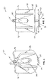
Fig. 1 is a top perspective view of a floor leveling device including a base and a cap. -
Fig. 2 is a side view of the floor leveling device. -
Fig. 3 is a top perspective view of the base. -
Fig. 4 is a side view of the base. -
Fig. 5 is a top view of the base. -
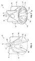
Fig. 6 is a top perspective view of the cap. -
Fig. 7 is a bottom perspective view of the cap. -
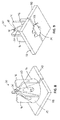
Fig. 8 is a top perspective view of the floor leveling device in use with two tiles. -
Fig. 9 is a bottom perspective view of the floor leveling device in use with two tiles. -
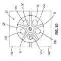
Fig. 10 is a top view of the floor leveling device in use with two tiles. - Before any embodiments of the invention are explained in detail, it is to be understood that the invention is not limited in its application to the details of construction and the arrangement of components set forth in the following description or illustrated in the following drawings. The invention is capable of other embodiments and of being practiced or of being carried out in various ways.
-
Figs. 1-2 illustrate afloor leveling device 20 including abase 24 and acap 28. Thefloor leveling device 20 is usable to help level, for example, tiles on a floor, wall, or other surface. In use, a portion of thebase 24 is positioned beneath the tiles (e.g., between the tiles and the floor), and thecap 28 is moved along another portion of thebase 24 to engage the tiles. Thebase 24 and thecap 28 capture portions of the tiles therebetween to help level and space the tiles relative to each other. Grout, calk, and/or other bonding or adhesive materials introduced underneath and between the tiles to secure the tiles together. - As shown in
Figs. 3-5 , the illustratedbase 24 includes aplate 32 and astem 36. Theplate 32 is the portion of thebase 24 configured to be positioned beneath the tiles. Theplate 32 includes a planarupper surface 40 that is configured to engage the tiles. The illustratedupper surface 40 is planar, or flat, throughout and does not include any bumps or protrusions extending upwardly from thesurface 40. As shown inFig. 2 , theplate 32 also includes two angledlower surfaces central planar section 52 that are opposite the planarupper surface 40. Theangled surfaces central planar section 52. The firstangled surface 44 extends from thecentral planar section 52 to afirst edge 56 of theplate 32, and the secondangled surface 48 extends from thecentral planar section 52 to asecond edge 60 of theplate 32. Thesurfaces upper surface 40 of theplate 32. In the illustrated embodiment, theangled surfaces plate 32 decreases in thickness, or tapers, toward thefirst edge 56 and toward thesecond edge 60. This arrangement provides a wedge-shaped profile toward thefirst edge 56 and thesecond edge 60. - Referring back to
Figs. 3 and 5 , theplate 32 also includes twonotches first notch 64 is formed through the planarupper surface 40 and the first angledlower surface 44 at thefirst edge 56. Thesecond notch 68 is formed through the planarupper surface 40 and the second angledlower surface 48 at thesecond edge 60. In the illustrated embodiment, thenotches notches plate 32 may include fewer or more notches at eachedge Fig. 5 ,sides 72 of theplate 32 are also angled toward thenotches plate 32 decreases toward the first andsecond edges - As shown in
Figs. 3-4 , thestem 36 extends generally perpendicularly from the planarupper surface 40 of theplate 32. The illustratedstem 36 includes a threadedportion 76 and aflattened portion 80. The threadedportion 76 is formed at a distal or free end of thestem 36. The threadedportion 76 includes threads that threadably engage to thecap 28. The threadedportion 76 allows thecap 28 to move along thestem 36 toward and away from theplate 32. In some embodiments, the threadedportion 76 may be replaced with a toothed portion that engages thecap 28 via a ratchet-type mechanism. In the illustrated embodiment, the threadedportion 76 accounts for a majority (i.e., over 50 percent) of the overall length of thestem 36. In some embodiments, the threadedportion 76 may extend the entire length of thestem 36, and the flattenedportion 80 may be omitted. - The flattened
portion 80 is positioned between theplate 32 and the threadedportion 76. The flattenedportion 80 is shaped and sized to create and maintain a desired spacing between adjacent tiles. The illustrated flattenedportion 80 includes two vertically-extending,planar surfaces 84 that are configured to engage and space apart edges of two tiles. Theplanar surfaces 84 provide the flattenedportion 80 with a generally rectangular cross-section to fit between the tiles. In other embodiments, the flattenedportion 80 may have an X- or cross-shaped cross-section to fit between and space apart four tiles at their corners. - As shown in
Fig. 4 , the illustratedbase 24 also includesperforations 88 formed between theplate 32 and thestem 36. In particular, theperforations 88 are formed between theupper surface 40 of theplate 32 and the flattenedportion 80 of thestem 36. Theperforations 88 may be, for example, notches or score lines to remove material between theplate 32 and thestem 36. Theperforations 88 facilitate separating (e.g., snapping apart) thestem 36 from theplate 32. -
Figs. 6 and 7 illustrate thecap 28 of thefloor leveling device 20. Thecap 28 couples to thestem 36 to capture portions of tiles between thecap 28 and theplate 32. In the illustrated embodiment, thecap 28 is threadably coupled to the threadedportion 76 of thestem 36. This threaded connection allows thecap 28 to move along thestem 36 toward and away from theplate 32. - The illustrated
cap 28 includes abody 92, a plurality offlanges 96, and a plurality ofapertures 100. In the illustrated embodiment, thebody 92 is a frustoconically-shaped body having alarger diameter end 104 near theplate 32 of thebase 24, and a smaller diameter end 108 opposite from theplate 32 of thebase 24. Thebody 92 includes a threaded bore 112 (Fig. 6 ) at the smaller diameter end 108. The threaded bore 112 receives and engages the threadedportion 76 of thestem 36. Thebody 92 also includes an inner bore 116 (Fig. 7 ) extending from thelarger diameter end 104 to the threadedbore 112. The inner bore 116 is sized to at least partially receive the flattenedportion 80 of thestem 36 when thecap 28 is threaded onto thestem 36. The inner bore 116 thereby provides clearance in thecap 28 for thecap 28 to fit over the flattenedportion 80 and move closer to theplate 32. - The
flanges 96 extend radially outward from thebody 92. In the illustrated embodiment, thecap 28 includes fiveflanges 96 that are circumferentially spaced around thebody 92. Eachflange 96 provides a handle or grip to facilitate turning thecap 28 on thestem 36 of thebase 24. In other embodiments, thecap 28 may include fewer or more flanges. Additionally or alternatively, theflanges 96 may be spaced in different arrangements around thecap 28. In some embodiments, theflanges 96 may be omitted so that a user directly grasps thebody 92 of thecap 28 to turn thecap 28. - The
apertures 100 are formed through thebody 92. In the illustrated embodiment, thecap 28 includes fiveapertures 100 that are circumferentially spaced around thebody 92 of thecap 28. The illustratedapertures 100 are equally spaced apart such that eachaperture 100 is positioned between twoadjacent flanges 96. In other embodiments, thecap 100 may include fewer or more apertures. Additionally or alternatively, theapertures 100 may be spaced in different arrangements around thecap 28. The illustratedapertures 100 extend in a direction generally parallel to an axis of rotation of the cap 28 (and, thereby, a longitudinal axis of the stem 36). Orienting theapertures 100 in this manner provides a view through thecap 28 so that a user can see areas beneath the cap. More specifically, theapertures 100 allow a user to view portions of the tiles beneath thecap 28 to see, for example, if grout is squeezing out between the tiles underneath thecap 28. - As shown in
Figs. 2 and7 , thecap 28 also includes aridge 120 formed on abottom surface 124 of the body 92 (i.e., the surface of thebody 92 at thelarger diameter end 104 and facing the plate 32). Theridge 120 extends downwardly from thebody 92 toward theplate 32 of thebase 24. In the illustrated embodiment, theridge 120 is a continuous, annular rib formed on thebottom surface 124 of thecap 28. In other embodiments, theridge 120 may include a series of discrete bumps or ribs formed on thebottom surface 124 of thecap 28. Theridge 120 is configured to engage upper surfaces of the tiles when thecap 28 is threaded onto thestem 36 of the base 24 to reduce the chance of grout getting caught between thecap 28 and the tiles. Theridge 120 also reduces friction between thecap 28 and the tiles when spinning thecap 28 onto thebase 24. Furthermore, theridge 120 reduces the possibility of marring the tiles as thecap 28 is spun onto thebase 24. - In the illustrated embodiment, the
base 24 and thecap 28 are composed of plastic (e.g., polyethylene, polyvinyl chloride, nylon, etc.). More particularly, thebase 24 and thecap 28 are made of molded or injection molded plastic. In other embodiments, thebase 24 and thecap 28 may be made of other or differing materials. For example, thebase 24 may be made of plastic, and thecap 28 may be made of metal or wood. Alternatively, thebase 24 and thecap 28 may be made of different types of plastics. -
Figs. 8-10 illustrate thefloor leveling device 20 in use. During use, theplate 32 of thebase 24 is positioned between twoadjacent tiles 128. This may occur by, for example, positioning onetile 128 on a floor (which is coated with grout), sliding approximately half of theplate 32 under thetile 128 so that the flattenedportion 80 of thestem 36 abuts the edge of thetile 128, and positioning theother tile 128 on top of the other half ofplate 32 so that the flattenedportion 80 ofstem 36 abuts the edge of theother tile 128. As theplate 32 is slid under the tile 128 (and theother tile 128 is slid onto the plate 32), the planarupper surface 40 of theplate 32 scrapes grout off of the underside of thetile 128, creating a relatively clean interface between theplate 32 and thetile 128. Thenotches lower surfaces plate 32 also reduce the amount of space taken up by theplate 32 so that excess grout may accumulate within thenotches lower surfaces - After the
plate 32 is installed under thetiles 128, thecap 28 is coupled to thestem 36. In the illustrated embodiment, thecap 28 is threaded (e.g., spun or rotated) onto the threadedportion 76 of thestem 36. As thecap 28 is threaded onto thestem 36, a user can see if any grout is squeezed out from between thetiles 120 using the apertures 100 (as viewed inFig. 10 ). The user can then clean/remove the grout before the grout hardens on the upper surfaces of thetiles 128. Thecap 28 is threaded onto thestem 36 until theridge 120 on thebottom surface 124 engages thetiles 128. Once theridge 120 engages thetiles 128, further tightening of thecap 28 can shift thetiles 128 vertically to help level thetiles 128 relative to each other. This process can be performed on all of thetiles 128 on a floor or other surface. - Once the
tiles 128 are leveled and set (e.g., once the grout hardens), thecap 28 is removed (e.g., unthreaded) from thestem 36 of thebase 24. Then, thestem 36 is separated from theplate 32 by, for example, snapping thestem 36 apart from theplate 32 along the perforations 88 (Fig. 4 ). Once thecap 28 and thestem 36 are removed, gaps between thetiles 128 can be filled with grout. Theplates 32 are left beneath thetiles 128 and covered by the grout. - Various features and advantages of the invention are set forth in the following claims.
Claims (15)
- A floor leveling device for leveling tiles, the floor leveling device comprising:a base including a plate and a stem, the plate having a planar upper surface configured to engage the tiles and an angled lower surface opposite the planar upper surface, the stem extending generally perpendicularly from the planar upper surface; anda cap coupled to the stem for movement along the stem.
- The floor leveling device of claim 1, wherein the plate includes a notch formed through the planar upper surface and the angled lower surface at an edge of the plate.
- The floor leveling device of claim 1, wherein the angled lower surface is a first angled lower surface adjacent a first edge of the plate, and wherein the plate includes a second angled lower surface opposite the planar upper surface and adjacent a second edge of the plate.
- The floor leveling device of claim 3, wherein the first and second angled lower surfaces are oriented so that the plate decreases in thickness toward the first edge and toward the second edge.
- The floor leveling device of claim 1, wherein the stem includes a threaded portion, and wherein the cap is threadably coupled to the threaded portion.
- The floor leveling device of claim 5, wherein the stem also includes a flattened portion positioned between the plate and the threaded portion; wherein optionally the cap includes an inner bore that partially receives the flattened portion of the stem.
- The floor leveling device of claim 1, wherein;
the base includes perforations formed between the plate and the stem to facilitate separating the stem from the plate; and/or
the cap includes an aperture for viewing portions of the tiles beneath the cap. - A floor leveling device for leveling tiles, the floor leveling device comprising:a base including a plate and a stem extending generally perpendicularly from the plate, the stem having a threaded portion; anda cap threadably coupled to the threaded portion of the stem for movement along the stem, the cap including an aperture for viewing portions of the tiles beneath the cap.
- The floor leveling device of claim 8, wherein the cap includes a plurality of apertures for viewing portions of the tiles beneath the cap wherein optionally the plurality of apertures is circumferentially spaced around the cap.
- The floor leveling device of claim 8, wherein the cap includes a flange extending radially outward from the cap.
- The floor leveling device of claim 8, wherein the cap includes a frustoconically-shaped body.
- The floor leveling device of claim 11, wherein the cap also includes a plurality of flanges extending radially outward from the frustoconically-shaped body, and wherein the plurality of flanges is circumferentially spaced around the frustoconically-shaped body; wherein optionally the cap further includes a plurality of apertures formed through the frustoconically-shaped body and positioned between the plurality of flanges.
- The floor leveling device of claim 8, wherein the cap includes a ridge formed on a bottom surface of the cap, and wherein the ridge is configured to engage the tiles; wherein optionally the ridge is a continuous, annular rib formed on the bottom surface of the cap.
- The floor leveling device of claim 8, wherein the stem includes a flattened portion positioned between the plate and the threaded portion, and wherein the cap includes an inner bore that at least partially receives the flattened portion of the stem.
- A floor leveling device for leveling tiles, the floor leveling device comprising:a base including
a plate having a planar upper surface configured to engage the tiles, a first angled lower surface opposite the planar upper surface and adjacent a first edge of the plate, a second angled lower surface opposite the planar upper surface and adjacent a second edge of the plate, a first notch formed through the planar upper surface and the first angled lower surface at the first edge, and a second notch formed through the planar upper surface and the second angled lower surface at the second edge, and
a stem extending generally perpendicularly from the planar upper surface of the plate, the stem including a threaded portion and a flattened portion positioned between the plate and the threaded portion; anda cap threadably coupled to the threaded portion of the stem for movement along the stem, the cap including a plurality of flanges extending radially outward from the cap, a plurality of apertures positioned between the plurality of flanges for viewing portions of the tiles beneath the cap, and a ridge formed on a bottom surface of the cap and configured to engage the tiles.
Applications Claiming Priority (1)
| Application Number | Priority Date | Filing Date | Title |
|---|---|---|---|
| US14/742,229 US20160369518A1 (en) | 2015-06-17 | 2015-06-17 | Floor Leveling Device |
Publications (2)
| Publication Number | Publication Date |
|---|---|
| EP3106586A2 true EP3106586A2 (en) | 2016-12-21 |
| EP3106586A3 EP3106586A3 (en) | 2017-05-10 |
Family
ID=54337637
Family Applications (1)
| Application Number | Title | Priority Date | Filing Date |
|---|---|---|---|
| EP15190475.2A Withdrawn EP3106586A3 (en) | 2015-06-17 | 2015-10-19 | Floor leveling device |
Country Status (3)
| Country | Link |
|---|---|
| US (1) | US20160369518A1 (en) |
| EP (1) | EP3106586A3 (en) |
| CA (2) | CA2909720C (en) |
Cited By (3)
| Publication number | Priority date | Publication date | Assignee | Title |
|---|---|---|---|---|
| EP3511484A1 (en) * | 2018-01-12 | 2019-07-17 | Progress Profiles SPA | Knob for leveling spacer for laying wall tiles, floor tiles and the like |
| WO2020231377A1 (en) * | 2019-05-16 | 2020-11-19 | Sevinc Murat | Leveling and support apparatus |
| WO2021071456A1 (en) * | 2019-10-08 | 2021-04-15 | Sevinc Murat | Leveling tool for building coating materials |
Families Citing this family (22)
| Publication number | Priority date | Publication date | Assignee | Title |
|---|---|---|---|---|
| USD862204S1 (en) | 2015-05-21 | 2019-10-08 | Russo Trading Company, Inc. | Lippage cap |
| USRE49567E1 (en) | 2015-05-21 | 2023-07-04 | Russo Trading Company, Inc. | Tile lippage post |
| USD834922S1 (en) | 2015-05-21 | 2018-12-04 | Russo Trading Company, Inc. | Threaded lippage cap |
| US20190093372A1 (en) * | 2015-05-21 | 2019-03-28 | William P. Russo | Tile Lippage Threaded Post |
| USD856111S1 (en) | 2015-05-21 | 2019-08-13 | Russo Trading Company, Inc. | Tile lippage threaded post |
| EP3298213B1 (en) * | 2015-05-22 | 2020-06-10 | Raimondi S.p.A. | Leveling spacer for the laying of slab products |
| US10407923B2 (en) * | 2015-06-15 | 2019-09-10 | Atr Plastics Pty Ltd | Tile edge setting device and a method of operation thereof |
| WO2017139832A1 (en) * | 2016-02-17 | 2017-08-24 | Clik Tile System Pty Ltd | Tile levelling clip and system |
| USD830161S1 (en) | 2016-11-04 | 2018-10-09 | Russo Trading Company, Inc. | Orientation washer |
| AU2017200815B2 (en) * | 2017-02-06 | 2021-06-24 | Russo Trading Company, Inc. | Tile Lippage Removal System |
| USD832723S1 (en) * | 2017-02-16 | 2018-11-06 | Tti (Macao Commercial Offshore) Limited | Tile spacer |
| USD866297S1 (en) * | 2017-09-15 | 2019-11-12 | Raimondi S.P.A. | Fastening device |
| US10577813B2 (en) * | 2018-02-08 | 2020-03-03 | Tti (Macao Commercial Offshore) Limited | Tile leveling device |
| IT201800003176A1 (en) * | 2018-03-01 | 2019-09-01 | Ghelfi S R L | A KNOB THAT CAN BE COUPLED WITH A TILE LEVELING SPACER FOR LAYING THE LAST ON FLAT SURFACES |
| IT201800003175A1 (en) * | 2018-03-01 | 2019-09-01 | Ghelfi S R L | KNOB THAT CAN BE COUPLED TO A TILE LEVELING SPACER FOR THE RELATIVE LAYING OF THE TILES ON FLAT SURFACES |
| IT201800005212A1 (en) * | 2018-05-09 | 2019-11-09 | LEVELING SPACER DEVICE | |
| USD899236S1 (en) * | 2018-10-16 | 2020-10-20 | Mafi Ab | Fastening device |
| USD911821S1 (en) | 2020-03-02 | 2021-03-02 | Southland Tile Tools & Accessories, Inc | Tile leveler |
| CA3159900A1 (en) | 2020-08-03 | 2022-02-10 | Germans Boada, S.A. | Floor tile levelling device |
| US11428019B2 (en) * | 2020-11-16 | 2022-08-30 | Raimondi S.P.A. | Levelling spacer device |
| US11697942B2 (en) * | 2021-03-22 | 2023-07-11 | Walter Pytlewski | Tile lippage control and tile spacing system and method therefore |
| US20230091132A1 (en) * | 2021-09-21 | 2023-03-23 | Vincenzo Caruso | Systems for leveling tiles |
Family Cites Families (4)
| Publication number | Priority date | Publication date | Assignee | Title |
|---|---|---|---|---|
| ES1070518Y (en) * | 2009-04-17 | 2009-12-21 | Boada Germans Sa | LEVELING DEVICE FOR PLACEMENT OF COATING PARTS |
| ITPD20110295A1 (en) * | 2011-09-20 | 2013-03-21 | Progress Profiles Spa | LEVELING SPACER FOR LAYING TILES, TILES AND SIMILAR WITH LEAKAGE INTERLOCATION |
| JP5546051B2 (en) * | 2012-03-28 | 2014-07-09 | 株式会社川島織物セルコン | Tile construction jig |
| CN203783094U (en) * | 2014-03-31 | 2014-08-20 | 蔡志强 | Ceramic tile leveling assistor |
-
2015
- 2015-06-17 US US14/742,229 patent/US20160369518A1/en not_active Abandoned
- 2015-10-19 EP EP15190475.2A patent/EP3106586A3/en not_active Withdrawn
- 2015-10-21 CA CA2909720A patent/CA2909720C/en active Active
- 2015-10-21 CA CA3107837A patent/CA3107837C/en active Active
Non-Patent Citations (1)
| Title |
|---|
| None |
Cited By (4)
| Publication number | Priority date | Publication date | Assignee | Title |
|---|---|---|---|---|
| EP3511484A1 (en) * | 2018-01-12 | 2019-07-17 | Progress Profiles SPA | Knob for leveling spacer for laying wall tiles, floor tiles and the like |
| US10760284B2 (en) | 2018-01-12 | 2020-09-01 | Progress Profiles Spa | Knob for leveling spacer for laying wall tiles, floor tiles and the like |
| WO2020231377A1 (en) * | 2019-05-16 | 2020-11-19 | Sevinc Murat | Leveling and support apparatus |
| WO2021071456A1 (en) * | 2019-10-08 | 2021-04-15 | Sevinc Murat | Leveling tool for building coating materials |
Also Published As
| Publication number | Publication date |
|---|---|
| CA2909720A1 (en) | 2016-12-17 |
| CA2909720C (en) | 2021-03-16 |
| CA3107837C (en) | 2023-10-24 |
| US20160369518A1 (en) | 2016-12-22 |
| EP3106586A3 (en) | 2017-05-10 |
| CA3107837A1 (en) | 2016-12-17 |
Similar Documents
| Publication | Publication Date | Title |
|---|---|---|
| EP3106586A2 (en) | Floor leveling device | |
| US10577813B2 (en) | Tile leveling device | |
| US11002025B2 (en) | Leveling spacer device | |
| US9689167B2 (en) | Tile leveler | |
| US20160326754A1 (en) | Device for Installing Tiles | |
| CA2805585C (en) | Roof insulation fastening system | |
| JP6263388B2 (en) | Forming apparatus and construction method using the forming apparatus | |
| EP2514886A1 (en) | Auxiliary device for the installation of plate-shaped products for covering floor and/or walls | |
| KR20190119570A (en) | Ceiling structure with increased workability and space utilization and construction method | |
| US7988012B2 (en) | Joint compound container | |
| US5988574A (en) | Furniture glide | |
| US20180361546A1 (en) | Screwing device | |
| EP3483359B1 (en) | Auxiliary device for placing elements in the form of a plate | |
| US20080011428A1 (en) | Adhesive trowel | |
| EP1726738A2 (en) | Leveling support for raised flooring | |
| AT504276B1 (en) | SUPPORT FOR CAVITY FLOORS | |
| DE102014104945B4 (en) | Doormat with liquid storage | |
| US9719266B2 (en) | Surface finishing tool | |
| US10508458B1 (en) | Tile alignment and leveling device and method for using same | |
| AT517826A4 (en) | Device for pressing a skirting board against a wall | |
| US20130164443A1 (en) | Forming Apparatus | |
| DE202019102012U1 (en) | Food processor with sliding aid and sliding aid | |
| EP2055844A2 (en) | Grating fixed with screws | |
| RU224638U1 (en) | Tile leveling device | |
| DE202010008286U1 (en) | suction cup |
Legal Events
| Date | Code | Title | Description |
|---|---|---|---|
| PUAI | Public reference made under article 153(3) epc to a published international application that has entered the european phase |
Free format text: ORIGINAL CODE: 0009012 |
|
| AK | Designated contracting states |
Kind code of ref document: A2 Designated state(s): AL AT BE BG CH CY CZ DE DK EE ES FI FR GB GR HR HU IE IS IT LI LT LU LV MC MK MT NL NO PL PT RO RS SE SI SK SM TR |
|
| AX | Request for extension of the european patent |
Extension state: BA ME |
|
| PUAL | Search report despatched |
Free format text: ORIGINAL CODE: 0009013 |
|
| AK | Designated contracting states |
Kind code of ref document: A3 Designated state(s): AL AT BE BG CH CY CZ DE DK EE ES FI FR GB GR HR HU IE IS IT LI LT LU LV MC MK MT NL NO PL PT RO RS SE SI SK SM TR |
|
| AX | Request for extension of the european patent |
Extension state: BA ME |
|
| RIC1 | Information provided on ipc code assigned before grant |
Ipc: E04F 15/08 20060101AFI20170406BHEP Ipc: E04F 21/00 20060101ALI20170406BHEP |
|
| STAA | Information on the status of an ep patent application or granted ep patent |
Free format text: STATUS: THE APPLICATION IS DEEMED TO BE WITHDRAWN |
|
| 18D | Application deemed to be withdrawn |
Effective date: 20171111 |