EP3106585A1 - Fastening system for decking boards - Google Patents
Fastening system for decking boards Download PDFInfo
- Publication number
- EP3106585A1 EP3106585A1 EP16174143.4A EP16174143A EP3106585A1 EP 3106585 A1 EP3106585 A1 EP 3106585A1 EP 16174143 A EP16174143 A EP 16174143A EP 3106585 A1 EP3106585 A1 EP 3106585A1
- Authority
- EP
- European Patent Office
- Prior art keywords
- support
- washer
- board
- decking
- stem
- Prior art date
- Legal status (The legal status is an assumption and is not a legal conclusion. Google has not performed a legal analysis and makes no representation as to the accuracy of the status listed.)
- Withdrawn
Links
Images


Classifications
-
- E—FIXED CONSTRUCTIONS
- E04—BUILDING
- E04F—FINISHING WORK ON BUILDINGS, e.g. STAIRS, FLOORS
- E04F15/00—Flooring
- E04F15/02—Flooring or floor layers composed of a number of similar elements
- E04F15/02177—Floor elements for use at a specific location
- E04F15/02183—Floor elements for use at a specific location for outdoor use, e.g. in decks, patios, terraces, verandas or the like
-
- E—FIXED CONSTRUCTIONS
- E04—BUILDING
- E04F—FINISHING WORK ON BUILDINGS, e.g. STAIRS, FLOORS
- E04F15/00—Flooring
- E04F15/02—Flooring or floor layers composed of a number of similar elements
- E04F15/02044—Separate elements for fastening to an underlayer
-
- E—FIXED CONSTRUCTIONS
- E04—BUILDING
- E04F—FINISHING WORK ON BUILDINGS, e.g. STAIRS, FLOORS
- E04F15/00—Flooring
- E04F15/02—Flooring or floor layers composed of a number of similar elements
- E04F15/02161—Floor elements with grooved main surface
-
- E—FIXED CONSTRUCTIONS
- E04—BUILDING
- E04F—FINISHING WORK ON BUILDINGS, e.g. STAIRS, FLOORS
- E04F15/00—Flooring
- E04F15/02—Flooring or floor layers composed of a number of similar elements
- E04F15/02044—Separate elements for fastening to an underlayer
- E04F2015/0205—Separate elements for fastening to an underlayer with load-supporting elongated furring elements between the flooring elements and the underlayer
- E04F2015/02066—Separate elements for fastening to an underlayer with load-supporting elongated furring elements between the flooring elements and the underlayer with additional fastening elements between furring elements and flooring elements
- E04F2015/02077—Separate elements for fastening to an underlayer with load-supporting elongated furring elements between the flooring elements and the underlayer with additional fastening elements between furring elements and flooring elements the additional fastening elements located in-between two adjacent flooring elements
- E04F2015/02094—Engaging side grooves running along the whole length of the flooring elements
Definitions
- This invention relates to a fastening system for decking boards/floor boards.
- Decking boards have been used extensively to create raised decks and floors. Decking boards are laid side by side, spaced apart by about 5mm on top of transverse bearers, and are fixed to the bearers using nails.
- a locking support for decking boards or the like including a support element defining a wall portion and at least two generally planar support portions disposed on opposed sides of the wall portion for supporting the underside of a decking board, the wall portion defining a generally cylindrical or part cylindrical recess; and an anchoring element having a generally planar top portion, which is preferably generally semi-circular, and a depending stem, located in the recess, the stem being able to turn in the recess and an aperture extending through the stem for receiving the shaft of a fastening means for fixing the anchoring element relative to the support element.
- the fastening system allows decking boards to be laid and fastened in place but subsequently removed e.g. for replacement or repair, or to allow access to areas covered by the boards.
- Each planar support portion may define an aperture, preferably a generally D-shaped aperture.
- the semi- circular perimeter edge of the top portion of the washer is knurled.
- the washer should preferably be rigid and is typically made of a metal or very strong plastic such as glass reinforced nylon.
- the generally cylindrical or part cylindrical recess defines an upper portion having a larger internal diameter and a lower portion having a smaller internal diameter.
- the stem of the washer is a close fit inside the upper portion of the generally cylindrical or part cylindrical recess.
- the invention provides a method of assembling a floor comprising decking boards defining slots extending along opposed side edges of the board, the floor being supported on bearers using a decking support as described above, comprising the steps of:-
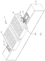
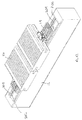
- Figure 1 shows a part of a floor or deck 10.
- the floor includes a series of spaced apart parallel bearers/beams 12, of which only one is shown.
- the bearers may be supported on height adjustable pedestals (not shown), however the specific manner in which the bearers are supported is not critical.
- a series of three support elements 14 (of which one is hidden) are attached to the upper surface of the bearer, on top of which two decking boards 16 are located.
- the support elements are shown in more detail in Figures 3 to 5
- an anchoring element in the form of a washer 18 which locates in the support element, is shown in more detail in Figures 6 to 8 .
- a groove 20 extends along and into each longitudinal side edge of the decking board 16.
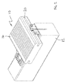
- the support element 14 defines two generally planar portions/platforms 22, on which decking boards are supported in use.
- the planar portions 22 are separated by a wall portion 24 extending across the middle of the support element.
- a large generally D-shaped aperture 25 is defined in the centre of each planar portion 22.
- a series of V-shaped channels 26 are defined in the upper surface of the planar portions which assist in the prevention of water build up under the decking board.
- a V-shaped notch 28 (best seen in Figure 4 ) is defined in each opposed end of the support element 14. This notch assists in aligning the supports on the bearer.
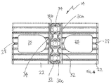
- the wall portion 24 defines three part-cylindrical bores 30, a central bore 30a and a bore 30b, 30c on opposed sides of the central bore.
- the bores are substantially identical.
- Each bore is defined by two opposed part cylindrical surfaces 32.
- two diametrically opposed protrusions 34 are defined in the bore, one protrusion being located in the centre of each part cylindrical surface 32.
- Each bore has a larger diameter upper part 36 and a slightly narrower diameter lower part 38 separated at a circular step 40 (refer to Figure 3 ).
- Figure 5 shows the underside of the support element which defines two longitudinally extending support rails/feet 42, which extend along each of lateral edge of the support element, the lower surfaces of which define a series of spaced V-shaped cut outs 44, and a number of supporting feet 46 under the centre and longitudinal edges of the support element some of whose lower surfaces also define a series of spaced V-shaped cut outs 44.
- the V-shaped cut-outs 44 help to prevent the build of water by allowing freer drainage/movement of water on top of the bearer 12. They also function as cutting grooves to allow a support to be used for an edge or end board by cutting off one of the planar portions.
- FIGs 6 to 8 illustrate the anchoring washer 18 in more detail.
- the washer defines a generally planar top portion 50 and an integral depending stem/support 52.
- the generally planar top portion 50 is generally semi-circular defining a central aperture 54 but with an edge strip 56 disposed to one side of the aperture (refer to Figure 7 ).
- the edge of the curved part of the semi-circular portion is knurled and defines a series of ribs 58.
- An indicia in the form of an arrow 60 is defined pointing to the midpoint of the semi-circular portion.
- the ribs facilitate the turning of the washer using a small screwdriver or similar tool accessing the washer through a gap between boards.
- the depending stem 52 has a generally annular cross-section, but defines two opposed U shaped cut out portions 62 which extend from the base 64 of the stem. Spaced around the exterior of the stem at 90° to the cut out portions are two recesses or indents 66.
- the external diameter of the stem is the approximately the same or slightly smaller than the internal diameter of the bore 30a, so that it is a close fit in the bore 30a but can turn in it, and is greater than the diameter of the bore 30b.
- the stem 52 of the washer 18 locates in the upper bore 36 of one of the bores 30a of the support element.
- the stem of the washer is held aligned with the bore by the fit of the stem of the washer in the bore 30a.
- the diameter of the lower bore of the support element is approximately the external diameter of the helix of the screw so that the screw is a snug fit in the bore.
- a support 14 is located on a bearer 12 and a first board 16 is supported on the planar portions of the support, above the bearer 12.
- the washer 18 is rotated so that half of the semi-circular portion of the washer is located in the groove 20 in the side of the decking board 16, and the arrow 60 is visible adjacent the edge of the board.
- the washer and support 14 may be partly fixed in place by the screw 100 which extends through the stem into the support 14 and into the bearer, but the screw is not fully inserted and the washer remains free to rotate.
- the combination of the two protrusions in the bore 30a and the two recesses 62 and two cut outs 66 provides a series of click stops spaced apart at 90° as the protrusions engage in the recesses or cut-outs.
- a second board (not shown) is then located adjacent the first board on the support and a further support is slipped under the distal side of the second board.
- the washer in the first support is rotated through 90° to the position shown in Figure 10 and the screw is tightened to lock the washer in place. Note that in this position, the arrow 60 is visible.
- the board is then locked in place either side by washers.
- a next board is placed adjacent the second board a support is located under the distal side of the second board and the process is continued until the decking is complete. Where access is only required in certain areas of a deck it is possible to use the washers in those areas and use support elements without washers in other areas and simply nail the boards in place, with the nails passing through sides of the boards and into the D-shaped apertures.
- the support elements also assist in maintaining an even separation between boards.
- the head of the screw is visible between the boards and can be accessed and partially unscrewed to allow rotation of the washer to allow the removal of individual or multiple boards, as illustrated in Figure 11 .
- Figure 12 illustrates a variant of the invention in which a rail 200 is mounted to the top of the bearer using fasteners such as screws.
- the rail defines two parallel longitudinally extending ribs 202, 204.
- the ribs locate between the central supporting feet of the support elements and ensure they are correctly aligned with one another.
- the support elements may be slid along the rails, before they are locked in place by screws.
- the supports may be used with square washers and the like, which do not have the advantage of being removable, but can be used where the boards do not need to be removed. Also the provision of the three bores in the centre of the support, allows the supports to support and fix the ends of two boards butted end to end, simultaneously.
- Figures 13 to 16 show a number of different washer and board combinations using the supports.
- Figure 13 shows the use of a semi-circular washer 18 and a square washer 300 to fix two boards 16 butted end to end.
- Figure 14 shows a similar arrangement, but using two semi-circular washers 18.
- Figure 15 shows a single square washer 300 attached via the central bore 30a of the support, fixing the ends of two boards.
- Figure 16 illustrates the use of two square washers retaining a single board 16. Other arrangements are possible.
Landscapes
- Engineering & Computer Science (AREA)
- Architecture (AREA)
- Civil Engineering (AREA)
- Structural Engineering (AREA)
- Chemical & Material Sciences (AREA)
- Chemical Kinetics & Catalysis (AREA)
- Electrochemistry (AREA)
- Mechanical Engineering (AREA)
- Floor Finish (AREA)
- Bolts, Nuts, And Washers (AREA)
Abstract
A fastening system for decking boards (16) includes a series of supports (14) which attach to a bearer (12). The supports define a central raised wall (24) and two planar portions (22) located either side of the wall. In the centre of the wall there is a cylindrical recess (30) which receives a stem (52) depending from a generally semi-circular washer (18). The stem (52) can rotate in the recess. The decking boards define slots which run along both sides of the board. In use, a first pair of supports is located on a bearer (12) and a first board is supported on the planar portions (22) of the supports, above the bearer. The washer is rotated so that one half of the semi-circular top (50) of one washer extends into the slot in the side of the decking board. The washer is then fixed in place by a screw which extends through the stem into the support and into the bearer. A board is then located adjacent the first board on the support and a further support is slipped under the free side of the board and the washer in the further support is rotated and locked in place with a screw. The heads of the screws are visible between the boards and can be accessed and partially unscrewed to allow rotation of the washer to allow the removal of individual or multiple boards.
Description
- This invention relates to a fastening system for decking boards/floor boards.
- Decking boards have been used extensively to create raised decks and floors. Decking boards are laid side by side, spaced apart by about 5mm on top of transverse bearers, and are fixed to the bearers using nails.
- One problem with current methods for laying decking boards occurs when it is necessary to remove the decking boards, either to replace damaged decking boards, or for access underneath the deck for services or the like. This is difficult to do as it involves removal of a number of boards and the removal of the boards often results in damage to the deck.
- Any discussion of documents, acts, materials, devices, articles or the like which has been included in the present specification is not to be taken as an admission that any or all of these matters form part of the prior art base or were common general knowledge in the field relevant to the present disclosure as it existed before the priority date of each claim of this application.
- Throughout this specification the word "comprise", or variations such as "comprises" or "comprising", will be understood to imply the inclusion of a stated element, integer or step, or group of elements, integers or steps, but not the exclusion of any other element, integer or step, or group of elements, integers or steps.
- According to the present invention, there is provided a locking support for decking boards or the like including a support element defining a wall portion and at least two generally planar support portions disposed on opposed sides of the wall portion for supporting the underside of a decking board, the wall portion defining a generally cylindrical or part cylindrical recess; and an anchoring element having a generally planar top portion, which is preferably generally semi-circular, and a depending stem, located in the recess, the stem being able to turn in the recess and an aperture extending through the stem for receiving the shaft of a fastening means for fixing the anchoring element relative to the support element.
- Advantageously, the fastening system allows decking boards to be laid and fastened in place but subsequently removed e.g. for replacement or repair, or to allow access to areas covered by the boards.
- Each planar support portion may define an aperture, preferably a generally D-shaped aperture.
- Typically, the semi- circular perimeter edge of the top portion of the washer is knurled.
- The washer should preferably be rigid and is typically made of a metal or very strong plastic such as glass reinforced nylon.
- Typically, the generally cylindrical or part cylindrical recess defines an upper portion having a larger internal diameter and a lower portion having a smaller internal diameter. The stem of the washer is a close fit inside the upper portion of the generally cylindrical or part cylindrical recess.
- In a related aspect, the invention provides a method of assembling a floor comprising decking boards defining slots extending along opposed side edges of the board, the floor being supported on bearers using a decking support as described above, comprising the steps of:-
- locating a first pair of supports on a bearer;
- supporting a first board on the planar portions of the supports;
- adjusting the washer so that part of the top portions of one washer extends into a slot in the side of the decking board; and
- fixing the washer using a removable fastener such as a screw extending through the stem into the support and into the bearer.
- A specific embodiment of the present invention will now be described, by way of example only, and with reference to the accompanying drawings, in which:-
-
Figure 1 is an isometric view of part of a raised deck embodying the present invention; -
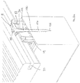
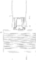
Figure 2 shows a section through the deck shown inFigure 1 ; -
Figure 2a is an enlarged view of part of the section shown inFigure 2 ; -
Figure 3 is an isometric view of a support element of the deck showing the top of the support element; -
Figure 4 is a top plan view of the support element ofFigure 3 ; -
Figure 5 is an isometric view showing the underside of the support element ofFigure 3 ; -
Figure 6 is an isometric view of an anchoring element showing the top of the anchoring element; -
Figure 7 is a top plan view of the anchoring element shown inFigure 6 ; -
Figure 8 is an isometric view showing the underside of the anchoring element shown inFigure 6 ; -
Figure 9 is a top plan view of the deck showing the anchoring element in a first locked position; -
Figure 10 is a top plan view of the deck showing the anchoring element in a second locked position; -
Figure 11 is a top plan view of the deck showing the anchoring element in an unlocked position -
Figure 12 shows a variant of the deck incorporating a rail; and -
Figures 13 to 16 illustrate the use of the support with different combinations and arrangements of washers. - Referring to the drawings,
Figure 1 shows a part of a floor ordeck 10. The floor includes a series of spaced apart parallel bearers/beams 12, of which only one is shown. The bearers may be supported on height adjustable pedestals (not shown), however the specific manner in which the bearers are supported is not critical. - A series of three support elements 14 (of which one is hidden) are attached to the upper surface of the bearer, on top of which two
decking boards 16 are located. The support elements are shown in more detail inFigures 3 to 5 , and an anchoring element in the form of awasher 18 which locates in the support element, is shown in more detail inFigures 6 to 8 . - As can be seen in
Figure 1 , agroove 20 extends along and into each longitudinal side edge of thedecking board 16. - Turning to
Figures 3 to 5 , thesupport element 14 defines two generally planar portions/platforms 22, on which decking boards are supported in use. Theplanar portions 22 are separated by awall portion 24 extending across the middle of the support element. A large generally D-shaped aperture 25 is defined in the centre of eachplanar portion 22. A series of V-shaped channels 26 (best seen inFigure 3 ) are defined in the upper surface of the planar portions which assist in the prevention of water build up under the decking board. A V-shaped notch 28 (best seen inFigure 4 ) is defined in each opposed end of thesupport element 14. This notch assists in aligning the supports on the bearer. Thewall portion 24 defines three part-cylindrical bores 30, acentral bore 30a and abore cylindrical surfaces 32. As is best seen inFigure 4 , two diametrically opposedprotrusions 34 are defined in the bore, one protrusion being located in the centre of each partcylindrical surface 32. Each bore has a larger diameterupper part 36 and a slightly narrower diameterlower part 38 separated at a circular step 40 (refer toFigure 3 ). -
Figure 5 shows the underside of the support element which defines two longitudinally extending support rails/feet 42, which extend along each of lateral edge of the support element, the lower surfaces of which define a series of spaced V-shaped cut outs 44, and a number of supportingfeet 46 under the centre and longitudinal edges of the support element some of whose lower surfaces also define a series of spaced V-shaped cut outs 44. The V-shaped cut-outs 44 help to prevent the build of water by allowing freer drainage/movement of water on top of thebearer 12. They also function as cutting grooves to allow a support to be used for an edge or end board by cutting off one of the planar portions. -
Figures 6 to 8 illustrate theanchoring washer 18 in more detail. The washer defines a generally planartop portion 50 and an integral depending stem/support 52. As is best seen inFigure 7 the generally planartop portion 50 is generally semi-circular defining acentral aperture 54 but with anedge strip 56 disposed to one side of the aperture (refer toFigure 7 ). The edge of the curved part of the semi-circular portion is knurled and defines a series ofribs 58. An indicia in the form of anarrow 60 is defined pointing to the midpoint of the semi-circular portion. In use, the ribs facilitate the turning of the washer using a small screwdriver or similar tool accessing the washer through a gap between boards. - As is best seen in
Figure 8 , the dependingstem 52 has a generally annular cross-section, but defines two opposed U shaped cut outportions 62 which extend from thebase 64 of the stem. Spaced around the exterior of the stem at 90° to the cut out portions are two recesses or indents 66. The external diameter of the stem is the approximately the same or slightly smaller than the internal diameter of thebore 30a, so that it is a close fit in thebore 30a but can turn in it, and is greater than the diameter of thebore 30b. - As is best seen in
Figures 1 ,2 and2a , thestem 52 of thewasher 18 locates in theupper bore 36 of one of thebores 30a of the support element. The stem of the washer is held aligned with the bore by the fit of the stem of the washer in thebore 30a. A fastening means in the form of ascrew 100 having ahead 102,shaft 104, threadedpart 106 andtip 108, locates inside the bore in the stem of the washer. Where the head of the screw joins the stem a radiused portion is defined which allows the screw to be self-centring. The diameter of the lower bore of the support element is approximately the external diameter of the helix of the screw so that the screw is a snug fit in the bore. - In use, with reference to
Figures 9 and10 , asupport 14 is located on abearer 12 and afirst board 16 is supported on the planar portions of the support, above thebearer 12. Thewasher 18 is rotated so that half of the semi-circular portion of the washer is located in thegroove 20 in the side of thedecking board 16, and thearrow 60 is visible adjacent the edge of the board. At this stage the washer andsupport 14 may be partly fixed in place by thescrew 100 which extends through the stem into thesupport 14 and into the bearer, but the screw is not fully inserted and the washer remains free to rotate. Note that as the washer does rotate, the combination of the two protrusions in thebore 30a and the tworecesses 62 and twocut outs 66 provides a series of click stops spaced apart at 90° as the protrusions engage in the recesses or cut-outs. - A second board (not shown) is then located adjacent the first board on the support and a further support is slipped under the distal side of the second board. The washer in the first support is rotated through 90° to the position shown in
Figure 10 and the screw is tightened to lock the washer in place. Note that in this position, thearrow 60 is visible. The board is then locked in place either side by washers. A next board is placed adjacent the second board a support is located under the distal side of the second board and the process is continued until the decking is complete. Where access is only required in certain areas of a deck it is possible to use the washers in those areas and use support elements without washers in other areas and simply nail the boards in place, with the nails passing through sides of the boards and into the D-shaped apertures. The support elements also assist in maintaining an even separation between boards. - The head of the screw is visible between the boards and can be accessed and partially unscrewed to allow rotation of the washer to allow the removal of individual or multiple boards, as illustrated in
Figure 11 . -
Figure 12 illustrates a variant of the invention in which arail 200 is mounted to the top of the bearer using fasteners such as screws. The rail defines two parallellongitudinally extending ribs - While the use of the semi-circular washer allows for the easy removal and replacement of boards, the supports may be used with square washers and the like, which do not have the advantage of being removable, but can be used where the boards do not need to be removed. Also the provision of the three bores in the centre of the support, allows the supports to support and fix the ends of two boards butted end to end, simultaneously.
Figures 13 to 16 show a number of different washer and board combinations using the supports. - In particular,
Figure 13 shows the use of asemi-circular washer 18 and asquare washer 300 to fix twoboards 16 butted end to end.Figure 14 shows a similar arrangement, but using twosemi-circular washers 18. -
Figure 15 shows a singlesquare washer 300 attached via thecentral bore 30a of the support, fixing the ends of two boards.Figure 16 illustrates the use of two square washers retaining asingle board 16. Other arrangements are possible. - It will be appreciated by persons skilled in the art that numerous variations and/or modifications may be made to the above-described embodiments, without departing from the broad general scope of the present disclosure. The present embodiments are, therefore, to be considered in all respects as illustrative and not restrictive.
Claims (11)
- A locking support for decking boards (16) or the like including a support element (14) defining a wall portion (24) and at least two generally planar support portions (22) disposed on opposed sides of the wall portion (24) for supporting the underside of a decking board, the wall portion defining a generally cylindrical or part cylindrical recess (30); and
an anchoring element (18) having a top portion (50) and a depending stem (52), located in the recess, the stem being able to turn in the recess and having an aperture (54) extending through the stem for receiving the shaft of a fastening means (100) for fixing the anchoring element relative to the support element. - A locking support for decking boards as claimed in claim 1 wherein the top portion (50) of the anchoring element is generally planar and generally semi-circular.
- A locking support for decking boards as claimed in any preceding claim wherein each planar support portion of the support element defines an aperture (25).
- A locking support for decking boards as claimed in claim 3 wherein the aperture is generally D-shaped.
- A locking support for decking boards as claimed in any one of claims 2 to 4 wherein the generally semi-circular top portion defines a semi-circular perimeter edge which is knurled and defines a series of ribs (58).
- A locking support for decking boards as claimed in claim 5 including an indicia (60) located part way around the semi-circular perimeter edge of the washer.
- A locking support for decking boards as claimed in any preceding claim wherein the generally cylindrical or part cylindrical recess (30) defines an upper portion having a larger internal diameter (36) and a lower portion (38) having a smaller internal diameter.
- A locking support for decking boards as claimed in claim 7 wherein the stem of the washer is a close fit inside the upper portion of the generally cylindrical or part cylindrical recess.
- A locking support for decking boards as claimed in claim 8 wherein the upper portion of the bore defines an inwardly directed protrusion (34) and the stem of the washer defines a recess (66) which can receive the protrusion when aligned with the same.
- A method of assembling a floor comprising decking boards (16) defining slots extending along opposed side edges of the board, the floor being supported on bearers (12) using a decking support as claimed in any preceding claim, comprising the steps of:-locating a first pair of supports on a bearer;supporting a first board on the planar portions of the supports;adjusting the washer so that part of the top portions of one washer extends into a slot in the side of the decking board andfixing the washer using a removable fastener such as a screw extending through the stem into the support and into the bearer.
- A method as claimed in claim 10 further including the step of;locating a second board adjacent the first board on the supportplacing a further support under the second board and adjusting the washer in the further support and securing the same with removable fasteners such as a screw.
Applications Claiming Priority (1)
| Application Number | Priority Date | Filing Date | Title |
|---|---|---|---|
| AU2015902259A AU2015902259A0 (en) | 2015-06-15 | Fastening system for decking boards |
Publications (1)
| Publication Number | Publication Date |
|---|---|
| EP3106585A1 true EP3106585A1 (en) | 2016-12-21 |
Family
ID=56344977
Family Applications (1)
| Application Number | Title | Priority Date | Filing Date |
|---|---|---|---|
| EP16174143.4A Withdrawn EP3106585A1 (en) | 2015-06-15 | 2016-06-13 | Fastening system for decking boards |
Country Status (2)
| Country | Link |
|---|---|
| US (1) | US20160362902A1 (en) |
| EP (1) | EP3106585A1 (en) |
Cited By (3)
| Publication number | Priority date | Publication date | Assignee | Title |
|---|---|---|---|---|
| WO2019102333A1 (en) | 2017-11-21 | 2019-05-31 | I Deck S.R.L. | Clamp for connecting panels in surface coating structure, and manufacturing method |
| IT201800010700A1 (en) * | 2018-11-29 | 2020-05-29 | Heco Italia Efg S R L | HOOKING GROUP FOR PANELS |
| EP4056783A1 (en) | 2021-03-12 | 2022-09-14 | Forestia | Device for attaching decking boards to a support |
Families Citing this family (15)
| Publication number | Priority date | Publication date | Assignee | Title |
|---|---|---|---|---|
| FR3019201B1 (en) * | 2014-03-28 | 2016-05-06 | Louis Boschian | DEVICE FOR FASTENING CLADDING ELEMENTS ON A LAMBOURDE |
| US9909309B1 (en) * | 2017-01-09 | 2018-03-06 | Wayne Conklin | Glass anchoring system |
| USD1019365S1 (en) * | 2023-05-31 | 2024-03-26 | National Nail Corp. | Fastener positioning device |
| US11261893B2 (en) | 2017-08-15 | 2022-03-01 | National Nail Corp. | Hidden fastener unit and related method of use |
| CN207812930U (en) * | 2017-10-16 | 2018-09-04 | 莫家桂 | A kind of connection structure of high usage timber floor and connection component |
| USD844422S1 (en) * | 2018-03-12 | 2019-04-02 | Jiagui Mo | Fixing device for wooden floor |
| GB2573498B (en) * | 2018-03-16 | 2021-03-17 | John Jarmey Michael | Improved tiling system for decking |
| TWD199562S (en) * | 2018-11-02 | 2019-09-01 | 上昀股份有限公司 | Oblique locking card holder |
| US11359383B2 (en) | 2019-04-23 | 2022-06-14 | Omg, Inc. | Hidden fastener assembly for attaching grooved deck members |
| US11193284B2 (en) * | 2019-05-21 | 2021-12-07 | Silca System, Llc | Tile-securing system and related methods |
| WO2021195462A1 (en) | 2020-03-26 | 2021-09-30 | Omg, Inc. | Deck clip |
| KR102621612B1 (en) * | 2021-12-13 | 2024-01-04 | 문학선 | Deck system with easy replacement and repair of deck using domestically produced wood |
| IT202200011723A1 (en) * | 2022-06-03 | 2023-12-03 | Rotho Blaas Srl Ovvero Rotho Blaas Gmbh | Multi-purpose spacer leveling connector for fixing wooden construction elements such as strips, slats and similar |
| US11999032B2 (en) | 2022-08-02 | 2024-06-04 | National Nail Corp. | Clip starter guide and related method of use |
| USD1022684S1 (en) * | 2023-02-23 | 2024-04-16 | National Nail Corp. | Fastener positioning device |
Citations (5)
| Publication number | Priority date | Publication date | Assignee | Title |
|---|---|---|---|---|
| CN1730863A (en) * | 2004-08-06 | 2006-02-08 | 倪国梁 | Multifunctional floor joist and its assembly |
| EP2275613A2 (en) * | 2009-07-16 | 2011-01-19 | Pinufin Oberflächentechnik GmbH & Co. KG | Cladding composed of profile elements |
| DE202010013171U1 (en) * | 2010-12-21 | 2011-03-03 | Günter Rubner GbR (vertretungsberechtigter Gesellschafter Günter Rubner, 35716 Dietzhölztal-Steinbrücken) | Bohlen fixture |
| FR2960248A1 (en) * | 2010-05-19 | 2011-11-25 | Woodesign | Device for fixing trimming element i.e. blade, to form e.g. wall, has fixing unit cooperated with groove of each trimming element to ensure blocking of element in position and to authorize withdrawal of another element in another position |
| FR2992009A1 (en) * | 2012-06-19 | 2013-12-20 | Ekoresine | Fastening device for fastening mantle blade in e.g. terrace floor on support, has supporting elements attached with retaining element to exert loads against wall portions according to directions that are transverse related to each other |
Family Cites Families (15)
| Publication number | Priority date | Publication date | Assignee | Title |
|---|---|---|---|---|
| ZA94676B (en) * | 1993-02-03 | 1994-08-03 | Rohm & Haas | Reduction of microfoam in spray-applied waterborne composition. |
| CA2287104A1 (en) * | 1999-07-19 | 2001-01-19 | Karl Hermann Werner Gregori | Decking assembly and decking kit with hold-down clip |
| US7908812B2 (en) * | 2002-01-03 | 2011-03-22 | Eberle Harry W Iii | Decking system and anchoring device |
| US6810633B2 (en) * | 2002-08-02 | 2004-11-02 | G. Steven Harris, Sr. | Deck board fastener |
| US6851884B2 (en) * | 2003-03-20 | 2005-02-08 | Blue Heron Enterprises, Llc | Decking anchor device |
| US7578105B2 (en) * | 2003-03-20 | 2009-08-25 | Blue Heron Enterprises, Llc | Expansion-compensating deck fastener |
| US7409803B2 (en) * | 2003-08-05 | 2008-08-12 | Correct Building Products, L.L.C. | Hidden deck fastener system |
| US7052200B2 (en) * | 2003-09-23 | 2006-05-30 | Harris G Steven | Resilient deck board fastener |
| US7398623B2 (en) * | 2004-05-12 | 2008-07-15 | Tiger Claw, Inc. | Deck board fastener with concave prongs |
| US20060283122A1 (en) * | 2005-06-07 | 2006-12-21 | Roy Burgess | Deck system |
| US7984599B2 (en) * | 2006-10-09 | 2011-07-26 | Building Materials Investment Corporation | Hidden decking fastener and related method of fastening deck boards |
| US8066464B1 (en) * | 2008-10-09 | 2011-11-29 | Van Dyke Mark S | Deck fastener |
| US9003624B2 (en) * | 2009-11-25 | 2015-04-14 | Simpson Strong-Tie Company, Inc. | Method for making a gangable composite clip for attaching decking |
| CA2792923C (en) * | 2011-10-27 | 2017-03-28 | Brian Keith Orchard | Clip device for attaching structural member to a supporting structure |
| US9580914B2 (en) * | 2012-10-09 | 2017-02-28 | Craig Warren Richard FOUNTAIN | Fastening means |
-
2016
- 2016-06-08 US US15/177,076 patent/US20160362902A1/en not_active Abandoned
- 2016-06-13 EP EP16174143.4A patent/EP3106585A1/en not_active Withdrawn
Patent Citations (5)
| Publication number | Priority date | Publication date | Assignee | Title |
|---|---|---|---|---|
| CN1730863A (en) * | 2004-08-06 | 2006-02-08 | 倪国梁 | Multifunctional floor joist and its assembly |
| EP2275613A2 (en) * | 2009-07-16 | 2011-01-19 | Pinufin Oberflächentechnik GmbH & Co. KG | Cladding composed of profile elements |
| FR2960248A1 (en) * | 2010-05-19 | 2011-11-25 | Woodesign | Device for fixing trimming element i.e. blade, to form e.g. wall, has fixing unit cooperated with groove of each trimming element to ensure blocking of element in position and to authorize withdrawal of another element in another position |
| DE202010013171U1 (en) * | 2010-12-21 | 2011-03-03 | Günter Rubner GbR (vertretungsberechtigter Gesellschafter Günter Rubner, 35716 Dietzhölztal-Steinbrücken) | Bohlen fixture |
| FR2992009A1 (en) * | 2012-06-19 | 2013-12-20 | Ekoresine | Fastening device for fastening mantle blade in e.g. terrace floor on support, has supporting elements attached with retaining element to exert loads against wall portions according to directions that are transverse related to each other |
Cited By (10)
| Publication number | Priority date | Publication date | Assignee | Title |
|---|---|---|---|---|
| WO2019102333A1 (en) | 2017-11-21 | 2019-05-31 | I Deck S.R.L. | Clamp for connecting panels in surface coating structure, and manufacturing method |
| CN111373108A (en) * | 2017-11-21 | 2020-07-03 | 艾德克有限公司 | Clamp for connecting a panel in a surface covering structure and method for producing the same |
| EP3714117B1 (en) * | 2017-11-21 | 2021-12-01 | I Deck S.r.l. | Clamp for connecting panels in surface coating structure, and manufacturing method |
| CN111373108B (en) * | 2017-11-21 | 2022-01-11 | 艾德克有限公司 | Clamp for connecting a panel in a surface covering structure and method for producing the same |
| US11643807B2 (en) | 2017-11-21 | 2023-05-09 | I Deck S.R.L. | Clamp for connecting panels in surface coating structure, and manufacturing method |
| IT201800010700A1 (en) * | 2018-11-29 | 2020-05-29 | Heco Italia Efg S R L | HOOKING GROUP FOR PANELS |
| EP3660241A1 (en) * | 2018-11-29 | 2020-06-03 | Heco Italia EFG S.r.l. | Coupling unit for panels |
| IL271029B1 (en) * | 2018-11-29 | 2023-07-01 | Heco Italia Efg S R L | Coupling unit for panels |
| EP4056783A1 (en) | 2021-03-12 | 2022-09-14 | Forestia | Device for attaching decking boards to a support |
| FR3120642A1 (en) * | 2021-03-12 | 2022-09-16 | Forestia | Device for fixing decking boards to a support |
Also Published As
| Publication number | Publication date |
|---|---|
| US20160362902A1 (en) | 2016-12-15 |
Similar Documents
| Publication | Publication Date | Title |
|---|---|---|
| EP3106585A1 (en) | Fastening system for decking boards | |
| CA2843068C (en) | Field paver connector and restraining system | |
| US7182661B2 (en) | Detachable surfboard fin system | |
| US20090019805A1 (en) | Nail-Free Decking System | |
| US8910442B2 (en) | Deck board mounting clip | |
| US20110016809A1 (en) | Support pedestal having an anchoring washer for securing elevated surface tiles | |
| US8733031B2 (en) | Attachment member and support structure for supporting a structural building component | |
| US10975567B2 (en) | Extendable sleeve for poured concrete deck | |
| US20160244979A1 (en) | Fasteners for pedestal supported tiles or decking | |
| AU2020203897B2 (en) | Step clip fastening system and method | |
| US20150082735A1 (en) | Post support bracket system | |
| US20190106891A1 (en) | Bridge overhang bracket assembly | |
| US11746533B2 (en) | Step clip fastening system and method | |
| KR101602198B1 (en) | Fastener, deck-member connection and fastening structure using same, and deck-member connection and fastening structure | |
| US4759654A (en) | Clamping device | |
| US12084872B2 (en) | Deck installation device and a method of using said device | |
| US20160340911A1 (en) | Connector assembly for modular ground covering panels | |
| KR101686480B1 (en) | Construction and their restraint system for the floor panel | |
| CA2865147A1 (en) | Extended kerf cut and spline restraint system for elevated flooring surfaces | |
| JP5302662B2 (en) | Deck material mounting structure | |
| US11719002B2 (en) | Flooring board spacing assembly | |
| US7021614B2 (en) | Truss assembly table with wedge set stop members | |
| KR20150102246A (en) | Connective structure of natural wooddeck | |
| US20080017840A1 (en) | Safety rail | |
| US11473248B2 (en) | Modular walkway system |
Legal Events
| Date | Code | Title | Description |
|---|---|---|---|
| PUAI | Public reference made under article 153(3) epc to a published international application that has entered the european phase |
Free format text: ORIGINAL CODE: 0009012 |
|
| STAA | Information on the status of an ep patent application or granted ep patent |
Free format text: STATUS: THE APPLICATION HAS BEEN PUBLISHED |
|
| AK | Designated contracting states |
Kind code of ref document: A1 Designated state(s): AL AT BE BG CH CY CZ DE DK EE ES FI FR GB GR HR HU IE IS IT LI LT LU LV MC MK MT NL NO PL PT RO RS SE SI SK SM TR |
|
| AX | Request for extension of the european patent |
Extension state: BA ME |
|
| STAA | Information on the status of an ep patent application or granted ep patent |
Free format text: STATUS: THE APPLICATION IS DEEMED TO BE WITHDRAWN |
|
| 18D | Application deemed to be withdrawn |
Effective date: 20170622 |