EP3106573A1 - Retaining bracket for a shower hose - Google Patents
Retaining bracket for a shower hose Download PDFInfo
- Publication number
- EP3106573A1 EP3106573A1 EP15172757.5A EP15172757A EP3106573A1 EP 3106573 A1 EP3106573 A1 EP 3106573A1 EP 15172757 A EP15172757 A EP 15172757A EP 3106573 A1 EP3106573 A1 EP 3106573A1
- Authority
- EP
- European Patent Office
- Prior art keywords
- holder
- retaining bracket
- hose
- opening
- retaining
- Prior art date
- Legal status (The legal status is an assumption and is not a legal conclusion. Google has not performed a legal analysis and makes no representation as to the accuracy of the status listed.)
- Granted
Links
Images


Classifications
-
- E—FIXED CONSTRUCTIONS
- E03—WATER SUPPLY; SEWERAGE
- E03C—DOMESTIC PLUMBING INSTALLATIONS FOR FRESH WATER OR WASTE WATER; SINKS
- E03C1/00—Domestic plumbing installations for fresh water or waste water; Sinks
- E03C1/02—Plumbing installations for fresh water
- E03C1/06—Devices for suspending or supporting the supply pipe or supply hose of a shower-bath
-
- E—FIXED CONSTRUCTIONS
- E03—WATER SUPPLY; SEWERAGE
- E03C—DOMESTIC PLUMBING INSTALLATIONS FOR FRESH WATER OR WASTE WATER; SINKS
- E03C1/00—Domestic plumbing installations for fresh water or waste water; Sinks
- E03C1/02—Plumbing installations for fresh water
- E03C1/06—Devices for suspending or supporting the supply pipe or supply hose of a shower-bath
- E03C1/066—Devices for suspending or supporting the supply pipe or supply hose of a shower-bath allowing height adjustment of shower head
Definitions
- the present invention relates to a retaining bracket for a shower hose to be mounted on a holder and having a retaining section and a mounting section.
- retaining rings are very high, if they are to be used in healthcare or nursing homes to avoid backflow from so called category 5 fluid.
- the retaining ring must be designed such that the hose coupling element cannot be moved through the retaining ring.
- the retaining ring may not be loosened from its fixed position simply by hand.
- a retaining bracket for a shower hose to be mounted on a holder and having a retaining section and a mounting section, the retaining section forming an opening for guiding the hose so that the hose is movable in its actual extension through the opening and a hose coupling element connected to the hose is prevented from being moved through the opening, the opening having a lateral aperture so that the hose is to be inserted through the lateral aperture into the opening, wherein the holder can be assembled with the mounting section of the retaining bracket so that the aperture is closed by the assembled holder.
- the hose In the disassembled state the hose can be easily inserted in the guiding opening through the lateral aperture, while it is prevented in particular by the diameter of the opening that the hose can be released from the retaining bracket in the assembled state, because even if the shower hand spray is decoupled from the hose, the hose coupling element cannot be moved through the opening.
- the retaining bracket can easily be fixed with its mount-ing section to the holder, which holder may be mounted in particular to a wall or shower rail in a desired position.
- the opening In the assembled state the opening is delimited by the guiding section and the holder which in particular fully enclose the hose. Principally, the opening may have any desired cross section, wherein it must be provided that in the assembled state the diameter or width of the opening at least at some section need to be chosen such that the hose can move through the opening but that it is prevented that the coupling element can be moved through the opening.
- the coupling elements connected to the ends of the hose are used to couple the hose to the shower hand spray and to a sanitary fitting.
- the retaining bracket is formed in one piece, so that the retaining bracket can be produced easily, wherein the retaining section is arranged adjacent to the mounting section and the lateral aperture is embodied between the retaining section and the mounting section.
- the mounting section and the lateral aperture are formed such that the hose may be placed with its middle section in the height of the lateral aperture and may be inserted through the lateral aperture into the opening by lateral movement.
- the mounting section and the holder are formed in particular in such a way that the mounting section can be assembled on the holder without the aid of a tool.
- the holder is assembled to the mounting section by a positive-locking and/or a non-positive-locking connection, which connection is only to be loosened by a tool.
- positive-locking connection it is implied that the two components are connected to each other in the assembled state due to their respective shape, which prevent a relative movement to each other.
- a non-positive-locking connection is for example a frictional connection. Therefore, the holder and the mounting section are directly connected to each other. By such connections it is avoided that connection elements such as screws are needed to connect the holder and the mounting section to each other.
- the holder is to be mounted to a wall prior to assembling the retaining bracket to the holder, wherein the opening delimited by the retaining section and the holder has a circular cross section after the retaining bracket is assembled to the holder.
- the holder has in particular a ring-shaped or cone-shaped cross section with such a smallest diameter that the hose can move through the opening and the hose coupling element is prevented from being moved through the opening.
- connection between the mounting section and the holder may be provided by a hook that is snapped into a recess, thereby providing a positive-locking connection between the mounting section and the holder.
- the hook is initially deflected by the relative movement of the retaining bracket to the holder and subsequently snaps into the recess, thereby providing a secure connection between the mounting section and the holder.
- connection comprises two oppositely arranged hooks and two respective recesses, wherein the connection can only be released by a special tool comprising two arms which two arms are inserted in the assembled retaining bracket to deflect the two hooks out of the two recesses. If the hooks are deflected out of the recesses, the retaining bracket can be disassembled from the holder. With such a need for a special tool it can be avoided that the retaining bracket can be loosened from the holder only by hand.
- the mounting section forms a rail hole adjacent to the lateral aperture, wherein the rail hole has a larger diameter than an inner diameter of the opening, so that the hose is to be inserted with its hose coupling element through the rail hole and is subsequently laterally to be inserted into the opening, wherein the holder comprises a shower rail that fits frictionally in the rail hole.
- the retaining bracket is preferably formed in one piece providing in the mounting section a hole for receiving the shower rail and forming the opening in an adjacent section, wherein the rail hole and the opening are connected in the disassembled state by the lateral aperture.
- the retaining bracket is formed with a continuous border that provides the rail hole and the opening.
- the aperture is closed by the shower rail, which is inserted into the rail hole. Therefore, the shower hose can be applied to the retaining bracket during installation in the bathroom.
- the holder comprises a ring-shaped adapter piece fitting with its outer diameter frictionally in the rail hole and receiving the shower rail in its inner hole. With the adapter piece the retaining bracket can be mounted to shower rails with different diameters.
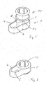
- the retaining bracket 1 depicted in fig. 1 is formed in one piece and has a retaining section 4 forming an opening 6 and a mounting section 5. Between the mounting section 5 and the opening 6 an aperture 8 is provided so that a shower hose 2 may be inserted through the mounting section 5 and the aperture 8 into the opening 6. Furthermore, recesses 10 are formed in the mounting section 5, which interact with hooks 9 of a holder 3, which holder 3 is depicted in fig. 2 .
- the holder 3 comprises a central section, with which the holder 3 is mounted to a wall. At each lateral surfaces a projection and a hook 9 are formed, which interact with the mounting section 5 of the retaining bracket 1, when the retaining bracket 1 is assembled to the holder 3.
- the retaining bracket 1 In fig. 3 the retaining bracket 1, the holder 3, a shower hose 2 with a hose coupling element 7 connected to the shower hose 2 and a special tool 11 with two arms 12 are depicted in a disassembled state.
- the diameter of the hose coupling element 7 is larger than the diameter of the hose 2 and larger than the diameters of the lateral aperture 8 and the opening 6, the retaining bracket 1 can only be applied to the hose 2.
- the holder 3 is mounted to a wall. Subsequently, the hose 2 is inserted into the opening 6 of the retaining bracket 1 passing the mounting section 5 and the lateral aperture 8 of the retaining bracket 1. Afterwards, the retaining bracket 1 is assembled on the holder 3 by moving the retaining bracket 1 downwards onto the holder 3. During the movement of the retaining bracket 1, the hooks 9 on the holder 3 are deflected by the mounting section 5 of the retaining bracket 1 and finally snap into the recesses 10 formed in the mounting section 5 of the retaining bracket 1. Thereby, the retaining bracket 1 is connected to the holder 3 in a positive-locking manner. In this assembled state, the hose 2 is enclosed fully by the retaining section 5 and the assembled holder 3.
- the hose 2 can be moved through the opening 6 delimited by the retaining section 4 and the holder 3 in its axial direction, whereas it is prevented that the coupling elements 7 of the hose 2 can move through the opening 6, as the opening 6 has a smaller inner diameter than the outer diameter of the coupling elements 7.
- the special tool 11 with its arms 12 needs to be inserted into the retaining bracket 1 in order to deflect hooks 9 out of the recesses 10. Subsequently, the retaining bracket 1 can be pulled from the holder 3.
- the second embodiment of a retaining bracket 1 as depicted in figs. 5 - 8 is also formed in one piece comprising a continuous border, which forms a retaining section 4 with an opening 6 and a mounting section 5 with a rail hole 13. Between the opening 6 and the rail hole 13, a lateral aperture 8 is formed by the retaining bracket 1. The lateral aperture 8 is closed, when a shower rail 14 or an adapter piece 15 is assembled in the rail hole 13 as depicted in fig. 6 .
- the shower hose 2 is inserted in a first step with its coupling element 7 through the rail hole 13 and is subsequently laterally displaced with the hose section through the lateral aperture 8 into the opening 6. Subsequently, the adapter piece 15 is inserted into the rail hole 13 thereby preventing that the hose 2 can be released from the retaining bracket 1.
- the retaining bracket 1 is subsequently mounted on a shower rail 14 as depicted in figs. 7 and 8 by inserting the shower rail 14 into the inner hole of the adapter piece 15, where the shower rail 14 is connected to the adapter piece 15 by friction.
- the shower rail 14 has a greater diameter and can be directly mounted in the rail hole 13 of the mounting section 5 of the retaining bracket 1, wherein the mounting section 5 of the retaining bracket 1 and the shower rail 14 are connected due to friction.
- the retaining bracket 1 can be mounted at such a location within the bathroom, that the shower hand spray cannot reach bath tubs, WCs or bidets with possibly contaminated water, wherein the retaining bracket 1 can be mounted easily but cannot be disassembled only by hand.
Landscapes
- Health & Medical Sciences (AREA)
- Life Sciences & Earth Sciences (AREA)
- Engineering & Computer Science (AREA)
- Hydrology & Water Resources (AREA)
- Public Health (AREA)
- Water Supply & Treatment (AREA)
- Domestic Plumbing Installations (AREA)
- Bathtubs, Showers, And Their Attachments (AREA)
- Supports For Pipes And Cables (AREA)
Abstract
Description
- The present invention relates to a retaining bracket for a shower hose to be mounted on a holder and having a retaining section and a mounting section.
- In both standards and certain national regulations of showers and their fittings it is required that the possibility of backflow or back siphonage of eventually contaminated water into the drinking water is avoided. Such a standard is for example EN 1717. As far as mechanical hydraulic protection devices may malfunction, they do not fulfil the requirements of such standards, which for example require a physical air gap. A further possibility to avoid the backflow of the contaminated water is to prevent that the shower hand spray of the shower can reach contaminated water which may be stationary, for example in a bath tub, bidet or toilet. This can be achieved for example, if the shower hose is guided through a retaining ring fixed in such a position that the shower hand spray, which is connected to the shower hose by a hose coupling element, cannot reach the contaminated water. The requirements for such retaining rings are very high, if they are to be used in healthcare or nursing homes to avoid backflow from so called category 5 fluid. For example, the retaining ring must be designed such that the hose coupling element cannot be moved through the retaining ring. Furthermore, the retaining ring may not be loosened from its fixed position simply by hand.
- Therefore, it is an object of the present invention to provide a retaining bracket for a shower hose which can be easily fixed to a desired position and which fulfils the standards to avoid backflow from possibly highly contaminated water.
- This object is solved by a retaining bracket with the features of the independent claim. Favorable embodiments of the retaining bracket are given in the dependent claims and in the description, wherein features of the favorable embodiments can be combined in a technically reasonable manner.
- In particular, the object is solved by a retaining bracket for a shower hose to be mounted on a holder and having a retaining section and a mounting section, the retaining section forming an opening for guiding the hose so that the hose is movable in its actual extension through the opening and a hose coupling element connected to the hose is prevented from being moved through the opening, the opening having a lateral aperture so that the hose is to be inserted through the lateral aperture into the opening, wherein the holder can be assembled with the mounting section of the retaining bracket so that the aperture is closed by the assembled holder.
- In the disassembled state the hose can be easily inserted in the guiding opening through the lateral aperture, while it is prevented in particular by the diameter of the opening that the hose can be released from the retaining bracket in the assembled state, because even if the shower hand spray is decoupled from the hose, the hose coupling element cannot be moved through the opening. At the same time the retaining bracket can easily be fixed with its mount-ing section to the holder, which holder may be mounted in particular to a wall or shower rail in a desired position. By providing the lateral aperture between the opening and the mounting section, only one element is needed to close the lateral aperture and to mount the retaining bracket in a position given by the holder.
- In the assembled state the opening is delimited by the guiding section and the holder which in particular fully enclose the hose. Principally, the opening may have any desired cross section, wherein it must be provided that in the assembled state the diameter or width of the opening at least at some section need to be chosen such that the hose can move through the opening but that it is prevented that the coupling element can be moved through the opening. The coupling elements connected to the ends of the hose are used to couple the hose to the shower hand spray and to a sanitary fitting.
- In particular, the retaining bracket is formed in one piece, so that the retaining bracket can be produced easily, wherein the retaining section is arranged adjacent to the mounting section and the lateral aperture is embodied between the retaining section and the mounting section. Preferably, the mounting section and the lateral aperture are formed such that the hose may be placed with its middle section in the height of the lateral aperture and may be inserted through the lateral aperture into the opening by lateral movement.
- The mounting section and the holder are formed in particular in such a way that the mounting section can be assembled on the holder without the aid of a tool.
- Particularly, the holder is assembled to the mounting section by a positive-locking and/or a non-positive-locking connection, which connection is only to be loosened by a tool. By positive-locking connection it is implied that the two components are connected to each other in the assembled state due to their respective shape, which prevent a relative movement to each other.
- A non-positive-locking connection is for example a frictional connection. Therefore, the holder and the mounting section are directly connected to each other. By such connections it is avoided that connection elements such as screws are needed to connect the holder and the mounting section to each other.
- In a preferred embodiment of the retaining bracket the holder is to be mounted to a wall prior to assembling the retaining bracket to the holder, wherein the opening delimited by the retaining section and the holder has a circular cross section after the retaining bracket is assembled to the holder. The holder has in particular a ring-shaped or cone-shaped cross section with such a smallest diameter that the hose can move through the opening and the hose coupling element is prevented from being moved through the opening. By mounting the holder to a wall, the retaining bracket can be placed at any desirable position within a bathroom.
- The connection between the mounting section and the holder may be provided by a hook that is snapped into a recess, thereby providing a positive-locking connection between the mounting section and the holder.
- In particular, when the retaining bracket with the hose inserted in the opening is mounted to the holder by moving the retaining bracket along the wall to which the holder is mounted, so that the holder is received in the mounting section, a very easy assembling of the retaining bracket is possible. In this regard, it is preferable that the hook is initially deflected by the relative movement of the retaining bracket to the holder and subsequently snaps into the recess, thereby providing a secure connection between the mounting section and the holder.
- In this regard, it is particularly preferable that the connection comprises two oppositely arranged hooks and two respective recesses, wherein the connection can only be released by a special tool comprising two arms which two arms are inserted in the assembled retaining bracket to deflect the two hooks out of the two recesses. If the hooks are deflected out of the recesses, the retaining bracket can be disassembled from the holder. With such a need for a special tool it can be avoided that the retaining bracket can be loosened from the holder only by hand.
- In another preferred embodiment of the retaining bracket, the mounting section forms a rail hole adjacent to the lateral aperture, wherein the rail hole has a larger diameter than an inner diameter of the opening, so that the hose is to be inserted with its hose coupling element through the rail hole and is subsequently laterally to be inserted into the opening, wherein the holder comprises a shower rail that fits frictionally in the rail hole. In this embodiment the retaining bracket is preferably formed in one piece providing in the mounting section a hole for receiving the shower rail and forming the opening in an adjacent section, wherein the rail hole and the opening are connected in the disassembled state by the lateral aperture. Preferably, the retaining bracket is formed with a continuous border that provides the rail hole and the opening. After the shower hose is inserted into the rail hole with its hose coupling element and is subsequently displaced laterally into the opening through the lateral aperture, the aperture is closed by the shower rail, which is inserted into the rail hole. Therefore, the shower hose can be applied to the retaining bracket during installation in the bathroom.
- In order that the retaining bracket can be used with different shower rails, it is suggested that the holder comprises a ring-shaped adapter piece fitting with its outer diameter frictionally in the rail hole and receiving the shower rail in its inner hole. With the adapter piece the retaining bracket can be mounted to shower rails with different diameters.
- The invention and the technical field are described with relation to the drawings, which show preferred embodiments of the retaining bracket. The figures show schematically
- Fig. 1:
- a first embodiment of a retaining bracket,
- Fig. 2:
- a holder for the retaining bracket of the first embodiment,
- Fig. 3:
- an exploded view of a tool, the retaining bracket, the holder and a shower hose,
- Fig. 4:
- the elements of
fig. 3 in an assembled state, - Fig. 5
- a second embodiment of a retaining bracket with an adapter piece in exploded view,
- Fig. 6:
- the retaining bracket and the adapter piece in an assembled state,
- Fig. 7:
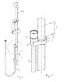
- a shower installation with the second embodiment of the retaining bracket and
- Fig. 8:
- a detail of the shower arrangement with the retaining bracket.
- The
retaining bracket 1 depicted infig. 1 is formed in one piece and has aretaining section 4 forming an opening 6 and a mounting section 5. Between the mounting section 5 and the opening 6 an aperture 8 is provided so that ashower hose 2 may be inserted through the mounting section 5 and the aperture 8 into the opening 6. Furthermore,recesses 10 are formed in the mounting section 5, which interact withhooks 9 of aholder 3, whichholder 3 is depicted infig. 2 . Theholder 3 comprises a central section, with which theholder 3 is mounted to a wall. At each lateral surfaces a projection and ahook 9 are formed, which interact with the mounting section 5 of the retainingbracket 1, when the retainingbracket 1 is assembled to theholder 3. - In
fig. 3 the retainingbracket 1, theholder 3, ashower hose 2 with ahose coupling element 7 connected to theshower hose 2 and a special tool 11 with twoarms 12 are depicted in a disassembled state. As the diameter of thehose coupling element 7 is larger than the diameter of thehose 2 and larger than the diameters of the lateral aperture 8 and the opening 6, the retainingbracket 1 can only be applied to thehose 2. - In a first step, the
holder 3 is mounted to a wall. Subsequently, thehose 2 is inserted into the opening 6 of the retainingbracket 1 passing the mounting section 5 and the lateral aperture 8 of the retainingbracket 1. Afterwards, the retainingbracket 1 is assembled on theholder 3 by moving the retainingbracket 1 downwards onto theholder 3. During the movement of the retainingbracket 1, thehooks 9 on theholder 3 are deflected by the mounting section 5 of the retainingbracket 1 and finally snap into therecesses 10 formed in the mounting section 5 of the retainingbracket 1. Thereby, the retainingbracket 1 is connected to theholder 3 in a positive-locking manner. In this assembled state, thehose 2 is enclosed fully by the retaining section 5 and the assembledholder 3. Thehose 2 can be moved through the opening 6 delimited by the retainingsection 4 and theholder 3 in its axial direction, whereas it is prevented that thecoupling elements 7 of thehose 2 can move through the opening 6, as the opening 6 has a smaller inner diameter than the outer diameter of thecoupling elements 7. - For disassembling the retaining
bracket 1 from theholder 3, the special tool 11 with itsarms 12 needs to be inserted into the retainingbracket 1 in order to deflecthooks 9 out of therecesses 10. Subsequently, the retainingbracket 1 can be pulled from theholder 3. - The second embodiment of a retaining
bracket 1 as depicted infigs. 5 - 8 is also formed in one piece comprising a continuous border, which forms aretaining section 4 with an opening 6 and a mounting section 5 with arail hole 13. Between the opening 6 and therail hole 13, a lateral aperture 8 is formed by the retainingbracket 1. The lateral aperture 8 is closed, when a shower rail 14 or anadapter piece 15 is assembled in therail hole 13 as depicted infig. 6 . - For assembling a
shower hose 2 in the retainingbracket 1 theshower hose 2 is inserted in a first step with itscoupling element 7 through therail hole 13 and is subsequently laterally displaced with the hose section through the lateral aperture 8 into the opening 6. Subsequently, theadapter piece 15 is inserted into therail hole 13 thereby preventing that thehose 2 can be released from the retainingbracket 1. The retainingbracket 1 is subsequently mounted on a shower rail 14 as depicted infigs. 7 and 8 by inserting the shower rail 14 into the inner hole of theadapter piece 15, where the shower rail 14 is connected to theadapter piece 15 by friction. - As can be seen in
fig. 8 , the diameter of the opening 6 is chosen such that thehose 2 may be moved along the opening 6 while it is prevented that thecoupling element 7 is moved through the opening 6 as thecoupling element 7 has a greater diameter than the diameter of the opening 6. The retainingbracket 1 can only be mounted on the shower rail 14 if the shower rail 14 is not yet connected to the wall. This also means that the retainingbracket 1 cannot be disassembled from the shower rail 14 only by hand. - In a not depicted embodiment, the shower rail 14 has a greater diameter and can be directly mounted in the
rail hole 13 of the mounting section 5 of the retainingbracket 1, wherein the mounting section 5 of the retainingbracket 1 and the shower rail 14 are connected due to friction. - The retaining
bracket 1 can be mounted at such a location within the bathroom, that the shower hand spray cannot reach bath tubs, WCs or bidets with possibly contaminated water, wherein the retainingbracket 1 can be mounted easily but cannot be disassembled only by hand. -
- 1
- retaining bracket
- 2
- shower hose
- 3
- holder
- 4
- retaining section
- 5
- mounting section
- 6
- opening
- 7
- hose coupling element
- 8
- aperture
- 9
- hook
- 10
- recess
- 11
- special tool
- 12
- arm
- 13
- rail hole
- 14
- shower rail
- 15
- adapter piece
Claims (8)
- Retaining bracket (1) for a shower hose (2) to be mounted on a holder (3) and having a retaining section (4) and a mounting section (5), the retaining section (4) forming an opening (6) for guiding the hose (2) so that the hose (2) is moveable in its axial extension through the opening (6) and a hose coupling element (7) connected to the hose (2) is prevented from being moved through the opening (6), the opening (6) having a lateral aperture (8) so that the hose (2) is to be inserted through the lateral aperture (8) into the opening (6), wherein the holder (3) can be assembled with the mounting section (5) of the retaining bracket (1) so that the aperture (8) is closed by the assembled holder (3).
- Retaining bracket (1) according to claim 1, wherein the holder (3) is assembled to the mounting section (5) by a positive-locking and/or a non-positive-locking connection, which connection is only to be loosened by a tool.
- Retaining bracket (1) according to claim 1 or 2, wherein the holder (3) is to be mounted to a wall prior to assembling the retaining bracket (1) to the holder (3), wherein the opening (6) delimited by the retaining section (4) and the holder (3) has a circular cross section after the retaining bracket (1) is assembled to the holder (3).
- Retaining bracket (1) according to claim 2 and 3, wherein the connection between the mounting section (5) and the holder (3) is provided by a hook (9) that is snapped into a recess (10).
- Retaining bracket (1) according to claim 4, wherein the retaining bracket (1) with the hose (2) inserted in the opening (6) is mounted to the holder (3) by moving the retaining bracket (1) along the wall to which the holder (3) is mounted, so that the holder (3) is received in the mounting section (5), wherein the hook (9) is initially deflected by the relative movement of the retaining bracket (1) to the holder (3) and subsequently snaps into the recess.
- Retaining bracket (1) according to claim 5, wherein the connection comprises two oppositely arranged hooks (9) and two respective recesses (10), wherein the connection can only be released by a special tool (11) comprising two arms (12) which two arms (12) are inserted in the assembled retaining bracket (1) to deflect the two hooks (9) out of the two recesses (10).
- Retaining bracket (1) according to claim 1 or 2, the mounting section (5) forming a rail hole (13) adjacent to the lateral aperture (8), wherein the rail hole (13) has a larger diameter than an inner diameter of the opening (6), so that the hose (2) is to be inserted with its hose coupling element (7) through the rail hole (13) and is subsequently laterally to be inserted into the opening (6), wherein the holder (3) comprises a shower rail (14) that fits frictionally in the rail hole (13).
- Retaining bracket (1) according to claim 7, wherein the holder (3) comprises a ring-shaped adapter piece (15) fitting with its outer diameter frictionally in the rail hole (13) and receiving the shower rail (14) in its inner hole.
Priority Applications (2)
| Application Number | Priority Date | Filing Date | Title |
|---|---|---|---|
| EP15172757.5A EP3106573B1 (en) | 2015-06-18 | 2015-06-18 | Retaining bracket for a shower hose |
| ES15172757T ES2782423T3 (en) | 2015-06-18 | 2015-06-18 | Retaining pin for a shower hose |
Applications Claiming Priority (1)
| Application Number | Priority Date | Filing Date | Title |
|---|---|---|---|
| EP15172757.5A EP3106573B1 (en) | 2015-06-18 | 2015-06-18 | Retaining bracket for a shower hose |
Publications (2)
| Publication Number | Publication Date |
|---|---|
| EP3106573A1 true EP3106573A1 (en) | 2016-12-21 |
| EP3106573B1 EP3106573B1 (en) | 2020-03-04 |
Family
ID=53488171
Family Applications (1)
| Application Number | Title | Priority Date | Filing Date |
|---|---|---|---|
| EP15172757.5A Active EP3106573B1 (en) | 2015-06-18 | 2015-06-18 | Retaining bracket for a shower hose |
Country Status (2)
| Country | Link |
|---|---|
| EP (1) | EP3106573B1 (en) |
| ES (1) | ES2782423T3 (en) |
Citations (2)
| Publication number | Priority date | Publication date | Assignee | Title |
|---|---|---|---|---|
| GB2419287A (en) * | 2004-10-22 | 2006-04-26 | Kohler Mira Ltd | Shower head mounting |
| WO2008109964A1 (en) * | 2007-03-15 | 2008-09-18 | Luke Mallam | Bracket for soft drink dispenser |
-
2015
- 2015-06-18 ES ES15172757T patent/ES2782423T3/en active Active
- 2015-06-18 EP EP15172757.5A patent/EP3106573B1/en active Active
Patent Citations (2)
| Publication number | Priority date | Publication date | Assignee | Title |
|---|---|---|---|---|
| GB2419287A (en) * | 2004-10-22 | 2006-04-26 | Kohler Mira Ltd | Shower head mounting |
| WO2008109964A1 (en) * | 2007-03-15 | 2008-09-18 | Luke Mallam | Bracket for soft drink dispenser |
Also Published As
| Publication number | Publication date |
|---|---|
| ES2782423T3 (en) | 2020-09-15 |
| EP3106573B1 (en) | 2020-03-04 |
Similar Documents
| Publication | Publication Date | Title |
|---|---|---|
| US10066375B2 (en) | Sanitary fitting for at least two fluids | |
| EP2752526A2 (en) | Device for wall-mounting a sanitary fixture installation structure | |
| WO2020102718A8 (en) | A fixture pod for a lavatory fixture | |
| EP3133304A1 (en) | Retainer for check valve | |
| EP3106573B1 (en) | Retaining bracket for a shower hose | |
| EP2014838B1 (en) | Wall bend fixture for water pipes leading through a wall | |
| US20210254755A1 (en) | Tub and shower fixture block | |
| EP2584106A1 (en) | A quick coupling device for assembling sanitary fittings, such as faucets and the like | |
| PL209265B1 (en) | Outlet system | |
| JP6734504B2 (en) | Remote operated drain plug device | |
| JP2015113629A (en) | Attachment member | |
| US9777877B2 (en) | Pipe connector and arrangement with a pipe connector | |
| WO2008106788A1 (en) | Rinse assembly with live swivel fitting | |
| EP3289146B1 (en) | Valvular device | |
| US7490376B2 (en) | Drain outlet with integral clamp for use with a plumbing fixture | |
| JP6134199B2 (en) | Operating device | |
| AU2016101413A4 (en) | Anti Ligature Fitting | |
| JP6456167B2 (en) | Water discharge device | |
| CA2813010C (en) | Connector for bathtub tailpipe to drain pipe | |
| JP6023927B2 (en) | Release wire insertion fixture | |
| EP2762647A1 (en) | Drainage element for bathroom fixtures fitted with a backflow prevention device | |
| EP3461959B1 (en) | Overflow device | |
| US20070241563A1 (en) | Universal nipple for wall-mountable structures | |
| JP4680755B2 (en) | Installation method of resin pipe on construction wall, resin pipe installation tool, and pipe holding sleeve | |
| CN203755723U (en) | Intelligent integrated bathroom |
Legal Events
| Date | Code | Title | Description |
|---|---|---|---|
| PUAI | Public reference made under article 153(3) epc to a published international application that has entered the european phase |
Free format text: ORIGINAL CODE: 0009012 |
|
| STAA | Information on the status of an ep patent application or granted ep patent |
Free format text: STATUS: THE APPLICATION HAS BEEN PUBLISHED |
|
| AK | Designated contracting states |
Kind code of ref document: A1 Designated state(s): AL AT BE BG CH CY CZ DE DK EE ES FI FR GB GR HR HU IE IS IT LI LT LU LV MC MK MT NL NO PL PT RO RS SE SI SK SM TR |
|
| AX | Request for extension of the european patent |
Extension state: BA ME |
|
| STAA | Information on the status of an ep patent application or granted ep patent |
Free format text: STATUS: REQUEST FOR EXAMINATION WAS MADE |
|
| 17P | Request for examination filed |
Effective date: 20170209 |
|
| RBV | Designated contracting states (corrected) |
Designated state(s): AL AT BE BG CH CY CZ DE DK EE ES FI FR GB GR HR HU IE IS IT LI LT LU LV MC MK MT NL NO PL PT RO RS SE SI SK SM TR |
|
| STAA | Information on the status of an ep patent application or granted ep patent |
Free format text: STATUS: EXAMINATION IS IN PROGRESS |
|
| 17Q | First examination report despatched |
Effective date: 20180720 |
|
| GRAP | Despatch of communication of intention to grant a patent |
Free format text: ORIGINAL CODE: EPIDOSNIGR1 |
|
| STAA | Information on the status of an ep patent application or granted ep patent |
Free format text: STATUS: GRANT OF PATENT IS INTENDED |
|
| INTG | Intention to grant announced |
Effective date: 20191017 |
|
| RIN1 | Information on inventor provided before grant (corrected) |
Inventor name: MOSS, TERENCE |
|
| GRAS | Grant fee paid |
Free format text: ORIGINAL CODE: EPIDOSNIGR3 |
|
| GRAA | (expected) grant |
Free format text: ORIGINAL CODE: 0009210 |
|
| STAA | Information on the status of an ep patent application or granted ep patent |
Free format text: STATUS: THE PATENT HAS BEEN GRANTED |
|
| AK | Designated contracting states |
Kind code of ref document: B1 Designated state(s): AL AT BE BG CH CY CZ DE DK EE ES FI FR GB GR HR HU IE IS IT LI LT LU LV MC MK MT NL NO PL PT RO RS SE SI SK SM TR |
|
| REG | Reference to a national code |
Ref country code: GB Ref legal event code: FG4D |
|
| REG | Reference to a national code |
Ref country code: CH Ref legal event code: EP |
|
| REG | Reference to a national code |
Ref country code: AT Ref legal event code: REF Ref document number: 1240496 Country of ref document: AT Kind code of ref document: T Effective date: 20200315 |
|
| REG | Reference to a national code |
Ref country code: DE Ref legal event code: R096 Ref document number: 602015048032 Country of ref document: DE |
|
| REG | Reference to a national code |
Ref country code: IE Ref legal event code: FG4D |
|
| PG25 | Lapsed in a contracting state [announced via postgrant information from national office to epo] |
Ref country code: NO Free format text: LAPSE BECAUSE OF FAILURE TO SUBMIT A TRANSLATION OF THE DESCRIPTION OR TO PAY THE FEE WITHIN THE PRESCRIBED TIME-LIMIT Effective date: 20200604 Ref country code: FI Free format text: LAPSE BECAUSE OF FAILURE TO SUBMIT A TRANSLATION OF THE DESCRIPTION OR TO PAY THE FEE WITHIN THE PRESCRIBED TIME-LIMIT Effective date: 20200304 Ref country code: RS Free format text: LAPSE BECAUSE OF FAILURE TO SUBMIT A TRANSLATION OF THE DESCRIPTION OR TO PAY THE FEE WITHIN THE PRESCRIBED TIME-LIMIT Effective date: 20200304 |
|
| REG | Reference to a national code |
Ref country code: NL Ref legal event code: MP Effective date: 20200304 |
|
| PG25 | Lapsed in a contracting state [announced via postgrant information from national office to epo] |
Ref country code: GR Free format text: LAPSE BECAUSE OF FAILURE TO SUBMIT A TRANSLATION OF THE DESCRIPTION OR TO PAY THE FEE WITHIN THE PRESCRIBED TIME-LIMIT Effective date: 20200605 Ref country code: HR Free format text: LAPSE BECAUSE OF FAILURE TO SUBMIT A TRANSLATION OF THE DESCRIPTION OR TO PAY THE FEE WITHIN THE PRESCRIBED TIME-LIMIT Effective date: 20200304 Ref country code: LV Free format text: LAPSE BECAUSE OF FAILURE TO SUBMIT A TRANSLATION OF THE DESCRIPTION OR TO PAY THE FEE WITHIN THE PRESCRIBED TIME-LIMIT Effective date: 20200304 Ref country code: SE Free format text: LAPSE BECAUSE OF FAILURE TO SUBMIT A TRANSLATION OF THE DESCRIPTION OR TO PAY THE FEE WITHIN THE PRESCRIBED TIME-LIMIT Effective date: 20200304 Ref country code: BG Free format text: LAPSE BECAUSE OF FAILURE TO SUBMIT A TRANSLATION OF THE DESCRIPTION OR TO PAY THE FEE WITHIN THE PRESCRIBED TIME-LIMIT Effective date: 20200604 |
|
| REG | Reference to a national code |
Ref country code: LT Ref legal event code: MG4D |
|
| REG | Reference to a national code |
Ref country code: ES Ref legal event code: FG2A Ref document number: 2782423 Country of ref document: ES Kind code of ref document: T3 Effective date: 20200915 |
|
| PG25 | Lapsed in a contracting state [announced via postgrant information from national office to epo] |
Ref country code: NL Free format text: LAPSE BECAUSE OF FAILURE TO SUBMIT A TRANSLATION OF THE DESCRIPTION OR TO PAY THE FEE WITHIN THE PRESCRIBED TIME-LIMIT Effective date: 20200304 |
|
| PG25 | Lapsed in a contracting state [announced via postgrant information from national office to epo] |
Ref country code: LT Free format text: LAPSE BECAUSE OF FAILURE TO SUBMIT A TRANSLATION OF THE DESCRIPTION OR TO PAY THE FEE WITHIN THE PRESCRIBED TIME-LIMIT Effective date: 20200304 Ref country code: EE Free format text: LAPSE BECAUSE OF FAILURE TO SUBMIT A TRANSLATION OF THE DESCRIPTION OR TO PAY THE FEE WITHIN THE PRESCRIBED TIME-LIMIT Effective date: 20200304 Ref country code: SM Free format text: LAPSE BECAUSE OF FAILURE TO SUBMIT A TRANSLATION OF THE DESCRIPTION OR TO PAY THE FEE WITHIN THE PRESCRIBED TIME-LIMIT Effective date: 20200304 Ref country code: PT Free format text: LAPSE BECAUSE OF FAILURE TO SUBMIT A TRANSLATION OF THE DESCRIPTION OR TO PAY THE FEE WITHIN THE PRESCRIBED TIME-LIMIT Effective date: 20200729 Ref country code: RO Free format text: LAPSE BECAUSE OF FAILURE TO SUBMIT A TRANSLATION OF THE DESCRIPTION OR TO PAY THE FEE WITHIN THE PRESCRIBED TIME-LIMIT Effective date: 20200304 Ref country code: CZ Free format text: LAPSE BECAUSE OF FAILURE TO SUBMIT A TRANSLATION OF THE DESCRIPTION OR TO PAY THE FEE WITHIN THE PRESCRIBED TIME-LIMIT Effective date: 20200304 Ref country code: IS Free format text: LAPSE BECAUSE OF FAILURE TO SUBMIT A TRANSLATION OF THE DESCRIPTION OR TO PAY THE FEE WITHIN THE PRESCRIBED TIME-LIMIT Effective date: 20200704 Ref country code: SK Free format text: LAPSE BECAUSE OF FAILURE TO SUBMIT A TRANSLATION OF THE DESCRIPTION OR TO PAY THE FEE WITHIN THE PRESCRIBED TIME-LIMIT Effective date: 20200304 |
|
| REG | Reference to a national code |
Ref country code: AT Ref legal event code: MK05 Ref document number: 1240496 Country of ref document: AT Kind code of ref document: T Effective date: 20200304 |
|
| REG | Reference to a national code |
Ref country code: DE Ref legal event code: R097 Ref document number: 602015048032 Country of ref document: DE |
|
| PLBE | No opposition filed within time limit |
Free format text: ORIGINAL CODE: 0009261 |
|
| STAA | Information on the status of an ep patent application or granted ep patent |
Free format text: STATUS: NO OPPOSITION FILED WITHIN TIME LIMIT |
|
| PG25 | Lapsed in a contracting state [announced via postgrant information from national office to epo] |
Ref country code: DK Free format text: LAPSE BECAUSE OF FAILURE TO SUBMIT A TRANSLATION OF THE DESCRIPTION OR TO PAY THE FEE WITHIN THE PRESCRIBED TIME-LIMIT Effective date: 20200304 Ref country code: AT Free format text: LAPSE BECAUSE OF FAILURE TO SUBMIT A TRANSLATION OF THE DESCRIPTION OR TO PAY THE FEE WITHIN THE PRESCRIBED TIME-LIMIT Effective date: 20200304 Ref country code: MC Free format text: LAPSE BECAUSE OF FAILURE TO SUBMIT A TRANSLATION OF THE DESCRIPTION OR TO PAY THE FEE WITHIN THE PRESCRIBED TIME-LIMIT Effective date: 20200304 |
|
| REG | Reference to a national code |
Ref country code: CH Ref legal event code: PL |
|
| 26N | No opposition filed |
Effective date: 20201207 |
|
| PG25 | Lapsed in a contracting state [announced via postgrant information from national office to epo] |
Ref country code: PL Free format text: LAPSE BECAUSE OF FAILURE TO SUBMIT A TRANSLATION OF THE DESCRIPTION OR TO PAY THE FEE WITHIN THE PRESCRIBED TIME-LIMIT Effective date: 20200304 Ref country code: SI Free format text: LAPSE BECAUSE OF FAILURE TO SUBMIT A TRANSLATION OF THE DESCRIPTION OR TO PAY THE FEE WITHIN THE PRESCRIBED TIME-LIMIT Effective date: 20200304 |
|
| PG25 | Lapsed in a contracting state [announced via postgrant information from national office to epo] |
Ref country code: LU Free format text: LAPSE BECAUSE OF NON-PAYMENT OF DUE FEES Effective date: 20200618 |
|
| REG | Reference to a national code |
Ref country code: BE Ref legal event code: MM Effective date: 20200630 |
|
| PG25 | Lapsed in a contracting state [announced via postgrant information from national office to epo] |
Ref country code: LI Free format text: LAPSE BECAUSE OF NON-PAYMENT OF DUE FEES Effective date: 20200630 Ref country code: IE Free format text: LAPSE BECAUSE OF NON-PAYMENT OF DUE FEES Effective date: 20200618 Ref country code: CH Free format text: LAPSE BECAUSE OF NON-PAYMENT OF DUE FEES Effective date: 20200630 |
|
| PG25 | Lapsed in a contracting state [announced via postgrant information from national office to epo] |
Ref country code: BE Free format text: LAPSE BECAUSE OF NON-PAYMENT OF DUE FEES Effective date: 20200630 |
|
| PG25 | Lapsed in a contracting state [announced via postgrant information from national office to epo] |
Ref country code: MT Free format text: LAPSE BECAUSE OF FAILURE TO SUBMIT A TRANSLATION OF THE DESCRIPTION OR TO PAY THE FEE WITHIN THE PRESCRIBED TIME-LIMIT Effective date: 20200304 Ref country code: CY Free format text: LAPSE BECAUSE OF FAILURE TO SUBMIT A TRANSLATION OF THE DESCRIPTION OR TO PAY THE FEE WITHIN THE PRESCRIBED TIME-LIMIT Effective date: 20200304 |
|
| PG25 | Lapsed in a contracting state [announced via postgrant information from national office to epo] |
Ref country code: MK Free format text: LAPSE BECAUSE OF FAILURE TO SUBMIT A TRANSLATION OF THE DESCRIPTION OR TO PAY THE FEE WITHIN THE PRESCRIBED TIME-LIMIT Effective date: 20200304 Ref country code: AL Free format text: LAPSE BECAUSE OF FAILURE TO SUBMIT A TRANSLATION OF THE DESCRIPTION OR TO PAY THE FEE WITHIN THE PRESCRIBED TIME-LIMIT Effective date: 20200304 |
|
| PGFP | Annual fee paid to national office [announced via postgrant information from national office to epo] |
Ref country code: FR Payment date: 20250625 Year of fee payment: 11 |
|
| PGFP | Annual fee paid to national office [announced via postgrant information from national office to epo] |
Ref country code: TR Payment date: 20250618 Year of fee payment: 11 |
|
| PGFP | Annual fee paid to national office [announced via postgrant information from national office to epo] |
Ref country code: ES Payment date: 20250701 Year of fee payment: 11 |
|
| PGFP | Annual fee paid to national office [announced via postgrant information from national office to epo] |
Ref country code: IT Payment date: 20250619 Year of fee payment: 11 |
|
| REG | Reference to a national code |
Ref country code: DE Ref legal event code: R082 Ref document number: 602015048032 Country of ref document: DE Representative=s name: DIPAS PATENTANWALTS GMBH, DE |
|
| PGFP | Annual fee paid to national office [announced via postgrant information from national office to epo] |
Ref country code: GB Payment date: 20260629 Year of fee payment: 12 |
|
| PGFP | Annual fee paid to national office [announced via postgrant information from national office to epo] |
Ref country code: DE Payment date: 20260629 Year of fee payment: 12 |