EP3106280B1 - Verbundstrukturherstellungssysteme und -verfahren - Google Patents
Verbundstrukturherstellungssysteme und -verfahren Download PDFInfo
- Publication number
- EP3106280B1 EP3106280B1 EP16174447.9A EP16174447A EP3106280B1 EP 3106280 B1 EP3106280 B1 EP 3106280B1 EP 16174447 A EP16174447 A EP 16174447A EP 3106280 B1 EP3106280 B1 EP 3106280B1
- Authority
- EP
- European Patent Office
- Prior art keywords
- ply
- carrier
- elongate
- segment
- kitting
- Prior art date
- Legal status (The legal status is an assumption and is not a legal conclusion. Google has not performed a legal analysis and makes no representation as to the accuracy of the status listed.)
- Active
Links
Images


Classifications
-
- B—PERFORMING OPERATIONS; TRANSPORTING
- B29—WORKING OF PLASTICS; WORKING OF SUBSTANCES IN A PLASTIC STATE IN GENERAL
- B29C—SHAPING OR JOINING OF PLASTICS; SHAPING OF MATERIAL IN A PLASTIC STATE, NOT OTHERWISE PROVIDED FOR; AFTER-TREATMENT OF THE SHAPED PRODUCTS, e.g. REPAIRING
- B29C70/00—Shaping composites, i.e. plastics material comprising reinforcements, fillers or preformed parts, e.g. inserts
- B29C70/04—Shaping composites, i.e. plastics material comprising reinforcements, fillers or preformed parts, e.g. inserts comprising reinforcements only, e.g. self-reinforcing plastics
- B29C70/28—Shaping operations therefor
- B29C70/30—Shaping by lay-up, i.e. applying fibres, tape or broadsheet on a mould, former or core; Shaping by spray-up, i.e. spraying of fibres on a mould, former or core
- B29C70/38—Automated lay-up, e.g. using robots, laying filaments according to predetermined patterns
- B29C70/386—Automated tape laying [ATL]
-
- B—PERFORMING OPERATIONS; TRANSPORTING
- B29—WORKING OF PLASTICS; WORKING OF SUBSTANCES IN A PLASTIC STATE IN GENERAL
- B29C—SHAPING OR JOINING OF PLASTICS; SHAPING OF MATERIAL IN A PLASTIC STATE, NOT OTHERWISE PROVIDED FOR; AFTER-TREATMENT OF THE SHAPED PRODUCTS, e.g. REPAIRING
- B29C31/00—Handling, e.g. feeding of the material to be shaped, storage of plastics material before moulding; Automation, i.e. automated handling lines in plastics processing plants, e.g. using manipulators or robots
- B29C31/04—Feeding of the material to be moulded, e.g. into a mould cavity
- B29C31/08—Feeding of the material to be moulded, e.g. into a mould cavity of preforms to be moulded, e.g. tablets, fibre reinforced preforms, extruded ribbons, tubes or profiles; Manipulating means specially adapted for feeding preforms, e.g. supports conveyors
-
- B—PERFORMING OPERATIONS; TRANSPORTING
- B29—WORKING OF PLASTICS; WORKING OF SUBSTANCES IN A PLASTIC STATE IN GENERAL
- B29C—SHAPING OR JOINING OF PLASTICS; SHAPING OF MATERIAL IN A PLASTIC STATE, NOT OTHERWISE PROVIDED FOR; AFTER-TREATMENT OF THE SHAPED PRODUCTS, e.g. REPAIRING
- B29C65/00—Joining or sealing of preformed parts, e.g. welding of plastics materials; Apparatus therefor
- B29C65/02—Joining or sealing of preformed parts, e.g. welding of plastics materials; Apparatus therefor by heating, with or without pressure
-
- B—PERFORMING OPERATIONS; TRANSPORTING
- B29—WORKING OF PLASTICS; WORKING OF SUBSTANCES IN A PLASTIC STATE IN GENERAL
- B29C—SHAPING OR JOINING OF PLASTICS; SHAPING OF MATERIAL IN A PLASTIC STATE, NOT OTHERWISE PROVIDED FOR; AFTER-TREATMENT OF THE SHAPED PRODUCTS, e.g. REPAIRING
- B29C70/00—Shaping composites, i.e. plastics material comprising reinforcements, fillers or preformed parts, e.g. inserts
- B29C70/04—Shaping composites, i.e. plastics material comprising reinforcements, fillers or preformed parts, e.g. inserts comprising reinforcements only, e.g. self-reinforcing plastics
- B29C70/28—Shaping operations therefor
- B29C70/30—Shaping by lay-up, i.e. applying fibres, tape or broadsheet on a mould, former or core; Shaping by spray-up, i.e. spraying of fibres on a mould, former or core
- B29C70/38—Automated lay-up, e.g. using robots, laying filaments according to predetermined patterns
- B29C70/386—Automated tape laying [ATL]
- B29C70/388—Tape placement heads, e.g. component parts, details or accessories
-
- B—PERFORMING OPERATIONS; TRANSPORTING
- B29—WORKING OF PLASTICS; WORKING OF SUBSTANCES IN A PLASTIC STATE IN GENERAL
- B29L—INDEXING SCHEME ASSOCIATED WITH SUBCLASS B29C, RELATING TO PARTICULAR ARTICLES
- B29L2031/00—Other particular articles
- B29L2031/30—Vehicles, e.g. ships or aircraft, or body parts thereof
- B29L2031/3076—Aircrafts
- B29L2031/3082—Fuselages
-
- B—PERFORMING OPERATIONS; TRANSPORTING
- B29—WORKING OF PLASTICS; WORKING OF SUBSTANCES IN A PLASTIC STATE IN GENERAL
- B29L—INDEXING SCHEME ASSOCIATED WITH SUBCLASS B29C, RELATING TO PARTICULAR ARTICLES
- B29L2031/00—Other particular articles
- B29L2031/30—Vehicles, e.g. ships or aircraft, or body parts thereof
- B29L2031/3076—Aircrafts
- B29L2031/3085—Wings
-
- Y—GENERAL TAGGING OF NEW TECHNOLOGICAL DEVELOPMENTS; GENERAL TAGGING OF CROSS-SECTIONAL TECHNOLOGIES SPANNING OVER SEVERAL SECTIONS OF THE IPC; TECHNICAL SUBJECTS COVERED BY FORMER USPC CROSS-REFERENCE ART COLLECTIONS [XRACs] AND DIGESTS
- Y02—TECHNOLOGIES OR APPLICATIONS FOR MITIGATION OR ADAPTATION AGAINST CLIMATE CHANGE
- Y02T—CLIMATE CHANGE MITIGATION TECHNOLOGIES RELATED TO TRANSPORTATION
- Y02T50/00—Aeronautics or air transport
- Y02T50/40—Weight reduction
Definitions
- the present disclosure relates to composite structure fabrication systems and methods.
- Traditional manufacturing methods for fabricating composite structures include manually locating a plurality of plies of composite material on a layup mandrel to produce and/or define a composite layup. The composite layup subsequently is cured, on the layup mandrel, to produce and/or define the composite structure. While such traditional manufacturing methods may be effective at producing smaller composite structures, they may be inefficient when applied to producing larger composite structures. As an example, a manufacturing floor space needed to fabricate large composite structures utilizing traditional manufacturing methods may be substantial. As another example, an amount of time required to fabricate large composite structures utilizing traditional manufacturing methods may be quite large.
- US2014/065354 in accordance with its abstract, states a method is provided of fabricating a composite stiffener having a curved web and at least one curved flange.
- a substantially straight length of unidirectional prepreg tape is placed on a carrier.
- the at least one curved flange is formed by using the carrier to steer a first portion of the tape onto a first curved tool surface.
- the curved web is formed by using the carrier to form a second portion of the tape onto a second curved tool surface.
- a composite structure fabrication system comprising: a plurality of ply carriers, wherein each ply carrier of the plurality of ply carriers defines a ply support surface configured to temporarily support at least one ply segment; an elongate forming mandrel that defines an elongate ply forming surface, wherein the elongate ply forming surface is shaped to define a surface contour of a composite structure and is configured to receive a plurality of ply segments to define a plurality of plies of composite material that at least partially defines the composite structure; a carrier transfer device configured to selectively convey a selected ply carrier of the plurality of ply carriers from a ply kitting area to an intermediate location and to return the selected ply carrier to the ply kitting area; and a forming machine configured to receive the selected ply carrier at the intermediate location, wherein the forming machine is an automated forming machine including a forming machine translation device configured to selectively translate the forming machine to
- a method of fabricating a composite structure comprising: conveying a selected ply carrier from a ply kitting area to a selected location along a length of an elongate forming mandrel that defines an elongate ply forming surface, wherein the elongate ply forming surface is shaped to define a surface contour of a composite structure and is configured to receive a plurality of ply segments to define a plurality of plies of composite material that at least partially defines the composite structure; translating a forming machine along the length of the elongate forming mandrel to the selected location; receiving the selected ply carrier with the forming machine; deforming, with the forming machine, the selected ply carrier and a respective ply segment, which is supported by the selected ply carrier, over a selected portion of the elongate ply forming surface; releasing the respective ply segment from the selected ply carrier while retaining the respective ply segment on the selected
- Figs. 1-15 provide examples of composite structure fabrication systems 18, according to the present disclosure, of methods 300, according to the present disclosure, and/or of composite structures 800 and/or uncured composite structures 810 that may be produced and/or fabricated utilizing systems 18 and/or methods 300.
- Elements that serve a similar, or at least substantially similar, purpose are labeled with like numbers in each of Figs. 1-15 , and these elements may not be discussed in detail herein with reference to each of Figs. 1-15 .
- all elements may not be labeled in each of Figs. 1-15 , but reference numerals associated therewith may be utilized herein for consistency.
- Elements, components, and/or features that are discussed herein with reference to one or more of Figs. 1-15 may be included in and/or utilized with any of Figs. 1-15 without departing from the scope of the present disclosure.
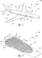
- Fig. 1 is an example of an aircraft 700 that includes a composite structure 800 that may be at least partially constructed utilizing systems 18 and/or methods 300, according to the present disclosure.
- Fig. 2 is an example of a wing 740 that may form a portion of aircraft 700.
- Aircraft 700 may include a plurality of components, including an airframe 710, a fuselage 720, a fuselage barrel 730, wing 740, and/or a stabilizer 750.
- Composite structure 800 of aircraft 700 may include a plurality of plies 90 of composite material, which may form a portion of any suitable component of aircraft 700.
- aircraft 700 may include skin segments 790 that may form, cover, and/or be an outer surface of any suitable portion of aircraft 700 and/or a plurality of stringers 770 that, together with a plurality of frames 780, may support an inner surface of skin segments 790.
- wing 740 may include a plurality of wing stringers 742, which may extend along a length of the wing. Wing 740 also may include a plurality of ribs 744.
- Wing stringers 742 and ribs 744 together may form and/or define at least a portion of an inner support structure 746 for wing 700, which may support an inner surface 748 of skin segments 790 that cover wing 740. These skin segments also may be referred to herein as wing skin segments 790. It is within the scope of the present disclosure that skin segments 790 (or wing skin segments 790), stringers 770, frames 780, wing stringers 742, ribs 744, and/or inner support structure 746 may be at least partially, or even completely, produced from plies 90 of composite material.
- Fig. 3 is a schematic representation of a composite structure fabrication system 18, according to the present disclosure.
- Composite structure fabrication system 18 also may be referred to herein as a fabrication system 18, an elongate composite structure fabrication system 18, and/or a system 18.
- system 18 includes a plurality of ply carriers 20, an elongate forming mandrel 32, a carrier transfer device 40, and a forming machine 50.
- Each ply carrier 20 includes and/or defines a ply support surface 22, which is configured to at least temporarily support one or more ply segments 92.
- Ply segments 92 may be created from a composite material and may be laid-up, built-up, located, placed, and/or layered on elongate forming mandrel 32 to produce and/or define an uncured composite structure 810, which may be cured to produce a composite structure 800, as discussed in more detail herein.
- Elongate forming mandrel 32 defines an elongate ply forming surface 34.
- Elongate ply forming surface 34 is shaped to define a surface contour of composite structure 800 and is configured to receive and/or support a plurality of ply segments 92.
- System 18 optionally may include additional structures, components, and/or features and/or may perform additional functions, as discussed in more detail herein.
- carrier transfer device 40 is configured to selectively convey a selected ply carrier 21, together with one or more respective ply segments 92 that may be supported by selected ply carrier 21, from a ply kitting area 100 and/or from a ply carrier staging area 102 thereof to an intermediate location 180.
- intermediate location 180 may include and/or be a predetermined, preselected, and/or selected location 36 along the length of elongate forming mandrel 32.
- intermediate location 180 may include and/or be ply carrier staging area 102 and/or another ply carrier staging area that is spaced-apart from ply carrier staging area 102.
- Forming machine 50 is configured to receive selected ply carrier 21 at intermediate location 180 and to deform selected ply carrier 21, together with the one or more respective ply segments 92, over a selected portion 38 of elongate ply forming surface 34. During this deformation process, the one or more respective ply segments 92 may be located between selected ply carrier 21 and selected portion 38 of elongate ply forming surface 34. Subsequently, forming machine 50 separates selected ply carrier 21 from the respective ply segment 92 such that respective ply segment 92 is supported by selected portion 38 of elongate ply forming surface 34. The carrier transfer device 40, may return selected ply carrier 21 to ply carrier staging area 102.
- the above-described process is repeated any suitable number of times to locate any suitable number of ply segments 92 on elongate ply forming surface 34.
- the forming machine 50 is configured to translate along the length of elongate forming mandrel 32 and to receive and deform a plurality of selected ply carriers 21 and respective ply segments 92 and at a plurality of different selected locations 36 along the length of elongate forming mandrel 32.
- This is illustrated in Fig. 3 by forming machine 50 translating between a first selected location (with forming machine 50 illustrated in dash-dot lines) and a second selected location (with forming machine 50 illustrated in solid lines).
- the dash-dot lines in Fig. 3 may indicate that a single elongate forming mandrel 32 may have a plurality of forming machines 50 associated therewith.
- This motion of forming machine 50 may permit ply segments 92 to be located and/or placed end-to-end along a length of elongate ply forming surface 34 to generate, create, and/or define a given ply 90, or layer 90, of uncured composite structure 810. Additionally or alternatively, ply segments 92 may be located and/or placed in an overlapping, stacked, or layered, fashion on elongate ply forming surface 34 to generate, create, and/or define a plurality of different, or layered, plies 90 of uncured composite structure 810.
- system 18 further may include a plurality of ply kitting tools 60.
- Ply kitting tools 60 may be adapted, configured, designed, and/or constructed tocreate ply segments 92, such as by cutting ply segments 92 from a composite feedstock 88 of composite material.
- Ply kitting tools 60 may be automated.
- ply kitting tools 60 also may be referred to herein as automated ply kitting tools 60 and/or as numerically controlled ply kitting tools 60.
- ply kitting tools 60 may include and/or be a plurality of ply kitting robots 62.
- ply segments 92 may have and/or define a plurality of different configurations. As examples, different ply segments 92 may be shaped to be received on a specific and/or predetermined portion of elongate ply forming surface 34 and/or may be shaped to define a specific portion of uncured composite structure 810. As such, different ply segments 92 may have and/or define different shapes, compositions, and/or different fiber orientations and/or may be created from different composite feedstocks 88.
- each ply kitting tool 60 may be adapted, configured, and/or programmed to create and/or define a respective ply segment 92, such as may have a given, or predetermined, shape, composition, and/or fiber orientation.
- each ply kitting tool 60 may be adapted, configured, and/or programmed to operate independently from a remainder of the ply kitting tools 60.
- ply kitting tools 60 may be configured to operate, or to create respective ply segments 92, at least partially concurrently with one another.
- ply segments 92 that are concurrently created and/or defined by ply kitting tools 60 may have and/or define a plurality of different configurations, and systems 18 may be configured to track a location of, or maintain an inventory of, individual ply segments 92, as discussed in more detail herein.
- system 18 further may include a plurality of ply segment locating devices 70.
- Ply segment locating devices 70 may be configured to locate at least one ply segment 92 on each ply carrier 20. It is within the scope of the present disclosure that a given ply segment locating device 70 may be separate and/or distinct from a corresponding ply kitting tool 60. However, it is also within the scope of the present disclosure that the given ply segment locating device 70 may form a portion of the corresponding ply kitting tool 60.
- Ply segment locating device 70 may locate and/or place ply segments 92 on ply carriers 20 subsequent to creation of ply segments 92 by ply kitting tools 60. Additionally or alternatively, ply segment locating device 70 may locate and/or place composite feedstock 88 on ply carriers 20, with composite feedstock 88 subsequently being modified to create one or more ply segments 92 by ply kitting tool 60.
- Ply segment locating device 70 may be automated. As such, ply segment locating device 70 also may be referred to herein as automated ply segment locating device 70 and/or as numerically controlled ply segment locating device 70. As an example, ply segment locating device 70 may include and/or be a ply locating robot 72.
- Ply segment locating device 70 may be configured to vacuum compact ply segments 92 onto corresponding ply carriers 20. As such, ply segment locating device 70 may include and/or be associated with a segment vacuum compaction structure 74.
- a given ply segment locating device 70 may be configured to locate any suitable number of ply segments 92 on a given ply carrier 20.
- the given ply segment locating device may be configured to locate a single ply segment 92 on the given ply carrier 20.
- the given ply segment locating device may be configured to locate at least two ply segments 92 on the given ply carrier 20.
- the two or more ply segments 92 may be located in any suitable manner.
- the two or more ply segments 92 may be located such that they define a plurality of stacked ply segments 92.
- the two or more ply segments 92 may be located in a spaced-apart manner on the given ply carrier 20.
- a first fiber orientation of a first ply segment 92 that is supported by the given ply carrier 20 may be different from a second fiber orientation of a second ply segment 92 that is supported by the given ply carrier 20.
- system 18 may include a plurality of ply carrier magazines 28.
- Each ply carrier magazine 28 may be configured to contain, house, enclose, and/or otherwise support a respective plurality of ply carriers 20 and corresponding ply segment(s) 92 that may be supported thereby.
- each ply carrier magazine 20 may be configured to contain at least 2, at least 3, at least 4, at least 5, at least 6, at least 7, at least 8, or at least 10 ply carriers 20.
- Ply carrier magazines 28 may support ply carriers 20 in any suitable manner.
- ply carrier magazines 20 may include a plurality of slots. The plurality of slots may be configured to receive and/or support the respective plurality of ply carriers 20 in a spaced-apart manner.
- Ply carrier magazines 28 also may be configured to protect the respective plurality of ply carriers 20 from contamination, from an ambient environment, and/or from particulate matter.
- ply carrier magazines 28 may be configured to retain the respective plurality of ply carriers 20 in a vertical, or at least substantially vertical, orientation; however, this is not required, and ply carrier magazines 28 additionally or alternatively may be configured to retain the respective plurality of ply carriers 20 in a horizontal, or at least substantially horizontal, orientation. While not required, such a vertical orientation may decrease a floor space needed by ply carrier magazines 28, thereby increasing a spatial efficiency of systems 18.
- system 18 may include a magazine transfer device 80.
- Magazine transfer device 80 may be configured to selectively convey ply carrier magazines 28 within ply kitting area 100 and/or between a kitting tool area 104 and ply carrier staging area 102, as discussed in more detail herein. Magazine transfer device 80 may be automated. As such, magazine transfer device 80 also may be referred to herein as automated magazine transfer device 80. As more specific examples, magazine transfer device 80 may include and/or be an automated guided vehicle 82 and/or a magazine transfer robot 84.
- system 18 may be, but is not required to be, separated into ply kitting area 100 and a ply assembly area 110.
- Ply kitting area 100 may include, contain, and/or house ply carrier magazine(s) 28, ply kitting tool(s) 60, ply segment locating device(s) 70, and/or magazine transfer device(s) 80.
- Ply assembly area 110 may include, contain, and/or house one or more elongate forming mandrels 32, one or more carrier transfer devices 40, and/or one or more forming machines 50.
- carrier transfer device 40 may be configured to obtain selected ply carrier 21 from ply kitting area 100 and/or to transfer selected ply carrier 21 from ply kitting area 100 to ply assembly area 110.
- ply kitting area 100 and ply assembly area 110 may be located on the same floor, or level, or on different floors, or levels.
- ply kitting area 100 may be elevated above ply assembly area 110.
- ply assembly area 110 may be elevated above ply kitting area 100.
- ply kitting area 100 and ply assembly area 110 may be spaced-apart from one another, at least in a vertical direction.
- ply kitting area 100 may at least partially, or even completely, overlap with ply assembly area 110 in a horizontal direction.
- Such a configuration may decrease an amount of overall floor, or building, space required to house system 18. However, such a configuration is not required in all embodiments.
- ply kitting area 100 and ply assembly area 110 alternatively may be spaced-apart from one another in the horizontal direction but not in the vertical direction.
- ply kitting area 100 and ply assembly area 110 may be at least partially overlapping and/or coextensive.
- carrier transfer device 40 may be configured to vertically convey selected ply carrier 21 from ply kitting area 100 to ply assembly area 110. This may include conveying selected ply carrier 21 while selected ply carrier 21 is in a vertical orientation and/or while selected ply carrier 21 is in a horizontal orientation.
- system 18 may be configured to transition selected ply carrier 21 to a horizontal orientation prior to selected ply carrier 21 being received and/or deformed by forming machine 50.
- carrier transfer device 40 further may include a pivot structure 42, which may be configured to selectively rotate selected ply carrier 21 from the vertical orientation to a horizontal orientation prior to receipt of selected ply carrier 21 by forming machine 50.
- selected ply carrier 21 may support ply segments 92 on two or more sides of the selected ply carrier.
- pivot structure 42 further may be configured to selectively rotate selected ply carrier 21 about a horizontal axis and/or to rotate selected ply carrier 21 such that the two or more sides thereof may face toward elongate forming mandrel 32 and/or such that ply segments that are supported on the two more sides of selected ply carrier 21 may be deformed against elongate forming mandrel 32.
- system 18 further may include, be associated with, and/or be in communication with a controller 120.
- Controller 120 may be adapted, configured, and/or programmed to control the operation of at least a portion of system 18. This may include controlling the operation of system 18 by performing any suitable portion of methods 300, which are discussed in more detail herein with reference to Fig. 15 .
- controller 120 may be programmed to control and/or regulate the operation of carrier transfer device 40, forming machine 50, ply kitting tool 60, ply segment locating device 70, magazine transfer device 80, and/or a wash station 140.
- ply segments 92 may include, define, and/or have a variety of different configurations. Under these conditions, controller 120 may be programmed to select a given ply carrier 20 for transfer to intermediate location 180 and/or to selected location 36 based, at least in part, on a structure and/or configuration of a ply segment 92 that is supported by given ply carrier 20 and/or based, at least in part, on selected location 36. As an example, controller 120 may select the given ply carrier 20 such that a ply segment 92 with a predetermined, preselected, and/or specified configuration is located at each respective location along the length of elongate forming mandrel 32 and/or at each respective location within uncured composite structure 810.
- system 18 may include a ply carrier tracking system 130.
- Ply carrier tracking system 130 may be configured to automatically, routinely, and/or electronically track a location of each ply carrier 20 and/or of each ply segment 92 that may be included in, associated with, utilized by, and/or transferred with system 18.
- ply carrier tracking system 130 also may be configured to track a structure, conformation, and/or configuration of each ply segment 92 that is supported by a ply carrier 20.
- Ply carrier tracking system 130 may track ply carriers 20 and/or ply segments 92 in any suitable manner.
- ply carrier tracking system 130 may include a unique identification structure 134 that may be associated with, attached to, and/or defined by each ply carrier 20.
- unique identification structure 134 include any suitable bar code and/or radio frequency identification (RFID) tag.
- Fig. 3 illustrates ply carrier tracking system 130 in a partially overlapping relationship with controller 120 to indicate that ply carrier tracking system 130 may be included in and/or may form a portion of controller 120. However, it is also within the scope of the present disclosure that ply carrier tracking system 130 may be separate, distinct, and/or spaced apart from controller 120. Under these conditions, system 18 further may include a communication linkage 132 that may extend and/or permit communication between controller 120 and ply carrier tracking system 130.
- system 18 also may include an uncured composite transfer device 150.
- Uncured composite transfer device 150 may be configured to selectively remove uncured composite structure 810 from elongate ply forming surface 34 of elongate forming mandrel 32. This may include removal of the plurality of ply segments 92, which defines uncured composite structure 810, from the elongate ply forming surface. Examples of uncured composite transfer device 150 are disclosed in U.S. Patent Application No. 14/633,979 .
- system 18 may include a cure mandrel 160.
- Uncured composite transfer device 150 may be configured to transfer and/or convey uncured composite structure 810 from elongate forming mandrel 32 to cure mandrel 160, such as to permit and/or facilitate curing of uncured composite structure 810 to at least partially produce and/or define composite structure 800.
- system 18 may be configured to cure uncured composite structure 810 on elongate forming mandrel 32.
- Cure mandrel 160 when present, may be configured to receive uncured composite structure 810 from uncured composite transfer device 150, and it is within the scope of the present disclosure that cure mandrel 160 also may be configured to receive one or more additional and/or separate uncured composite structures 810. Under these conditions, a plurality of separate uncured composite structures 810 may be utilized to produce and/or define composite structure 800 subsequent to curing of the separate uncured composite structures on cure mandrel 160.
- System 18 also may include a heating device 170.
- Heating device 170 may be associated with elongate forming mandrel 32, may be associated with cure mandrel 160, and/or may be configured to heat uncured composite structure 810 to cure uncured composite structure 810 and produce composite structure 800. This may include heating uncured composite structure 810 while uncured composite structure 810 is located on and/or supported by elongate forming mandrel 32 and/or by cure mandrel 160.
- systems 18 may be configured to re-use ply carriers 20, such as to locate a first ply segment 92 on a given ply carrier 20, to deform the given ply carrier 20 and the first ply segment 92 on elongate forming mandrel 32 with forming machine 50, and subsequently to locate a second ply segment 92 on the given ply carrier 20. Under these conditions, it may be desirable to clean and/or wash ply carriers 20 prior to re-use thereof.
- system 18 also may include a wash station 140. Wash station 140 may be configured to receive ply carriers 20 subsequent to a respective ply segment 92 being removed therefrom. In addition, wash station 140 may be configured to selectively clean ply carriers 20, such as to facilitate subsequent re-use of ply carriers 20.
- Ply carriers 20 then are returned to ply kitting area 100, such as to permit ply segment locating device 70 to locate another ply segment 92 on the ply carriers 20. It is within the scope of the present disclosure that system 18 may not include wash station 140 and/or that ply carriers 20 may be returned to ply segment locating device 70 without being washed by wash station 140.
- Ply carriers 20 may include and/or be any suitable structure that may define ply support surface 22 and/or that may support one or more ply segments 92.
- Ply carriers 20 and/or ply support surface 22 thereof may include and/or be constructed from any suitable structure and/or material.
- ply carrier 20 and/or ply support surface thereof may be constructed from an elastic material, a flexible material, and/or a latex sheet.
- ply carriers 20 also may include a rigid, or at least substantially rigid, elongate support that extends along a length of ply carriers 20. Examples of ply carriers 20 are disclosed in U.S. Patent No. 8,551,380 and U.S. Patent Application Publication No. 2014/0190625 .
- Elongate forming mandrel 32 may include and/or be any suitable structure that may have and/or define elongate ply forming surface 34 and/or that may support ply segments 92 and/or uncured composite structure 810 that may be defined thereby.
- a plurality of ply segments 92 may be spaced-apart along the length of elongate forming mandrel 32 to define a given ply 90 of uncured composite structure 810.
- a length of elongate ply forming surface 34 may be greater than a length of any one of the plurality of ply segments 92 that may be supported thereby.
- the length of elongate ply forming surface 34 may be at least 4, at least 6, at least 8, at least 10, at least 15, or at least 20 times larger than the length of any one, or even a longest, of the plurality of ply segments 92. Additionally or alternatively, elongate ply forming surface 34 may have and/or define a length of at least 5 meters, at least 10 meters, at least 15 meters, at least 20 meters, at least 25 meters, at least 30 meters, at least 35 meters, or at least 40 meters.
- adjacent ply segments 92 When ply segments 92 are spaced-apart along the length of elongate forming mandrel 32, adjacent ply segments 92 may abut one another in any suitable fashion. As an example, the adjacent ply segments 92 may define a butt splice therebetween. As another example, the adjacent ply segments 92 may define an overlap splice therebetween.
- Elongate ply forming surface 34 also may have and/or define any suitable shape.
- elongate ply forming surface 34 may define a nonplanar shape. Under these conditions, elongate ply forming surface 34 also may be referred to herein as a nonplanar elongate ply forming surface 34.
- elongate ply forming surface 34 may be shaped to define a surface contour of a stringer for an aircraft. This may include any suitable blade stringer, hat stringer, and/or vent stringer for the aircraft and/or for a wing of the aircraft.
- Carrier transfer device 40 may include and/or be any suitable structure that may be adapted and/or configured to selectively convey selected ply carrier 21 from ply carrier staging area 102 to selected location 36 along the length of elongate forming mandrel 32, that may be adapted and/or configured to remove selected ply carrier 21 from ply carrier magazine 28, and/or that may be adapted and/or configured to return selected ply carrier 21 to ply carrier magazine 28, wash station 140, and/or ply kitting area 100.
- carrier transfer device 40 being indicated in dash-dot lines at a first location along the length of elongate forming mandrel 32 and being indicated in solid lines at selected location 36.
- Carrier transfer device 40 may be controlled by controller 120. Under these conditions, carrier transfer device 40 also may be referred to herein as an automated carrier transfer device 40 and/or as a numerically controlled carrier transfer device 40. Additionally or alternatively, carrier transfer device 40 may include and/or be a carrier transfer robot 44.
- carrier transfer device 40 may be adapted, configured, designed, constructed, and/or programmed to selectively and sequentially convey a plurality of different selected ply carriers 21. This may include conveying the plurality of different selected ply carriers to intermediate location 180 and/or to a plurality of different selected locations 36 along the length of elongate forming mandrel 32. This also may include horizontally conveying selected ply carrier 21 along the length of elongate forming mandrel 32.
- Forming machine 50 may be configured to selectively and sequentially receive the plurality of selected ply carriers and to deform each of the plurality of selected ply carriers at respective locations along the length of elongate forming mandrel 32, thereby defining plies 90 and/or uncured composite structure 810.
- carrier transfer device 40 may be configured to transition to a staging location subsequent to receipt of selected ply carrier 21 by forming machine 50 and prior to return of the selected ply carrier from the forming machine to the carrier transfer device. It is also within the scope of the present disclosure that carrier transfer device 40 may be configured to return selected ply carrier 21 to ply carrier magazine 28 subsequent to return of selected ply carrier 21 from forming machine 50 to carrier transfer device 40.
- Forming machine 50 may include any suitable structure that may be adapted, configured, designed, constructed, and/or programmed to deform selected ply carrier 21 and respective ply segment 92, to separate the selected ply carrier from the respective ply segment, and/or to return the selected ply carrier to carrier transfer device 40. This may include deforming the selected ply carrier and the respective ply segment with a deformation device 51, which may form a portion of forming machine 50, and/or separating the selected ply carrier from the respective ply segment with a ply release structure 53, which may form a portion of forming machine 50.
- Forming machine 50 is automated. As such, forming machine 50 also is referred to herein as an automated forming machine 50. As an example, forming machine 50 may include and/or be a forming robot 52.
- Forming machine 50 may be configured to deform selected ply carrier 21 and respective ply segment 92 in a direction that is transverse to a longitudinal axis of elongate ply forming surface 34. This may include wrapping selected ply carrier 21 and respective ply segment 92 around elongate ply forming surface 34.
- forming machine 50 is configured to translate along the length of elongate forming mandrel 32.
- forming machine 50 includes a forming machine translation device 54.
- Forming machine translation device 54 may include any suitable structure, such as a motor and/or a linear actuator, that may be configured to selectively translate forming machine 50 along the length of elongate forming mandrel 32.
- Forming machine 50 also may include a forming machine compaction device 56.
- Forming machine compaction device 56 may be configured to compact the respective ply segment 92 on selected portion 38 of elongate ply forming surface 34.
- forming machine 50 may be configured to receive selected ply carrier 21 from carrier transfer device 40.
- forming machine 50 may include an end effector 58 that may be configured to operatively receive, retain, and/or support selected ply carrier 21.
- Ply segments 92 may include and/or be any suitable structure and/or material that may at least partially define plies 90, uncured composite structure 810, and/or composite structure 800.
- one or more ply segments 92 may include one or more of a fiberglass, a fiberglass cloth, a carbon fiber, a carbon fiber cloth, a cloth, a pre-impregnated (pre-preg) composite material, a resin material, and/or an epoxy.
- Figs. 4-14 are less schematic representations of composite structure fabrication systems 18 according to the present disclosure.
- Systems 18 of Figs. 4-14 may include and/or be more detailed representations of systems 18 of Fig. 3 .
- any of the structures, functions, components, and/or features of systems 18 that are discussed herein with reference to any one of Figs. 4-14 may be included in and/or utilized with systems 18 of Fig. 3 without departing from the scope of the present disclosure.
- any of the structures, functions, components, and/or features of systems 18 of Fig. 3 may be included in and/or utilized with systems 18 of Figs. 4-14 without departing from the scope of the present disclosure.
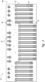
- Fig. 4 is a less schematic top view of a composite structure fabrication system 18 according to the present disclosure
- Fig. 5 is a less schematic profile view of composite structure fabrication system 18.
- system 18 may include a plurality of elongate forming mandrels 32 and a plurality of associated forming machines 50 that may be arranged within a ply assembly area 110.
- forming machines 50 are configured to translate along a length of elongate forming mandrels 32, and this is illustrated in Figs. 4-5 by forming machines 50 being located at differing locations along the length of respective forming mandrels 32.
- system 18 further may include a plurality of ply kitting tools 60 that may be arranged within a ply kitting area 100.
- Ply kitting area 100 also may include a plurality of ply carrier magazines 28.
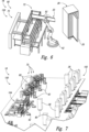
- a ply kitting tool 60 may include a ply kitting robot 62 that may be configured to receive a ply carrier 20 that has one or more ply segments 92 located thereon. Ply kitting robot 62 also may locate ply carriers 20 within a ply carrier magazine 28 for storage and/or staging of ply carriers 20.
- ply kitting tools 60 also may include and/or be associated with a ply segment locating device 70, which may be configured to operatively located ply segments 92 on respective ply carriers 20.
- ply segment locating device 70 may be separate and/or distinct from ply kitting tool 60.
- ply segment locating device 70 may form a portion of ply kitting tool 60 and/or ply kitting robot 62.
- Fig. 7 illustrates more clearly that a plurality of ply carrier magazines 28 may be located and/or staged within ply kitting area 100, or within a ply carrier staging area 102 thereof. This may permit a selected, given, and/or predetermined ply segment 92 to be conveyed to a respective forming machine 50 on a respective elongate forming mandrel 32 (as illustrated in Figs. 4-5 ).
- Fig. 7 also illustrates that ply carrier magazines 28 may include, be operatively attached to, and/or be associated with respective magazine transfer devices 80.
- ply carrier magazines 28 may be located and/or staged within ply carrier staging area 102 of ply kitting area 100 such that a carrier transfer device 40 may receive and/or remove a selected ply carrier 21 from a given ply carrier magazine 28.
- Carrier transfer device 40 then may convey selected ply carrier 21, together with corresponding ply segments 92, from ply carrier staging area 102 of ply kitting area 100 to ply assembly area 110, as illustrated in Fig. 9 .
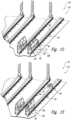
- This may include conveying selected ply carrier 21 in a vertical direction and/or maintaining selected ply carrier 21 in a vertical, or upright, orientation 46 (as illustrated in Fig. 10 ) while it is conveyed.
- carrier transfer device 40 may transition and/or pivot from the vertical, or upright, orientation 46 to a horizontal orientation 48. This may include pivoting at least a portion of carrier transfer device 40 about a pivot structure 42 thereof. As illustrated in Fig. 11 , carrier transfer device 40 then may convey selected ply carrier 21 along a length of an associated elongate forming mandrel 32 and to a selected location 36. This may be accomplished utilizing a carrier transfer robot 44 that may be associated with and/or may form a portion of carrier transfer device 40.
- Forming machine 50 also may move to and/or may be located at selected location 36, and carrier transfer device 40 may transfer selected ply carrier 21 to forming machine 50. This is illustrated in Fig. 12 . Forming machine 50 then may deform selected ply carrier 21 and at least one respective ply segment 92 over a selected portion 38 of an elongate ply forming surface 34 that is defined by elongate forming mandrel 32. Subsequently, and as illustrated in Fig. 13 , carrier transfer device 40 may return selected ply carrier 21 to ply kitting area 100 while the at least one respective ply segment 92 is retained on selected portion 38.
- this process may be repeated any suitable number of times to locate any suitable number of ply segments 92 on elongate ply forming surface 34 such that ply segments 92 generate, create, and/or define a plurality of layered plies 90 that define an uncured composite structure 810.
- This is illustrated in Fig. 14 .
- an uncured composite transfer device 150 then may be utilized to remove a given uncured composite structure 810 from a given elongate forming mandrel 32 and/or to transfer uncured composite structure 810 to a cure mandrel, as discussed in more detail herein.
- Methods 300 may include creating a plurality of ply segments at 305, locating at least one ply segment on each ply carrier of a plurality of ply carriers at 310, storing the plurality of ply carriers within a ply carrier magazine at 315, transferring a plurality of ply carrier magazines at 320, receiving a selected ply carrier from the ply carrier magazine at 325, and/or electronically tracking each ply carrier at 330.
- Methods 300 include conveying the selected ply carrier at 335, translating a forming machine at 340, receiving the selected ply carrier at 345, deforming the selected ply carrier at 350, releasing a respective ply segment at 355, and returning the selected ply carrier at 360. Methods 300 further may include cleaning the selected ply carrier at 365 and include repeating at least a portion of the methods at 370. Methods 300 also may include transferring an uncured composite structure to a cure mandrel at 375 and/or curing the uncured composite structure at 380.
- Creating the plurality of ply segments at 305 may include creating with, or utilizing, a plurality of ply kitting tools.
- the creating at 305 further may include creating a respective ply segment of the plurality of ply segments with each ply kitting tool in the plurality of ply kitting tools. This may include independently creating a different ply segment with each ply kitting tool and/or concurrently creating at least two ply segments with at least two different ply kitting tools.
- the phrase, "creating the plurality of ply segments" or simply the word “creating,” when utilized in the context of the ply segments, may indicate that the ply segments are created, formed, produced, generated, defined, constructed, built, and/or made in any suitable manner.
- the ply segments may be created from a feedstock. This may include cutting the feedstock, severing the feedstock, laying up the feedstock, and/or layering the feedstock.
- the creating at 305 may be accomplished in any suitable manner.
- the creating at 305 may include cutting a respective ply segment from a composite feedstock.
- the creating at 305 may include creating a first ply segment with a first ply kitting tool and concurrently creating a second ply segment with a second ply kitting tool.
- the first ply segment may be different from the second ply segment.
- the first ply segment may have a different boundary, periphery, and/or peripheral shape than the second ply segment.
- the first ply segment may have a different fiber orientation than the second ply segment.
- the first ply segment may be creating from a different material, such as from a different composite feedstock, than the second ply segment.
- Locating at least one ply segment on each ply carrier at 310 may include locating with a ply segment locating device and/or locating with the ply kitting tool, as discussed herein.
- the locating at 310 may include locating any suitable number of ply segments on each ply carrier and/or locating a different ply segment, or a different number of ply segments, on different ply carriers.
- the locating at 310 may include locating a single ply segment on at least one ply carrier.
- the locating at 310 also may include locating a plurality of ply segments on at least one, or a different, ply carrier.
- This may include locating such that the plurality of ply segments defines a plurality of stacked, or layered, ply segments. Additionally or alternatively, this also may include locating such that at least a portion of the plurality of ply segments is spaced apart from a remainder of the plurality of ply segments on a respective ply support surface of the at least one ply carrier. As yet another example, the locating at 310 may include locating such that a first fiber orientation of a first ply segment that is located on the respective ply support surface is different from a second fiber orientation of a second ply segment that is located on the respective ply support surface. It is within the scope of the present disclosure that the locating at 310 further may include vacuum compacting the at least one ply segment on each ply carrier.
- Storing the plurality of ply carriers within the ply carrier magazine at 315 may include storing a respective subset of the plurality of ply carriers within each ply carrier magazine. This may include storing any suitable number of ply carriers in each ply carrier magazine and/or storing a different number of ply carriers in at least one ply carrier magazine when compared to at least one other ply carrier magazine. As examples, the storing at 315 may include storing at least 2, at least 3, at least 4, at least 5, at least 6, at least 8, or at least 10 ply carriers in each of the plurality of ply carrier magazines.
- the ply carriers may include and/or be elongate ply carriers that may have and/or define an elongate axis.
- the storing at 315 may include storing the respective subset of the plurality of ply carriers in an upright, or at least substantially upright, orientation. This may include vertically storing, or arranging, the respective subset of the plurality of ply carriers within each ply carrier magazine. Such a configuration may decrease a floor space requirement of the ply carrier magazines, as discussed herein.
- the storing at 315 additionally or alternatively may include protecting the respective subset of the plurality of ply carriers from an ambient environment that surrounds the ply carrier magazines.
- the storing at 315 may include restricting contact between the respective subset of the plurality of ply carriers and particulate material, such as by sealing the ply carrier magazines and/or by enclosing the respective subset of the plurality of ply carriers within a corresponding ply carrier magazine.
- Transferring the plurality of ply carrier magazines at 320 may include transferring from a kitting tool area to a ply carrier staging area. This may include transferring with a magazine transfer device, examples of which are discussed herein.
- Receiving the selected ply carrier from the ply carrier magazine at 325 may include receiving the selected ply carrier from a respective ply carrier magazine of the plurality of ply carrier magazines and may be performed prior to the conveying at 335.
- the receiving at 325 may include receiving with a carrier transfer device, examples of which are discussed herein.
- Electronically tracking each ply carrier at 330 may include electronically tracking any suitable parameter and/or characteristic of each ply carrier of the plurality of ply carriers.
- the electronically tracking at 330 may include electronically tracking a location of each ply carrier of the plurality of ply carriers.
- the electronically tracking at 330 additionally or alternatively may include electronically tracking a structure of at least one ply segment that is supported by each ply carrier of the plurality of ply carriers.
- the electronically tracking at 330 may include uniquely identifying each ply carrier of the plurality of ply carriers, such as via associating and/or utilizing a unique bar code and/or a unique radio frequency identification tag with each ply carrier.
- the electronically tracking at 330 may include maintaining a database of information, such as of the tracked parameters and/or of the characteristics, for each ply carrier.
- the electronically tracking at 330 may be performed at any suitable time and/or with any suitable sequence during methods 300.
- the electronically tracking at 330 may be performed prior to, during, and/or subsequent to the forming at 305, the locating at 310, the storing at 315, the transferring at 320, the receiving at 325, the conveying at 335, the translating at 340, the receiving at 345, the deforming at 350, the releasing at 355, the returning at 360, the cleaning at 365, and/or the repeating at 370.
- Conveying the selected ply carrier at 335 includes conveying the selected ply carrier with the carrier transfer device. This may include conveying the selected ply carrier from the ply carrier staging area, from a ply kitting area, from the ply kitting area to a ply assembly area, and/or to a selected location along a length of an elongate forming mandrel.
- the elongate forming mandrel defines an elongate ply forming surface that is shaped to define a surface contour of the composite structure.
- the elongate ply forming surface also is configured to receive the plurality of ply segments such that the plurality of ply segments defines a plurality of plies of composite material.
- the plurality of plies of composite material may at least partially produce and/or define the composite structure and/or may define the uncured composite structure.
- the ply carrier magazines may be located within a ply kitting area and/or within a ply carrier staging area of the ply kitting area.
- the elongate forming mandrel may be located in a ply assembly area that is different from, spaced-apart from, and/or at a different elevation than the ply kitting area.
- the ply kitting area may be spaced apart from the ply assembly area in a vertical direction, such as when the ply kitting area is elevated above the ply assembly area or when the ply assembly area is elevated above the ply kitting area.
- the ply kitting area may be at least partially overlapping with the ply assembly area in a horizontal direction.
- the conveying at 335 may include vertically conveying the selected ply carrier from the ply kitting area to the ply assembly area. This may include conveying the selected ply carrier while the selected ply carrier is in the vertical orientation and/or in the horizontal orientation, as discussed herein. This also may include rotating the selected ply carrier to a horizontal orientation prior to conveying the selected ply carrier along the length of the elongate forming mandrel and/or prior to the receiving at 345. In addition, the conveying at 335 also may include horizontally conveying the selected ply carrier along the length of the elongate forming mandrel.
- Translating the forming machine at 340 includes translating the forming machine along the length of the elongate forming mandrel and translating the forming machine to the selected location.
- the translating at 340 may be performed at any suitable time and/or with any suitable sequence during methods 300.
- the translating at 340 may be at least partially concurrent with the conveying at 335, with the electronically tracking at 330, with the receiving at 325, with the transferring at 320, with the storing at 315, with the locating at 310, and/or with the creating at 305.
- Receiving the selected ply carrier at 345 may include receiving the selected ply carrier from the carrier transfer device and/or receiving the selected ply carrier with the forming machine. This may include supporting the selected ply carrier with the forming machine and/or with an end effector of the forming machine.
- Deforming the selected ply carrier at 350 may include deforming the selected ply carrier and a respective ply segment, which is supported by the selected ply carrier, with the forming machine. This may include deforming over a selected portion of the elongate ply forming surface.
- the deforming at 350 may include deforming the selected ply carrier and the respective ply segment in a direction that is transverse to a long, or longitudinal, axis of the ply forming surface. Additionally or alternatively, the deforming at 350 may include locating the respective ply segment between the elongate ply forming surface and the selected ply carrier during the deforming.
- the deforming at 350 further may include compacting the respective ply segment on the elongate ply forming surface.
- the compacting may be performed during the deforming at 350, as part of the deforming at 350, subsequent to the deforming at 350, and/or subsequent to the releasing at 355.
- the compacting may be accomplished in any suitable manner, such as utilizing a compaction device that may form a portion of and/or may be associated with the forming machine.
- the deforming at 350 may be performed at any suitable time and/or with any suitable sequence during methods 300. As examples, the deforming at 350 may be subsequent to the receiving at 345, to the translating at 340, and/or to the conveying at 335. Additionally or alternatively, the deforming at 350 also may be at least partially concurrent with the electronically tracking at 330, with the receiving at 325, with the transferring at 320, with the storing at 315, with the locating at 310, and/or with the creating at 305.
- Releasing the respective ply segment at 355 may include releasing the respective ply segment from the selected ply carrier while retaining the respective ply segment on, in contact with, and/or adhered to the selected portion of the elongate ply forming surface. This may include operatively separating the respective ply segment from the selected ply carrier and/or translating the selected ply carrier away from the respective ply segment.
- Returning the selected ply carrier at 360 includes returning the selected ply carrier to the ply kitting area and may be performed subsequent to the deforming at 350 and/or subsequent to the releasing at 355. This may include transferring the selected ply carrier from the forming machine to the carrier transfer device and/or supporting the selected ply carrier with the carrier transfer device. The returning at 360 further may include returning the selected ply carrier to the respective ply carrier magazine.
- Cleaning the selected ply carrier at 365 may include cleaning to permit and/or facilitate locating another ply segment on the selected ply carrier.
- the selected ply carrier may be re-used a plurality of times during methods 300, such as during the repeating at 370. Under these conditions, it may be desirable to clean and/or condition the ply support surface of the selected ply carrier, such as to decrease a potential for contamination of a ply segment that is supported thereby and/or to increase adhesion between the ply segment and the ply support surface.
- the cleaning at 365 may be accomplished in any suitable manner.
- the cleaning at 365 may include cleaning with, or by sending the selected ply carrier through, a wash station. It is within the scope of the present disclosure that the cleaning at 365 may be performed at any suitable time, with any suitable sequence, and/or with any suitable frequency during methods 300.
- the cleaning at 365 may be performed prior to the locating at 310, prior to each instance of the locating at 310, subsequent to the releasing at 355, subsequent to each instance of the releasing at 355, subsequent to a preselected number of instances of the locating at 310 and/or of the releasing at 355, and/or responsive to detection of greater than a threshold level of contaminants on the ply support surface of the selected ply carrier.
- Repeating at least the portion of the methods at 370 may include repeating any suitable portion of methods 300 with any suitable frequency and/or in any suitable order.
- the repeating at 370 may include repeating at least the conveying at 335, the translating at 340, the receiving at 345, the deforming at 350, the releasing at 355, and the returning at 360 with all or a portion of the plurality of ply carriers.
- Each of the plurality of ply carriers may support a respective ply segment, and the repeating may include repeating to locate the plurality of ply segments on the elongate ply forming surface, thereby at least partially producing the uncured composite structure.
- the repeating at 370 further may include selecting a location within the uncured composite structure for each ply segment and/or selecting a composition of each ply segment.
- a location and/or composition of each ply segment may be electronically tracked, such as via the tracking at 330, and the location of each ply segment may be selected based, at least in part, on the shape and/or composition of the ply segment.
- a specific ply segment may be created, such as during the creating at 305, for each location of a plurality of locations within the uncured composite structure, and the repeating at 370 may include selectively locating each ply segment at a corresponding and/or predetermined location within the uncured composite structure.
- the repeating at 370 additionally or alternatively may include incrementally translating the forming machine along the length of the forming mandrel. This may include incrementally translating the forming machine a first time to locate a first course, layer, or ply of composite material on the elongate ply forming surface and subsequently incrementally translating the forming machine along the length of the forming mandrel a second time to locate a second course, layer, or ply of composite material on the first course of composite material.
- the first course of composite material may include a first subset of the plurality of ply segments and the second course of composite material may include a second, or different, subset of the plurality of ply segments.
- This process may be repeated any suitable number of times to locate and/or build up any suitable number of plies of composite material on the elongate ply forming surface.
- the repeating at 370 may include repeating to retain the plurality of ply segments on a plurality of different selected portions of the elongate ply forming surface.
- Transferring the uncured composite structure to the cure mandrel at 375 may include transferring from the elongate ply forming surface of the elongate forming mandrel to the cure mandrel.
- the transferring at 375 may be accomplished in any suitable manner.
- the transferring at 375 may include transferring with an uncured composite transfer device, examples of which are disclosed herein. It is within the scope of the present disclosure that the transferring at 375 may include transferring a single uncured composite structure to the cure mandrel.
- the transferring at 375 may be repeated to transfer at least one other uncured composite structure, or a plurality of uncured composite structures, to the cure mandrel.
- the plurality of uncured composite structures then may be cured, such as via the curing at 380, to together, or collectively, define the composite structure.
- Curing the uncured composite structure at 380 may include heating the uncured composite structure to cure the uncured composite structure and produce a cured composite structure (i.e., the composite structure). This may include heating with any suitable heating device, examples of which are disclosed herein.
- the curing at 380 may include curing on the cure mandrel.
- the curing at 380 may include curing on the elongate forming mandrel.
- exemplary method 900 may include specification and design 905 of the aircraft 700 and material procurement 910.
- component and subassembly manufacturing 915 and system integration 920 of the aircraft 700 take place.
- the aircraft 700 may go through certification and delivery 925 in order to be placed in service 930.
- routine maintenance and service 935 which also may include modification, reconfiguration, refurbishment, and so on).
- Each of the processes of method 900 may be performed or carried out by a system integrator, a third party, and/or an operator (e.g., a customer).
- a system integrator may include without limitation any number of aircraft manufacturers and major-system subcontractors
- a third party may include without limitation any number of venders, subcontractors, and suppliers
- an operator may be an airline, leasing company, military entity, service organization, and so on.
- aircraft 700 produced by exemplary method 900 may include an airframe 710 with a plurality of systems 712 and an interior 714.
- high-level systems 712 include one or more of a propulsion system 715, an electrical system 716, a hydraulic system 717, and an environmental system 718. Any number of other systems may be included.
- an aerospace example is shown, the principles described herein may be applied to other industries, such as the automotive industry.
- Systems and methods embodied herein may be employed during any one or more of the stages of the manufacturing and service method 900.
- components or subassemblies corresponding to component and subassembly manufacturing process 915 may be fabricated or manufactured in a manner similar to components or subassemblies produced while the aircraft 700 is in service.
- one or more of system embodiments, method embodiments, or a combination thereof may be utilized during the production stages 915 and 920, for example, by substantially expediting assembly of or reducing the cost of an aircraft 700.
- one or more of system embodiments, method embodiments, or a combination thereof may be utilized while the aircraft 700 is in service, for example and without limitation, to maintenance and service 935.
- the terms “adapted” and “configured” mean that the element, component, or other subject matter is designed and/or intended to perform a given function. Thus, the use of the terms “adapted” and “configured” should not be construed to mean that a given element, component, or other subject matter is simply “capable of” performing a given function but that the element, component, and/or other subject matter is specifically selected, created, implemented, utilized, programmed, and/or designed for the purpose of performing the function. It is also within the scope of the present disclosure that elements, components, and/or other recited subject matter that is recited as being adapted to perform a particular function may additionally or alternatively be described as being configured to perform that function, and vice versa. Similarly, subject matter that is recited as being configured to perform a particular function may additionally or alternatively be described as being operative to perform that function.
- the phrase, "for example,” the phrase, “as an example,” and/or simply the term “example,” when used with reference to one or more components, features, details, structures, embodiments, and/or methods according to the present disclosure, are intended to convey that the described component, feature, detail, structure, embodiment, and/or method is an illustrative, non-exclusive example of components, features, details, structures, embodiments, and/or methods according to the present disclosure.
Landscapes
- Engineering & Computer Science (AREA)
- Mechanical Engineering (AREA)
- Chemical & Material Sciences (AREA)
- Composite Materials (AREA)
- Robotics (AREA)
- Moulding By Coating Moulds (AREA)
Claims (15)
- System zur Herstellung von Verbundwerkstoffstrukturen (18), umfassend:eine Mehrzahl von Lagenträgern (20), wobei jeder Lagenträger (20) der Mehrzahl von Lagenträgern (20) eine Lagenträgerfläche (22) definiert, die konfiguriert ist, um vorübergehend mindestens ein Lagensegment (92) zu tragen;einen langgestreckten Formungsdorn (32), der eine langgestreckte Lagenformungsfläche (34) definiert, wobei die langgestreckte Lagenformungsfläche (34) geformt ist, um eine Oberflächenkontur einer Verbundstruktur (800) zu definieren, und konfiguriert ist, um eine Mehrzahl von Lagensegmenten (92) aufzunehmen, um eine Mehrzahl von Lagen aus Verbundmaterial (90) zu definieren, das zumindest teilweise die Verbundstruktur (800) definiert;eine Trägertransfervorrichtung (40), die konfiguriert ist, um selektiv einen ausgewählten Lagenträger (21) aus der Mehrzahl von Lagenträgern (20) von einem Lagenzusammenstellungsbereich (100) zu einer Zwischenposition (180) zu befördern und den ausgewählten Lagenträger (21) zu dem Lagenzusammenstellungsbereich (100) zurückzufördern; undeine Formmaschine (50), die konfiguriert ist, um den ausgewählten Lagenträger (21) an der Zwischenposition (180) aufzunehmen, wobei die Formmaschine (50) eine automatisierte Formmaschine (50) ist, die eine Formmaschinenverschiebungsvorrichtung (54) enthält, die konfiguriert ist, um die Formmaschine (50) selektiv zu einer ausgewählten Position (36) entlang einer Länge des langgestreckten Formungsdorns (32) zu verschieben, wobei die Formmaschine (50) ferner konfiguriert ist, um den ausgewählten Lagenträger (21) und ein jeweiliges Lagensegment (92) über einem ausgewählten Abschnitt (38) der langgestreckten Lagenformungsfläche zu verformen und den ausgewählten Lagenträger (21) von dem jeweiligen Lagensegment (92) zu trennen, so dass das jeweilige Lagensegment (92) von dem ausgewählten Abschnitt (38) der langgestreckten Lagenformungsfläche getragen wird.
- System (18) nach Anspruch 1, wobei das System (18) ferner eine Mehrzahl von automatisiertenLagenzusammenstellungswerkzeugen (60) umfasst, die konfiguriert sind, um die Mehrzahl von Lagensegmenten (92) zu erzeugen, wobei jedes Lagenzusammenstellungswerkzeug (60) der Mehrzahl von automatisiertenLagenzusammenstellungswerkzeugen (60) konfiguriert ist, um jeweils ein Lagensegment (92) der Mehrzahl von Lagensegmenten (92) zu erzeugen und um unabhängig von einem Rest der Mehrzahl von automatisiertenLagenzusammenstellungswerkzeugen (60) zu arbeiten.
- System (18) nach Anspruch 1 oder 2, wobei das System (18) ferner eine automatische Lagensegment-Lokalisierungsvorrichtung (70) umfasst, die konfiguriert ist, um das mindestens eine Lagensegment (92) auf jedem Lagenträger (20) der Mehrzahl von Lagenträgern (20) zu lokalisieren.
- System (18) nach einem der Ansprüche 1, 2 oder 3, wobei das System (18) ferner eine Mehrzahl von Lagenträgermagazinen (28) umfasst, wobei jedes Lagenträgermagazin (28) der Mehrzahl von Lagenträgermagazinen (28) konfiguriert ist, um jeweils eine Teilmenge der Mehrzahl von Lagenträgern (20) aufzunehmen.
- System (18) nach Anspruch 4, wobei das System ferner eine automatische Magazintransfervorrichtung (80) umfasst, die konfiguriert ist, um die Mehrzahl von Lagenträgermagazinen (28) selektiv innerhalb des Lagenzusammenstellungsbereichs (100) und von einem Zusammenstellungswerkzeugbereich (104) zu einem Lagenträgerbereitstellungsbereich (102) zu befördern.
- System (18) nach einem der Ansprüche 1 bis 5, bei dem die Trägertransfervorrichtung (40) eine automatische Trägertransfervorrichtung ist.
- System (18) nach einem der Ansprüche 1 bis 6, bei dem die Trägertransfervorrichtung (40) konfiguriert ist, um den ausgewählten Lagenträger (21) aus einem jeweiligen Lagenträgermagazin (28) zu entfernen.
- System (18) nach Anspruch 7, bei dem sich das jeweilige Lagenträger-Magazin (28) im Lagenzusammenstellungsbereich (100) und der langgestreckte Formungsdorn (32) in einem Lagenmontagebereich (110) befindet, und bei dem ferner die Trägertransfervorrichtung (40) konfiguriert ist, um den ausgewählten Lagenträger (21) aus dem Lagenzusammenstellungsbereich (100) zum Lagenmontagebereich (110) zu befördern.
- System (18) nach einem der Ansprüche 1 bis 8, bei dem die Trägertransfervorrichtung (40) konfiguriert ist, um selektiv und sequentiell eine Mehrzahl von ausgewählten Lagenträgern (21) aus der Mehrzahl von Lagenträgern (20) zu der Zwischenposition (180) zu befördern, und bei dem ferner die Formmaschine (50) konfiguriert ist, um selektiv und sequentiell jeden aus der Mehrzahl von ausgewählten Lagenträgern (21) aufzunehmen und jeden aus der Mehrzahl von ausgewählten Lagenträgern (21) an jeweiligen Stellen entlang der Länge des langgestreckten Formungsdorns (32) zu verformen.
- Verfahren (300) zum Herstellen einer Verbundstruktur (800), wobei das Verfahren (300) umfasst:Fördern (335) eines ausgewählten Lagenträgers (21) von einem Lagenzusammenstellungsbereich (100) zu einer ausgewählten Position (36) entlang einer Länge eines langgestreckten Formungsdorns (32), der eine langgestreckte Lagenformungsfläche (34) definiert, wobei die langgestreckte Lagenformungsfläche (34) geformt ist, um eine Oberflächenkontur einer Verbundstruktur (800) zu definieren, und konfiguriert ist, um eine Mehrzahl von Lagensegmenten (92) aufzunehmen, um eine Mehrzahl von Lagen aus Verbundmaterial (90) zu definieren, die zumindest teilweise die Verbundstruktur (800) definiert;Verschieben (340) einer Formmaschine (50) entlang der Länge des langgestreckten Formdorns (32) zu der ausgewählten Stelle (36);Aufnehmen (345) des ausgewählten Lagenträgers (21) mit der Formmaschine (50);Umformen (350) des ausgewählten Lagenträgers (21) und eines jeweils von dem ausgewählten Lagenträger (21) getragenen Lagensegments (92) mit der Formmaschine (50) über einem ausgewählten Abschnitt (38) der langgestreckten Lagenformungsfläche;Freigeben (355) des jeweiligen Lagensegments (92) von dem ausgewählten Lagenträger (21), während das jeweilige Lagensegment (92) auf dem ausgewählten Abschnitt (38) der langgestreckten Lagenformungsfläche gehalten wird;Zurückfördern (360) des ausgewählten Lagenträgers (21) in den Lagenzusammenstellungsbereich (100); undWiederholen (370) des Förderns (335), des Verschiebens (340), des Aufnehmens (345), des Umformens (350), des Freigebens (355) und des Zurückförderns (360) mit einer Mehrzahl von Lagenträgern (20), die jedes jeweils ein Lagensegment (92) tragen, um die Mehrzahl von Lagensegmenten (92) auf der langgestreckten Lagenformungsfläche (34) anzuordnen und zumindest teilweise eine ungehärtete Verbundstruktur (810) zu definieren.
- Verfahren (300) nach Anspruch 10, wobei das Verfahren (300) ferner das Erzeugen (305) der Mehrzahl von Lagensegmenten (92) umfasst, wobei das Erzeugen (305) das unabhängige Erzeugen jeweils eines Lagensegments (92) der Mehrzahl von Lagensegmenten (92) mit jedem Lagenzusammenstellungswerkzeug (60) einer Mehrzahl von automatischen Lagenzusammenstellungswerkzeugen (60) umfasst.
- Verfahren (300) nach Anspruch 10 oder 11, wobei das Verfahren (300) ferner das Lagern (315) jeweils einer Teilmenge der Mehrzahl von Lagenträgern (20) in jedem einer Mehrzahl von Lagenträgermagazinen (28) umfasst.
- Verfahren (300) nach einem der Ansprüche 10, 11 oder 12, wobei das Verfahren (300) das Anordnen des jeweiligen Lagensegments (92) zwischen der langgestreckten Lagenformungsfläche (34) und dem ausgewählten Lagenträger (20) während des Umformens (350) umfasst.
- Verfahren (300) nach einem der Ansprüche 10 bis 13, bei dem das Wiederholen (370) das Auswählen sowohl einer Position innerhalb der ungehärteten Verbundstruktur (810) für jedes Lagensegment (92) der Mehrzahl von Lagensegmenten (92) als auch einer Zusammensetzung jedes Lagensegments (92) der Mehrzahl von Lagensegmenten (92) umfasst.
- Verfahren (300) nach einem der Ansprüche 10 bis 14, bei dem das Wiederholen (370) ein erstes schrittweises Verschieben der Formmaschine (50) entlang der Länge des langgestreckten Formdorns (32), um eine erste Schicht von Verbundmaterial auf der langgestreckten Lagenformungsfläche (34) zu positionieren, und anschließend ein zweites schrittweises Verschieben der Formmaschine (50) entlang der Länge des langgestreckten Formdorns (32), um eine zweite Schicht von Verbundmaterial auf der ersten Schicht von Verbundmaterial zu positionieren, umfasst,
wobei die erste Schicht des Verbundmaterials eine erste Teilmenge der Mehrzahl von Schichtsegmenten (92) umfasst, und wobei ferner die zweite Schicht des Verbundmaterials eine zweite Teilmenge der Mehrzahl von Schichtsegmenten (92) umfasst.
Applications Claiming Priority (1)
| Application Number | Priority Date | Filing Date | Title |
|---|---|---|---|
| US14/740,493 US10800111B2 (en) | 2015-06-16 | 2015-06-16 | Composite structure fabrication systems and methods |
Publications (2)
| Publication Number | Publication Date |
|---|---|
| EP3106280A1 EP3106280A1 (de) | 2016-12-21 |
| EP3106280B1 true EP3106280B1 (de) | 2023-10-04 |
Family
ID=56131428
Family Applications (1)
| Application Number | Title | Priority Date | Filing Date |
|---|---|---|---|
| EP16174447.9A Active EP3106280B1 (de) | 2015-06-16 | 2016-06-14 | Verbundstrukturherstellungssysteme und -verfahren |
Country Status (4)
| Country | Link |
|---|---|
| US (2) | US10800111B2 (de) |
| EP (1) | EP3106280B1 (de) |
| JP (1) | JP6867757B2 (de) |
| CN (1) | CN106256538B (de) |
Families Citing this family (29)
| Publication number | Priority date | Publication date | Assignee | Title |
|---|---|---|---|---|
| WO2015094059A1 (en) * | 2013-12-20 | 2015-06-25 | Saab Ab | Stiffening element and reinforced structure |
| US10456960B2 (en) | 2015-07-24 | 2019-10-29 | The Boeing Company | Systems and methods for incrementally forming a composite part |
| US10906210B2 (en) * | 2017-01-25 | 2021-02-02 | The Boeing Company | Mandrel for composite part fabrication and repair |
| US10974850B2 (en) * | 2017-11-02 | 2021-04-13 | The Boeing Company | Systems and methods for in situ manufacturing of minimally tooled stringers |
| US10843449B2 (en) | 2017-12-14 | 2020-11-24 | The Boeing Company | Method and apparatus for forming composite plies on contoured tool surfaces |
| US11247413B2 (en) * | 2018-12-17 | 2022-02-15 | The Boeing Company | Composite parts including hybrid plies, methods of forming the composite parts, and systems for forming the composite parts |
| NL2023372B1 (en) * | 2019-06-25 | 2021-02-01 | Airborne Int B V | Preforming system and method |
| US11655018B2 (en) * | 2019-07-24 | 2023-05-23 | The Boeing Company | Permeable radius filler for composite structure |
| JP7656484B2 (ja) * | 2020-06-23 | 2025-04-03 | ザ・ボーイング・カンパニー | プライバイプライ式製造プロセスにおいてラミネートプライの被トリミング部分を選択的に除去するための自動除去装置、システム、及び方法 |
| AT523964B1 (de) * | 2020-07-08 | 2023-05-15 | Gfm Gmbh | Verfahren zum Bereitstellen von Zuschnitten aus einer Faserbahn |
| EP3967480B1 (de) * | 2020-09-15 | 2025-12-10 | The Boeing Company | Systeme und verfahren zur formung von verbundelementen |
| NL2027396B1 (en) * | 2021-01-26 | 2022-08-12 | Boeing Co | Composite wing panels and fabrication method |
| ES2991027T3 (es) | 2020-11-18 | 2024-12-02 | Boeing Co | Paneles de ala de material compuesto y método de fabricación |
| US12077319B2 (en) * | 2020-11-18 | 2024-09-03 | The Boeing Company | Fabrication line, systems, and methods for fuselage sections |
| US12097973B2 (en) | 2020-11-18 | 2024-09-24 | The Boeing Company | Composite wing panels and fabrication method |
| EP4000842B1 (de) | 2020-11-18 | 2025-01-01 | The Boeing Company | Verbundvorformanordnungsverfahren und -vorrichtung |
| US12195201B2 (en) | 2020-11-18 | 2025-01-14 | The Boeing Company | Composite preform assembly method and apparatus |
| NL2027397B1 (en) * | 2021-01-26 | 2022-08-17 | Boeing Co | Composite preform assembly method and apparatus |
| US11685128B2 (en) | 2020-12-07 | 2023-06-27 | The Boeing Company | System and method for fabricating a composite structure |
| US12194693B2 (en) * | 2020-12-07 | 2025-01-14 | The Boeing Company | Forming apparatus, method, and system |
| US11964442B2 (en) | 2020-12-07 | 2024-04-23 | The Boeing Company | Forming apparatus, method, and system |
| US11654641B2 (en) | 2020-12-07 | 2023-05-23 | The Boeing Company | Composite ply placement system and method |
| US11826970B2 (en) | 2020-12-07 | 2023-11-28 | The Boeing Company | Forming apparatus, method, and system |
| US11999116B2 (en) | 2021-08-30 | 2024-06-04 | The Boeing Company | Composite forming apparatus, system and method |
| US11897209B2 (en) | 2021-08-30 | 2024-02-13 | The Boeing Company | Composite forming apparatus, system and method |
| US12138864B2 (en) | 2021-08-30 | 2024-11-12 | The Boeing Company | Forming apparatus, methods, and systems |
| US12103249B2 (en) | 2021-08-30 | 2024-10-01 | The Boeing Company | Composite forming apparatus, methods, and systems |
| US20230249416A1 (en) * | 2022-02-04 | 2023-08-10 | Northrop Grumman Systems Corporation | Automated methods for manufacturing sheets of composite material and composite structures, pattern preparation and forming systems, and sheets of composite material |
| EP4249222A1 (de) | 2022-03-23 | 2023-09-27 | Siemens Gamesa Renewable Energy A/S | Materiallegevorrichtung und verfahren zum produzieren von windturbinenblättern unter verwendung von faserschichten |
Family Cites Families (21)
| Publication number | Priority date | Publication date | Assignee | Title |
|---|---|---|---|---|
| DE3003552C2 (de) * | 1980-01-31 | 1982-06-24 | Messerschmitt-Bölkow-Blohm GmbH, 8000 München | Flächenbauteil, insbesondere für ein Luftfahrzeug |
| US4475976A (en) | 1983-12-23 | 1984-10-09 | The Boeing Company | Method and apparatus for forming composite material articles |
| US5209804A (en) * | 1991-04-30 | 1993-05-11 | United Technologies Corporation | Integrated, automted composite material manufacturing system for pre-cure processing of preimpregnated composite materials |
| FR2693146B1 (fr) | 1992-07-02 | 1994-08-19 | Snecma | Installation pour la fabrication par drapage de structures multicouches en matériaux composites. |
| US6814916B2 (en) | 2002-08-30 | 2004-11-09 | The Boeing Company | Forming method for composites |
| US7137182B2 (en) * | 2002-11-22 | 2006-11-21 | The Boeing Company | Parallel configuration composite material fabricator |
| US7228611B2 (en) * | 2003-11-18 | 2007-06-12 | The Boeing Company | Method of transferring large uncured composite laminates |
| US7879177B2 (en) | 2006-11-20 | 2011-02-01 | The Boeing Company | Apparatus and method for composite material trim-on-the-fly |
| US9770871B2 (en) | 2007-05-22 | 2017-09-26 | The Boeing Company | Method and apparatus for layup placement |
| US8568551B2 (en) | 2007-05-22 | 2013-10-29 | The Boeing Company | Pre-patterned layup kit and method of manufacture |
| US8936695B2 (en) | 2007-07-28 | 2015-01-20 | The Boeing Company | Method for forming and applying composite layups having complex geometries |
| US8752293B2 (en) | 2007-12-07 | 2014-06-17 | The Boeing Company | Method of fabricating structures using composite modules and structures made thereby |
| US8916010B2 (en) | 2007-12-07 | 2014-12-23 | The Boeing Company | Composite manufacturing method |
| US9387657B2 (en) | 2010-11-12 | 2016-07-12 | The Boeing Company | Method of fabricating a curved composite structure using composite prepreg tape |
| US8551380B2 (en) | 2010-11-12 | 2013-10-08 | The Boeing Company | Method of laying up prepreg plies on contoured tools using a deformable carrier film |
| US9314974B2 (en) | 2013-01-07 | 2016-04-19 | The Boeing Company | Method and apparatus for fabricating contoured laminate structures |
| MX371351B (es) | 2013-01-07 | 2020-01-27 | Boeing Co | Metodo de fabricacion de estructura compuesta curveada utilizando cinta compuesta de prepeg. |
| US20160009051A1 (en) | 2013-01-30 | 2016-01-14 | The Boeing Company | Veil-stabilized Composite with Improved Tensile Strength |
| JP5873887B2 (ja) * | 2013-05-15 | 2016-03-01 | 東芝機械株式会社 | 成形品製造装置及び成形品の製造方法 |
| DE102013105080B4 (de) | 2013-05-17 | 2016-06-23 | Thyssenkrupp Steel Europe Ag | Verfahren zur Herstellung von Halbzeugen oder Bauteilen aus faserverstärktem thermoplastischen Kunststoff, nach dem Verfahren hergestelltes Halbzeug und daraus hergestelltes Bauteil |
| US9761939B2 (en) | 2015-08-17 | 2017-09-12 | The Boeing Company | Integrated low profile phased array antenna system |
-
2015
- 2015-06-16 US US14/740,493 patent/US10800111B2/en active Active
-
2016
- 2016-06-14 JP JP2016117925A patent/JP6867757B2/ja active Active
- 2016-06-14 EP EP16174447.9A patent/EP3106280B1/de active Active
- 2016-06-14 CN CN201610414094.6A patent/CN106256538B/zh active Active
-
2020
- 2020-08-12 US US16/991,933 patent/US11117332B2/en active Active
Also Published As
| Publication number | Publication date |
|---|---|
| US20160368226A1 (en) | 2016-12-22 |
| JP2017061133A (ja) | 2017-03-30 |
| US20200368977A1 (en) | 2020-11-26 |
| US11117332B2 (en) | 2021-09-14 |
| EP3106280A1 (de) | 2016-12-21 |
| US10800111B2 (en) | 2020-10-13 |
| CN106256538A (zh) | 2016-12-28 |
| CN106256538B (zh) | 2020-09-01 |
| JP6867757B2 (ja) | 2021-05-12 |
Similar Documents
| Publication | Publication Date | Title |
|---|---|---|
| EP3106280B1 (de) | Verbundstrukturherstellungssysteme und -verfahren | |
| US8728262B2 (en) | Rapid fabrication of a composite part | |
| US8844108B2 (en) | Large area repair of composite aircraft | |
| EP2067611B1 (de) | Herstellungsverfahren von Modularverbundstoff | |
| EP2731784B1 (de) | Zelle mit reinen und schmutzigen abschnitten zur herstellung von verbundteilen | |
| US11072157B2 (en) | Method and apparatus for forming contoured stiffeners | |
| CN109747861B (zh) | 用于现场制造最低限度地用工具加工的桁条的系统和方法 | |
| US12077319B2 (en) | Fabrication line, systems, and methods for fuselage sections | |
| EP4008533B1 (de) | System und verfahren zur herstellung einer verbundstruktur | |
| US9545758B2 (en) | Two piece mandrel manufacturing system | |
| Sarhadi | Robotic handling and lay-up of advanced composite materials—an overview | |
| EP4000845B1 (de) | Fertigungssysteme und verfahren für rumpfabschnitte | |
| EP4000847B1 (de) | Fertigungssysteme für rumpfabschnitte | |
| US12151831B2 (en) | Fabrication of curved composite preforms for aircraft via assembly lines | |
| EP4000846B1 (de) | Fertigungsstrasse und systeme für rumpfabschnitte | |
| EP4000880B1 (de) | Herstellung von gekrümmten verbundmaterialvorformen für flugzeuge über montagelinien | |
| NL2027437B1 (en) | Fabrication of curved composite preforms for aircraft via assembly lines | |
| HANDLING | School of Engineering and Applied Science | |
| HK1164221A (en) | Composite manufacturing method using an assembly of composite modules |
Legal Events
| Date | Code | Title | Description |
|---|---|---|---|
| PUAI | Public reference made under article 153(3) epc to a published international application that has entered the european phase |
Free format text: ORIGINAL CODE: 0009012 |
|
| STAA | Information on the status of an ep patent application or granted ep patent |
Free format text: STATUS: REQUEST FOR EXAMINATION WAS MADE |
|
| 17P | Request for examination filed |
Effective date: 20160614 |
|
| AK | Designated contracting states |
Kind code of ref document: A1 Designated state(s): AL AT BE BG CH CY CZ DE DK EE ES FI FR GB GR HR HU IE IS IT LI LT LU LV MC MK MT NL NO PL PT RO RS SE SI SK SM TR |
|
| AX | Request for extension of the european patent |
Extension state: BA ME |
|
| STAA | Information on the status of an ep patent application or granted ep patent |
Free format text: STATUS: EXAMINATION IS IN PROGRESS |
|
| 17Q | First examination report despatched |
Effective date: 20201209 |
|
| GRAP | Despatch of communication of intention to grant a patent |
Free format text: ORIGINAL CODE: EPIDOSNIGR1 |
|
| STAA | Information on the status of an ep patent application or granted ep patent |
Free format text: STATUS: GRANT OF PATENT IS INTENDED |
|
| RIC1 | Information provided on ipc code assigned before grant |
Ipc: B29L 31/30 20060101ALN20221117BHEP Ipc: B29C 70/30 20060101ALI20221117BHEP Ipc: B29C 70/38 20060101ALI20221117BHEP Ipc: B29C 31/08 20060101AFI20221117BHEP |
|
| INTG | Intention to grant announced |
Effective date: 20221212 |
|
| RAP3 | Party data changed (applicant data changed or rights of an application transferred) |
Owner name: THE BOEING COMPANY |
|
| GRAJ | Information related to disapproval of communication of intention to grant by the applicant or resumption of examination proceedings by the epo deleted |
Free format text: ORIGINAL CODE: EPIDOSDIGR1 |
|
| STAA | Information on the status of an ep patent application or granted ep patent |
Free format text: STATUS: EXAMINATION IS IN PROGRESS |
|
| GRAP | Despatch of communication of intention to grant a patent |
Free format text: ORIGINAL CODE: EPIDOSNIGR1 |
|
| STAA | Information on the status of an ep patent application or granted ep patent |
Free format text: STATUS: GRANT OF PATENT IS INTENDED |
|
| INTC | Intention to grant announced (deleted) | ||
| RIC1 | Information provided on ipc code assigned before grant |
Ipc: B29L 31/30 20060101ALN20230413BHEP Ipc: B29C 70/30 20060101ALI20230413BHEP Ipc: B29C 70/38 20060101ALI20230413BHEP Ipc: B29C 31/08 20060101AFI20230413BHEP |
|
| INTG | Intention to grant announced |
Effective date: 20230428 |
|
| P01 | Opt-out of the competence of the unified patent court (upc) registered |
Effective date: 20230612 |
|
| GRAS | Grant fee paid |
Free format text: ORIGINAL CODE: EPIDOSNIGR3 |
|
| GRAA | (expected) grant |
Free format text: ORIGINAL CODE: 0009210 |
|
| STAA | Information on the status of an ep patent application or granted ep patent |
Free format text: STATUS: THE PATENT HAS BEEN GRANTED |
|
| AK | Designated contracting states |
Kind code of ref document: B1 Designated state(s): AL AT BE BG CH CY CZ DE DK EE ES FI FR GB GR HR HU IE IS IT LI LT LU LV MC MK MT NL NO PL PT RO RS SE SI SK SM TR |
|
| REG | Reference to a national code |
Ref country code: GB Ref legal event code: FG4D |
|
| REG | Reference to a national code |
Ref country code: CH Ref legal event code: EP |
|
| REG | Reference to a national code |
Ref country code: IE Ref legal event code: FG4D |
|
| REG | Reference to a national code |
Ref country code: DE Ref legal event code: R096 Ref document number: 602016083133 Country of ref document: DE |
|
| REG | Reference to a national code |
Ref country code: LT Ref legal event code: MG9D |
|
| REG | Reference to a national code |
Ref country code: NL Ref legal event code: MP Effective date: 20231004 |
|
| REG | Reference to a national code |
Ref country code: AT Ref legal event code: MK05 Ref document number: 1617291 Country of ref document: AT Kind code of ref document: T Effective date: 20231004 |
|
| PG25 | Lapsed in a contracting state [announced via postgrant information from national office to epo] |
Ref country code: NL Free format text: LAPSE BECAUSE OF FAILURE TO SUBMIT A TRANSLATION OF THE DESCRIPTION OR TO PAY THE FEE WITHIN THE PRESCRIBED TIME-LIMIT Effective date: 20231004 |
|
| PG25 | Lapsed in a contracting state [announced via postgrant information from national office to epo] |
Ref country code: GR Free format text: LAPSE BECAUSE OF FAILURE TO SUBMIT A TRANSLATION OF THE DESCRIPTION OR TO PAY THE FEE WITHIN THE PRESCRIBED TIME-LIMIT Effective date: 20240105 |
|
| PG25 | Lapsed in a contracting state [announced via postgrant information from national office to epo] |
Ref country code: IS Free format text: LAPSE BECAUSE OF FAILURE TO SUBMIT A TRANSLATION OF THE DESCRIPTION OR TO PAY THE FEE WITHIN THE PRESCRIBED TIME-LIMIT Effective date: 20240204 |
|
| PG25 | Lapsed in a contracting state [announced via postgrant information from national office to epo] |
Ref country code: LT Free format text: LAPSE BECAUSE OF FAILURE TO SUBMIT A TRANSLATION OF THE DESCRIPTION OR TO PAY THE FEE WITHIN THE PRESCRIBED TIME-LIMIT Effective date: 20231004 |
|
| PG25 | Lapsed in a contracting state [announced via postgrant information from national office to epo] |
Ref country code: AT Free format text: LAPSE BECAUSE OF FAILURE TO SUBMIT A TRANSLATION OF THE DESCRIPTION OR TO PAY THE FEE WITHIN THE PRESCRIBED TIME-LIMIT Effective date: 20231004 |
|
| PG25 | Lapsed in a contracting state [announced via postgrant information from national office to epo] |
Ref country code: ES Free format text: LAPSE BECAUSE OF FAILURE TO SUBMIT A TRANSLATION OF THE DESCRIPTION OR TO PAY THE FEE WITHIN THE PRESCRIBED TIME-LIMIT Effective date: 20231004 |
|
| PG25 | Lapsed in a contracting state [announced via postgrant information from national office to epo] |
Ref country code: LT Free format text: LAPSE BECAUSE OF FAILURE TO SUBMIT A TRANSLATION OF THE DESCRIPTION OR TO PAY THE FEE WITHIN THE PRESCRIBED TIME-LIMIT Effective date: 20231004 Ref country code: IS Free format text: LAPSE BECAUSE OF FAILURE TO SUBMIT A TRANSLATION OF THE DESCRIPTION OR TO PAY THE FEE WITHIN THE PRESCRIBED TIME-LIMIT Effective date: 20240204 Ref country code: GR Free format text: LAPSE BECAUSE OF FAILURE TO SUBMIT A TRANSLATION OF THE DESCRIPTION OR TO PAY THE FEE WITHIN THE PRESCRIBED TIME-LIMIT Effective date: 20240105 Ref country code: ES Free format text: LAPSE BECAUSE OF FAILURE TO SUBMIT A TRANSLATION OF THE DESCRIPTION OR TO PAY THE FEE WITHIN THE PRESCRIBED TIME-LIMIT Effective date: 20231004 Ref country code: BG Free format text: LAPSE BECAUSE OF FAILURE TO SUBMIT A TRANSLATION OF THE DESCRIPTION OR TO PAY THE FEE WITHIN THE PRESCRIBED TIME-LIMIT Effective date: 20240104 Ref country code: AT Free format text: LAPSE BECAUSE OF FAILURE TO SUBMIT A TRANSLATION OF THE DESCRIPTION OR TO PAY THE FEE WITHIN THE PRESCRIBED TIME-LIMIT Effective date: 20231004 Ref country code: PT Free format text: LAPSE BECAUSE OF FAILURE TO SUBMIT A TRANSLATION OF THE DESCRIPTION OR TO PAY THE FEE WITHIN THE PRESCRIBED TIME-LIMIT Effective date: 20240205 |
|
| PG25 | Lapsed in a contracting state [announced via postgrant information from national office to epo] |
Ref country code: SE Free format text: LAPSE BECAUSE OF FAILURE TO SUBMIT A TRANSLATION OF THE DESCRIPTION OR TO PAY THE FEE WITHIN THE PRESCRIBED TIME-LIMIT Effective date: 20231004 Ref country code: RS Free format text: LAPSE BECAUSE OF FAILURE TO SUBMIT A TRANSLATION OF THE DESCRIPTION OR TO PAY THE FEE WITHIN THE PRESCRIBED TIME-LIMIT Effective date: 20231004 Ref country code: PL Free format text: LAPSE BECAUSE OF FAILURE TO SUBMIT A TRANSLATION OF THE DESCRIPTION OR TO PAY THE FEE WITHIN THE PRESCRIBED TIME-LIMIT Effective date: 20231004 Ref country code: NO Free format text: LAPSE BECAUSE OF FAILURE TO SUBMIT A TRANSLATION OF THE DESCRIPTION OR TO PAY THE FEE WITHIN THE PRESCRIBED TIME-LIMIT Effective date: 20240104 Ref country code: LV Free format text: LAPSE BECAUSE OF FAILURE TO SUBMIT A TRANSLATION OF THE DESCRIPTION OR TO PAY THE FEE WITHIN THE PRESCRIBED TIME-LIMIT Effective date: 20231004 Ref country code: HR Free format text: LAPSE BECAUSE OF FAILURE TO SUBMIT A TRANSLATION OF THE DESCRIPTION OR TO PAY THE FEE WITHIN THE PRESCRIBED TIME-LIMIT Effective date: 20231004 |
|
| REG | Reference to a national code |
Ref country code: DE Ref legal event code: R097 Ref document number: 602016083133 Country of ref document: DE |
|
| PG25 | Lapsed in a contracting state [announced via postgrant information from national office to epo] |
Ref country code: DK Free format text: LAPSE BECAUSE OF FAILURE TO SUBMIT A TRANSLATION OF THE DESCRIPTION OR TO PAY THE FEE WITHIN THE PRESCRIBED TIME-LIMIT Effective date: 20231004 |
|
| PG25 | Lapsed in a contracting state [announced via postgrant information from national office to epo] |
Ref country code: CZ Free format text: LAPSE BECAUSE OF FAILURE TO SUBMIT A TRANSLATION OF THE DESCRIPTION OR TO PAY THE FEE WITHIN THE PRESCRIBED TIME-LIMIT Effective date: 20231004 |
|
| PG25 | Lapsed in a contracting state [announced via postgrant information from national office to epo] |
Ref country code: SK Free format text: LAPSE BECAUSE OF FAILURE TO SUBMIT A TRANSLATION OF THE DESCRIPTION OR TO PAY THE FEE WITHIN THE PRESCRIBED TIME-LIMIT Effective date: 20231004 |
|
| PG25 | Lapsed in a contracting state [announced via postgrant information from national office to epo] |
Ref country code: SM Free format text: LAPSE BECAUSE OF FAILURE TO SUBMIT A TRANSLATION OF THE DESCRIPTION OR TO PAY THE FEE WITHIN THE PRESCRIBED TIME-LIMIT Effective date: 20231004 Ref country code: SK Free format text: LAPSE BECAUSE OF FAILURE TO SUBMIT A TRANSLATION OF THE DESCRIPTION OR TO PAY THE FEE WITHIN THE PRESCRIBED TIME-LIMIT Effective date: 20231004 Ref country code: RO Free format text: LAPSE BECAUSE OF FAILURE TO SUBMIT A TRANSLATION OF THE DESCRIPTION OR TO PAY THE FEE WITHIN THE PRESCRIBED TIME-LIMIT Effective date: 20231004 Ref country code: IT Free format text: LAPSE BECAUSE OF FAILURE TO SUBMIT A TRANSLATION OF THE DESCRIPTION OR TO PAY THE FEE WITHIN THE PRESCRIBED TIME-LIMIT Effective date: 20231004 Ref country code: EE Free format text: LAPSE BECAUSE OF FAILURE TO SUBMIT A TRANSLATION OF THE DESCRIPTION OR TO PAY THE FEE WITHIN THE PRESCRIBED TIME-LIMIT Effective date: 20231004 Ref country code: DK Free format text: LAPSE BECAUSE OF FAILURE TO SUBMIT A TRANSLATION OF THE DESCRIPTION OR TO PAY THE FEE WITHIN THE PRESCRIBED TIME-LIMIT Effective date: 20231004 Ref country code: CZ Free format text: LAPSE BECAUSE OF FAILURE TO SUBMIT A TRANSLATION OF THE DESCRIPTION OR TO PAY THE FEE WITHIN THE PRESCRIBED TIME-LIMIT Effective date: 20231004 |
|
| PLBE | No opposition filed within time limit |
Free format text: ORIGINAL CODE: 0009261 |
|
| STAA | Information on the status of an ep patent application or granted ep patent |
Free format text: STATUS: NO OPPOSITION FILED WITHIN TIME LIMIT |
|
| 26N | No opposition filed |
Effective date: 20240705 |
|
| PG25 | Lapsed in a contracting state [announced via postgrant information from national office to epo] |
Ref country code: SI Free format text: LAPSE BECAUSE OF FAILURE TO SUBMIT A TRANSLATION OF THE DESCRIPTION OR TO PAY THE FEE WITHIN THE PRESCRIBED TIME-LIMIT Effective date: 20231004 |
|
| PG25 | Lapsed in a contracting state [announced via postgrant information from national office to epo] |
Ref country code: SI Free format text: LAPSE BECAUSE OF FAILURE TO SUBMIT A TRANSLATION OF THE DESCRIPTION OR TO PAY THE FEE WITHIN THE PRESCRIBED TIME-LIMIT Effective date: 20231004 |
|
| PG25 | Lapsed in a contracting state [announced via postgrant information from national office to epo] |
Ref country code: MC Free format text: LAPSE BECAUSE OF FAILURE TO SUBMIT A TRANSLATION OF THE DESCRIPTION OR TO PAY THE FEE WITHIN THE PRESCRIBED TIME-LIMIT Effective date: 20231004 |
|
| REG | Reference to a national code |
Ref country code: CH Ref legal event code: PL |
|
| PG25 | Lapsed in a contracting state [announced via postgrant information from national office to epo] |
Ref country code: LU Free format text: LAPSE BECAUSE OF NON-PAYMENT OF DUE FEES Effective date: 20240614 |
|
| PG25 | Lapsed in a contracting state [announced via postgrant information from national office to epo] |
Ref country code: IE Free format text: LAPSE BECAUSE OF NON-PAYMENT OF DUE FEES Effective date: 20240614 |
|
| PG25 | Lapsed in a contracting state [announced via postgrant information from national office to epo] |
Ref country code: CH Free format text: LAPSE BECAUSE OF NON-PAYMENT OF DUE FEES Effective date: 20240630 Ref country code: BE Free format text: LAPSE BECAUSE OF NON-PAYMENT OF DUE FEES Effective date: 20240630 |
|
| REG | Reference to a national code |
Ref country code: BE Ref legal event code: MM Effective date: 20240630 |
|
| PGFP | Annual fee paid to national office [announced via postgrant information from national office to epo] |
Ref country code: DE Payment date: 20250627 Year of fee payment: 10 |
|
| PGFP | Annual fee paid to national office [announced via postgrant information from national office to epo] |
Ref country code: GB Payment date: 20250627 Year of fee payment: 10 |
|
| PGFP | Annual fee paid to national office [announced via postgrant information from national office to epo] |
Ref country code: FR Payment date: 20250625 Year of fee payment: 10 |
|
| PG25 | Lapsed in a contracting state [announced via postgrant information from national office to epo] |
Ref country code: FI Free format text: LAPSE BECAUSE OF FAILURE TO SUBMIT A TRANSLATION OF THE DESCRIPTION OR TO PAY THE FEE WITHIN THE PRESCRIBED TIME-LIMIT Effective date: 20231004 |
|
| PG25 | Lapsed in a contracting state [announced via postgrant information from national office to epo] |
Ref country code: CY Free format text: LAPSE BECAUSE OF FAILURE TO SUBMIT A TRANSLATION OF THE DESCRIPTION OR TO PAY THE FEE WITHIN THE PRESCRIBED TIME-LIMIT; INVALID AB INITIO Effective date: 20160614 |
|
| PG25 | Lapsed in a contracting state [announced via postgrant information from national office to epo] |
Ref country code: HU Free format text: LAPSE BECAUSE OF FAILURE TO SUBMIT A TRANSLATION OF THE DESCRIPTION OR TO PAY THE FEE WITHIN THE PRESCRIBED TIME-LIMIT; INVALID AB INITIO Effective date: 20160614 |