EP3106115B1 - Systems for detecting opening of the jaws of a vessel sealer mid-seal - Google Patents
Systems for detecting opening of the jaws of a vessel sealer mid-seal Download PDFInfo
- Publication number
- EP3106115B1 EP3106115B1 EP16174916.3A EP16174916A EP3106115B1 EP 3106115 B1 EP3106115 B1 EP 3106115B1 EP 16174916 A EP16174916 A EP 16174916A EP 3106115 B1 EP3106115 B1 EP 3106115B1
- Authority
- EP
- European Patent Office
- Prior art keywords
- impedance
- change
- electrosurgical
- phase shift
- electrodes
- Prior art date
- Legal status (The legal status is an assumption and is not a legal conclusion. Google has not performed a legal analysis and makes no representation as to the accuracy of the status listed.)
- Active
Links
Images


Classifications
-
- A—HUMAN NECESSITIES
- A61—MEDICAL OR VETERINARY SCIENCE; HYGIENE
- A61B—DIAGNOSIS; SURGERY; IDENTIFICATION
- A61B18/00—Surgical instruments, devices or methods for transferring non-mechanical forms of energy to or from the body
- A61B18/04—Surgical instruments, devices or methods for transferring non-mechanical forms of energy to or from the body by heating
- A61B18/12—Surgical instruments, devices or methods for transferring non-mechanical forms of energy to or from the body by heating by passing a current through the tissue to be heated, e.g. high-frequency current
- A61B18/1206—Generators therefor
- A61B18/1233—Generators therefor with circuits for assuring patient safety
-
- A—HUMAN NECESSITIES
- A61—MEDICAL OR VETERINARY SCIENCE; HYGIENE
- A61B—DIAGNOSIS; SURGERY; IDENTIFICATION
- A61B18/00—Surgical instruments, devices or methods for transferring non-mechanical forms of energy to or from the body
- A61B18/04—Surgical instruments, devices or methods for transferring non-mechanical forms of energy to or from the body by heating
- A61B18/12—Surgical instruments, devices or methods for transferring non-mechanical forms of energy to or from the body by heating by passing a current through the tissue to be heated, e.g. high-frequency current
- A61B18/14—Probes or electrodes therefor
- A61B18/1442—Probes having pivoting end effectors, e.g. forceps
- A61B18/1445—Probes having pivoting end effectors, e.g. forceps at the distal end of a shaft, e.g. forceps or scissors at the end of a rigid rod
-
- A—HUMAN NECESSITIES
- A61—MEDICAL OR VETERINARY SCIENCE; HYGIENE
- A61B—DIAGNOSIS; SURGERY; IDENTIFICATION
- A61B18/00—Surgical instruments, devices or methods for transferring non-mechanical forms of energy to or from the body
- A61B2018/00315—Surgical instruments, devices or methods for transferring non-mechanical forms of energy to or from the body for treatment of particular body parts
- A61B2018/00345—Vascular system
- A61B2018/00404—Blood vessels other than those in or around the heart
-
- A—HUMAN NECESSITIES
- A61—MEDICAL OR VETERINARY SCIENCE; HYGIENE
- A61B—DIAGNOSIS; SURGERY; IDENTIFICATION
- A61B18/00—Surgical instruments, devices or methods for transferring non-mechanical forms of energy to or from the body
- A61B2018/00571—Surgical instruments, devices or methods for transferring non-mechanical forms of energy to or from the body for achieving a particular surgical effect
- A61B2018/0063—Sealing
-
- A—HUMAN NECESSITIES
- A61—MEDICAL OR VETERINARY SCIENCE; HYGIENE
- A61B—DIAGNOSIS; SURGERY; IDENTIFICATION
- A61B18/00—Surgical instruments, devices or methods for transferring non-mechanical forms of energy to or from the body
- A61B2018/00636—Sensing and controlling the application of energy
- A61B2018/00666—Sensing and controlling the application of energy using a threshold value
-
- A—HUMAN NECESSITIES
- A61—MEDICAL OR VETERINARY SCIENCE; HYGIENE
- A61B—DIAGNOSIS; SURGERY; IDENTIFICATION
- A61B18/00—Surgical instruments, devices or methods for transferring non-mechanical forms of energy to or from the body
- A61B2018/00636—Sensing and controlling the application of energy
- A61B2018/00773—Sensed parameters
- A61B2018/00869—Phase
-
- A—HUMAN NECESSITIES
- A61—MEDICAL OR VETERINARY SCIENCE; HYGIENE
- A61B—DIAGNOSIS; SURGERY; IDENTIFICATION
- A61B18/00—Surgical instruments, devices or methods for transferring non-mechanical forms of energy to or from the body
- A61B2018/00636—Sensing and controlling the application of energy
- A61B2018/00773—Sensed parameters
- A61B2018/00875—Resistance or impedance
-
- A—HUMAN NECESSITIES
- A61—MEDICAL OR VETERINARY SCIENCE; HYGIENE
- A61B—DIAGNOSIS; SURGERY; IDENTIFICATION
- A61B18/00—Surgical instruments, devices or methods for transferring non-mechanical forms of energy to or from the body
- A61B2018/00636—Sensing and controlling the application of energy
- A61B2018/00898—Alarms or notifications created in response to an abnormal condition
-
- A—HUMAN NECESSITIES
- A61—MEDICAL OR VETERINARY SCIENCE; HYGIENE
- A61B—DIAGNOSIS; SURGERY; IDENTIFICATION
- A61B18/00—Surgical instruments, devices or methods for transferring non-mechanical forms of energy to or from the body
- A61B18/04—Surgical instruments, devices or methods for transferring non-mechanical forms of energy to or from the body by heating
- A61B18/12—Surgical instruments, devices or methods for transferring non-mechanical forms of energy to or from the body by heating by passing a current through the tissue to be heated, e.g. high-frequency current
- A61B18/1206—Generators therefor
- A61B2018/1246—Generators therefor characterised by the output polarity
- A61B2018/126—Generators therefor characterised by the output polarity bipolar
Definitions
- the present disclosure relates to electrosurgical systems and computer-readable storage mediums for performing electrosurgical procedures. More particularly, the present disclosure relates to systems and computer-readable storage mediums for sealing tissue using electrosurgical forceps and for detecting whether the jaws of a vessel sealer are open during a sealing procedure.
- Electrosurgery involves application of high radio frequency electrical current to a surgical site to cut, ablate, or coagulate tissue.
- a source or active electrode delivers radio frequency alternating current from the electrosurgical generator to the targeted tissue.
- a patient return electrode is placed remotely from the active electrode to conduct the current back to the generator.
- bipolar electrosurgery In bipolar electrosurgery, return and active electrodes are placed in close proximity to each other such that an electrical circuit is formed between the two electrodes (e.g., in the case of an electrosurgical forceps). In this manner, the applied electrical current is limited to the body tissue positioned between the electrodes. Accordingly, bipolar electrosurgery generally involves the use of instruments where it is desired to achieve a focused delivery of electrosurgical energy between two electrodes positioned on the instrument, e.g. forceps or the like. Electrosurgical procedures outlined above may utilize various tissue and energy parameters in a feedback-based control system. Bipolar electrosurgery generally involves the use of forceps.
- a forceps is a pliers-like instrument which relies on mechanical action between its jaws to grasp, clamp and constrict vessels or tissue.
- "Open forceps” are commonly used in open surgical procedures whereas "endoscopic forceps” or “laparoscopic forceps” are used for less invasive endoscopic surgical procedures.
- Electrosurgical forceps (open or endoscopic) use mechanical clamping action and electrical energy to cause hemostasis on the clamped tissue.
- the forceps include electro surgically conductive plates which apply electrosurgical energy to the clamped tissue. By controlling the intensity, frequency, and duration of the electrosurgical energy applied through the conductive plates to the tissue, the surgeon can coagulate, cauterize, and/or seal tissue.
- the present invention provides for a an electro-surgical generator and a computer-readable storage medium for detecting whether the jaws of an electrosurgical instrument are in a slow open condition.
- the invention is defined by the appended independent claims. Preferred embodiments are defined in the dependent claims.
- an electrosurgical generator comprises an RF output stage configured to output an electrosurgical waveform through at least one pair of electrodes, sensing circuitry configured to measure a current of the electrosurgical waveform and an impedance between the at least one pair of electrodes configured to grasp tissue, and a controller configured to determine whether the impedance of the tissue disposed between the at least one pair of electrodes exceeds an impedance threshold, determine whether a change in the impedance is greater than an upper change in impedance threshold, and output an alarm indicative of the at least one pair of electrodes being at least partially open based on at least one of the impedance exceeding the impedance threshold or the change in impedance exceeding the change in impedance threshold.
- the controller is further configured to determine whether the change in impedance is less than a lower change in impedance threshold.
- the controller is further configured to detect a phase shift of the electro surgical waveform, determine whether the phase shift exceeds a phase shift threshold, and activate the alarm based on the phase shift determination.
- the controller is further configured to signal the RF output stage to output the electro surgical waveform for a time period if the change in impedance is between the lower and upper change in impedance thresholds.
- the controller is further configured to determine whether the phase shift exceeds the phase shift threshold, and activate the alarm if the phase shift exceeds the phase shift threshold.
- a method of detecting whether the jaws of an electrosurgical instrument are in a slow open condition comprises outputting an electrosurgical waveform through at least one pair of electrodes of the electrosurgical instrument, measuring an impedance between the at least one pair of electrodes configured to grasp tissue, and determining whether the impedance of the tissue disposed between the at least one pair of electrodes exceeds an impedance threshold, determining whether a change in the impedance is greater than an upper change in impedance threshold, and outputting an alarm indicative of the at least one pair of electrodes being at least partially open based on at least one of the impedance exceeding the impedance threshold or the change in impedance exceeding the change in impedance threshold.
- the method further comprises determining whether the change in impedance is less than a lower change in impedance threshold.
- the method further comprises detecting a phase shift of the electro surgical waveform, determining whether the phase shift exceeds a phase shift threshold, and activating the alarm based on the phase shift determination.
- the method further comprises outputting the electrosurgical waveform for a time period if the change in impedance is between the lower and upper change in impedance thresholds.
- the method further comprises determining whether the phase shift exceeds the phase shift threshold, and activating the alarm if the phase shift exceeds the phase shift threshold.
- a non-transitory computer-readable storage medium stores instructions which, when executed by a processor, cause an electrosurgical generator to output an electrosurgical waveform through at least one pair of electrodes of an electrosurgical instrument, measure an impedance between the at least one pair of electrodes configured to grasp tissue, determine whether the impedance of the tissue disposed between the at least one pair of electrodes exceeds an impedance threshold, determine whether a change in the impedance is greater than an upper change in impedance threshold, and output an alarm indicative of the at least one pair of electrodes being at least partially open based on at least one of the impedance exceeding the impedance threshold or the change in impedance exceeding the change in impedance threshold.
- the instructions further cause the electrosurgical generator to determine whether the change in impedance is less than a lower change in impedance threshold.
- the instructions further cause the electrosurgical generator to detect a phase shift of the electrosurgical waveform, determine whether the phase shift exceeds a phase shift threshold, and activate the alarm based on the phase shift determination.
- the instructions further cause the electrosurgical generator to output the electrosurgical waveform for a time period if the change in impedance is between the lower and upper change in impedance thresholds. In a further aspect of the present disclosure, the instructions further cause the electrosurgical generator to determine whether the phase shift exceeds the phase shift threshold, and activate the alarm if the phase shift exceeds the phase shift threshold.
- a generator according to the present disclosure can perform monopolar and/or bipolar electrosurgical procedures, including, for example, cutting, coagulation, ablation, and vessel sealing procedures.
- the generator may include a plurality of outputs for interfacing with various electrosurgical instruments (e.g., a monopolar instrument, return electrode, bipolar electrosurgical forceps, footswitch, etc.).
- the generator includes electronic circuitry configured to generate radio frequency energy specifically suited for various electrosurgical modes (e.g., cut, blend, coagulate, division with hemostasis, fulgurate, spray, etc.) and procedures (e.g., monopolar, bipolar, vessel sealing).
- the generator may be embedded, integrated or otherwise coupled to the electrosurgical instruments providing for an all-in-one electrosurgical apparatus.
- FIG. 1 is an illustration of a monopolar and bipolar electrosurgical system 10 according to the present disclosure.
- the system 10 may include one or more monopolar electrosurgical instruments 12 having one or more active electrodes 13 (e.g., electrosurgical cutting probe, ablation electrodes, etc.) for treating tissue of a patient.
- Electrosurgical alternating current is supplied to the instrument 12 by a generator 300 via a supply line 14 that is connected to an active terminal 330 ( FIG. 3 ) of the generator 300, allowing the instrument 12 to cut, coagulate, ablate, and/or otherwise treat tissue.
- the alternating current is returned to the generator 300 through a return electrode pad 16 via a return line 18 at a return terminal 332 ( FIG. 3 ) of the generator 300.
- the system 10 may include a plurality of return electrode pads 16 that, in use, are disposed on a patient to minimize the chances of tissue damage by maximizing the overall contact area with the patient.
- the generator 300 and the return electrode pads 16 may be configured for monitoring so-called "tissue-to-patient" contact to ensure that sufficient contact exists between the return electrode pads 16 and the tissue to further minimize chances of tissue damage.
- the system 10 may also include one or more bipolar electrosurgical instruments, for example, a bipolar electrosurgical forceps 110 or a bipolar electrosurgical forceps 210 having one or more electrodes for treating tissue of a patient.
- the bipolar electrosurgical instruments 110, 210 may be used with open and/or laparoscopic surgical procedures.
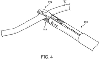
- the bipolar electrosurgical forceps 110 includes housing 111 and opposing jaw members 113 and 115 disposed at a distal end of a shaft 112.
- the jaw members 113 and 115 have one or more active electrodes 114 and a return electrode 116 disposed therein, respectively.
- the active electrode 114 and the return electrode 116 are connected to the generator 300 through cable 118 that includes the supply and return lines 14, 18 coupled to the active and return terminals 330, 332, respectively ( FIG. 3 ).
- the electrosurgical forceps 110 is coupled to the generator 300 at a connector having connections to the active and return terminals 330, 332 (e.g., pins) via a plug disposed at the end of the cable 118, wherein the plug includes contacts from the supply and return lines 14, 18 as described in more detail below.
- a connector having connections to the active and return terminals 330, 332 (e.g., pins) via a plug disposed at the end of the cable 118, wherein the plug includes contacts from the supply and return lines 14, 18 as described in more detail below.
- the bipolar electrosurgical forceps 210 includes a mechanical forceps 220 having an end effector 224 and a disposable electrode assembly 221.
- Mechanical forceps 220 includes first and second elongated shaft members 212, 214. Disposed at the proximal end portions of shaft members 212, 214 are handle members 216, 218, respectively, that are configured to allow a user to effect movement of at least one of the shaft members 212, 214 relative to the other.
- the end effector 224 includes opposing jaw members 242, 244 that extend from the distal end portions of shaft members 212, 214, respectively. The jaw members 242, 244 are movable relative to each other in response to movement of shaft members 212, 214.
- a housing 270 having a pair of housing halves 270a, 270b is configured to matingly engage and releasably encompass at least a portion of shaft member 214.
- Forceps 210 includes an electrical cable 228 extending from housing 270 configured to electrically connect forceps 210 to a source of electrosurgical energy, such as electrosurgical generator 300.
- Bipolar electrosurgical forceps 110 is substantially similar to bipolar electrosurgical forceps 210 except that bipolar electrical forceps 110 is configured for laparoscopic and/or endoscopic surgical procedures whereas bipolar electrosurgical forceps 210 is configured for open surgical procedures.
- the generator 300 may be any suitable type (e.g., electrosurgical, microwave, etc.) and may include a plurality of connectors 350-362 to accommodate various types of electrosurgical instruments (e.g., bipolar electrosurgical forceps 110, etc.).
- electrosurgical instruments e.g., bipolar electrosurgical forceps 110, etc.
- the generator 300 includes a user interface 341 having one or more display screens or information panels 342, 344, 346 for providing the user with a variety of output information (e.g., intensity settings, treatment complete indicators, etc.). Each of the screens 342, 344, 346 is associated with corresponding connector 350-362.
- the generator 300 includes suitable input controls (e.g., buttons, activators, switches, touch screen, etc.) for controlling the generator 300.
- the display screens 342, 344, 346 are also configured as touch screens that display a corresponding menu for the electrosurgical instruments (e.g., bipolar electrosurgical forceps 110, etc.). The user then adjusts inputs by simply touching corresponding menu options.
- Screen 342 controls the monopolar output and the devices connected to the connectors 350 and 352.
- Connector 350 is configured to couple to a monopolar electrosurgical instrument (e.g., monopolar electrosurgical instrument 12) and connector 352 is configured to couple to a foot switch (not shown). The foot switch provides for additional inputs (e.g., replicating inputs of the generator 300).
- Screen 344 controls monopolar and bipolar output and the devices connected to the connectors 356 and 358.
- Connector 356 is configured to couple to other monopolar instruments.
- Connector 358 is configured to couple to a bipolar instrument (e.g., bipolar electrosurgical forceps 110, 210, etc.).
- Screen 346 controls bipolar sealing procedures performed by the bipolar electrosurgical forceps 110 that may be plugged into the connectors 360 and 362.
- the generator 300 outputs energy through the connectors 360 and 362 suitable for sealing tissue grasped by the bipolar electrosurgical forceps 110.
- screen 346 outputs a user interface that allows the user to input a user-defined intensity setting.
- the user-defined setting may be any setting that allows the user to adjust one or more energy delivery parameters, such as power, current, voltage, energy, etc., or sealing parameters, such as energy rate limiters, sealing duration, etc.
- the user-defined setting is transmitted to the controller 324 where the setting may be saved in memory 326.
- the intensity setting may be a number scale, such as, for example, from one to ten or one to five. In embodiments, the intensity setting may be associated with an output curve of the generator 300.
- the intensity settings may be specific for each bipolar electrosurgical forceps 110 being utilized, such that various instruments provide the user with a specific intensity scale corresponding to the bipolar electrosurgical forceps 110.
- FIG. 3 shows a schematic block diagram of the generator 300 configured to output electrosurgical energy.
- the generator 300 includes a controller 324, a power supply 327, and a radio frequency (RF) amplifier (e.g., an RF output stage) 328.
- the power supply 327 is a high voltage, direct current (DC) power supply connected to an alternating current (AC) source (e.g., line voltage).
- the power supply 327 provides high voltage, DC power to the RF amplifier 328 via leads 327a and 327b.
- the RF amplifier 328 converts the high voltage, DC power into treatment energy (e.g., electro surgical) and delivers the treatment energy to the active terminal 330.
- the electrosurgical energy may be RF current.
- the treatment energy is returned to the RF amplifier 328 via the return terminal 332.
- the active and return terminals 330 and 332 are coupled to the RF amplifier 328 through an isolation transformer 329.
- the RF amplifier 328 is configured to operate in a plurality of modes, during which the generator 300 outputs corresponding waveforms having specific duty cycles, peak voltages, crest factors, etc. It is envisioned that in other embodiments, the generator 300 may be based on other types of suitable power supply topologies.
- the controller 324 includes a processor 325 operably connected to a memory 326, which may include one or more of volatile, non-volatile, magnetic, optical, or electrical media, such as read-only memory (ROM), random access memory (RAM), electrically-erasable programmable ROM (EEPROM), non-volatile RAM (NVRAM), or flash memory.
- the processor 325 may include one or more of a microprocessor, a digital signal processor (DSP), an application specific integrated circuit (ASIC), a field-programmable gate array (FPGA), or discrete logic circuitry.
- the processor 325 includes an output port that is operably connected to the power supply 327 and/or RF amplifier 328 allowing the processor 325 to control the output of the generator 300 according to either open and/or closed control loop schemes.
- a closed loop control scheme is a feedback control loop, in which a plurality of sensors measure a variety of tissue and energy properties (e.g., tissue impedance, tissue temperature, output power, current and/or voltage, etc.), and provide feedback to the controller 324. The controller 324 then sends control signals to the power supply 327 and/or RF amplifier 328 to adjust the high voltage, DC power and/or the RF current, respectively.
- processor 325 may be any suitable processor (e.g., control circuit) adapted to perform the operations, calculations, and/or set of instructions described in the present disclosure including, but not limited to, a hardware processor, a field programmable gate array (FPGA), a digital signal processor (DSP), a central processing unit (CPU), a microprocessor, and combinations thereof.
- a hardware processor e.g., a field programmable gate array (FPGA), a digital signal processor (DSP), a central processing unit (CPU), a microprocessor, and combinations thereof.
- FPGA field programmable gate array
- DSP digital signal processor
- CPU central processing unit
- microprocessor e.g., microprocessor
- the generator 300 includes a plurality of sensors 380, e.g., an RF current sensor 380a and an RF voltage sensor 380b.
- Various components of the generator 300 including the RF amplifier 328 and the RF current and voltage sensors 380a and 380b, may be disposed on a printed circuit board (PCB).
- the RF current sensor 380a is coupled to the active terminal 230 and provides measurements of the RF current supplied by the RF amplifier 328.
- the RF voltage sensor 380b is coupled to the active and return terminals 330 and 332, and provides measurements of the RF voltage supplied by the RF amplifier 328.
- the RF current and voltage sensors 380a and 380b may be coupled to active and return leads 328a and 328b, which interconnect the active and return terminals 330 and 332 to the RF amplifier 328, respectively.
- the RF current and voltage sensors 380a and 380b provide the sensed RF voltage and current signals, respectively, to the controller 324, which then may adjust the output of the power supply 327 and/or the RF amplifier 328 in response to the sensed RF voltage and current signals.
- the controller 324 also receives input signals from the input controls of the generator 300, the monopolar electrosurgical instrument 12, and/or the bipolar electrosurgical forceps 110. The controller 324 uses the input signals to adjust power output from the generator 300 and/or to perform other control functions.
- the tissue sealing systems and methods of the present disclosure control any combination of the following parameters: (1) the intensity, frequency, and/or duration of the electrosurgical energy applied to the tissue through the active electrodes 114, 116; (2) the pressure applied between the opposing jaw members 113, 115, respectively; and (3) the gap distance between opposing active electrodes 114, 116 during the sealing process.
- a detailed description of exemplary electrosurgical sealing devices and methods that control the pressure and gap distance are found, for example, in U.S. Patent No. 7,972,328 .
- each of the jaw members 113, 115 includes a pair of electrically conductive sealing plates 114, 116, respectively, disposed on respective inner-facing surfaces of the jaw members 113, 115.
- the bipolar electrosurgical forceps 110 is ready for selective application of electrosurgical energy as illustrated in FIG. 4 .
- the electrically conductive sealing plates 114, 116 cooperate to seal the tissue "T" held between the electrically conductive sealing plates 114, 116 upon the application of electrosurgical energy.
- the system 10 regulates the application of electrosurgical energy to achieve an effective tissue seal capable of withstanding high burst pressure.
- the generator 300 applies electrosurgical energy to tissue.
- Energy application is regulated by the controller 324 according to an algorithm stored within the memory 326.
- the algorithm maintains electrosurgical energy supplied to the tissue at constant voltage and varies the output power and/or current based on the type of tissue being sealed. For instance, thicker tissue typically needs more power, whereas thinner tissue needs less power. Therefore, the algorithm adjusts the output power based on tissue type by modifying various variables of the output power (e.g., voltage being maintained, duration of power application, etc.).
- the algorithm continually monitors the output power and may generate an alarm in response to an indication that the jaws of an electrosurgical instrument, such as bipolar electrosurgical forceps 110 and/or bipolar electrosurgical forceps 210, are in a slow open condition.
- a slow open condition occurs when the jaws of the electrosurgical instrument are opened at a sufficiently slow rate to avoid triggering an open circuit alarm while electrosurgical energy is still supplied to the electrodes of the jaw members, e.g., in response to activation of a hand switch or a foot switch.
- the jaws are not detected to be in an "open" state, and power continues to flow to the jaws, which is problematic for multiple reasons described above.
- non-causal derivative denotes a derivative taken at a center-point of an envelope of a predetermined time period, which may be from about 1ms to about 100ms, in embodiments, may be about 10ms.
- the method detects a slow open condition in electrosurgical system 10.
- power is provided to an electrosurgical instrument, such as bipolar electrosurgical forceps 110 and/or bipolar electrosurgical forceps 210.
- the controller 324 determines whether there is a phase shift between voltage and current waveforms of the electrosurgical waveform supplied to the electrosurgical instrument that exceeds a predetermined phase shift threshold.
- the phase shift threshold may be from about 1.3 to about 1.7 radians, in embodiments, from about 1.4 to about 1.6 radians.
- the phase shift indicates that the jaws of the electrosurgical instrument are in a slow open condition. If the phase shift exceeds the predetermined phase shift threshold, the process proceeds to step 516 where an alarm is activated. If the phase shift is less than the predetermined phase shift threshold, the process continues to step 506, to perform additional verification steps indicative of the slow open condition.
- the controller 324 determines whether impedance (Z) of the tissue is greater than an impedance threshold.
- the impedance threshold may be about 2500 ⁇ or more. If the controller 324 determines that Z exceeds the impedance threshold, this may also indicate that the jaws of the electrosurgical instrument are in a slow open condition. Alternatively, if a period of time during which the sealing process was expected to have been completed has expired, and Z exceeds the expected an end impedance threshold (endZ) by a predetermined offset, this may also indicate that the jaws of the electrosurgical instrument are in a slow open condition.
- the expected end impedance may be preprogrammed and stored in memory 326 of the generator 300.
- the memory 326 may store a plurality of end impedance values that are selected by the generator 300 based on the instrument and/or tissue being used.
- the offset impedance may be about 1500 ⁇ or more. If Z is greater than the sum of endZ and the offset, the process proceeds to step 516 where an alarm is activated. If Z does not exceed the sum of endZ and the offset, the process proceeds to step 508.
- controller 324 calculates dZ and determines whether dZ is greater than an upper dZ threshold. If the controller 324 determines that dZ exceeds the upper dZ threshold, this also indicates that the jaws of the electrosurgical instrument are in a slow open condition. If dZ is greater than the upper dZ threshold, the process proceeds to step 516 where an alarm is activated. If dZ does not exceed the upper dZ threshold, the process proceeds to step 510.
- the controller 324 determines whether the calculated dZ is less than a lower dZ threshold. If the controller 324 determines that the calculated dZ is less than the lower dZ threshold, this indicates that the sealing process is complete and the process ends. If dZ is not less than the lower dZ threshold, that signifies that dZ is between the first and lower dZ thresholds which indicates that the sealing process is approximating completion, and the process proceeds to step 512.
- system 10 continues to supply power to the electrosurgical instrument for a predetermined time, which may be about 100 ms, to allow the sealing process to complete, namely, until measured Z reaches the end impedance.
- step 514 the controller 324 performs the same determination as in step 504 above and determines whether the phase shift exceeding the phase shift threshold. If the phase shift exceeds the phase shift threshold, the process proceeds to step 516 where an alarm is activated. If the phase shift does not exceed the phase shift, the seal is complete, and the process ends.
Description
- The present disclosure relates to electrosurgical systems and computer-readable storage mediums for performing electrosurgical procedures. More particularly, the present disclosure relates to systems and computer-readable storage mediums for sealing tissue using electrosurgical forceps and for detecting whether the jaws of a vessel sealer are open during a sealing procedure.
- Electrosurgery involves application of high radio frequency electrical current to a surgical site to cut, ablate, or coagulate tissue. In monopolar electrosurgery, a source or active electrode delivers radio frequency alternating current from the electrosurgical generator to the targeted tissue. A patient return electrode is placed remotely from the active electrode to conduct the current back to the generator.
- In bipolar electrosurgery, return and active electrodes are placed in close proximity to each other such that an electrical circuit is formed between the two electrodes (e.g., in the case of an electrosurgical forceps). In this manner, the applied electrical current is limited to the body tissue positioned between the electrodes. Accordingly, bipolar electrosurgery generally involves the use of instruments where it is desired to achieve a focused delivery of electrosurgical energy between two electrodes positioned on the instrument, e.g. forceps or the like. Electrosurgical procedures outlined above may utilize various tissue and energy parameters in a feedback-based control system. Bipolar electrosurgery generally involves the use of forceps.
- A forceps is a pliers-like instrument which relies on mechanical action between its jaws to grasp, clamp and constrict vessels or tissue. "Open forceps" are commonly used in open surgical procedures whereas "endoscopic forceps" or "laparoscopic forceps" are used for less invasive endoscopic surgical procedures. Electrosurgical forceps (open or endoscopic) use mechanical clamping action and electrical energy to cause hemostasis on the clamped tissue. The forceps include electro surgically conductive plates which apply electrosurgical energy to the clamped tissue. By controlling the intensity, frequency, and duration of the electrosurgical energy applied through the conductive plates to the tissue, the surgeon can coagulate, cauterize, and/or seal tissue.
- During bipolar vessel sealing certain conditions may result in improper energy application. This may occur when bipolar electrodes are separated from one another without contacting tissue, which results in an open circuit or when the bipolar electrodes come in direct contact with each other and/or clamp on a highly conductive material (e.g., a surgical metallic clip or staple). In either of these instances, continual application of energy may result in injury to the patient and/or damage to the electrosurgical generator and other equipment. Thus, there is a need for new and improved systems and methods for detecting and responding to such conditions.
US2012283731 discloses an electro-surgical forceps which uses the impedance to detect an open-circuit state. - According to one embodiment, the present invention provides for a an electro-surgical generator and a computer-readable storage medium for detecting whether the jaws of an electrosurgical instrument are in a slow open condition. The invention is defined by the appended independent claims. Preferred embodiments are defined in the dependent claims.
- In an aspect of the present disclosure, an electrosurgical generator comprises an RF output stage configured to output an electrosurgical waveform through at least one pair of electrodes, sensing circuitry configured to measure a current of the electrosurgical waveform and an impedance between the at least one pair of electrodes configured to grasp tissue, and a controller configured to determine whether the impedance of the tissue disposed between the at least one pair of electrodes exceeds an impedance threshold, determine whether a change in the impedance is greater than an upper change in impedance threshold, and output an alarm indicative of the at least one pair of electrodes being at least partially open based on at least one of the impedance exceeding the impedance threshold or the change in impedance exceeding the change in impedance threshold.
- In another aspect of the present disclosure, the controller is further configured to determine whether the change in impedance is less than a lower change in impedance threshold.
- In a further aspect of the present disclosure, the controller is further configured to detect a phase shift of the electro surgical waveform, determine whether the phase shift exceeds a phase shift threshold, and activate the alarm based on the phase shift determination.
- In another aspect of the present disclosure, the controller is further configured to signal the RF output stage to output the electro surgical waveform for a time period if the change in impedance is between the lower and upper change in impedance thresholds.
- In a further aspect of the present disclosure, the controller is further configured to determine whether the phase shift exceeds the phase shift threshold, and activate the alarm if the phase shift exceeds the phase shift threshold.
- In an aspect of the present disclosure, a method of detecting whether the jaws of an electrosurgical instrument are in a slow open condition comprises outputting an electrosurgical waveform through at least one pair of electrodes of the electrosurgical instrument, measuring an impedance between the at least one pair of electrodes configured to grasp tissue, and determining whether the impedance of the tissue disposed between the at least one pair of electrodes exceeds an impedance threshold, determining whether a change in the impedance is greater than an upper change in impedance threshold, and outputting an alarm indicative of the at least one pair of electrodes being at least partially open based on at least one of the impedance exceeding the impedance threshold or the change in impedance exceeding the change in impedance threshold.
- In another aspect of the present disclosure, the method further comprises determining whether the change in impedance is less than a lower change in impedance threshold.
- In a further aspect of the present disclosure, the method further comprises detecting a phase shift of the electro surgical waveform, determining whether the phase shift exceeds a phase shift threshold, and activating the alarm based on the phase shift determination.
- In another aspect of the present disclosure, the method further comprises outputting the electrosurgical waveform for a time period if the change in impedance is between the lower and upper change in impedance thresholds.
- In a further aspect of the present disclosure, the method further comprises determining whether the phase shift exceeds the phase shift threshold, and activating the alarm if the phase shift exceeds the phase shift threshold.
- In an aspect of the present disclosure, a non-transitory computer-readable storage medium stores instructions which, when executed by a processor, cause an electrosurgical generator to output an electrosurgical waveform through at least one pair of electrodes of an electrosurgical instrument, measure an impedance between the at least one pair of electrodes configured to grasp tissue, determine whether the impedance of the tissue disposed between the at least one pair of electrodes exceeds an impedance threshold, determine whether a change in the impedance is greater than an upper change in impedance threshold, and output an alarm indicative of the at least one pair of electrodes being at least partially open based on at least one of the impedance exceeding the impedance threshold or the change in impedance exceeding the change in impedance threshold.
- In another aspect of the present disclosure, the instructions further cause the electrosurgical generator to determine whether the change in impedance is less than a lower change in impedance threshold.
- In a further aspect of the present disclosure, the instructions further cause the electrosurgical generator to detect a phase shift of the electrosurgical waveform, determine whether the phase shift exceeds a phase shift threshold, and activate the alarm based on the phase shift determination.
- In another aspect of the present disclosure, the instructions further cause the electrosurgical generator to output the electrosurgical waveform for a time period if the change in impedance is between the lower and upper change in impedance thresholds.
In a further aspect of the present disclosure, the instructions further cause the electrosurgical generator to determine whether the phase shift exceeds the phase shift threshold, and activate the alarm if the phase shift exceeds the phase shift threshold. - Various embodiments of the present disclosure are described herein with reference to the drawings wherein:
-
FIG. 1 is a perspective view of the components of an embodiment of an electrosurgical system according to the present disclosure; -
FIG. 2 is a front view of an embodiment of an electrosurgical generator ofFIG. 1 according to the present disclosure; -
FIG. 3 is a schematic, block diagram of the embodiment of the electrosurgical generator ofFIG. 1 according to the present disclosure; -
FIG. 4 is a rear, perspective view of an end effector of a bipolar forceps ofFIG. 1 shown grasping tissue; and -
FIG. 5 is a flow chart of a method executed on the generator of the invention. The method detects an open circuit. - Particular embodiments of the present disclosure will be described below with reference to the accompanying drawings. In the following description, well-known functions or constructions are not described in detail to avoid obscuring the present disclosure in unnecessary detail. Those skilled in the art will understand that the present disclosure may be adapted for use with either an endoscopic instrument, a laparoscopic instrument, or an open instrument. It should also be appreciated that different electrical and mechanical connections and other considerations may apply to each particular type of instrument.
- A generator according to the present disclosure can perform monopolar and/or bipolar electrosurgical procedures, including, for example, cutting, coagulation, ablation, and vessel sealing procedures. The generator may include a plurality of outputs for interfacing with various electrosurgical instruments (e.g., a monopolar instrument, return electrode, bipolar electrosurgical forceps, footswitch, etc.). Further, the generator includes electronic circuitry configured to generate radio frequency energy specifically suited for various electrosurgical modes (e.g., cut, blend, coagulate, division with hemostasis, fulgurate, spray, etc.) and procedures (e.g., monopolar, bipolar, vessel sealing). In embodiments, the generator may be embedded, integrated or otherwise coupled to the electrosurgical instruments providing for an all-in-one electrosurgical apparatus.
-
FIG. 1 is an illustration of a monopolar and bipolarelectrosurgical system 10 according to the present disclosure. Thesystem 10 may include one or more monopolarelectrosurgical instruments 12 having one or more active electrodes 13 (e.g., electrosurgical cutting probe, ablation electrodes, etc.) for treating tissue of a patient. Electrosurgical alternating current is supplied to theinstrument 12 by agenerator 300 via asupply line 14 that is connected to an active terminal 330 (FIG. 3 ) of thegenerator 300, allowing theinstrument 12 to cut, coagulate, ablate, and/or otherwise treat tissue. The alternating current is returned to thegenerator 300 through a return electrode pad 16 via areturn line 18 at a return terminal 332 (FIG. 3 ) of thegenerator 300. For monopolar operation, thesystem 10 may include a plurality of return electrode pads 16 that, in use, are disposed on a patient to minimize the chances of tissue damage by maximizing the overall contact area with the patient. In addition, thegenerator 300 and the return electrode pads 16 may be configured for monitoring so-called "tissue-to-patient" contact to ensure that sufficient contact exists between the return electrode pads 16 and the tissue to further minimize chances of tissue damage. - The
system 10 may also include one or more bipolar electrosurgical instruments, for example, a bipolarelectrosurgical forceps 110 or a bipolar electrosurgical forceps 210 having one or more electrodes for treating tissue of a patient. The bipolarelectrosurgical instruments 110, 210 may be used with open and/or laparoscopic surgical procedures. - The bipolar
electrosurgical forceps 110 includes housing 111 and opposingjaw members shaft 112. Thejaw members active electrodes 114 and areturn electrode 116 disposed therein, respectively. Theactive electrode 114 and thereturn electrode 116 are connected to thegenerator 300 throughcable 118 that includes the supply and returnlines terminals FIG. 3 ). Theelectrosurgical forceps 110 is coupled to thegenerator 300 at a connector having connections to the active and returnterminals 330, 332 (e.g., pins) via a plug disposed at the end of thecable 118, wherein the plug includes contacts from the supply and returnlines - The bipolar electrosurgical forceps 210 includes a mechanical forceps 220 having an
end effector 224 and adisposable electrode assembly 221. Mechanical forceps 220 includes first and secondelongated shaft members shaft members handle members shaft members end effector 224 includes opposingjaw members shaft members jaw members shaft members housing 270 having a pair ofhousing halves shaft member 214. Forceps 210 includes anelectrical cable 228 extending fromhousing 270 configured to electrically connect forceps 210 to a source of electrosurgical energy, such aselectrosurgical generator 300. - Bipolar
electrosurgical forceps 110 is substantially similar to bipolar electrosurgical forceps 210 except that bipolarelectrical forceps 110 is configured for laparoscopic and/or endoscopic surgical procedures whereas bipolar electrosurgical forceps 210 is configured for open surgical procedures. - With reference to
FIG. 2 , afront face 340 of thegenerator 300 is shown. Thegenerator 300 may be any suitable type (e.g., electrosurgical, microwave, etc.) and may include a plurality of connectors 350-362 to accommodate various types of electrosurgical instruments (e.g., bipolarelectrosurgical forceps 110, etc.). - The
generator 300 includes auser interface 341 having one or more display screens orinformation panels screens generator 300 includes suitable input controls (e.g., buttons, activators, switches, touch screen, etc.) for controlling thegenerator 300. The display screens 342, 344, 346 are also configured as touch screens that display a corresponding menu for the electrosurgical instruments (e.g., bipolarelectrosurgical forceps 110, etc.). The user then adjusts inputs by simply touching corresponding menu options. -
Screen 342 controls the monopolar output and the devices connected to theconnectors Connector 350 is configured to couple to a monopolar electrosurgical instrument (e.g., monopolar electrosurgical instrument 12) andconnector 352 is configured to couple to a foot switch (not shown). The foot switch provides for additional inputs (e.g., replicating inputs of the generator 300).Screen 344 controls monopolar and bipolar output and the devices connected to theconnectors Connector 356 is configured to couple to other monopolar instruments.Connector 358 is configured to couple to a bipolar instrument (e.g., bipolarelectrosurgical forceps 110, 210, etc.). -
Screen 346 controls bipolar sealing procedures performed by the bipolarelectrosurgical forceps 110 that may be plugged into theconnectors generator 300 outputs energy through theconnectors electrosurgical forceps 110. In particular,screen 346 outputs a user interface that allows the user to input a user-defined intensity setting. The user-defined setting may be any setting that allows the user to adjust one or more energy delivery parameters, such as power, current, voltage, energy, etc., or sealing parameters, such as energy rate limiters, sealing duration, etc. The user-defined setting is transmitted to thecontroller 324 where the setting may be saved inmemory 326. In embodiments, the intensity setting may be a number scale, such as, for example, from one to ten or one to five. In embodiments, the intensity setting may be associated with an output curve of thegenerator 300. The intensity settings may be specific for each bipolarelectrosurgical forceps 110 being utilized, such that various instruments provide the user with a specific intensity scale corresponding to the bipolarelectrosurgical forceps 110. -
FIG. 3 shows a schematic block diagram of thegenerator 300 configured to output electrosurgical energy. Thegenerator 300 includes acontroller 324, apower supply 327, and a radio frequency (RF) amplifier (e.g., an RF output stage) 328. Thepower supply 327 is a high voltage, direct current (DC) power supply connected to an alternating current (AC) source (e.g., line voltage). Thepower supply 327 provides high voltage, DC power to theRF amplifier 328 vialeads RF amplifier 328 converts the high voltage, DC power into treatment energy (e.g., electro surgical) and delivers the treatment energy to theactive terminal 330. The electrosurgical energy may be RF current. The treatment energy is returned to theRF amplifier 328 via thereturn terminal 332. The active and returnterminals RF amplifier 328 through an isolation transformer 329. - The
RF amplifier 328 is configured to operate in a plurality of modes, during which thegenerator 300 outputs corresponding waveforms having specific duty cycles, peak voltages, crest factors, etc. It is envisioned that in other embodiments, thegenerator 300 may be based on other types of suitable power supply topologies. - The
controller 324 includes aprocessor 325 operably connected to amemory 326, which may include one or more of volatile, non-volatile, magnetic, optical, or electrical media, such as read-only memory (ROM), random access memory (RAM), electrically-erasable programmable ROM (EEPROM), non-volatile RAM (NVRAM), or flash memory. Theprocessor 325 may include one or more of a microprocessor, a digital signal processor (DSP), an application specific integrated circuit (ASIC), a field-programmable gate array (FPGA), or discrete logic circuitry. Theprocessor 325 includes an output port that is operably connected to thepower supply 327 and/orRF amplifier 328 allowing theprocessor 325 to control the output of thegenerator 300 according to either open and/or closed control loop schemes. A closed loop control scheme is a feedback control loop, in which a plurality of sensors measure a variety of tissue and energy properties (e.g., tissue impedance, tissue temperature, output power, current and/or voltage, etc.), and provide feedback to thecontroller 324. Thecontroller 324 then sends control signals to thepower supply 327 and/orRF amplifier 328 to adjust the high voltage, DC power and/or the RF current, respectively. Those skilled in the art will appreciate that theprocessor 325 may be any suitable processor (e.g., control circuit) adapted to perform the operations, calculations, and/or set of instructions described in the present disclosure including, but not limited to, a hardware processor, a field programmable gate array (FPGA), a digital signal processor (DSP), a central processing unit (CPU), a microprocessor, and combinations thereof. - The
generator 300 according to the present disclosure includes a plurality ofsensors 380, e.g., an RFcurrent sensor 380a and anRF voltage sensor 380b. Various components of thegenerator 300, including theRF amplifier 328 and the RF current andvoltage sensors current sensor 380a is coupled to the active terminal 230 and provides measurements of the RF current supplied by theRF amplifier 328. TheRF voltage sensor 380b is coupled to the active and returnterminals RF amplifier 328. In embodiments, the RF current andvoltage sensors terminals RF amplifier 328, respectively. - The RF current and
voltage sensors controller 324, which then may adjust the output of thepower supply 327 and/or theRF amplifier 328 in response to the sensed RF voltage and current signals. Thecontroller 324 also receives input signals from the input controls of thegenerator 300, the monopolarelectrosurgical instrument 12, and/or the bipolarelectrosurgical forceps 110. Thecontroller 324 uses the input signals to adjust power output from thegenerator 300 and/or to perform other control functions. - To achieve an effective tissue seal, the tissue sealing systems and methods of the present disclosure control any combination of the following parameters: (1) the intensity, frequency, and/or duration of the electrosurgical energy applied to the tissue through the
active electrodes jaw members active electrodes U.S. Patent No. 7,972,328 . - Since the bipolar
electrosurgical forceps 110 apply electrosurgical energy through electrodes, each of thejaw members conductive sealing plates jaw members jaw members electrosurgical forceps 110 is ready for selective application of electrosurgical energy as illustrated inFIG. 4 . At that point, the electricallyconductive sealing plates conductive sealing plates - The
system 10 according to the present disclosure regulates the application of electrosurgical energy to achieve an effective tissue seal capable of withstanding high burst pressure. Thegenerator 300 applies electrosurgical energy to tissue. Energy application is regulated by thecontroller 324 according to an algorithm stored within thememory 326. The algorithm maintains electrosurgical energy supplied to the tissue at constant voltage and varies the output power and/or current based on the type of tissue being sealed. For instance, thicker tissue typically needs more power, whereas thinner tissue needs less power. Therefore, the algorithm adjusts the output power based on tissue type by modifying various variables of the output power (e.g., voltage being maintained, duration of power application, etc.). - The algorithm continually monitors the output power and may generate an alarm in response to an indication that the jaws of an electrosurgical instrument, such as bipolar
electrosurgical forceps 110 and/or bipolar electrosurgical forceps 210, are in a slow open condition. A slow open condition occurs when the jaws of the electrosurgical instrument are opened at a sufficiently slow rate to avoid triggering an open circuit alarm while electrosurgical energy is still supplied to the electrodes of the jaw members, e.g., in response to activation of a hand switch or a foot switch. In such an instance, the jaws are not detected to be in an "open" state, and power continues to flow to the jaws, which is problematic for multiple reasons described above. Various systems and methods are contemplated by the present disclosure for determining whether the jaws of the electrosurgical instrument are in a slow open condition. Some methods, as described in more detail below, evaluate impedance (Z), a change in impedance, which is expressed as a non-causal derivative of the impedance, dZ, and/or a rate of change of impedance, which is expressed as the derivative of the impedance over time, dZ/dt. As used herein, non-causal derivative denotes a derivative taken at a center-point of an envelope of a predetermined time period, which may be from about 1ms to about 100ms, in embodiments, may be about 10ms. - Referring now to
FIG. 5 , a flowchart of a method executed on the generator of the invention is shown. The method detects a slow open condition inelectrosurgical system 10. Starting atstep 502, power is provided to an electrosurgical instrument, such as bipolarelectrosurgical forceps 110 and/or bipolar electrosurgical forceps 210. Atstep 504, thecontroller 324 determines whether there is a phase shift between voltage and current waveforms of the electrosurgical waveform supplied to the electrosurgical instrument that exceeds a predetermined phase shift threshold. In embodiments, the phase shift threshold may be from about 1.3 to about 1.7 radians, in embodiments, from about 1.4 to about 1.6 radians. The phase shift indicates that the jaws of the electrosurgical instrument are in a slow open condition. If the phase shift exceeds the predetermined phase shift threshold, the process proceeds to step 516 where an alarm is activated. If the phase shift is less than the predetermined phase shift threshold, the process continues to step 506, to perform additional verification steps indicative of the slow open condition. - At
step 506, thecontroller 324 determines whether impedance (Z) of the tissue is greater than an impedance threshold. In embodiments, the impedance threshold may be about 2500 Ω or more. If thecontroller 324 determines that Z exceeds the impedance threshold, this may also indicate that the jaws of the electrosurgical instrument are in a slow open condition. Alternatively, if a period of time during which the sealing process was expected to have been completed has expired, and Z exceeds the expected an end impedance threshold (endZ) by a predetermined offset, this may also indicate that the jaws of the electrosurgical instrument are in a slow open condition. The expected end impedance may be preprogrammed and stored inmemory 326 of thegenerator 300. Thememory 326 may store a plurality of end impedance values that are selected by thegenerator 300 based on the instrument and/or tissue being used. In embodiments, the offset impedance may be about 1500 Ω or more. If Z is greater than the sum of endZ and the offset, the process proceeds to step 516 where an alarm is activated. If Z does not exceed the sum of endZ and the offset, the process proceeds to step 508. - At
step 508,controller 324 calculates dZ and determines whether dZ is greater than an upper dZ threshold. If thecontroller 324 determines that dZ exceeds the upper dZ threshold, this also indicates that the jaws of the electrosurgical instrument are in a slow open condition. If dZ is greater than the upper dZ threshold, the process proceeds to step 516 where an alarm is activated. If dZ does not exceed the upper dZ threshold, the process proceeds to step 510. - At
step 510, thecontroller 324 determines whether the calculated dZ is less than a lower dZ threshold. If thecontroller 324 determines that the calculated dZ is less than the lower dZ threshold, this indicates that the sealing process is complete and the process ends. If dZ is not less than the lower dZ threshold, that signifies that dZ is between the first and lower dZ thresholds which indicates that the sealing process is approximating completion, and the process proceeds to step 512. - At
step 512,system 10 continues to supply power to the electrosurgical instrument for a predetermined time, which may be about 100 ms, to allow the sealing process to complete, namely, until measured Z reaches the end impedance. - Thereafter, at
step 514, thecontroller 324 performs the same determination as instep 504 above and determines whether the phase shift exceeding the phase shift threshold. If the phase shift exceeds the phase shift threshold, the process proceeds to step 516 where an alarm is activated. If the phase shift does not exceed the phase shift, the seal is complete, and the process ends. - While several embodiments of the disclosure have been shown in the drawings and/or described herein, it is not intended that the disclosure be limited thereto, as it is intended that the disclosure be as broad in scope as the art will allow and that the specification be read likewise. Therefore, the above description should not be construed as limiting, but merely as exemplifications of particular embodiments. Those skilled in the art will envision other modifications within the scope of the claims appended hereto.
Claims (10)
- An electrosurgical generator (300), comprising:an RF output stage (328) configured to output an electrosurgical waveform through at least one pair of electrodes;sensing circuitry configured to measure an impedance between the at least one pair of electrodes configured to grasp tissue; anda controller (324), characterized in that the controller is configured to:(a) determine whether the impedance of the tissue disposed between the at least one pair of electrodes exceeds an impedance threshold indicative of the at least one pair of electrodes being at least partially open;(b) subsequently determine whether a change in the impedance is greater than an upper change in impedance threshold indicative of the at least one pair of electrodes being at least partially open, wherein said change in impedance is a non-causal derivative of the impedance (dZ) taken at a center-point of an envelope of a predetermined time period of from 1ms to 100ms, or a derivative of the impedance over time (dZ/dt); andoutput an alarm indicative of the at least one pair of electrodes being at least partially open based on at least one of the impedance exceeding the impedance threshold or the change in impedance exceeding the change in impedance threshold.
- The electrosurgical generator according to claim 1, wherein following step (b) the controller (324) is further configured to determine whether the change in impedance is less than a lower change in impedance threshold indicative that the sealing process is complete.
- The electrosurgical generator according to claim 2, wherein the controller (324) is further configured to signal the RF output stage (328) to output the electrosurgical waveform for a time period if the change in impedance is between the lower and upper change in impedance thresholds.
- The electrosurgical generator according to any preceding claim, wherein the controller (324) is further configured to:detect a phase shift of the electrosurgical waveform;determine whether the phase shift exceeds a phase shift threshold; andactivate the alarm based on the phase shift determination.
- The electrosurgical generator according to claim 4, wherein the controller is configured to activate the alarm if the phase shift exceeds the phase shift threshold.
- A non-transitory computer-readable storage medium storing instructions which, when executed by a processor, cause an electrosurgical generator to:output an electrosurgical waveform through at least one pair of electrodes of an electrosurgical instrument;measure an impedance between the at least one pair of electrodes configured to grasp tissue;characterized in that said instructions further cause the electrosurgical generator to:(a) determine whether the impedance of the tissue disposed between the at least one pair of electrodes exceeds an impedance threshold indicative of the at least one pair of electrodes being at least partially open;(b) subsequently determine whether a change in the impedance is greater than an upper change in impedance threshold indicative of the at least one pair of electrodes being at least partially open, wherein said change in impedance is a non-causal derivative of the impedance (dZ) taken at a center-point of an envelope of a predetermined time period of from 1ms to 100ms, or a derivative of the impedance over time (dZ/dt); andoutput an alarm indicative of the at least one pair of electrodes being at least partially open based on at least one of the impedance exceeding the impedance threshold or the change in impedance exceeding the change in impedance threshold.
- The non-transitory computer-readable storage medium according to claim 6, wherein the instructions further cause the electrosurgical generator to determine following said step (b) whether the change in impedance is less than a lower change in impedance threshold indicative that the sealing process is complete.
- The non-transitory computer-readable storage medium according to claim 7, wherein the instructions further cause the electrosurgical generator to output the electrosurgical waveform for a time period if the change in impedance is between the lower and upper change in impedance thresholds.
- The non-transitory computer-readable storage medium according to claim 6, 7 or 8, wherein the instructions further cause the electrosurgical generator to:detect a phase shift of the electrosurgical waveform;determine whether the phase shift exceeds a phase shift threshold; andactivate the alarm based on the phase shift determination.
- The non-transitory computer-readable storage medium according to claim 9, wherein the instructions cause the electrosurgical generator to
activate the alarm if the phase shift exceeds the phase shift threshold.
Applications Claiming Priority (2)
| Application Number | Priority Date | Filing Date | Title |
|---|---|---|---|
| US201562181902P | 2015-06-19 | 2015-06-19 | |
| US15/173,023 US10512499B2 (en) | 2015-06-19 | 2016-06-03 | Systems and methods for detecting opening of the jaws of a vessel sealer mid-seal |
Publications (2)
| Publication Number | Publication Date |
|---|---|
| EP3106115A1 EP3106115A1 (en) | 2016-12-21 |
| EP3106115B1 true EP3106115B1 (en) | 2018-05-23 |
Family
ID=56134224
Family Applications (1)
| Application Number | Title | Priority Date | Filing Date |
|---|---|---|---|
| EP16174916.3A Active EP3106115B1 (en) | 2015-06-19 | 2016-06-17 | Systems for detecting opening of the jaws of a vessel sealer mid-seal |
Country Status (2)
| Country | Link |
|---|---|
| US (2) | US10512499B2 (en) |
| EP (1) | EP3106115B1 (en) |
Families Citing this family (108)
| Publication number | Priority date | Publication date | Assignee | Title |
|---|---|---|---|---|
| US11871901B2 (en) | 2012-05-20 | 2024-01-16 | Cilag Gmbh International | Method for situational awareness for surgical network or surgical network connected device capable of adjusting function based on a sensed situation or usage |
| US11504192B2 (en) | 2014-10-30 | 2022-11-22 | Cilag Gmbh International | Method of hub communication with surgical instrument systems |
| US11311342B2 (en) | 2017-10-30 | 2022-04-26 | Cilag Gmbh International | Method for communicating with surgical instrument systems |
| US11911045B2 (en) | 2017-10-30 | 2024-02-27 | Cllag GmbH International | Method for operating a powered articulating multi-clip applier |
| US11564756B2 (en) | 2017-10-30 | 2023-01-31 | Cilag Gmbh International | Method of hub communication with surgical instrument systems |
| US11510741B2 (en) | 2017-10-30 | 2022-11-29 | Cilag Gmbh International | Method for producing a surgical instrument comprising a smart electrical system |
| US11123070B2 (en) | 2017-10-30 | 2021-09-21 | Cilag Gmbh International | Clip applier comprising a rotatable clip magazine |
| US11801098B2 (en) | 2017-10-30 | 2023-10-31 | Cilag Gmbh International | Method of hub communication with surgical instrument systems |
| US11229436B2 (en) | 2017-10-30 | 2022-01-25 | Cilag Gmbh International | Surgical system comprising a surgical tool and a surgical hub |
| US11317919B2 (en) | 2017-10-30 | 2022-05-03 | Cilag Gmbh International | Clip applier comprising a clip crimping system |
| US11291510B2 (en) | 2017-10-30 | 2022-04-05 | Cilag Gmbh International | Method of hub communication with surgical instrument systems |
| US11026712B2 (en) | 2017-10-30 | 2021-06-08 | Cilag Gmbh International | Surgical instruments comprising a shifting mechanism |
| US11602393B2 (en) | 2017-12-28 | 2023-03-14 | Cilag Gmbh International | Surgical evacuation sensing and generator control |
| US11179208B2 (en) | 2017-12-28 | 2021-11-23 | Cilag Gmbh International | Cloud-based medical analytics for security and authentication trends and reactive measures |
| US11559308B2 (en) | 2017-12-28 | 2023-01-24 | Cilag Gmbh International | Method for smart energy device infrastructure |
| US11678881B2 (en) | 2017-12-28 | 2023-06-20 | Cilag Gmbh International | Spatial awareness of surgical hubs in operating rooms |
| US11864728B2 (en) | 2017-12-28 | 2024-01-09 | Cilag Gmbh International | Characterization of tissue irregularities through the use of mono-chromatic light refractivity |
| US11896443B2 (en) | 2017-12-28 | 2024-02-13 | Cilag Gmbh International | Control of a surgical system through a surgical barrier |
| US11202570B2 (en) | 2017-12-28 | 2021-12-21 | Cilag Gmbh International | Communication hub and storage device for storing parameters and status of a surgical device to be shared with cloud based analytics systems |
| US11308075B2 (en) | 2017-12-28 | 2022-04-19 | Cilag Gmbh International | Surgical network, instrument, and cloud responses based on validation of received dataset and authentication of its source and integrity |
| US11432885B2 (en) | 2017-12-28 | 2022-09-06 | Cilag Gmbh International | Sensing arrangements for robot-assisted surgical platforms |
| US11419667B2 (en) | 2017-12-28 | 2022-08-23 | Cilag Gmbh International | Ultrasonic energy device which varies pressure applied by clamp arm to provide threshold control pressure at a cut progression location |
| US11857152B2 (en) | 2017-12-28 | 2024-01-02 | Cilag Gmbh International | Surgical hub spatial awareness to determine devices in operating theater |
| US11166772B2 (en) | 2017-12-28 | 2021-11-09 | Cilag Gmbh International | Surgical hub coordination of control and communication of operating room devices |
| US11633237B2 (en) | 2017-12-28 | 2023-04-25 | Cilag Gmbh International | Usage and technique analysis of surgeon / staff performance against a baseline to optimize device utilization and performance for both current and future procedures |
| US11903601B2 (en) | 2017-12-28 | 2024-02-20 | Cilag Gmbh International | Surgical instrument comprising a plurality of drive systems |
| US11076921B2 (en) | 2017-12-28 | 2021-08-03 | Cilag Gmbh International | Adaptive control program updates for surgical hubs |
| US11273001B2 (en) | 2017-12-28 | 2022-03-15 | Cilag Gmbh International | Surgical hub and modular device response adjustment based on situational awareness |
| US11147607B2 (en) | 2017-12-28 | 2021-10-19 | Cilag Gmbh International | Bipolar combination device that automatically adjusts pressure based on energy modality |
| US11096693B2 (en) | 2017-12-28 | 2021-08-24 | Cilag Gmbh International | Adjustment of staple height of at least one row of staples based on the sensed tissue thickness or force in closing |
| US11304720B2 (en) | 2017-12-28 | 2022-04-19 | Cilag Gmbh International | Activation of energy devices |
| US11304745B2 (en) | 2017-12-28 | 2022-04-19 | Cilag Gmbh International | Surgical evacuation sensing and display |
| US11423007B2 (en) | 2017-12-28 | 2022-08-23 | Cilag Gmbh International | Adjustment of device control programs based on stratified contextual data in addition to the data |
| US11109866B2 (en) | 2017-12-28 | 2021-09-07 | Cilag Gmbh International | Method for circular stapler control algorithm adjustment based on situational awareness |
| US11257589B2 (en) | 2017-12-28 | 2022-02-22 | Cilag Gmbh International | Real-time analysis of comprehensive cost of all instrumentation used in surgery utilizing data fluidity to track instruments through stocking and in-house processes |
| US10758310B2 (en) | 2017-12-28 | 2020-09-01 | Ethicon Llc | Wireless pairing of a surgical device with another device within a sterile surgical field based on the usage and situational awareness of devices |
| US11311306B2 (en) | 2017-12-28 | 2022-04-26 | Cilag Gmbh International | Surgical systems for detecting end effector tissue distribution irregularities |
| US11559307B2 (en) | 2017-12-28 | 2023-01-24 | Cilag Gmbh International | Method of robotic hub communication, detection, and control |
| US11266468B2 (en) | 2017-12-28 | 2022-03-08 | Cilag Gmbh International | Cooperative utilization of data derived from secondary sources by intelligent surgical hubs |
| US11571234B2 (en) | 2017-12-28 | 2023-02-07 | Cilag Gmbh International | Temperature control of ultrasonic end effector and control system therefor |
| US20190201042A1 (en) | 2017-12-28 | 2019-07-04 | Ethicon Llc | Determining the state of an ultrasonic electromechanical system according to frequency shift |
| US11234756B2 (en) | 2017-12-28 | 2022-02-01 | Cilag Gmbh International | Powered surgical tool with predefined adjustable control algorithm for controlling end effector parameter |
| US11324557B2 (en) | 2017-12-28 | 2022-05-10 | Cilag Gmbh International | Surgical instrument with a sensing array |
| US11376002B2 (en) | 2017-12-28 | 2022-07-05 | Cilag Gmbh International | Surgical instrument cartridge sensor assemblies |
| US11786245B2 (en) | 2017-12-28 | 2023-10-17 | Cilag Gmbh International | Surgical systems with prioritized data transmission capabilities |
| US11364075B2 (en) | 2017-12-28 | 2022-06-21 | Cilag Gmbh International | Radio frequency energy device for delivering combined electrical signals |
| US11317937B2 (en) | 2018-03-08 | 2022-05-03 | Cilag Gmbh International | Determining the state of an ultrasonic end effector |
| US11056244B2 (en) | 2017-12-28 | 2021-07-06 | Cilag Gmbh International | Automated data scaling, alignment, and organizing based on predefined parameters within surgical networks |
| US11389164B2 (en) | 2017-12-28 | 2022-07-19 | Cilag Gmbh International | Method of using reinforced flexible circuits with multiple sensors to optimize performance of radio frequency devices |
| US11013563B2 (en) | 2017-12-28 | 2021-05-25 | Ethicon Llc | Drive arrangements for robot-assisted surgical platforms |
| US11937769B2 (en) | 2017-12-28 | 2024-03-26 | Cilag Gmbh International | Method of hub communication, processing, storage and display |
| US11896322B2 (en) | 2017-12-28 | 2024-02-13 | Cilag Gmbh International | Sensing the patient position and contact utilizing the mono-polar return pad electrode to provide situational awareness to the hub |
| US11659023B2 (en) | 2017-12-28 | 2023-05-23 | Cilag Gmbh International | Method of hub communication |
| US11589888B2 (en) | 2017-12-28 | 2023-02-28 | Cilag Gmbh International | Method for controlling smart energy devices |
| US11284936B2 (en) | 2017-12-28 | 2022-03-29 | Cilag Gmbh International | Surgical instrument having a flexible electrode |
| US11672605B2 (en) | 2017-12-28 | 2023-06-13 | Cilag Gmbh International | Sterile field interactive control displays |
| US10595887B2 (en) | 2017-12-28 | 2020-03-24 | Ethicon Llc | Systems for adjusting end effector parameters based on perioperative information |
| US20190201142A1 (en) | 2017-12-28 | 2019-07-04 | Ethicon Llc | Automatic tool adjustments for robot-assisted surgical platforms |
| US11304699B2 (en) | 2017-12-28 | 2022-04-19 | Cilag Gmbh International | Method for adaptive control schemes for surgical network control and interaction |
| US10898622B2 (en) | 2017-12-28 | 2021-01-26 | Ethicon Llc | Surgical evacuation system with a communication circuit for communication between a filter and a smoke evacuation device |
| US11304763B2 (en) | 2017-12-28 | 2022-04-19 | Cilag Gmbh International | Image capturing of the areas outside the abdomen to improve placement and control of a surgical device in use |
| US10892995B2 (en) | 2017-12-28 | 2021-01-12 | Ethicon Llc | Surgical network determination of prioritization of communication, interaction, or processing based on system or device needs |
| US11291495B2 (en) * | 2017-12-28 | 2022-04-05 | Cilag Gmbh International | Interruption of energy due to inadvertent capacitive coupling |
| US11160605B2 (en) | 2017-12-28 | 2021-11-02 | Cilag Gmbh International | Surgical evacuation sensing and motor control |
| US11424027B2 (en) | 2017-12-28 | 2022-08-23 | Cilag Gmbh International | Method for operating surgical instrument systems |
| US11132462B2 (en) | 2017-12-28 | 2021-09-28 | Cilag Gmbh International | Data stripping method to interrogate patient records and create anonymized record |
| US11596291B2 (en) | 2017-12-28 | 2023-03-07 | Cilag Gmbh International | Method of compressing tissue within a stapling device and simultaneously displaying of the location of the tissue within the jaws |
| US11253315B2 (en) | 2017-12-28 | 2022-02-22 | Cilag Gmbh International | Increasing radio frequency to create pad-less monopolar loop |
| US11832899B2 (en) | 2017-12-28 | 2023-12-05 | Cilag Gmbh International | Surgical systems with autonomously adjustable control programs |
| US11818052B2 (en) | 2017-12-28 | 2023-11-14 | Cilag Gmbh International | Surgical network determination of prioritization of communication, interaction, or processing based on system or device needs |
| US11786251B2 (en) | 2017-12-28 | 2023-10-17 | Cilag Gmbh International | Method for adaptive control schemes for surgical network control and interaction |
| US11666331B2 (en) | 2017-12-28 | 2023-06-06 | Cilag Gmbh International | Systems for detecting proximity of surgical end effector to cancerous tissue |
| US11446052B2 (en) | 2017-12-28 | 2022-09-20 | Cilag Gmbh International | Variation of radio frequency and ultrasonic power level in cooperation with varying clamp arm pressure to achieve predefined heat flux or power applied to tissue |
| US11464535B2 (en) | 2017-12-28 | 2022-10-11 | Cilag Gmbh International | Detection of end effector emersion in liquid |
| US11051876B2 (en) | 2017-12-28 | 2021-07-06 | Cilag Gmbh International | Surgical evacuation flow paths |
| US11832840B2 (en) | 2017-12-28 | 2023-12-05 | Cilag Gmbh International | Surgical instrument having a flexible circuit |
| US11464559B2 (en) | 2017-12-28 | 2022-10-11 | Cilag Gmbh International | Estimating state of ultrasonic end effector and control system therefor |
| US11529187B2 (en) | 2017-12-28 | 2022-12-20 | Cilag Gmbh International | Surgical evacuation sensor arrangements |
| US11576677B2 (en) | 2017-12-28 | 2023-02-14 | Cilag Gmbh International | Method of hub communication, processing, display, and cloud analytics |
| US11100631B2 (en) | 2017-12-28 | 2021-08-24 | Cilag Gmbh International | Use of laser light and red-green-blue coloration to determine properties of back scattered light |
| US11612444B2 (en) | 2017-12-28 | 2023-03-28 | Cilag Gmbh International | Adjustment of a surgical device function based on situational awareness |
| US11771487B2 (en) | 2017-12-28 | 2023-10-03 | Cilag Gmbh International | Mechanisms for controlling different electromechanical systems of an electrosurgical instrument |
| US11744604B2 (en) | 2017-12-28 | 2023-09-05 | Cilag Gmbh International | Surgical instrument with a hardware-only control circuit |
| US11419630B2 (en) | 2017-12-28 | 2022-08-23 | Cilag Gmbh International | Surgical system distributed processing |
| US11540855B2 (en) | 2017-12-28 | 2023-01-03 | Cilag Gmbh International | Controlling activation of an ultrasonic surgical instrument according to the presence of tissue |
| US11278281B2 (en) | 2017-12-28 | 2022-03-22 | Cilag Gmbh International | Interactive surgical system |
| US11410259B2 (en) | 2017-12-28 | 2022-08-09 | Cilag Gmbh International | Adaptive control program updates for surgical devices |
| US11678927B2 (en) | 2018-03-08 | 2023-06-20 | Cilag Gmbh International | Detection of large vessels during parenchymal dissection using a smart blade |
| US11259830B2 (en) | 2018-03-08 | 2022-03-01 | Cilag Gmbh International | Methods for controlling temperature in ultrasonic device |
| US11464532B2 (en) | 2018-03-08 | 2022-10-11 | Cilag Gmbh International | Methods for estimating and controlling state of ultrasonic end effector |
| US11278280B2 (en) | 2018-03-28 | 2022-03-22 | Cilag Gmbh International | Surgical instrument comprising a jaw closure lockout |
| US11197668B2 (en) | 2018-03-28 | 2021-12-14 | Cilag Gmbh International | Surgical stapling assembly comprising a lockout and an exterior access orifice to permit artificial unlocking of the lockout |
| US11471156B2 (en) | 2018-03-28 | 2022-10-18 | Cilag Gmbh International | Surgical stapling devices with improved rotary driven closure systems |
| US11096688B2 (en) | 2018-03-28 | 2021-08-24 | Cilag Gmbh International | Rotary driven firing members with different anvil and channel engagement features |
| US11219453B2 (en) | 2018-03-28 | 2022-01-11 | Cilag Gmbh International | Surgical stapling devices with cartridge compatible closure and firing lockout arrangements |
| US11207067B2 (en) | 2018-03-28 | 2021-12-28 | Cilag Gmbh International | Surgical stapling device with separate rotary driven closure and firing systems and firing member that engages both jaws while firing |
| US11259806B2 (en) | 2018-03-28 | 2022-03-01 | Cilag Gmbh International | Surgical stapling devices with features for blocking advancement of a camming assembly of an incompatible cartridge installed therein |
| US11090047B2 (en) | 2018-03-28 | 2021-08-17 | Cilag Gmbh International | Surgical instrument comprising an adaptive control system |
| US11291445B2 (en) | 2019-02-19 | 2022-04-05 | Cilag Gmbh International | Surgical staple cartridges with integral authentication keys |
| US11357503B2 (en) | 2019-02-19 | 2022-06-14 | Cilag Gmbh International | Staple cartridge retainers with frangible retention features and methods of using same |
| US11751872B2 (en) | 2019-02-19 | 2023-09-12 | Cilag Gmbh International | Insertable deactivator element for surgical stapler lockouts |
| US11317915B2 (en) | 2019-02-19 | 2022-05-03 | Cilag Gmbh International | Universal cartridge based key feature that unlocks multiple lockout arrangements in different surgical staplers |
| US11369377B2 (en) | 2019-02-19 | 2022-06-28 | Cilag Gmbh International | Surgical stapling assembly with cartridge based retainer configured to unlock a firing lockout |
| JP7318006B2 (en) | 2019-05-09 | 2023-07-31 | ジャイラス エーシーエムアイ インク ディー/ビー/エー オリンパス サージカル テクノロジーズ アメリカ | Energy evaluation of electrosurgical systems |
| USD964564S1 (en) | 2019-06-25 | 2022-09-20 | Cilag Gmbh International | Surgical staple cartridge retainer with a closure system authentication key |
| USD950728S1 (en) | 2019-06-25 | 2022-05-03 | Cilag Gmbh International | Surgical staple cartridge |
| USD952144S1 (en) | 2019-06-25 | 2022-05-17 | Cilag Gmbh International | Surgical staple cartridge retainer with firing system authentication key |
| WO2024033749A1 (en) * | 2022-08-08 | 2024-02-15 | Covidien Lp | Electrosurgical systems and methods facilitating monopolar and/or bipolar electrosurgical tissue treatment |
Citations (2)
| Publication number | Priority date | Publication date | Assignee | Title |
|---|---|---|---|---|
| WO2012045095A1 (en) * | 2010-10-01 | 2012-04-05 | Applied Medical Resources Corporation | Electrosurgical instruments with jaws and/or an electrode and amplifiers for electrosurgery |
| EP2578172A2 (en) * | 2011-10-03 | 2013-04-10 | Ethicon Endo-Surgery, Inc. | Surgical generator for ultrasonic and electrosurgical devices |
Family Cites Families (15)
| Publication number | Priority date | Publication date | Assignee | Title |
|---|---|---|---|---|
| DE69432252T2 (en) | 1993-04-30 | 2003-12-18 | Medical Scient Inc | ELECTROSURGICAL IMPEDANCE FEEDBACK SYSTEM |
| US7276068B2 (en) | 2002-10-04 | 2007-10-02 | Sherwood Services Ag | Vessel sealing instrument with electrical cutting mechanism |
| US7678105B2 (en) | 2005-09-16 | 2010-03-16 | Conmed Corporation | Method and apparatus for precursively controlling energy during coaptive tissue fusion |
| US9186200B2 (en) * | 2006-01-24 | 2015-11-17 | Covidien Ag | System and method for tissue sealing |
| US7972328B2 (en) | 2006-01-24 | 2011-07-05 | Covidien Ag | System and method for tissue sealing |
| US8496653B2 (en) * | 2007-04-23 | 2013-07-30 | Boston Scientific Scimed, Inc. | Thrombus removal |
| US7972335B2 (en) | 2007-10-16 | 2011-07-05 | Conmed Corporation | Coaptive tissue fusion method and apparatus with current derivative precursive energy termination control |
| US7972334B2 (en) | 2007-10-16 | 2011-07-05 | Conmed Corporation | Coaptive tissue fusion method and apparatus with energy derivative precursive energy termination control |
| US8343144B2 (en) | 2008-02-11 | 2013-01-01 | Expandoheat, Llc | Apparatus and method for vessel sealing and tissue coagulation |
| US8357158B2 (en) | 2008-04-22 | 2013-01-22 | Covidien Lp | Jaw closure detection system |
| US8262652B2 (en) * | 2009-01-12 | 2012-09-11 | Tyco Healthcare Group Lp | Imaginary impedance process monitoring and intelligent shut-off |
| AU2011236083A1 (en) * | 2010-10-20 | 2012-05-10 | Maria G. Aboytes | Catheter apparatuses having expandable mesh structures for renal neuromodulation and associated systems and methods |
| US9539050B2 (en) | 2011-04-12 | 2017-01-10 | Covidien Lp | System and method for process monitoring and intelligent shut-off |
| US20130304066A1 (en) | 2012-05-09 | 2013-11-14 | Tyco Healthcare Group Lp | Apparatus for Activating an Electrosurgical Vessel Sealing Instrument Having an Electrical Cutting Mechanism |
| US9737355B2 (en) * | 2014-03-31 | 2017-08-22 | Ethicon Llc | Controlling impedance rise in electrosurgical medical devices |
-
2016
- 2016-06-03 US US15/173,023 patent/US10512499B2/en active Active
- 2016-06-17 EP EP16174916.3A patent/EP3106115B1/en active Active
-
2019
- 2019-12-13 US US16/713,724 patent/US11950834B2/en active Active
Patent Citations (2)
| Publication number | Priority date | Publication date | Assignee | Title |
|---|---|---|---|---|
| WO2012045095A1 (en) * | 2010-10-01 | 2012-04-05 | Applied Medical Resources Corporation | Electrosurgical instruments with jaws and/or an electrode and amplifiers for electrosurgery |
| EP2578172A2 (en) * | 2011-10-03 | 2013-04-10 | Ethicon Endo-Surgery, Inc. | Surgical generator for ultrasonic and electrosurgical devices |
Also Published As
| Publication number | Publication date |
|---|---|
| US20200113617A1 (en) | 2020-04-16 |
| US11950834B2 (en) | 2024-04-09 |
| US10512499B2 (en) | 2019-12-24 |
| US20160367309A1 (en) | 2016-12-22 |
| EP3106115A1 (en) | 2016-12-21 |
Similar Documents
| Publication | Publication Date | Title |
|---|---|---|
| US11950834B2 (en) | Systems and methods for detecting opening of the jaws of a vessel sealer mid-seal | |
| EP2649956B1 (en) | Electrosurgical monopolar apparatus with arc energy vascular coagulation control | |
| EP2750618B1 (en) | System for dc tissue impedance sensing | |
| AU2014203332B2 (en) | Systems and methods for operating an electrosurgical generator | |
| US10194972B2 (en) | Managing tissue treatment | |
| AU2011253695B2 (en) | System and method for tissue sealing | |
| EP2301462B1 (en) | Electrosurgical generator for controlling output in response to voltage and current phases and for sustaining microbubble formation | |
| EP2407116B1 (en) | Polarity control of electrosurgical generator | |
| EP2335630B1 (en) | System for tissue sealing | |
| JP2019084380A (en) | Low power tissue sealing device and method | |
| EP2283788A1 (en) | System and method for augmented impedance sensing | |
| EP2499983B1 (en) | Isolated current sensor |
Legal Events
| Date | Code | Title | Description |
|---|---|---|---|
| PUAI | Public reference made under article 153(3) epc to a published international application that has entered the european phase |
Free format text: ORIGINAL CODE: 0009012 |
|
| 17P | Request for examination filed |
Effective date: 20160617 |
|
| AK | Designated contracting states |
Kind code of ref document: A1 Designated state(s): AL AT BE BG CH CY CZ DE DK EE ES FI FR GB GR HR HU IE IS IT LI LT LU LV MC MK MT NL NO PL PT RO RS SE SI SK SM TR |
|
| AX | Request for extension of the european patent |
Extension state: BA ME |
|
| RBV | Designated contracting states (corrected) |
Designated state(s): AL AT BE BG CH CY CZ DE DK EE ES FI FR GB GR HR HU IE IS IT LI LT LU LV MC MK MT NL NO PL PT RO RS SE SI SK SM TR |
|
| GRAP | Despatch of communication of intention to grant a patent |
Free format text: ORIGINAL CODE: EPIDOSNIGR1 |
|
| RIC1 | Information provided on ipc code assigned before grant |
Ipc: A61B 18/00 20060101ALN20171122BHEP Ipc: A61B 18/14 20060101AFI20171122BHEP Ipc: A61B 18/12 20060101ALN20171122BHEP |
|
| RIC1 | Information provided on ipc code assigned before grant |
Ipc: A61B 18/00 20060101ALN20171130BHEP Ipc: A61B 18/12 20060101ALN20171130BHEP Ipc: A61B 18/14 20060101AFI20171130BHEP |
|
| INTG | Intention to grant announced |
Effective date: 20171211 |
|
| GRAS | Grant fee paid |
Free format text: ORIGINAL CODE: EPIDOSNIGR3 |
|
| GRAA | (expected) grant |
Free format text: ORIGINAL CODE: 0009210 |
|
| AK | Designated contracting states |
Kind code of ref document: B1 Designated state(s): AL AT BE BG CH CY CZ DE DK EE ES FI FR GB GR HR HU IE IS IT LI LT LU LV MC MK MT NL NO PL PT RO RS SE SI SK SM TR |
|
| REG | Reference to a national code |
Ref country code: GB Ref legal event code: FG4D |
|
| REG | Reference to a national code |
Ref country code: CH Ref legal event code: EP |
|
| REG | Reference to a national code |
Ref country code: IE Ref legal event code: FG4D |
|
| REG | Reference to a national code |
Ref country code: AT Ref legal event code: REF Ref document number: 1000881 Country of ref document: AT Kind code of ref document: T Effective date: 20180615 |
|
| REG | Reference to a national code |
Ref country code: DE Ref legal event code: R096 Ref document number: 602016003166 Country of ref document: DE |
|
| REG | Reference to a national code |
Ref country code: FR Ref legal event code: PLFP Year of fee payment: 3 |
|
| REG | Reference to a national code |
Ref country code: NL Ref legal event code: MP Effective date: 20180523 |
|
| REG | Reference to a national code |
Ref country code: LT Ref legal event code: MG4D |
|
| PG25 | Lapsed in a contracting state [announced via postgrant information from national office to epo] |
Ref country code: SE Free format text: LAPSE BECAUSE OF FAILURE TO SUBMIT A TRANSLATION OF THE DESCRIPTION OR TO PAY THE FEE WITHIN THE PRESCRIBED TIME-LIMIT Effective date: 20180523 Ref country code: LT Free format text: LAPSE BECAUSE OF FAILURE TO SUBMIT A TRANSLATION OF THE DESCRIPTION OR TO PAY THE FEE WITHIN THE PRESCRIBED TIME-LIMIT Effective date: 20180523 Ref country code: ES Free format text: LAPSE BECAUSE OF FAILURE TO SUBMIT A TRANSLATION OF THE DESCRIPTION OR TO PAY THE FEE WITHIN THE PRESCRIBED TIME-LIMIT Effective date: 20180523 Ref country code: BG Free format text: LAPSE BECAUSE OF FAILURE TO SUBMIT A TRANSLATION OF THE DESCRIPTION OR TO PAY THE FEE WITHIN THE PRESCRIBED TIME-LIMIT Effective date: 20180823 Ref country code: NO Free format text: LAPSE BECAUSE OF FAILURE TO SUBMIT A TRANSLATION OF THE DESCRIPTION OR TO PAY THE FEE WITHIN THE PRESCRIBED TIME-LIMIT Effective date: 20180823 Ref country code: FI Free format text: LAPSE BECAUSE OF FAILURE TO SUBMIT A TRANSLATION OF THE DESCRIPTION OR TO PAY THE FEE WITHIN THE PRESCRIBED TIME-LIMIT Effective date: 20180523 |
|
| PG25 | Lapsed in a contracting state [announced via postgrant information from national office to epo] |
Ref country code: GR Free format text: LAPSE BECAUSE OF FAILURE TO SUBMIT A TRANSLATION OF THE DESCRIPTION OR TO PAY THE FEE WITHIN THE PRESCRIBED TIME-LIMIT Effective date: 20180824 Ref country code: RS Free format text: LAPSE BECAUSE OF FAILURE TO SUBMIT A TRANSLATION OF THE DESCRIPTION OR TO PAY THE FEE WITHIN THE PRESCRIBED TIME-LIMIT Effective date: 20180523 Ref country code: NL Free format text: LAPSE BECAUSE OF FAILURE TO SUBMIT A TRANSLATION OF THE DESCRIPTION OR TO PAY THE FEE WITHIN THE PRESCRIBED TIME-LIMIT Effective date: 20180523 Ref country code: LV Free format text: LAPSE BECAUSE OF FAILURE TO SUBMIT A TRANSLATION OF THE DESCRIPTION OR TO PAY THE FEE WITHIN THE PRESCRIBED TIME-LIMIT Effective date: 20180523 Ref country code: HR Free format text: LAPSE BECAUSE OF FAILURE TO SUBMIT A TRANSLATION OF THE DESCRIPTION OR TO PAY THE FEE WITHIN THE PRESCRIBED TIME-LIMIT Effective date: 20180523 |
|
| REG | Reference to a national code |
Ref country code: AT Ref legal event code: MK05 Ref document number: 1000881 Country of ref document: AT Kind code of ref document: T Effective date: 20180523 |
|
| PG25 | Lapsed in a contracting state [announced via postgrant information from national office to epo] |
Ref country code: SK Free format text: LAPSE BECAUSE OF FAILURE TO SUBMIT A TRANSLATION OF THE DESCRIPTION OR TO PAY THE FEE WITHIN THE PRESCRIBED TIME-LIMIT Effective date: 20180523 Ref country code: EE Free format text: LAPSE BECAUSE OF FAILURE TO SUBMIT A TRANSLATION OF THE DESCRIPTION OR TO PAY THE FEE WITHIN THE PRESCRIBED TIME-LIMIT Effective date: 20180523 Ref country code: PL Free format text: LAPSE BECAUSE OF FAILURE TO SUBMIT A TRANSLATION OF THE DESCRIPTION OR TO PAY THE FEE WITHIN THE PRESCRIBED TIME-LIMIT Effective date: 20180523 Ref country code: DK Free format text: LAPSE BECAUSE OF FAILURE TO SUBMIT A TRANSLATION OF THE DESCRIPTION OR TO PAY THE FEE WITHIN THE PRESCRIBED TIME-LIMIT Effective date: 20180523 Ref country code: RO Free format text: LAPSE BECAUSE OF FAILURE TO SUBMIT A TRANSLATION OF THE DESCRIPTION OR TO PAY THE FEE WITHIN THE PRESCRIBED TIME-LIMIT Effective date: 20180523 Ref country code: AT Free format text: LAPSE BECAUSE OF FAILURE TO SUBMIT A TRANSLATION OF THE DESCRIPTION OR TO PAY THE FEE WITHIN THE PRESCRIBED TIME-LIMIT Effective date: 20180523 Ref country code: CZ Free format text: LAPSE BECAUSE OF FAILURE TO SUBMIT A TRANSLATION OF THE DESCRIPTION OR TO PAY THE FEE WITHIN THE PRESCRIBED TIME-LIMIT Effective date: 20180523 |
|
| REG | Reference to a national code |
Ref country code: DE Ref legal event code: R097 Ref document number: 602016003166 Country of ref document: DE |
|
| PG25 | Lapsed in a contracting state [announced via postgrant information from national office to epo] |
Ref country code: SM Free format text: LAPSE BECAUSE OF FAILURE TO SUBMIT A TRANSLATION OF THE DESCRIPTION OR TO PAY THE FEE WITHIN THE PRESCRIBED TIME-LIMIT Effective date: 20180523 Ref country code: IT Free format text: LAPSE BECAUSE OF FAILURE TO SUBMIT A TRANSLATION OF THE DESCRIPTION OR TO PAY THE FEE WITHIN THE PRESCRIBED TIME-LIMIT Effective date: 20180523 |
|
| REG | Reference to a national code |
Ref country code: BE Ref legal event code: MM Effective date: 20180630 |
|
| REG | Reference to a national code |
Ref country code: IE Ref legal event code: MM4A |
|
| PG25 | Lapsed in a contracting state [announced via postgrant information from national office to epo] |
Ref country code: MC Free format text: LAPSE BECAUSE OF FAILURE TO SUBMIT A TRANSLATION OF THE DESCRIPTION OR TO PAY THE FEE WITHIN THE PRESCRIBED TIME-LIMIT Effective date: 20180523 Ref country code: LU Free format text: LAPSE BECAUSE OF NON-PAYMENT OF DUE FEES Effective date: 20180617 |
|
| PLBE | No opposition filed within time limit |
Free format text: ORIGINAL CODE: 0009261 |
|
| STAA | Information on the status of an ep patent application or granted ep patent |
Free format text: STATUS: NO OPPOSITION FILED WITHIN TIME LIMIT |
|
| PG25 | Lapsed in a contracting state [announced via postgrant information from national office to epo] |
Ref country code: IE Free format text: LAPSE BECAUSE OF NON-PAYMENT OF DUE FEES Effective date: 20180617 |
|
| 26N | No opposition filed |
Effective date: 20190226 |
|
| PG25 | Lapsed in a contracting state [announced via postgrant information from national office to epo] |
Ref country code: BE Free format text: LAPSE BECAUSE OF NON-PAYMENT OF DUE FEES Effective date: 20180630 Ref country code: SI Free format text: LAPSE BECAUSE OF FAILURE TO SUBMIT A TRANSLATION OF THE DESCRIPTION OR TO PAY THE FEE WITHIN THE PRESCRIBED TIME-LIMIT Effective date: 20180523 |
|
| PG25 | Lapsed in a contracting state [announced via postgrant information from national office to epo] |
Ref country code: AL Free format text: LAPSE BECAUSE OF FAILURE TO SUBMIT A TRANSLATION OF THE DESCRIPTION OR TO PAY THE FEE WITHIN THE PRESCRIBED TIME-LIMIT Effective date: 20180523 |
|
| PG25 | Lapsed in a contracting state [announced via postgrant information from national office to epo] |
Ref country code: MT Free format text: LAPSE BECAUSE OF NON-PAYMENT OF DUE FEES Effective date: 20180617 |
|
| REG | Reference to a national code |
Ref country code: CH Ref legal event code: PL |
|
| PG25 | Lapsed in a contracting state [announced via postgrant information from national office to epo] |
Ref country code: TR Free format text: LAPSE BECAUSE OF FAILURE TO SUBMIT A TRANSLATION OF THE DESCRIPTION OR TO PAY THE FEE WITHIN THE PRESCRIBED TIME-LIMIT Effective date: 20180523 |
|
| PG25 | Lapsed in a contracting state [announced via postgrant information from national office to epo] |
Ref country code: CH Free format text: LAPSE BECAUSE OF NON-PAYMENT OF DUE FEES Effective date: 20190630 Ref country code: PT Free format text: LAPSE BECAUSE OF FAILURE TO SUBMIT A TRANSLATION OF THE DESCRIPTION OR TO PAY THE FEE WITHIN THE PRESCRIBED TIME-LIMIT Effective date: 20180523 Ref country code: LI Free format text: LAPSE BECAUSE OF NON-PAYMENT OF DUE FEES Effective date: 20190630 |
|
| PG25 | Lapsed in a contracting state [announced via postgrant information from national office to epo] |
Ref country code: CY Free format text: LAPSE BECAUSE OF FAILURE TO SUBMIT A TRANSLATION OF THE DESCRIPTION OR TO PAY THE FEE WITHIN THE PRESCRIBED TIME-LIMIT Effective date: 20180523 Ref country code: MK Free format text: LAPSE BECAUSE OF NON-PAYMENT OF DUE FEES Effective date: 20180523 Ref country code: HU Free format text: LAPSE BECAUSE OF FAILURE TO SUBMIT A TRANSLATION OF THE DESCRIPTION OR TO PAY THE FEE WITHIN THE PRESCRIBED TIME-LIMIT; INVALID AB INITIO Effective date: 20160617 |
|
| PG25 | Lapsed in a contracting state [announced via postgrant information from national office to epo] |
Ref country code: IS Free format text: LAPSE BECAUSE OF FAILURE TO SUBMIT A TRANSLATION OF THE DESCRIPTION OR TO PAY THE FEE WITHIN THE PRESCRIBED TIME-LIMIT Effective date: 20180923 |
|
| GBPC | Gb: european patent ceased through non-payment of renewal fee |
Effective date: 20200617 |
|
| PG25 | Lapsed in a contracting state [announced via postgrant information from national office to epo] |
Ref country code: GB Free format text: LAPSE BECAUSE OF NON-PAYMENT OF DUE FEES Effective date: 20200617 |
|
| PGFP | Annual fee paid to national office [announced via postgrant information from national office to epo] |
Ref country code: FR Payment date: 20230523 Year of fee payment: 8 Ref country code: DE Payment date: 20230523 Year of fee payment: 8 |