EP3106082A1 - Perimeter - Google Patents
Perimeter Download PDFInfo
- Publication number
- EP3106082A1 EP3106082A1 EP15749118.4A EP15749118A EP3106082A1 EP 3106082 A1 EP3106082 A1 EP 3106082A1 EP 15749118 A EP15749118 A EP 15749118A EP 3106082 A1 EP3106082 A1 EP 3106082A1
- Authority
- EP
- European Patent Office
- Prior art keywords
- region
- stimulus
- inspection
- stimulus presentation
- perimetry
- Prior art date
- Legal status (The legal status is an assumption and is not a legal conclusion. Google has not performed a legal analysis and makes no representation as to the accuracy of the status listed.)
- Granted
Links
Images





Classifications
-
- A—HUMAN NECESSITIES
- A61—MEDICAL OR VETERINARY SCIENCE; HYGIENE
- A61B—DIAGNOSIS; SURGERY; IDENTIFICATION
- A61B3/00—Apparatus for testing the eyes; Instruments for examining the eyes
- A61B3/02—Subjective types, i.e. testing apparatus requiring the active assistance of the patient
- A61B3/024—Subjective types, i.e. testing apparatus requiring the active assistance of the patient for determining the visual field, e.g. perimeter types
-
- A—HUMAN NECESSITIES
- A61—MEDICAL OR VETERINARY SCIENCE; HYGIENE
- A61B—DIAGNOSIS; SURGERY; IDENTIFICATION
- A61B3/00—Apparatus for testing the eyes; Instruments for examining the eyes
- A61B3/0008—Apparatus for testing the eyes; Instruments for examining the eyes provided with illuminating means
-
- A—HUMAN NECESSITIES
- A61—MEDICAL OR VETERINARY SCIENCE; HYGIENE
- A61B—DIAGNOSIS; SURGERY; IDENTIFICATION
- A61B3/00—Apparatus for testing the eyes; Instruments for examining the eyes
- A61B3/0016—Operational features thereof
- A61B3/0025—Operational features thereof characterised by electronic signal processing, e.g. eye models
-
- A—HUMAN NECESSITIES
- A61—MEDICAL OR VETERINARY SCIENCE; HYGIENE
- A61B—DIAGNOSIS; SURGERY; IDENTIFICATION
- A61B3/00—Apparatus for testing the eyes; Instruments for examining the eyes
- A61B3/0016—Operational features thereof
- A61B3/0033—Operational features thereof characterised by user input arrangements
-
- A—HUMAN NECESSITIES
- A61—MEDICAL OR VETERINARY SCIENCE; HYGIENE
- A61B—DIAGNOSIS; SURGERY; IDENTIFICATION
- A61B3/00—Apparatus for testing the eyes; Instruments for examining the eyes
- A61B3/0016—Operational features thereof
- A61B3/0041—Operational features thereof characterised by display arrangements
-
- A—HUMAN NECESSITIES
- A61—MEDICAL OR VETERINARY SCIENCE; HYGIENE
- A61B—DIAGNOSIS; SURGERY; IDENTIFICATION
- A61B3/00—Apparatus for testing the eyes; Instruments for examining the eyes
- A61B3/0016—Operational features thereof
- A61B3/0041—Operational features thereof characterised by display arrangements
- A61B3/0058—Operational features thereof characterised by display arrangements for multiple images
-
- A—HUMAN NECESSITIES
- A61—MEDICAL OR VETERINARY SCIENCE; HYGIENE
- A61B—DIAGNOSIS; SURGERY; IDENTIFICATION
- A61B3/00—Apparatus for testing the eyes; Instruments for examining the eyes
- A61B3/0091—Fixation targets for viewing direction
-
- A—HUMAN NECESSITIES
- A61—MEDICAL OR VETERINARY SCIENCE; HYGIENE
- A61B—DIAGNOSIS; SURGERY; IDENTIFICATION
- A61B3/00—Apparatus for testing the eyes; Instruments for examining the eyes
- A61B3/10—Objective types, i.e. instruments for examining the eyes independent of the patients' perceptions or reactions
- A61B3/12—Objective types, i.e. instruments for examining the eyes independent of the patients' perceptions or reactions for looking at the eye fundus, e.g. ophthalmoscopes
Definitions
- the invention relates to a perimeter for inspecting a visual field of an examinee in a state that the examinee fixates a predetermined fixation point, and especially to the perimeter that is configured to designate a region that is expected to be inspected.
- the perimeter has been used in order to find ocular diseases, such as the glaucoma.
- a conventional problem in such a perimeter is that it takes a longer time to conduct a perimetry on the whole visual field that results in heavy burden on a patient.
- Fig.7 is a typical view that shows an example of a way of designating the region
- a reference number A denotes the fundus image
- B denotes the designated region.
- An object of the invention is to provide the perimeter for solving the above-mentioned problems.
- a first aspect of the invention is a perimeter (1) that exemplarily shown in Fig.1 for inspecting a visual field of an examinee in such a state the examinee fixates a predetermined fixation point, comprising:
- a second aspect of the invention is the perimeter (1), wherein the stimulus presentator (6) is configured to present the stimuli to each stimulus presentation spot, gradually changing their brightness twice or more.
- a third aspect of the invention is a perimeter (1), wherein the position determinator (5) determines the stimulus presentation spots (P 1 , ..., P 1 ' , ...) such that "the total number of the stimulus presentation spots (P 1 , %) in the inspection region (see B2 of Fig.4 )" is more than "the total number of the stimulus presentation spots (P 1 ' , ...) in the spaced region (C2)".
- a fourth aspect of the invention is the perimeter (1), wherein the stimulus presentator (6) is configured such that "the stimuli presented to the spaced region (C2)" are presented so as to be bigger and/or brighter than "the stimuli presented to the inspection region (B2)".
- a fifth aspect of the invention is the perimeter (1), wherein if a ratio regarding its area and length that the inspection region (B2) occupied the designation image (A) ("the occupancy ratio" hereinafter) is lower than a predetermined standard value ("the second state” hereinafter), the region determinator (3) determines the inspection region (B2) and the spaced region (C2) as the stimulus presentation region (E2), and if the occupancy ratio is a predetermined standard value or higher ("the first state” hereinafter, see Fig.3(a) ), the region determinator (3) determines the inspection region (B1) as the stimulus presentation region (E1), and the stimulus presentator (6) presents the stimuli onto the inspection region (B1) in a case of the first state, and onto both the space region (C2) and the inspection region (B2) in a case of the second state.
- a sixth aspect of the invention is the perimeter (1), wherein if there are two or more inspection regions that are designated by the region designator (2) and these inspection regions are separated from each other, the region determinator (3) does not include the spaced region in the stimulus presentation region.
- a seventh aspect of the invention is the perimeter (1), wherein the region designator (2) is configured to display the perimetry result image and to designate the inspection region (B2) on the perimetry result image, and the position determinator (5) is configured to determine at least one of the stimulus presentation spots in the past perimetry as the stimulus presentation spot at this time of the perimetry.
- the stimuli are presented also to the spaced region spaced from the inspection region in addition to the inspection region designated by the region designator, so that it is difficult for the examinee to predict the stimulus presentation spot and it is possible to obtain the correct inspection result that does not receive the examinee's prediction.
- the 3 rd aspect of the invention it is possible to inspect the inspection region in detail even if the inspection time is short, and to obtain the inspection result with a high accuracy.
- the examinee it is easy for the examinee to perceive the stimuli that are presented onto the spaced region, and possible to restrain that the examinee' s concentration is turned only to the inspection region, and possible to obtain the correct inspection result that does not receive the examinee's prediction.
- the 7 th aspect of the invention it is possible to compare the past perimetry result and at this time of the perimetry result at the same stimulus presentation spot with each other, and to grasp the progress of the ocular disease.
- a perimeter according to the invention that exemplarily shown with a reference number 1 of Fig. 1 , is for testing a visual field of an examinee in a state that he (or she) fixates a predetermined fixation point, such as a central position of a visual field dome 61 exemplarily shown in Fig. 6 ), and has a region designator 2, a region determinator 3, a position determinator 5, a stimulus presentator 6, an operation portion 7 and a result judger 8.
- the region designator 2 displays "an image that shows a result of a past perimetry ("the perimetry result image” hereinafter) " or "a normal fundus image that does not show the result of the perimetry (see a reference number A of Fig.2 , Fig.3(a) to (c) and Fig.4 .
- the perimetry result image and the fundus image are referred to as “the designation image” hereinafter.)
- designates a region on which the perimetry is to be done see a reference number B of Fig.2 and reference numbers B1 to B3 of Fig. 3 (a) to (c) and Fig. 4 .
- the inspection region hereinafter
- the region determinator 3 determines the region on which a stimulus is actually presented (see reference numbers E1 to E3 of Fig.3 (a) to (c) . "the stimulus presentation region” hereinafter) based upon the designated inspection regions B, B1 to B3.
- the position determinator 5 determines at least a spot onto which each stimulus is presented ("the stimulus presentation spot” hereinafter) in the stimulus presentation region at least.
- the stimulus presentator 6 presents the stimuli having a predetermined brightness in order at each position that is determined through the position determinator 5.
- the operation portion 7 is operated by the examinee who perceives the presented stimulus.
- the result judger 8 judges the perimetry result based upon signals from the stimulus presentator 6 and the operation portion 7. As exemplarily shown in Fig.
- the region determinator 3 is configured so as to determine both regions, the regions C2 separated in an up/down direction, an oblique direction and a right/left direction from the inspection region B2 ("the spaced region” hereinafter) and the inspection region B2 as the stimulus presentation region E2, and the stimulus presentator 6 is configured so as to present the stimuli onto both regions, the spaced region C2 and the inspection region B2.
- reference numbers "B1, “B2” and “B3” are used, and when such a distinction is not necessary, only the reference number “B” is used in the following explanation.
- reference numbers "C2” and “C3” are used if it is not necessary to distinguish the stimulus presentation regions by their shapes and positions, and only the reference number “C” is used when such a distinction is not necessary.
- the stimuli are presented to the region C2 spaced from the inspection region B2 in addition to the inspection region B2 that is designated by the region designator 2, so that it is difficult for the examinee to predict the stimulus presentation spot and possible to obtain a correct inspection result that does not receive the influence of the examinee's prediction.
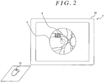
- the region designator 2 exemplarily shown in Fig. 2 has a monitor 20, such as a liquid crystal display, and a monitor drive portion (not shown) through which the fundus image A and the perimetry result image of the examinee (not shown) are displayed on the monitor 20, and an input portion 21 for designating the inspection region B on a screen of the monitor 20.
- the input portion 21 exemplarily shown in Fig. 2 is a mouse, but may be a stylus pen, or the other well-known input device.
- the inspection region B exemplarily shown in Fig.2 is a rectangular shape, but may have the other shape, such as a circle or an optional shape.
- the region on which the perimetry is expected (the inspection region) varies among patients. For instance, rather wider region may be inspected for some patients (the examinees) (for instance, see B1 of Fig.3(a) ), and it may be sufficient to inspect only the extremely narrow region for the other patients (see B2 and B3 of Fig. 3 (b), (c) ). If the inspection region is wide, it is difficult for the examinee to predict the stimulus presentation spot, thereby obtaining the correct inspection.
- the region determinator 3 determines the inspection region B2 and the spaced region C2 as the stimulus presentation region E2, and if the occupancy ratio is a predetermined standard value or higher ("the first state” hereinafter), the region determinator 3 determines the inspection region as the stimulus presentation region.
- the region determinator 3 in the invention determines the inspection region B1 as the stimulus presentation region E1 in the case where the occupancy ratio is a predetermined standard value or higher (the first state) as exemplarily shown in Fig.3(a) , determines both regions, the regions separated in an up/down direction, an oblique direction and a right/left direction from the inspection regions B2 and B3 (the spaced regions), and the inspection regions B2 and B3 as the stimulus presentation regions E2 and E3 in the case where the occupancy ratio is lower than a predetermined standard value (the second state) as exemplarily shown in Fig.3(b) and (c) .
- the stimulus presentator 6 presents the stimuli on the inspection region B in the case of the first state, and on both the spaced region C and the inspection region B in the case of the second state.
- a predetermined standard value is 60%, 70% or so of the designation image A (that is, the area of the ocular fundus) in the area or the maximum length (that is, the diameter of the designation image A that is almost a circle), and is the value with which the precision of the perimetry is expected to be similar to the case where the perimetry is conducted while the stimuli are presented to the whole visual field.
- the examinee In the case of the first state (that is, the case where the occupancy ratio is a predetermined standard value or higher), the examinee is difficult to predict the stimulus presentation spot since the inspection region itself is sufficiently wide, thereby obtaining the correct inspection result that does not receive the influence of the examinee's prediction.
- the second state that is, the occupation ratio is lower than a predetermined standard value
- the stimuli are presented also to the spot spaced from the inspection region B (that is, the spaced region C) in addition to the inspection region B, so that the examinee is difficult to predict the stimulus presentation spot, thereby obtaining the correct result that does not receive the influence of the examinee's prediction.
- the stimuli are presented to both the inspection region B and the spaced region C under the condition lower than the upper limit condition (details are mentioned later).
- there is one spaced region C in order to shorten the inspection time but two or more spaced regions may be provided within the bounds of the invention.
- the region determinator 3 may not include the spaced region C in the stimulus presentation region E.
- the region determinator 3 may compare one of the area and the length of the inspection region with a predetermined standard value.
- the region determinator 3 may judge whether "the area" of the inspection region is a predetermined standard value or higher, or lower in a case where the dimension ratio of the length and the width of the inspection region is close to 1 (one) (that is, the dimensions of the length and width are almost equal), and may judge whether "the maximum length of the inspection region” is a predetermined standard value or higher, or lower in a case where the dimension ratio of the length and the width of the inspection region is extremely different.
- the region determinator 3 determines the stimulus presentation spots so that "the total number of the stimulus presentation spots (P 1 , %) in the inspection region (see B2 of Fig. 4 )" is more than "the total number of the stimulus presentation spots (P 1 ' , ...) in the spaced region (C2)" in the case of the second state.
- the total number of the stimulus presentation spots is 100 spots, for instance, the total number of the stimulus presentation spots in the inspection region B may be 70 spots and the total number of the stimulus presentation spots in the spaced region C may be 30 spots. In such a case, it is possible to inspect the inspection region B in detail even if the inspection time is short, and to obtain the inspection result with high precision.
- the spaced region C may be provided at the position symmetric in the up/down direction or the right/left direction with the inspection region B, or at the position targeted for the inspection region B on the basis of a center of a retina G (that is, the center of fovea), and the farther away from the inspection region B, the better.
- the space region C2 is set at the position symmetric with the inspection region B in the up/down direction on the basis of the horizontal base line HL (the horizontal line including a center of a retina G in the fundus image A) in a case where it is in the second state and the inspection region B2 is on the position spaced from the horizontal base line HL, as exemplarily shown in Fig.4 .
- the total number of the stimulus presentation spots in the inspection region B2 may be more than "the total number of the stimulus presentation spots in the spaced region C2".
- the stimulus presentation spots (P 1 , ...) in the inspection region B2 is referred to as "a main stimulus presentation spot”
- the stimulus presentation spots (P 1 ' , ...) in the spaced region C2 is referred to as " a sub stimulus presentation spot”
- one main stimulus presentation spot (P 1 , for instance) may always be set at the position symmetric with the position of the sub stimulus presentation spot (for instance, P 1 ') with respect to the horizontal base line HL.
- the stimulus presented to the main stimulus presentation spot and “the stimulus presented to the sub stimulus presentation spot” may have the same size and brightness.
- the gap of the symmetry in the up/down direction can be found, thereby easily finding ocular diseases, such as the glaucoma.
- the spaced region may be set at the position excluding one symmetric with respect to the horizontal base line HL (the position apart in the up/down direction, the lateral direction or the oblique direction).
- the inspection region B3 and the spaced region C3 may be the stimulus presentation regions, or the inspection region B3, the spaced region C3 and the symmetric region D3 may be the stimulus presentation regions.
- the inspection region B3, the spaced region C3 and the symmetric region D3 are the stimulus presentation regions and the stimulus presentation spot in the inspection region B3 is referred to as "the main presentation spot” and the stimulus presentation spot in the symmetric region D3 is referred to as "the sub stimulus presentation spot”
- one main stimulus presentation spot may always be set at the position symmetric with the position of the sub stimulus presentation spot on the basis of the horizontal base line HL.
- the stimulus presented to the main stimulus presentation spot and “the stimulus presented to the sub presentation spot” may have the same size and brightness.
- the gap of the symmetry in the up/down direction can be found, thereby easily finding ocular diseases, such as the glaucoma.
- the stimuli may be presented in such a state that "the total number of the stimulus presentation spots in the inspection region B3" > "the total number of the stimulus presentation spots in the symmetric region D3" > “the total number of the stimulus presentation spots in the spaced region C3".
- the stimuli may be presented in such a state that stimulus presentation density in the inspection region B3" > “the stimulus presentation density in the symmetric region D3 (if the inspection region B3 overlaps the symmetric region D3 as exemplarily shown in Fig.3(c) , the spot that does not overlap the inspection region B3 in the symmetric region D3) > "the stimulus presentation density in the spaced region C3".
- the perimetry is done on the designated region as the present invention since ocular diseases, such as the glaucoma, exists in such a region with a higher possibility, so that it is necessary to enhance the precision of the inspection in comparison with a normal perimetry (that is, the inspection which is done on whole visual field with no region designation), and necessary to highly keep the examinee's concentration during the inspection.
- ocular diseases such as the glaucoma
- the upper limit condition setter 4 may be provided, that sets “upper limit for conducting the perimetry ("the upper limit time” hereinafter) Tmax” or “total number of the stimulus presentation spots (both upper limit time and the total number are referred to as “the upper limit condition” hereinafter), so that the position determinator 5 determines the number of times to present the stimuli and the stimulus presentation spot in order to finish the perimetry on a condition lower than the upper limit condition (that is, the time shorter than the upper limit time Tmax or the stimulus presentation spots the number of which is smaller than the above-mentioned total number).
- the examinee knows a predetermined required time till the finish of the perimetry, and is able to highly keep his (or her) concentration in comparison with the case where required predetermined time is not known. At the result, it is improve the precision of the inspection.
- the upper limit condition setter 4 There are various kinds of the upper limit condition setter 4, and these are a graphical user interface on the screen (and a pointing device for setting the upper limit condition on the interface), and some kind of switch attached to the perimeter, such as a dial switch, for instance.
- Such an upper limit condition setter 4 sets any one of "the upper limit time Tmax" and "the total number of the stimulus presentation spots".
- it has a function to set only the upper limit time Tmax, a function to set only the total number of the stimulus presentation spots, and a function to set both "the upper limit time Tmax" and "the total number of the stimulus presentation spots, and the examiner is able to select it as needed.
- the position determinator 5 determines the total number N of the stimulus presentation spots and the positions in the stimulus presentation region E when the upper limit condition setter 4 sets the upper limit time Tmax, and determines the position of each stimulus presentation spot when the upper limit condition setter 4 sets the total number of the stimulus presentation spots.
- the stimulus presentator 6 presents the stimuli two times or more, gradually changing the brightness of the stimulus at each stimulus presentation spot (the details are mentioned hereinafter), and the position determinator 5 may determine the number of times to present the stimuli at each stimulus presentation spot (that is, the number of times to present the stimuli at each presentation spot, gradually changing the brightness, four times in the example as shown in Fig.5 (1) to (4)).
- the stimulus presentator 6 In order to finish the perimetry within the upper limit time as mentioned before, if the upper limit time that is set is Tmax and approximate time necessary for the inspection for one stimulus presentation spot is t, the total number N of the stimulus presentation spots is obtained with Tmax ⁇ t.
- the stimulus presentator 6 sometimes presents the stimuli onto the spaced region C and the symmetric region D in addition to the inspection region B, and it is necessary for the position determinator 5 to determine the number N 1 of the stimulus presentation spots in the inspection region B, the number N 2 of the stimulus presentation spots in the spaced region C and the number N 3 of the stimulus presentation spots in the symmetric region D so as to be N 1 +N 2 +N 3 ⁇ N.
- the position determinator 5 may determine at least one of "the stimulus presentation spots in the past perimetry (the positions onto which the stimuli were presented) as "the stimulus presentation spots in this time of the perimetry (the positions onto which the stimuli to be presented). By doing so, the result of the past perimetry and the result of this time of the perimetry can be compared with each other in the same stimulus presentation spot, thereby grasping the progress of the ocular disease.
- the perimetry images are stored, adding identification information of the patients, thereby comparing the perimetry results as mentioned before through the identification information.
- the region designator 2 displays the perimetry result image, highlighting the spots which perimetry result was bad (the bad spots rather than a predetermined standard) that are the stimulus presentation spots in the past perimetry (the positions onto which the stimuli were actually presented). By doing so, it is easily grasp the regions to be inspected again.
- the position determinator 5 may determine "the spots which perimetry result was bad in the stimulus presentation spots in the past perimetry (the spots on which the stimuli were presented)" as "the stimulus presentation spots in this time of the perimetry (the spots on which the stimuli are to be presented)".
- the stimulus presentator 6 is configured to present the stimuli, gradually changing their brightness at the respective stimulus presentation spots twice or more and to conduct a so-called threshold inspection.
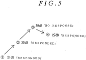
- Fig.5 is a conceptual diagram that shows a way of the threshold inspection at one stimulus presentation spot. In the instance as shown in Fig.5 , the stimuli are presented four times in order of (1) ⁇ (2) ⁇ (3) ⁇ (4), and the brightness of the respective stimuli are gradually changed in order of 21dB ⁇ 25dB(rather darker than 21dB) ⁇ 29dB (rather darker than 25dB) ⁇ 27dB (rather brighter than 29dB).
- the stimulus presentator 6 may be configured to have a projection optical system 60 for projecting the stimuli Q and the visual field dome (projection member) 61, but is not limited to such a configuration shown in Fig. 6 . Any configuration may be taken as long as the stimuli are presented in the visual field of the examinee. For instance, two or more LED may be located and may be selectively lighted.
- the projection member 61 as shown in Fig.6 is in the shape of a hemisphere dome (visual field dome), but is not limited to such a configuration, and may have a curve surface excluding the hemispheric surface, or a flat surface.
- the stimulus presentator 6 may be configured to present the stimuli so as to make "the stimulus presented onto the spaced region C" bigger than and/or brighter than "the stimulus presented onto the spaced region C".
- the examinee is easy to perceive the stimuli that are presented onto the spaced region C, it is possible to prevent the examinee's concentration from being poured onto only the inspection region B, and obtain the correct inspection result that does not receive the influence of the examinee's prediction.
- the inspection region B and the spaced region C are located symmetric in the up/down direction on the basis of the horizontal standard line HL, the stimuli having the same size and brightness may be presented thereon.
- the gap of the symmetry in the up/down direction can be found, thereby easily finding ocular diseases, such as the glaucoma.
- a well-known mechanism such as a push switch, is used for the above-mentioned operation portion 7.
- the perimeter 1 presents the stimuli onto two or more spots in the stimulus presentation regions E1 to E3, and presents the stimuli twice or more, receiving the responses from the examinee, not once for one spot. If the response from the examinee is late, then, it takes a longer time for the inspection, so that the inspection may not finish within the upper limit time Tmax.
- the perimeter 1 has a state confirmor 9, a finish time predictor 10 and a stimulus controller 11.
- the state confirmor 9 confirms the progress state of the inspection during the perimetry based upon signals from the stimulus presentator 6 and the operation portion 7.
- the finish time predictor 10 predicts whether the inspection finishes within the upper limit time Tmax for all stimulus presentation spots based upon the progress state confirmed by the state confirmor 9.
- the stimulus controller 11 controls the stimulus presentator 6 not to present the stimulus onto a part of the stimulus presentation spots if the finish time predictor 10 predicted the perimetry does not finish within the upper limit time Tmax for all stimulus presentation spots.
- the inspection in the present invention is conducted, receiving the responses from the examinee, and it may take a longer time for the perimetry on each stimulus presentation spot.
- the finish time predictor 10 may have a time measurer for measuring a passage time from the start of the perimetry.
- the stimulus presentation may be omitted in such a way that when the stimuli are presented to one stimulus presentation spot, gradually changing the brightness, the number of the stimulus presentation is reduced, or all stimulus presentation is omitted to some stimulus presentation spot (the spot to which the stimulus presentation is scheduled).
- the latter method that is, the method of omitting all stimulus presentation to some stimulus presentation spot
- the latter method that is, the method of omitting all stimulus presentation to some stimulus presentation spot
- the above-mentioned "a part of stimulus presentation spots (that is, the spots that are omitted to be presented by the stimulus controller 11)" is not ones in the inspection region B, but ones in the spaced region C.
- the stimulus controller 11 may control the stimulus presentator 6 not to present the stimuli onto a part of the stimulus presentation spots in the spaced region C. By doing so, the stimulus presentation is not omitted on the inspection region B, thereby well keeping the precision of the inspection in the inspection region B.
- the finish time predictor 10 obtains from respective data, the upper limit time Tmax that is set, already passed time T 0 , number N a of the stimulus presentation spots on which stimulus presentation does not finish (the number obtained from the information from the state confirmor 9) and approximate time required for the inspection on one stimulus presentation spot, the time left for the inspection "Tmax - T 0 " and time necessary for remaining inspection "N a ⁇ t", and compares both times.
- the above-mentioned time t (that is, the approximate time necessary for the inspection on one stimulus presentation spot) is obtained from the respective data, "the number n of the stimulus presentation on each stimulus presentation spot (the number of times that is expected)", “the expected response time ⁇ t1 of the examinee (the time from the presentation of the stimulus till the response from the examinee)” and “the time ⁇ t2 till the next stimulus presentation if no response is received from the examinee (the time that is set).
- the position determinator 5 is configured to give the respective stimulus presentation spots priority (the orders from the view of the importance of the inspection), and the stimulus controller 11 omits the stimulus presentation on the spot having the lower priority (the stimulus presentation spot).
- the stimulus controller 11 may conduct the stimulus presentation that has been omitted at this time.
Landscapes
- Health & Medical Sciences (AREA)
- Life Sciences & Earth Sciences (AREA)
- Engineering & Computer Science (AREA)
- Medical Informatics (AREA)
- Surgery (AREA)
- Biophysics (AREA)
- Biomedical Technology (AREA)
- Heart & Thoracic Surgery (AREA)
- Physics & Mathematics (AREA)
- Molecular Biology (AREA)
- Ophthalmology & Optometry (AREA)
- Animal Behavior & Ethology (AREA)
- General Health & Medical Sciences (AREA)
- Public Health (AREA)
- Veterinary Medicine (AREA)
- Signal Processing (AREA)
- Eye Examination Apparatus (AREA)
Abstract
Description
- The invention relates to a perimeter for inspecting a visual field of an examinee in a state that the examinee fixates a predetermined fixation point, and especially to the perimeter that is configured to designate a region that is expected to be inspected.
- The perimeter has been used in order to find ocular diseases, such as the glaucoma. A conventional problem in such a perimeter is that it takes a longer time to conduct a perimetry on the whole visual field that results in heavy burden on a patient.
- Then, such a perimeter that the region on which the perimetry is conducted is designated on a fundus image, and the perimetry is conducted on such a designated region has been proposed (see Patent-
related documents -
Fig.7 is a typical view that shows an example of a way of designating the region, a reference number A denotes the fundus image, and B denotes the designated region. - According to such a perimeter, it is possible to designate only the region on which the perimetry is to be conducted and conduct the perimetry on only such a region, and to shorten the inspection time and reduce the burden on examinees and examiners, and to effectively detect the disorder of the visual field in comparison with a case where the perimetry is conducted on the whole visual field.
-
- [Patent-related document 1]: Japanese Patent Application Publication No.
H06-054804 - [Patent-related document 2]: Japanese Patent Application Publication No.
2000-262472 - There are such anxieties when conducting the perimetry as mentioned before that patients (the examinees) predict a rough region to which the stimuli are presented and pay attentions to only such a region, and for this reason, it is not possible to obtain the correct inspection result under the influence.
- An object of the invention is to provide the perimeter for solving the above-mentioned problems.
- A first aspect of the invention is a perimeter (1) that exemplarily shown in
Fig.1 for inspecting a visual field of an examinee in such a state the examinee fixates a predetermined fixation point, comprising: - a region designator (2) that is configured to display an image that shows a past perimetry result or a fundus image (both images are collectively referred to as "the designation image" hereinafter, see a reference number A of
Fig. 3 (b) andFig.4 ), and to designate a region on which the perimetry is expected to be done ("the inspection region" hereinafter, see B2 ofFig. 3 (b) andFig.4 ) on the designation image (A); - a region determinator (3) that determines a region to which the stimuli are presented ("the stimulus presentation region" hereinafter, see E2 of
Fig.3(b) ) based upon the designated inspection region (B2); - a position determinator (5) that determines a position of a spot onto which the stimulus is presented in the stimulus presentation region (E2) ("the stimulus presentation spot" hereinafter);
- a stimulus presentator (6) that presents the stimulus with a predetermined brightness to each position determined through the position determinator (5) in order;
- an operation portion (7) to be operated by the examinee who perceived the presented stimulus; and
- a result judger (8) that judges the inspection result based upon signals from the stimulus presentator (6) and the operation portion (7);
- A second aspect of the invention is the perimeter (1), wherein the stimulus presentator (6) is configured to present the stimuli to each stimulus presentation spot, gradually changing their brightness twice or more.
- A third aspect of the invention is a perimeter (1), wherein the position determinator (5) determines the stimulus presentation spots (P1, ..., P1' , ...) such that "the total number of the stimulus presentation spots (P1, ...) in the inspection region (see B2 of
Fig.4 )" is more than "the total number of the stimulus presentation spots (P1' , ...) in the spaced region (C2)". - A fourth aspect of the invention is the perimeter (1), wherein the stimulus presentator (6) is configured such that "the stimuli presented to the spaced region (C2)" are presented so as to be bigger and/or brighter than "the stimuli presented to the inspection region (B2)".
- A fifth aspect of the invention is the perimeter (1), wherein if a ratio regarding its area and length that the inspection region (B2) occupied the designation image (A) ("the occupancy ratio" hereinafter) is lower than a predetermined standard value ("the second state" hereinafter), the region determinator (3) determines the inspection region (B2) and the spaced region (C2) as the stimulus presentation region (E2), and if the occupancy ratio is a predetermined standard value or higher ("the first state" hereinafter, see
Fig.3(a) ), the region determinator (3) determines the inspection region (B1) as the stimulus presentation region (E1), and the stimulus presentator (6) presents the stimuli onto the inspection region (B1) in a case of the first state, and onto both the space region (C2) and the inspection region (B2) in a case of the second state. - A sixth aspect of the invention is the perimeter (1), wherein if there are two or more inspection regions that are designated by the region designator (2) and these inspection regions are separated from each other, the region determinator (3) does not include the spaced region in the stimulus presentation region.
- A seventh aspect of the invention is the perimeter (1), wherein the region designator (2) is configured to display the perimetry result image and to designate the inspection region (B2) on the perimetry result image, and the position determinator (5) is configured to determine at least one of the stimulus presentation spots in the past perimetry as the stimulus presentation spot at this time of the perimetry.
- The number in parentheses shows the corresponding element in the drawings for the sake of convenience, accordingly, the descriptions are not restricted and bound by the descriptions on the drawings.
- According to the 1st, 2nd, 5th and 6th aspects of the invention, the stimuli are presented also to the spaced region spaced from the inspection region in addition to the inspection region designated by the region designator, so that it is difficult for the examinee to predict the stimulus presentation spot and it is possible to obtain the correct inspection result that does not receive the examinee's prediction.
- According to the 3rd aspect of the invention, it is possible to inspect the inspection region in detail even if the inspection time is short, and to obtain the inspection result with a high accuracy.
- According to the 4th aspect of the invention, it is easy for the examinee to perceive the stimuli that are presented onto the spaced region, and possible to restrain that the examinee' s concentration is turned only to the inspection region, and possible to obtain the correct inspection result that does not receive the examinee's prediction.
- According to the 7th aspect of the invention, it is possible to compare the past perimetry result and at this time of the perimetry result at the same stimulus presentation spot with each other, and to grasp the progress of the ocular disease.
-
- [
Fig.1] Fig.1 is a block diagram that shows an example of a structure of a perimeter according to the present invention. - [
Fig.2] Fig.2 is a typical view that shows an example of a structure of a region designator. -
[Fig.3] Fig.3 (a) through (c) are typical views exemplarily show positions of an inspection region and the like. - [
Fig.4] Fig.4 is a typical view that shows an example of stimulus presentation spots in the inspection region and a spaced region. - [
Fig.5] Fig.5 is a conceptual view that shows a way of a threshold inspection in one stimulus presentation spot. - [
Fig.6] Fig.6 is a perspective view that shows an example of a structure of the perimeter. - [
Fig.7] Fig.7 is a typical view that schematically shows an example of a way of designating a region (inspection region) (conventional example). - Embodiments of the invention are now explained, referring to appended figures
Figs.1 through 6 . - A perimeter according to the invention that exemplarily shown with a
reference number 1 ofFig. 1 , is for testing a visual field of an examinee in a state that he (or she) fixates a predetermined fixation point, such as a central position of a visual field dome 61 exemplarily shown inFig. 6 ), and has aregion designator 2, aregion determinator 3, aposition determinator 5, astimulus presentator 6, anoperation portion 7 and aresult judger 8. Theregion designator 2 displays "an image that shows a result of a past perimetry ("the perimetry result image" hereinafter) " or "a normal fundus image that does not show the result of the perimetry (see a reference number A ofFig.2 ,Fig.3(a) to (c) andFig.4 . The perimetry result image and the fundus image are referred to as "the designation image" hereinafter.), and designates a region on which the perimetry is to be done (see a reference number B ofFig.2 and reference numbers B1 to B3 ofFig. 3 (a) to (c) andFig. 4 . "the inspection region" hereinafter) on the designation image A. Theregion determinator 3 determines the region on which a stimulus is actually presented (see reference numbers E1 to E3 ofFig.3 (a) to (c) . "the stimulus presentation region" hereinafter) based upon the designated inspection regions B, B1 to B3. Theposition determinator 5 determines at least a spot onto which each stimulus is presented ("the stimulus presentation spot" hereinafter) in the stimulus presentation region at least. Thestimulus presentator 6 presents the stimuli having a predetermined brightness in order at each position that is determined through theposition determinator 5. Theoperation portion 7 is operated by the examinee who perceives the presented stimulus. The result judger 8 judges the perimetry result based upon signals from thestimulus presentator 6 and theoperation portion 7. As exemplarily shown inFig. 3 (b) andFig.4 , theregion determinator 3 is configured so as to determine both regions, the regions C2 separated in an up/down direction, an oblique direction and a right/left direction from the inspection region B2 ("the spaced region" hereinafter) and the inspection region B2 as the stimulus presentation region E2, and thestimulus presentator 6 is configured so as to present the stimuli onto both regions, the spaced region C2 and the inspection region B2. - If it is necessary to distinguish the inspection regions by their shapes and positions, reference numbers "B1, "B2" and "B3" are used, and when such a distinction is not necessary, only the reference number "B" is used in the following explanation. This is similar regarding the stimulus presentation region, and if it is necessary to distinguish the stimulus presentation regions by their shapes and positions, reference numbers "E1, "E2" and "E3" are used, and when such a distinction is not necessary, only the reference number "E" is used. Furthermore, it is similar regarding the spaced region, and reference numbers "C2" and "C3" are used if it is not necessary to distinguish the stimulus presentation regions by their shapes and positions, and only the reference number "C" is used when such a distinction is not necessary.
- According to the invention, the stimuli are presented to the region C2 spaced from the inspection region B2 in addition to the inspection region B2 that is designated by the
region designator 2, so that it is difficult for the examinee to predict the stimulus presentation spot and possible to obtain a correct inspection result that does not receive the influence of the examinee's prediction. - Subsequently, respective elements comprising the
perimeter 1 are now explained. - Preferably, the
region designator 2 exemplarily shown inFig. 2 has amonitor 20, such as a liquid crystal display, and a monitor drive portion (not shown) through which the fundus image A and the perimetry result image of the examinee (not shown) are displayed on themonitor 20, and aninput portion 21 for designating the inspection region B on a screen of themonitor 20. Theinput portion 21 exemplarily shown inFig. 2 is a mouse, but may be a stylus pen, or the other well-known input device. The inspection region B exemplarily shown inFig.2 is a rectangular shape, but may have the other shape, such as a circle or an optional shape. - The region on which the perimetry is expected (the inspection region) varies among patients. For instance, rather wider region may be inspected for some patients (the examinees) (for instance, see B1 of
Fig.3(a) ), and it may be sufficient to inspect only the extremely narrow region for the other patients (see B2 and B3 ofFig. 3 (b), (c) ). If the inspection region is wide, it is difficult for the examinee to predict the stimulus presentation spot, thereby obtaining the correct inspection. Preferably, if the ratio that the inspection region B2 occupied the designation image A (that is, in the area of the fundus) that is the ratio regarding its area and length and is referred to as "occupancy ratio" hereinafter is lower than a predetermined standard value ("the second state" hereinafter), theregion determinator 3 determines the inspection region B2 and the spaced region C2 as the stimulus presentation region E2, and if the occupancy ratio is a predetermined standard value or higher ("the first state" hereinafter), theregion determinator 3 determines the inspection region as the stimulus presentation region. That is, theregion determinator 3 in the invention determines the inspection region B1 as the stimulus presentation region E1 in the case where the occupancy ratio is a predetermined standard value or higher (the first state) as exemplarily shown inFig.3(a) , determines both regions, the regions separated in an up/down direction, an oblique direction and a right/left direction from the inspection regions B2 and B3 (the spaced regions), and the inspection regions B2 and B3 as the stimulus presentation regions E2 and E3 in the case where the occupancy ratio is lower than a predetermined standard value (the second state) as exemplarily shown inFig.3(b) and (c) . Preferably, thestimulus presentator 6 presents the stimuli on the inspection region B in the case of the first state, and on both the spaced region C and the inspection region B in the case of the second state. In this case, "a predetermined standard value" is 60%, 70% or so of the designation image A (that is, the area of the ocular fundus) in the area or the maximum length (that is, the diameter of the designation image A that is almost a circle), and is the value with which the precision of the perimetry is expected to be similar to the case where the perimetry is conducted while the stimuli are presented to the whole visual field. In the case of the first state (that is, the case where the occupancy ratio is a predetermined standard value or higher), the examinee is difficult to predict the stimulus presentation spot since the inspection region itself is sufficiently wide, thereby obtaining the correct inspection result that does not receive the influence of the examinee's prediction. In a case of the second state (that is, the occupation ratio is lower than a predetermined standard value), the stimuli are presented also to the spot spaced from the inspection region B (that is, the spaced region C) in addition to the inspection region B, so that the examinee is difficult to predict the stimulus presentation spot, thereby obtaining the correct result that does not receive the influence of the examinee's prediction. In the case where an upperlimit condition setter 4 is provided as mentioned hereinafter and it is in the second state, the stimuli are presented to both the inspection region B and the spaced region C under the condition lower than the upper limit condition (details are mentioned later). Preferably, there is one spaced region C in order to shorten the inspection time, but two or more spaced regions may be provided within the bounds of the invention. Furthermore, if two or more inspection regions B are designated by the region designator and spaced from each other, theregion determinator 3 may not include the spaced region C in the stimulus presentation region E. Besides, theregion determinator 3 may compare one of the area and the length of the inspection region with a predetermined standard value. Alternatively, theregion determinator 3 may judge whether "the area" of the inspection region is a predetermined standard value or higher, or lower in a case where the dimension ratio of the length and the width of the inspection region is close to 1 (one) (that is, the dimensions of the length and width are almost equal), and may judge whether "the maximum length of the inspection region" is a predetermined standard value or higher, or lower in a case where the dimension ratio of the length and the width of the inspection region is extremely different. - Preferably, the
region determinator 3 determines the stimulus presentation spots so that "the total number of the stimulus presentation spots (P1, ...) in the inspection region (see B2 ofFig. 4 )" is more than "the total number of the stimulus presentation spots (P1' , ...) in the spaced region (C2)" in the case of the second state. In a case where the total number of the stimulus presentation spots is 100 spots, for instance, the total number of the stimulus presentation spots in the inspection region B may be 70 spots and the total number of the stimulus presentation spots in the spaced region C may be 30 spots. In such a case, it is possible to inspect the inspection region B in detail even if the inspection time is short, and to obtain the inspection result with high precision. - On the other hand, the spaced region C may be provided at the position symmetric in the up/down direction or the right/left direction with the inspection region B, or at the position targeted for the inspection region B on the basis of a center of a retina G (that is, the center of fovea), and the farther away from the inspection region B, the better. Preferably, the space region C2 is set at the position symmetric with the inspection region B in the up/down direction on the basis of the horizontal base line HL (the horizontal line including a center of a retina G in the fundus image A) in a case where it is in the second state and the inspection region B2 is on the position spaced from the horizontal base line HL, as exemplarily shown in
Fig.4 . In such a case also, "the total number of the stimulus presentation spots in the inspection region B2" may be more than "the total number of the stimulus presentation spots in the spaced region C2". If the stimulus presentation spots (P1, ...) in the inspection region B2 is referred to as "a main stimulus presentation spot", and the stimulus presentation spots (P1' , ...) in the spaced region C2 is referred to as " a sub stimulus presentation spot", one main stimulus presentation spot (P1, for instance) may always be set at the position symmetric with the position of the sub stimulus presentation spot (for instance, P1') with respect to the horizontal base line HL. Besides, "the stimulus presented to the main stimulus presentation spot" and "the stimulus presented to the sub stimulus presentation spot" may have the same size and brightness. When comparing the inspection results of the main stimulus presentation spot P1, ... and the sub stimulus presentation spot P1' , ... that are symmetric in the up/down direction with each other in the above-mentioned case, the gap of the symmetry in the up/down direction can be found, thereby easily finding ocular diseases, such as the glaucoma. - On the contrary, in a case where it is in the second state, and the inspection region B3 includes the horizontal base line HL or approaches the horizontal base line HL, so that the region symmetric with the inspection region B3 on the basis of the horizontal base line HL ("the symmetric region" hereinafter) is not spaced from the inspection region B3 as exemplarily shown in
Fig. 3(c) , the spaced region (see C3) may be set at the position excluding one symmetric with respect to the horizontal base line HL (the position apart in the up/down direction, the lateral direction or the oblique direction). In such a case, the inspection region B3 and the spaced region C3 may be the stimulus presentation regions, or the inspection region B3, the spaced region C3 and the symmetric region D3 may be the stimulus presentation regions. In the latter case (that is, in the case where the inspection region B3, the spaced region C3 and the symmetric region D3 are the stimulus presentation regions and the stimulus presentation spot in the inspection region B3 is referred to as "the main presentation spot" and the stimulus presentation spot in the symmetric region D3 is referred to as "the sub stimulus presentation spot", one main stimulus presentation spot may always be set at the position symmetric with the position of the sub stimulus presentation spot on the basis of the horizontal base line HL. Besides, "the stimulus presented to the main stimulus presentation spot" and "the stimulus presented to the sub presentation spot" may have the same size and brightness. In such a case, it is difficult for the examinee to predict the stimulus presentation spot by presenting the stimuli on the space region C3, thereby obtaining the correct inspection result that does not receive the influence of the examinee's prediction. At the same time, when comparing the inspection results of the main stimulus presentation spot and the sub stimulus presentation spot that are symmetric in the up/down direction with each other, the gap of the symmetry in the up/down direction can be found, thereby easily finding ocular diseases, such as the glaucoma. In this case, the stimuli may be presented in such a state that "the total number of the stimulus presentation spots in the inspection region B3" > "the total number of the stimulus presentation spots in the symmetric region D3" > "the total number of the stimulus presentation spots in the spaced region C3". Besides, the stimuli may be presented in such a state that stimulus presentation density in the inspection region B3" > "the stimulus presentation density in the symmetric region D3 (if the inspection region B3 overlaps the symmetric region D3 as exemplarily shown inFig.3(c) , the spot that does not overlap the inspection region B3 in the symmetric region D3) > "the stimulus presentation density in the spaced region C3". - The perimetry is done on the designated region as the present invention since ocular diseases, such as the glaucoma, exists in such a region with a higher possibility, so that it is necessary to enhance the precision of the inspection in comparison with a normal perimetry (that is, the inspection which is done on whole visual field with no region designation), and necessary to highly keep the examinee's concentration during the inspection. Then, the upper
limit condition setter 4 may be provided, that sets "upper limit for conducting the perimetry ("the upper limit time" hereinafter) Tmax" or "total number of the stimulus presentation spots (both upper limit time and the total number are referred to as "the upper limit condition" hereinafter), so that theposition determinator 5 determines the number of times to present the stimuli and the stimulus presentation spot in order to finish the perimetry on a condition lower than the upper limit condition (that is, the time shorter than the upper limit time Tmax or the stimulus presentation spots the number of which is smaller than the above-mentioned total number). By doing so, the examinee knows a predetermined required time till the finish of the perimetry, and is able to highly keep his (or her) concentration in comparison with the case where required predetermined time is not known. At the result, it is improve the precision of the inspection. There are various kinds of the upperlimit condition setter 4, and these are a graphical user interface on the screen (and a pointing device for setting the upper limit condition on the interface), and some kind of switch attached to the perimeter, such as a dial switch, for instance. Such an upperlimit condition setter 4 sets any one of "the upper limit time Tmax" and "the total number of the stimulus presentation spots". Concretely speaking, it has a function to set only the upper limit time Tmax, a function to set only the total number of the stimulus presentation spots, and a function to set both "the upper limit time Tmax" and "the total number of the stimulus presentation spots, and the examiner is able to select it as needed. - Preferably, the
position determinator 5 determines the total number N of the stimulus presentation spots and the positions in the stimulus presentation region E when the upperlimit condition setter 4 sets the upper limit time Tmax, and determines the position of each stimulus presentation spot when the upperlimit condition setter 4 sets the total number of the stimulus presentation spots. And, thestimulus presentator 6 presents the stimuli two times or more, gradually changing the brightness of the stimulus at each stimulus presentation spot (the details are mentioned hereinafter), and theposition determinator 5 may determine the number of times to present the stimuli at each stimulus presentation spot (that is, the number of times to present the stimuli at each presentation spot, gradually changing the brightness, four times in the example as shown inFig.5 (1) to (4)). In order to finish the perimetry within the upper limit time as mentioned before, if the upper limit time that is set is Tmax and approximate time necessary for the inspection for one stimulus presentation spot is t, the total number N of the stimulus presentation spots is obtained with Tmax ÷ t. As mentioned before, thestimulus presentator 6 sometimes presents the stimuli onto the spaced region C and the symmetric region D in addition to the inspection region B, and it is necessary for theposition determinator 5 to determine the number N1 of the stimulus presentation spots in the inspection region B, the number N2 of the stimulus presentation spots in the spaced region C and the number N3 of the stimulus presentation spots in the symmetric region D so as to be N1 +N2+N3 ≦N. - On the other hand, when the
region designator 2 is configured to display the perimetry result image and designate the inspection region based upon the perimetry result image, theposition determinator 5 may determine at least one of "the stimulus presentation spots in the past perimetry (the positions onto which the stimuli were presented) as "the stimulus presentation spots in this time of the perimetry (the positions onto which the stimuli to be presented). By doing so, the result of the past perimetry and the result of this time of the perimetry can be compared with each other in the same stimulus presentation spot, thereby grasping the progress of the ocular disease. Preferably, the perimetry images are stored, adding identification information of the patients, thereby comparing the perimetry results as mentioned before through the identification information. Preferably, theregion designator 2 displays the perimetry result image, highlighting the spots which perimetry result was bad (the bad spots rather than a predetermined standard) that are the stimulus presentation spots in the past perimetry (the positions onto which the stimuli were actually presented). By doing so, it is easily grasp the regions to be inspected again. Furthermore, theposition determinator 5 may determine "the spots which perimetry result was bad in the stimulus presentation spots in the past perimetry (the spots on which the stimuli were presented)" as "the stimulus presentation spots in this time of the perimetry (the spots on which the stimuli are to be presented)". - The
stimulus presentator 6 is configured to present the stimuli, gradually changing their brightness at the respective stimulus presentation spots twice or more and to conduct a so-called threshold inspection.Fig.5 is a conceptual diagram that shows a way of the threshold inspection at one stimulus presentation spot. In the instance as shown inFig.5 , the stimuli are presented four times in order of (1)→ (2)→ (3) → (4), and the brightness of the respective stimuli are gradually changed in order of 21dB →25dB(rather darker than 21dB)→ 29dB (rather darker than 25dB)→ 27dB (rather brighter than 29dB). Responses through theoperation portion 7 from the examinee are respectively "responded", "responded", "no response" "responded" in the stimulus presentation (1), (2), (3) and (4). In such a case, theresult judger 8 judges the sensitivity of the retina in this spot (the stimulus presentation spot) is 27dB. - As exemplarily shown in
Fig.6 , thestimulus presentator 6 may be configured to have a projectionoptical system 60 for projecting the stimuli Q and the visual field dome (projection member) 61, but is not limited to such a configuration shown inFig. 6 . Any configuration may be taken as long as the stimuli are presented in the visual field of the examinee. For instance, two or more LED may be located and may be selectively lighted. The projection member 61 as shown inFig.6 is in the shape of a hemisphere dome (visual field dome), but is not limited to such a configuration, and may have a curve surface excluding the hemispheric surface, or a flat surface. - In the case of the second state, the
stimulus presentator 6 may be configured to present the stimuli so as to make "the stimulus presented onto the spaced region C" bigger than and/or brighter than "the stimulus presented onto the spaced region C". By doing so, the examinee is easy to perceive the stimuli that are presented onto the spaced region C, it is possible to prevent the examinee's concentration from being poured onto only the inspection region B, and obtain the correct inspection result that does not receive the influence of the examinee's prediction. If the inspection region B and the spaced region C are located symmetric in the up/down direction on the basis of the horizontal standard line HL, the stimuli having the same size and brightness may be presented thereon. When comparing the inspection results of the main stimulus presentation spot P1, ... and the sub stimulus presentation spot P1', ... that are symmetric in the up/down direction with each other in the above-mentioned case, the gap of the symmetry in the up/down direction can be found, thereby easily finding ocular diseases, such as the glaucoma. - Preferably, a well-known mechanism, such as a push switch, is used for the above-mentioned
operation portion 7. - The
perimeter 1 according to the present invention presents the stimuli onto two or more spots in the stimulus presentation regions E1 to E3, and presents the stimuli twice or more, receiving the responses from the examinee, not once for one spot. If the response from the examinee is late, then, it takes a longer time for the inspection, so that the inspection may not finish within the upper limit time Tmax. - Preferably, the
perimeter 1 according to the invention has astate confirmor 9, afinish time predictor 10 and astimulus controller 11. Thestate confirmor 9 confirms the progress state of the inspection during the perimetry based upon signals from thestimulus presentator 6 and theoperation portion 7. Thefinish time predictor 10 predicts whether the inspection finishes within the upper limit time Tmax for all stimulus presentation spots based upon the progress state confirmed by thestate confirmor 9. Thestimulus controller 11 controls thestimulus presentator 6 not to present the stimulus onto a part of the stimulus presentation spots if thefinish time predictor 10 predicted the perimetry does not finish within the upper limit time Tmax for all stimulus presentation spots. The inspection in the present invention is conducted, receiving the responses from the examinee, and it may take a longer time for the perimetry on each stimulus presentation spot. However, it is possible to finish the perimetry within the upper limit time Tmax by omitting a part of the stimulus presentation when providing thestate confirmor 9, thefinish time predictor 10 and thestimulus controller 11. In such a case, thefinish time predictor 10 may have a time measurer for measuring a passage time from the start of the perimetry. In this case, the stimulus presentation may be omitted in such a way that when the stimuli are presented to one stimulus presentation spot, gradually changing the brightness, the number of the stimulus presentation is reduced, or all stimulus presentation is omitted to some stimulus presentation spot (the spot to which the stimulus presentation is scheduled). When presenting the stimulus in the regions symmetric in the up/down direction in order to find the ocular disease, the latter method (that is, the method of omitting all stimulus presentation to some stimulus presentation spot) may be taken, not the former one. - Preferably, the above-mentioned "a part of stimulus presentation spots (that is, the spots that are omitted to be presented by the stimulus controller 11)" is not ones in the inspection region B, but ones in the spaced region C. When the
finish time predictor 10 predicted the inspection does not finish within the upper limit time Tmax for all the stimulus presentation spots and it is in the second state, thestimulus controller 11 may control thestimulus presentator 6 not to present the stimuli onto a part of the stimulus presentation spots in the spaced region C. By doing so, the stimulus presentation is not omitted on the inspection region B, thereby well keeping the precision of the inspection in the inspection region B. - Preferably, the
finish time predictor 10 obtains from respective data, the upper limit time Tmax that is set, already passed time T0, number Na of the stimulus presentation spots on which stimulus presentation does not finish (the number obtained from the information from the state confirmor 9) and approximate time required for the inspection on one stimulus presentation spot, the time left for the inspection "Tmax - T0" and time necessary for remaining inspection "Na × t", and compares both times. Preferably, the above-mentioned time t (that is, the approximate time necessary for the inspection on one stimulus presentation spot) is obtained from the respective data, "the number n of the stimulus presentation on each stimulus presentation spot (the number of times that is expected)", "the expected response time Δt1 of the examinee (the time from the presentation of the stimulus till the response from the examinee)" and "the time Δt2 till the next stimulus presentation if no response is received from the examinee (the time that is set). Preferably, theposition determinator 5 is configured to give the respective stimulus presentation spots priority (the orders from the view of the importance of the inspection), and thestimulus controller 11 omits the stimulus presentation on the spot having the lower priority (the stimulus presentation spot). Furthermore, if the perimetry is conducted earlier than expectation after omitting a part of the stimulus presentation and thefinish time predictor 10 predicts the perimetry finishes within the above-mentioned upper limit time Tmax, thestimulus controller 11 may conduct the stimulus presentation that has been omitted at this time. -
- 1 ...... perimeter
- 2 ...... region designator
- 3 ...... region determinator
- 5 ...... position determinator
- 6 ...... stimulus presentator
- 7 ...... operation portion
- 8 ...... result judger
- 9 ...... state confirmor
- 10 ...... finish time predictor
- 11 ...... stimulus controller
- A ...... fundus image
- B, B1∼B3 ...... inspection region
- C2, C3 ...... spaced region
- E1∼E3 ...... stimulus presentation region
- P1, ... , P1' , ... ... stimulus presentation spot
the stimulus presentator (6) presents the stimuli onto both regions, the spaced region (C2) and the inspection region (B2).
Claims (7)
- A perimeter for inspecting a visual field of an examinee in such a state the examinee fixates a predetermined fixation point, comprising:a region designator that is configured to display an image that shows a past perimetry result ("the perimetry result image" hereinafter) or a fundus image (both images are collectively referred to as "the designation image" hereinafter), and to designate a region on which the perimetry is expected to be done ("the inspection region" hereinafter) on the designation image;a region determinator that determines a region to which the stimuli are presented ("the stimulus presentation region" hereinafter) based upon the designated inspection region;a position determinator that determines a position of a spot onto which the stimulus is presented in the stimulus presentation region ("the stimulus presentation spot" hereinafter);a stimulus presentator that presents the stimulus with a predetermined brightness to each position determined through the position determinator in order;an operation portion to be operated by the examinee who perceived the presented stimulus; anda result judger that judges the inspection result based upon signals from the stimulus presentator and the operation portion;whereby the region determinator is configured such that both regions, the regions separated in an up/down direction, an oblique direction and a right/left direction from the inspection region ("the spaced region" hereinafter) and the inspection region are determined as the stimulus presentation region, and
the stimulus presentator presents the stimuli onto both regions, the spaced region and the inspection region. - The perimeter according to claim 1, wherein the stimulus presentator is configured to present the stimuli to each stimulus presentation spot, gradually changing their brightness twice or more.
- The perimeter according to claim 1 or 2, wherein the position determinator determines the stimulus presentation spots such that "the total number of the stimulus presentation spots in the inspection region" is more than "the total number of the stimulus presentation spots in the spaced region".
- The perimeter according to any of claims 1 through 3, wherein the stimulus presentator is configured such that "the stimuli presented to the spaced region" are presented so as to be bigger and/or brighter than "the stimuli presented to the inspection region".
- The perimeter according to any of claims 1 through 4, wherein if a ratio regarding its area and length that the inspection region occupied the designation image ("the occupancy ratio" hereinafter) is lower than a predetermined standard value ("the second state" hereinafter), the region determinator determines the inspection region and the spaced region as the stimulus presentation region, and if the occupancy ratio is a predetermined standard value or higher ("the first state" hereinafter), the region determinator determines the inspection region as the stimulus presentation region, and the stimulus presentator presents the stimuli onto the inspection region in a case of the first state, and onto both the space region and the inspection region in a case of the second state.
- The perimeter according to any of claims 1 through 5, wherein if there are two or more inspection regions that are designated by the region designator and these inspection regions are separated from each other, the region determinator does not include the spaced region in the stimulus presentation region.
- The perimeter according to one of claims 1 to 6, wherein the region designator is configured to display the perimetry result image and to designate the inspection region on the perimetry result image, and the position determinator is configured to determine at least one of the stimulus presentation spots in the past perimetry as the stimulus presentation spot at this time of the perimetry.
Applications Claiming Priority (2)
| Application Number | Priority Date | Filing Date | Title |
|---|---|---|---|
| JP2014024298 | 2014-02-12 | ||
| PCT/JP2015/053483 WO2015122377A1 (en) | 2014-02-12 | 2015-02-09 | Perimeter |
Publications (3)
| Publication Number | Publication Date |
|---|---|
| EP3106082A1 true EP3106082A1 (en) | 2016-12-21 |
| EP3106082A4 EP3106082A4 (en) | 2017-10-18 |
| EP3106082B1 EP3106082B1 (en) | 2020-04-22 |
Family
ID=53800120
Family Applications (1)
| Application Number | Title | Priority Date | Filing Date |
|---|---|---|---|
| EP15749118.4A Not-in-force EP3106082B1 (en) | 2014-02-12 | 2015-02-09 | Perimeter |
Country Status (4)
| Country | Link |
|---|---|
| US (1) | US9826897B2 (en) |
| EP (1) | EP3106082B1 (en) |
| JP (1) | JP6580998B2 (en) |
| WO (1) | WO2015122377A1 (en) |
Cited By (1)
| Publication number | Priority date | Publication date | Assignee | Title |
|---|---|---|---|---|
| US20190099073A1 (en) * | 2017-09-29 | 2019-04-04 | Nidek Co., Ltd. | Subjective optometry apparatus and storage medium |
Families Citing this family (4)
| Publication number | Priority date | Publication date | Assignee | Title |
|---|---|---|---|---|
| US20160345823A1 (en) | 2014-02-12 | 2016-12-01 | Kowa Company, Ltd | Perimeter |
| EP3106082B1 (en) | 2014-02-12 | 2020-04-22 | Kowa Company, Ltd. | Perimeter |
| WO2019021986A1 (en) * | 2017-07-24 | 2019-01-31 | 国立大学法人東北大学 | Perimeter |
| FR3072269B1 (en) * | 2017-10-18 | 2019-10-04 | Daniel AIT-YAHIATENE | METHOD AND DEVICE FOR REALIZING THE VISUAL FIELD OF AN EYE OF A HUMAN BEING |
Family Cites Families (7)
| Publication number | Priority date | Publication date | Assignee | Title |
|---|---|---|---|---|
| JPH0654804A (en) | 1992-08-05 | 1994-03-01 | Canon Inc | Perimeter |
| JP2000262472A (en) | 1999-03-19 | 2000-09-26 | Kowa Co | Perimeter |
| JP4855085B2 (en) * | 2006-01-27 | 2012-01-18 | 興和株式会社 | Perimeter |
| JP4896621B2 (en) * | 2006-08-09 | 2012-03-14 | 興和株式会社 | Perimeter |
| JP5879826B2 (en) * | 2011-08-31 | 2016-03-08 | 株式会社ニデック | Fundus photographing device |
| JP5953740B2 (en) * | 2011-12-27 | 2016-07-20 | 株式会社ニデック | Fundus examination device |
| EP3106082B1 (en) | 2014-02-12 | 2020-04-22 | Kowa Company, Ltd. | Perimeter |
-
2015
- 2015-02-09 EP EP15749118.4A patent/EP3106082B1/en not_active Not-in-force
- 2015-02-09 US US15/118,651 patent/US9826897B2/en active Active
- 2015-02-09 JP JP2015562808A patent/JP6580998B2/en active Active
- 2015-02-09 WO PCT/JP2015/053483 patent/WO2015122377A1/en not_active Ceased
Cited By (3)
| Publication number | Priority date | Publication date | Assignee | Title |
|---|---|---|---|---|
| US20190099073A1 (en) * | 2017-09-29 | 2019-04-04 | Nidek Co., Ltd. | Subjective optometry apparatus and storage medium |
| EP3461395A3 (en) * | 2017-09-29 | 2019-04-24 | Nidek Co., Ltd. | Subjective optometry apparatus and subjective optometry program |
| US10966604B2 (en) * | 2017-09-29 | 2021-04-06 | Nidek Co., Ltd. | Subjective optometry apparatus and storage medium |
Also Published As
| Publication number | Publication date |
|---|---|
| EP3106082B1 (en) | 2020-04-22 |
| US9826897B2 (en) | 2017-11-28 |
| JPWO2015122377A1 (en) | 2017-03-30 |
| JP6580998B2 (en) | 2019-09-25 |
| US20170055824A1 (en) | 2017-03-02 |
| WO2015122377A1 (en) | 2015-08-20 |
| EP3106082A4 (en) | 2017-10-18 |
Similar Documents
| Publication | Publication Date | Title |
|---|---|---|
| EP3106082B1 (en) | Perimeter | |
| Bailey et al. | Visual acuity testing. From the laboratory to the clinic | |
| Say et al. | Visuomotor integration deficits precede clinical onset in Huntington's disease | |
| Papageorgiou et al. | Gaze patterns predicting successful collision avoidance in patients with homonymous visual field defects | |
| McKeeff et al. | The timing of perceptual decisions for ambiguous face stimuli in the human ventral visual cortex | |
| EP2172148A1 (en) | Perimeter | |
| AU7608401A (en) | Method and apparatus for diagnosing schizophrenia and schizophrenia subtype | |
| Bosco et al. | In vivo dynamics of retinal microglial activation during neurodegeneration: confocal ophthalmoscopic imaging and cell morphometry in mouse glaucoma | |
| Verghese et al. | Functional size of human visual area V1: A neural correlate of top–down attention | |
| Mulligan et al. | Effects of menstrual cycle phase on associations between the error-related negativity and checking symptoms in women | |
| Hardiess et al. | Functional compensation of visual field deficits in hemianopic patients under the influence of different task demands | |
| Madden et al. | Frontoparietal activation during visual conjunction search: Effects of bottom‐up guidance and adult age | |
| Marshall et al. | Visual field expansion after visual restoration therapy | |
| Nummenmaa et al. | Gaze distractors influence saccadic curvature: Evidence for the role of the oculomotor system in gaze-cued orienting | |
| Kosovicheva et al. | Looking ahead: When do you find the next item in foraging visual search? | |
| Duprez et al. | Impulsive oculomotor action selection in Parkinson’s disease | |
| Sahan et al. | Functionally distinct contributions of parietal cortex to a numerical landmark task: An fMRI study | |
| Law et al. | The effect of stimulus strength on binocular rivalry rate in healthy individuals: Implications for genetic, clinical and individual differences studies | |
| EP3106081B1 (en) | Perimeter | |
| JP7719095B2 (en) | Method for determining an indication of a user's visual acuity level - Patent Application 20070122997 | |
| EP2380488B1 (en) | Perimeter for controlling fixation | |
| US20180125410A1 (en) | Detection of early stage alzheimer's disease and mild cognitive impairment | |
| Horlin et al. | Visual search strategies of children with and without autism spectrum disorders during an embedded figures task | |
| JP2016116542A (en) | Device, method, program, and storage medium of the program for visual inspection | |
| Knöchel et al. | Consolidation time affects performance and neural activity during visual working memory |
Legal Events
| Date | Code | Title | Description |
|---|---|---|---|
| PUAI | Public reference made under article 153(3) epc to a published international application that has entered the european phase |
Free format text: ORIGINAL CODE: 0009012 |
|
| STAA | Information on the status of an ep patent application or granted ep patent |
Free format text: STATUS: REQUEST FOR EXAMINATION WAS MADE |
|
| 17P | Request for examination filed |
Effective date: 20160808 |
|
| AK | Designated contracting states |
Kind code of ref document: A1 Designated state(s): AL AT BE BG CH CY CZ DE DK EE ES FI FR GB GR HR HU IE IS IT LI LT LU LV MC MK MT NL NO PL PT RO RS SE SI SK SM TR |
|
| AX | Request for extension of the european patent |
Extension state: BA ME |
|
| DAX | Request for extension of the european patent (deleted) | ||
| A4 | Supplementary search report drawn up and despatched |
Effective date: 20170919 |
|
| RIC1 | Information provided on ipc code assigned before grant |
Ipc: A61B 3/00 20060101ALI20170913BHEP Ipc: A61B 3/024 20060101AFI20170913BHEP Ipc: A61B 3/12 20060101ALI20170913BHEP |
|
| GRAP | Despatch of communication of intention to grant a patent |
Free format text: ORIGINAL CODE: EPIDOSNIGR1 |
|
| STAA | Information on the status of an ep patent application or granted ep patent |
Free format text: STATUS: GRANT OF PATENT IS INTENDED |
|
| INTG | Intention to grant announced |
Effective date: 20191218 |
|
| GRAS | Grant fee paid |
Free format text: ORIGINAL CODE: EPIDOSNIGR3 |
|
| GRAA | (expected) grant |
Free format text: ORIGINAL CODE: 0009210 |
|
| STAA | Information on the status of an ep patent application or granted ep patent |
Free format text: STATUS: THE PATENT HAS BEEN GRANTED |
|
| AK | Designated contracting states |
Kind code of ref document: B1 Designated state(s): AL AT BE BG CH CY CZ DE DK EE ES FI FR GB GR HR HU IE IS IT LI LT LU LV MC MK MT NL NO PL PT RO RS SE SI SK SM TR |
|
| REG | Reference to a national code |
Ref country code: CH Ref legal event code: EP |
|
| REG | Reference to a national code |
Ref country code: DE Ref legal event code: R096 Ref document number: 602015051168 Country of ref document: DE |
|
| REG | Reference to a national code |
Ref country code: IE Ref legal event code: FG4D |
|
| REG | Reference to a national code |
Ref country code: AT Ref legal event code: REF Ref document number: 1258971 Country of ref document: AT Kind code of ref document: T Effective date: 20200515 |
|
| REG | Reference to a national code |
Ref country code: LT Ref legal event code: MG4D |
|
| REG | Reference to a national code |
Ref country code: NL Ref legal event code: MP Effective date: 20200422 |
|
| PG25 | Lapsed in a contracting state [announced via postgrant information from national office to epo] |
Ref country code: PT Free format text: LAPSE BECAUSE OF FAILURE TO SUBMIT A TRANSLATION OF THE DESCRIPTION OR TO PAY THE FEE WITHIN THE PRESCRIBED TIME-LIMIT Effective date: 20200824 Ref country code: FI Free format text: LAPSE BECAUSE OF FAILURE TO SUBMIT A TRANSLATION OF THE DESCRIPTION OR TO PAY THE FEE WITHIN THE PRESCRIBED TIME-LIMIT Effective date: 20200422 Ref country code: IS Free format text: LAPSE BECAUSE OF FAILURE TO SUBMIT A TRANSLATION OF THE DESCRIPTION OR TO PAY THE FEE WITHIN THE PRESCRIBED TIME-LIMIT Effective date: 20200822 Ref country code: GR Free format text: LAPSE BECAUSE OF FAILURE TO SUBMIT A TRANSLATION OF THE DESCRIPTION OR TO PAY THE FEE WITHIN THE PRESCRIBED TIME-LIMIT Effective date: 20200723 Ref country code: NO Free format text: LAPSE BECAUSE OF FAILURE TO SUBMIT A TRANSLATION OF THE DESCRIPTION OR TO PAY THE FEE WITHIN THE PRESCRIBED TIME-LIMIT Effective date: 20200722 Ref country code: NL Free format text: LAPSE BECAUSE OF FAILURE TO SUBMIT A TRANSLATION OF THE DESCRIPTION OR TO PAY THE FEE WITHIN THE PRESCRIBED TIME-LIMIT Effective date: 20200422 Ref country code: LT Free format text: LAPSE BECAUSE OF FAILURE TO SUBMIT A TRANSLATION OF THE DESCRIPTION OR TO PAY THE FEE WITHIN THE PRESCRIBED TIME-LIMIT Effective date: 20200422 Ref country code: SE Free format text: LAPSE BECAUSE OF FAILURE TO SUBMIT A TRANSLATION OF THE DESCRIPTION OR TO PAY THE FEE WITHIN THE PRESCRIBED TIME-LIMIT Effective date: 20200422 |
|
| REG | Reference to a national code |
Ref country code: AT Ref legal event code: MK05 Ref document number: 1258971 Country of ref document: AT Kind code of ref document: T Effective date: 20200422 |
|
| PG25 | Lapsed in a contracting state [announced via postgrant information from national office to epo] |
Ref country code: RS Free format text: LAPSE BECAUSE OF FAILURE TO SUBMIT A TRANSLATION OF THE DESCRIPTION OR TO PAY THE FEE WITHIN THE PRESCRIBED TIME-LIMIT Effective date: 20200422 Ref country code: BG Free format text: LAPSE BECAUSE OF FAILURE TO SUBMIT A TRANSLATION OF THE DESCRIPTION OR TO PAY THE FEE WITHIN THE PRESCRIBED TIME-LIMIT Effective date: 20200722 Ref country code: HR Free format text: LAPSE BECAUSE OF FAILURE TO SUBMIT A TRANSLATION OF THE DESCRIPTION OR TO PAY THE FEE WITHIN THE PRESCRIBED TIME-LIMIT Effective date: 20200422 Ref country code: LV Free format text: LAPSE BECAUSE OF FAILURE TO SUBMIT A TRANSLATION OF THE DESCRIPTION OR TO PAY THE FEE WITHIN THE PRESCRIBED TIME-LIMIT Effective date: 20200422 |
|
| PG25 | Lapsed in a contracting state [announced via postgrant information from national office to epo] |
Ref country code: AL Free format text: LAPSE BECAUSE OF FAILURE TO SUBMIT A TRANSLATION OF THE DESCRIPTION OR TO PAY THE FEE WITHIN THE PRESCRIBED TIME-LIMIT Effective date: 20200422 |
|
| REG | Reference to a national code |
Ref country code: DE Ref legal event code: R097 Ref document number: 602015051168 Country of ref document: DE |
|
| PG25 | Lapsed in a contracting state [announced via postgrant information from national office to epo] |
Ref country code: EE Free format text: LAPSE BECAUSE OF FAILURE TO SUBMIT A TRANSLATION OF THE DESCRIPTION OR TO PAY THE FEE WITHIN THE PRESCRIBED TIME-LIMIT Effective date: 20200422 Ref country code: SM Free format text: LAPSE BECAUSE OF FAILURE TO SUBMIT A TRANSLATION OF THE DESCRIPTION OR TO PAY THE FEE WITHIN THE PRESCRIBED TIME-LIMIT Effective date: 20200422 Ref country code: ES Free format text: LAPSE BECAUSE OF FAILURE TO SUBMIT A TRANSLATION OF THE DESCRIPTION OR TO PAY THE FEE WITHIN THE PRESCRIBED TIME-LIMIT Effective date: 20200422 Ref country code: DK Free format text: LAPSE BECAUSE OF FAILURE TO SUBMIT A TRANSLATION OF THE DESCRIPTION OR TO PAY THE FEE WITHIN THE PRESCRIBED TIME-LIMIT Effective date: 20200422 Ref country code: AT Free format text: LAPSE BECAUSE OF FAILURE TO SUBMIT A TRANSLATION OF THE DESCRIPTION OR TO PAY THE FEE WITHIN THE PRESCRIBED TIME-LIMIT Effective date: 20200422 Ref country code: CZ Free format text: LAPSE BECAUSE OF FAILURE TO SUBMIT A TRANSLATION OF THE DESCRIPTION OR TO PAY THE FEE WITHIN THE PRESCRIBED TIME-LIMIT Effective date: 20200422 Ref country code: RO Free format text: LAPSE BECAUSE OF FAILURE TO SUBMIT A TRANSLATION OF THE DESCRIPTION OR TO PAY THE FEE WITHIN THE PRESCRIBED TIME-LIMIT Effective date: 20200422 Ref country code: IT Free format text: LAPSE BECAUSE OF FAILURE TO SUBMIT A TRANSLATION OF THE DESCRIPTION OR TO PAY THE FEE WITHIN THE PRESCRIBED TIME-LIMIT Effective date: 20200422 |
|
| PG25 | Lapsed in a contracting state [announced via postgrant information from national office to epo] |
Ref country code: PL Free format text: LAPSE BECAUSE OF FAILURE TO SUBMIT A TRANSLATION OF THE DESCRIPTION OR TO PAY THE FEE WITHIN THE PRESCRIBED TIME-LIMIT Effective date: 20200422 Ref country code: SK Free format text: LAPSE BECAUSE OF FAILURE TO SUBMIT A TRANSLATION OF THE DESCRIPTION OR TO PAY THE FEE WITHIN THE PRESCRIBED TIME-LIMIT Effective date: 20200422 |
|
| PLBE | No opposition filed within time limit |
Free format text: ORIGINAL CODE: 0009261 |
|
| STAA | Information on the status of an ep patent application or granted ep patent |
Free format text: STATUS: NO OPPOSITION FILED WITHIN TIME LIMIT |
|
| 26N | No opposition filed |
Effective date: 20210125 |
|
| PG25 | Lapsed in a contracting state [announced via postgrant information from national office to epo] |
Ref country code: SI Free format text: LAPSE BECAUSE OF FAILURE TO SUBMIT A TRANSLATION OF THE DESCRIPTION OR TO PAY THE FEE WITHIN THE PRESCRIBED TIME-LIMIT Effective date: 20200422 |
|
| PG25 | Lapsed in a contracting state [announced via postgrant information from national office to epo] |
Ref country code: MC Free format text: LAPSE BECAUSE OF FAILURE TO SUBMIT A TRANSLATION OF THE DESCRIPTION OR TO PAY THE FEE WITHIN THE PRESCRIBED TIME-LIMIT Effective date: 20200422 |
|
| REG | Reference to a national code |
Ref country code: BE Ref legal event code: MM Effective date: 20210228 |
|
| PG25 | Lapsed in a contracting state [announced via postgrant information from national office to epo] |
Ref country code: CH Free format text: LAPSE BECAUSE OF NON-PAYMENT OF DUE FEES Effective date: 20210228 Ref country code: LU Free format text: LAPSE BECAUSE OF NON-PAYMENT OF DUE FEES Effective date: 20210209 Ref country code: LI Free format text: LAPSE BECAUSE OF NON-PAYMENT OF DUE FEES Effective date: 20210228 |
|
| PG25 | Lapsed in a contracting state [announced via postgrant information from national office to epo] |
Ref country code: IE Free format text: LAPSE BECAUSE OF NON-PAYMENT OF DUE FEES Effective date: 20210209 Ref country code: FR Free format text: LAPSE BECAUSE OF NON-PAYMENT OF DUE FEES Effective date: 20210228 |
|
| PG25 | Lapsed in a contracting state [announced via postgrant information from national office to epo] |
Ref country code: BE Free format text: LAPSE BECAUSE OF NON-PAYMENT OF DUE FEES Effective date: 20210228 |
|
| PG25 | Lapsed in a contracting state [announced via postgrant information from national office to epo] |
Ref country code: HU Free format text: LAPSE BECAUSE OF FAILURE TO SUBMIT A TRANSLATION OF THE DESCRIPTION OR TO PAY THE FEE WITHIN THE PRESCRIBED TIME-LIMIT; INVALID AB INITIO Effective date: 20150209 |
|
| PG25 | Lapsed in a contracting state [announced via postgrant information from national office to epo] |
Ref country code: CY Free format text: LAPSE BECAUSE OF FAILURE TO SUBMIT A TRANSLATION OF THE DESCRIPTION OR TO PAY THE FEE WITHIN THE PRESCRIBED TIME-LIMIT Effective date: 20200422 |
|
| REG | Reference to a national code |
Ref country code: DE Ref legal event code: R082 Ref document number: 602015051168 Country of ref document: DE Representative=s name: SEYER & NOBBE PATENTANWAELTE PARTNERSCHAFTSGES, DE |
|
| PG25 | Lapsed in a contracting state [announced via postgrant information from national office to epo] |
Ref country code: MK Free format text: LAPSE BECAUSE OF FAILURE TO SUBMIT A TRANSLATION OF THE DESCRIPTION OR TO PAY THE FEE WITHIN THE PRESCRIBED TIME-LIMIT Effective date: 20200422 |
|
| PGFP | Annual fee paid to national office [announced via postgrant information from national office to epo] |
Ref country code: DE Payment date: 20231228 Year of fee payment: 10 Ref country code: GB Payment date: 20240109 Year of fee payment: 10 |
|
| PG25 | Lapsed in a contracting state [announced via postgrant information from national office to epo] |
Ref country code: TR Free format text: LAPSE BECAUSE OF FAILURE TO SUBMIT A TRANSLATION OF THE DESCRIPTION OR TO PAY THE FEE WITHIN THE PRESCRIBED TIME-LIMIT Effective date: 20200422 |
|
| PG25 | Lapsed in a contracting state [announced via postgrant information from national office to epo] |
Ref country code: MT Free format text: LAPSE BECAUSE OF FAILURE TO SUBMIT A TRANSLATION OF THE DESCRIPTION OR TO PAY THE FEE WITHIN THE PRESCRIBED TIME-LIMIT Effective date: 20200422 |
|
| REG | Reference to a national code |
Ref country code: DE Ref legal event code: R119 Ref document number: 602015051168 Country of ref document: DE |
|
| GBPC | Gb: european patent ceased through non-payment of renewal fee |
Effective date: 20250209 |
|
| PG25 | Lapsed in a contracting state [announced via postgrant information from national office to epo] |
Ref country code: DE Free format text: LAPSE BECAUSE OF NON-PAYMENT OF DUE FEES Effective date: 20250902 |
|
| PG25 | Lapsed in a contracting state [announced via postgrant information from national office to epo] |
Ref country code: GB Free format text: LAPSE BECAUSE OF NON-PAYMENT OF DUE FEES Effective date: 20250209 |