EP3105975B1 - Method and apparatus for performing fractional subframe transmission - Google Patents
Method and apparatus for performing fractional subframe transmission Download PDFInfo
- Publication number
- EP3105975B1 EP3105975B1 EP15879400.8A EP15879400A EP3105975B1 EP 3105975 B1 EP3105975 B1 EP 3105975B1 EP 15879400 A EP15879400 A EP 15879400A EP 3105975 B1 EP3105975 B1 EP 3105975B1
- Authority
- EP
- European Patent Office
- Prior art keywords
- subframe
- transmission
- target position
- fractional
- symbols
- Prior art date
- Legal status (The legal status is an assumption and is not a legal conclusion. Google has not performed a legal analysis and makes no representation as to the accuracy of the status listed.)
- Active
Links
- 230000005540 biological transmission Effects 0.000 title claims description 118
- 238000000034 method Methods 0.000 title claims description 45
- 238000004891 communication Methods 0.000 claims description 14
- 230000004044 response Effects 0.000 claims description 14
- 230000011664 signaling Effects 0.000 description 11
- 238000010586 diagram Methods 0.000 description 9
- 238000005516 engineering process Methods 0.000 description 8
- 230000008901 benefit Effects 0.000 description 3
- 238000001514 detection method Methods 0.000 description 3
- 230000006870 function Effects 0.000 description 3
- 230000007774 longterm Effects 0.000 description 3
- 238000012986 modification Methods 0.000 description 3
- 230000004048 modification Effects 0.000 description 3
- 101000741965 Homo sapiens Inactive tyrosine-protein kinase PRAG1 Proteins 0.000 description 2
- 102100038659 Inactive tyrosine-protein kinase PRAG1 Human genes 0.000 description 2
- 230000001413 cellular effect Effects 0.000 description 2
- 230000002860 competitive effect Effects 0.000 description 2
- 238000004590 computer program Methods 0.000 description 2
- 238000000926 separation method Methods 0.000 description 2
- 230000006978 adaptation Effects 0.000 description 1
- 238000011161 development Methods 0.000 description 1
- 238000012545 processing Methods 0.000 description 1
- 239000004065 semiconductor Substances 0.000 description 1
- 238000001228 spectrum Methods 0.000 description 1
- 238000012546 transfer Methods 0.000 description 1
Images


Classifications
-
- H—ELECTRICITY
- H04—ELECTRIC COMMUNICATION TECHNIQUE
- H04L—TRANSMISSION OF DIGITAL INFORMATION, e.g. TELEGRAPHIC COMMUNICATION
- H04L5/00—Arrangements affording multiple use of the transmission path
- H04L5/003—Arrangements for allocating sub-channels of the transmission path
-
- H—ELECTRICITY
- H04—ELECTRIC COMMUNICATION TECHNIQUE
- H04L—TRANSMISSION OF DIGITAL INFORMATION, e.g. TELEGRAPHIC COMMUNICATION
- H04L5/00—Arrangements affording multiple use of the transmission path
- H04L5/0001—Arrangements for dividing the transmission path
- H04L5/0014—Three-dimensional division
- H04L5/0023—Time-frequency-space
-
- H—ELECTRICITY
- H04—ELECTRIC COMMUNICATION TECHNIQUE
- H04L—TRANSMISSION OF DIGITAL INFORMATION, e.g. TELEGRAPHIC COMMUNICATION
- H04L5/00—Arrangements affording multiple use of the transmission path
- H04L5/003—Arrangements for allocating sub-channels of the transmission path
- H04L5/0048—Allocation of pilot signals, i.e. of signals known to the receiver
-
- H—ELECTRICITY
- H04—ELECTRIC COMMUNICATION TECHNIQUE
- H04L—TRANSMISSION OF DIGITAL INFORMATION, e.g. TELEGRAPHIC COMMUNICATION
- H04L5/00—Arrangements affording multiple use of the transmission path
- H04L5/003—Arrangements for allocating sub-channels of the transmission path
- H04L5/0053—Allocation of signaling, i.e. of overhead other than pilot signals
-
- H—ELECTRICITY
- H04—ELECTRIC COMMUNICATION TECHNIQUE
- H04W—WIRELESS COMMUNICATION NETWORKS
- H04W48/00—Access restriction; Network selection; Access point selection
- H04W48/08—Access restriction or access information delivery, e.g. discovery data delivery
- H04W48/12—Access restriction or access information delivery, e.g. discovery data delivery using downlink control channel
-
- H—ELECTRICITY
- H04—ELECTRIC COMMUNICATION TECHNIQUE
- H04W—WIRELESS COMMUNICATION NETWORKS
- H04W52/00—Power management, e.g. TPC [Transmission Power Control], power saving or power classes
- H04W52/02—Power saving arrangements
-
- H—ELECTRICITY
- H04—ELECTRIC COMMUNICATION TECHNIQUE
- H04W—WIRELESS COMMUNICATION NETWORKS
- H04W72/00—Local resource management
- H04W72/04—Wireless resource allocation
- H04W72/044—Wireless resource allocation based on the type of the allocated resource
- H04W72/0446—Resources in time domain, e.g. slots or frames
-
- H—ELECTRICITY
- H04—ELECTRIC COMMUNICATION TECHNIQUE
- H04W—WIRELESS COMMUNICATION NETWORKS
- H04W72/00—Local resource management
- H04W72/04—Wireless resource allocation
- H04W72/044—Wireless resource allocation based on the type of the allocated resource
- H04W72/0453—Resources in frequency domain, e.g. a carrier in FDMA
-
- H—ELECTRICITY
- H04—ELECTRIC COMMUNICATION TECHNIQUE
- H04W—WIRELESS COMMUNICATION NETWORKS
- H04W74/00—Wireless channel access, e.g. scheduled or random access
- H04W74/002—Transmission of channel access control information
-
- H—ELECTRICITY
- H04—ELECTRIC COMMUNICATION TECHNIQUE
- H04W—WIRELESS COMMUNICATION NETWORKS
- H04W74/00—Wireless channel access, e.g. scheduled or random access
- H04W74/08—Non-scheduled or contention based access, e.g. random access, ALOHA, CSMA [Carrier Sense Multiple Access]
- H04W74/0808—Non-scheduled or contention based access, e.g. random access, ALOHA, CSMA [Carrier Sense Multiple Access] using carrier sensing, e.g. as in CSMA
- H04W74/0816—Non-scheduled or contention based access, e.g. random access, ALOHA, CSMA [Carrier Sense Multiple Access] using carrier sensing, e.g. as in CSMA carrier sensing with collision avoidance
-
- Y—GENERAL TAGGING OF NEW TECHNOLOGICAL DEVELOPMENTS; GENERAL TAGGING OF CROSS-SECTIONAL TECHNOLOGIES SPANNING OVER SEVERAL SECTIONS OF THE IPC; TECHNICAL SUBJECTS COVERED BY FORMER USPC CROSS-REFERENCE ART COLLECTIONS [XRACs] AND DIGESTS
- Y02—TECHNOLOGIES OR APPLICATIONS FOR MITIGATION OR ADAPTATION AGAINST CLIMATE CHANGE
- Y02D—CLIMATE CHANGE MITIGATION TECHNOLOGIES IN INFORMATION AND COMMUNICATION TECHNOLOGIES [ICT], I.E. INFORMATION AND COMMUNICATION TECHNOLOGIES AIMING AT THE REDUCTION OF THEIR OWN ENERGY USE
- Y02D30/00—Reducing energy consumption in communication networks
- Y02D30/70—Reducing energy consumption in communication networks in wireless communication networks
Definitions
- Embodiments of the present invention generally relate to communication techniques. More particularly, embodiments of the present invention relate to a method and apparatus for performing fractional subframe transmission.
- 3GPP 3rd Generation Partnership Project
- WLAN Wireless Local Area Network
- the multi-mode wireless communication technology has evolved to use multiple wireless communication technologies at the same time.
- the use of multiple wireless communication technologies simultaneously thereby increases transfer rates per unit time or improves the reliability of the terminal.
- a licensed band represents a frequency band that is exclusively licensed to a specific operator to provide specific wireless services.
- an unlicensed band represents a frequency band that is not allocated to a specific operator, but is opened so that all entities meeting the predefined requirements may use the frequency band.
- LBT Listen-Before-Talk
- channel bandwidth occupancy requirements For instance, an unlicensed band may be available at any time during a subframe.
- WLAN that uses Wireless Fidelity (WiFi) is the typical wireless communication technology used in the unlicensed band.
- Time granularity of current Long Term Evolution (LTE) is much larger than that of WiFi, which leads to the low competitive strength of License Assisted Access (LAA) with LBT.
- LAA License Assisted Access
- US 2011/103315 discloses a coordinated signaling scheme for both uplink and downlink transmissions between a base station and a user terminal modifies the amount of time that the user terminal must turn on its receiver to listen for scheduling messages and ACK/NACK signaling.
- a scheduler at a base station aligns the transmission of downlink scheduling messages (e.g., downlink assignments) with uplink grants and ACK/NACK signaling for uplink transmissions. Aligning the downlink scheduling messages with uplink control signaling enables the user terminal to turn off its receiver for longer periods of time.
- the present invention proposes a solution regarding fractional subframe transmission, as set out in the appended claims. Specifically, the present invention provides a method and apparatus for fractional subframe transmission with low signaling overhead and high resource utilization.
- a method for performing fractional subframe transmission may comprise: in response to detecting that a channel becomes available, determining a target position from at least one potential position predefined in a subframe; and performing the fractional subframe transmission from the target position.
- the method may be performed at a transmitter.
- a method for performing fractional subframe transmission may comprise: determining a target position from at least one potential position predefined in a subframe, the fractional subframe transmission starting at the target position; and receiving the fractional subframe transmission from the target position.
- the method may be performed at a receiver.
- an apparatus for performing fractional subframe transmission may comprise: a first determining unit configured to in response to detecting that a channel becomes available, determine a target position from at least one potential position predefined in a subframe; and a performing unit configured to perform the fractional subframe transmission from the target position.
- the apparatus may be implemented at a transmitter.
- an apparatus for performing fractional subframe transmission may comprise: a second determining unit configured to determine a target position from at least one potential position predefined in a subframe, the fractional subframe transmission starting at the target position; and a receiving unit configured to receive the fractional subframe transmission from the target position.
- the apparatus may be implemented at a receiver.
- Embodiments of the present invention are directed to a solution for performing fractional subframe transmission.
- the solution may be carried out between a receiver and a transmitter.
- the transmitter may determine a target position from at least one potential position predefined in a subframe and perform the fractional subframe transmission from the target position.
- the receiver may determine a target position from the at least one predefined potential position in a similar way and receive the fractional subframe transmission from the target position. In this way, transmission may be performed without introducing signalling overhead.
- the transmission may start from the current subframe, instead of the next subframe. As such, resource utilization is improved.
- a fractional subframe may refer to a subframe for downlink transmission or a subframe for uplink transmission, wherein one part of the fractional subframe is used for transmission of control information or data and the other part is not used for the transmission.
- a downlink subframe comprising 14 symbols, if only the last 6 symbols are available for in the downlink transmission while the first 8 symbols are unavailable, this subframe may be considered as a factional subframe.
- the fractional subframe transmission may refer to the transmission performed on one or more subframes, and at least one of the one or more subframes is a fractional subframe.
- the fractional subframe transmission may comprise various cases, such as the first subframe being a fractional subframe, the last subframe being a fractional subframe, both the first and the last subframes being fractional subframes, and the like.
- the fractional subframe transmission may be downlink or uplink cellular transmission.
- the receiver may comprise user equipment (UE), such as a terminal, a Mobile Terminal (MT), a Subscriber Station (SS), a Portable Subscriber Station (PSS), Mobile Station (MS), or an Access Terminal (AT).
- UE user equipment
- the transmitter may comprise a base station (BS), such as a node B (NodeB or NB), or an evolved NodeB (eNodeB or eNB).
- BS base station
- the transmitter may comprise a UE and the receiver may comprise a BS.
- the fractional subframe transmission may be D2D transmission.
- the receiver may be a Device-to-Device (D2D) receiver and the transmitter may be a D2D transmitter.
- D2D Device-to-Device
- Embodiments of the present invention may be applied in various communication systems, including but not limited to a Long Term Evolution (LTE) system or a Long Term Evolution Advanced (LTE-A) system.
- LTE Long Term Evolution
- LTE-A Long Term Evolution Advanced
- FIG. 1 illustrates a flow chart of a method 100 for performing fractional subframe transmission at a transmitter according to an embodiment of the invention.
- the method 100 may be performed at a transmitter, such as a BS, a D2D transmitter, and other suitable device.
- the method 100 starts at step S110, in which in response to detecting that a channel becomes available, a target position is determined from at least one potential position predefined in a subframe.
- a subframe may comprise a plurality of symbols.
- a subframe may be 1ms and comprise 14 symbols, for example, symbols 0 to 13.
- a position such as a potential position, a target position, a current position, a next position, may refer to a time point or a time period in the subframe.
- a position may correspond to an instant in a subframe.
- a position may correspond to a symbol of a subframe.
- the position may occupy a time period, for example, the time period of a symbol.
- a target position may refer to a position from which the fractional transmission may start
- a potential position may refer to a predefined position that is a candidate of the target position.
- each of the potential positions may correspond to a symbol of the subframe periodically or aperiodically.
- the potential positions may comprise every three symbols, for example, symbols 0, 3, 6, 9 and 12.
- each symbol in a subframe may be predefined as a potential position.
- the above examples are illustrated for example, rather than limitation. It can be appreciated that, in alternative embodiments, there may be aperiodic configurations of the potential positions.
- the potential positions may correspond to the symbols 0, 3, 8 and 12.
- Clear Chanel Assessment CCA
- eCCA Extended Clear Chanel Assessment
- the transmitter may detect whether a channel is available.
- the transmitter may determine the target position from one or more potential positions in several ways. In some embodiments, whether a current position is a potential position is detected first. If the current position is a potential position, the potential position may be determined as the target position; otherwise, a channel occupation signal may be transmitted from the current position until a potential position and then the potential position may be determined as the target position.
- the fractional subframe transmission is performed from the target position.
- the transmitter may send an indicator at the target position to a receiver.
- the indicator may indicate a size of control information of the fractional subframe transmission, for example, the number of symbols of Physical Downlink Control Channel (PDCCH).
- the indicator may be implemented as Physical Control Format Indicator Channel (PCFICH), or any other suitable indicator.
- PCFICH Physical Control Format Indicator Channel
- the receiver may know the size of the control information. For example, when the receiver detects PCFICH, it may have the knowledge of the number symbols of PDCCH. It is to be noted that the above example is shown only for illustration purpose, without suggesting any limitations on the scope of the subject matter described herein.
- the control information may be configured by higher layer signaling or configured according to specification(s).
- the transmitter may determine the number of available symbols in the subframe based on the target position, and transmit control information and data of the fractional subframe transmission from the target position based on the number of the available symbols.
- the control information may be transmitted on PDCCH
- the data may be transmitted on Physical Downlink Shared Channel (PDSCH). Details of the embodiments will be described with reference to FIG. 2 .
- the scheduling information associated with each of the potential position may be preconfigured in advance.
- the transmitter may obtain the preconfigured scheduling information associated with the target position, and perform the fractional subframe transmission based on the preconfigured scheduling information.
- the transmitter upon determining the target position, the transmitter does not have to spend much time on configuring scheduling information associated with the target position. In this way, the fractional subframe transmission may be performed more quickly and efficiently.
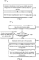
- FIG. 5 illustrates a schematic diagram 500 of fractional subframe transmission according to embodiments of the invention.
- FIG. 5 exemplarily shows four subframes, subframes 0 to 3.
- there are three potential positions 521, 522 and 523 wherein the first potential position 521 corresponds to the start of subframe 0, for example, symbol 0 of subframe 0.
- CCA/eCCA 501 may start from the first potential position 521.
- the transmitter may determine that the channel is available at a position 524. Since the position 524 is not a potential position, the transmitter may transmit channel occupation signals from the position 524 until a potential position, for example, the potential position 522, and determine the potential position 522 as the target position.
- the factional subframe transmission then may start from the target position, wherein control information may be transmitted on PDCCH at time periods 503, 505, 507 and 509, and data may be transmitted on PDSCH at time periods 504, 506, 508 and 510.
- FIG. 2 illustrates a flow chart of a method 200 for performing fractional subframe transmission at a transmitter according to another embodiment of the invention.
- the method 200 may be considered as a specific implementation of the method 100 described above with reference to Fig. 1 . However, it is noted that this is only for the purpose of illustrating the principles of the present invention, rather than limiting the scope thereof.
- Method 200 begins at step S210, in which a channel is detected as becoming available.
- whether a channel is available may be detected in several ways, such as energy detection, carrier sensing, and so on.
- strength of energy from a further transmitter may be measured on the channel.
- the further transmitter may be a transmitter that may use the same channel and is different from the transmitter performing the method according to embodiments of the present invention. If the energy strength is not strong, it may be determined that the channel is idle. In this regard, the energy strength may be compared with a strength threshold. In response to that the measured strength is less than the strength threshold, the channel may be determined as being available.
- the strength threshold may be a predetermined threshold, which may be set according to system requirements, specifications, channel quality, and so on.
- the strength threshold may be set as a fixed value or a value that is changed dynamically. It is to be understood that the above example embodiments are only for the purpose of illustration, without suggesting any limitations on the subject matter described herein.
- the strength threshold may be implemented in any other suitable ways.
- the channel availability may be detected based on carrier sensing.
- a signalling from a further transmitter may be detected on the channel.
- the further transmitter may be a transmitter that may use the channel and is different from the transmitter performing the method according to embodiments of the present invention. Based on the signalling, whether the channel is available may be determined.
- step S220 whether a current position is a potential position is detected.
- step S240 the potential position is determined as the target position. If the current position is not a potential position, the flow goes to step S230, where a channel occupation signal is transmitted from the current position until a potential position. Then, the flow goes to step S240, where the potential position is determined as the target position.
- a number of available symbols in the subframe are determined based on the target position.
- the number of available symbols may be determined based on the target position and the total number of symbols in a subframe. For way of example, if there are 14 symbols in one subframe, and if the target position corresponds to the sixth symbol, that is, symbol 5, it may be determined that there are 8 available symbols, i.e., symbols 6 to 13. For another example, if there are 12 symbols in one subframe, and if the target position corresponds to the eighth symbol, that is, symbol 7, it may be determined that there are 4 available symbols, i.e., symbols 8 to 11.
- control information and/or data of the fractional subframe transmission are transmitted from the target position based on the number of the available symbols.
- normal control information for example normal PDCCH
- shortened control information for example shortened PDCCH
- the normal PDCCH may occupy 3 symbols and the shortened PDCCH may occupy 1 or 2 symbols.
- the transmitter may transmit the control information and the data in the available symbols of the subframe and a subframe immediately following the subframe.
- the transmitter may transmit the control information in the available symbols of the subframe and transmit the data in a subframe immediately following the subframe.
- the transmitter may transmit a first part of the control information in the available symbols of the subframe and a second part of the control information in a further subframe immediately following the subframe, wherein the first part and the second part constitute the control information.
- the transmitter may transmit the data in the further subframe.
- the predetermined threshold may be set as a fixed value or a value that is changed dynamically, and may be configured by high layer signalling or prescribed by specifications. In an exemplary embodiment, the predetermined threshold may be set as 3.
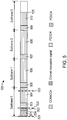
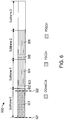
- FIG. 6 illustrates a schematic diagram 600 of fractional subframe transmission according to embodiments of the invention.
- FIG. 6 exemplarily shows four subframes, subframes 0 to 3.
- CCA/eCCA 601 may start from the first potential position 621.
- the transmitter may determine that the channel is available at the potential position 622.
- the potential position 622 may be determined as the target position.
- the factional subframe transmission then may start from the target position, wherein control information may be transmitted on PDCCH at time periods 602, 603 and 605, and data may be transmitted on PDSCH at time periods 604 and 606. As shown in FIG.
- the control information is transmitted in the available symbols of the subframe 0 and its following subframe 1, corresponding to the time periods 602 and 603 respectively.
- the data is transmitted at the time period 604.
- the first part of the control information is transmitted at the time period 602, and the second part of the control information is transmitted at the time period 603.
- the factional subframe transmission may ends at a portion of a subframe or at a full subframe.
- the factional subframe transmission ends at a position 525.
- a portion of subframe 3 is used for the factional subframe transmission.
- both the first subframe (i.e., subframe 0) and the last subframe (i.e., subframe 3) are fractional subframes.
- the factional subframe transmission terminates at the end of subframe 2. In other words, the factional subframe transmission ends at a full subframe.
- a transport block size in the fractional subframe may be determined based on the number of the available symbols and the data of the transport block size may be transmitted in the subframe.
- the transport block size indicates the size of a data block to be transmitted in the fractional subframe transmission.
- the transport block size may be determined in various ways.
- the transmitter may determine a scaling factor associated with the number of the available symbols, and then determine the transport block size based on the scaling factor.
- the scaling factor may be defined in several ways. Table 1 illustrates an example of scaling factors associated with different numbers of available symbols. Table 1 Number of available symbols Scaling factor 1, 2, 3 N/A 4 0.25 5 0.25, 0.375 6 0.375 7 0.375, 0.5 8 0.5, 0.75 9, 10, 11, 12 0.75 13, 14 1
- the transmitter may use the available symbols to transmit control information of the fractional subframe transmission, and may determine that the available symbols are not enough for transmitting data after the transmission of the control information.
- the scaling factor may be designed as a value of "N/A", which indicates that the scaling factor is "not available”.
- the transmitter may determine that the associated scaling factor is 0.25.
- the transmitter may determine that the associated scaling factor is 0.25 or 0.375.
- the transmitter may determine that the associated scaling factor is 0.375.
- the transmitter may determine that the associated scaling factor is 0.375 or 0.5. In an exemplary embodiment, if the number of the available symbols is 8, the transmitter may determine that the associated scaling factor is 0.5 or 0.75. In an exemplary embodiment, if the number of the available symbols is 9, 10, 11 or 12, the transmitter may determine that the associated scaling factor is 0.75. In an exemplary embodiment, if the number of the available symbols is 13 or 14, the transmitter may determine that the associated scaling factor is 1.
- the transport block size may be determined based on the scaling factor in several ways.
- a first resource block number which indicates a number of resource blocks allocated for transmission may be obtained.
- the first resource block number may be determined by the transmitter in real time.
- a second resource block number may be determined based on the first resource block number and the scaling factor.
- the transport block size may be determined.
- a transport block size table may be used for determining the transport block size.
- Table 2 illustrates an exemplary transport block size table.
- the horizontal direction of Table 2 may correspond to a resource block number, for example, the second resource block number in the embodiments, and the vertical direction may correspond to a Modulation and Coding Scheme (MCS).
- MCS Modulation and Coding Scheme
- the transmitter when the transmitter determines the second resource block number as well as the MCS that is employed currently, it may determine the transport block size by looking up the Table 2 based on the second resource block number and the MCS. By way of example, if the second resource block number is 8, and the MCS is 8 the transport block size may be determined as 1096.
- FIG. 3 illustrates a flow chart of a method 300 for performing fractional subframe transmission at a receiver according to an embodiment of the invention.
- the method 300 may be performed at a receiver, such as a UE, a D2D receiver, and other suitable device.
- a target position is determined from at least one potential position predefined in a subframe, the fractional subframe transmission starting at the target position.
- a plurality of potential positions may periodically correspond to symbols of the subframe, for example according to equation (1).
- the potential positions may correspond to the symbols 3, 8 and 12.
- the target position indicates when the fractional subframe transmission starts.
- the transmitter may send an indicator at the target position to a receiver, wherein the indicator, for example PCFICH, may indicate a size of control information of the fractional subframe transmission.
- the target position may be indicated explicitly.
- the receiver it may detect the indicator at one of the at least one potential position, for example, denoted as potential position 1.
- the receiver may determine the one of the at least one potential position as the target position. Otherwise, the receiver may determine that this potential position is not the target position and carry out the same detection on a further potential position, for example potential position 2, and so on.
- the transmitter may not send the indicator.
- the receiver may make blind decoding for control information of the fractional subframe transmission at one of the at least one potential position.
- the receiver may determine the one of the at least one potential position as the target position.
- step S320 the fractional subframe transmission is received from the target position.
- the receiver may know the size of the control information and accordingly receive the control information from the target position.
- a number of available symbols in the subframe may be determined based on the target position, and the control information and data of the fractional subframe transmission may be received based on the number of the available symbols.
- the control information may be transmitted before the data.
- the receiver may receive control information prior to the data.
- it is possible that the data is transmitted before the control information. As such, the receiver may receive the data prior to the control information. Details will be discussion with reference to embodiments of FIG. 4 .
- FIG. 4 illustrates a flow chart of a method 400 for performing fractional subframe transmission at a receiver according to another embodiment of the invention.
- the method 400 may be considered as a specific implementation of the method 300 described above with reference to Fig. 3 . However, it is noted that this is only for the purpose of illustrating the principles of the present invention, rather than limiting the scope thereof.
- an indicator is detected at one of the at least one potential position, the indicator indicating a size of control information of the fractional subframe transmission.
- the transmitter may send an indicator, for example PCFICH, at the target position to a receiver, to indicate a size of control information of the fractional subframe transmission.
- the receiver may detect the indicator at one of the at least one potential position.
- the one of the at least one potential position is determined as the target position. Otherwise, the receiver may detect the indicator at a further potential position.
- a number of available symbols in the subframe is determined based on the target position.
- the number of available symbols may be determined based on the target position and the total number of symbols in a subframe. By way of example, if there are 14 symbols in one subframe, and if the target position corresponds to the sixth symbol, that is, symbol 5, it may be determined that there are 8 available symbols, i.e., symbols 6 to 13. For another example, if there are 12 symbols in one subframe, and if the target position corresponds to the eighth symbol, that is, symbol 7, it may be determined that there are 4 available symbols, i.e., symbols 8 to 11.
- control information and data of the fractional subframe transmission are received based on the number of the available symbols.
- the receiver may receive the control information and the data in the available symbols and a subframe immediately following the subframe. In an exemplary embodiment, if the number of the available symbols is equal to the size of the control information, the receiver may receive the control information in the available symbols of the subframe and receive the data in a subframe immediately following the subframe. In a further exemplary embodiment, if the number of the available symbols is less than the size of the control information, the receiver may receive a first part of the control information in the available symbols of the subframe and a second part of the control information in a further subframe immediately following the subframe, wherein the first part and the second part constitute the control information. After the control information is received, the receiver may receive the data in the further subframe.
- a transport block size in the subframe may be determined based on the number of the available symbols. Then, the data of the transport block size may be received in the subframe.
- the transport block size indicates the size of a data block to be transmitted in the fractional subframe transmission.
- the transport block size may be determined in various ways.
- the receiver may determine a scaling factor associated with the number of the available symbols, and then determine the transport block size based on the scaling factor.
- the scaling factor may be defined in several ways. As discussed above, Table 1 illustrates an example of scaling factors associated with different numbers of available symbols.
- the receiver may determine that there is no data transmitted and there is no need to determine the transport block size. In an exemplary embodiment, if the number of the available symbols is 4, the receiver may determine that the associated scaling factor is 0.25. In an exemplary embodiment, if the number of the available symbols is 5, the receiver may determine that the associated scaling factor is 0.25 or 0.375. In an exemplary embodiment, if the number of the available symbols is 6, the receiver may determine that the associated scaling factor is 0.375. In an exemplary embodiment, if the number of the available symbols is 7, the receiver may determine that the associated scaling factor is 0.375 or 0.5.
- the receiver may determine that the associated scaling factor is 0.5 or 0.75. In an exemplary embodiment, if the number of the available symbols is 9, 10, 11 or 12, the receiver may determine that the associated scaling factor is 0.75. In an exemplary embodiment, if the number of the available symbols is 13 or 14, the receiver may determine that the associated scaling factor is 1.
- the transport block size may be determined based on the scaling factor in several ways.
- a first resource block number which indicates a number of resource blocks allocated for transmission may be obtained.
- the first resource block number may be notified by the transmitter.
- a second resource block number may be determined based on the first resource block number and the scaling factor.
- the second resource block number may be determined according to equation (2).
- the transport block size may be determined.
- a transport block size table for example Table 2, may be used for determining the transport block size.
- the receiver determines the second resource block number as well as the MCS which is employed currently, it may determine the transport block size by looking up the Table 2.
- FIG. 7 illustrates a block diagram of an apparatus 700 for performing fractional subframe transmission according to embodiments of the invention.
- the apparatus 700 may be implemented at a transmitter, for example, a BS, a D2D transmitter or any other applicable device.
- the apparatus 700 comprises: a first determining unit 710 configured to in response to detecting that a channel becomes available, determine a target position from at least one potential position predefined in a subframe; and a performing unit 720 configured to perform the fractional subframe transmission from the target position.
- the first determining unit 710 may comprise: a potential position detecting unit configured to detect whether a current position is a potential position; and a first target position determining unit configured to responsive to that the current position is a potential position, determine the potential position as the target position, and responsive to that the current position is not a potential position, transmit a channel occupation signal from the current position until a potential position and determine the potential position as the target position.
- each of the at least one potential position may correspond to a symbol of the subframe periodically or aperiodically.
- the performing unit 720 may comprise: a sending unit configured to send an indicator at the target position, the indicator indicating a size of control information of the fractional subframe transmission.
- the performing unit 720 may comprise: a first available symbol number determining unit configured to determine a number of available symbols in the subframe based on the target position; and a transmitting unit configured to transmit control information and data of the fractional subframe transmission from the target position based on the number of the available symbols.
- the transmitting unit may be further configured to: responsive to the number of the available symbols is less than or equal to a predetermined threshold, transmit the control information and the data in the available symbols and a subframe immediately following the subframe.
- the transmitting unit may comprise: a size determining unit configured to determine a transport block size in the subframe based on the number of the available symbols, wherein the transmitting unit may be further configured to transmit the data of the transport block size in the subframe.
- the performing unit 720 may comprise: a scheduling information obtaining unit configured to obtain preconfigured scheduling information associated with the target position, wherein the performing unit may be further configured to perform the fractional subframe transmission based on the preconfigured scheduling information.
- FIG. 8 illustrates a block diagram of an apparatus 800 for performing fractional subframe transmission according to embodiments of the invention.
- the apparatus 800 may be implemented at a receiver, for example, a cellular UE, a D2D receiver or any other applicable device.
- the apparatus 800 comprises: a second determining unit 810 configured to determine a target position from at least one potential position predefined in a subframe, the fractional subframe transmission starting at the target position; and a receiving unit 820 configured to receive the fractional subframe transmission from the target position.
- the second determining unit 810 may comprise: an indicator detecting unit configured to detect an indicator at one of the at least one potential position, the indicator indicating a size of control information of the fractional subframe transmission; and a second target position determining unit configured to in response to that the indicator is detected, determine the one of the at least one potential position as the target position.
- the second determining unit 810 may comprise: a decoding unit configured to make blind decoding for control information of the fractional subframe transmission at one of the at least one potential position; and a third target position determining unit configured to in response to that the blind decoding is success, determine the one of the at least one potential position as the target position.
- each of the at least one potential position may correspond to a symbol of the subframe periodically or aperiodically.
- the receiving unit 820 may comprise: a second available symbol number determining unit configured to determine a number of available symbols in the subframe based on the target position, wherein the receiving unit may be further configured to receive control information and data of the fractional subframe transmission based on the number of the available symbols.
- the receiving unit 820 may be further configured to responsive to the number of the available symbols is less than or equal to a predetermined threshold, receive the control information and the data in the available symbols and a subframe immediately following the subframe.
- the receiving unit 820 may comprise: a size determining unit configured to determine a transport block size in the subframe based on the number of the available symbols, wherein the receiving unit may be further configured to receive the data of the transport block size in the subframe.
- apparatuses 700 and 800 may be respectively implemented by any suitable technique either known at present or developed in the future. Further, a single device shown in FIG. 7 or FIG. 8 may be alternatively implemented in multiple devices separately, and multiple separated devices may be implemented in a single device. The scope of the present invention is not limited in these regards.
- the apparatus 700 may be configured to implement functionalities as described with reference to FIGs.1-2
- the apparatus 800 may be configured to implement functionalities as described with reference to FIGs. 3-4 . Therefore, the features discussed with respect to the method 100 or 200 may apply to the corresponding components of the apparatus 700, and the features discussed with respect to the method 300 or 400 may apply to the corresponding components of the apparatus 800.
- the components of the apparatus 700 or the apparatus 800 may be embodied in hardware, software, firmware, and/or any combination thereof.
- the components of the apparatus 700 or the apparatus 800 may be respectively implemented by a circuit, a processor or any other appropriate device. Those skilled in the art will appreciate that the aforesaid examples are only for illustration not limitation.
- the apparatus 700 or the apparatus 800 may comprise at least one processor.
- the at least one processor suitable for use with embodiments of the present disclosure may include, by way of example, both general and special purpose processors already known or developed in the future.
- the apparatus 700 or the apparatus 800 may further comprise at least one memory.
- the at least one memory may include, for example, semiconductor memory devices, e.g., RAM, ROM, EPROM, EEPROM, and flash memory devices.
- the at least one memory may be used to store program of computer executable instructions.
- the program can be written in any high-level and/or low-level compliable or interpretable programming languages.
- the computer executable instructions may be configured, with the at least one processor, to cause the apparatus 700 to at least perform according to the method 100 or 200 as discussed above, or to cause the apparatus 800 to at least perform according to the method 300 or 400 as discussed above.
- the present disclosure may be embodied in an apparatus, a method, or a computer program product.
- the various exemplary embodiments may be implemented in hardware or special purpose circuits, software, logic or any combination thereof.
- some aspects may be implemented in hardware, while other aspects may be implemented in firmware or software which may be executed by a controller, microprocessor or other computing device, although the disclosure is not limited thereto.
- FIGs. 1-4 may be viewed as method steps, and/or as operations that result from operation of computer program code, and/or as a plurality of coupled logic circuit elements constructed to carry out the associated function(s).
- At least some aspects of the exemplary embodiments of the disclosures may be practiced in various components such as integrated circuit chips and modules, and that the exemplary embodiments of this disclosure may be realized in an apparatus that is embodied as an integrated circuit, FPGA or ASIC that is configurable to operate in accordance with the exemplary embodiments of the present disclosure.
Description
- Embodiments of the present invention generally relate to communication techniques. More particularly, embodiments of the present invention relate to a method and apparatus for performing fractional subframe transmission.
- In 3rd Generation Partnership Project (3GPP), the network structure and various technologies needed for a terminal's movement between a 3GPP wireless communication network and a Wireless Local Area Network (WLAN) network are called interworking WLAN. The multi-mode wireless communication technology has evolved to use multiple wireless communication technologies at the same time. The use of multiple wireless communication technologies simultaneously thereby increases transfer rates per unit time or improves the reliability of the terminal.
- In wireless communication, the spectrum is very rare resource. A licensed band represents a frequency band that is exclusively licensed to a specific operator to provide specific wireless services. On the other hand, an unlicensed band represents a frequency band that is not allocated to a specific operator, but is opened so that all entities meeting the predefined requirements may use the frequency band.
- In some regions in the world, unlicensed band technologies need to abide to certain regulations, for example, Listen-Before-Talk (LBT), and channel bandwidth occupancy requirements. LBT results in an uncertainty of channel availability. For instance, an unlicensed band may be available at any time during a subframe.
- WLAN that uses Wireless Fidelity (WiFi) is the typical wireless communication technology used in the unlicensed band. Time granularity of current Long Term Evolution (LTE) is much larger than that of WiFi, which leads to the low competitive strength of License Assisted Access (LAA) with LBT. As such, fair coexistence between LTE and other technologies such as WiFi as well as between LTE operators is expected.
- In order to be more competitive in the unlicensed band, there is a need to perform fractional subframe transmission with low signaling overhead and high resource utilization.
-
US 2011/103315 discloses a coordinated signaling scheme for both uplink and downlink transmissions between a base station and a user terminal modifies the amount of time that the user terminal must turn on its receiver to listen for scheduling messages and ACK/NACK signaling. A scheduler at a base station aligns the transmission of downlink scheduling messages (e.g., downlink assignments) with uplink grants and ACK/NACK signaling for uplink transmissions. Aligning the downlink scheduling messages with uplink control signaling enables the user terminal to turn off its receiver for longer periods of time. - The present invention proposes a solution regarding fractional subframe transmission, as set out in the appended claims. Specifically, the present invention provides a method and apparatus for fractional subframe transmission with low signaling overhead and high resource utilization.
- According to a first example a method for performing fractional subframe transmission is provided. The method may comprise: in response to detecting that a channel becomes available, determining a target position from at least one potential position predefined in a subframe; and performing the fractional subframe transmission from the target position. The method may be performed at a transmitter.
- According to a second example a method for performing fractional subframe transmission is provided. The method may comprise: determining a target position from at least one potential position predefined in a subframe, the fractional subframe transmission starting at the target position; and receiving the fractional subframe transmission from the target position. The method may be performed at a receiver.
- According to a third example an apparatus for performing fractional subframe transmission is provided. The apparatus may comprise: a first determining unit configured to in response to detecting that a channel becomes available, determine a target position from at least one potential position predefined in a subframe; and a performing unit configured to perform the fractional subframe transmission from the target position. The apparatus may be implemented at a transmitter.
- According to a fourth example an apparatus for performing fractional subframe transmission is provided. The apparatus may comprise: a second determining unit configured to determine a target position from at least one potential position predefined in a subframe, the fractional subframe transmission starting at the target position; and a receiving unit configured to receive the fractional subframe transmission from the target position. The apparatus may be implemented at a receiver.
- Other features and advantages of the embodiments of the present invention will also be apparent from the following description of specific embodiments when read in conjunction with the accompanying drawings, which illustrate, by way of example, the principles of embodiments of the invention.
- Embodiments of the invention are presented in the sense of examples and their advantages are explained in greater detail below, with reference to the accompanying drawings, where
-
FIG. 1 illustrates a flow chart of amethod 100 for performing fractional subframe transmission at a transmitter according to an embodiment of the invention; -
FIG. 2 illustrates a flow chart of amethod 200 for performing fractional subframe transmission at a transmitter according to another embodiment of the invention; -
FIG. 3 illustrates a flow chart of amethod 300 for performing fractional subframe transmission at a receiver according to an embodiment of the invention; -
FIG. 4 illustrates a flow chart of amethod 400 for performing fractional subframe transmission at a receiver according to another embodiment of the invention; -
FIG. 5 illustrates a schematic diagram 500 of fractional subframe transmission according to embodiments of the invention; -
FIG. 6 illustrates a schematic diagram 600 of fractional subframe transmission according to embodiments of the invention; -
FIG. 7 illustrates a block diagram of anapparatus 700 for performing fractional subframe transmission according to embodiments of the invention; and -
FIG. 8 illustrates a block diagram of anapparatus 800 for performing fractional subframe transmission according to embodiments of the invention. - Throughout the figures, same or similar reference numbers indicate same or similar elements.
- The subject matter described herein will now be discussed with reference to several example embodiments. It should be understood these embodiments are discussed only for the purpose of enabling those skilled persons in the art to better understand and thus implement the subject matter described herein, rather than suggesting any limitations on the scope of the subject matter.
- The terminology used herein is for the purpose of describing particular embodiments only and is not intended to be limiting of example embodiments. As used herein, the singular forms "a," "an" and "the" are intended to include the plural forms as well, unless the context clearly indicates otherwise. It will be further understood that the terms "comprises," "comprising," "includes" and/or "including," when used herein, specify the presence of stated features, integers, steps, operations, elements and/or components, but do not preclude the presence or addition of one or more other features, integers, steps, operations, elements, components and/or groups thereof.
- It should also be noted that in some alternative implementations, the functions/acts noted may occur out of the order noted in the figures. For example, two functions or acts shown in succession may in fact be executed concurrently or may sometimes be executed in the reverse order, depending upon the functionality/acts involved.
- Embodiments of the present invention are directed to a solution for performing fractional subframe transmission. The solution may be carried out between a receiver and a transmitter. In particular, upon detecting that a channel becomes available, the transmitter may determine a target position from at least one potential position predefined in a subframe and perform the fractional subframe transmission from the target position. The receiver may determine a target position from the at least one predefined potential position in a similar way and receive the fractional subframe transmission from the target position. In this way, transmission may be performed without introducing signalling overhead. Meanwhile, once a channel enters an idle state, the transmission may start from the current subframe, instead of the next subframe. As such, resource utilization is improved.
- In embodiments of the present invention, a fractional subframe may refer to a subframe for downlink transmission or a subframe for uplink transmission, wherein one part of the fractional subframe is used for transmission of control information or data and the other part is not used for the transmission. For example, for a downlink subframe comprising 14 symbols, if only the last 6 symbols are available for in the downlink transmission while the first 8 symbols are unavailable, this subframe may be considered as a factional subframe.
- In the disclosure, the fractional subframe transmission may refer to the transmission performed on one or more subframes, and at least one of the one or more subframes is a fractional subframe. By way of example, the fractional subframe transmission may comprise various cases, such as the first subframe being a fractional subframe, the last subframe being a fractional subframe, both the first and the last subframes being fractional subframes, and the like.
- In some embodiments, the fractional subframe transmission may be downlink or uplink cellular transmission. In downlink transmission, the receiver may comprise user equipment (UE), such as a terminal, a Mobile Terminal (MT), a Subscriber Station (SS), a Portable Subscriber Station (PSS), Mobile Station (MS), or an Access Terminal (AT). Meanwhile, the transmitter may comprise a base station (BS), such as a node B (NodeB or NB), or an evolved NodeB (eNodeB or eNB). In uplink transmission, the transmitter may comprise a UE and the receiver may comprise a BS.
- According to some other embodiments of the present invention, the fractional subframe transmission may be D2D transmission. In this regard, the receiver may be a Device-to-Device (D2D) receiver and the transmitter may be a D2D transmitter.
- Embodiments of the present invention may be applied in various communication systems, including but not limited to a Long Term Evolution (LTE) system or a Long Term Evolution Advanced (LTE-A) system. Given the rapid development in communications, there will of course also be future type wireless communication technologies and systems with which the present invention may be embodied. It should not be seen as limiting the scope of the invention to only the aforementioned system.
- Now some exemplary embodiments of the present invention will be described below with reference to the figures. Reference is first made to
FIG. 1 , which illustrates a flow chart of amethod 100 for performing fractional subframe transmission at a transmitter according to an embodiment of the invention. Themethod 100 may be performed at a transmitter, such as a BS, a D2D transmitter, and other suitable device. - The
method 100 starts at step S110, in which in response to detecting that a channel becomes available, a target position is determined from at least one potential position predefined in a subframe. - According to embodiments of the present invention, a subframe may comprise a plurality of symbols. By way of example, a subframe may be 1ms and comprise 14 symbols, for example,
symbols 0 to 13. A position, such as a potential position, a target position, a current position, a next position, may refer to a time point or a time period in the subframe. In some embodiments, a position may correspond to an instant in a subframe. As an alternative, a position may correspond to a symbol of a subframe. In this regard, the position may occupy a time period, for example, the time period of a symbol. In the context, a target position may refer to a position from which the fractional transmission may start, and a potential position may refer to a predefined position that is a candidate of the target position. - According to embodiments of the present invention, there may be one or more potential positions predefined in a subframe. Each of the potential positions may correspond to a symbol of the subframe periodically or aperiodically. In some embodiments, the potential positions may comprise every three symbols, for example,
symbols 
- It is to be noted that the above examples are illustrated for example, rather than limitation. It can be appreciated that, in alternative embodiments, there may be aperiodic configurations of the potential positions. For instance, the potential positions may correspond to the
symbols - According to embodiments of the present invention, Clear Chanel Assessment (CCA) or Extended Clear Chanel Assessment (eCCA) may be performed. With the CCA/eCCA, the transmitter may detect whether a channel is available. In response to detecting that the channel becomes available, the transmitter may determine the target position from one or more potential positions in several ways. In some embodiments, whether a current position is a potential position is detected first. If the current position is a potential position, the potential position may be determined as the target position; otherwise, a channel occupation signal may be transmitted from the current position until a potential position and then the potential position may be determined as the target position.
- At step S120, the fractional subframe transmission is performed from the target position.
- According to embodiments of the present invention, at step S120, the transmitter may send an indicator at the target position to a receiver. The indicator may indicate a size of control information of the fractional subframe transmission, for example, the number of symbols of Physical Downlink Control Channel (PDCCH). In some embodiments, the indicator may be implemented as Physical Control Format Indicator Channel (PCFICH), or any other suitable indicator. Upon receiving the indicator, the receiver may know the size of the control information. For example, when the receiver detects PCFICH, it may have the knowledge of the number symbols of PDCCH. It is to be noted that the above example is shown only for illustration purpose, without suggesting any limitations on the scope of the subject matter described herein. As can be appreciated, in some embodiments, the control information may be configured by higher layer signaling or configured according to specification(s).
- According to embodiments of the present invention, at step S120, the transmitter may determine the number of available symbols in the subframe based on the target position, and transmit control information and data of the fractional subframe transmission from the target position based on the number of the available symbols. In some embodiments, the control information may be transmitted on PDCCH, and the data may be transmitted on Physical Downlink Shared Channel (PDSCH). Details of the embodiments will be described with reference to
FIG. 2 . - According to embodiments of the present invention, the scheduling information associated with each of the potential position may be preconfigured in advance. When performing the fractional subframe transmission, the transmitter may obtain the preconfigured scheduling information associated with the target position, and perform the fractional subframe transmission based on the preconfigured scheduling information. As such, upon determining the target position, the transmitter does not have to spend much time on configuring scheduling information associated with the target position. In this way, the fractional subframe transmission may be performed more quickly and efficiently.
-
FIG. 5 illustrates a schematic diagram 500 of fractional subframe transmission according to embodiments of the invention.FIG. 5 exemplarily shows four subframes,subframes 0 to 3. With respect tosubframe 0, there are threepotential positions potential position 521 corresponds to the start ofsubframe 0, for example,symbol 0 ofsubframe 0. CCA/eCCA 501 may start from the firstpotential position 521. During the CCA/eCCA 501, the transmitter may determine that the channel is available at aposition 524. Since theposition 524 is not a potential position, the transmitter may transmit channel occupation signals from theposition 524 until a potential position, for example, thepotential position 522, and determine thepotential position 522 as the target position. The factional subframe transmission then may start from the target position, wherein control information may be transmitted on PDCCH attime periods time periods - Reference is now made to
FIG. 2 , which illustrates a flow chart of amethod 200 for performing fractional subframe transmission at a transmitter according to another embodiment of the invention. Themethod 200 may be considered as a specific implementation of themethod 100 described above with reference toFig. 1 . However, it is noted that this is only for the purpose of illustrating the principles of the present invention, rather than limiting the scope thereof. -
Method 200 begins at step S210, in which a channel is detected as becoming available. - According to embodiments of the present invention, whether a channel is available may be detected in several ways, such as energy detection, carrier sensing, and so on. In some embodiments, strength of energy from a further transmitter may be measured on the channel. The further transmitter may be a transmitter that may use the same channel and is different from the transmitter performing the method according to embodiments of the present invention. If the energy strength is not strong, it may be determined that the channel is idle. In this regard, the energy strength may be compared with a strength threshold. In response to that the measured strength is less than the strength threshold, the channel may be determined as being available. The strength threshold may be a predetermined threshold, which may be set according to system requirements, specifications, channel quality, and so on. According to embodiments of the present invention, the strength threshold may be set as a fixed value or a value that is changed dynamically. It is to be understood that the above example embodiments are only for the purpose of illustration, without suggesting any limitations on the subject matter described herein. The strength threshold may be implemented in any other suitable ways.
- Alternatively, the channel availability may be detected based on carrier sensing. By way of example, a signalling from a further transmitter may be detected on the channel. The further transmitter may be a transmitter that may use the channel and is different from the transmitter performing the method according to embodiments of the present invention. Based on the signalling, whether the channel is available may be determined.
- It is to be noted although the above embodiments illustrate a further transmitter, there may be a plurality of further transmitters in a communication system according to embodiments of the present invention. In such embodiments, energy detection and carrier sensing may be performed with respect to the plurality of further transmitters.
- At step S220, whether a current position is a potential position is detected.
- If the current position is a potential position, the flow goes to step S240, where the potential position is determined as the target position. If the current position is not a potential position, the flow goes to step S230, where a channel occupation signal is transmitted from the current position until a potential position. Then, the flow goes to step S240, where the potential position is determined as the target position.
- At step S250, a number of available symbols in the subframe are determined based on the target position.
- In some embodiments, the number of available symbols may be determined based on the target position and the total number of symbols in a subframe. By way of example, if there are 14 symbols in one subframe, and if the target position corresponds to the sixth symbol, that is, symbol 5, it may be determined that there are 8 available symbols, i.e., symbols 6 to 13. For another example, if there are 12 symbols in one subframe, and if the target position corresponds to the eighth symbol, that is, symbol 7, it may be determined that there are 4 available symbols, i.e., symbols 8 to 11.
- At step S260, control information and/or data of the fractional subframe transmission are transmitted from the target position based on the number of the available symbols.
- In some embodiments, if the channel is available in earlier symbols of a subframe, for example,
symbol 0 to 6, normal control information, for example normal PDCCH, may be applied. If the channel is available in latter symbols of a subframe, for example, symbol 9 to 13, shortened control information, for example shortened PDCCH, may be applied. In an exemplary embodiment, the normal PDCCH may occupy 3 symbols and the shortened PDCCH may occupy 1 or 2 symbols. - Additionally, in some embodiments, responsive to the number of the available symbols is less than or equal to a predetermined threshold, the transmitter may transmit the control information and the data in the available symbols of the subframe and a subframe immediately following the subframe. In an exemplary embodiment, if the number of the available symbols is equal to the size of the control information, the transmitter may transmit the control information in the available symbols of the subframe and transmit the data in a subframe immediately following the subframe. In a further exemplary embodiment, if the number of the available symbols is less than the size of the control information, the transmitter may transmit a first part of the control information in the available symbols of the subframe and a second part of the control information in a further subframe immediately following the subframe, wherein the first part and the second part constitute the control information. After the control information is transmitted, the transmitter may transmit the data in the further subframe. According to embodiments of the present invention, the predetermined threshold may be set as a fixed value or a value that is changed dynamically, and may be configured by high layer signalling or prescribed by specifications. In an exemplary embodiment, the predetermined threshold may be set as 3.
-
FIG. 6 illustrates a schematic diagram 600 of fractional subframe transmission according to embodiments of the invention.FIG. 6 exemplarily shows four subframes,subframes 0 to 3. With respect tosubframe 0, there are twopotential positions eCCA 601 may start from the firstpotential position 621. During CCA/eCCA 601, the transmitter may determine that the channel is available at thepotential position 622. Thus, thepotential position 622 may be determined as the target position. The factional subframe transmission then may start from the target position, wherein control information may be transmitted on PDCCH attime periods time periods FIG. 6 , the control information is transmitted in the available symbols of thesubframe 0 and its followingsubframe 1, corresponding to thetime periods time period 604. In particular, the first part of the control information is transmitted at thetime period 602, and the second part of the control information is transmitted at thetime period 603. - It is to be noted that, the factional subframe transmission may ends at a portion of a subframe or at a full subframe. According to embodiments shown in
FIG. 5 , the factional subframe transmission ends at aposition 525. Thus, a portion ofsubframe 3 is used for the factional subframe transmission. In this case, both the first subframe (i.e., subframe 0) and the last subframe (i.e., subframe 3) are fractional subframes. Alternatively, as shown inFIG. 6 , the factional subframe transmission terminates at the end ofsubframe 2. In other words, the factional subframe transmission ends at a full subframe. - Additionally, in some embodiments, a transport block size in the fractional subframe may be determined based on the number of the available symbols and the data of the transport block size may be transmitted in the subframe.
- The transport block size indicates the size of a data block to be transmitted in the fractional subframe transmission. According to embodiments of the present invention, the transport block size may be determined in various ways. In some embodiments, the transmitter may determine a scaling factor associated with the number of the available symbols, and then determine the transport block size based on the scaling factor. The scaling factor may be defined in several ways. Table 1 illustrates an example of scaling factors associated with different numbers of available symbols.
Table 1 Number of available symbols Scaling factor 1, 2, 3 N/A 4 0.25 5 0.25, 0.375 6 0.375 7 0.375, 0.5 8 0.5, 0.75 9, 10, 11, 12 0.75 13, 14 1 - In some embodiments, if the number of the available symbols is 1, 2 or 3, the transmitter may use the available symbols to transmit control information of the fractional subframe transmission, and may determine that the available symbols are not enough for transmitting data after the transmission of the control information. In this regard, the scaling factor may be designed as a value of "N/A", which indicates that the scaling factor is "not available". In an exemplary embodiment, if the number of the available symbols is 4, the transmitter may determine that the associated scaling factor is 0.25. In an exemplary embodiment, if the number of the available symbols is 5, the transmitter may determine that the associated scaling factor is 0.25 or 0.375. In an exemplary embodiment, if the number of the available symbols is 6, the transmitter may determine that the associated scaling factor is 0.375. In an exemplary embodiment, if the number of the available symbols is 7, the transmitter may determine that the associated scaling factor is 0.375 or 0.5. In an exemplary embodiment, if the number of the available symbols is 8, the transmitter may determine that the associated scaling factor is 0.5 or 0.75. In an exemplary embodiment, if the number of the available symbols is 9, 10, 11 or 12, the transmitter may determine that the associated scaling factor is 0.75. In an exemplary embodiment, if the number of the available symbols is 13 or 14, the transmitter may determine that the associated scaling factor is 1.
- In some embodiments, the transport block size may be determined based on the scaling factor in several ways. By way of example, a first resource block number which indicates a number of resource blocks allocated for transmission may be obtained. For the transmitter, the first resource block number may be determined by the transmitter in real time. Then, a second resource block number may be determined based on the first resource block number and the scaling factor. In an exemplary embodiment, the second resource block number may be determined as follows:

- Based on the second resource block number, the transport block size may be determined. In some embodiments, a transport block size table may be used for determining the transport block size. Table 2 illustrates an exemplary transport block size table.

- The horizontal direction of Table 2 may correspond to a resource block number, for example, the second resource block number in the embodiments, and the vertical direction may correspond to a Modulation and Coding Scheme (MCS). In the embodiments, when the transmitter determines the second resource block number as well as the MCS that is employed currently, it may determine the transport block size by looking up the Table 2 based on the second resource block number and the MCS. By way of example, if the second resource block number is 8, and the MCS is 8 the transport block size may be determined as 1096.
- It is to be noted that although the dimension of Table 2 is 10 × 27, it is simplification of 3GPP TS36.213 whose dimension is 34 × 110. It is further to be noted that the above example table is only for the purpose of illustration, without suggesting any limitations on the subject matter described herein. Any other suitable table may be used in the determination of the transport block size.
- Reference is now made to
FIG. 3 , which illustrates a flow chart of amethod 300 for performing fractional subframe transmission at a receiver according to an embodiment of the invention. Themethod 300 may be performed at a receiver, such as a UE, a D2D receiver, and other suitable device. - At step S310, a target position is determined from at least one potential position predefined in a subframe, the fractional subframe transmission starting at the target position.
- According to embodiments of the present invention, there may be at least one potential position predefined in a subframe. In some embodiments, a plurality of potential positions may periodically correspond to symbols of the subframe, for example according to equation (1). Alternatively, there may be aperiodic configurations of the potential positions. For instance, the potential positions may correspond to the
symbols 3, 8 and 12. - The target position indicates when the fractional subframe transmission starts. There may be several ways for the receiver to determine the target position based on one or more potential positions predefined in the subframe. In some embodiments, the transmitter may send an indicator at the target position to a receiver, wherein the indicator, for example PCFICH, may indicate a size of control information of the fractional subframe transmission. In this way, the target position may be indicated explicitly. For the receiver, it may detect the indicator at one of the at least one potential position, for example, denoted as
potential position 1. In response to that the indicator is detected, the receiver may determine the one of the at least one potential position as the target position. Otherwise, the receiver may determine that this potential position is not the target position and carry out the same detection on a further potential position, for examplepotential position 2, and so on. - Alternatively, in some embodiments, the transmitter may not send the indicator. In this case, the receiver may make blind decoding for control information of the fractional subframe transmission at one of the at least one potential position. In response to that the blind decoding is success, the receiver may determine the one of the at least one potential position as the target position.
- At step S320, the fractional subframe transmission is received from the target position.
- In some embodiments, based on the indicator indicating the size of control information of the fractional subframe transmission, the receiver may know the size of the control information and accordingly receive the control information from the target position.
- According to embodiments of the present invention, a number of available symbols in the subframe may be determined based on the target position, and the control information and data of the fractional subframe transmission may be received based on the number of the available symbols. In some embodiments, during the fractional subframe transmission, the control information may be transmitted before the data. In this case, the receiver may receive control information prior to the data. In some alternative embodiments, it is possible that the data is transmitted before the control information. As such, the receiver may receive the data prior to the control information. Details will be discussion with reference to embodiments of
FIG. 4 . -
FIG. 4 illustrates a flow chart of amethod 400 for performing fractional subframe transmission at a receiver according to another embodiment of the invention. Themethod 400 may be considered as a specific implementation of themethod 300 described above with reference toFig. 3 . However, it is noted that this is only for the purpose of illustrating the principles of the present invention, rather than limiting the scope thereof. - At step S410, an indicator is detected at one of the at least one potential position, the indicator indicating a size of control information of the fractional subframe transmission.
- In some embodiments, the transmitter may send an indicator, for example PCFICH, at the target position to a receiver, to indicate a size of control information of the fractional subframe transmission. In this case, the receiver may detect the indicator at one of the at least one potential position. At step S420, in response to that the indicator is detected, the one of the at least one potential position is determined as the target position. Otherwise, the receiver may detect the indicator at a further potential position.
- At step S430, a number of available symbols in the subframe is determined based on the target position.
- This step is similar to step S250. In some embodiments, the number of available symbols may be determined based on the target position and the total number of symbols in a subframe. By way of example, if there are 14 symbols in one subframe, and if the target position corresponds to the sixth symbol, that is, symbol 5, it may be determined that there are 8 available symbols, i.e., symbols 6 to 13. For another example, if there are 12 symbols in one subframe, and if the target position corresponds to the eighth symbol, that is, symbol 7, it may be determined that there are 4 available symbols, i.e., symbols 8 to 11.
- At step S440, control information and data of the fractional subframe transmission are received based on the number of the available symbols.
- In some embodiments, responsive to the number of the available symbols is less than or equal to a predetermined threshold, the receiver may receive the control information and the data in the available symbols and a subframe immediately following the subframe. In an exemplary embodiment, if the number of the available symbols is equal to the size of the control information, the receiver may receive the control information in the available symbols of the subframe and receive the data in a subframe immediately following the subframe. In a further exemplary embodiment, if the number of the available symbols is less than the size of the control information, the receiver may receive a first part of the control information in the available symbols of the subframe and a second part of the control information in a further subframe immediately following the subframe, wherein the first part and the second part constitute the control information. After the control information is received, the receiver may receive the data in the further subframe.
- Additionally, in some embodiments, a transport block size in the subframe may be determined based on the number of the available symbols. Then, the data of the transport block size may be received in the subframe.
- The transport block size indicates the size of a data block to be transmitted in the fractional subframe transmission. According to embodiments of the present invention, the transport block size may be determined in various ways. In some embodiments, the receiver may determine a scaling factor associated with the number of the available symbols, and then determine the transport block size based on the scaling factor. The scaling factor may be defined in several ways. As discussed above, Table 1 illustrates an example of scaling factors associated with different numbers of available symbols.
- In an exemplary embodiment, if the number of the available symbols is 1, 2 or 3, the receiver may determine that there is no data transmitted and there is no need to determine the transport block size. In an exemplary embodiment, if the number of the available symbols is 4, the receiver may determine that the associated scaling factor is 0.25. In an exemplary embodiment, if the number of the available symbols is 5, the receiver may determine that the associated scaling factor is 0.25 or 0.375. In an exemplary embodiment, if the number of the available symbols is 6, the receiver may determine that the associated scaling factor is 0.375. In an exemplary embodiment, if the number of the available symbols is 7, the receiver may determine that the associated scaling factor is 0.375 or 0.5. In an exemplary embodiment, if the number of the available symbols is 8, the receiver may determine that the associated scaling factor is 0.5 or 0.75. In an exemplary embodiment, if the number of the available symbols is 9, 10, 11 or 12, the receiver may determine that the associated scaling factor is 0.75. In an exemplary embodiment, if the number of the available symbols is 13 or 14, the receiver may determine that the associated scaling factor is 1.
- In some embodiments, the transport block size may be determined based on the scaling factor in several ways. By way of example, a first resource block number which indicates a number of resource blocks allocated for transmission may be obtained. For the receiver, the first resource block number may be notified by the transmitter. Then, a second resource block number may be determined based on the first resource block number and the scaling factor. In an exemplary embodiment, the second resource block number may be determined according to equation (2). Based on the second resource block number, the transport block size may be determined. In some embodiments, a transport block size table, for example Table 2, may be used for determining the transport block size. In particular, if the receiver determines the second resource block number as well as the MCS which is employed currently, it may determine the transport block size by looking up the Table 2.
-
FIG. 7 illustrates a block diagram of anapparatus 700 for performing fractional subframe transmission according to embodiments of the invention. In accordance with embodiments of the present invention, theapparatus 700 may be implemented at a transmitter, for example, a BS, a D2D transmitter or any other applicable device. - As shown, the
apparatus 700 comprises: a first determiningunit 710 configured to in response to detecting that a channel becomes available, determine a target position from at least one potential position predefined in a subframe; and a performingunit 720 configured to perform the fractional subframe transmission from the target position. - According to embodiments of the present invention, the first determining
unit 710 may comprise: a potential position detecting unit configured to detect whether a current position is a potential position; and a first target position determining unit configured to responsive to that the current position is a potential position, determine the potential position as the target position, and responsive to that the current position is not a potential position, transmit a channel occupation signal from the current position until a potential position and determine the potential position as the target position. - According to embodiments of the present invention, each of the at least one potential position may correspond to a symbol of the subframe periodically or aperiodically.
- According to embodiments of the present invention, the performing
unit 720 may comprise: a sending unit configured to send an indicator at the target position, the indicator indicating a size of control information of the fractional subframe transmission. - According to embodiments of the present invention, the performing
unit 720 may comprise: a first available symbol number determining unit configured to determine a number of available symbols in the subframe based on the target position; and a transmitting unit configured to transmit control information and data of the fractional subframe transmission from the target position based on the number of the available symbols. - In some embodiments, the transmitting unit may be further configured to: responsive to the number of the available symbols is less than or equal to a predetermined threshold, transmit the control information and the data in the available symbols and a subframe immediately following the subframe.
- In some embodiments, the transmitting unit may comprise: a size determining unit configured to determine a transport block size in the subframe based on the number of the available symbols, wherein the transmitting unit may be further configured to transmit the data of the transport block size in the subframe.
- According to embodiments of the present invention, the performing
unit 720 may comprise: a scheduling information obtaining unit configured to obtain preconfigured scheduling information associated with the target position, wherein the performing unit may be further configured to perform the fractional subframe transmission based on the preconfigured scheduling information. -
FIG. 8 illustrates a block diagram of anapparatus 800 for performing fractional subframe transmission according to embodiments of the invention. In accordance with embodiments of the present invention, theapparatus 800 may be implemented at a receiver, for example, a cellular UE, a D2D receiver or any other applicable device. - As shown, the
apparatus 800 comprises: a second determiningunit 810 configured to determine a target position from at least one potential position predefined in a subframe, the fractional subframe transmission starting at the target position; and a receivingunit 820 configured to receive the fractional subframe transmission from the target position. - According to embodiments of the present invention, the second determining
unit 810 may comprise: an indicator detecting unit configured to detect an indicator at one of the at least one potential position, the indicator indicating a size of control information of the fractional subframe transmission; and a second target position determining unit configured to in response to that the indicator is detected, determine the one of the at least one potential position as the target position. - According to embodiments of the present invention, the second determining
unit 810 may comprise: a decoding unit configured to make blind decoding for control information of the fractional subframe transmission at one of the at least one potential position; and a third target position determining unit configured to in response to that the blind decoding is success, determine the one of the at least one potential position as the target position. - According to embodiments of the present invention, each of the at least one potential position may correspond to a symbol of the subframe periodically or aperiodically.
- According to embodiments of the present invention, the receiving
unit 820 may comprise: a second available symbol number determining unit configured to determine a number of available symbols in the subframe based on the target position, wherein the receiving unit may be further configured to receive control information and data of the fractional subframe transmission based on the number of the available symbols. - According to embodiments of the present invention, the receiving
unit 820 may be further configured to responsive to the number of the available symbols is less than or equal to a predetermined threshold, receive the control information and the data in the available symbols and a subframe immediately following the subframe. - According to embodiments of the present invention, the receiving
unit 820 may comprise: a size determining unit configured to determine a transport block size in the subframe based on the number of the available symbols, wherein the receiving unit may be further configured to receive the data of the transport block size in the subframe. - It is also to be noted that the
apparatuses FIG. 7 or FIG. 8 may be alternatively implemented in multiple devices separately, and multiple separated devices may be implemented in a single device. The scope of the present invention is not limited in these regards. - It is noted that the
apparatus 700 may be configured to implement functionalities as described with reference toFIGs.1-2 , and theapparatus 800 may be configured to implement functionalities as described with reference toFIGs. 3-4 . Therefore, the features discussed with respect to themethod apparatus 700, and the features discussed with respect to themethod apparatus 800. It is further noted that the components of theapparatus 700 or theapparatus 800 may be embodied in hardware, software, firmware, and/or any combination thereof. For example, the components of theapparatus 700 or theapparatus 800 may be respectively implemented by a circuit, a processor or any other appropriate device. Those skilled in the art will appreciate that the aforesaid examples are only for illustration not limitation. - In some embodiment of the present disclosure, the
apparatus 700 or theapparatus 800 may comprise at least one processor. The at least one processor suitable for use with embodiments of the present disclosure may include, by way of example, both general and special purpose processors already known or developed in the future. Theapparatus 700 or theapparatus 800 may further comprise at least one memory. The at least one memory may include, for example, semiconductor memory devices, e.g., RAM, ROM, EPROM, EEPROM, and flash memory devices. The at least one memory may be used to store program of computer executable instructions. The program can be written in any high-level and/or low-level compliable or interpretable programming languages. In accordance with embodiments, the computer executable instructions may be configured, with the at least one processor, to cause theapparatus 700 to at least perform according to themethod apparatus 800 to at least perform according to themethod - Based on the above description, the skilled in the art would appreciate that the present disclosure may be embodied in an apparatus, a method, or a computer program product. In general, the various exemplary embodiments may be implemented in hardware or special purpose circuits, software, logic or any combination thereof. For example, some aspects may be implemented in hardware, while other aspects may be implemented in firmware or software which may be executed by a controller, microprocessor or other computing device, although the disclosure is not limited thereto. While various aspects of the exemplary embodiments of this disclosure may be illustrated and described as block diagrams, flowcharts, or using some other pictorial representation, it is well understood that these blocks, apparatus, systems, techniques or methods described herein may be implemented in, as non-limiting examples, hardware, software, firmware, special purpose circuits or logic, general purpose hardware or controller or other computing devices, or some combination thereof.
- The various blocks shown in
FIGs. 1-4 may be viewed as method steps, and/or as operations that result from operation of computer program code, and/or as a plurality of coupled logic circuit elements constructed to carry out the associated function(s). At least some aspects of the exemplary embodiments of the disclosures may be practiced in various components such as integrated circuit chips and modules, and that the exemplary embodiments of this disclosure may be realized in an apparatus that is embodied as an integrated circuit, FPGA or ASIC that is configurable to operate in accordance with the exemplary embodiments of the present disclosure. - While this specification contains many specific implementation details, these should not be construed as limitations on the scope of any disclosure or of what may be claimed, but rather as descriptions of features that may be specific to particular embodiments of particular disclosures. Certain features that are described in this specification in the context of separate embodiments can also be implemented in combination in a single embodiment. Conversely, various features that are described in the context of a single embodiment can also be implemented in multiple embodiments separately or in any suitable sub-combination. Moreover, although features may be described above as acting in certain combinations and even initially claimed as such, one or more features from a claimed combination can in some cases be excised from the combination, and the claimed combination may be directed to a sub-combination or variation of a sub-combination.
- Similarly, while operations are depicted in the drawings in a particular order, this should not be understood as requiring that such operations be performed in the particular order shown or in sequential order, or that all illustrated operations be performed, to achieve desirable results. In certain circumstances, multitasking and parallel processing may be advantageous. Moreover, the separation of various system components in the embodiments described above should not be understood as requiring such separation in all embodiments, and it should be understood that the described program components and systems can generally be integrated together in a single software product or packaged into multiple software products.
- Various modifications, adaptations to the foregoing exemplary embodiments of this disclosure may become apparent to those skilled in the relevant arts in view of the foregoing description, when read in conjunction with the accompanying drawings. Any and all modifications will still fall within the scope of the non-limiting and exemplary embodiments of this disclosure. Furthermore, other embodiments of the disclosures set forth herein will come to mind to one skilled in the art to which these embodiments of the disclosure pertain having the benefit of the teachings presented in the foregoing descriptions and the associated drawings.
- Therefore, it is to be understood that the embodiments of the disclosure are not to be limited to the specific embodiments disclosed and that modifications and other embodiments are intended to be included within the scope of the appended claims. Although specific terms are used herein, they are used in a generic and descriptive sense only and not for purpose of limitation.
Claims (14)
- A method of performing fractional subframe transmission (500) in a wireless communication system, comprising:in response to detecting that a channel becomes available;performing the fractional subframe transmission (500) from a target position, wherein the target position is any one of at least one potential position predefined in a subframe,wherein each of the at least one potential position corresponds to a symbol of the subframe periodically.
- The method of Claim 1, wherein the transmission occupies one or more consecutive subframes, and a subframe of the one or more consecutive subframes comprises symbols used for transmission while other symbols in the subframe are not occupied.
- The method of Claim 1, wherein performing the fractional subframe transmission (500) from the target position comprises:
sending an indicator at the target position, the indicator indicating a size of control information of the fractional subframe transmission. - The method of Claim 1, wherein performing the fractional subframe transmission (500) from the target position comprises:determining a number of available symbols in the subframe based on the target position; andtransmitting control information and data of the fractional subframe transmission (500) from the target position based on the number of the available symbols.
- A method of performing fractional subframe transmission, comprising:receiving the fractional subframe transmission (500) from a target position, wherein the target position is any one of the at least one potential position predefined in a subframe,wherein each of the at least one potential position corresponds to a symbol of the subframe periodically.
- The method of Claim 5, wherein the method further comprises:making blind decoding for control information of the fractional subframe transmission (500) at one of the at least one potential position; andin response to that the blind decoding is success, determining the one of the at least one potential position as the target position.
- The method of Claim 5, wherein the transmission occupies one or more consecutive subframes, and a subframe of the one or more consecutive subframes comprises symbols used for transmission while other symbols in the sub frame are not occupied.
- An apparatus (700) of performing fractional subframe transmission (500) in a wireless communication system, comprising:a first determining unit (710) configured to detect that a channel becomes available; anda performing unit (720) configured to perform the fractional subframe transmission (500) from a target position, wherein the target position is any one of at least one potential position predefined in a subframe,wherein each of the at least one potential position corresponds to a symbol of the subframe periodically.
- The apparatus (700) of Claim 8, wherein the transmission occupies one or more consecutive subframes, and a subframe of the one or more consecutive subframes comprises symbols used for transmission while other symbols in the subframe are not occupied.
- The apparatus (700) of Claim 8, wherein the performing unit comprises:
a sending unit configured to send an indicator at the target position, the indicator indicating a size of control information of the fractional subframe transmission. - The apparatus (700) of Claim 8, wherein the performing unit comprises:a first available symbol number determining unit configured to determine a number of available symbols in the subframe based on the target position; anda transmitting unit configured to transmit control information and data of the fractional subframe transmission (500) from the target position based on the number of the available symbols.
- An apparatus (800) of performing fractional subframe transmission (500) in a wireless communication system, comprising:a receiving unit (820) configured to receive the fractional subframe transmission (500) from a target position, wherein the target position is any one of at least one potential position predefined in a subframe,wherein each of the at least one potential position corresponds to a symbol of the subframe periodically.
- The apparatus (800) of Claim 12, comprising a second determining unit having:a decoding unit configured to make blind decoding for control information of the fractional subframe transmission (500) at one of the at least one potential position; anda third target position determining unit configured to in response to that the blind decoding is success, determine the one of the at least one potential position as the target position.
- The apparatus of Claim 12, wherein the transmission occupies one or more consecutive subframes, and a subframe of the one or more consecutive subframes comprises symbols used for transmission while other symbols in the subframe are not occupied.
Priority Applications (1)
| Application Number | Priority Date | Filing Date | Title |
|---|---|---|---|
| EP19195699.4A EP3598834A1 (en) | 2015-01-30 | 2015-01-30 | Methods for performing fractional subframe transmission |
Applications Claiming Priority (1)
| Application Number | Priority Date | Filing Date | Title |
|---|---|---|---|
| PCT/CN2015/071898 WO2016119192A1 (en) | 2015-01-30 | 2015-01-30 | Method and apparatus for performing fractional subframe transmission |
Related Child Applications (1)
| Application Number | Title | Priority Date | Filing Date |
|---|---|---|---|
| EP19195699.4A Division EP3598834A1 (en) | 2015-01-30 | 2015-01-30 | Methods for performing fractional subframe transmission |
Publications (3)
| Publication Number | Publication Date |
|---|---|
| EP3105975A1 EP3105975A1 (en) | 2016-12-21 |
| EP3105975A4 EP3105975A4 (en) | 2017-11-01 |
| EP3105975B1 true EP3105975B1 (en) | 2019-10-02 |
Family
ID=56542188
Family Applications (2)
| Application Number | Title | Priority Date | Filing Date |
|---|---|---|---|
| EP19195699.4A Pending EP3598834A1 (en) | 2015-01-30 | 2015-01-30 | Methods for performing fractional subframe transmission |
| EP15879400.8A Active EP3105975B1 (en) | 2015-01-30 | 2015-01-30 | Method and apparatus for performing fractional subframe transmission |
Family Applications Before (1)
| Application Number | Title | Priority Date | Filing Date |
|---|---|---|---|
| EP19195699.4A Pending EP3598834A1 (en) | 2015-01-30 | 2015-01-30 | Methods for performing fractional subframe transmission |
Country Status (8)
| Country | Link |
|---|---|
| US (6) | US9888497B2 (en) |
| EP (2) | EP3598834A1 (en) |
| JP (1) | JP6531765B2 (en) |
| CN (2) | CN106416383B (en) |
| CA (1) | CA2943557C (en) |
| ES (1) | ES2763379T3 (en) |
| RU (1) | RU2669363C2 (en) |
| WO (1) | WO2016119192A1 (en) |
Families Citing this family (7)
| Publication number | Priority date | Publication date | Assignee | Title |
|---|---|---|---|---|
| DE112015006876T5 (en) * | 2015-09-04 | 2018-05-30 | Intel Corporation | Pusch uplink without authorization |
| EP3498003B1 (en) | 2016-08-12 | 2020-12-30 | Telefonaktiebolaget LM Ericsson (PUBL) | Indexing of subframe resources in d2d |
| WO2018073813A1 (en) | 2016-10-21 | 2018-04-26 | Telefonaktiebolaget Lm Ericsson (Publ) | Collision avoidance between downlink control channels and aperiodic channel state information-reference signals |
| WO2019064180A1 (en) | 2017-09-29 | 2019-04-04 | Telefonaktiebolaget Lm Ericsson (Publ) | Transport block size configuration |
| RU2020100033A (en) * | 2018-02-28 | 2022-03-28 | Гуандун Оппо Мобайл Телекоммьюникейшнз Корп., Лтд. | METHOD FOR DISPLAYING MODULATION SYMBOLS ON RESOURCE BLOCKS OF SELECTED SUBFRAME |
| WO2020024193A1 (en) * | 2018-08-01 | 2020-02-06 | Lenovo (Beijing) Limited | Method and apparatus for data transmission |
| CN111263469B (en) * | 2019-01-18 | 2022-02-15 | 维沃移动通信有限公司 | Method and device for determining parameter values |
Family Cites Families (41)
| Publication number | Priority date | Publication date | Assignee | Title |
|---|---|---|---|---|
| US8576807B2 (en) * | 2007-06-25 | 2013-11-05 | Qualcomm Incorporated | Channel interleaving structure for a wireless communication system |
| KR100904533B1 (en) * | 2008-01-11 | 2009-06-25 | 엘지전자 주식회사 | Method for adjusting transmission timing and transmitting continuous packets and mobile station thereof |
| KR101643258B1 (en) | 2009-05-18 | 2016-07-27 | 삼성전자 주식회사 | Method for allocating resource block in long term evolution system |
| US8457079B2 (en) * | 2009-10-05 | 2013-06-04 | Motorola Mobility Llc | Method and apparatus for mitigating downlink control channel interference |
| US9264184B2 (en) * | 2009-10-30 | 2016-02-16 | Sony Corporation | Coordinated signaling of scheduling information for uplink and downlink communications |
| WO2011093095A1 (en) * | 2010-01-29 | 2011-08-04 | パナソニック株式会社 | Terminal device and interference removal method |
| WO2012022370A2 (en) | 2010-08-16 | 2012-02-23 | Nokia Siemens Networks Oy | Scheduling component carriers |
| CN101931501B (en) * | 2010-08-27 | 2016-06-29 | 中兴通讯股份有限公司 | A kind of method determining transport block size and device |
| US9252930B2 (en) | 2011-01-07 | 2016-02-02 | Futurewei Technologies, Inc. | Reference signal transmission and reception method and equipment |
| CN103430467B (en) * | 2011-03-11 | 2016-05-11 | Lg电子株式会社 | The method and apparatus of terminal sending/receiving signal in the wireless communication system of having applied carrier aggregation technology |
| CN102740473B (en) * | 2011-04-08 | 2017-12-01 | 中兴通讯股份有限公司 | A kind of processing method and system of Downlink Control Information |
| EP2701320B1 (en) * | 2011-04-19 | 2019-11-27 | LG Electronics Inc. | Method for transmitting control information in wireless communication system and device therefor |
| US9408168B2 (en) * | 2011-04-28 | 2016-08-02 | Lg Electronics Inc. | Method and apparatus for transmitting synchronization signal in carrier aggregation system |
| EP2721881A1 (en) * | 2011-06-17 | 2014-04-23 | Telefonaktiebolaget LM Ericsson (PUBL) | A wireless device, a network node and methods therein |
| US9854446B2 (en) * | 2011-07-07 | 2017-12-26 | Lg Electronics Inc. | Method and apparatus for transmitting a signal in a wireless communication system |
| US20130142062A1 (en) * | 2011-12-05 | 2013-06-06 | Esmael Hejazi Dinan | Channel State Information Feedback |
| US8873467B2 (en) * | 2011-12-05 | 2014-10-28 | Ofinno Technologies, Llc | Control channel detection |
| TWI617148B (en) | 2012-09-28 | 2018-03-01 | 內數位專利控股公司 | Wireless transmit/receive unit and method for reporting feedback |
| IN2015KN00417A (en) | 2012-10-04 | 2015-07-17 | Lg Electronics Inc | |
| WO2014054901A1 (en) | 2012-10-04 | 2014-04-10 | 엘지전자 주식회사 | Method and apparatus for transreceiving downlink signal by considering antenna port relationship in wireless communication system |
| KR102019815B1 (en) | 2013-02-05 | 2019-09-10 | 주식회사 팬택 | User Equipment, Method for Receiving Reference Signal for Channel Status Information Thereof, Base Station, and Method for Transmitting Reference Signal for Channel Status Information Thereof |
| US20160028520A1 (en) * | 2013-03-08 | 2016-01-28 | Sharp Kabushiki Kaisha | Terminal, base station, communication system, and communication method |
| CN104113914B (en) * | 2013-04-17 | 2019-04-19 | 中兴通讯股份有限公司 | A kind of configuration of Physical Multicast Channel, method of sending and receiving and system |
| US9565593B2 (en) * | 2013-05-20 | 2017-02-07 | Qualcomm Incorporated | Techniques for selecting subframe type or for interleaving signals for wireless communications over unlicensed spectrum |
| CN104243115B (en) * | 2013-06-07 | 2017-08-25 | 电信科学技术研究院 | Physical Multicast Channel transmission method and equipment |
| JP6114153B2 (en) | 2013-09-26 | 2017-04-12 | 株式会社Nttドコモ | Base station, mobile station, reference signal transmission method, and channel quality measurement method |
| US9332465B2 (en) * | 2013-10-15 | 2016-05-03 | Qualcomm Incorporated | Long term evolution interference management in unlicensed bands for wi-fi operation |
| US9681325B2 (en) * | 2013-12-19 | 2017-06-13 | Qualcomm Incorporated | Channel and interference measurement in LTE/LTE-A networks including unlicensed spectrum |
| CN105162562B (en) * | 2014-08-25 | 2019-11-15 | 中兴通讯股份有限公司 | The method and apparatus of signal are sent and received using unauthorized carrier wave |
| US9420584B2 (en) * | 2014-09-17 | 2016-08-16 | Telefonaktiebolaget Lm Ericsson (Publ) | Uplink sounding reference signals for machine type communications (MTC) user equipment (UE) |
| US20160095114A1 (en) * | 2014-09-26 | 2016-03-31 | Electronics And Telecommunications Research Institute | Method and apparatus for managing allocation and usage of radio resource, method and apparatus for transmitting data through unlicensed band channel, and method and apparatus for managing access of radio resource |
| KR102375379B1 (en) * | 2014-10-31 | 2022-03-17 | 삼성전자 주식회사 | Apparatus and method for communicating using unlicensed band |
| US9326157B1 (en) * | 2014-11-06 | 2016-04-26 | Intel IP Corporation | Subframe aligned listen-before-talk for cellular in unlicensed band |
| US10129872B2 (en) * | 2014-12-15 | 2018-11-13 | Qualcomm Incorporated | Misdetection of fractional channel reserving signals |
| WO2016105132A1 (en) * | 2014-12-23 | 2016-06-30 | 엘지전자 주식회사 | Method for reporting channel state information in wireless access system supporting unlicensed bands, and apparatus supporting same |
| WO2016122756A1 (en) * | 2015-01-29 | 2016-08-04 | Intel IP Corporation | Device and method for effective use of unlicensed spectrum |
| JP2016174216A (en) * | 2015-03-16 | 2016-09-29 | 株式会社Nttドコモ | Radio base station, user terminal, radio communication system, and radio communication method |
| WO2017018762A1 (en) * | 2015-07-24 | 2017-02-02 | 삼성전자 주식회사 | Method for transmitting control signal and channel in mobile communication system using unlicensed band |
| CN107667496B (en) * | 2015-08-14 | 2021-04-09 | 韩国电子通信研究院 | Method for operating a communication node in a network supporting licensed and unlicensed frequency bands |
| US9781603B1 (en) | 2016-10-20 | 2017-10-03 | Fortress Cyber Security, LLC | Combined network and physical security appliance |
| JP6555396B2 (en) | 2018-07-05 | 2019-08-07 | 日本電気株式会社 | User equipment and method performed by base station |
-
2015
- 2015-01-30 US US15/302,817 patent/US9888497B2/en active Active
- 2015-01-30 JP JP2016564159A patent/JP6531765B2/en active Active
- 2015-01-30 CN CN201580030376.XA patent/CN106416383B/en active Active
- 2015-01-30 RU RU2016141273A patent/RU2669363C2/en active
- 2015-01-30 CA CA2943557A patent/CA2943557C/en active Active
- 2015-01-30 EP EP19195699.4A patent/EP3598834A1/en active Pending
- 2015-01-30 ES ES15879400T patent/ES2763379T3/en active Active
- 2015-01-30 WO PCT/CN2015/071898 patent/WO2016119192A1/en active Application Filing
- 2015-01-30 EP EP15879400.8A patent/EP3105975B1/en active Active
- 2015-01-30 CN CN201911126308.XA patent/CN110809311B/en active Active
-
2017
- 2017-07-07 US US15/644,147 patent/US10063356B2/en active Active
-
2018
- 2018-07-20 US US16/041,313 patent/US10771206B2/en active Active
-
2020
- 2020-07-13 US US16/927,525 patent/US11159285B2/en active Active
-
2021
- 2021-09-23 US US17/483,130 patent/US11764917B2/en active Active
-
2023
- 2023-07-27 US US18/227,086 patent/US20240022364A1/en active Pending
Non-Patent Citations (1)
| Title |
|---|
| None * |
Also Published As
| Publication number | Publication date |
|---|---|
| US20170325261A1 (en) | 2017-11-09 |
| JP2017518675A (en) | 2017-07-06 |
| US20240022364A1 (en) | 2024-01-18 |
| CN106416383A (en) | 2017-02-15 |
| CN110809311A (en) | 2020-02-18 |
| RU2669363C2 (en) | 2018-10-12 |
| EP3598834A1 (en) | 2020-01-22 |
| ES2763379T3 (en) | 2020-05-28 |
| CN110809311B (en) | 2023-02-28 |
| US20190007178A1 (en) | 2019-01-03 |
| RU2016141273A (en) | 2018-04-20 |
| CA2943557A1 (en) | 2016-08-04 |
| US10771206B2 (en) | 2020-09-08 |
| CA2943557C (en) | 2022-08-16 |
| US9888497B2 (en) | 2018-02-06 |
| CN106416383B (en) | 2019-12-13 |
| US10063356B2 (en) | 2018-08-28 |
| EP3105975A1 (en) | 2016-12-21 |
| US20220038223A1 (en) | 2022-02-03 |
| EP3105975A4 (en) | 2017-11-01 |
| WO2016119192A1 (en) | 2016-08-04 |
| JP6531765B2 (en) | 2019-06-19 |
| US11159285B2 (en) | 2021-10-26 |
| US11764917B2 (en) | 2023-09-19 |
| US20170317793A1 (en) | 2017-11-02 |
| US20200344014A1 (en) | 2020-10-29 |
Similar Documents
| Publication | Publication Date | Title |
|---|---|---|
| US11159285B2 (en) | Method and apparatus for performing fractional subframe transmission | |
| JP6555396B2 (en) | User equipment and method performed by base station | |
| US11856563B2 (en) | Method and apparatus for performing fractional subframe transmission | |
| JP2022153523A (en) | User device, base station, method executed by user, and method executed by base station | |
| JP7111215B2 (en) | Method performed by base station and user equipment | |
| WO2016119193A1 (en) | Method and apparatus for performing fractional subframe transmission |
Legal Events
| Date | Code | Title | Description |
|---|---|---|---|
| PUAI | Public reference made under article 153(3) epc to a published international application that has entered the european phase |
Free format text: ORIGINAL CODE: 0009012 |
|
| STAA | Information on the status of an ep patent application or granted ep patent |
Free format text: STATUS: REQUEST FOR EXAMINATION WAS MADE |
|
| 17P | Request for examination filed |
Effective date: 20160916 |
|
| AK | Designated contracting states |
Kind code of ref document: A1 Designated state(s): AL AT BE BG CH CY CZ DE DK EE ES FI FR GB GR HR HU IE IS IT LI LT LU LV MC MK MT NL NO PL PT RO RS SE SI SK SM TR |
|
| AX | Request for extension of the european patent |
Extension state: BA ME |
|
| A4 | Supplementary search report drawn up and despatched |
Effective date: 20170929 |
|
| RIC1 | Information provided on ipc code assigned before grant |
Ipc: H04L 5/00 20060101ALI20170925BHEP Ipc: H04W 52/02 20090101AFI20170925BHEP Ipc: H04W 74/08 20090101ALN20170925BHEP |
|
| DAX | Request for extension of the european patent (deleted) | ||
| REG | Reference to a national code |
Ref country code: DE Ref legal event code: R079 Ref document number: 602015039296 Country of ref document: DE Free format text: PREVIOUS MAIN CLASS: H04W0052020000 Ipc: H04L0005000000 |
|
| GRAP | Despatch of communication of intention to grant a patent |
Free format text: ORIGINAL CODE: EPIDOSNIGR1 |
|
| STAA | Information on the status of an ep patent application or granted ep patent |
Free format text: STATUS: GRANT OF PATENT IS INTENDED |
|
| RIC1 | Information provided on ipc code assigned before grant |
Ipc: H04W 72/04 20090101ALI20190326BHEP Ipc: H04W 52/02 20090101ALN20190326BHEP Ipc: H04W 74/08 20090101ALN20190326BHEP Ipc: H04L 5/00 20060101AFI20190326BHEP |
|
| RIC1 | Information provided on ipc code assigned before grant |
Ipc: H04W 72/04 20090101ALI20190404BHEP Ipc: H04L 5/00 20060101AFI20190404BHEP Ipc: H04W 74/08 20090101ALN20190404BHEP Ipc: H04W 52/02 20090101ALN20190404BHEP |
|
| INTG | Intention to grant announced |
Effective date: 20190415 |
|
| GRAS | Grant fee paid |
Free format text: ORIGINAL CODE: EPIDOSNIGR3 |
|
| GRAA | (expected) grant |
Free format text: ORIGINAL CODE: 0009210 |
|
| STAA | Information on the status of an ep patent application or granted ep patent |
Free format text: STATUS: THE PATENT HAS BEEN GRANTED |
|
| AK | Designated contracting states |
Kind code of ref document: B1 Designated state(s): AL AT BE BG CH CY CZ DE DK EE ES FI FR GB GR HR HU IE IS IT LI LT LU LV MC MK MT NL NO PL PT RO RS SE SI SK SM TR |
|
| REG | Reference to a national code |
Ref country code: GB Ref legal event code: FG4D |
|
| REG | Reference to a national code |
Ref country code: CH Ref legal event code: EP Ref country code: AT Ref legal event code: REF Ref document number: 1187397 Country of ref document: AT Kind code of ref document: T Effective date: 20191015 |
|
| REG | Reference to a national code |
Ref country code: DE Ref legal event code: R096 Ref document number: 602015039296 Country of ref document: DE |
|
| REG | Reference to a national code |
Ref country code: IE Ref legal event code: FG4D |
|
| REG | Reference to a national code |
Ref country code: NL Ref legal event code: MP Effective date: 20191002 |
|
| REG | Reference to a national code |
Ref country code: LT Ref legal event code: MG4D |
|
| REG | Reference to a national code |
Ref country code: AT Ref legal event code: MK05 Ref document number: 1187397 Country of ref document: AT Kind code of ref document: T Effective date: 20191002 |
|
| PG25 | Lapsed in a contracting state [announced via postgrant information from national office to epo] |
Ref country code: PT Free format text: LAPSE BECAUSE OF FAILURE TO SUBMIT A TRANSLATION OF THE DESCRIPTION OR TO PAY THE FEE WITHIN THE PRESCRIBED TIME-LIMIT Effective date: 20200203 Ref country code: FI Free format text: LAPSE BECAUSE OF FAILURE TO SUBMIT A TRANSLATION OF THE DESCRIPTION OR TO PAY THE FEE WITHIN THE PRESCRIBED TIME-LIMIT Effective date: 20191002 Ref country code: BG Free format text: LAPSE BECAUSE OF FAILURE TO SUBMIT A TRANSLATION OF THE DESCRIPTION OR TO PAY THE FEE WITHIN THE PRESCRIBED TIME-LIMIT Effective date: 20200102 Ref country code: SE Free format text: LAPSE BECAUSE OF FAILURE TO SUBMIT A TRANSLATION OF THE DESCRIPTION OR TO PAY THE FEE WITHIN THE PRESCRIBED TIME-LIMIT Effective date: 20191002 Ref country code: LV Free format text: LAPSE BECAUSE OF FAILURE TO SUBMIT A TRANSLATION OF THE DESCRIPTION OR TO PAY THE FEE WITHIN THE PRESCRIBED TIME-LIMIT Effective date: 20191002 Ref country code: GR Free format text: LAPSE BECAUSE OF FAILURE TO SUBMIT A TRANSLATION OF THE DESCRIPTION OR TO PAY THE FEE WITHIN THE PRESCRIBED TIME-LIMIT Effective date: 20200103 Ref country code: PL Free format text: LAPSE BECAUSE OF FAILURE TO SUBMIT A TRANSLATION OF THE DESCRIPTION OR TO PAY THE FEE WITHIN THE PRESCRIBED TIME-LIMIT Effective date: 20191002 Ref country code: AT Free format text: LAPSE BECAUSE OF FAILURE TO SUBMIT A TRANSLATION OF THE DESCRIPTION OR TO PAY THE FEE WITHIN THE PRESCRIBED TIME-LIMIT Effective date: 20191002 Ref country code: NO Free format text: LAPSE BECAUSE OF FAILURE TO SUBMIT A TRANSLATION OF THE DESCRIPTION OR TO PAY THE FEE WITHIN THE PRESCRIBED TIME-LIMIT Effective date: 20200102 Ref country code: NL Free format text: LAPSE BECAUSE OF FAILURE TO SUBMIT A TRANSLATION OF THE DESCRIPTION OR TO PAY THE FEE WITHIN THE PRESCRIBED TIME-LIMIT Effective date: 20191002 Ref country code: LT Free format text: LAPSE BECAUSE OF FAILURE TO SUBMIT A TRANSLATION OF THE DESCRIPTION OR TO PAY THE FEE WITHIN THE PRESCRIBED TIME-LIMIT Effective date: 20191002 |
|
| REG | Reference to a national code |
Ref country code: ES Ref legal event code: FG2A Ref document number: 2763379 Country of ref document: ES Kind code of ref document: T3 Effective date: 20200528 |
|
| PG25 | Lapsed in a contracting state [announced via postgrant information from national office to epo] |
Ref country code: CZ Free format text: LAPSE BECAUSE OF FAILURE TO SUBMIT A TRANSLATION OF THE DESCRIPTION OR TO PAY THE FEE WITHIN THE PRESCRIBED TIME-LIMIT Effective date: 20191002 Ref country code: HR Free format text: LAPSE BECAUSE OF FAILURE TO SUBMIT A TRANSLATION OF THE DESCRIPTION OR TO PAY THE FEE WITHIN THE PRESCRIBED TIME-LIMIT Effective date: 20191002 Ref country code: IS Free format text: LAPSE BECAUSE OF FAILURE TO SUBMIT A TRANSLATION OF THE DESCRIPTION OR TO PAY THE FEE WITHIN THE PRESCRIBED TIME-LIMIT Effective date: 20200224 Ref country code: RS Free format text: LAPSE BECAUSE OF FAILURE TO SUBMIT A TRANSLATION OF THE DESCRIPTION OR TO PAY THE FEE WITHIN THE PRESCRIBED TIME-LIMIT Effective date: 20191002 |
|
| PG25 | Lapsed in a contracting state [announced via postgrant information from national office to epo] |
Ref country code: AL Free format text: LAPSE BECAUSE OF FAILURE TO SUBMIT A TRANSLATION OF THE DESCRIPTION OR TO PAY THE FEE WITHIN THE PRESCRIBED TIME-LIMIT Effective date: 20191002 |
|
| REG | Reference to a national code |
Ref country code: DE Ref legal event code: R097 Ref document number: 602015039296 Country of ref document: DE |
|
| PG2D | Information on lapse in contracting state deleted |
Ref country code: IS |
|
| PG25 | Lapsed in a contracting state [announced via postgrant information from national office to epo] |
Ref country code: EE Free format text: LAPSE BECAUSE OF FAILURE TO SUBMIT A TRANSLATION OF THE DESCRIPTION OR TO PAY THE FEE WITHIN THE PRESCRIBED TIME-LIMIT Effective date: 20191002 Ref country code: DK Free format text: LAPSE BECAUSE OF FAILURE TO SUBMIT A TRANSLATION OF THE DESCRIPTION OR TO PAY THE FEE WITHIN THE PRESCRIBED TIME-LIMIT Effective date: 20191002 Ref country code: RO Free format text: LAPSE BECAUSE OF FAILURE TO SUBMIT A TRANSLATION OF THE DESCRIPTION OR TO PAY THE FEE WITHIN THE PRESCRIBED TIME-LIMIT Effective date: 20191002 Ref country code: IS Free format text: LAPSE BECAUSE OF FAILURE TO SUBMIT A TRANSLATION OF THE DESCRIPTION OR TO PAY THE FEE WITHIN THE PRESCRIBED TIME-LIMIT Effective date: 20200202 |
|
| PLBE | No opposition filed within time limit |
Free format text: ORIGINAL CODE: 0009261 |
|
| STAA | Information on the status of an ep patent application or granted ep patent |
Free format text: STATUS: NO OPPOSITION FILED WITHIN TIME LIMIT |
|
| PG25 | Lapsed in a contracting state [announced via postgrant information from national office to epo] |
Ref country code: SM Free format text: LAPSE BECAUSE OF FAILURE TO SUBMIT A TRANSLATION OF THE DESCRIPTION OR TO PAY THE FEE WITHIN THE PRESCRIBED TIME-LIMIT Effective date: 20191002 Ref country code: MC Free format text: LAPSE BECAUSE OF FAILURE TO SUBMIT A TRANSLATION OF THE DESCRIPTION OR TO PAY THE FEE WITHIN THE PRESCRIBED TIME-LIMIT Effective date: 20191002 Ref country code: SK Free format text: LAPSE BECAUSE OF FAILURE TO SUBMIT A TRANSLATION OF THE DESCRIPTION OR TO PAY THE FEE WITHIN THE PRESCRIBED TIME-LIMIT Effective date: 20191002 |
|
| REG | Reference to a national code |
Ref country code: CH Ref legal event code: PL |
|
| 26N | No opposition filed |
Effective date: 20200703 |
|
| REG | Reference to a national code |
Ref country code: BE Ref legal event code: MM Effective date: 20200131 |
|
| PG25 | Lapsed in a contracting state [announced via postgrant information from national office to epo] |
Ref country code: LU Free format text: LAPSE BECAUSE OF NON-PAYMENT OF DUE FEES Effective date: 20200130 |
|
| PG25 | Lapsed in a contracting state [announced via postgrant information from national office to epo] |
Ref country code: BE Free format text: LAPSE BECAUSE OF NON-PAYMENT OF DUE FEES Effective date: 20200131 Ref country code: CH Free format text: LAPSE BECAUSE OF NON-PAYMENT OF DUE FEES Effective date: 20200131 Ref country code: LI Free format text: LAPSE BECAUSE OF NON-PAYMENT OF DUE FEES Effective date: 20200131 Ref country code: SI Free format text: LAPSE BECAUSE OF FAILURE TO SUBMIT A TRANSLATION OF THE DESCRIPTION OR TO PAY THE FEE WITHIN THE PRESCRIBED TIME-LIMIT Effective date: 20191002 |
|
| PG25 | Lapsed in a contracting state [announced via postgrant information from national office to epo] |
Ref country code: IE Free format text: LAPSE BECAUSE OF NON-PAYMENT OF DUE FEES Effective date: 20200130 |
|
| PG25 | Lapsed in a contracting state [announced via postgrant information from national office to epo] |
Ref country code: MT Free format text: LAPSE BECAUSE OF FAILURE TO SUBMIT A TRANSLATION OF THE DESCRIPTION OR TO PAY THE FEE WITHIN THE PRESCRIBED TIME-LIMIT Effective date: 20191002 Ref country code: CY Free format text: LAPSE BECAUSE OF FAILURE TO SUBMIT A TRANSLATION OF THE DESCRIPTION OR TO PAY THE FEE WITHIN THE PRESCRIBED TIME-LIMIT Effective date: 20191002 |
|
| PG25 | Lapsed in a contracting state [announced via postgrant information from national office to epo] |
Ref country code: MK Free format text: LAPSE BECAUSE OF FAILURE TO SUBMIT A TRANSLATION OF THE DESCRIPTION OR TO PAY THE FEE WITHIN THE PRESCRIBED TIME-LIMIT Effective date: 20191002 |
|
| PGFP | Annual fee paid to national office [announced via postgrant information from national office to epo] |
Ref country code: FR Payment date: 20230124 Year of fee payment: 9 |
|
| PGFP | Annual fee paid to national office [announced via postgrant information from national office to epo] |
Ref country code: TR Payment date: 20230130 Year of fee payment: 9 Ref country code: IT Payment date: 20230120 Year of fee payment: 9 Ref country code: GB Payment date: 20230119 Year of fee payment: 9 Ref country code: DE Payment date: 20230123 Year of fee payment: 9 |
|
| PGFP | Annual fee paid to national office [announced via postgrant information from national office to epo] |
Ref country code: ES Payment date: 20230405 Year of fee payment: 9 |
|
| PGFP | Annual fee paid to national office [announced via postgrant information from national office to epo] |
Ref country code: ES Payment date: 20240223 Year of fee payment: 10 |