EP3105628B1 - A mount for temperature stabilization of optical components - Google Patents
A mount for temperature stabilization of optical components Download PDFInfo
- Publication number
- EP3105628B1 EP3105628B1 EP15718637.0A EP15718637A EP3105628B1 EP 3105628 B1 EP3105628 B1 EP 3105628B1 EP 15718637 A EP15718637 A EP 15718637A EP 3105628 B1 EP3105628 B1 EP 3105628B1
- Authority
- EP
- European Patent Office
- Prior art keywords
- holder
- pressing cover
- mount
- optical element
- heat conductive
- Prior art date
- Legal status (The legal status is an assumption and is not a legal conclusion. Google has not performed a legal analysis and makes no representation as to the accuracy of the status listed.)
- Active
Links
Images


Classifications
-
- G—PHYSICS
- G02—OPTICS
- G02B—OPTICAL ELEMENTS, SYSTEMS OR APPARATUS
- G02B7/00—Mountings, adjusting means, or light-tight connections, for optical elements
- G02B7/008—Mountings, adjusting means, or light-tight connections, for optical elements with means for compensating for changes in temperature or for controlling the temperature; thermal stabilisation
-
- H—ELECTRICITY
- H01—ELECTRIC ELEMENTS
- H01S—DEVICES USING THE PROCESS OF LIGHT AMPLIFICATION BY STIMULATED EMISSION OF RADIATION [LASER] TO AMPLIFY OR GENERATE LIGHT; DEVICES USING STIMULATED EMISSION OF ELECTROMAGNETIC RADIATION IN WAVE RANGES OTHER THAN OPTICAL
- H01S3/00—Lasers, i.e. devices using stimulated emission of electromagnetic radiation in the infrared, visible or ultraviolet wave range
- H01S3/02—Constructional details
- H01S3/04—Arrangements for thermal management
- H01S3/042—Arrangements for thermal management for solid state lasers
-
- H—ELECTRICITY
- H01—ELECTRIC ELEMENTS
- H01S—DEVICES USING THE PROCESS OF LIGHT AMPLIFICATION BY STIMULATED EMISSION OF RADIATION [LASER] TO AMPLIFY OR GENERATE LIGHT; DEVICES USING STIMULATED EMISSION OF ELECTROMAGNETIC RADIATION IN WAVE RANGES OTHER THAN OPTICAL
- H01S3/00—Lasers, i.e. devices using stimulated emission of electromagnetic radiation in the infrared, visible or ultraviolet wave range
- H01S3/02—Constructional details
- H01S3/04—Arrangements for thermal management
- H01S3/0405—Conductive cooling, e.g. by heat sinks or thermo-electric elements
-
- H—ELECTRICITY
- H01—ELECTRIC ELEMENTS
- H01S—DEVICES USING THE PROCESS OF LIGHT AMPLIFICATION BY STIMULATED EMISSION OF RADIATION [LASER] TO AMPLIFY OR GENERATE LIGHT; DEVICES USING STIMULATED EMISSION OF ELECTROMAGNETIC RADIATION IN WAVE RANGES OTHER THAN OPTICAL
- H01S3/00—Lasers, i.e. devices using stimulated emission of electromagnetic radiation in the infrared, visible or ultraviolet wave range
- H01S3/05—Construction or shape of optical resonators; Accommodation of active medium therein; Shape of active medium
- H01S3/06—Construction or shape of active medium
- H01S3/0602—Crystal lasers or glass lasers
- H01S3/0606—Crystal lasers or glass lasers with polygonal cross-section, e.g. slab, prism
Definitions
- the present invention relates to optoelectronic laser devices, more precisely it relates to a mount for optical components with an emphasis on its temperature stabilization and adjustment.
- the technical problem which is solved by the present invention, is how to ensure improved responsiveness of temperature stabilization of optical components, how to simplify their adjustment and in addition provide miniaturization and cost optimization of the optomechanical assembly while avoiding excessive or uneven thermal loads of optical components.
- Stability of optical components in optoelectronic devices is the weak point of laser devices due to physical characteristics and due to frequent and rapid changes in temperature of their environment. Thermal changes may trigger thermooptic effects, as well as thermomechanical movements, which result in generation of mechanical stresses in material. It is important to keep the optical element at appropriate working temperature in order to ensure improved response times of temperature stabilization, to reduce movements caused by the heat and to avoid heat loads, while at the same time a stable mechanical location is maintained.
- Examples of heavily heat loaded optical components in solid state laser sources are laser rod and crystal for second harmonic generation.
- a part of pumped energy is transformed into heat, which is conductively transported onto the mechanical mount of the optical component.
- thermomechanical stresses it is crucial to ensure uniform removal of the heat from the entire side surfaces of the optical component.
- good temperature responsiveness of the optomechanic assembly is important, which can be achieved by miniaturization of the volume of the entire mechanical mount.
- temperature stabilization of optical components in which there are no large thermal loads and in which only stable temperature is important for optimal functioning, merely heating of the optical element to a fixed temperature is sufficient.
- the typical example of such application is temperature stabilization of crystals for second harmonic generation in systems for selective laser trabeculoplasty. In this case, it is important to stabilize only the environmental temperature in order to ensure stable frequency doubling.
- the most economical way to do this is to heat the crystal to a fixed temperature, which must be higher than the working temperature range of the final system. In this case uniform heating of the crystal is important for good response times of temperature stabilization and for a uniform transverse temperature profile of the optical component.
- US patent application no. 2004/0165625 discloses a solution, in which the upper V block is additionally held by a spring, which decreases the risk of damaging the optical element due to temperature expansions.
- the main deficiency of this solution is the loss of thermal contact between the contact blocks and the holder, when the thermal expansion pushes the upper V block.
- Patent application US2008/0247431 discloses a technical solution based on two springs, which allow sliding of the contact blocks, wherein two surfaces are in contact with the tempered part, while two surfaces are indirectly thermally connected.
- the main deficiencies of this solution are high thermal inertia and slower response times of the holder, which is based on at least three mechanical blocks, as well as non-flexibility of the solution, which does not allow thermal stabilization of optical components from the side of contact blocks. Additionally, this solution enables only mounting of optical elements having rectangular cross-section.
- the present invention improves temperature stabilization of an optical component by decreasing the volume of mechanics of the optical component mount.
- the essence of the mount for temperature stabilization of optical components lies in the fact that improved temperature responsiveness of the optomechanic assembly is achieved together with ensuring uniform heat supply or removal from the entire side surfaces of the optical element by decreasing the volume of a thermally active part of the mount and by placing heat conductive brackets so that they surround the optical element.
- the thermally active part of the mount may be disconnected from the thermally inactive part of the mount with point or linear contacts, or the thermally active part can be made of a material with high thermal conductvity, while the thermally inactive part can be made of a material with low thermal conductivity.
- Simplification of the described mount for temperature stabilization of optical components represents a solution, according to which the mount of the optical component is constructed as a single piece. Additional simplification of the mount for temperature stabilization of optical components is enabled in case optical components have a cylindrical shape, in which the mechanical mount made from one piece can also function as a heat conductive bracket.
- the mount for temperature stabilization of optical components has an optical element a1, which is around the greater part of the perimeter surrounded by two heat conductive brackets a2 and a3, and is installed into a rectangular cavity of a holder a4, which is closed by a pressing cover a5 with a heating element a6.
- the holder a4 is made of a material with low thermal conductivity
- the pressing cover a5 of the holder is made of a material with high thermal conductivity.
- Label a7 denotes a thermally active part of the mount, which is disconnected from the thermally inactive part, which allows decreasing of the volume of the thermally active mount and consequently improvement of response times of the entire assembly for temperature stabilization of the optical component.
- Brackets a2 and a3 are thermally regulated through the heating/cooling element a6 on the upper pressing cover a5. Heat conduction in case of the heating of the optical element a1 is represented by arrows in figure 1a . Brackets a2 and a3 are designed to be adapted to the shape of the optical element a1 on one side, and to the pressing cover a5 and the holder a4 with steel balls a8 on the other side.
- the thermally active part a7 is outlined with a dashed line on figure 1a and includes the optical element a1, brackets a2 and a3, the pressing cover a5 and the heating/cooling element a6.
- Simplification of the solution is enabled in the way that there are no point or line contacts between the holder and the brackets, wherein a partial disconnection between the thermally inactive and thermally active part of the mount is enabled by the holder made of a material with low thermal conductivity.
- This solution is preferably suitable for applications of temperature stabilization of optical components, which do not have large thermal loads.
- An example of such application is temperature stabilization of crystals for second harmonic generation in a system for selective laser trabeculoplasty. Due to small thermal loading of the optical component this solution also allows a variant, in which the holder can be made out of a material with high thermal conductivity, but this decreases the response time of the optomechanic assembly.
- the mount for temperature stabilization of optical components has an optical element b1, which is around the greater part of the perimeter surrounded by heat conductive brackets b2 and b3 and is installed into a rectangular cavity of a holder b5 with a heating/cooling element b6, which is closed by a pressing cover b4 of the mount.
- the holder b5 is made of a material with high thermal conductivity
- the pressing cover b4 is made of a material with low thermal conductivity.
- Label b7 denotes a thermally active part of the mount, which is disconnected from the thermally inactive part.
- the thermally active part is in figure 1b outlined with a dashed line and includes the optical element b1, brackets b2 and b3, the holder b5 and the heating/cooling element b6. This solution allows integration of larger or heavier heating/cooling systems.
- the optical element a1 is around the greater part of the perimeter surrounded by two heat conductive brackets a2 and a3 with a typical thickness of 1mm, which allows uniform thermal distribution. Disconnection between the thermally active part a7 and the thermally inactive part enables physically smaller thermally active part of the mount, which consequently improves response time of the entire mount. The same also applies for the optical element b1. Decreased heat transfer to the thermally inactive part of the mount is achieved by installing point or line contacts, which are shown by the detail in the figure 4c . As shown in figure 2 , steel balls may be used for point contacts, whereas cylinders may be used for line contacts.
- Heat distribution in the optical component is improved if the mechanics of the thermally active part, to which the temperature regulation is attached, is made of a material with high thermal conductivity, while the thermally inactive part is made of a material with low thermal conductivity for example from combination copper/stainless steel, which can partly replace the function of point or line contacts.
- the brackets and the optical element as well as between the brackets and a good thermally conductive part of the assembly a soft, highly heat conductive foil, for example indium foil, can be placed, which deforms under load and allows more uniform distribution of the pressure load and at the same time increases the contact surface for heat transfer.
- the appropriate mounting force of the optical component is ensured by screws 4.9 and a coil spring 4.10.
- Mount for temperature stabilization of optical components has a rectangularly shaped optical element c1, which is around the greater part of the perimeter surrounded by two heat conductive brackets c2 and c3 and is installed into a cylindrical cavity of holder c4, which is designed so that it has a cylindrical opening in the middle, and a slot c4'" between the lower part of the holder c4' and the upper part of the holder c4".
- Perpendicularly through the holder part c4', holder part c4" and the heating element c5 is a bore, into which a screw c7 with a spring washer c6 is mounted, compressing together the holder part c4', the holder part c4" and the heating element c5.
- the holder c4 is made of a material with high thermal conductivity. In case of integration of larger heating/cooling elements the latter can be added to the lower side of the holder c4, which allows installation of a suitable heat sink.
- Mount for temperature stabilization of optical components has a cylindrically shaped optical element d1, which is installed into the cavity of the holder d2 made of a material with high thermal conductivity, and which is shaped so that it has a cylindrical opening in the middle, and a slot d2'" between the lower part of the holder d2' and the upper part of the holder d2".
- a bore Perpendicularly through the holder part d2', holder part d2" and the heating element d5 a bore is located, into which a screw d3 with a spring washer d5 is mounted, compressing together the holder part d2', the holder part d2" and the heating element d4.
- Spring washers d5 are used in order to ensure possibility of optical component expanding/shrinking when thermally loaded and to ensure a controlled loading of the optical component during assemby.
- the optical element d1 is installed with a loose fitting into an elastic clamp of the holder d2, which is made of a material with high thermal conductivity. With tightening of the screw d3 the elastic clamp of the holder d2 is deformed through a spring and the optical element is compressed through the indium foil. This allows a stable mechanic position of the optical component as well as a good thermal contact around the circumference, which still allows temperature expansion of the component. In case of integration of a larger heating/cooling elements the latter can be added to the lower side of the holder d2, which allows installation of a suitable heat sink.
- the mount for temperature stabilization of optical components according to variant II has only the thermally active part and two heat conductive brackets, which means that due to the simplified construction solution there is no need for a thermally inactive part of the mount and consequently installation of point or line contacts.
- the entire solution is additionally simplified by construction of the holder from a single piece according to variant III, according to which its constructional solution makes the thermally inactive part and heat conductive brackets unnecessary, as shown in figure 1d .
- the base part of the holder is made of a material with high thermal conductivity and is designed in a such way that the optical element is installed into a cylindrical opening, which allows elastic mounting.
- the optical element d1 is inserted into the holder d2 and is then fixed with the help of a screw. Due to the elastic and also possible plastic deformation, the clamp embraces the optical element, thereby fixing it, so that uniform heat conduction is enabled throughout the barrel surface.
- a thin, soft, heat conductive foil may be added between the clamp and the optical component.
- Solutions shown in figures 1a, 1b , 1c and 1d allow additional optimization of heat conduction and improved response times of the system for heating of the optical component to a fixed temperature with the help of a heating element, which is shown in figure 3 .
- Heaters 3.2 and a temperature sensor 3.3 are soldered to the heat conductive print 3.1. Consequently the print 3.1 functions as a small self-regulating heater with uniformly distributed temperature, which also allows easy mechanical installation.
- Constructions shown in figures 1a , 1c and 1d are particularly suitable for solutions in which adjustment or miniaturization of the mechanical assembly is required. All solutions allow installation of the heating/cooling element onto the pressing cover of the assembly, while the holder is not in contact with the remaining mechanical construction, which enables simple execution of the entire assembly adjustment, wherein the assembly is thermally disconnected from the remaining mechanical construction. Assembly adjustment will be further explained based on the solution shown in figure 1a .
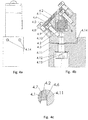
- FIG. 4a The mount for temperature stabilization of optical componets is shown in figures 4a, 4b and 4c .
- a holder 4.3 is installed onto a housing 4.11, wherein the holder has a cavity for a screw 4.12 with a spring washer 4.13.
- an optical element 4.1 is installed into a triangular cavity of the holder 4.3 and onto heat conductive brackets 4.2 .
- the heater 4.4 is attached with screws 4.8 to the pressing cover of the mount 4.5.
- the latter is in contact with heat conductive brackets 4.2 that heat the optical element 4.1 through the indium foil 4.7.
- An appropriate mounting force is ensured through screws 4.9 and coil spring 4.10.
- the thermally active part which includes the optical element 4.1, heat conductive brackets 4.2, the heater 4.4, the pressing cover 4.5 and the foil 4.7 is insulated against other mechanics through steel balls 4.6, which are in point contact with brackets 4.2 and the holder 4.3.
- the holder 4.3 is attached to the housing 4.11 through a screw 4.12 and disc spring 4.13.
- Screw 4.12 axis represents the axis of adjustment
- disc spring 4.13 reduces the backlash in the direction of the screw 4.12 axle
- thermal insulation of the bracket holder against the housing is enabled with point or line contacts 4.6.
- a rotation around the screw 4.12 axis is done with adjustment screws 4.14, which are perpendicular to the screw 4.12. Adjustment is done with screwing one and simultaneously unscrewing the other screw. When the system is adjusted, both adjusting screws are tightened so that the backlash of the mechanics is reduced.
- a combination of point contacts as shown in figure 4c and material with low thermal conductivity for the holder 4.3 is used for thermal insulation of the thermally active part.
- the holder 4.3 is additionally thermally insulated against the housing 4.11 with point contacts 4.6.
- the pressing force, with which the optical element 4.1 is compressed, is defined with deformation of coil springs 4.10.
- the technical solution of the mount for temperature stabilization of optical components according to the invention ensures improved response times and solution flexibility. Improved response times are possible due to the decreased volume of mechanical components.
- the flexibility of the solution most importantly reflects in the miniaturization of the assembly, in the possibility of its use for optical components with different geometries, in the possibility of mounting miniaturized heaters and in the possibility of simple adjustment of the entire assembly.
Landscapes
- Physics & Mathematics (AREA)
- Optics & Photonics (AREA)
- Electromagnetism (AREA)
- General Physics & Mathematics (AREA)
- Engineering & Computer Science (AREA)
- Plasma & Fusion (AREA)
- Lasers (AREA)
- Optical Modulation, Optical Deflection, Nonlinear Optics, Optical Demodulation, Optical Logic Elements (AREA)
- Semiconductor Lasers (AREA)
Description
- The present invention relates to optoelectronic laser devices, more precisely it relates to a mount for optical components with an emphasis on its temperature stabilization and adjustment.
- The technical problem, which is solved by the present invention, is how to ensure improved responsiveness of temperature stabilization of optical components, how to simplify their adjustment and in addition provide miniaturization and cost optimization of the optomechanical assembly while avoiding excessive or uneven thermal loads of optical components.
- Stability of optical components in optoelectronic devices is the weak point of laser devices due to physical characteristics and due to frequent and rapid changes in temperature of their environment. Thermal changes may trigger thermooptic effects, as well as thermomechanical movements, which result in generation of mechanical stresses in material. It is important to keep the optical element at appropriate working temperature in order to ensure improved response times of temperature stabilization, to reduce movements caused by the heat and to avoid heat loads, while at the same time a stable mechanical location is maintained.
- Examples of heavily heat loaded optical components in solid state laser sources are laser rod and crystal for second harmonic generation. In such optical components a part of pumped energy is transformed into heat, which is conductively transported onto the mechanical mount of the optical component. In order to prevent thermomechanical stresses it is crucial to ensure uniform removal of the heat from the entire side surfaces of the optical component. In addition, good temperature responsiveness of the optomechanic assembly is important, which can be achieved by miniaturization of the volume of the entire mechanical mount.
- In the specific example of temperature stabilization of optical components, in which there are no large thermal loads and in which only stable temperature is important for optimal functioning, merely heating of the optical element to a fixed temperature is sufficient. The typical example of such application is temperature stabilization of crystals for second harmonic generation in systems for selective laser trabeculoplasty. In this case, it is important to stabilize only the environmental temperature in order to ensure stable frequency doubling. The most economical way to do this is to heat the crystal to a fixed temperature, which must be higher than the working temperature range of the final system. In this case uniform heating of the crystal is important for good response times of temperature stabilization and for a uniform transverse temperature profile of the optical component.
-
US patent application no. 2004/0165625 discloses a solution, in which the upper V block is additionally held by a spring, which decreases the risk of damaging the optical element due to temperature expansions. The main deficiency of this solution is the loss of thermal contact between the contact blocks and the holder, when the thermal expansion pushes the upper V block. - Patent application
US2008/0247431 discloses a technical solution based on two springs, which allow sliding of the contact blocks, wherein two surfaces are in contact with the tempered part, while two surfaces are indirectly thermally connected. The main deficiencies of this solution are high thermal inertia and slower response times of the holder, which is based on at least three mechanical blocks, as well as non-flexibility of the solution, which does not allow thermal stabilization of optical components from the side of contact blocks. Additionally, this solution enables only mounting of optical elements having rectangular cross-section. - Further pertinent prior art is disclosed in
US 5 935 467 A ,EP 1 999 826 A1 ,US 8 298 335 B2 ,JP 2013 016678 A EP 1 189 101 A1 . - Because known solutions do not completely solve the problem of required responsiveness of temperature stability of the mount holding an optical element, the present invention improves temperature stabilization of an optical component by decreasing the volume of mechanics of the optical component mount. The invention is defined in the appended claims.
- The essence of the mount for temperature stabilization of optical components lies in the fact that improved temperature responsiveness of the optomechanic assembly is achieved together with ensuring uniform heat supply or removal from the entire side surfaces of the optical element by decreasing the volume of a thermally active part of the mount and by placing heat conductive brackets so that they surround the optical element. In addition, the thermally active part of the mount may be disconnected from the thermally inactive part of the mount with point or linear contacts, or the thermally active part can be made of a material with high thermal conductvity, while the thermally inactive part can be made of a material with low thermal conductivity.
- Simplification of the described mount for temperature stabilization of optical components represents a solution, according to which the mount of the optical component is constructed as a single piece. Additional simplification of the mount for temperature stabilization of optical components is enabled in case optical components have a cylindrical shape, in which the mechanical mount made from one piece can also function as a heat conductive bracket.
- For a further understanding of the mount for temperature stabilization of optical components according to the invention, reference should be made to the following detailed disclosure, taken in conjunction with the accompanying figures, which show:
- Figure 1a
- mount for temperature stabilization of optical components according to the invention
- Figure 1b
- mount for temperature stabilization of optical components according to variant I
- Figure 1c
- mount for temperature stabilization of optical components according to variant II
- Figure 1d
- mount for temperature stabilization of optical components according to variant III
- Figure 2
- explosion image of the mount for temperature stabilization of optical components according to the variant represented in
figure 1a - Figure 3
- heating element for stabilization of optical components
- Figure 4a
- side view of the mount for temperature stabilization of optical components
- Figure 4b
- mount for temperature stabilization of optical components
- Figure 4c
- detail B
- The mount for temperature stabilization of optical components has an optical element a1, which is around the greater part of the perimeter surrounded by two heat conductive brackets a2 and a3, and is installed into a rectangular cavity of a holder a4, which is closed by a pressing cover a5 with a heating element a6. The holder a4 is made of a material with low thermal conductivity, while the pressing cover a5 of the holder is made of a material with high thermal conductivity. Label a7 denotes a thermally active part of the mount, which is disconnected from the thermally inactive part, which allows decreasing of the volume of the thermally active mount and consequently improvement of response times of the entire assembly for temperature stabilization of the optical component. Brackets a2 and a3 are thermally regulated through the heating/cooling element a6 on the upper pressing cover a5. Heat conduction in case of the heating of the optical element a1 is represented by arrows in
figure 1a . Brackets a2 and a3 are designed to be adapted to the shape of the optical element a1 on one side, and to the pressing cover a5 and the holder a4 with steel balls a8 on the other side. Between brackets a2 and a3 and the optical element a1 or between brackets a2 and a3 and the pressing cover a5 an indium foil may be placed, which enables more uniform distribution of pressure on the optical element and thereby increases the contact surface between the optical element and heat conductive brackets or between brackets and the pressing cover a5, respectively. The heat is conductively transported through conductive brackets a2 and a3, which uniformly heat the optical element on all four side surfaces. The thermally active part a7 is outlined with a dashed line onfigure 1a and includes the optical element a1, brackets a2 and a3, the pressing cover a5 and the heating/cooling element a6. Simplification of the solution is enabled in the way that there are no point or line contacts between the holder and the brackets, wherein a partial disconnection between the thermally inactive and thermally active part of the mount is enabled by the holder made of a material with low thermal conductivity. This solution is preferably suitable for applications of temperature stabilization of optical components, which do not have large thermal loads. An example of such application is temperature stabilization of crystals for second harmonic generation in a system for selective laser trabeculoplasty. Due to small thermal loading of the optical component this solution also allows a variant, in which the holder can be made out of a material with high thermal conductivity, but this decreases the response time of the optomechanic assembly. - The mount for temperature stabilization of optical components according to variant I has an optical element b1, which is around the greater part of the perimeter surrounded by heat conductive brackets b2 and b3 and is installed into a rectangular cavity of a holder b5 with a heating/cooling element b6, which is closed by a pressing cover b4 of the mount. The holder b5 is made of a material with high thermal conductivity, while the pressing cover b4 is made of a material with low thermal conductivity. Label b7 denotes a thermally active part of the mount, which is disconnected from the thermally inactive part. This solution is also suitable in cases of thermal stabilization of optical components that are more heavily loaded as in the case of temperature stabilization of laser rods in laser resonator. The thermally active part is in
figure 1b outlined with a dashed line and includes the optical element b1, brackets b2 and b3, the holder b5 and the heating/cooling element b6. This solution allows integration of larger or heavier heating/cooling systems. - The optical element a1 is around the greater part of the perimeter surrounded by two heat conductive brackets a2 and a3 with a typical thickness of 1mm, which allows uniform thermal distribution. Disconnection between the thermally active part a7 and the thermally inactive part enables physically smaller thermally active part of the mount, which consequently improves response time of the entire mount. The same also applies for the optical element b1. Decreased heat transfer to the thermally inactive part of the mount is achieved by installing point or line contacts, which are shown by the detail in the
figure 4c . As shown infigure 2 , steel balls may be used for point contacts, whereas cylinders may be used for line contacts. Heat distribution in the optical component is improved if the mechanics of the thermally active part, to which the temperature regulation is attached, is made of a material with high thermal conductivity, while the thermally inactive part is made of a material with low thermal conductivity for example from combination copper/stainless steel, which can partly replace the function of point or line contacts. In addition, between the brackets and the optical element as well as between the brackets and a good thermally conductive part of the assembly a soft, highly heat conductive foil, for example indium foil, can be placed, which deforms under load and allows more uniform distribution of the pressure load and at the same time increases the contact surface for heat transfer. In both solutions 1a and 1b the appropriate mounting force of the optical component is ensured by screws 4.9 and a coil spring 4.10. - Mount for temperature stabilization of optical components according to variant II has a rectangularly shaped optical element c1, which is around the greater part of the perimeter surrounded by two heat conductive brackets c2 and c3 and is installed into a cylindrical cavity of holder c4, which is designed so that it has a cylindrical opening in the middle, and a slot c4'" between the lower part of the holder c4' and the upper part of the holder c4". Perpendicularly through the holder part c4', holder part c4" and the heating element c5 is a bore, into which a screw c7 with a spring washer c6 is mounted, compressing together the holder part c4', the holder part c4" and the heating element c5. The holder c4 is made of a material with high thermal conductivity. In case of integration of larger heating/cooling elements the latter can be added to the lower side of the holder c4, which allows installation of a suitable heat sink.
- Mount for temperature stabilization of optical components according to variant III has a cylindrically shaped optical element d1, which is installed into the cavity of the holder d2 made of a material with high thermal conductivity, and which is shaped so that it has a cylindrical opening in the middle, and a slot d2'" between the lower part of the holder d2' and the upper part of the holder d2". Perpendicularly through the holder part d2', holder part d2" and the heating element d5 a bore is located, into which a screw d3 with a spring washer d5 is mounted, compressing together the holder part d2', the holder part d2" and the heating element d4. Spring washers d5 are used in order to ensure possibility of optical component expanding/shrinking when thermally loaded and to ensure a controlled loading of the optical component during assemby. The optical element d1 is installed with a loose fitting into an elastic clamp of the holder d2, which is made of a material with high thermal conductivity. With tightening of the screw d3 the elastic clamp of the holder d2 is deformed through a spring and the optical element is compressed through the indium foil. This allows a stable mechanic position of the optical component as well as a good thermal contact around the circumference, which still allows temperature expansion of the component. In case of integration of a larger heating/cooling elements the latter can be added to the lower side of the holder d2, which allows installation of a suitable heat sink.
- The mount for temperature stabilization of optical components according to variant II has only the thermally active part and two heat conductive brackets, which means that due to the simplified construction solution there is no need for a thermally inactive part of the mount and consequently installation of point or line contacts. In case of cylindrical optical components the entire solution is additionally simplified by construction of the holder from a single piece according to variant III, according to which its constructional solution makes the thermally inactive part and heat conductive brackets unnecessary, as shown in
figure 1d . The base part of the holder is made of a material with high thermal conductivity and is designed in a such way that the optical element is installed into a cylindrical opening, which allows elastic mounting. The optical element d1 is inserted into the holder d2 and is then fixed with the help of a screw. Due to the elastic and also possible plastic deformation, the clamp embraces the optical element, thereby fixing it, so that uniform heat conduction is enabled throughout the barrel surface. A thin, soft, heat conductive foil may be added between the clamp and the optical component. - Solutions shown in
figures 1a, 1b ,1c and 1d allow additional optimization of heat conduction and improved response times of the system for heating of the optical component to a fixed temperature with the help of a heating element, which is shown infigure 3 . Heaters 3.2 and a temperature sensor 3.3 are soldered to the heat conductive print 3.1. Consequently the print 3.1 functions as a small self-regulating heater with uniformly distributed temperature, which also allows easy mechanical installation. - Constructions shown in
figures 1a ,1c and 1d are particularly suitable for solutions in which adjustment or miniaturization of the mechanical assembly is required. All solutions allow installation of the heating/cooling element onto the pressing cover of the assembly, while the holder is not in contact with the remaining mechanical construction, which enables simple execution of the entire assembly adjustment, wherein the assembly is thermally disconnected from the remaining mechanical construction. Assembly adjustment will be further explained based on the solution shown infigure 1a . - Based on the solution shown in
figure 1a , the following text describes installation of the mount of optical components, which can be applied to all previously mentioned mount variants. The mount for temperature stabilization of optical componets is shown infigures 4a, 4b and 4c . A holder 4.3 is installed onto a housing 4.11, wherein the holder has a cavity for a screw 4.12 with a spring washer 4.13. Into a triangular cavity of the holder 4.3 and onto heat conductive brackets 4.2 an optical element 4.1 is installed. - The heater 4.4 is attached with screws 4.8 to the pressing cover of the mount 4.5. The latter is in contact with heat conductive brackets 4.2 that heat the optical element 4.1 through the indium foil 4.7. An appropriate mounting force is ensured through screws 4.9 and coil spring 4.10. The thermally active part, which includes the optical element 4.1, heat conductive brackets 4.2, the heater 4.4, the pressing cover 4.5 and the foil 4.7 is insulated against other mechanics through steel balls 4.6, which are in point contact with brackets 4.2 and the holder 4.3. The holder 4.3 is attached to the housing 4.11 through a screw 4.12 and disc spring 4.13. Screw 4.12 axis represents the axis of adjustment, disc spring 4.13 reduces the backlash in the direction of the screw 4.12 axle, thermal insulation of the bracket holder against the housing is enabled with point or line contacts 4.6. A rotation around the screw 4.12 axis is done with adjustment screws 4.14, which are perpendicular to the screw 4.12. Adjustment is done with screwing one and simultaneously unscrewing the other screw. When the system is adjusted, both adjusting screws are tightened so that the backlash of the mechanics is reduced.
- A combination of point contacts as shown in
figure 4c and material with low thermal conductivity for the holder 4.3 is used for thermal insulation of the thermally active part. The holder 4.3 is additionally thermally insulated against the housing 4.11 with point contacts 4.6. The pressing force, with which the optical element 4.1 is compressed, is defined with deformation of coil springs 4.10. - Mount for temperature stabilization of optical components allows its integration into a device and its adjustment with the help of three screws.
- The technical solution of the mount for temperature stabilization of optical components according to the invention ensures improved response times and solution flexibility. Improved response times are possible due to the decreased volume of mechanical components. The flexibility of the solution most importantly reflects in the miniaturization of the assembly, in the possibility of its use for optical components with different geometries, in the possibility of mounting miniaturized heaters and in the possibility of simple adjustment of the entire assembly.
Claims (6)
- A mount for temperature stabilization of optical components with improved temperature responsiveness of an optomechanic assembly together with uniform heat supply or removal from the entire side surfaces of the optical component, comprising- an optical element (a1, b1),- a holder (a4, b5),- a pressing cover (a5, b4),- a rectangular cavity, which is formed by a triangular cavity of the holder (a4, b5) and a triangular cavity of the pressing cover (a5, b4), wherein the rectangular cavity receives the optical element (a1, b1),- heat conductive brackets (a2 and a3; b2 and b3), which surround the majority of the perimeter of the optical element (a1, b1) and are adapted to the shape of the optical element (a1, b1) and the holder (a4, b5) and the pressing cover (a5, b4),- a heating/cooling element (a6, b6), which thermally regulates the heat conductive brackets (a2 and a3, b2 and b3),characterized in that
the holder (a4, b5) and the pressing cover (a5, b4) are made of a material with different thermal conductivity;
that when the holder (a4, b5) is made of a material with high thermal conductivity, then the pressing cover (a5, b4) is made of a material with low thermal conductivity, thereby the holder (a4, b5) becoming a thermally active part and the pressing cover (a5, b4) thermally inactive part, the thermally active part also including the optical element (a1, b1), the heat conductive brackets (a2 and a3, b2 and b3) and the heating/cooling element (a6, b6);;
that when the holder (a4, b5) is made of a material with low thermal conductivity, then the pressing cover (a5, b4) is made of a material with high thermal conductivity, thereby the holder (a4, b5) becoming a thermally inactive part and the pressing cover (a5, b4) a thermally active part, the thermally active part also including the optical element (a1, b1), the heat conductive brackets (a2 and a3, b2 and b3) and the heating/cooling element (a6, b6);
that the thermally active part and the thermally inactive part are disconnected with point or line contacts (a8) placed between said thermally active part and said thermally inactive part, wherein the point contacts are steel balls and line contacts are cylinders. - The mount according to claim 1, characterized in that the heating/cooling element (a6) is installed into the holder (a4, b5) or into the pressing cover (a5, b4).
- The mount according to any of the preceding claims, characterized in that an indium foil can be placed between heat conductive brackets (a2, and a3, b2 and b3) and the optical element (a1, b1) or between heat conductive brackets(a2, and a3, b2 and b3) and the pressing cover (a5, b4).
- The mount according to any of the preceding claims, characterized in that when heating of the optical components to a fixed temperature additional optimization of heat conduction and improved response times are achieved with the heating element consisting of heating elements (3.2) and a temperature sensor (3.3), which are soldered to a heat conductive print (3.1) with high thermal conductivity.
- Method for installation and adjustment of the mount according to any of the preceding claims into a device, the method comprising the following steps:- the holder (a4, b5, 4.3) is installed onto housing (4.11) for the mount, wherein the holder has a cavity for a screw (4.12) with a spring washer (4.13);- the optical element (a1, b1, 4.1) is installed into the triangular cavity of the holder (a4, b5, 4.3) and onto heat conductive brackets (a2 and a3, b2 and b3, 4.2);- the heater (a6, b6, 4.4) is tightened with screws (4.8) to the pressing cover (a5, b4, 4.5) of the mount;- the pressing cover (a5, b4, 4.5) of the mount is in contact with heat conductive brackets (a2 and a3, b2 and b3, 4.2) that heat the optical element (a1, b1, 4.1) through the indium foil (4.7);- an appropriate mounting force is ensured through screws (4.9) and a coil spring (4.10)- the thermally active part, which includes the optical element (4.1) heat conductive brackets (a2 and a3, b2 and b3, 4.2), the heater (a6, b6, 4.4), the indium foil (4.7) and the holder (a4, b5, 4.3) or the pressing cover (a5, b4, 4.5) depending on the material from which they are made, is insulated against other mechanics through steel balls (a8, 4.6), which are in point contact with brackets (a2 and a3, b2 and b3, 4.2) and the holder (a4, b5, 4.3);- the holder (a4, b5, 4.3) is attached through a screw (4.12) and a disc spring (4.13) to the housing (4.11);- the screw (4.12) axis represents the axis of adjustment, disc spring (4.13) reduces the backlash in the direction of the screw (4.12) axis, thermal insulation of the bracket holder against the housing is made through point or line contacts (a8, 4.6);- rotation around the screw (4.12) axis is made with adjustment screws (4.14), which are perpendicular to the screw (4.12); and- the adjustment coincides with tightening one and untightening the other screw.
- The method according to claim 5, characterized in that adjustment of the mount according to any claim from 1 to 4 is done with three adjusting screws.
Priority Applications (1)
| Application Number | Priority Date | Filing Date | Title |
|---|---|---|---|
| SI201530979T SI3105628T1 (en) | 2014-02-12 | 2015-02-10 | A mount for temperature stabilization of optical components |
Applications Claiming Priority (2)
| Application Number | Priority Date | Filing Date | Title |
|---|---|---|---|
| SI201400054A SI24642A (en) | 2014-02-12 | 2014-02-12 | A bracket for temperature stabilisation of optical components |
| PCT/SI2015/000005 WO2015122854A2 (en) | 2014-02-12 | 2015-02-10 | A mount for temperature stabilization of optical components |
Publications (2)
| Publication Number | Publication Date |
|---|---|
| EP3105628A2 EP3105628A2 (en) | 2016-12-21 |
| EP3105628B1 true EP3105628B1 (en) | 2019-09-18 |
Family
ID=53005618
Family Applications (1)
| Application Number | Title | Priority Date | Filing Date |
|---|---|---|---|
| EP15718637.0A Active EP3105628B1 (en) | 2014-02-12 | 2015-02-10 | A mount for temperature stabilization of optical components |
Country Status (3)
| Country | Link |
|---|---|
| EP (1) | EP3105628B1 (en) |
| SI (2) | SI24642A (en) |
| WO (1) | WO2015122854A2 (en) |
Families Citing this family (2)
| Publication number | Priority date | Publication date | Assignee | Title |
|---|---|---|---|---|
| DE102016202028B4 (en) | 2016-02-11 | 2017-12-07 | Trumpf Laser Gmbh | Holder for a wavelength conversion crystal and optical system with such a holder |
| CN118040435B (en) * | 2024-03-04 | 2024-11-05 | 齐鲁中科光物理与工程技术研究院 | Quick stable temperature control device for frequency doubling crystal |
Family Cites Families (7)
| Publication number | Priority date | Publication date | Assignee | Title |
|---|---|---|---|---|
| US5935467A (en) * | 1997-05-14 | 1999-08-10 | General Electric Company | Oven for heating a crystal for a laser frequency conversion |
| JP3389197B2 (en) * | 2000-04-19 | 2003-03-24 | 三菱重工業株式会社 | Laser wavelength converter |
| JP2007171491A (en) * | 2005-12-21 | 2007-07-05 | Toshiba Corp | Optical crystal holding structure and wavelength converter |
| FR2899033B1 (en) * | 2006-03-24 | 2008-05-09 | Thales Sa | LASER AMPLIFICATION DEVICE WITH CRYOGENIC COOLING |
| US8298335B2 (en) * | 2007-12-18 | 2012-10-30 | Kla-Tencor Technologies Corporation | Enclosure for controlling the environment of optical crystals |
| JP5729869B2 (en) * | 2011-07-05 | 2015-06-03 | 株式会社日本自動車部品総合研究所 | Solid laser fixing method and laser ignition device using the same |
| US8989224B2 (en) * | 2011-08-22 | 2015-03-24 | Korea Electrotechnology Research Institute | Apparatus for femtosecond laser optically pumped by laser diode pumping module |
-
2014
- 2014-02-12 SI SI201400054A patent/SI24642A/en active IP Right Grant
-
2015
- 2015-02-10 WO PCT/SI2015/000005 patent/WO2015122854A2/en not_active Ceased
- 2015-02-10 EP EP15718637.0A patent/EP3105628B1/en active Active
- 2015-02-10 SI SI201530979T patent/SI3105628T1/en unknown
Non-Patent Citations (1)
| Title |
|---|
| None * |
Also Published As
| Publication number | Publication date |
|---|---|
| EP3105628A2 (en) | 2016-12-21 |
| WO2015122854A3 (en) | 2015-10-15 |
| SI3105628T1 (en) | 2019-12-31 |
| SI24642A (en) | 2015-08-31 |
| WO2015122854A2 (en) | 2015-08-20 |
Similar Documents
| Publication | Publication Date | Title |
|---|---|---|
| US11264305B2 (en) | Heat sink load balancing apparatus | |
| US7193851B2 (en) | Assemblies for holding heat sinks and other structures in contact with electronic devices and other apparatuses | |
| US8038117B2 (en) | Supporting mechanism for electronic device | |
| US6545352B1 (en) | Assembly for mounting power semiconductive modules to heat dissipators | |
| US7080989B2 (en) | Memory metal springs for heatsink attachments | |
| US8988880B2 (en) | Heat transfer assembly with heat pipe brace and method for assembling a heat transfer assembly | |
| US6552905B2 (en) | Heat sink retention apparatus | |
| WO2015122854A2 (en) | A mount for temperature stabilization of optical components | |
| US7345572B2 (en) | Temperature sensor | |
| HK1218218A1 (en) | Method and system for attachment of a heat sink to a circuit board | |
| US20210183742A1 (en) | Pressure controllable encapsulated liquid thermal interface | |
| KR20020024544A (en) | Heater module and optical waveguide module | |
| KR101738069B1 (en) | Flexible display device having shape memory alloy | |
| CN104871057B (en) | Low wavefront distortion optics mounting base | |
| JP6109547B2 (en) | LED light emitting device | |
| US20240334589A1 (en) | Dynamic control of heat sink pressure | |
| US12035499B2 (en) | Stability appliance for securing circuit boards in harsh environments | |
| CN215266439U (en) | Battery temperature adjusting assembly, battery and heat conducting block | |
| JP3726743B2 (en) | Thermal resistance control device | |
| CN210866048U (en) | Double-pin liquid expansion type temperature controller | |
| CN203951727U (en) | A kind of bracing or strutting arrangement of radiator and there is its electronic installation | |
| JP2019075443A (en) | Thermal treatment equipment and support component of processed material for use therein | |
| JP6905818B2 (en) | Temperature control unit and laser light source device | |
| CN217502203U (en) | Heating device | |
| US7277292B2 (en) | Expandable bracing apparatus and method |
Legal Events
| Date | Code | Title | Description |
|---|---|---|---|
| PUAI | Public reference made under article 153(3) epc to a published international application that has entered the european phase |
Free format text: ORIGINAL CODE: 0009012 |
|
| STAA | Information on the status of an ep patent application or granted ep patent |
Free format text: STATUS: REQUEST FOR EXAMINATION WAS MADE |
|
| 17P | Request for examination filed |
Effective date: 20160729 |
|
| AK | Designated contracting states |
Kind code of ref document: A2 Designated state(s): AL AT BE BG CH CY CZ DE DK EE ES FI FR GB GR HR HU IE IS IT LI LT LU LV MC MK MT NL NO PL PT RO RS SE SI SK SM TR |
|
| AX | Request for extension of the european patent |
Extension state: BA ME |
|
| DAX | Request for extension of the european patent (deleted) | ||
| GRAP | Despatch of communication of intention to grant a patent |
Free format text: ORIGINAL CODE: EPIDOSNIGR1 |
|
| STAA | Information on the status of an ep patent application or granted ep patent |
Free format text: STATUS: GRANT OF PATENT IS INTENDED |
|
| INTG | Intention to grant announced |
Effective date: 20190618 |
|
| GRAS | Grant fee paid |
Free format text: ORIGINAL CODE: EPIDOSNIGR3 |
|
| GRAA | (expected) grant |
Free format text: ORIGINAL CODE: 0009210 |
|
| STAA | Information on the status of an ep patent application or granted ep patent |
Free format text: STATUS: THE PATENT HAS BEEN GRANTED |
|
| AK | Designated contracting states |
Kind code of ref document: B1 Designated state(s): AL AT BE BG CH CY CZ DE DK EE ES FI FR GB GR HR HU IE IS IT LI LT LU LV MC MK MT NL NO PL PT RO RS SE SI SK SM TR |
|
| REG | Reference to a national code |
Ref country code: GB Ref legal event code: FG4D |
|
| REG | Reference to a national code |
Ref country code: CH Ref legal event code: EP |
|
| REG | Reference to a national code |
Ref country code: DE Ref legal event code: R096 Ref document number: 602015038191 Country of ref document: DE |
|
| REG | Reference to a national code |
Ref country code: AT Ref legal event code: REF Ref document number: 1182011 Country of ref document: AT Kind code of ref document: T Effective date: 20191015 |
|
| REG | Reference to a national code |
Ref country code: IE Ref legal event code: FG4D |
|
| REG | Reference to a national code |
Ref country code: CH Ref legal event code: NV Representative=s name: DR. LUSUARDI AG, CH |
|
| REG | Reference to a national code |
Ref country code: NL Ref legal event code: MP Effective date: 20190918 |
|
| PG25 | Lapsed in a contracting state [announced via postgrant information from national office to epo] |
Ref country code: FI Free format text: LAPSE BECAUSE OF FAILURE TO SUBMIT A TRANSLATION OF THE DESCRIPTION OR TO PAY THE FEE WITHIN THE PRESCRIBED TIME-LIMIT Effective date: 20190918 Ref country code: BG Free format text: LAPSE BECAUSE OF FAILURE TO SUBMIT A TRANSLATION OF THE DESCRIPTION OR TO PAY THE FEE WITHIN THE PRESCRIBED TIME-LIMIT Effective date: 20191218 Ref country code: NO Free format text: LAPSE BECAUSE OF FAILURE TO SUBMIT A TRANSLATION OF THE DESCRIPTION OR TO PAY THE FEE WITHIN THE PRESCRIBED TIME-LIMIT Effective date: 20191218 Ref country code: SE Free format text: LAPSE BECAUSE OF FAILURE TO SUBMIT A TRANSLATION OF THE DESCRIPTION OR TO PAY THE FEE WITHIN THE PRESCRIBED TIME-LIMIT Effective date: 20190918 Ref country code: HR Free format text: LAPSE BECAUSE OF FAILURE TO SUBMIT A TRANSLATION OF THE DESCRIPTION OR TO PAY THE FEE WITHIN THE PRESCRIBED TIME-LIMIT Effective date: 20190918 Ref country code: LT Free format text: LAPSE BECAUSE OF FAILURE TO SUBMIT A TRANSLATION OF THE DESCRIPTION OR TO PAY THE FEE WITHIN THE PRESCRIBED TIME-LIMIT Effective date: 20190918 |
|
| REG | Reference to a national code |
Ref country code: LT Ref legal event code: MG4D |
|
| PG25 | Lapsed in a contracting state [announced via postgrant information from national office to epo] |
Ref country code: AL Free format text: LAPSE BECAUSE OF FAILURE TO SUBMIT A TRANSLATION OF THE DESCRIPTION OR TO PAY THE FEE WITHIN THE PRESCRIBED TIME-LIMIT Effective date: 20190918 Ref country code: LV Free format text: LAPSE BECAUSE OF FAILURE TO SUBMIT A TRANSLATION OF THE DESCRIPTION OR TO PAY THE FEE WITHIN THE PRESCRIBED TIME-LIMIT Effective date: 20190918 Ref country code: RS Free format text: LAPSE BECAUSE OF FAILURE TO SUBMIT A TRANSLATION OF THE DESCRIPTION OR TO PAY THE FEE WITHIN THE PRESCRIBED TIME-LIMIT Effective date: 20190918 Ref country code: GR Free format text: LAPSE BECAUSE OF FAILURE TO SUBMIT A TRANSLATION OF THE DESCRIPTION OR TO PAY THE FEE WITHIN THE PRESCRIBED TIME-LIMIT Effective date: 20191219 |
|
| REG | Reference to a national code |
Ref country code: AT Ref legal event code: MK05 Ref document number: 1182011 Country of ref document: AT Kind code of ref document: T Effective date: 20190918 |
|
| PG25 | Lapsed in a contracting state [announced via postgrant information from national office to epo] |
Ref country code: RO Free format text: LAPSE BECAUSE OF FAILURE TO SUBMIT A TRANSLATION OF THE DESCRIPTION OR TO PAY THE FEE WITHIN THE PRESCRIBED TIME-LIMIT Effective date: 20190918 Ref country code: PL Free format text: LAPSE BECAUSE OF FAILURE TO SUBMIT A TRANSLATION OF THE DESCRIPTION OR TO PAY THE FEE WITHIN THE PRESCRIBED TIME-LIMIT Effective date: 20190918 Ref country code: ES Free format text: LAPSE BECAUSE OF FAILURE TO SUBMIT A TRANSLATION OF THE DESCRIPTION OR TO PAY THE FEE WITHIN THE PRESCRIBED TIME-LIMIT Effective date: 20190918 Ref country code: NL Free format text: LAPSE BECAUSE OF FAILURE TO SUBMIT A TRANSLATION OF THE DESCRIPTION OR TO PAY THE FEE WITHIN THE PRESCRIBED TIME-LIMIT Effective date: 20190918 Ref country code: AT Free format text: LAPSE BECAUSE OF FAILURE TO SUBMIT A TRANSLATION OF THE DESCRIPTION OR TO PAY THE FEE WITHIN THE PRESCRIBED TIME-LIMIT Effective date: 20190918 Ref country code: PT Free format text: LAPSE BECAUSE OF FAILURE TO SUBMIT A TRANSLATION OF THE DESCRIPTION OR TO PAY THE FEE WITHIN THE PRESCRIBED TIME-LIMIT Effective date: 20200120 Ref country code: EE Free format text: LAPSE BECAUSE OF FAILURE TO SUBMIT A TRANSLATION OF THE DESCRIPTION OR TO PAY THE FEE WITHIN THE PRESCRIBED TIME-LIMIT Effective date: 20190918 Ref country code: IT Free format text: LAPSE BECAUSE OF FAILURE TO SUBMIT A TRANSLATION OF THE DESCRIPTION OR TO PAY THE FEE WITHIN THE PRESCRIBED TIME-LIMIT Effective date: 20190918 |
|
| PG25 | Lapsed in a contracting state [announced via postgrant information from national office to epo] |
Ref country code: CZ Free format text: LAPSE BECAUSE OF FAILURE TO SUBMIT A TRANSLATION OF THE DESCRIPTION OR TO PAY THE FEE WITHIN THE PRESCRIBED TIME-LIMIT Effective date: 20190918 Ref country code: SM Free format text: LAPSE BECAUSE OF FAILURE TO SUBMIT A TRANSLATION OF THE DESCRIPTION OR TO PAY THE FEE WITHIN THE PRESCRIBED TIME-LIMIT Effective date: 20190918 Ref country code: IS Free format text: LAPSE BECAUSE OF FAILURE TO SUBMIT A TRANSLATION OF THE DESCRIPTION OR TO PAY THE FEE WITHIN THE PRESCRIBED TIME-LIMIT Effective date: 20200224 Ref country code: SK Free format text: LAPSE BECAUSE OF FAILURE TO SUBMIT A TRANSLATION OF THE DESCRIPTION OR TO PAY THE FEE WITHIN THE PRESCRIBED TIME-LIMIT Effective date: 20190918 |
|
| REG | Reference to a national code |
Ref country code: DE Ref legal event code: R097 Ref document number: 602015038191 Country of ref document: DE |
|
| PLBE | No opposition filed within time limit |
Free format text: ORIGINAL CODE: 0009261 |
|
| STAA | Information on the status of an ep patent application or granted ep patent |
Free format text: STATUS: NO OPPOSITION FILED WITHIN TIME LIMIT |
|
| PG2D | Information on lapse in contracting state deleted |
Ref country code: IS |
|
| PG25 | Lapsed in a contracting state [announced via postgrant information from national office to epo] |
Ref country code: DK Free format text: LAPSE BECAUSE OF FAILURE TO SUBMIT A TRANSLATION OF THE DESCRIPTION OR TO PAY THE FEE WITHIN THE PRESCRIBED TIME-LIMIT Effective date: 20190918 Ref country code: IS Free format text: LAPSE BECAUSE OF FAILURE TO SUBMIT A TRANSLATION OF THE DESCRIPTION OR TO PAY THE FEE WITHIN THE PRESCRIBED TIME-LIMIT Effective date: 20200119 |
|
| 26N | No opposition filed |
Effective date: 20200619 |
|
| GBPC | Gb: european patent ceased through non-payment of renewal fee |
Effective date: 20200210 |
|
| REG | Reference to a national code |
Ref country code: BE Ref legal event code: MM Effective date: 20200229 |
|
| PG25 | Lapsed in a contracting state [announced via postgrant information from national office to epo] |
Ref country code: LU Free format text: LAPSE BECAUSE OF NON-PAYMENT OF DUE FEES Effective date: 20200210 Ref country code: MC Free format text: LAPSE BECAUSE OF FAILURE TO SUBMIT A TRANSLATION OF THE DESCRIPTION OR TO PAY THE FEE WITHIN THE PRESCRIBED TIME-LIMIT Effective date: 20190918 |
|
| PG25 | Lapsed in a contracting state [announced via postgrant information from national office to epo] |
Ref country code: IE Free format text: LAPSE BECAUSE OF NON-PAYMENT OF DUE FEES Effective date: 20200210 Ref country code: GB Free format text: LAPSE BECAUSE OF NON-PAYMENT OF DUE FEES Effective date: 20200210 |
|
| PG25 | Lapsed in a contracting state [announced via postgrant information from national office to epo] |
Ref country code: BE Free format text: LAPSE BECAUSE OF NON-PAYMENT OF DUE FEES Effective date: 20200229 |
|
| PG25 | Lapsed in a contracting state [announced via postgrant information from national office to epo] |
Ref country code: TR Free format text: LAPSE BECAUSE OF FAILURE TO SUBMIT A TRANSLATION OF THE DESCRIPTION OR TO PAY THE FEE WITHIN THE PRESCRIBED TIME-LIMIT Effective date: 20190918 Ref country code: MT Free format text: LAPSE BECAUSE OF FAILURE TO SUBMIT A TRANSLATION OF THE DESCRIPTION OR TO PAY THE FEE WITHIN THE PRESCRIBED TIME-LIMIT Effective date: 20190918 Ref country code: CY Free format text: LAPSE BECAUSE OF FAILURE TO SUBMIT A TRANSLATION OF THE DESCRIPTION OR TO PAY THE FEE WITHIN THE PRESCRIBED TIME-LIMIT Effective date: 20190918 |
|
| PG25 | Lapsed in a contracting state [announced via postgrant information from national office to epo] |
Ref country code: MK Free format text: LAPSE BECAUSE OF FAILURE TO SUBMIT A TRANSLATION OF THE DESCRIPTION OR TO PAY THE FEE WITHIN THE PRESCRIBED TIME-LIMIT Effective date: 20190918 |
|
| PGFP | Annual fee paid to national office [announced via postgrant information from national office to epo] |
Ref country code: DE Payment date: 20240226 Year of fee payment: 10 Ref country code: CH Payment date: 20240301 Year of fee payment: 10 |
|
| PGFP | Annual fee paid to national office [announced via postgrant information from national office to epo] |
Ref country code: SI Payment date: 20240223 Year of fee payment: 10 |
|
| PGFP | Annual fee paid to national office [announced via postgrant information from national office to epo] |
Ref country code: FR Payment date: 20240227 Year of fee payment: 10 |
|
| REG | Reference to a national code |
Ref country code: DE Ref legal event code: R119 Ref document number: 602015038191 Country of ref document: DE |
|
| REG | Reference to a national code |
Ref country code: CH Ref legal event code: PL |
|
| PG25 | Lapsed in a contracting state [announced via postgrant information from national office to epo] |
Ref country code: CH Free format text: LAPSE BECAUSE OF NON-PAYMENT OF DUE FEES Effective date: 20250228 |
|
| PG25 | Lapsed in a contracting state [announced via postgrant information from national office to epo] |
Ref country code: DE Free format text: LAPSE BECAUSE OF NON-PAYMENT OF DUE FEES Effective date: 20250902 |
|
| PG25 | Lapsed in a contracting state [announced via postgrant information from national office to epo] |
Ref country code: FR Free format text: LAPSE BECAUSE OF NON-PAYMENT OF DUE FEES Effective date: 20250228 |