EP3105521B1 - Flexible panel and sealable bag with sorbent - Google Patents
Flexible panel and sealable bag with sorbent Download PDFInfo
- Publication number
- EP3105521B1 EP3105521B1 EP15708253.8A EP15708253A EP3105521B1 EP 3105521 B1 EP3105521 B1 EP 3105521B1 EP 15708253 A EP15708253 A EP 15708253A EP 3105521 B1 EP3105521 B1 EP 3105521B1
- Authority
- EP
- European Patent Office
- Prior art keywords
- bag
- impermeable
- inner layer
- cavities
- layer
- Prior art date
- Legal status (The legal status is an assumption and is not a legal conclusion. Google has not performed a legal analysis and makes no representation as to the accuracy of the status listed.)
- Active
Links
- 239000002594 sorbent Substances 0.000 title claims description 48
- 239000007789 gas Substances 0.000 claims description 71
- 239000000463 material Substances 0.000 claims description 54
- 239000000853 adhesive Substances 0.000 claims description 40
- 230000001070 adhesive effect Effects 0.000 claims description 40
- QVGXLLKOCUKJST-UHFFFAOYSA-N atomic oxygen Chemical compound [O] QVGXLLKOCUKJST-UHFFFAOYSA-N 0.000 claims description 29
- 229910052760 oxygen Inorganic materials 0.000 claims description 29
- 239000001301 oxygen Substances 0.000 claims description 29
- 238000000034 method Methods 0.000 claims description 23
- 238000007789 sealing Methods 0.000 claims description 18
- 239000011358 absorbing material Substances 0.000 claims description 12
- 239000010410 layer Substances 0.000 description 210
- 239000002274 desiccant Substances 0.000 description 19
- XLYOFNOQVPJJNP-UHFFFAOYSA-N water Substances O XLYOFNOQVPJJNP-UHFFFAOYSA-N 0.000 description 19
- 238000013459 approach Methods 0.000 description 17
- 239000007788 liquid Substances 0.000 description 17
- IJGRMHOSHXDMSA-UHFFFAOYSA-N Atomic nitrogen Chemical compound N#N IJGRMHOSHXDMSA-UHFFFAOYSA-N 0.000 description 14
- 239000006096 absorbing agent Substances 0.000 description 14
- 239000000126 substance Substances 0.000 description 14
- 238000004519 manufacturing process Methods 0.000 description 13
- 239000010408 film Substances 0.000 description 12
- 230000006870 function Effects 0.000 description 11
- 238000010438 heat treatment Methods 0.000 description 11
- 239000000779 smoke Substances 0.000 description 11
- 230000004071 biological effect Effects 0.000 description 9
- 230000000694 effects Effects 0.000 description 9
- 230000003068 static effect Effects 0.000 description 9
- 238000009833 condensation Methods 0.000 description 8
- 230000005494 condensation Effects 0.000 description 8
- 239000012528 membrane Substances 0.000 description 8
- 238000012544 monitoring process Methods 0.000 description 8
- 239000012190 activator Substances 0.000 description 7
- 229910052757 nitrogen Inorganic materials 0.000 description 7
- 230000037361 pathway Effects 0.000 description 7
- 230000004888 barrier function Effects 0.000 description 6
- 238000004891 communication Methods 0.000 description 6
- 238000011109 contamination Methods 0.000 description 6
- 230000007797 corrosion Effects 0.000 description 6
- 238000005260 corrosion Methods 0.000 description 6
- 238000013461 design Methods 0.000 description 6
- 238000011084 recovery Methods 0.000 description 6
- 230000001105 regulatory effect Effects 0.000 description 6
- 230000009471 action Effects 0.000 description 5
- 239000013043 chemical agent Substances 0.000 description 5
- 238000006243 chemical reaction Methods 0.000 description 5
- 238000000576 coating method Methods 0.000 description 5
- 238000005516 engineering process Methods 0.000 description 5
- 230000007613 environmental effect Effects 0.000 description 5
- 239000002245 particle Substances 0.000 description 5
- -1 polyethylene Polymers 0.000 description 5
- 239000011148 porous material Substances 0.000 description 5
- 230000008569 process Effects 0.000 description 5
- 239000002516 radical scavenger Substances 0.000 description 5
- OKTJSMMVPCPJKN-UHFFFAOYSA-N Carbon Chemical compound [C] OKTJSMMVPCPJKN-UHFFFAOYSA-N 0.000 description 4
- 239000004480 active ingredient Substances 0.000 description 4
- 230000008901 benefit Effects 0.000 description 4
- 239000006227 byproduct Substances 0.000 description 4
- 239000011248 coating agent Substances 0.000 description 4
- 230000007246 mechanism Effects 0.000 description 4
- 238000004806 packaging method and process Methods 0.000 description 4
- 239000011347 resin Substances 0.000 description 4
- 229920005989 resin Polymers 0.000 description 4
- 206010073310 Occupational exposures Diseases 0.000 description 3
- 230000015556 catabolic process Effects 0.000 description 3
- 238000006731 degradation reaction Methods 0.000 description 3
- 238000001914 filtration Methods 0.000 description 3
- 231100000675 occupational exposure Toxicity 0.000 description 3
- 230000000979 retarding effect Effects 0.000 description 3
- 238000009834 vaporization Methods 0.000 description 3
- VEXZGXHMUGYJMC-UHFFFAOYSA-N Hydrochloric acid Chemical compound Cl VEXZGXHMUGYJMC-UHFFFAOYSA-N 0.000 description 2
- WHXSMMKQMYFTQS-UHFFFAOYSA-N Lithium Chemical compound [Li] WHXSMMKQMYFTQS-UHFFFAOYSA-N 0.000 description 2
- 239000004698 Polyethylene Substances 0.000 description 2
- VYPSYNLAJGMNEJ-UHFFFAOYSA-N Silicium dioxide Chemical compound O=[Si]=O VYPSYNLAJGMNEJ-UHFFFAOYSA-N 0.000 description 2
- 238000010521 absorption reaction Methods 0.000 description 2
- 239000002253 acid Substances 0.000 description 2
- 230000002378 acidificating effect Effects 0.000 description 2
- 230000008859 change Effects 0.000 description 2
- 239000004020 conductor Substances 0.000 description 2
- 238000005202 decontamination Methods 0.000 description 2
- 230000003588 decontaminative effect Effects 0.000 description 2
- 238000009826 distribution Methods 0.000 description 2
- 238000000605 extraction Methods 0.000 description 2
- 239000012530 fluid Substances 0.000 description 2
- 238000009472 formulation Methods 0.000 description 2
- 239000001257 hydrogen Substances 0.000 description 2
- 229910052739 hydrogen Inorganic materials 0.000 description 2
- 229910052744 lithium Inorganic materials 0.000 description 2
- 238000005259 measurement Methods 0.000 description 2
- 239000000203 mixture Substances 0.000 description 2
- 239000002808 molecular sieve Substances 0.000 description 2
- 239000004745 nonwoven fabric Substances 0.000 description 2
- 238000007254 oxidation reaction Methods 0.000 description 2
- 230000001590 oxidative effect Effects 0.000 description 2
- 230000035515 penetration Effects 0.000 description 2
- 239000004033 plastic Substances 0.000 description 2
- 229920003023 plastic Polymers 0.000 description 2
- 229920000573 polyethylene Polymers 0.000 description 2
- 229920000139 polyethylene terephthalate Polymers 0.000 description 2
- 239000005020 polyethylene terephthalate Substances 0.000 description 2
- 230000001681 protective effect Effects 0.000 description 2
- 238000005086 pumping Methods 0.000 description 2
- 230000035939 shock Effects 0.000 description 2
- 239000000741 silica gel Substances 0.000 description 2
- 229910002027 silica gel Inorganic materials 0.000 description 2
- URGAHOPLAPQHLN-UHFFFAOYSA-N sodium aluminosilicate Chemical compound [Na+].[Al+3].[O-][Si]([O-])=O.[O-][Si]([O-])=O URGAHOPLAPQHLN-UHFFFAOYSA-N 0.000 description 2
- 238000003860 storage Methods 0.000 description 2
- 239000000758 substrate Substances 0.000 description 2
- 229920001169 thermoplastic Polymers 0.000 description 2
- 239000004416 thermosoftening plastic Substances 0.000 description 2
- 239000010409 thin film Substances 0.000 description 2
- 241000251468 Actinopterygii Species 0.000 description 1
- 241000270722 Crocodylidae Species 0.000 description 1
- DGAQECJNVWCQMB-PUAWFVPOSA-M Ilexoside XXIX Chemical compound C[C@@H]1CC[C@@]2(CC[C@@]3(C(=CC[C@H]4[C@]3(CC[C@@H]5[C@@]4(CC[C@@H](C5(C)C)OS(=O)(=O)[O-])C)C)[C@@H]2[C@]1(C)O)C)C(=O)O[C@H]6[C@@H]([C@H]([C@@H]([C@H](O6)CO)O)O)O.[Na+] DGAQECJNVWCQMB-PUAWFVPOSA-M 0.000 description 1
- XEEYBQQBJWHFJM-UHFFFAOYSA-N Iron Chemical compound [Fe] XEEYBQQBJWHFJM-UHFFFAOYSA-N 0.000 description 1
- FYYHWMGAXLPEAU-UHFFFAOYSA-N Magnesium Chemical compound [Mg] FYYHWMGAXLPEAU-UHFFFAOYSA-N 0.000 description 1
- 230000010718 Oxidation Activity Effects 0.000 description 1
- 239000004952 Polyamide Substances 0.000 description 1
- ZLMJMSJWJFRBEC-UHFFFAOYSA-N Potassium Chemical compound [K] ZLMJMSJWJFRBEC-UHFFFAOYSA-N 0.000 description 1
- 241000700605 Viruses Species 0.000 description 1
- 230000002745 absorbent Effects 0.000 description 1
- 239000002250 absorbent Substances 0.000 description 1
- 230000003213 activating effect Effects 0.000 description 1
- 230000004913 activation Effects 0.000 description 1
- 239000011149 active material Substances 0.000 description 1
- 239000012790 adhesive layer Substances 0.000 description 1
- 239000004411 aluminium Substances 0.000 description 1
- XAGFODPZIPBFFR-UHFFFAOYSA-N aluminium Chemical compound [Al] XAGFODPZIPBFFR-UHFFFAOYSA-N 0.000 description 1
- 229910052782 aluminium Inorganic materials 0.000 description 1
- 239000004599 antimicrobial Substances 0.000 description 1
- 239000010425 asbestos Substances 0.000 description 1
- 230000000712 assembly Effects 0.000 description 1
- 238000000429 assembly Methods 0.000 description 1
- 230000000975 bioactive effect Effects 0.000 description 1
- 239000003518 caustics Substances 0.000 description 1
- 150000001787 chalcogens Chemical group 0.000 description 1
- 239000003795 chemical substances by application Substances 0.000 description 1
- 238000007906 compression Methods 0.000 description 1
- 230000006835 compression Effects 0.000 description 1
- 239000000356 contaminant Substances 0.000 description 1
- 238000012864 cross contamination Methods 0.000 description 1
- 230000003247 decreasing effect Effects 0.000 description 1
- 230000001419 dependent effect Effects 0.000 description 1
- LNNWVNGFPYWNQE-GMIGKAJZSA-N desomorphine Chemical compound C1C2=CC=C(O)C3=C2[C@]24CCN(C)[C@H]1[C@@H]2CCC[C@@H]4O3 LNNWVNGFPYWNQE-GMIGKAJZSA-N 0.000 description 1
- 238000009792 diffusion process Methods 0.000 description 1
- 230000035622 drinking Effects 0.000 description 1
- 239000000428 dust Substances 0.000 description 1
- 230000002708 enhancing effect Effects 0.000 description 1
- 238000001704 evaporation Methods 0.000 description 1
- 230000008020 evaporation Effects 0.000 description 1
- 239000003000 extruded plastic Substances 0.000 description 1
- 238000011049 filling Methods 0.000 description 1
- 239000003517 fume Substances 0.000 description 1
- 230000004927 fusion Effects 0.000 description 1
- 239000003292 glue Substances 0.000 description 1
- 230000005484 gravity Effects 0.000 description 1
- 239000000383 hazardous chemical Substances 0.000 description 1
- 239000013056 hazardous product Substances 0.000 description 1
- 238000007654 immersion Methods 0.000 description 1
- 239000004615 ingredient Substances 0.000 description 1
- 150000002500 ions Chemical class 0.000 description 1
- 239000002648 laminated material Substances 0.000 description 1
- 230000000670 limiting effect Effects 0.000 description 1
- 238000011068 loading method Methods 0.000 description 1
- 229920001684 low density polyethylene Polymers 0.000 description 1
- 239000004702 low-density polyethylene Substances 0.000 description 1
- 239000011777 magnesium Substances 0.000 description 1
- 229910052749 magnesium Inorganic materials 0.000 description 1
- 238000007726 management method Methods 0.000 description 1
- 239000002120 nanofilm Substances 0.000 description 1
- 238000010943 off-gassing Methods 0.000 description 1
- 239000007800 oxidant agent Substances 0.000 description 1
- 230000003647 oxidation Effects 0.000 description 1
- 238000000059 patterning Methods 0.000 description 1
- 239000008188 pellet Substances 0.000 description 1
- 230000000149 penetrating effect Effects 0.000 description 1
- 230000000737 periodic effect Effects 0.000 description 1
- 230000035699 permeability Effects 0.000 description 1
- 239000002984 plastic foam Substances 0.000 description 1
- 229920002647 polyamide Polymers 0.000 description 1
- 229920000728 polyester Polymers 0.000 description 1
- 229920000642 polymer Polymers 0.000 description 1
- 229910052700 potassium Inorganic materials 0.000 description 1
- 239000011591 potassium Substances 0.000 description 1
- 230000003449 preventive effect Effects 0.000 description 1
- 238000007639 printing Methods 0.000 description 1
- 238000012545 processing Methods 0.000 description 1
- 230000002035 prolonged effect Effects 0.000 description 1
- 239000011253 protective coating Substances 0.000 description 1
- 239000011241 protective layer Substances 0.000 description 1
- 102000004169 proteins and genes Human genes 0.000 description 1
- 108090000623 proteins and genes Proteins 0.000 description 1
- 239000011342 resin composition Substances 0.000 description 1
- 229910052895 riebeckite Inorganic materials 0.000 description 1
- 238000009738 saturating Methods 0.000 description 1
- 239000013535 sea water Substances 0.000 description 1
- 229910052708 sodium Inorganic materials 0.000 description 1
- 239000011734 sodium Substances 0.000 description 1
- 238000001179 sorption measurement Methods 0.000 description 1
- 125000006850 spacer group Chemical group 0.000 description 1
- 238000010186 staining Methods 0.000 description 1
- 239000010902 straw Substances 0.000 description 1
- 230000035900 sweating Effects 0.000 description 1
- 230000007704 transition Effects 0.000 description 1
Images


Classifications
-
- B—PERFORMING OPERATIONS; TRANSPORTING
- B01—PHYSICAL OR CHEMICAL PROCESSES OR APPARATUS IN GENERAL
- B01D—SEPARATION
- B01D53/00—Separation of gases or vapours; Recovering vapours of volatile solvents from gases; Chemical or biological purification of waste gases, e.g. engine exhaust gases, smoke, fumes, flue gases, aerosols
- B01D53/02—Separation of gases or vapours; Recovering vapours of volatile solvents from gases; Chemical or biological purification of waste gases, e.g. engine exhaust gases, smoke, fumes, flue gases, aerosols by adsorption, e.g. preparative gas chromatography
- B01D53/04—Separation of gases or vapours; Recovering vapours of volatile solvents from gases; Chemical or biological purification of waste gases, e.g. engine exhaust gases, smoke, fumes, flue gases, aerosols by adsorption, e.g. preparative gas chromatography with stationary adsorbents
- B01D53/0407—Constructional details of adsorbing systems
-
- B—PERFORMING OPERATIONS; TRANSPORTING
- B32—LAYERED PRODUCTS
- B32B—LAYERED PRODUCTS, i.e. PRODUCTS BUILT-UP OF STRATA OF FLAT OR NON-FLAT, e.g. CELLULAR OR HONEYCOMB, FORM
- B32B3/00—Layered products comprising a layer with external or internal discontinuities or unevennesses, or a layer of non-planar shape; Layered products comprising a layer having particular features of form
- B32B3/26—Layered products comprising a layer with external or internal discontinuities or unevennesses, or a layer of non-planar shape; Layered products comprising a layer having particular features of form characterised by a particular shape of the outline of the cross-section of a continuous layer; characterised by a layer with cavities or internal voids ; characterised by an apertured layer
-
- F—MECHANICAL ENGINEERING; LIGHTING; HEATING; WEAPONS; BLASTING
- F26—DRYING
- F26B—DRYING SOLID MATERIALS OR OBJECTS BY REMOVING LIQUID THEREFROM
- F26B5/00—Drying solid materials or objects by processes not involving the application of heat
- F26B5/16—Drying solid materials or objects by processes not involving the application of heat by contact with sorbent bodies, e.g. absorbent mould; by admixture with sorbent materials
-
- B—PERFORMING OPERATIONS; TRANSPORTING
- B01—PHYSICAL OR CHEMICAL PROCESSES OR APPARATUS IN GENERAL
- B01D—SEPARATION
- B01D2257/00—Components to be removed
- B01D2257/10—Single element gases other than halogens
- B01D2257/104—Oxygen
-
- B—PERFORMING OPERATIONS; TRANSPORTING
- B01—PHYSICAL OR CHEMICAL PROCESSES OR APPARATUS IN GENERAL
- B01D—SEPARATION
- B01D2257/00—Components to be removed
- B01D2257/20—Halogens or halogen compounds
- B01D2257/204—Inorganic halogen compounds
- B01D2257/2045—Hydrochloric acid
-
- B—PERFORMING OPERATIONS; TRANSPORTING
- B01—PHYSICAL OR CHEMICAL PROCESSES OR APPARATUS IN GENERAL
- B01D—SEPARATION
- B01D2257/00—Components to be removed
- B01D2257/80—Water
-
- B—PERFORMING OPERATIONS; TRANSPORTING
- B01—PHYSICAL OR CHEMICAL PROCESSES OR APPARATUS IN GENERAL
- B01D—SEPARATION
- B01D2257/00—Components to be removed
- B01D2257/90—Odorous compounds not provided for in groups B01D2257/00 - B01D2257/708
-
- B—PERFORMING OPERATIONS; TRANSPORTING
- B32—LAYERED PRODUCTS
- B32B—LAYERED PRODUCTS, i.e. PRODUCTS BUILT-UP OF STRATA OF FLAT OR NON-FLAT, e.g. CELLULAR OR HONEYCOMB, FORM
- B32B2307/00—Properties of the layers or laminate
- B32B2307/70—Other properties
- B32B2307/724—Permeability to gases, adsorption
- B32B2307/7242—Non-permeable
-
- B—PERFORMING OPERATIONS; TRANSPORTING
- B32—LAYERED PRODUCTS
- B32B—LAYERED PRODUCTS, i.e. PRODUCTS BUILT-UP OF STRATA OF FLAT OR NON-FLAT, e.g. CELLULAR OR HONEYCOMB, FORM
- B32B2307/00—Properties of the layers or laminate
- B32B2307/70—Other properties
- B32B2307/74—Oxygen absorber
-
- B—PERFORMING OPERATIONS; TRANSPORTING
- B32—LAYERED PRODUCTS
- B32B—LAYERED PRODUCTS, i.e. PRODUCTS BUILT-UP OF STRATA OF FLAT OR NON-FLAT, e.g. CELLULAR OR HONEYCOMB, FORM
- B32B2307/00—Properties of the layers or laminate
- B32B2307/70—Other properties
- B32B2307/758—Odour absorbent
-
- B—PERFORMING OPERATIONS; TRANSPORTING
- B32—LAYERED PRODUCTS
- B32B—LAYERED PRODUCTS, i.e. PRODUCTS BUILT-UP OF STRATA OF FLAT OR NON-FLAT, e.g. CELLULAR OR HONEYCOMB, FORM
- B32B2439/00—Containers; Receptacles
- B32B2439/40—Closed containers
- B32B2439/46—Bags
Definitions
- the present invention relates to a sealable bag for use with sorbent material, such as oxygen and moisture absorbers and odour adsorbers.
- the present invention also relates to a method of preserving an item.
- a bag and method are known from JP10250774A .
- the bags may be used for example for fire and flood disaster recovery of electronics equipment, protection of artistic works or preventive protection of household items in the event of a flood.
- Dehumidifiers can be used to reduce moisture levels from whole rooms or buildings, but only water and/or water vapour is removed and the timescale is too long to prevent irrecoverable damage to electronic equipment. Furthermore, in a major flood incident, there can be a scarcity of dehumidifying plant across the whole region affected. Also dehumidifiers and in particular desiccant dehumidifiers can cause Electrostatic Discharge (ESD) problems.
- ESD Electrostatic Discharge
- a known approach to providing a controlled local environment to halt the degradation of electronic equipment that has been subjected to fire or flood is to use a sealable bag.
- UK patent GB2350347 in the name of the applicant discloses a bag for storage of items in a controlled environment.
- the bag is intended for preserving items such as electrical goods placed therein from corrosion, especially following a fire or flood.
- the plastic bag is lined with oxidation arrest paper and has a mouth closeable by a strip seal.
- Valve means in the bag wall may comprise a locking inlet valve through which a moisture displacer may be pumped in, and a locking outlet valve through which air can be extracted from the bag.
- the bag may contain a humidity indicator card and also contain a desiccant such as silica gel.
- a problem with this is that the oxygen absorber is not separated from the electrical equipment in the bag, so it can become damaged and can itself contaminate the electrical equipment.
- US patent application US5739463 in the name of Raychem Corporation discloses sealed electronics packaging for the environmental protection of active electronic circuit boards and the like assemblies.
- An envelope has walls of a laminate material.
- the particular sheet material comprises top and bottom layers of a suitable material such as low density polyethylene about 200 microns thick and two interior layers about 80 microns thick of cast polyamide or polyester and a central layer of about 20 microns thick of aluminium or other suitable material.
- a problem of sharp points extending from the active electronics and puncturing the sheet material was addressed by surrounding the active electronics with an extruded plastic mesh tube with large holes, plastic foam, fish paper, or paper containing desiccant materials. After an electrical connector is engaged a packet of desiccant/scavenger is inserted into the open end of the packaging and the back edge is sealed using a simple heat sealing machine.
- Japanese patent application JP2009040440A in the name of Dainippon Printing Co Ltd discloses an oxygen and moisture absorbing pouch, which uses a moisture absorbing laminated body and an oxygen absorbing laminated body.
- the moisture absorbing laminated body (a) consists of a moisture absorbing nonwoven fabric using a resin carrying a substrate film (i), a barrier thin film layer (ii) and a drying agent (iii).
- the oxygen absorbing laminated body (b) consists of an oxygen absorbing resin film comprising a resin composition comprising a substrate film (i), a barrier thin film layer (ii) and an oxidative resin (iii) or the like.
- the bag (c) is manufactured so that the nonwoven fabric of the moisture absorbing laminated body (a) and the oxygen absorbing resin film of the oxygen absorbing laminated body (b) face each other.
- the laminate is relatively expensive to manufacture. Furthermore, it does not provide oxygen absorbing and moisture absorbing materials on the same wall of the bag. Therefore the oxygen and moisture absorbing functions do not fully surround the electronic equipment.
- Another approach is using packets of desiccant/scavenger.
- the packets are localised in one part of the bag. Therefore the oxygen and moisture absorbing functions do not fully surround the electronic equipment. Furthermore, packets of desiccant/scavenger can slip to the bottom of the bag, ending up in a pool of water, thus saturating them.
- Another problem is that if the bags have different sizes, the then the user would have to calculate or follow instructions to determine how many packets or what size of packet should be added in order to put in the correct amount of absorbing material.
- the impermeable outer layer comprises an aperture for manual rupturing of the impermeable inner layer in use to expose the cavities to the contents of the sealable bag.
- the impermeable outer layer is provided with at least one first adhesive seal around the aperture and the impermeable inner layer is removably adhered to the at least one first adhesive seal to seal the aperture of the impermeable outer layer.
- the impermeable outer layer is provided with a second adhesive seal configurable to seal the aperture of the impermeable outer layer after removal of the impermeable inner layer from the at least one first adhesive seal.
- the flexible panel further comprises sorbent material contained in a plurality of the cavities.
- the sorbent material comprises at least one sorbent selected from the group: moisture absorbing material, oxygen absorbing material and odour adsorbing material.
- the flexible panel further comprises biological activity retardant material contained in a plurality of the cavities.
- At least one permeable inner layer is configured to provide a plurality of channels.
- At least some of the channels are interconnected.
- At least some of the channels are configured to radiate from a port in the outer impermeable layer.
- the flexible panel further comprises tubes arranged in the channels configured to wick moisture along the channels by capillary action.
- the flexible panel further comprises tie rods between a pair of layers in the flexible panel, the tie rods configured to be collapsible in use responsive to a pressure difference across the layers of the flexible panel.
- the flexible panel comprises a plurality of permeable layers with differing pore sizes configured to separate different gasses and or liquids into different respective cavities bounded by the permeable layers with differing pore sizes.
- the flexible panel flexible further comprises one or more electronic components operable to monitor or control a chemical environment in a bag.
- the components are printed onto a layer of the flexible panel.
- the components comprise one or more components selected from the group: a sensor, a conductor, a heater, a processor, a communications transmitter, a communications receiver and a GPS receiver.
- the flexible panel further comprises a flow-regulating outlet port through the outer impermeable layer.
- the flexible panel further comprises an antistatic port through the outer impermeable layer.
- the flexible panel further comprises a condensation release valve in fluid communication with a port through the outer impermeable layer.
- the flexible panel further comprises a thermoplastic tongue member or a thermoplastic groove member of a heat sealable tongue and groove closure.
- the step of manually rupturing the impermeable inner layer comprises manually detaching the impermeable inner layer from the impermeable outer layer to expose the cavities to the item in the sealed bag.
- the method of preserving an item further comprises the step of providing an aperture in the impermeable outer layer, and wherein the step of manually rupturing the impermeable inner layer uses the aperture.
- the method of preserving an item further comprises the steps of:
- the method of preserving an item further comprises the steps of:
- Examples described herein takes in to consideration the mixed chemical reaction that can take place, subsequently enhancing chemical actions and reactions to get the desired effect in addition to allowing for exhaust, collection and control of unwanted by products, through an active working enclosure comprising flexible panels.
- Drying agents tend to clump during the water absorption process, disintegrate or form a syrupy layer.
- the approach described herein tackles this problem by containing sorbents in cavities.
- Examples described herein provide chemical delivery and contamination recovery carried out in an encapsulated device with the integrated option of sensor and microprocessor technology.
- Examples described herein relate to a multifunction device that actively prevents the onset of corrosion, retards biological activity, recovers excess moisture, neutralizes acidic residue, and combats oxidizing chemical agents which are not limited to members of the chalcogen group on the periodic table. This approach is applied to, but not limited to, electronic equipment following and not limited to incidents such as fires or pre and post disaster flooding.
- This bag device having flexible panels works in low moisture environments and high moisture environments.
- Examples described herein have the optional functionality allowing for selective interchangeable layer option to be used based on individual requirements.
- the ports and components can be configured and can be interchanged at manufacturing stage. Sensors can also be placed on to alternative layers at manufacturing stage.
- Examples described herein help to solve the problem of occupational exposure (secondary contamination) of restoration and insurance personal, from exposure to off gassing of smoke damaged items.
- Such bag devices retard corrosion without destroying the items placed inside the device.
- Examples described herein help to solve the problem of occupational exposure of restoration and insurance personal from water damaged items.
- Such bag devices retard biological activity without destroying the items placed inside the device.
- More elaborate examples of the bag may carry out real-time management with constant monitoring through smart sensors, printed directly onto a flexible layer surface using organic and printed electronics technology and communication systems.
- examples described herein provide an active working enclosure, which can be adjusted to change the environment, limiting gaseous by-products, exchanging air, and removing condensation.
- Electronic equipment may be rescued through this active working enclosure resulting in protection from further contamination and degradation of the equipment, due to the threat or possibility of corrosive contamination penetrating the equipment.
- Examples described herein prevent cross contamination by the potentially contaminated items being protected within the enclosure.
- Examples described herein prevent occupational exposure by the potentially contaminated items being protected within the enclosure.
- IP67 ingress rating
- ESD material may be integrated into the material of the flexible panel.
- the flexible panel of the bag wall may have conductive tracks (for example contact strips) affixed to or embedded in it.
- the conductive tracks may be connected to an ESD external 10mm male stud 18, for connection to ESD grounding strap or for static discharge by a handheld static discharge device.
- the conductive tracks may be connected to an internal card (such as the computer 38 with the entire processor being the size of a SD card) that is additionally provided with an ESD removal chip.
- an internal card such as the computer 38 with the entire processor being the size of a SD card
- the conductive tracks may be connected via the electronics connector 31 to an external module (such as the electronics controller module externally mounted outside of the bag) that is additionally provided with an ESD removal chip.
- an external module such as the electronics controller module externally mounted outside of the bag
- Nitrogen may be used to re-inflate the enclosure and for air exchange benefits.
- the flexible panels of the bag may be made of layers of a plastic such as polyethylene (PE). This has the advantage that the layers may be heat sealed together. Thicker gauge polyethylene terephthalate (PET) may also be suitable and may be more puncture-resistant.
- PE polyethylene
- Examples described herein provide ridges or tubes ( Figure 1 , 32) that radiate from the vacuum pull valve ( Figure 1 , 23). This allows for 360° vacuum pull.
- the air release valve feature allows for gas to be sucked in along the whole ridged pathways, which travels across the surface. This feature allows for the release of trapped air. This feature also allows for moisture movement to happen in order for the extraction to be more effective.
- Examples described herein provide internal heating means. This approach allows for bags to incorporate thermal functions to encourage vaporisation of sitting water from the item placed inside the enclosure aided by the optional heat activator 55 by exposing the heat activator to the open bag enclosure.
- the sitting water is warmed up by heat generating material or layers.
- the increase in temperature encourages vaporisation of liquid to gas which is absorbed by the moisture absorbing material more easily.
- the kinetic energy from the heating provides better mass transport of gas within the bag and can also increase the efficiency of the sorption.
- the device can be used in conjunction with a specific heat calculator for exact amount of formulation. External heat trays can be placed outside of the device aiding temperature settings. The temperature inside the enclosure is measured by either an infra-red thermometer or sensors, this measurement along with the mass will give an idea of how much formulation needs to be added.
- Examples described herein provide internal GPS/messaging means for remote monitoring, control and notifications. Examples described herein incorporate a GPS tracking feature that is operational in real-time. Examples described herein incorporate a security and tamper feature that is operational in real-time.
- a regulated outlet functional to prevent damage to equipment being protected by too fast air flow (static) or impulse from deflating bag.
- Inlet and outlet ports are anti-static to reduce static build up in use.
- Relative humidity should be kept within acceptable limits to avoid susceptibility to static charge build up and ESD damage.
- the desiccant can cause such problems by lowering the relative humidity below 10%.
- One way to avoid this problem is by using desiccants calibrated and specified to only bring the relative humidity down to a certain level.
- a relative humidity of 37% or less is desirable. Therefore it is preferable to provide a relative humidity within the range preferably with a lower limit of 11-12% and a higher limit of 37%.
- the electronic monitoring and control functions described herein may use this range for control limits.
- the heating elements described herein may be used for automatic control of relative humidity in the bag.
- nitrogen or a specially formulated pacifying gas is pumped in through the external inlet valve 21 for example by means of a thermo fogger.
- the pacifying gas may be provided in two formulas.
- One formula of the pacifying gas is to be used after fires in order to retard the negative effects of the smoke damage on the equipment which is placed inside the enclosure for treatment and protection.
- the second formula of the pacifying gas is used pre- and post-flooding in order to retard the biological activity and other negative effects on the equipment, which is placed inside the enclosure for treatment and protection.
- the gas particles are able to penetrate beneath components on circuit board without the need for dismantle the equipment being placed inside the enclosure, the gas has good adhesion properties when used inside the enclosure. Furthermore the enclosure helps the gas to create an even coating on the equipment.
- the gas stays in the sealed enclosure for a period of time, such as 5 to 20 minutes. After such time it is sucked out by means of a wet vacuum device through the outlet valve 22.
- the gas is removed from the enclosure using a chemical filtered wet vac through the regulated outlet valve 22.
- the flow regulated outlet valve serves several purposes including preventing the electronics components from becoming loosened due to the forces placed on them ordinarily in cases of unregulated air removal.
- an antistatic vacuum device capable of handling moisture is connected to the vacuum pull valve 23.
- the enclosure is then vacuumed, again flow-regulated preventing the electronics components from becoming loosened due to the forces placed on them ordinarily in cases of unregulated vacuum removal.
- the device can be used with liquid friendly vacuum chamber unit convenient for puling liquids without damaging the vacuum device.
- the bag is able to process and or exhaust and or filter the by-products produced as a result of the item placed in the device.
- the approach allows for the option of air exchange and condensation removal.
- the air exchange can be done with, but not limited to, nitrogen introduced into the device.
- This approach has embedded fully sealed antistatic inlet port through which anti corrosive agent / gas can be pumped in under ESD control
- This approach has embedded fully sealed antistatic inlet port through which nitrogen can be pumped in under ESD control.
- This approach has embedded fully sealed antistatic in let port through which antimicrobial agent and relevant decontamination agent's dependent on contamination can be pumped in under ESD control.
- This method of pumping in gases allows for the device to be coated and protected without dismantling the equipment /item placed in it.
- Regulated constant vacuum pull can be applied via the vacuum pull valve 23 with the additional purpose of addressing vacuum leaks.
- This vacuum pull valve 23 allows for a constant vacuum pull to be applied, unlike other vacuum seal type bags, which can only be vacuumed one time, and then it is heat sealed shut. This feature allows for the vacuum to be applied after the heat sealing is done and at any time whilst the equipment is in the device.
- Nitrogen or a specially formulated gas is pumped in through the external inlet valve 21 by means of a thermo fogger.
- the gas comes in two formulas.
- One formula of the gas is to be used after fires in order to retard the negative effects of the smoke damage on the equipment which is placed inside the enclosure for treatment and protection.
- the second formula of the gas is used pre and post flooding in order to retard the biological activity and other negative effects on the equipment, which is placed inside the enclosure for treatment and protection.
- the gas particles are able to penetrate beneath the components on circuit board, without the need for dismantling of the equipment being placed inside the enclosure.
- the gas has good adhesion properties, when used inside the enclosure. Furthermore the bag enclosure helps the gas to create an even coating on the equipment.
- the gas adheres to the surface decreasing oxygen production and preventing oxygen introduction.
- the gas will not introduce oxygen to the surface as the bonded surface rejects air penetration reducing degradation of the newly formed protective coating.
- Examples described herein provide a particle filter on the outlet ( Figure 1 , 15) functioning to filter exhaust gases for operator safety.
- the filter 15 is designed for filtration and provides an outlet for exhaust, for gases produced within the enclosure, resulting from induced chemical reactions and by- products.
- the particulate filter 15 for a gas removal system does not let air in.
- the gas that is pumped in contains wax functioning to coat the equipment being protected and functions to protect fusing of smoke particles to the outer casing of the equipment.
- the specially formulated gas serves another purpose. Ordinarily, smoke damaged items placed inside a vacuumed bag would cause the outer layer of the bag and the outer casing of the equipment to fuse the acidic smoke to the casing, making it difficult to remove the smoke staining.
- the specially formulated gas solves this problem.
- the appropriate contact layer of the device material has a wax coating, offering enhanced protection from fusing.
- the wax layered coatings stops fusion and acid attack of the materials being protected. This material draws smoke residues into its layers whilst the wax provides a sponge effect drawing in the highly charged smoke particles particularly important in high protein type smoke residues.
- the gas that is pumped in is bioactive and functions to retard biological activity (e.g. from flooding by seawater).
- a condensation control feature 30 may be integrated in to the device.
- the channels are fitted into the ridges that as mentioned also act as impact barriers, the moisture can be released out of the bag device as and when necessary.
- Examples described herein provide a tongue and groove seal that is heat sealable functioning to close the bag ( Figures 1 , 12 and 13 ).
- the bag 1 allows for electronic equipment to be placed inside the device then closed airtight by any of the closing mechanisms: thermal heat sealing 12; zip lockTM seal slide 13; and strip and rod insert type seal 14. A combination one or more of the three closing mechanisms can be used.
- This bag can be heat sealed or glued or strip sealed or zip-locked air tight, or can be used in combination with all three closing mechanisms creating a triple lock system.
- the interlocking design (with sealable thermal lips and slats, tongue and grove) allows for custom builds. Active glue may be used to bond the surface creating an air tight seal.
- Examples described herein provide a moisture indicator card in a pouch for manual revealing after initial gas/liquid flow ( Figure 1 , 3-6 ).
- Examples described herein provide an ionised air gun port ( Figure 1 , 28) that allows for an ionised air gun to be connected to dissipate static charge in the bag.
- An ionized air gun port is featured in the design allowing for ionized air gun operation.
- Examples described herein provide internal ESD connectors on the inside of the bag to connect to the equipment being protected ( Figure 1 , 17 ).
- Examples described herein thus provide another feature, with wire earth node and attachments to combat static build up and static build up produced by air flow across the surfaces.
- the inside of the bag device allows for a crocodile type clip or screw to connect directly to the item inside. Also attached for external access is an ESD bonding point with a 10mm diameter.
- Examples described herein provide a strip and rod closing mechanism functioning to close the bag ( Figure 1 , 14 ).
- the item 2 is placed inside the device thus becoming encapsulated. Then a specially formulated gas is pumped in to the closed device through the inlet port 21.
- the bag may recover hydrogen halides using activated carbon sorbent and using pacifying gas to pacify HCI. It also recovers water vapour, thus essential in preventing the production of acid. Hydrogen halides are colourless gases at room temperature producing fumes in moist air.
- the mouth of the bag may be heat (or otherwise) sealed at the point of manufacture for storage and transport. Then before use the seal may be broken in order to insert the equipment or item to be preserved. Subsequently, the mouth of the bag is resealed.
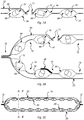
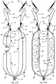
- Figures 2A to 2C illustrate, sections of a flexible panel and bag not according to the invention with cavities for sorbent material.
- the example described with reference to Figures 2A to 2C may be used in combination with any of the features described with reference to Figure 1 .
- FIGS 2A to 2C illustrate the following features:
- a section of flexible panel is shown for use in a sealable bag having inner and outer layers, the flexible panel has two permeable inner layers 34 and an impermeable outer layer 33 affixed together so as to provide a plurality of cavities 69 for receiving sorbent material 70.
- the cavities 69 are arranged in a pattern across the flexible panel. In this case the pattern is an array of constant pitch, however any pattern arrangement that spreads the cavities, and therefore sorbent materials, across the flexible panel (and therefore inner side of the bag) would be suitable.
- a port 71 is shown extending through all of the layers of the flexible panel. The port 71 is used for introducing into and removing gas and/or liquid from the bag.
- the port 71 may correspond to the external inlet valve 21, outlet valve 22 or vacuum pull valve 23 described with reference to Figure 1 .
- the flexible panel may have one or more electronic components operable to monitor or control a chemical environment in the bag.
- a sensor 36 is provided printed onto the internal layer 34 of the flexible panel.
- a conductor a heater, a processor, a communications transmitter, a communications receiver and a GPS receiver.
- One or more permeable inner layer may be semi-permeable. This allows the material to influence the chemical environment in the bag by only allowing certain molecules or ions to pass through it by diffusion.
- the sorbent material 70 may comprise moisture absorbing and/or oxygen absorbing materials. This influences the chemical environment inside the bag by reducing both the moisture levels and oxygen levels in the bag. This is useful for protecting electronic equipment.
- the sorbent material 70 may comprise odour adsorbing materials. This influences the chemical environment inside the bag by reducing odours, so aiding the recovery of the electronic equipment to an acceptable state for reuse.
- sorbent materials 70 are shown as cylindrical pellets, they could be any shape that fits in a corresponding cavity 69.
- the innermost permeable inner layer 34 is configured to provide a plurality of channels 73.
- a pair of permeable inner layers 34 are affixed together so as to provide the plurality of channels 73 in the inner layer 34 commensurate with the pattern of cavities.
- Channels 73 defined by the inner layer provide an advantageous distributed flow of liquid and gas inside the bag, both to and from inlets and outlets and in to contact with material in the cavities.
- the channels need not be defined by the cavities, however it is convenient to have just one fabrication or patterning step, such as heat sealing, define both the cavities and channels at the same time.
- the permeability of the outermost of the inner permeable layers 33 allows the sorbent to reduce condensation on the inside of the outer permeable layer 34.
- flexible panels may contain moisture absorber (desiccant) and/or oxygen absorber materials (50 in Figure 7 ).
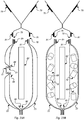
- Figure 3A and 3B illustrate, in schematic form, cross sections of the bag shown in Figure 2C along dotted lines AA and AB respectively.
- Features shown in Figures 3A and 3B that are labelled with the same reference numerals correspond to the identical features illustrated in Figures 2A to 2C .
- chemical agents tied in to the specially made ridges of the layer material 33 and 34 (47 in Figure 7 ) capable of absorbing oxygen (for example iron powder) and capable of absorbing moisture (for example silica gel) as well as retarding biological activity, in addition to functions carried by this layer material with its channelled pathways.
- oxygen for example iron powder
- moisture for example silica gel
- Water damaged items can be placed in the bag device, to absorb water using the highly absorbent material. This material absorbs and locks in moisture many times greater than its own size.
- the system allows for the option of integrated fire odour adsorber technology by means of and not limited to activated carbon inserts.
- the gas film layer, deposited on the equipment components in the bag, after a prolonged time may become less effective. Thus the problem; usually at this point the device would become less effective.
- a feature of this device allows for the electronics components of the device to take over keeping the device active, protecting the item for several months at a time.
- This approach allows for the chemical or electrochemical or biological or thermal or combinations of the aforementioned surrounding conditions within the enclosure to be changed and adjusted for optimal protection of the item placed inside the device. This may be done, for example by the controller activating the heater, actuating electromechanical outlet valves (not shown), or sending an alert to trigger action by a technician.
- Examples described herein provide an internal electronic controller with internal sensors optionally embedded in the bag multilayer flexible panel, alternatively with external connectors to an external controller.
- interconnected layers provide the option for sensor technology 35.
- interconnected layers may including real-time monitoring and computing technology 38.
- Examples of the bag may include a colorimetric sensor, which may provide accurate measurement of oxygen transition rates within this type of bag enclosure.
- This approach can measure a range of pre-set conditions. Versions of the bag can function in real time, through microprocessors, sensor embedded films ( Figure 4 ) and remote monitoring and software programs which can process the pre-set conditions of the environment within the device, allowing for critical optimal preferred levels to be maintained. Real-time alert notifications can be sent to the user, giving warnings of unwanted environmental conditions encountered within the device in addition to location tracking, movement and tampering of the device. This location and GPS tracking feature can be used as standalone device for transportation purposes.
- This approach allows for manual intervention, or for the more elaborate versions to offer remote intervention where manual intervention to monitor or adjust the conditions within the enclosure is not feasible, practical or desired.
- This remote activation and assistance feature allows for remote monitoring and or adjustment of the surrounding conditions inside the device.
- the approach has the optional functionality to change the environment within the enclosure, actively protecting the item for months at a time.
- Examples described herein provide a multi-layer bag with spacers (tie rods, Figure 6 ) between layers to allow gas/moisture flow but that are collapsible when the full vacuum is applied.
- the tie rods 46 supports lifts between the layers and prevents sticking, allows for lifting of the individual layers, helps function more effectively helping in better distribution of gas and nitrogen being pumped in, allows for the inside environmental adjustment without opening the enclosure.
- Nano tie rods may be fitted between the sheets, to prevent moisture and gas vapour pockets traps.
- the tie rods allow for lifting between sheets to allow for air movement.
- Examples described herein provide tubes in the channels functioning to wick moisture by capillary action.
- Examples described herein provide ridges/channels in the inner surface of the bag with channels functioning to facilitate gas/moisture flow.
- This approach helps to address the negative effects encountered by compression blockage narrowing or blockage of the channels caused by vacuum pull and surface contact of the device.
- the width depth and gauge of the channels and ridges allow for water molecules and gases to be directed to another channel should one channel become blocked.
- This approach allows the H 2 0 molecules to leave the material to be dried and gives the H 2 0 molecules a path to the drying agent 48. Furthermore, this approach allows molecules to diffuse into the reactive drying agent.
- this design feature allows for the moisture to make contact with the chemical agent. This action allows for the moisture to be arrested locking the moisture in to the material chambers. This helps to reduce the quantity of free water molecules within in the device in turn reducing oxidation and biological activity.
- Examples described herein provide ridges functioning as impact barriers.
- the ridges 49 are designed and constructed to give a cushion affect acting as impact barriers, helping to absorb shocks from knocks and bangs thus reducing the impact on the equipment placed inside the device, during for instance, transporting.
- the ridges 49 correspond to the cavities shown in Figures 2A to 3B , as well as the cavities shown in Figures 16 to 20B .
- tubing shaped like drinking straws, vertically configured on the pathways along the ridges 48 giving function to capillary movement through cohesion and adhesion.
- the tiny tube-shaped inserts When water comes in contact with the tubing, the tiny tube-shaped inserts allows the water to be pulled away, drawn through the tubing towards the positioned outlet valve. This helps to reduce the reaction between the water and the metallic surface (oxidisation). This configuration also helps to combat the chemical reactions particularly that which takes place when HCL meets H 2 0 molecules in the confines of a closed space, intensifying the likelihood for corrosion and giving rise to the problem of sweating inside the enclosure.
- Another design feature makes use of gravity, vacuum pressure, temperature, and vapour pressure to assist with the desired movement of water vapour and other fluids (gases or liquids) within the enclosure.
- the device uses both condensation and evaporation process to its advantage in recovering greater amounts of contaminants than otherwise without.
- the channels 73 may be interconnected.
- the interconnection of the channels 73 provides a further distributed flow of liquid and gas inside the bag and in to contact with further material in the cavities.
- At least some of the channels may be configured to radiate from an outlet of the bag.
- the channels radiating from an outlet of the bag provides channelled flow of liquid and gas inside the bag towards the outlet. This feature allows for the release of trapped air, and allows for moisture movement to happen in order for the extraction to be more effective.
- Examples described herein provide membrane layer with different sized pores 53 functioning to separate and entrap different gases/liquids.
- the layers may have a selectively permeable membrane, differentially permeable membrane configuration assembled to order at the manufacture stage.
- Vacuum sealable material is integrated into the multi-layer design, which consists of individual layers of specific material, including ESD material, membrane molecular sieves, chemical delivery membrane and multipurpose raised ridged layer acting as an impact absorber and a path to the drying agent.
- the multi-layer feature allows for oxygen, moisture, gases, odour molecules and volatile organic molecules to channel through the correct paths using respective critical diameter pores embedded within each specific layer.
- the molecular sieve design of the optional multi-layer material allows for each gas and liquid to be selectively trapped on to the preferred layer, for removal or absorption or decontamination.
- the active individual layer arrangement favours an efficient performance of the load distribution on each membrane configuration.
- Examples described herein provide internal heating means, optionally as heating layer ( Figure 10 , 58, 60), optionally with external electrical connections.
- the bag may allow for vaporisation of sitting water. This is aided by the optional heating element 60.
- a spherical ball-shaped tablet of moisture absorber (desiccant) and oxygen absorber materials and optional heating chemicals is shown. It for use in a bag. It is activated by breaking a seal (e.g. peeling).
- This ball or tablet can be provided on its own or as a consumable for use with any sealable bag.
- the tablet is not limited to being spherical in shape, for example it may be a cylinder, cube cuboid, cone, hexagonal prism, ellipsoid, cone, prism or pyramid.
- This tablet can work with the active ingredients being chemical agent, moisture absorber and heat activator, kept in individual compartments or layers of the tablet readymade in to the ball of Figure 11 which is activated by peeling of the packaging 66 and placing directly in to the bag.
- active ingredients being chemical agent, moisture absorber and heat activator
- the ball option containing the active ingredients 62 allows for the chemical agents to work more effectively, the ball option is useful when using custom build option to encase large electronic equipment, machinery, etcetera.
- the ball may be used with a plain bag (having no sorbents). For example in the event of a flood warning a television or sofa for example could be placed in a large bag. After breaking the seal on the ball by tearing off the peelable layer and putting the ball into the bag.
- the ball may further contain a structure, such as a cage or a mesh, to contain the materials of the ball and separate them from the contents of the bag, while allowing the oxygen and moisture absorbers to function.
- Figure 12 illustrates the following feature: 67: Shows the tongue side of the (tongue and groove) heat sealable layer, which aids custom builds and seal tightness.
- custom builds flexible panels provided in sheets or on a roll may be cut to size and assembled into larger structures using the heat sealing and/or tongue and groove to attach panels together.
- Figure 13 illustrates the following feature: 68: Shows the groove side of the (tongue and groove) heat sealable layer, which aids custom builds and seal tightness.
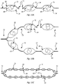
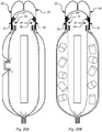
- Figures 14A to 14C illustrate, in schematic form, sections of a flexible panel and bag with cavities for sorbent material defined by non-continuous permeable layers 34.
- the inner layers 34 defining the cavities may be affixed to the outer layer using adhesive.
- the pairs of permeable inner layers 34 have gaps 74 between them in the plane of the flexible panel so as to provide a similar effect as the plurality of channels 73 illustrated in Figures 2A to 2C . Similar to the channels 73 discussed with reference to Figures 2A to 2C , the gaps 74 in this example defined by the edges of the inner layers provide an advantageous distributed flow of liquid and gas inside the bag, both to and from inlets and outlets and in to contact with material in the cavities.
- Figures 15A to 15C illustrate, in schematic form, sections of a flexible panel and bag with cavities for sorbent material defined by a single permeable layer.
- the inner layer is affixed to the outer layer by conventional heat sealing.
- the impermeable outer layer 33 and a permeable inner layer 34 are affixed together so as to provide a plurality of channels 73 in the inner layer 34 commensurate with the pattern of cavities.
- Channels 73 defined by the inner layer provide an advantageous distributed flow of liquid and gas inside the bag, both to and from inlets and outlets and in to contact with material in the cavities.
- the outer layer also has channels, but it is the channels 73 defined by the inner layer that provide an advantageous distributed flow of liquid and gas inside the bag, both to and from inlets and outlets and in to contact with material in the cavities.
- a permeable inner layer with cavities arranged in a pattern across the flexible panel allows the sorbent and optional biologically retardant material to influence the chemical environment in the bag by allowing liquids or gases to pass through the inner layer, while keeping the sorbent (such as the moisture absorbing and/or oxygen absorbing materials) separated from the contents of the bag and at the same time distributed across the flexible panel, so covering a large area of the items (such as electrical equipment) in the bag.
- the sorbent such as the moisture absorbing and/or oxygen absorbing materials
- the flexible panels of the bag can be manufactured with the optimum amount of sorbent per unit area.
- the flexible panels may be conveniently manufactured and shipped as a long roll that can be cut to the desired length of panels by the end user, for assembly into bags of the optimum size.
- the mouth of the bag may be sealed by heat sealing the lips of the mouth defined by the flexible panel.
- the mouth of the bag may be sealed by attachment to a floor, using tape for example. If a such a bag is made of several flexible panels attached together, it is in effect a tent that will protect and preserve its contents. This is useful for large and heavy equipment that cannot be easily lifted into a bag.
- the size of the cavities defined by the affixing pattern can serve to measure out the sorbent with the user simply filling up the cavities in turn to give a total amount proportional to the inner surface of the bag.
- the cavities can be preloaded during manufacture with sorbent, thus reducing the number of components in the system for the end user. Thus, the user does not have the inconvenience of carrying separate packets of absorber material.
- Preloading the cavities during manufacture can secure the sorbent materials so that they don't fall out of the bag.
- nitrogen or a specially formulated pacifying gas may be pumped in through the inlet valve 21 by means of a thermo fogger.
- a problem is that when pumping the pacifying medium into the bag to coat the surface of the equipment therein, the pacifying medium can interact with the sorbent and/or biologically retardant material. This can make the surface coating delivered by the pacifying medium less effective. It can also contaminate the sorbent and/or biologically retardant material, making it less effective in protecting the equipment from corrosion.
- FIGS 16 to 20 disclose an embodiment that addresses this problem.
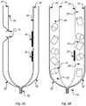
- Figure 16 illustrates, in schematic form, a bag having a manually rupturable impermeable inner layer.
- the bag may have a flexible panel with cavities for sorbent material in accordance with the example described with reference to any of Figures 2A to 3B , 14A to 14C , 15A to 15C , alone or in combination.
- the manually rupturable impermeable inner layer described with reference to Figured 16 to 20C may be used with flexible panels having no cavities for sorbent material.
- the sorbent materials may be in loose sachets in the bag or provided as layers laminated in the flexible panel or as separate sheets.
- the manually rupturable impermeable inner still serves to separate the sorbent from the item in the bag while the pacifying gas is being used.
- the bag 75 is shown in plan view with an outer layer 33.
- the dotted lines show the edges of curved features visible in plan view, thus indicating the topology of the bag.
- Figures 17A to 17B show the same bag in cross section along lines CC and DD respectively.
- the flexible panel 76 has at least one permeable inner layer and an impermeable outer layer 33 affixed together so as to provide a plurality of cavities for receiving sorbent material, the cavities being arranged in a pattern across the flexible panel. In this view, only the impermeable outer layer 33 of the flexible panel is visible.
- the heat sealed edges 72 of the bag are shown.
- the external inlet valve 21 and outlet valve 22 are shown.
- affixed can mean directly affixed, for example in contact, and indirectly affixed, for example indirectly via another layer or via an intermediate adhesive layer.
- An impermeable inner layer 77 can be seen protruding from an aperture 78 in the impermeable outer layer 33.
- the impermeable outer layer 33 is provided with a second adhesive seal 79, covered by a peelable protective layer 80.
- Figures 17A and 17B illustrate, in schematic form, cross sections of the empty bag shown in Figure 16 , having a manually rupturable impermeable inner layer 77 adhered to first adhesive seals 81 to seal an aperture.
- the impermeable inner layer 77 is affixed to the impermeable outer layer 33 at the heat sealed edge of the bag 72 and disposed on the opposite side of the pair of permeable inner layers 34 from the impermeable outer layer 33.
- the impermeable inner layer 77 is configured to separate the cavities 69 from contents of the sealable bag.
- the inner layer 77 is affixed indirectly by the heat seal 72 to the outer layer 33 via the sandwiched inner layers 34.
- the impermeable outer layer 33 is provided with at least one first adhesive seal 81 around the aperture 78.
- the impermeable inner layers 77 are removably adhered to the first adhesive seals 81 to seal the aperture 78 of the impermeable outer layer 33.
- the extremities of the aperture 78 may not be completely sealed by the first adhesive seal with the impermeable inner layer adhered to it.
- external adhesive patches may be applied to the extremities of the aperture to enhance the sealing.
- the impermeable outer layer 33 comprises an aperture 78 for manual rupturing of the impermeable inner layer 77 in use to expose the cavities 69 (and the sorbents 70 contained therein) to the contents of the sealable bag.
- Figures 18A and 18B illustrate, in schematic form, cross sections of the bag shown in Figures 17A and 17B , having had an item 82 inserted, and having been sealed at the mouth of the bag 83.
- FIGs 18A and 18B that are not labelled with reference numerals correspond to the identical features illustrated in Figures 17A and 17B .
- the mouth of the bag 83 may be sealed by heat sealing 84 of the impermeable outer layers 33 that define the mouth of the bag.
- Pacifying gas is illustrated being pumped in as a large arrow 85.
- FIGs 18A and 18B that are not labelled with reference numerals correspond to the identical features illustrated in Figures 17A and 17B .
- Figures 19A and 19B illustrate, in schematic form, cross sections of the sealed bag shown in Figures 18A and 18B , after removal of the manually rupturable impermeable inner layer 77 by pulling it out of the bag through the aperture 78.
- FIGs 19A and 19B that are not labelled with reference numerals correspond to the identical features illustrated in Figures 17A and 17B .
- the remnants 86 of the impermeable inner layer 77 are shown.
- the impermeable inner layer 77 is thus manually rupturable in use to expose the cavities 69 to the contents 82 of the sealable bag.
- the impermeable inner layer 77 is manually detachable in use from the impermeable outer layer 33 to expose sorbent materials 70 in the cavities 69 to the contents 82 of the sealable bag.
- to be detachable means that the impermeable inner layer becomes substantially unattached to the impermeable outer layer.
- a relatively small remnant of the impermeable inner layer remains affixed to the impermeable outer layer, when the impermeable inner layer is detached.
- Other ways of manually rupturing the impermeable inner layer 77 may include tearing by distorting the bag or pulling a string through a small aperture in the impermeable outer layer 33 so as to tear the impermeable inner layer 77.
- the impermeable outer layer 33 is provided with a second adhesive seal 79.
- the second adhesive seal 79 is configurable to seal the aperture 78 of the impermeable outer layer 33 after removal of the impermeable inner layer 77 from the at least one first adhesive seal 81.
- the protective strip shown in Figures 16 to 17B has been removed prior to the next step shown in Figures 20A and 20B .
- Figures 20A and 20B illustrate, in schematic form, cross sections of the sealed bag shown in Figures 19A and 19B , after sealing the aperture of the impermeable outer layer using a second adhesive seal.
- FIGs 20A and 20B that are not labelled with reference numerals correspond to the identical features illustrated in Figures 17A and 17B .
- the top of the impermeable outer layer 33 has been folded over to bring the second adhesive seal 79 in place to cover the aperture 78.
- the second adhesive seal 79 seals the aperture by adhering to a part of the first adhesive seal 81 and the other surface of the outer impermeable layer 33.
- the method comprises the steps of:
- the step of manually rupturing the impermeable inner layer may involve manually detaching the impermeable inner layer from the impermeable outer layer to expose the cavities to the item in the sealed bag.
- the aperture 78 is provided in the impermeable outer layer, and the step of manually rupturing the impermeable inner layer uses the aperture.
- the method may further comprising the steps of:
- the method further comprises the steps of:
Landscapes
- Engineering & Computer Science (AREA)
- Chemical & Material Sciences (AREA)
- General Chemical & Material Sciences (AREA)
- Oil, Petroleum & Natural Gas (AREA)
- Mechanical Engineering (AREA)
- General Engineering & Computer Science (AREA)
- Life Sciences & Earth Sciences (AREA)
- Analytical Chemistry (AREA)
- Health & Medical Sciences (AREA)
- Molecular Biology (AREA)
- Chemical Kinetics & Catalysis (AREA)
- Packages (AREA)
- Respiratory Apparatuses And Protective Means (AREA)
- Air Bags (AREA)
- External Artificial Organs (AREA)
- Sampling And Sample Adjustment (AREA)
Description
- The present invention relates to a sealable bag for use with sorbent material, such as oxygen and moisture absorbers and odour adsorbers. The present invention also relates to a method of preserving an item. Such a bag and method are known from
JP10250774A - Following a fire or a flood, humidity levels can rapidly rise and corrosive environments can manifest. If metallic surfaces and sensitive electronic equipment are left exposed in this environment, they can become prone to corrosion.
- Immediately following a fire or flood, there is an opportunity for restoration of electronic equipment. Such restoration can be highly effective, however this option has time constraints; the restoration must be done quickly. As this time-restricted window of opportunity subsides, the opportunity for economic restoration becomes less likely. As each hour passes the extent of the damage increases. A damage assessment of fire or flood damaged equipment inspected on day one of the incident may indicate that the equipment is salvageable. However, this may no longer be the case on day two. This is a huge problem for all concerned.
- Dehumidifiers can be used to reduce moisture levels from whole rooms or buildings, but only water and/or water vapour is removed and the timescale is too long to prevent irrecoverable damage to electronic equipment. Furthermore, in a major flood incident, there can be a scarcity of dehumidifying plant across the whole region affected. Also dehumidifiers and in particular desiccant dehumidifiers can cause Electrostatic Discharge (ESD) problems.
- With finite resources given to the restoration effort, even prioritising which equipment to start with takes up valuable time.
- Problems exist when using drying agents including sodium, potassium and magnesium in a confined enclosure, on contact with various organic substances. Furthermore, fire or flood damaged equipment poses a hazard which can exacerbate the risks. Unlike uncontaminated equipment, fire and flood damaged items have to be treated with caution as a chemically or biologically active film may exist on the surface of the equipment.
- A known approach to providing a controlled local environment to halt the degradation of electronic equipment that has been subjected to fire or flood is to use a sealable bag.
- UK patent
GB2350347 - A problem with this is that the oxygen absorber is not separated from the electrical equipment in the bag, so it can become damaged and can itself contaminate the electrical equipment.
- US patent application
US5739463 in the name of Raychem Corporation discloses sealed electronics packaging for the environmental protection of active electronic circuit boards and the like assemblies. An envelope has walls of a laminate material. The particular sheet material comprises top and bottom layers of a suitable material such as low density polyethylene about 200 microns thick and two interior layers about 80 microns thick of cast polyamide or polyester and a central layer of about 20 microns thick of aluminium or other suitable material. A problem of sharp points extending from the active electronics and puncturing the sheet material was addressed by surrounding the active electronics with an extruded plastic mesh tube with large holes, plastic foam, fish paper, or paper containing desiccant materials. After an electrical connector is engaged a packet of desiccant/scavenger is inserted into the open end of the packaging and the back edge is sealed using a simple heat sealing machine. - Japanese patent application
JP2009040440A - A problem with this is that the laminate is relatively expensive to manufacture. Furthermore, it does not provide oxygen absorbing and moisture absorbing materials on the same wall of the bag. Therefore the oxygen and moisture absorbing functions do not fully surround the electronic equipment.
- Another approach is using packets of desiccant/scavenger. The packets are localised in one part of the bag. Therefore the oxygen and moisture absorbing functions do not fully surround the electronic equipment. Furthermore, packets of desiccant/scavenger can slip to the bottom of the bag, ending up in a pool of water, thus saturating them.
- Another problem is that if the bags have different sizes, the then the user would have to calculate or follow instructions to determine how many packets or what size of packet should be added in order to put in the correct amount of absorbing material.
- When using packets of desiccant/scavenger added at the time of use, the user has to keep a separate supply of packets of desiccant/scavenger.
- If the bags are loaded with packets during manufacture, then they could fall out.
- It is an object of aspects of the present invention to overcome at least some of the problems identified above.
- According to a first aspect of the present invention there is provided a sealable bag in accordance with
claim 1. Claims 2-10 concern preferred embodiments. - Preferably, the impermeable outer layer comprises an aperture for manual rupturing of the impermeable inner layer in use to expose the cavities to the contents of the sealable bag.
- Preferably, the impermeable outer layer is provided with at least one first adhesive seal around the aperture and the impermeable inner layer is removably adhered to the at least one first adhesive seal to seal the aperture of the impermeable outer layer.
- Preferably, the impermeable outer layer is provided with a second adhesive seal configurable to seal the aperture of the impermeable outer layer after removal of the impermeable inner layer from the at least one first adhesive seal.
- Preferably, the flexible panel further comprises sorbent material contained in a plurality of the cavities.
- Preferably, the sorbent material comprises at least one sorbent selected from the group: moisture absorbing material, oxygen absorbing material and odour adsorbing material.
- Preferably, the flexible panel further comprises biological activity retardant material contained in a plurality of the cavities.
- Preferably, at least one permeable inner layer is configured to provide a plurality of channels.
- Preferably, at least some of the channels are interconnected.
- Preferably, at least some of the channels are configured to radiate from a port in the outer impermeable layer.
- Preferably, the flexible panel further comprises tubes arranged in the channels configured to wick moisture along the channels by capillary action.
- Preferably, the flexible panel further comprises tie rods between a pair of layers in the flexible panel, the tie rods configured to be collapsible in use responsive to a pressure difference across the layers of the flexible panel.
- Preferably, the flexible panel comprises a plurality of permeable layers with differing pore sizes configured to separate different gasses and or liquids into different respective cavities bounded by the permeable layers with differing pore sizes.
- Preferably, the flexible panel flexible further comprises one or more electronic components operable to monitor or control a chemical environment in a bag.
- Preferably, the components are printed onto a layer of the flexible panel.
- Preferably, the components comprise one or more components selected from the group: a sensor, a conductor, a heater, a processor, a communications transmitter, a communications receiver and a GPS receiver.
- Preferably, the flexible panel further comprises a flow-regulating outlet port through the outer impermeable layer.
- Preferably, the flexible panel further comprises an antistatic port through the outer impermeable layer.
- Preferably, the flexible panel further comprises a condensation release valve in fluid communication with a port through the outer impermeable layer.
- Preferably, the flexible panel further comprises a thermoplastic tongue member or a thermoplastic groove member of a heat sealable tongue and groove closure.
- According to a second aspect of the present invention, there is provided a method of preserving an item in accordance with
claim 11. Claims 12-15 concern preferred embodiments of the method. - Preferably, the step of manually rupturing the impermeable inner layer comprises manually detaching the impermeable inner layer from the impermeable outer layer to expose the cavities to the item in the sealed bag.
- Preferably, the method of preserving an item further comprises the step of providing an aperture in the impermeable outer layer, and wherein the step of manually rupturing the impermeable inner layer uses the aperture.
- Preferably, the method of preserving an item further comprises the steps of:
- providing the impermeable outer layer with at least one first adhesive seal around the aperture;
- removably adhering the impermeable inner layer to the at least one first adhesive seal to seal the aperture of the impermeable outer layer; and
- manually rupturing the impermeable inner layer by manually detaching the impermeable inner layer from the first adhesive seal and pulling the impermeable inner layer out of the bag through the aperture.
- Preferably, the method of preserving an item further comprises the steps of:
- providing the impermeable outer layer with a second adhesive seal; and
- sealing the aperture of the impermeable outer layer using the second adhesive seal after pulling the impermeable inner layer out of the bag through the aperture.
- Embodiments of the present invention will now be described by way of example only with reference to the following drawings:
-
Figure 1 illustrates, in schematic form, a bag having various features in accordance with embodiments of the present invention. -
Figures 2A to 2C illustrate, in schematic form, sections of a flexible panel and bag with cavities for sorbent material not in accordance with an embodiment of the present invention. -
Figure 3A and 3B illustrate, in schematic form, cross sections of the bag shown inFigure 2C . -
Figure 4 illustrates, in schematic form, a bag having sensors and control components. -
Figure 5 illustrates, in schematic form, a bag for use with an external controller module. -
Figure 6 illustrates, in schematic form, a cross section of layers of a bag connected by tie rods. -
Figure 7 illustrates, in schematic form, a bag with cavities and interconnected channels. -
Figure 8 illustrates, in schematic form, a bag with critical diameter. -
Figure 9 illustrates, in schematic form, a bag with a catchment reservoir. -
Figure 10 illustrates, in schematic form, a bag with an externally powered heating element. -
Figure 11 illustrates, in schematic form, a sealed tablet having active ingredients. -
Figures 12 and 13 illustrate, in schematic form, a bag having tongue and groove heat sealable layers. -
Figures 14A to 14C illustrate, in schematic form, sections of a flexible panel and bag with cavities for sorbent material defined by non-continuous permeable layers. -
Figures 15A to 15C illustrate, in schematic form, sections of a flexible panel and bag with cavities for sorbent material defined by a single permeable layer not in accordance with an embodiment of the present invention. -
Figure 16 illustrates, in schematic form, a plan view of a bag having a manually rupturable impermeable inner layer in accordance with an embodiment of the present invention. -
Figures 17A and 17B illustrate, in schematic form, cross sections of the empty bag shown inFigure 16 , having a manually rupturable impermeable inner layer adhered to first adhesive seals to seal an aperture, in accordance with an embodiment of the present invention. -
Figures 18A and 18B illustrate, in schematic form, cross sections of the bag shown inFigures 17A and 17B , having been sealed with an item inserted, and pacifying gas being pumped in. -
Figures 19A and 19B illustrate, in schematic form, cross sections of the sealed bag shown inFigures 18A and 18B , after removal of the manually rupturable impermeable inner layer by pulling it out of the bag through the aperture. -
Figures 20A and 20B illustrate, in schematic form, cross sections of the sealed bag shown inFigures 19A and 19B , after sealing the aperture of the impermeable outer layer using a second adhesive seal. - Examples described herein takes in to consideration the mixed chemical reaction that can take place, subsequently enhancing chemical actions and reactions to get the desired effect in addition to allowing for exhaust, collection and control of unwanted by products, through an active working enclosure comprising flexible panels.
- Drying agents tend to clump during the water absorption process, disintegrate or form a syrupy layer. The approach described herein tackles this problem by containing sorbents in cavities.
- Examples described herein provide chemical delivery and contamination recovery carried out in an encapsulated device with the integrated option of sensor and microprocessor technology.
- Examples described herein relate to a multifunction device that actively prevents the onset of corrosion, retards biological activity, recovers excess moisture, neutralizes acidic residue, and combats oxidizing chemical agents which are not limited to members of the chalcogen group on the periodic table. This approach is applied to, but not limited to, electronic equipment following and not limited to incidents such as fires or pre and post disaster flooding.
- This bag device having flexible panels works in low moisture environments and high moisture environments.
- Examples described herein have the optional functionality allowing for selective interchangeable layer option to be used based on individual requirements.
- This allows for the option to use single or multi- layer configuration of the optional layers in combination or singly, using nano films, membrane configuration units, nano printed sensor films, oxygen and moisture retarding materials embedded into the film, ESD film, heating film, impact absorber sheet, external electronics controller module, monitoring sensors embedded material, custom build interlocking layers, multifunction sensor embedded material, gas removal filtration system, constant vacuum pull system, IP67 protection compliant sealing outer material, specially designed vacuum pull and channelled moisture and gas path ways, allowing for simultaneous recovery and processing of more than one contamination stream.
- The ports and components can be configured and can be interchanged at manufacturing stage. Sensors can also be placed on to alternative layers at manufacturing stage.
- Examples described herein help to solve the problem of occupational exposure (secondary contamination) of restoration and insurance personal, from exposure to off gassing of smoke damaged items. Such bag devices retard corrosion without destroying the items placed inside the device.
- Examples described herein help to solve the problem of occupational exposure of restoration and insurance personal from water damaged items. Such bag devices retard biological activity without destroying the items placed inside the device.
- More elaborate examples of the bag may carry out real-time management with constant monitoring through smart sensors, printed directly onto a flexible layer surface using organic and printed electronics technology and communication systems.
- Unlike a vacuum bag, examples described herein provide an active working enclosure, which can be adjusted to change the environment, limiting gaseous by-products, exchanging air, and removing condensation.
- Acronyms used in the description are defined below:
- ESD: Electrostatic discharge.
- H20: The molecular formula for water.
- Lipo: Lithium Polymer battery a type of rechargeable battery.
- GPS: Global positioning system.
- IP67: Ingress Protection from dust and protected against immersion.
- PCB: printed circuit board.
- EEPROM: read/write internal memory of an MCU.
- Fogger: A device that spreads a chemical in the form of fog.
- HCL: Hydrochloric acid.
-
Figure 1 illustrates the following features: - 1: Multifunction - Electronics pre and post disaster recovery device, comprising a bag having one or more flexible panels as its walls.
- 2: Contaminated item to be protected, placed inside the device.
- 3: Manual moisture indicator card pouch.
- 4: Manual moisture indicator card.
- 5: Manual moisture indicator card pull out activator tab.
- 6: Manual moisture indicator card self-seal flap over airtight seal.
- 7: Multi-layer sandwich configuration with one layer use or multi-layer use option can be deployed.
- 8: Multi-layer sandwich configuration with one layer used or multi-layer use option can be deployed.
- 9: Multi-layer sandwich configuration with one layer used or multi-layer use option can be deployed.
- 10: Multi-layer sandwich configuration with one layer used or multi-layer use option can be deployed.
- 11: Multi-layer sandwich configuration with one layer used or multi-layer use option can be deployed.
- 12: Thermal seal lip on the open end of the enclosure for heat sealing airtight.
- 13: Zip lock seal on the open end of the enclosure for slide zip closure option.
- 14: Strip and rod insert type seal on the open end of the enclosure.
- 15: Particulate filter for filtration and outlet exhaust of gases produced within the enclosure.
- 16: Particulate filter open and close valve.
- 17: ESD internal enclosure feature (connects to the equipment placed inside the enclosure).
- 18: ESD external 10mm male stud (for connection to ESD grounding plug).
- 19: ESD internal flex connecting lead.
- 20: ESD internal connecter (connects to the item placed inside).
- 21: Fully sealed antistatic inlet valve, allows for gas to be pumped in externally to the closed enclosure.
- 22: Fully sealed antistatic regulated outlet valve, allows for the gas within the enclosure to be removed under control after the penetration time is complete. Also allows for the air to be removed aiding in the air tight enclosure.
- 23: 360° vacuum pull valve, allows for the inner enclosure to be vacuumed.
- 24, 25, 26 and 27: Vacuum sealable sides - aids interlocking feature, custom builds and 1P67 protection.
- 28: Ionize air gun port, allows for an ionize gun to be connected from external port to help dissipate static charges.
- 29: Optional wireless feature.
- 30: Optional condensation release valve.
- 31: Electronics connecter.
- 32: Vacuum pull lines, spread across the layers to help 360° vacuum pull, which is exctracting gas from all radial directions in the bag towards the outlet port.
- 55: Optional manual heat activator pouch.
- 56: Optional manual heat activator packet.
- Electronic equipment may be rescued through this active working enclosure resulting in protection from further contamination and degradation of the equipment, due to the threat or possibility of corrosive contamination penetrating the equipment.
- Examples described herein prevent cross contamination by the potentially contaminated items being protected within the enclosure.
- Examples described herein prevent occupational exposure by the potentially contaminated items being protected within the enclosure.
- Examples described herein prevent the spread of viruses, mould spores, asbestos fibres and other hazardous substances/material by the potentially contaminated items being protected within the enclosure
- Examples described herein allow an ingress rating of (IP67) protecting electronics in the enclosure from outside environmental conditions as well as preventing water ingress in to the sealed enclosure.
- ESD material may be integrated into the material of the flexible panel. The flexible panel of the bag wall may have conductive tracks (for example contact strips) affixed to or embedded in it.
- The conductive tracks may be connected to an ESD external 10mm
male stud 18, for connection to ESD grounding strap or for static discharge by a handheld static discharge device. - The conductive tracks may be connected to an internal card (such as the
computer 38 with the entire processor being the size of a SD card) that is additionally provided with an ESD removal chip. - The conductive tracks may be connected via the
electronics connector 31 to an external module (such as the electronics controller module externally mounted outside of the bag) that is additionally provided with an ESD removal chip. - Nitrogen may be used to re-inflate the enclosure and for air exchange benefits.
- This device uses puncture-resistant materials. The flexible panels of the bag may be made of layers of a plastic such as polyethylene (PE). This has the advantage that the layers may be heat sealed together. Thicker gauge polyethylene terephthalate (PET) may also be suitable and may be more puncture-resistant.
- Examples described herein provide ridges or tubes (
Figure 1 , 32) that radiate from the vacuum pull valve (Figure 1 , 23). This allows for 360° vacuum pull. - The air release valve feature, allows for gas to be sucked in along the whole ridged pathways, which travels across the surface. This feature allows for the release of trapped air. This feature also allows for moisture movement to happen in order for the extraction to be more effective.
- Examples described herein provide internal heating means. This approach allows for bags to incorporate thermal functions to encourage vaporisation of sitting water from the item placed inside the enclosure aided by the
optional heat activator 55 by exposing the heat activator to the open bag enclosure. - The sitting water is warmed up by heat generating material or layers. The increase in temperature encourages vaporisation of liquid to gas which is absorbed by the moisture absorbing material more easily. The kinetic energy from the heating provides better mass transport of gas within the bag and can also increase the efficiency of the sorption. The device can be used in conjunction with a specific heat calculator for exact amount of formulation. External heat trays can be placed outside of the device aiding temperature settings. The temperature inside the enclosure is measured by either an infra-red thermometer or sensors, this measurement along with the mass will give an idea of how much formulation needs to be added.
- Examples described herein provide internal GPS/messaging means for remote monitoring, control and notifications. Examples described herein incorporate a GPS tracking feature that is operational in real-time. Examples described herein incorporate a security and tamper feature that is operational in real-time.
- A regulated outlet functional to prevent damage to equipment being protected by too fast air flow (static) or impulse from deflating bag. Inlet and outlet ports are anti-static to reduce static build up in use.
- Relative humidity should be kept within acceptable limits to avoid susceptibility to static charge build up and ESD damage. The desiccant can cause such problems by lowering the relative humidity below 10%. One way to avoid this problem is by using desiccants calibrated and specified to only bring the relative humidity down to a certain level. In terms of reducing damage to the equipment in the bag, a relative humidity of 37% or less is desirable. Therefore it is preferable to provide a relative humidity within the range preferably with a lower limit of 11-12% and a higher limit of 37%. The electronic monitoring and control functions described herein may use this range for control limits. The heating elements described herein may be used for automatic control of relative humidity in the bag.
- With reference to
Figure 1 , nitrogen or a specially formulated pacifying gas is pumped in through theexternal inlet valve 21 for example by means of a thermo fogger. - The pacifying gas may be provided in two formulas. One formula of the pacifying gas is to be used after fires in order to retard the negative effects of the smoke damage on the equipment which is placed inside the enclosure for treatment and protection. The second formula of the pacifying gas is used pre- and post-flooding in order to retard the biological activity and other negative effects on the equipment, which is placed inside the enclosure for treatment and protection.
- The gas particles are able to penetrate beneath components on circuit board without the need for dismantle the equipment being placed inside the enclosure, the gas has good adhesion properties when used inside the enclosure. Furthermore the enclosure helps the gas to create an even coating on the equipment.
- The gas stays in the sealed enclosure for a period of time, such as 5 to 20 minutes. After such time it is sucked out by means of a wet vacuum device through the
outlet valve 22. - Thus, after a period of dwell time, the gas is removed from the enclosure using a chemical filtered wet vac through the regulated outlet valve 22.The flow regulated outlet valve serves several purposes including preventing the electronics components from becoming loosened due to the forces placed on them ordinarily in cases of unregulated air removal.
- As the gas is being removed some of the air is also removed under antistatic conditions provided by the antistatic features described herein.
- Then an antistatic vacuum device capable of handling moisture is connected to the vacuum pull valve 23.The enclosure is then vacuumed, again flow-regulated preventing the electronics components from becoming loosened due to the forces placed on them ordinarily in cases of unregulated vacuum removal.
- The device can be used with liquid friendly vacuum chamber unit convenient for puling liquids without damaging the vacuum device.
- The equipment placed inside the device is now encapsulated in this active working enclosure and is constantly treated by means of, but not limited to, activated ingredients as described herein. Furthermore, another feature of this bag device is its ability to being able to process and exhaust the produced gases and modify the environmental conditions within the internal enclosure without having to open the bag device fully.
- The bag is able to process and or exhaust and or filter the by-products produced as a result of the item placed in the device. In addition the approach allows for the option of air exchange and condensation removal. The air exchange can be done with, but not limited to, nitrogen introduced into the device.
- This approach has embedded fully sealed antistatic inlet port through which anti corrosive agent / gas can be pumped in under ESD control
- This approach has embedded fully sealed antistatic inlet port through which nitrogen can be pumped in under ESD control.
- This approach has embedded fully sealed antistatic in let port through which antimicrobial agent and relevant decontamination agent's dependent on contamination can be pumped in under ESD control.
- This method of pumping in gases allows for the device to be coated and protected without dismantling the equipment /item placed in it.
- Regulated constant vacuum pull can be applied via the
vacuum pull valve 23 with the additional purpose of addressing vacuum leaks. - This vacuum pull
valve 23 allows for a constant vacuum pull to be applied, unlike other vacuum seal type bags, which can only be vacuumed one time, and then it is heat sealed shut. This feature allows for the vacuum to be applied after the heat sealing is done and at any time whilst the equipment is in the device. - Nitrogen or a specially formulated gas is pumped in through the
external inlet valve 21 by means of a thermo fogger. The gas comes in two formulas. - One formula of the gas is to be used after fires in order to retard the negative effects of the smoke damage on the equipment which is placed inside the enclosure for treatment and protection.
- The second formula of the gas is used pre and post flooding in order to retard the biological activity and other negative effects on the equipment, which is placed inside the enclosure for treatment and protection.
- The gas particles are able to penetrate beneath the components on circuit board, without the need for dismantling of the equipment being placed inside the enclosure. The gas has good adhesion properties, when used inside the enclosure. Furthermore the bag enclosure helps the gas to create an even coating on the equipment.
- The gas adheres to the surface decreasing oxygen production and preventing oxygen introduction. The gas will not introduce oxygen to the surface as the bonded surface rejects air penetration reducing degradation of the newly formed protective coating.
- Examples described herein provide a particle filter on the outlet (
Figure 1 , 15) functioning to filter exhaust gases for operator safety. - The
filter 15 is designed for filtration and provides an outlet for exhaust, for gases produced within the enclosure, resulting from induced chemical reactions and by- products. - The
particulate filter 15 for a gas removal system does not let air in. - Examples described herein provide that the gas that is pumped in contains wax functioning to coat the equipment being protected and functions to protect fusing of smoke particles to the outer casing of the equipment.
- The specially formulated gas serves another purpose. Ordinarily, smoke damaged items placed inside a vacuumed bag would cause the outer layer of the bag and the outer casing of the equipment to fuse the acidic smoke to the casing, making it difficult to remove the smoke staining. The specially formulated gas solves this problem.
- In addition to the benefits offered by the gas in terms of preventing fusing of smoke to the equipment casing, the appropriate contact layer of the device material has a wax coating, offering enhanced protection from fusing.
- The wax layered coatings stops fusion and acid attack of the materials being protected. This material draws smoke residues into its layers whilst the wax provides a sponge effect drawing in the highly charged smoke particles particularly important in high protein type smoke residues.
- Examples described herein provide that the gas that is pumped in is bioactive and functions to retard biological activity (e.g. from flooding by seawater).
- Examples described herein provide a condensation release valve (
Figure 1 , 30). - A
condensation control feature 30 may be integrated in to the device. The channels are fitted into the ridges that as mentioned also act as impact barriers, the moisture can be released out of the bag device as and when necessary. - Examples described herein provide a tongue and groove seal that is heat sealable functioning to close the bag (
Figures 1 ,12 and 13 ). - The
bag 1 allows for electronic equipment to be placed inside the device then closed airtight by any of the closing mechanisms: thermal heat sealing 12; zip lock™ seal slide 13; and strip and rod inserttype seal 14. A combination one or more of the three closing mechanisms can be used. - This bag can be heat sealed or glued or strip sealed or zip-locked air tight, or can be used in combination with all three closing mechanisms creating a triple lock system.
- The interlocking design (with sealable thermal lips and slats, tongue and grove) allows for custom builds. Active glue may be used to bond the surface creating an air tight seal.
- Examples described herein provide a moisture indicator card in a pouch for manual revealing after initial gas/liquid flow (
Figure 1 ,3-6 ). - Examples described herein provide an ionised air gun port (
Figure 1 , 28) that allows for an ionised air gun to be connected to dissipate static charge in the bag. - An ionized air gun port is featured in the design allowing for ionized air gun operation.
- Examples described herein provide internal ESD connectors on the inside of the bag to connect to the equipment being protected (
Figure 1 ,17 ). - Examples described herein thus provide another feature, with wire earth node and attachments to combat static build up and static build up produced by air flow across the surfaces. The inside of the bag device allows for a crocodile type clip or screw to connect directly to the item inside. Also attached for external access is an ESD bonding point with a 10mm diameter.
- Examples described herein provide a strip and rod closing mechanism functioning to close the bag (
Figure 1 ,14 ). - The
item 2 is placed inside the device thus becoming encapsulated. Then a specially formulated gas is pumped in to the closed device through theinlet port 21. - The bag may recover hydrogen halides using activated carbon sorbent and using pacifying gas to pacify HCI. It also recovers water vapour, thus essential in preventing the production of acid. Hydrogen halides are colourless gases at room temperature producing fumes in moist air.
- The mouth of the bag may be heat (or otherwise) sealed at the point of manufacture for storage and transport. Then before use the seal may be broken in order to insert the equipment or item to be preserved. Subsequently, the mouth of the bag is resealed.
-
Figures 2A to 2C illustrate, sections of a flexible panel and bag not according to the invention with cavities for sorbent material. The example described with reference toFigures 2A to 2C may be used in combination with any of the features described with reference toFigure 1 . -
Figures 2A to 2C illustrate the following features: - 33: An impermeable outer layer of the bag.
- 34: Permeable inner layers of the bag.
- 69: Cavities arranged in a pattern across the flexible panel.
- 70: Sorbent material contained in the cavities.
- 71: A port through the flexible panel.
- 72: The sealed edges of the bag.
- 73: Channels defined by the innermost permeable layer of the bag.
- In the Figures of panels and bags showing cross sections and described herein, small gaps are left between some features in order to aid understanding of the structures being depicted. For example in
Figure 2B , the heat sealed layers 72 are shown as not being abutting, however they are actually in contact with each other. The same is true for example at the feature labelled 73. - With reference to
Figure 2A a section of flexible panel is shown for use in a sealable bag having inner and outer layers, the flexible panel has two permeableinner layers 34 and an impermeableouter layer 33 affixed together so as to provide a plurality ofcavities 69 for receivingsorbent material 70. Thecavities 69 are arranged in a pattern across the flexible panel. In this case the pattern is an array of constant pitch, however any pattern arrangement that spreads the cavities, and therefore sorbent materials, across the flexible panel (and therefore inner side of the bag) would be suitable. Aport 71 is shown extending through all of the layers of the flexible panel. Theport 71 is used for introducing into and removing gas and/or liquid from the bag. It is shown here open, but can be connected to with a hose or a closed with a cap. Suitable connectors may be used, such as bayonet or a threaded connector. Theport 71 may correspond to theexternal inlet valve 21,outlet valve 22 or vacuum pullvalve 23 described with reference toFigure 1 . - The flexible panel may have one or more electronic components operable to monitor or control a chemical environment in the bag. In this example a
sensor 36 is provided printed onto theinternal layer 34 of the flexible panel. - Other components may be provided by being affixed or printed on internal layers of the bag, such as: a conductor, a heater, a processor, a communications transmitter, a communications receiver and a GPS receiver.
- One or more permeable inner layer may be semi-permeable. This allows the material to influence the chemical environment in the bag by only allowing certain molecules or ions to pass through it by diffusion.
- The
sorbent material 70 may comprise moisture absorbing and/or oxygen absorbing materials. This influences the chemical environment inside the bag by reducing both the moisture levels and oxygen levels in the bag. This is useful for protecting electronic equipment. - The
sorbent material 70 may comprise odour adsorbing materials. This influences the chemical environment inside the bag by reducing odours, so aiding the recovery of the electronic equipment to an acceptable state for reuse. - Although
sorbent materials 70 are shown as cylindrical pellets, they could be any shape that fits in a correspondingcavity 69. - The innermost permeable
inner layer 34 is configured to provide a plurality ofchannels 73. In this example ofFigures 2A to 2C , a pair of permeableinner layers 34 are affixed together so as to provide the plurality ofchannels 73 in theinner layer 34 commensurate with the pattern of cavities.Channels 73 defined by the inner layer provide an advantageous distributed flow of liquid and gas inside the bag, both to and from inlets and outlets and in to contact with material in the cavities. The channels need not be defined by the cavities, however it is convenient to have just one fabrication or patterning step, such as heat sealing, define both the cavities and channels at the same time. - The permeability of the outermost of the inner
permeable layers 33 allows the sorbent to reduce condensation on the inside of the outerpermeable layer 34. - Examples described herein provide that flexible panels may contain moisture absorber (desiccant) and/or oxygen absorber materials (50 in
Figure 7 ). -
Figure 3A and 3B illustrate, in schematic form, cross sections of the bag shown inFigure 2C along dotted lines AA and AB respectively. Features shown inFigures 3A and 3B that are labelled with the same reference numerals correspond to the identical features illustrated inFigures 2A to 2C . - Within the active bag enclosure in its layer lie chemical agents tied in to the specially made ridges of the
layer material 33 and 34 (47 inFigure 7 ) capable of absorbing oxygen (for example iron powder) and capable of absorbing moisture (for example silica gel) as well as retarding biological activity, in addition to functions carried by this layer material with its channelled pathways. The retarding of biological activity aids the recovery of the electronic equipment by protecting the personnel who open the bag from harmful biologically active material. - Water damaged items can be placed in the bag device, to absorb water using the highly absorbent material. This material absorbs and locks in moisture many times greater than its own size.
- The system allows for the option of integrated fire odour adsorber technology by means of and not limited to activated carbon inserts.
-
Figure 4 illustrates the following features: - 35: Sensor embedded layer.
- 36: Various sensors printed on to the film layer.
- 37: Electronics connector port.
- 38: Optional placement of an internal monitoring and/or controller computer.
-
Figure 5 illustrates the following features: - 39: Optionally, the
electronics controller module 39 may be externally mounted outside of the enclosure. - 37: Connector port.
- 40: EEPROM read/write memory.
- 41: Printed circuit board.
- 42: Lithium battery.
- 43: Electronics components.
- The gas film layer, deposited on the equipment components in the bag, after a prolonged time may become less effective. Thus the problem; usually at this point the device would become less effective. However a feature of this device allows for the electronics components of the device to take over keeping the device active, protecting the item for several months at a time.
- This approach allows for the chemical or electrochemical or biological or thermal or combinations of the aforementioned surrounding conditions within the enclosure to be changed and adjusted for optimal protection of the item placed inside the device. This may be done, for example by the controller activating the heater, actuating electromechanical outlet valves (not shown), or sending an alert to trigger action by a technician.
- Examples described herein provide an internal electronic controller with internal sensors optionally embedded in the bag multilayer flexible panel, alternatively with external connectors to an external controller.
- With reference to
Figure 4 , interconnected layers provide the option forsensor technology 35. With reference toFigure 5 , interconnected layers may including real-time monitoring andcomputing technology 38. - Examples of the bag may include a colorimetric sensor, which may provide accurate measurement of oxygen transition rates within this type of bag enclosure.
- This approach can measure a range of pre-set conditions. Versions of the bag can function in real time, through microprocessors, sensor embedded films (
Figure 4 ) and remote monitoring and software programs which can process the pre-set conditions of the environment within the device, allowing for critical optimal preferred levels to be maintained. Real-time alert notifications can be sent to the user, giving warnings of unwanted environmental conditions encountered within the device in addition to location tracking, movement and tampering of the device. This location and GPS tracking feature can be used as standalone device for transportation purposes. - This approach allows for manual intervention, or for the more elaborate versions to offer remote intervention where manual intervention to monitor or adjust the conditions within the enclosure is not feasible, practical or desired. This remote activation and assistance feature allows for remote monitoring and or adjustment of the surrounding conditions inside the device.
- The approach has the optional functionality to change the environment within the enclosure, actively protecting the item for months at a time.
-
Figure 6 illustrates the following features: - 44: Cross section of the tie rod connection setup.
- 45: Cross section of the material layers connected by the tie rods.
- 46: Tie rods.
- Examples described herein provide a multi-layer bag with spacers (tie rods,
Figure 6 ) between layers to allow gas/moisture flow but that are collapsible when the full vacuum is applied. - The
tie rods 46 supports lifts between the layers and prevents sticking, allows for lifting of the individual layers, helps function more effectively helping in better distribution of gas and nitrogen being pumped in, allows for the inside environmental adjustment without opening the enclosure. - Nano tie rods may be fitted between the sheets, to prevent moisture and gas vapour pockets traps. The tie rods allow for lifting between sheets to allow for air movement.
-
Figure 7 illustrates the following features: - 47: Raised ridge complete layer.
- 48: Pathways between the raised ridges corresponding to the cavities between the inner and outer layers support moisture and gas flow and prevent pathway blockages giving alternative routes for the gas and moisture to travel.
- 49: The raised ridges also act as impact barriers and thus are constructed to absorb shock impacts.
- 50: The raised ridges may contain moisture absorbing and oxygen absorbing materials.
- 51: Shows the optional fixed placed close-proximity heat activator.
- Examples described herein provide tubes in the channels functioning to wick moisture by capillary action.
- Examples described herein provide ridges/channels in the inner surface of the bag with channels functioning to facilitate gas/moisture flow.
- This approach helps to address the negative effects encountered by compression blockage narrowing or blockage of the channels caused by vacuum pull and surface contact of the device. The width depth and gauge of the channels and ridges allow for water molecules and gases to be directed to another channel should one channel become blocked.
- This approach allows the H20 molecules to leave the material to be dried and gives the H20 molecules a path to the
drying agent 48. Furthermore, this approach allows molecules to diffuse into the reactive drying agent. - Due to the precisely placed
desiccant material 50, when moisture flows through these pathways, this design feature allows for the moisture to make contact with the chemical agent. This action allows for the moisture to be arrested locking the moisture in to the material chambers. This helps to reduce the quantity of free water molecules within in the device in turn reducing oxidation and biological activity. - Examples described herein provide ridges functioning as impact barriers.
- The
ridges 49 are designed and constructed to give a cushion affect acting as impact barriers, helping to absorb shocks from knocks and bangs thus reducing the impact on the equipment placed inside the device, during for instance, transporting. Theridges 49 correspond to the cavities shown inFigures 2A to 3B , as well as the cavities shown inFigures 16 to 20B . - The features described with reference to
Figures 1 and4 to 13 may, each or in combination, be used in combination with the examples described with reference toFigures 2A to 3C as well as in combination with the examples described with reference toFigures 14A to 20 . - With reference to
Figure 7 , another feature provides for the use of tubing, shaped like drinking straws, vertically configured on the pathways along theridges 48 giving function to capillary movement through cohesion and adhesion. - When water comes in contact with the tubing, the tiny tube-shaped inserts allows the water to be pulled away, drawn through the tubing towards the positioned outlet valve. This helps to reduce the reaction between the water and the metallic surface (oxidisation). This configuration also helps to combat the chemical reactions particularly that which takes place when HCL meets H20 molecules in the confines of a closed space, intensifying the likelihood for corrosion and giving rise to the problem of sweating inside the enclosure.
- Another design feature makes use of gravity, vacuum pressure, temperature, and vapour pressure to assist with the desired movement of water vapour and other fluids (gases or liquids) within the enclosure.
- The device uses both condensation and evaporation process to its advantage in recovering greater amounts of contaminants than otherwise without.
- With reference to
Figure 7 , at least some of thechannels 73 may be interconnected. The interconnection of thechannels 73 provides a further distributed flow of liquid and gas inside the bag and in to contact with further material in the cavities. At least some of the channels may be configured to radiate from an outlet of the bag. The channels radiating from an outlet of the bag provides channelled flow of liquid and gas inside the bag towards the outlet. This feature allows for the release of trapped air, and allows for moisture movement to happen in order for the extraction to be more effective. -
Figure 8 illustrates the following features: - 52: Shows the critical membrane diameter layer which is used.
- 53: Points to critical diameter pores (not to scale).
-
Figure 9 illustrates the following features: - 54: Shows the optional one way entrapment catchment layer.
- 57: Shows the catchment reservoir.
- Examples described herein provide membrane layer with different
sized pores 53 functioning to separate and entrap different gases/liquids. - The layers may have a selectively permeable membrane, differentially permeable membrane configuration assembled to order at the manufacture stage.
- Vacuum sealable material is integrated into the multi-layer design, which consists of individual layers of specific material, including ESD material, membrane molecular sieves, chemical delivery membrane and multipurpose raised ridged layer acting as an impact absorber and a path to the drying agent.
- The multi-layer feature allows for oxygen, moisture, gases, odour molecules and volatile organic molecules to channel through the correct paths using respective critical diameter pores embedded within each specific layer.
- The molecular sieve design of the optional multi-layer material, allows for each gas and liquid to be selectively trapped on to the preferred layer, for removal or absorption or decontamination.
- The active individual layer arrangement, favours an efficient performance of the load distribution on each membrane configuration.
-
Figure 10 illustrates the following features: - 58: Shows the optional fully collapsible heating layer.
- 59: Shows the outer layer.
- 60: Heating element.
- 61: Electronics connector port.
- Examples described herein provide internal heating means, optionally as heating layer (
Figure 10 , 58, 60), optionally with external electrical connections. - The bag may allow for vaporisation of sitting water. This is aided by the
optional heating element 60. -
Figure 11 illustrates the following features: - 62: Readymade active ingredients ball.
- 63: Oxidising agent.
- 64: Heat generator material.
- 65: Moisture absorbing agent.
- 66: Peel of tab protective packaging.
- With reference to
Figure 11 , a spherical ball-shaped tablet of moisture absorber (desiccant) and oxygen absorber materials and optional heating chemicals is shown. It for use in a bag. It is activated by breaking a seal (e.g. peeling). This ball or tablet can be provided on its own or as a consumable for use with any sealable bag. The tablet is not limited to being spherical in shape, for example it may be a cylinder, cube cuboid, cone, hexagonal prism, ellipsoid, cone, prism or pyramid. - This tablet can work with the active ingredients being chemical agent, moisture absorber and heat activator, kept in individual compartments or layers of the tablet readymade in to the ball of
Figure 11 which is activated by peeling of thepackaging 66 and placing directly in to the bag. - The ball option containing the
active ingredients 62 allows for the chemical agents to work more effectively, the ball option is useful when using custom build option to encase large electronic equipment, machinery, etcetera. The ball may be used with a plain bag (having no sorbents). For example in the event of a flood warning a television or sofa for example could be placed in a large bag. After breaking the seal on the ball by tearing off the peelable layer and putting the ball into the bag. The ball may further contain a structure, such as a cage or a mesh, to contain the materials of the ball and separate them from the contents of the bag, while allowing the oxygen and moisture absorbers to function. -
Figure 12 illustrates the following feature:
67: Shows the tongue side of the (tongue and groove) heat sealable layer, which aids custom builds and seal tightness. In custom builds, flexible panels provided in sheets or on a roll may be cut to size and assembled into larger structures using the heat sealing and/or tongue and groove to attach panels together. -
Figure 13 illustrates the following feature:
68: Shows the groove side of the (tongue and groove) heat sealable layer, which aids custom builds and seal tightness. - In
Figures 14A to 15C , references numerals in common with those described with reference toFigures 2A to 2C describe the same features. -
Figures 14A to 14C illustrate, in schematic form, sections of a flexible panel and bag with cavities for sorbent material defined by non-continuous permeable layers 34. In this example theinner layers 34 defining the cavities may be affixed to the outer layer using adhesive. The pairs of permeableinner layers 34 havegaps 74 between them in the plane of the flexible panel so as to provide a similar effect as the plurality ofchannels 73 illustrated inFigures 2A to 2C . Similar to thechannels 73 discussed with reference toFigures 2A to 2C , thegaps 74 in this example defined by the edges of the inner layers provide an advantageous distributed flow of liquid and gas inside the bag, both to and from inlets and outlets and in to contact with material in the cavities. -
Figures 15A to 15C illustrate, in schematic form, sections of a flexible panel and bag with cavities for sorbent material defined by a single permeable layer. - With reference to
Figures 15A to 15C , in this example the inner layer is affixed to the outer layer by conventional heat sealing. In this example, the impermeableouter layer 33 and a permeableinner layer 34 are affixed together so as to provide a plurality ofchannels 73 in theinner layer 34 commensurate with the pattern of cavities.Channels 73 defined by the inner layer provide an advantageous distributed flow of liquid and gas inside the bag, both to and from inlets and outlets and in to contact with material in the cavities. The outer layer also has channels, but it is thechannels 73 defined by the inner layer that provide an advantageous distributed flow of liquid and gas inside the bag, both to and from inlets and outlets and in to contact with material in the cavities. - Having the approach of a permeable inner layer with cavities arranged in a pattern across the flexible panel allows the sorbent and optional biologically retardant material to influence the chemical environment in the bag by allowing liquids or gases to pass through the inner layer, while keeping the sorbent (such as the moisture absorbing and/or oxygen absorbing materials) separated from the contents of the bag and at the same time distributed across the flexible panel, so covering a large area of the items (such as electrical equipment) in the bag.
- With multiple cavities being in the flexible panel, they distribute the location of the sorbent away from the bottom and corners of the bag where liquid can gather that could saturate the material.
- Having the cavities integrated with the bag allows loading during manufacture of the flexible panels of the bag with the optimum amount of sorbent. Thus the flexible panels can be manufactured with the optimum amount of sorbent per unit area. The flexible panels may be conveniently manufactured and shipped as a long roll that can be cut to the desired length of panels by the end user, for assembly into bags of the optimum size.
- The mouth of the bag may be sealed by heat sealing the lips of the mouth defined by the flexible panel. Alternatively, the mouth of the bag may be sealed by attachment to a floor, using tape for example. If a such a bag is made of several flexible panels attached together, it is in effect a tent that will protect and preserve its contents. This is useful for large and heavy equipment that cannot be easily lifted into a bag.
- During manufacture, or even if the user loads the material into the cavities themselves, then the size of the cavities defined by the affixing pattern can serve to measure out the sorbent with the user simply filling up the cavities in turn to give a total amount proportional to the inner surface of the bag.
- The cavities can be preloaded during manufacture with sorbent, thus reducing the number of components in the system for the end user. Thus, the user does not have the inconvenience of carrying separate packets of absorber material.
- Preloading the cavities during manufacture can secure the sorbent materials so that they don't fall out of the bag.
- As discussed with reference to
Figure 1 , nitrogen or a specially formulated pacifying gas may be pumped in through theinlet valve 21 by means of a thermo fogger. A problem is that when pumping the pacifying medium into the bag to coat the surface of the equipment therein, the pacifying medium can interact with the sorbent and/or biologically retardant material. This can make the surface coating delivered by the pacifying medium less effective. It can also contaminate the sorbent and/or biologically retardant material, making it less effective in protecting the equipment from corrosion. -
Figures 16 to 20 disclose an embodiment that addresses this problem. -
Figure 16 illustrates, in schematic form, a bag having a manually rupturable impermeable inner layer. - The bag may have a flexible panel with cavities for sorbent material in accordance with the example described with reference to any of
Figures 2A to 3B ,14A to 14C ,15A to 15C , alone or in combination. Alternatively, in other embodiments (not shown in the Figures) the manually rupturable impermeable inner layer described with reference to Figured 16 to 20C may be used with flexible panels having no cavities for sorbent material. For example the sorbent materials may be in loose sachets in the bag or provided as layers laminated in the flexible panel or as separate sheets. In any case, the manually rupturable impermeable inner still serves to separate the sorbent from the item in the bag while the pacifying gas is being used. - The
bag 75 is shown in plan view with anouter layer 33. The dotted lines show the edges of curved features visible in plan view, thus indicating the topology of the bag.Figures 17A to 17B show the same bag in cross section along lines CC and DD respectively. With reference toFigure 16 , theflexible panel 76 has at least one permeable inner layer and an impermeableouter layer 33 affixed together so as to provide a plurality of cavities for receiving sorbent material, the cavities being arranged in a pattern across the flexible panel. In this view, only the impermeableouter layer 33 of the flexible panel is visible. Around the flexible panel, the heat sealed edges 72 of the bag are shown. Theexternal inlet valve 21 andoutlet valve 22 are shown. - In this document and claims, affixed can mean directly affixed, for example in contact, and indirectly affixed, for example indirectly via another layer or via an intermediate adhesive layer.
- An impermeable
inner layer 77 can be seen protruding from anaperture 78 in the impermeableouter layer 33. - The impermeable
outer layer 33 is provided with a secondadhesive seal 79, covered by a peelableprotective layer 80. -
Figures 17A and 17B illustrate, in schematic form, cross sections of the empty bag shown inFigure 16 , having a manually rupturable impermeableinner layer 77 adhered to firstadhesive seals 81 to seal an aperture. - The impermeable
inner layer 77 is affixed to the impermeableouter layer 33 at the heat sealed edge of thebag 72 and disposed on the opposite side of the pair of permeableinner layers 34 from the impermeableouter layer 33. The impermeableinner layer 77 is configured to separate thecavities 69 from contents of the sealable bag. In this example, theinner layer 77 is affixed indirectly by theheat seal 72 to theouter layer 33 via the sandwichedinner layers 34. - The impermeable
outer layer 33 is provided with at least one firstadhesive seal 81 around theaperture 78. The impermeableinner layers 77 are removably adhered to the first adhesive seals 81 to seal theaperture 78 of the impermeableouter layer 33. The extremities of the aperture 78 (visible inFigure 16 ) may not be completely sealed by the first adhesive seal with the impermeable inner layer adhered to it. However, by making the sheet of impermeableinner layer 77 and firstadhesive seal 81 the same or nearly the same width as theaperture 78, an acceptable seal may be maintained. Alternatively or in addition, external adhesive patches (not shown) may be applied to the extremities of the aperture to enhance the sealing. - As will be described further in the following figures, the impermeable
outer layer 33 comprises anaperture 78 for manual rupturing of the impermeableinner layer 77 in use to expose the cavities 69 (and thesorbents 70 contained therein) to the contents of the sealable bag. -
Figures 18A and 18B illustrate, in schematic form, cross sections of the bag shown inFigures 17A and 17B , having had anitem 82 inserted, and having been sealed at the mouth of thebag 83. Features inFigures 18A and 18B that are not labelled with reference numerals correspond to the identical features illustrated inFigures 17A and 17B . The mouth of thebag 83 may be sealed by heat sealing 84 of the impermeableouter layers 33 that define the mouth of the bag. Pacifying gas is illustrated being pumped in as alarge arrow 85. Features inFigures 18A and 18B that are not labelled with reference numerals correspond to the identical features illustrated inFigures 17A and 17B . -
Figures 19A and 19B illustrate, in schematic form, cross sections of the sealed bag shown inFigures 18A and 18B , after removal of the manually rupturable impermeableinner layer 77 by pulling it out of the bag through theaperture 78. Features inFigures 19A and 19B that are not labelled with reference numerals correspond to the identical features illustrated inFigures 17A and 17B . - The
remnants 86 of the impermeableinner layer 77 are shown. The impermeableinner layer 77 is thus manually rupturable in use to expose thecavities 69 to thecontents 82 of the sealable bag. In this example the impermeableinner layer 77 is manually detachable in use from the impermeableouter layer 33 to exposesorbent materials 70 in thecavities 69 to thecontents 82 of the sealable bag. It will be apparent to the skilled person that to be detachable means that the impermeable inner layer becomes substantially unattached to the impermeable outer layer. For example, as described herein, a relatively small remnant of the impermeable inner layer remains affixed to the impermeable outer layer, when the impermeable inner layer is detached. - Other ways of manually rupturing the impermeable
inner layer 77 may include tearing by distorting the bag or pulling a string through a small aperture in the impermeableouter layer 33 so as to tear the impermeableinner layer 77. - The impermeable
outer layer 33 is provided with a secondadhesive seal 79. The secondadhesive seal 79 is configurable to seal theaperture 78 of the impermeableouter layer 33 after removal of the impermeableinner layer 77 from the at least one firstadhesive seal 81. In this example shown inFigures 19A and 19B , the protective strip shown inFigures 16 to 17B has been removed prior to the next step shown inFigures 20A and 20B . - Furthermore, a
cap 87 has been put on theinlet port 21. -
Figures 20A and 20B illustrate, in schematic form, cross sections of the sealed bag shown inFigures 19A and 19B , after sealing the aperture of the impermeable outer layer using a second adhesive seal. Features inFigures 20A and 20B that are not labelled with reference numerals correspond to the identical features illustrated inFigures 17A and 17B . The top of the impermeableouter layer 33 has been folded over to bring the secondadhesive seal 79 in place to cover theaperture 78. The secondadhesive seal 79 seals the aperture by adhering to a part of the firstadhesive seal 81 and the other surface of the outerimpermeable layer 33. - With reference to
Figures 16 to 20B , a method of preserving an item is described below. - The method comprises the steps of:
- providing a sealable bag comprising at least one flexible panel comprising at least one permeable
inner layer 34 and an impermeableouter layer 33 affixed together so as to provide a plurality ofcavities 69. Thecavities 69 are arranged in a pattern across the flexible panel. A plurality of thecavities 69 containsorbent material 70 such as oxygen absorber and/or moisture absorber. The flexible panel further comprises an impermeableinner layer 77 affixed to the impermeableouter layer 33 and disposed on the opposite side of the permeableinner layers 34 from the impermeableouter layer 33. Thus the impermeableinner layer 77 separates thecavities 69 andsorbent 70 contained therein fromcontents 82 of the sealable bag; - inserting an item to be preserved 82 in the sealable bag;
- sealing 84 the bag;
- introducing 85 pacifying gas into the bag;
- removing pacifying gas from the bag after a dwell time. This step is optionally omitted if the pacifying gas can become depleted over time, such that it is acceptable to then allow it to reach the sorbent material in the cavities; and
- manually rupturing the impermeable inner layer to expose the cavities 69 (and this the sorbent 70) to the
item 82 in the sealed bag. - The step of manually rupturing the impermeable inner layer may involve manually detaching the impermeable inner layer from the impermeable outer layer to expose the cavities to the item in the sealed bag.
- The
aperture 78 is provided in the impermeable outer layer, and the step of manually rupturing the impermeable inner layer uses the aperture. - The method may further comprising the steps of:
- providing the impermeable
outer layer 33 with at least one firstadhesive seal 81 around theaperture 78; - removably adhering the impermeable
inner layer 77 to the at least one firstadhesive seal 81 to seal theaperture 78 of the impermeableouter layer 33; and - manually rupturing the impermeable
inner layer 77 by manually detaching the impermeableinner layer 77 from the firstadhesive seal 81 and pulling the impermeableinner layer 77 out of the bag through theaperture 78. - Finally, the method further comprises the steps of:
- providing the impermeable
outer layer 33 with a secondadhesive seal 79; and - sealing the
aperture 78 of the impermeable outer layer (seeFigures 20A and 20B ) using the secondadhesive seal 79 after pulling the impermeableinner layer 77 out of the bag through theaperture 78.
Claims (15)
- A sealable bag comprising at least one flexible panel having inner (34) and outer (33) layers, the at least one flexible panel comprising:- at least one permeable inner layer (34) and an impermeable outer layer (33) affixed together so as to provide a plurality of cavities for receiving sorbent material, the cavities being arranged in a pattern across the flexible panel; and- an impermeable inner layer (77) affixed to the impermeable outer layer (33) and disposed on the opposite side of the at least one permeable inner layer (34) from the impermeable outer layer (33),wherein said impermeable inner layer (77) is configurable in use to separate the cavities from contents of the sealable bag and is manually rupturable in use to expose the cavities to the contents of the sealable bag.
- The sealable bag of claim 1, wherein the impermeable inner layer is manually rupturable in use when the sealable bag is sealed to expose the cavities to the contents of the sealable bag.
- The sealable bag of claim 1 or claim 2, wherein the impermeable inner layer is manually detachable in use from the impermeable outer layer to expose the cavities to the contents of the sealable bag.
- The sealable bag of any preceding claim, wherein the impermeable outer layer comprises an aperture for manual rupturing of the impermeable inner layer in use to expose the cavities to the contents of the sealable bag.
- The sealable bag of claim 4, wherein the impermeable outer layer is provided with at least one first adhesive seal around the aperture and the impermeable inner layer is removably adhered to the at least one first adhesive seal to seal the aperture of the impermeable outer layer.
- The sealable bag of claim 5, wherein the impermeable outer layer is provided with a second adhesive seal configurable to seal the aperture of the impermeable outer layer after removal of the impermeable inner layer from the at least one first adhesive seal.
- The sealable bag of any preceding claim, further comprising sorbent material contained in a plurality of the cavities.
- The sealable bag of claim 7, wherein the sorbent material comprises at least one sorbent selected from the group: moisture absorbing material, oxygen absorbing material and odour adsorbing material.
- The sealable bag of claim 7, wherein the sorbent material comprises moisture absorbing material, oxygen absorbing material and odour adsorbing material.
- The sealable bag of any preceding claim, further comprising an antistatic port through the outer impermeable layer.
- A method of preserving an item, the method comprising the steps of:- providing a sealable bag comprising at least one flexible panel comprising at least one permeable inner layer (34) and an impermeable outer layer (33) affixed together so as to provide a plurality of cavities, the cavities being arranged in a pattern across the flexible panel, a plurality of the cavities containing sorbent material (70), and wherein the flexible panel further comprises an impermeable inner layer (77) affixed to the impermeable outer layer (33) and disposed on the opposite side of the at least one permeable inner layer (34) from the impermeable outer layer, (33) wherein the impermeable inner layer (77) separates the cavities from contents of the sealable bag;- inserting an item to be preserved in the sealable bag;- sealing the bag;- introducing pacifying gas into the bag; and- manually rupturing the impermeable inner layer (77) to expose the cavities to the item in the sealed bag.
- The method of preserving an item of claim 11, wherein the step of manually rupturing the impermeable inner layer comprises manually detaching the impermeable inner layer from the impermeable outer layer to expose the cavities to the item in the sealed bag.
- The method of preserving an item of claim 11 or claim 12, further comprising the step of providing an aperture in the impermeable outer layer, and wherein the step of manually rupturing the impermeable inner layer uses the aperture.
- The method of preserving an item of claim 13, further comprising the steps of:- providing the impermeable outer layer with at least one first adhesive seal around the aperture;- removably adhering the impermeable inner layer to the at least one first adhesive seal to seal the aperture of the impermeable outer layer; and- manually rupturing the impermeable inner layer by manually detaching the impermeable inner layer from the first adhesive seal and pulling the impermeable inner layer out of the bag through the aperture.
- The method of preserving an item of claim 14, further comprising the steps of:- providing the impermeable outer layer with a second adhesive seal; and- sealing the aperture of the impermeable outer layer using the second adhesive seal after pulling the impermeable inner layer out of the bag through the aperture.
Applications Claiming Priority (2)
| Application Number | Priority Date | Filing Date | Title |
|---|---|---|---|
| US201461930670P | 2014-01-23 | 2014-01-23 | |
| PCT/GB2015/050166 WO2015110835A2 (en) | 2014-01-23 | 2015-01-23 | Flexible panel and sealable bag with sorbant |
Publications (2)
| Publication Number | Publication Date |
|---|---|
| EP3105521A2 EP3105521A2 (en) | 2016-12-21 |
| EP3105521B1 true EP3105521B1 (en) | 2020-01-08 |
Family
ID=52629602
Family Applications (1)
| Application Number | Title | Priority Date | Filing Date |
|---|---|---|---|
| EP15708253.8A Active EP3105521B1 (en) | 2014-01-23 | 2015-01-23 | Flexible panel and sealable bag with sorbent |
Country Status (6)
| Country | Link |
|---|---|
| US (2) | US20160332107A1 (en) |
| EP (1) | EP3105521B1 (en) |
| AU (1) | AU2015208875B2 (en) |
| CA (1) | CA2974168C (en) |
| DK (1) | DK3105521T3 (en) |
| WO (1) | WO2015110835A2 (en) |
Family Cites Families (37)
| Publication number | Priority date | Publication date | Assignee | Title |
|---|---|---|---|---|
| US4081397A (en) * | 1969-12-22 | 1978-03-28 | P. R. Mallory & Co. Inc. | Desiccant for electrical and electronic devices |
| US4119195A (en) | 1975-05-19 | 1978-10-10 | Widener Charles D | Protective case |
| US4463847A (en) * | 1983-02-01 | 1984-08-07 | The Bob Allen Companies, Inc. | Rust-preventive firearms receptacle |
| US4657133A (en) * | 1984-02-09 | 1987-04-14 | Mitsubishi Gas Chemical Company, Inc. | Package containing quality-retaining agent |
| US5035805A (en) * | 1985-05-17 | 1991-07-30 | Freeman Clarence S | Water detection and removal for instruments |
| KR960015106B1 (en) | 1986-11-25 | 1996-10-28 | 가부시기가이샤 히다찌세이사꾸쇼 | Surface package type semiconductor package |
| US4813791A (en) * | 1987-09-18 | 1989-03-21 | Multiform Desiccants, Inc. | Bag with integral material treating packets |
| JP2742444B2 (en) * | 1989-04-28 | 1998-04-22 | 昭和電工株式会社 | Cryopreservation bag |
| US5091229A (en) * | 1989-10-13 | 1992-02-25 | E. I. Du Pont De Nemours And Company | Electronics protective packaging film |
| MY106642A (en) * | 1989-10-23 | 1995-07-31 | Mitsubishi Gas Chemical Co | Inhibitor parcel and method for preserving electronic devices or electronic parts. |
| FR2665890B1 (en) * | 1990-08-14 | 1994-05-20 | Jacques Puisset | PACKAGING FOR FOOD. |
| US5224373A (en) * | 1991-05-09 | 1993-07-06 | Williams Christi A | Flexible humidity indicator and container |
| JPH05178384A (en) | 1991-06-05 | 1993-07-20 | Yoshiji Sato | Bag for protecting electronic device |
| US5293996A (en) | 1992-05-14 | 1994-03-15 | Motorola, Inc. | Container having an observation window |
| TW311267B (en) | 1994-04-11 | 1997-07-21 | Raychem Ltd | |
| US6376034B1 (en) * | 1996-01-23 | 2002-04-23 | William M. Brander | Absorbent material for use in disposable articles and articles prepared therefrom |
| US5820955A (en) * | 1997-01-23 | 1998-10-13 | Brander; William M. | Absorbent container |
| JPH1014633A (en) * | 1996-07-08 | 1998-01-20 | Sanki Gomme Kk | Device for wiping wet of umbrella |
| US5875892A (en) | 1997-01-10 | 1999-03-02 | Humidial Corporation | Packaging container with humidity indicator |
| JP3592478B2 (en) * | 1997-03-13 | 2004-11-24 | 昭和電工株式会社 | Liquid absorbent bag |
| US6667424B1 (en) * | 1998-10-02 | 2003-12-23 | Kimberly-Clark Worldwide, Inc. | Absorbent articles with nits and free-flowing particles |
| GB2350347B (en) | 1999-05-24 | 2001-11-14 | Mohammed Iftkhar | Bag for mitigating damage of items following contamination by smoke or water |
| JP2001198429A (en) * | 2000-01-17 | 2001-07-24 | Nitto Denko Corp | Fluoroplastic resin composite member covered with peelable moisture impermeable film |
| GB0015043D0 (en) * | 2000-06-21 | 2000-08-09 | Glaxo Group Ltd | Medicament dispenser |
| US11849745B2 (en) * | 2001-07-09 | 2023-12-26 | Gaurav Tewari | Method and apparatus for extending shelf-life of meat and poultry |
| US6740145B2 (en) * | 2001-08-08 | 2004-05-25 | Eastman Kodak Company | Desiccants and desiccant packages for highly moisture-sensitive electronic devices |
| US20030108646A1 (en) * | 2001-12-12 | 2003-06-12 | O'connor Lawrence | Fluid absorbent pad primarily for food products |
| US7743642B2 (en) * | 2003-12-03 | 2010-06-29 | Kyodo Printing Co., Ltd. | Moisture absorbent material with indicator function, humidity indicator and packaging bag |
| JP4025758B2 (en) * | 2004-07-08 | 2007-12-26 | 日立電子サービス株式会社 | Dust floating diffusion prevention bag with taper type air injection frame with antistatic agent coating |
| JP4985200B2 (en) | 2007-08-07 | 2012-07-25 | 大日本印刷株式会社 | Oxygen moisture-absorbing pouch and packaging product using the same |
| US20090145783A1 (en) * | 2007-12-07 | 2009-06-11 | Nicholas Andrew Forker | Apparatus and method for removing moisture from portable electronic devices |
| EP2090328B1 (en) * | 2008-02-18 | 2012-09-19 | Covidien AG | Device for detecting relative humidity in a respiratory circuit |
| US7755489B2 (en) * | 2008-04-28 | 2010-07-13 | Honeywell International Inc. | Intelligent packaging method and system based on acoustic wave devices |
| US20120061261A1 (en) * | 2010-09-15 | 2012-03-15 | Tsang-Hung Hsu | Regeneratable dehumidifying bag having doubly-protected humidity indicator |
| US20130098783A1 (en) * | 2011-10-20 | 2013-04-25 | Christian Hernandez | Apparatus for removing moisture from an electronic device |
| FR2993545B3 (en) * | 2012-07-17 | 2015-01-30 | Merck Patent Gmbh | PACKAGING FOR A PRODUCT WITH AT LEAST ONE HYGROSCOPIC COUPLING SOLID MATERIAL. |
| US9675723B2 (en) * | 2013-03-22 | 2017-06-13 | Hydroemission Corporation, Pte Ltd | Device and method for delivering volatile substances |
-
2015
- 2015-01-23 AU AU2015208875A patent/AU2015208875B2/en active Active
- 2015-01-23 WO PCT/GB2015/050166 patent/WO2015110835A2/en active Application Filing
- 2015-01-23 CA CA2974168A patent/CA2974168C/en active Active
- 2015-01-23 DK DK15708253.8T patent/DK3105521T3/en active
- 2015-01-23 US US15/113,996 patent/US20160332107A1/en not_active Abandoned
- 2015-01-23 EP EP15708253.8A patent/EP3105521B1/en active Active
-
2019
- 2019-07-23 US US16/519,522 patent/US11253809B2/en active Active
Non-Patent Citations (1)
| Title |
|---|
| None * |
Also Published As
| Publication number | Publication date |
|---|---|
| WO2015110835A3 (en) | 2015-12-10 |
| WO2015110835A8 (en) | 2016-04-07 |
| CA2974168C (en) | 2021-02-23 |
| US20160332107A1 (en) | 2016-11-17 |
| US20190344210A1 (en) | 2019-11-14 |
| CA2974168A1 (en) | 2015-07-30 |
| US11253809B2 (en) | 2022-02-22 |
| AU2015208875A1 (en) | 2016-09-08 |
| AU2015208875B2 (en) | 2019-04-18 |
| WO2015110835A2 (en) | 2015-07-30 |
| DK3105521T3 (en) | 2020-04-06 |
| EP3105521A2 (en) | 2016-12-21 |
Similar Documents
| Publication | Publication Date | Title |
|---|---|---|
| TWI272120B (en) | Molded adsorbent and adsorbent unit | |
| KR102331469B1 (en) | Paper bag | |
| JP6463695B2 (en) | Fire smoke containment fire extinguishing device | |
| JP2020182951A (en) | Portable carbon dioxide absorption system | |
| JP3180382U (en) | Packaging for products containing at least one hygroscopic and flowable solid substance | |
| TW201415025A (en) | Odor adsorbent material, odor detection kit, and method for using same | |
| US11253809B2 (en) | Flexible panel and sealable bag with sorbent | |
| EP2484808B1 (en) | Cover for eliminating various types of adverse effects | |
| US10905991B2 (en) | Adsorbent breather for enclosure protection | |
| JP2007113971A (en) | Portable shelter | |
| EP2737936A1 (en) | Desiccant tablet encapsulated in a special cloth | |
| CN112478421A (en) | Layered self-loosening bagged drying agent | |
| JP6555933B2 (en) | Laminate for sulfide gas adsorption | |
| KR102015144B1 (en) | Packaging material | |
| CN105764595A (en) | Carbon dioxide composite getter | |
| US20130193007A1 (en) | Packaging and methods of packaging particulate solids | |
| JP2015521981A (en) | Packaging for products containing at least one hygroscopic and flowable solid substance | |
| CN108430590A (en) | Dehumidifier for dust mask | |
| WO2019232602A1 (en) | Constructive arrangement in paper bag | |
| Powell | In The Bag | |
| JP7233214B2 (en) | Packaging for products containing at least one hygroscopic flowable solid substance | |
| JP2548886Y2 (en) | Dehumidifier | |
| WO2004014522A2 (en) | Impermeable device for absorbing humidity | |
| TW202116654A (en) | Apparatus and methods for packaging electronic components using a tape having desiccant entrained polymer on a reel | |
| RU2166972C1 (en) | Filtering-absorbing box of apparatus for protecting individual's respiratory organs |
Legal Events
| Date | Code | Title | Description |
|---|---|---|---|
| STAA | Information on the status of an ep patent application or granted ep patent |
Free format text: STATUS: THE INTERNATIONAL PUBLICATION HAS BEEN MADE |
|
| PUAI | Public reference made under article 153(3) epc to a published international application that has entered the european phase |
Free format text: ORIGINAL CODE: 0009012 |
|
| STAA | Information on the status of an ep patent application or granted ep patent |
Free format text: STATUS: REQUEST FOR EXAMINATION WAS MADE |
|
| 17P | Request for examination filed |
Effective date: 20160817 |
|
| AK | Designated contracting states |
Kind code of ref document: A2 Designated state(s): AL AT BE BG CH CY CZ DE DK EE ES FI FR GB GR HR HU IE IS IT LI LT LU LV MC MK MT NL NO PL PT RO RS SE SI SK SM TR |
|
| AX | Request for extension of the european patent |
Extension state: BA ME |
|
| DAX | Request for extension of the european patent (deleted) | ||
| REG | Reference to a national code |
Ref country code: DE Ref legal event code: R079 Ref document number: 602015045095 Country of ref document: DE Free format text: PREVIOUS MAIN CLASS: F26B0005160000 Ipc: B32B0003260000 |
|
| RIC1 | Information provided on ipc code assigned before grant |
Ipc: B01D 53/04 20060101ALI20190514BHEP Ipc: B32B 3/26 20060101AFI20190514BHEP Ipc: F26B 5/16 20060101ALI20190514BHEP |
|
| GRAP | Despatch of communication of intention to grant a patent |
Free format text: ORIGINAL CODE: EPIDOSNIGR1 |
|
| STAA | Information on the status of an ep patent application or granted ep patent |
Free format text: STATUS: GRANT OF PATENT IS INTENDED |
|
| INTG | Intention to grant announced |
Effective date: 20190712 |
|
| GRAJ | Information related to disapproval of communication of intention to grant by the applicant or resumption of examination proceedings by the epo deleted |
Free format text: ORIGINAL CODE: EPIDOSDIGR1 |
|
| STAA | Information on the status of an ep patent application or granted ep patent |
Free format text: STATUS: REQUEST FOR EXAMINATION WAS MADE |
|
| GRAP | Despatch of communication of intention to grant a patent |
Free format text: ORIGINAL CODE: EPIDOSNIGR1 |
|
| STAA | Information on the status of an ep patent application or granted ep patent |
Free format text: STATUS: GRANT OF PATENT IS INTENDED |
|
| GRAS | Grant fee paid |
Free format text: ORIGINAL CODE: EPIDOSNIGR3 |
|
| GRAA | (expected) grant |
Free format text: ORIGINAL CODE: 0009210 |
|
| STAA | Information on the status of an ep patent application or granted ep patent |
Free format text: STATUS: THE PATENT HAS BEEN GRANTED |
|
| INTC | Intention to grant announced (deleted) | ||
| INTG | Intention to grant announced |
Effective date: 20191127 |
|
| AK | Designated contracting states |
Kind code of ref document: B1 Designated state(s): AL AT BE BG CH CY CZ DE DK EE ES FI FR GB GR HR HU IE IS IT LI LT LU LV MC MK MT NL NO PL PT RO RS SE SI SK SM TR |
|
| REG | Reference to a national code |
Ref country code: GB Ref legal event code: FG4D |
|
| REG | Reference to a national code |
Ref country code: CH Ref legal event code: EP |
|
| REG | Reference to a national code |
Ref country code: DE Ref legal event code: R096 Ref document number: 602015045095 Country of ref document: DE |
|
| REG | Reference to a national code |
Ref country code: IE Ref legal event code: FG4D |
|
| REG | Reference to a national code |
Ref country code: AT Ref legal event code: REF Ref document number: 1222175 Country of ref document: AT Kind code of ref document: T Effective date: 20200215 |
|
| REG | Reference to a national code |
Ref country code: DK Ref legal event code: T3 Effective date: 20200331 |
|
| REG | Reference to a national code |
Ref country code: SE Ref legal event code: TRGR |
|
| REG | Reference to a national code |
Ref country code: NL Ref legal event code: MP Effective date: 20200108 |
|
| REG | Reference to a national code |
Ref country code: LT Ref legal event code: MG4D |
|
| PG25 | Lapsed in a contracting state [announced via postgrant information from national office to epo] |
Ref country code: NL Free format text: LAPSE BECAUSE OF FAILURE TO SUBMIT A TRANSLATION OF THE DESCRIPTION OR TO PAY THE FEE WITHIN THE PRESCRIBED TIME-LIMIT Effective date: 20200108 Ref country code: RS Free format text: LAPSE BECAUSE OF FAILURE TO SUBMIT A TRANSLATION OF THE DESCRIPTION OR TO PAY THE FEE WITHIN THE PRESCRIBED TIME-LIMIT Effective date: 20200108 Ref country code: PT Free format text: LAPSE BECAUSE OF FAILURE TO SUBMIT A TRANSLATION OF THE DESCRIPTION OR TO PAY THE FEE WITHIN THE PRESCRIBED TIME-LIMIT Effective date: 20200531 Ref country code: LT Free format text: LAPSE BECAUSE OF FAILURE TO SUBMIT A TRANSLATION OF THE DESCRIPTION OR TO PAY THE FEE WITHIN THE PRESCRIBED TIME-LIMIT Effective date: 20200108 Ref country code: FI Free format text: LAPSE BECAUSE OF FAILURE TO SUBMIT A TRANSLATION OF THE DESCRIPTION OR TO PAY THE FEE WITHIN THE PRESCRIBED TIME-LIMIT Effective date: 20200108 Ref country code: NO Free format text: LAPSE BECAUSE OF FAILURE TO SUBMIT A TRANSLATION OF THE DESCRIPTION OR TO PAY THE FEE WITHIN THE PRESCRIBED TIME-LIMIT Effective date: 20200408 |
|
| PG25 | Lapsed in a contracting state [announced via postgrant information from national office to epo] |
Ref country code: LV Free format text: LAPSE BECAUSE OF FAILURE TO SUBMIT A TRANSLATION OF THE DESCRIPTION OR TO PAY THE FEE WITHIN THE PRESCRIBED TIME-LIMIT Effective date: 20200108 Ref country code: BG Free format text: LAPSE BECAUSE OF FAILURE TO SUBMIT A TRANSLATION OF THE DESCRIPTION OR TO PAY THE FEE WITHIN THE PRESCRIBED TIME-LIMIT Effective date: 20200408 Ref country code: GR Free format text: LAPSE BECAUSE OF FAILURE TO SUBMIT A TRANSLATION OF THE DESCRIPTION OR TO PAY THE FEE WITHIN THE PRESCRIBED TIME-LIMIT Effective date: 20200409 Ref country code: HR Free format text: LAPSE BECAUSE OF FAILURE TO SUBMIT A TRANSLATION OF THE DESCRIPTION OR TO PAY THE FEE WITHIN THE PRESCRIBED TIME-LIMIT Effective date: 20200108 Ref country code: IS Free format text: LAPSE BECAUSE OF FAILURE TO SUBMIT A TRANSLATION OF THE DESCRIPTION OR TO PAY THE FEE WITHIN THE PRESCRIBED TIME-LIMIT Effective date: 20200508 |
|
| REG | Reference to a national code |
Ref country code: DE Ref legal event code: R097 Ref document number: 602015045095 Country of ref document: DE |
|
| PG25 | Lapsed in a contracting state [announced via postgrant information from national office to epo] |
Ref country code: SK Free format text: LAPSE BECAUSE OF FAILURE TO SUBMIT A TRANSLATION OF THE DESCRIPTION OR TO PAY THE FEE WITHIN THE PRESCRIBED TIME-LIMIT Effective date: 20200108 Ref country code: RO Free format text: LAPSE BECAUSE OF FAILURE TO SUBMIT A TRANSLATION OF THE DESCRIPTION OR TO PAY THE FEE WITHIN THE PRESCRIBED TIME-LIMIT Effective date: 20200108 Ref country code: CZ Free format text: LAPSE BECAUSE OF FAILURE TO SUBMIT A TRANSLATION OF THE DESCRIPTION OR TO PAY THE FEE WITHIN THE PRESCRIBED TIME-LIMIT Effective date: 20200108 Ref country code: EE Free format text: LAPSE BECAUSE OF FAILURE TO SUBMIT A TRANSLATION OF THE DESCRIPTION OR TO PAY THE FEE WITHIN THE PRESCRIBED TIME-LIMIT Effective date: 20200108 Ref country code: SM Free format text: LAPSE BECAUSE OF FAILURE TO SUBMIT A TRANSLATION OF THE DESCRIPTION OR TO PAY THE FEE WITHIN THE PRESCRIBED TIME-LIMIT Effective date: 20200108 Ref country code: ES Free format text: LAPSE BECAUSE OF FAILURE TO SUBMIT A TRANSLATION OF THE DESCRIPTION OR TO PAY THE FEE WITHIN THE PRESCRIBED TIME-LIMIT Effective date: 20200108 |
|
| PLBE | No opposition filed within time limit |
Free format text: ORIGINAL CODE: 0009261 |
|
| STAA | Information on the status of an ep patent application or granted ep patent |
Free format text: STATUS: NO OPPOSITION FILED WITHIN TIME LIMIT |
|
| REG | Reference to a national code |
Ref country code: AT Ref legal event code: MK05 Ref document number: 1222175 Country of ref document: AT Kind code of ref document: T Effective date: 20200108 |
|
| 26N | No opposition filed |
Effective date: 20201009 |
|
| PG25 | Lapsed in a contracting state [announced via postgrant information from national office to epo] |
Ref country code: IT Free format text: LAPSE BECAUSE OF FAILURE TO SUBMIT A TRANSLATION OF THE DESCRIPTION OR TO PAY THE FEE WITHIN THE PRESCRIBED TIME-LIMIT Effective date: 20200108 Ref country code: AT Free format text: LAPSE BECAUSE OF FAILURE TO SUBMIT A TRANSLATION OF THE DESCRIPTION OR TO PAY THE FEE WITHIN THE PRESCRIBED TIME-LIMIT Effective date: 20200108 |
|
| PG25 | Lapsed in a contracting state [announced via postgrant information from national office to epo] |
Ref country code: PL Free format text: LAPSE BECAUSE OF FAILURE TO SUBMIT A TRANSLATION OF THE DESCRIPTION OR TO PAY THE FEE WITHIN THE PRESCRIBED TIME-LIMIT Effective date: 20200108 Ref country code: SI Free format text: LAPSE BECAUSE OF FAILURE TO SUBMIT A TRANSLATION OF THE DESCRIPTION OR TO PAY THE FEE WITHIN THE PRESCRIBED TIME-LIMIT Effective date: 20200108 |
|
| PG25 | Lapsed in a contracting state [announced via postgrant information from national office to epo] |
Ref country code: TR Free format text: LAPSE BECAUSE OF FAILURE TO SUBMIT A TRANSLATION OF THE DESCRIPTION OR TO PAY THE FEE WITHIN THE PRESCRIBED TIME-LIMIT Effective date: 20200108 Ref country code: CY Free format text: LAPSE BECAUSE OF FAILURE TO SUBMIT A TRANSLATION OF THE DESCRIPTION OR TO PAY THE FEE WITHIN THE PRESCRIBED TIME-LIMIT Effective date: 20200108 |
|
| PG25 | Lapsed in a contracting state [announced via postgrant information from national office to epo] |
Ref country code: MK Free format text: LAPSE BECAUSE OF FAILURE TO SUBMIT A TRANSLATION OF THE DESCRIPTION OR TO PAY THE FEE WITHIN THE PRESCRIBED TIME-LIMIT Effective date: 20200108 Ref country code: AL Free format text: LAPSE BECAUSE OF FAILURE TO SUBMIT A TRANSLATION OF THE DESCRIPTION OR TO PAY THE FEE WITHIN THE PRESCRIBED TIME-LIMIT Effective date: 20200108 |
|
| PGFP | Annual fee paid to national office [announced via postgrant information from national office to epo] |
Ref country code: FR Payment date: 20230116 Year of fee payment: 9 Ref country code: DK Payment date: 20230131 Year of fee payment: 9 |
|
| PGFP | Annual fee paid to national office [announced via postgrant information from national office to epo] |
Ref country code: SE Payment date: 20230113 Year of fee payment: 9 Ref country code: BE Payment date: 20230118 Year of fee payment: 9 |
|
| P01 | Opt-out of the competence of the unified patent court (upc) registered |
Effective date: 20230524 |
|
| PGFP | Annual fee paid to national office [announced via postgrant information from national office to epo] |
Ref country code: MT Payment date: 20230130 Year of fee payment: 9 |
|
| PGFP | Annual fee paid to national office [announced via postgrant information from national office to epo] |
Ref country code: LU Payment date: 20240112 Year of fee payment: 10 |
|
| PGFP | Annual fee paid to national office [announced via postgrant information from national office to epo] |
Ref country code: IE Payment date: 20240129 Year of fee payment: 10 |
|
| PGFP | Annual fee paid to national office [announced via postgrant information from national office to epo] |
Ref country code: MC Payment date: 20240126 Year of fee payment: 10 |
|
| PGFP | Annual fee paid to national office [announced via postgrant information from national office to epo] |
Ref country code: DE Payment date: 20240123 Year of fee payment: 10 Ref country code: GB Payment date: 20240118 Year of fee payment: 10 Ref country code: CH Payment date: 20240202 Year of fee payment: 10 |