EP3105454B1 - Base unit for assembling a crankcase of a reciprocating compressor - Google Patents
Base unit for assembling a crankcase of a reciprocating compressor Download PDFInfo
- Publication number
- EP3105454B1 EP3105454B1 EP15703618.7A EP15703618A EP3105454B1 EP 3105454 B1 EP3105454 B1 EP 3105454B1 EP 15703618 A EP15703618 A EP 15703618A EP 3105454 B1 EP3105454 B1 EP 3105454B1
- Authority
- EP
- European Patent Office
- Prior art keywords
- crankshaft
- base unit
- crankcase
- housing
- previous
- Prior art date
- Legal status (The legal status is an assumption and is not a legal conclusion. Google has not performed a legal analysis and makes no representation as to the accuracy of the status listed.)
- Active
Links
Images


Classifications
-
- F—MECHANICAL ENGINEERING; LIGHTING; HEATING; WEAPONS; BLASTING
- F04—POSITIVE - DISPLACEMENT MACHINES FOR LIQUIDS; PUMPS FOR LIQUIDS OR ELASTIC FLUIDS
- F04B—POSITIVE-DISPLACEMENT MACHINES FOR LIQUIDS; PUMPS
- F04B39/00—Component parts, details, or accessories, of pumps or pumping systems specially adapted for elastic fluids, not otherwise provided for in, or of interest apart from, groups F04B25/00 - F04B37/00
- F04B39/12—Casings; Cylinders; Cylinder heads; Fluid connections
- F04B39/128—Crankcases
-
- F—MECHANICAL ENGINEERING; LIGHTING; HEATING; WEAPONS; BLASTING
- F04—POSITIVE - DISPLACEMENT MACHINES FOR LIQUIDS; PUMPS FOR LIQUIDS OR ELASTIC FLUIDS
- F04B—POSITIVE-DISPLACEMENT MACHINES FOR LIQUIDS; PUMPS
- F04B27/00—Multi-cylinder pumps specially adapted for elastic fluids and characterised by number or arrangement of cylinders
- F04B27/02—Multi-cylinder pumps specially adapted for elastic fluids and characterised by number or arrangement of cylinders having cylinders arranged oppositely relative to main shaft
-
- F—MECHANICAL ENGINEERING; LIGHTING; HEATING; WEAPONS; BLASTING
- F04—POSITIVE - DISPLACEMENT MACHINES FOR LIQUIDS; PUMPS FOR LIQUIDS OR ELASTIC FLUIDS
- F04B—POSITIVE-DISPLACEMENT MACHINES FOR LIQUIDS; PUMPS
- F04B27/00—Multi-cylinder pumps specially adapted for elastic fluids and characterised by number or arrangement of cylinders
- F04B27/04—Multi-cylinder pumps specially adapted for elastic fluids and characterised by number or arrangement of cylinders having cylinders in star- or fan-arrangement
- F04B27/0404—Details, component parts specially adapted for such pumps
-
- F—MECHANICAL ENGINEERING; LIGHTING; HEATING; WEAPONS; BLASTING
- F04—POSITIVE - DISPLACEMENT MACHINES FOR LIQUIDS; PUMPS FOR LIQUIDS OR ELASTIC FLUIDS
- F04B—POSITIVE-DISPLACEMENT MACHINES FOR LIQUIDS; PUMPS
- F04B27/00—Multi-cylinder pumps specially adapted for elastic fluids and characterised by number or arrangement of cylinders
- F04B27/04—Multi-cylinder pumps specially adapted for elastic fluids and characterised by number or arrangement of cylinders having cylinders in star- or fan-arrangement
- F04B27/053—Multi-cylinder pumps specially adapted for elastic fluids and characterised by number or arrangement of cylinders having cylinders in star- or fan-arrangement with an actuating element at the inner ends of the cylinders
- F04B27/0536—Multi-cylinder pumps specially adapted for elastic fluids and characterised by number or arrangement of cylinders having cylinders in star- or fan-arrangement with an actuating element at the inner ends of the cylinders with two or more series radial piston-cylinder units
- F04B27/0538—Multi-cylinder pumps specially adapted for elastic fluids and characterised by number or arrangement of cylinders having cylinders in star- or fan-arrangement with an actuating element at the inner ends of the cylinders with two or more series radial piston-cylinder units directly located side-by-side
-
- F—MECHANICAL ENGINEERING; LIGHTING; HEATING; WEAPONS; BLASTING
- F04—POSITIVE - DISPLACEMENT MACHINES FOR LIQUIDS; PUMPS FOR LIQUIDS OR ELASTIC FLUIDS
- F04B—POSITIVE-DISPLACEMENT MACHINES FOR LIQUIDS; PUMPS
- F04B39/00—Component parts, details, or accessories, of pumps or pumping systems specially adapted for elastic fluids, not otherwise provided for in, or of interest apart from, groups F04B25/00 - F04B37/00
- F04B39/0094—Component parts, details, or accessories, of pumps or pumping systems specially adapted for elastic fluids, not otherwise provided for in, or of interest apart from, groups F04B25/00 - F04B37/00 crankshaft
Definitions
- the present invention relates to a base unit for assembling a crankcase of a reciprocating compressor.
- crankcase for a reciprocating compressor is known in the art.
- Such crankcase is designed to hold the crankshaft, which is placed along a predefined orientation.
- the orientation of the crankshaft defines a longitudinal axis of the crankcase.
- Such crankcase comprises a housing, which has the function to hold the crankshaft.
- the housing has two sidewalls, which develops substantially parallel to each other and to the longitudinal axis of the crankcase.
- a plurality of access port is located on the side walls.
- Each access port allows a respective connecting rod, which is in turn connected to a piston, to attach to the crankshaft.
- the access port are arranged on the side walls in such a way as to balance the load on the crankshaft itself during the normal functioning of the compressor.
- crankcase is manufactured by casting and it is tailor-made for the specific application. This also applies to very big crankcases, which can house for example a crankshaft with up to ten pistons. Therefore, a faulty cast has the consequence of wasting an entire crankcase, with corresponding productivity and economic losses.
- crankcase according to the state of the art is disclosed in prior art document US 4,714,060 A .
- a first aspect of the invention is therefore a base unit for assembling a crankcase of a reciprocating compressor.
- Such base unit comprises a housing configured to hold at least part of a crankshaft.
- An access port is placed onto the housing, and is configured to hold a connecting rod attached to a piston.
- the base unit has at least an interface zone, also placed on the housing, which is configured to be coupled with another interface zone of another base unit in order to assemble the crankcase.
- An advantage of the base unit is that it allows a modular approach to the assembling a crankcase, since many base unit can be assemble in order to build a crankcase according to the specifications. In turn, this allows an increased productivity of the fabrication process.
- a second aspect of the invention is a kit for assembling a crankcase comprising a plurality of base units. At least a connecting device is provided in order to attach the base units to each other onto the respective interface zones. This allows to optimize the assembly procedure for the reciprocating compressors.
- a third aspect of the invention is a crankcase comprising at least a base unit as described above.
- a fourth aspect of the invention is therefore directed to a method for assembling the crankcase.
- the method comprises the steps of providing at least two base units and attaching the base units to each other onto the respective interface zones.
- a fifth aspect of the invention is therefore directed to a method for upgrading a crankcase.
- This method comprises the step of providing a further base unit.
- This further base unit can be attached to the crankcase, in particular by placing an interface zone of the new base unit into contact with the interface zone of a base unit already part of the crankcase. This has the advantage of being able to update an already built crankcase instead of having to build a new one.
- the base unit 1 comprises a housing 2, which is configured to hold at least part of a crankshaft 100.
- the housing 2 has a longitudinal axis "A", which defines an orientation for the crankshaft 100.
- the housing 2 has a first 2a and a second end 2b, opposite to each other and substantially aligned along the longitudinal axis "A".
- the longitudinal axis "A” lays on a longitudinal plane which is transversal with respect to both the first 2a and the second end 2b.
- the housing 2 is substantially U-shaped and has an open side from which the crankshaft 100 can be inserted. Once the crankshaft 2 has been placed in the housing 2, a pluralities of crosspieces 17 are installed on the housing 2 in order to increase the structural rigidity of the housing 2 itself.
- the housing 2 comprises a support plate 11.
- the support plate 11 is preferably rectangular in shape, and is configured to rest onto a support surface (not shown).
- the housing 2 has two end walls 8, which are placed on the ends 2a, 2b of the housing 2.
- the end walls 8 are substantially perpendicular to the above mentioned longitudinal plane. More preferably, the end walls 8 are substantially parallel to each other. In use, the end walls 8 are oriented substantially in a vertical direction, and thus are transversal, and preferably perpendicular, to the support plate 11.
- each end wall 8 has a seat 9 configured to accept a crankshaft 100 of suitable size.
- the seat 9 has a concave, preferably semicircular shape so that it is able to receive bearings (not shown).
- a closure 12 can be placed onto the seat 9 in order to lock the shaft 100 in the seat 9.
- the housing 2 also comprises two side walls 10, placed transversally and preferably perpendicularly to the above mentioned end walls 8.
- the side walls 10 are substantially parallel to each other.
- Such side walls 10 are each attached to a further housing 13, which is designed to hold a crosshead for a piston (not shown in the drawings).
- the further housings 13 can either be made as a single piece with the housing 2 or they can be built separately and then attached to the housing 2 in a later phase.
- an access port 3 is placed onto the housing 2.
- Such access port 3 is configured to hold a connecting rod for a piston (not shown in the drawings).
- the access port 3 is placed onto the side wall 10, so that the above mentioned connecting rod can link the crosshead to the shaft 100 inside the base unit 1.
- each side wall 10 has a single access port 3. In different embodiments, not shown, each side wall can have more than one access port 3.
- the base unit 1 has at least an interface zone 4 on the housing 2.
- the interface zone 4 lays on a plane transversal to the longitudinal axis "A" of the housing 2.
- the interface zone 4 is configured to be coupled with another interface zone 4 of the base unit 1 for assembling the crankcase 101.
- two base units 1 can be joined together in order to assemble a crankcase 101. Details on the method for assembling a crankcase 101 will be given in a following portion of the present disclosure.
- the base unit 1 has two interface zones 4, which are placed respectively onto the first 2a and onto the second end 2b of the housing 2. Indeed, the interface zones 4 are parallel to each other. Advantageously, this allows to chain-link an arbitrary number of base units 1.
- each interface zone 4 is placed onto a respective end wall 8.
- each interface zone 4 is placed onto an outer surface 8a of the end walls 8.
- the base units are arranged so that their open sides face on the same side.
- the interface zone 4 is provided with at least a socket 5, which is configured to receive a connecting device (not shown).
- the connecting device has the function of fixing the interface zone 4 to another base unit 1.
- the interface zone 4 is provided with at least two sockets 5, placed on opposite sides of the longitudinal plane of the housing 2.
- the interface zone 4 is provided with a plurality of sockets 5, placed substantially symmetrically with respect to the longitudinal plane.
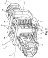
- the embodiment from figures 1 and 2 is provided with twelve sockets 5.
- the sockets 5 are arranged so that there are six sockets 5 on each side of the longitudinal plane.
- the embodiment from figure 3 is provided with four sockets 5. These sockets 5 are arranged so that there are two sockets 5 on each side of the longitudinal plane.
- sockets 5 there can be any number of sockets 5.
- the number of the sockets 5 and their arrangement are the same on each interface zone 4 of the base unit 1.
- the number of the sockets 5 and their arrangement can differ between the two interface zones 4.
- each socket 5 is a hole 6.
- a centering pin or a bolt both are not shown in the figures.
- An embodiment of the present invention also relates to a kit for assembling a crankcase 101.
- kit comprises one or more base units 1, such as the one described above.
- a suitable number of connecting devices is provides, so that the base units 1 can be attached together.
- the base units 1 can be attached on their respective interface zones 4, as explained above.
- a spacer device 15 can be inserted between two base units 1.
- Such spacer device is used in case the cylinders that have to be attached to the crankcase 101 are particularly large. Indeed, if that is the case, a suitable spacer device 15 used so that enough space is restored between two base units 1.
- the spacer device 15 has two ends 15a, which are opposite and which can be attached to a respective base unit 1 as will be explained in a following part of the present disclosure.
- the spacer device 15 comprises at least a perimetral wall 14. In use, such perimetral wall 14 extends around the crankshaft 100.
- the spacer device 15 comprises just one perimetral wall 14 which is U-shaped. This particular shape of the spacer device 15 allows the admittance of the crankshaft from the open side of spacer device 15.
- Both spacer device 15 and base unit 1 have the open sides face on the same side in order to allow the entry of the crankshaft 100.
- the spacer device 15 can comprise any number of perimetral walls 14 which can be arranged differently.
- the spacer device 15 is configured to be connected to the base units 1 onto the respective interface zones 4.
- the spacer device 15 has a pair of interface zones 16 itself. These interface zones 16 are opposite to each other. In other words, the interface zones 16 are placed each onto a respective end 15a of the spacer device 15.
- the interface zones 16 are configured to be attached to respective interface zones 4 of respective base units 1. For this reason, the interface zones 16 are substantially similar to the interface zones 4 of the base unit 1, therefore they will not be further detailed in the present disclosure.
- the kit can also comprise a crankshaft 100 configured to be inserted into the housing 2 of the base unit 1.
- the crankshaft 100 comprises a plurality of segments 102.
- Each segment 102 is configured to be housed into a respective base unit 1 and to be joined with at least another segment 102 in order to define the crankshaft 101.
- the crankshaft 100 is also modular, being composed by a variable number of segments 102.
- each segment 102 has a length substantially equal to the length of its respective base unit 1 along the longitudinal axis "A".
- the number of segments 102 is preferably the same as the number of base units 1 in the crankcase.
- each segment 102 is configured to be attached to two connecting rods.
- crankshaft may comprise one or more further segment 103.
- Each further segment 103 is configured to be attached to two segments 102.
- each further segment 103 has the same length along the longitudinal axis "A" as the spacer device 15. Indeed, in use, each further segment 103 is placed inside the spacer device 15.
- the base units 1 have all the same length along the longitudinal axis "A".
- this enables a better modularity for the crankcase 101 built using the above described kit.
- length can vary depending on design specification.
- a single kit can comprise base units 1 of different length or size.
- Another embodiment of the present invention relates to a method for assembling the above described crankcase 101. Two or more of the base units 1 are provided with the appropriate number of spacer device 15.
- base units 1 are attached to each other.
- spacer devices 15 are used, they are each inserted between two base units 1.
- the interface zones 4, 16 are joined.
- pins are inserted inside a subset of sockets 5.
- the remaining sockets 5 of adjacent interface zones 4, 16 are then secured with bolts.
- a crankshaft is inserted in the seats 9 of the base units 1. If necessary, a crankshaft 100 is assembled by any required number of segments 102 and further segments 103, which are joined by means known to the person skilled in the art.
- Another embodiment of the present invention relates to a method of upgrading a crankcase 101, for example if an additional pair of pistons (with respective connecting rods) is deemed necessary.
- another base unit 1 is attached to a base unit 1 already part of the crankcase 101, in particular at one end of the crankcase 101.
- a spacer device 15 can be inserted between the previous crankcase 101 and the new base unit 1.
- a known single-piece crankshaft was installed in the previous crankcase 101 it has to be replaced. Otherwise, if the above discussed crankshaft 100 was used, it can be adjusted by adding a new segment 102 and, if required, a new further segment 103. Any number of base units 1 can be added this way.
Landscapes
- Engineering & Computer Science (AREA)
- Mechanical Engineering (AREA)
- General Engineering & Computer Science (AREA)
- Compressors, Vaccum Pumps And Other Relevant Systems (AREA)
- Compressor (AREA)
Description
- The present invention relates to a base unit for assembling a crankcase of a reciprocating compressor.
- A crankcase for a reciprocating compressor is known in the art. Such crankcase is designed to hold the crankshaft, which is placed along a predefined orientation. The orientation of the crankshaft defines a longitudinal axis of the crankcase. Such crankcase comprises a housing, which has the function to hold the crankshaft. The housing has two sidewalls, which develops substantially parallel to each other and to the longitudinal axis of the crankcase.
- A plurality of access port is located on the side walls. Each access port allows a respective connecting rod, which is in turn connected to a piston, to attach to the crankshaft. The access port are arranged on the side walls in such a way as to balance the load on the crankshaft itself during the normal functioning of the compressor.
- A disadvantage of the known crankcase is that it is manufactured by casting and it is tailor-made for the specific application. This also applies to very big crankcases, which can house for example a crankshaft with up to ten pistons. Therefore, a faulty cast has the consequence of wasting an entire crankcase, with corresponding productivity and economic losses.
- A crankcase according to the state of the art is disclosed in prior art document
US 4,714,060 A . - A first aspect of the invention is therefore a base unit for assembling a crankcase of a reciprocating compressor. Such base unit comprises a housing configured to hold at least part of a crankshaft. An access port is placed onto the housing, and is configured to hold a connecting rod attached to a piston. The base unit has at least an interface zone, also placed on the housing, which is configured to be coupled with another interface zone of another base unit in order to assemble the crankcase.
- An advantage of the base unit is that it allows a modular approach to the assembling a crankcase, since many base unit can be assemble in order to build a crankcase according to the specifications. In turn, this allows an increased productivity of the fabrication process.
- A second aspect of the invention is a kit for assembling a crankcase comprising a plurality of base units. At least a connecting device is provided in order to attach the base units to each other onto the respective interface zones. This allows to optimize the assembly procedure for the reciprocating compressors.
- A third aspect of the invention is a crankcase comprising at least a base unit as described above.
- A fourth aspect of the invention is therefore directed to a method for assembling the crankcase. The method comprises the steps of providing at least two base units and attaching the base units to each other onto the respective interface zones.
- A fifth aspect of the invention is therefore directed to a method for upgrading a crankcase. This method comprises the step of providing a further base unit. This further base unit can be attached to the crankcase, in particular by placing an interface zone of the new base unit into contact with the interface zone of a base unit already part of the crankcase. This has the advantage of being able to update an already built crankcase instead of having to build a new one.
- Further details and specific embodiments will refer to the attached drawings, in which:
-
Figure 1 and2 are perspective views of a first embodiment of a base unit for assembling a crankcase of a reciprocating compressor; and -
Figure 3 is a perspective view of a detail of a second embodiment of a base unit for assembling a crankcase of a reciprocating compressor. - The following description of exemplary embodiments refers to the accompanying drawings. The same reference numbers in different drawings identify the same or similar elements. The following detailed description does not limit the invention. Instead, the scope of the invention is defined by the appended claims.
- Reference throughout the specification to "one embodiment" or "an embodiment" means that a particular feature, structure, or characteristic described in connection with an embodiment is included in at least one embodiment of the subject matter disclosed. Thus, the appearance of the phrases "in one embodiment" or "in an embodiment" in various places throughout the specification is not necessarily referring to the same embodiment. Further, the particular features, structures or characteristics may be combined in any suitable manner in one or more embodiments.
- Therefore, a base unit for assembling a
crankcase 101 of a reciprocating compressor will be described, also referring the attached figures in which it will be indicated with thenumber 1. - The
base unit 1 comprises ahousing 2, which is configured to hold at least part of acrankshaft 100. Indeed, thehousing 2 has a longitudinal axis "A", which defines an orientation for thecrankshaft 100. Thehousing 2 has a first 2a and asecond end 2b, opposite to each other and substantially aligned along the longitudinal axis "A". The longitudinal axis "A" lays on a longitudinal plane which is transversal with respect to both the first 2a and thesecond end 2b. - The
housing 2 is substantially U-shaped and has an open side from which thecrankshaft 100 can be inserted. Once thecrankshaft 2 has been placed in thehousing 2, a pluralities ofcrosspieces 17 are installed on thehousing 2 in order to increase the structural rigidity of thehousing 2 itself. - With additional detail, the
housing 2 comprises asupport plate 11. Thesupport plate 11 is preferably rectangular in shape, and is configured to rest onto a support surface (not shown). - Preferably, the
housing 2 has twoend walls 8, which are placed on theends housing 2. Theend walls 8 are substantially perpendicular to the above mentioned longitudinal plane. More preferably, theend walls 8 are substantially parallel to each other. In use, theend walls 8 are oriented substantially in a vertical direction, and thus are transversal, and preferably perpendicular, to thesupport plate 11. - With more detail, each
end wall 8 has a seat 9 configured to accept acrankshaft 100 of suitable size. In particular, the seat 9 has a concave, preferably semicircular shape so that it is able to receive bearings (not shown). Aclosure 12 can be placed onto the seat 9 in order to lock theshaft 100 in the seat 9. - The
housing 2 also comprises twoside walls 10, placed transversally and preferably perpendicularly to the above mentionedend walls 8. Theside walls 10 are substantially parallel to each other.Such side walls 10 are each attached to afurther housing 13, which is designed to hold a crosshead for a piston (not shown in the drawings). According to different embodiments of the invention, thefurther housings 13 can either be made as a single piece with thehousing 2 or they can be built separately and then attached to thehousing 2 in a later phase. - With more detail, an
access port 3 is placed onto thehousing 2.Such access port 3 is configured to hold a connecting rod for a piston (not shown in the drawings). Specifically, theaccess port 3 is placed onto theside wall 10, so that the above mentioned connecting rod can link the crosshead to theshaft 100 inside thebase unit 1. In the embodiments shown in the figures eachside wall 10 has asingle access port 3. In different embodiments, not shown, each side wall can have more than oneaccess port 3. - According to the embodiments shown in the attached figures, the
base unit 1 has at least aninterface zone 4 on thehousing 2. Preferably, theinterface zone 4 lays on a plane transversal to the longitudinal axis "A" of thehousing 2. In detail, theinterface zone 4 is configured to be coupled with anotherinterface zone 4 of thebase unit 1 for assembling thecrankcase 101. In other words, twobase units 1 can be joined together in order to assemble acrankcase 101. Details on the method for assembling acrankcase 101 will be given in a following portion of the present disclosure. - The
base unit 1 has twointerface zones 4, which are placed respectively onto the first 2a and onto thesecond end 2b of thehousing 2. Indeed, theinterface zones 4 are parallel to each other. Advantageously, this allows to chain-link an arbitrary number ofbase units 1. With additional detail, eachinterface zone 4 is placed onto arespective end wall 8. In particular, eachinterface zone 4 is placed onto anouter surface 8a of theend walls 8. The base units are arranged so that their open sides face on the same side. - With additional detail, the
interface zone 4 is provided with at least asocket 5, which is configured to receive a connecting device (not shown). The connecting device has the function of fixing theinterface zone 4 to anotherbase unit 1. Preferably, theinterface zone 4 is provided with at least twosockets 5, placed on opposite sides of the longitudinal plane of thehousing 2. Indeed, in the embodiments shown in the figures theinterface zone 4 is provided with a plurality ofsockets 5, placed substantially symmetrically with respect to the longitudinal plane. - With greater detail, the embodiment from
figures 1 and2 is provided with twelvesockets 5. Specifically, thesockets 5 are arranged so that there are sixsockets 5 on each side of the longitudinal plane. - Similarly, the embodiment from
figure 3 is provided with foursockets 5. Thesesockets 5 are arranged so that there are twosockets 5 on each side of the longitudinal plane. - In further embodiments, not shown in the drawings, there can be any number of
sockets 5. Preferably, the number of thesockets 5 and their arrangement are the same on eachinterface zone 4 of thebase unit 1. Alternatively, if justified by design considerations, the number of thesockets 5 and their arrangement can differ between the twointerface zones 4. - According to the embodiments shown in the attached figures, each
socket 5 is a hole 6. Advantageously, either a centering pin or a bolt (both are not shown in the figures) can be installed in the holes 6. - An embodiment of the present invention also relates to a kit for assembling a
crankcase 101. Such kit comprises one ormore base units 1, such as the one described above. A suitable number of connecting devices is provides, so that thebase units 1 can be attached together. In particular, thebase units 1 can be attached on theirrespective interface zones 4, as explained above. - Optionally a
spacer device 15 can be inserted between twobase units 1. Such spacer device is used in case the cylinders that have to be attached to thecrankcase 101 are particularly large. Indeed, if that is the case, asuitable spacer device 15 used so that enough space is restored between twobase units 1. Specifically, thespacer device 15 has twoends 15a, which are opposite and which can be attached to arespective base unit 1 as will be explained in a following part of the present disclosure. - With greater detail, the
spacer device 15 comprises at least aperimetral wall 14. In use,such perimetral wall 14 extends around thecrankshaft 100. In the embodiment shown the figures, thespacer device 15 comprises just oneperimetral wall 14 which is U-shaped. This particular shape of thespacer device 15 allows the admittance of the crankshaft from the open side ofspacer device 15. Bothspacer device 15 andbase unit 1 have the open sides face on the same side in order to allow the entry of thecrankshaft 100. In alternative embodiments, not shown, thespacer device 15 can comprise any number ofperimetral walls 14 which can be arranged differently. - In detail, the
spacer device 15 is configured to be connected to thebase units 1 onto therespective interface zones 4. Indeed, thespacer device 15 has a pair ofinterface zones 16 itself. Theseinterface zones 16 are opposite to each other. In other words, theinterface zones 16 are placed each onto arespective end 15a of thespacer device 15. Theinterface zones 16 are configured to be attached torespective interface zones 4 ofrespective base units 1. For this reason, theinterface zones 16 are substantially similar to theinterface zones 4 of thebase unit 1, therefore they will not be further detailed in the present disclosure. - Although a known crankshaft can be used with the
crankcase 101 according to the above described embodiment of the invention, the kit can also comprise acrankshaft 100 configured to be inserted into thehousing 2 of thebase unit 1. In detail, thecrankshaft 100 comprises a plurality ofsegments 102. Eachsegment 102 is configured to be housed into arespective base unit 1 and to be joined with at least anothersegment 102 in order to define thecrankshaft 101. In other words, thecrankshaft 100 is also modular, being composed by a variable number ofsegments 102. Advantageously, eachsegment 102 has a length substantially equal to the length of itsrespective base unit 1 along the longitudinal axis "A". Furthermore, the number ofsegments 102 is preferably the same as the number ofbase units 1 in the crankcase. Preferably, eachsegment 102 is configured to be attached to two connecting rods. - Additionally, the crankshaft may comprise one or more
further segment 103. Eachfurther segment 103 is configured to be attached to twosegments 102. Preferably, eachfurther segment 103 has the same length along the longitudinal axis "A" as thespacer device 15. Indeed, in use, eachfurther segment 103 is placed inside thespacer device 15. - Preferably, in each kit according to the embodiments of the present invention the
base units 1 have all the same length along the longitudinal axis "A". Advantageously, this enables a better modularity for thecrankcase 101 built using the above described kit. Of course such length can vary depending on design specification. Furthermore, if necessary a single kit can comprisebase units 1 of different length or size. - Another embodiment of the present invention relates to a method for assembling the above described
crankcase 101. Two or more of thebase units 1 are provided with the appropriate number ofspacer device 15. - These
base units 1 are attached to each other. Optionally, if thespacer devices 15 are used, they are each inserted between twobase units 1. Theinterface zones sockets 5. The remainingsockets 5 ofadjacent interface zones base units 1. If necessary, acrankshaft 100 is assembled by any required number ofsegments 102 andfurther segments 103, which are joined by means known to the person skilled in the art. - Another embodiment of the present invention relates to a method of upgrading a
crankcase 101, for example if an additional pair of pistons (with respective connecting rods) is deemed necessary. In this case, anotherbase unit 1 is attached to abase unit 1 already part of thecrankcase 101, in particular at one end of thecrankcase 101. If necessary, aspacer device 15 can be inserted between theprevious crankcase 101 and thenew base unit 1. Also, if a known single-piece crankshaft was installed in theprevious crankcase 101 it has to be replaced. Otherwise, if the above discussedcrankshaft 100 was used, it can be adjusted by adding anew segment 102 and, if required, a newfurther segment 103. Any number ofbase units 1 can be added this way.
Claims (15)
- Base unit (1) for assembling a crankcase (101) of a reciprocal compressor, comprising a housing (2) configured to hold at least part of a crankshaft (100), said housing (2) having a first (2a) and a second end (2b) opposite to each other and substantially aligned along a longitudinal axis (A) and defining an orientation for said crankshaft (100); an access port (3) placed onto said housing (2) and configured to hold a connecting rod for a piston; wherein the base unit (1) has two interface zones (4) placed respectively onto the first (2a) and onto the second end (2b) of said housing (2), each interface zone (4) laying on a plane transversal to said longitudinal axis (A), each interface zone (4) being configured to be coupled with another interface zone (4) of another base unit (1) for assembling said crankcase (101), said base unit (1) being characterized in that said housing (2) is substantially U-shaped in order to have an open side face (17) from which said at least a part of a crankshaft (100) can be inserted by displacing it in direction transversal to said longitudinal axis (A).
- Base unit (1) according to the previous claim, wherein said interface zones (4) are parallel to each other.
- Base unit (1) according to any one of the previous claims, wherein said interface zone (4) is provided with at least a socket (5) configured to receive a connecting device for fixing said interface zone (4) to another base unit (1).
- Base unit (1) according to the previous claim, wherein said socket (5) comprises a hole (6) adapted to receive either a screw or a pin.
- Base unit (1) according to any one of the preceding claims, wherein the housing (2) has two end walls (8), which are placed on the ends (2a, 2b) of the housing (2) laying on said transversal planes, each end wall (8) having a seat (9) configured to accept a crankshaft (100) of suitable size, wherein the seat (9) of each end wall (8) has a concave, preferably semicircular, shape so that it is able to receive bearings.
- Kit for assembling a crankcase (101) comprising a plurality of base units (1) according to any one of the previous claims, also comprising at least a connecting device configured to attach two of said base units (1) to each other onto the respective interface zones (4).
- Kit according to the previous claim, also comprising a spacer device (15) insertable between two base units (1) and configured to be connected to said base units (1) onto the respective interface zones (4).
- Kit according to the previous claim, wherein said spacer device (15) has two interface zones (16) opposite to each other and configured to be attached to respective interface zones (4) of respective base units (1).
- Kit according to claim 7 or 8, wherein said spacer device (15) comprises at least a perimetral wall (14) for extending around a part of the crankshaft (100), said perimetral wall (14) being U-shaped for allowing the admittance of the crankshaft (100) from the open side of the spacer device (15), wherein both spacer device (15) and the base units (1) have the open sides face on the same side in order to allow the entry of the crankshaft (100).
- Kit according to any of the claims from 6 to 9, also comprising a crankshaft (100) configured to be inserted into said housing (2).
- Kit according to the previous claim, wherein said crankshaft (100) comprises a plurality of segments (102) for assembling said crankshaft (100), each crankshaft segment (102) being configured to be housed into a respective base unit (1) and to be joined with at least another crankshaft segment (102) in order to define said crankshaft (100).
- Kit according to the previous claim, wherein each segment (102) has a length substantially equal to the length of its respective base unit (1) along said longitudinal axis (A).
- Crankcase (101) comprising a plurality of base units (1) according to any of the claims from 1 to 5.
- Method for assembling a crankcase (101) according to claim 13, comprising the steps of providing at least two of said base units (1); attaching said base units (1) to each other onto the respective interface zones (4).
- Method for upgrading a crankcase (101) according to claim 13, comprising the steps of providing a further base unit (1), attaching said further base unit (1) to said crankcase (101).
Priority Applications (1)
| Application Number | Priority Date | Filing Date | Title |
|---|---|---|---|
| PL15703618T PL3105454T3 (en) | 2014-02-12 | 2015-02-11 | Base unit for assembling a crankcase of a reciprocating compressor |
Applications Claiming Priority (2)
| Application Number | Priority Date | Filing Date | Title |
|---|---|---|---|
| ITCO20140003 | 2014-02-12 | ||
| PCT/EP2015/052886 WO2015121310A1 (en) | 2014-02-12 | 2015-02-11 | Base unit for assembling a crankcase of a reciprocal compressor |
Publications (2)
| Publication Number | Publication Date |
|---|---|
| EP3105454A1 EP3105454A1 (en) | 2016-12-21 |
| EP3105454B1 true EP3105454B1 (en) | 2020-09-23 |
Family
ID=50486961
Family Applications (1)
| Application Number | Title | Priority Date | Filing Date |
|---|---|---|---|
| EP15703618.7A Active EP3105454B1 (en) | 2014-02-12 | 2015-02-11 | Base unit for assembling a crankcase of a reciprocating compressor |
Country Status (5)
| Country | Link |
|---|---|
| US (1) | US20160348664A1 (en) |
| EP (1) | EP3105454B1 (en) |
| ES (1) | ES2835879T3 (en) |
| PL (1) | PL3105454T3 (en) |
| WO (1) | WO2015121310A1 (en) |
Families Citing this family (2)
| Publication number | Priority date | Publication date | Assignee | Title |
|---|---|---|---|---|
| US10087921B2 (en) * | 2016-01-27 | 2018-10-02 | Ge Oil & Gas Compression Systems, Llc | Preventing deformation of frame on a reciprocating compressor |
| JP7049418B2 (en) * | 2020-09-10 | 2022-04-06 | 株式会社三井E&Sマシナリー | Manufacturing method of crankcase, cap member and crankcase |
Citations (4)
| Publication number | Priority date | Publication date | Assignee | Title |
|---|---|---|---|---|
| US2491630A (en) * | 1946-08-05 | 1949-12-20 | Compact Power Products Inc | Engine constructed of sections bolted together along vertical plane to form an entire head, block, and crankcase thereof |
| US4468174A (en) * | 1981-11-30 | 1984-08-28 | Oime, Inc. | Helicopter transportable mud pump |
| US4714060A (en) * | 1986-02-04 | 1987-12-22 | R K W Industries, Inc. | Composite engine |
| WO2008142512A2 (en) * | 2007-05-17 | 2008-11-27 | Dresser Italia S.R.L. | Frame for fluid machines |
Family Cites Families (7)
| Publication number | Priority date | Publication date | Assignee | Title |
|---|---|---|---|---|
| US851616A (en) * | 1906-04-02 | 1907-04-23 | John Francis Connell | Device for opening, closing, and locking doors. |
| US1964679A (en) * | 1932-09-28 | 1934-06-26 | Garland P Springfield | Compressor |
| US2650018A (en) * | 1945-02-23 | 1953-08-25 | Joy Mfg Co | Compressor |
| DE10345406A1 (en) * | 2002-10-14 | 2004-04-22 | Crt Common Rail Technologies Ag | High pressure pump for especially common rail fuel injection systems in internal combustion engines has individual modular feed pump units joined together in series by housings which have fluid connecting passages |
| GB2463821B (en) * | 2005-05-17 | 2010-06-09 | Thomas Industries Inc | Pump improvements |
| JP4205119B2 (en) * | 2006-06-27 | 2009-01-07 | シャープ株式会社 | Heterojunction field effect transistor and method of manufacturing heterojunction field effect transistor |
| WO2009070876A1 (en) * | 2007-12-06 | 2009-06-11 | Gerald Lesko | Mud pump |
-
2015
- 2015-02-11 WO PCT/EP2015/052886 patent/WO2015121310A1/en not_active Ceased
- 2015-02-11 ES ES15703618T patent/ES2835879T3/en active Active
- 2015-02-11 EP EP15703618.7A patent/EP3105454B1/en active Active
- 2015-02-11 PL PL15703618T patent/PL3105454T3/en unknown
- 2015-02-11 US US15/117,292 patent/US20160348664A1/en not_active Abandoned
Patent Citations (4)
| Publication number | Priority date | Publication date | Assignee | Title |
|---|---|---|---|---|
| US2491630A (en) * | 1946-08-05 | 1949-12-20 | Compact Power Products Inc | Engine constructed of sections bolted together along vertical plane to form an entire head, block, and crankcase thereof |
| US4468174A (en) * | 1981-11-30 | 1984-08-28 | Oime, Inc. | Helicopter transportable mud pump |
| US4714060A (en) * | 1986-02-04 | 1987-12-22 | R K W Industries, Inc. | Composite engine |
| WO2008142512A2 (en) * | 2007-05-17 | 2008-11-27 | Dresser Italia S.R.L. | Frame for fluid machines |
Also Published As
| Publication number | Publication date |
|---|---|
| US20160348664A1 (en) | 2016-12-01 |
| PL3105454T3 (en) | 2021-04-06 |
| ES2835879T3 (en) | 2021-06-23 |
| EP3105454A1 (en) | 2016-12-21 |
| WO2015121310A1 (en) | 2015-08-20 |
Similar Documents
| Publication | Publication Date | Title |
|---|---|---|
| US12203296B2 (en) | Hidden vehicle door handle mounting mechanism and vehicle | |
| US8371458B2 (en) | Ceiling rack | |
| RU2643387C2 (en) | Module of multiple use, intended for manufacturing of at least one part of the wall of the facility that is subject to the unlimited disassembly | |
| CN107076139B (en) | Power end frame assembly for reciprocating pump | |
| WO2015121310A1 (en) | Base unit for assembling a crankcase of a reciprocal compressor | |
| US11333297B2 (en) | Device for strengthening and rigging trusses and method in which such device is applied | |
| US9771960B2 (en) | Connection arrangement of at least two bodies, in particular at least two bodies of components of a mechanical automation group of movements, with a removable constraining group | |
| RU2462619C1 (en) | Compressor device of unit design | |
| KR101863876B1 (en) | Prefabricated desk | |
| RU2639451C1 (en) | Universal modular portal power frame for static and cyclic bench test of parts and bodies of turbo machinery | |
| US9888604B2 (en) | Support rack for at least one item of aircraft electronics, corresponding support device and aircraft | |
| AU2012338487B2 (en) | A metal structure with heavy duty corner elements | |
| JP3204299U (en) | Battery mount | |
| CN211392060U (en) | Supporting device and cold chain transportation equipment | |
| CN108994759B (en) | Positioning tool and electric box assembly line with same | |
| EP3088226A1 (en) | Engine apparatus support structure, and engine apparatus installation method | |
| US20240183375A1 (en) | Connecting device for securing two beams to each other, a method for using the connecting device, and tower including the connecting device | |
| JP2020125645A (en) | Framework structure | |
| EP3792510A1 (en) | A connecting rod | |
| KR101877907B1 (en) | A Joint for Connecting a Plural Axes | |
| US10364934B1 (en) | Support structure for supporting a conduit of an engine | |
| RU2270387C1 (en) | Device for connecting ropes | |
| RU106687U1 (en) | BLOCK COMPRESSOR UNIT | |
| JP3223743U (en) | Fixing tool for supporting member fixing means for formwork, and concrete casting mold formed using this fixing tool | |
| CN109973235A (en) | A kind of fixation kit |
Legal Events
| Date | Code | Title | Description |
|---|---|---|---|
| PUAI | Public reference made under article 153(3) epc to a published international application that has entered the european phase |
Free format text: ORIGINAL CODE: 0009012 |
|
| STAA | Information on the status of an ep patent application or granted ep patent |
Free format text: STATUS: REQUEST FOR EXAMINATION WAS MADE |
|
| 17P | Request for examination filed |
Effective date: 20160912 |
|
| AK | Designated contracting states |
Kind code of ref document: A1 Designated state(s): AL AT BE BG CH CY CZ DE DK EE ES FI FR GB GR HR HU IE IS IT LI LT LU LV MC MK MT NL NO PL PT RO RS SE SI SK SM TR |
|
| AX | Request for extension of the european patent |
Extension state: BA ME |
|
| DAX | Request for extension of the european patent (deleted) | ||
| STAA | Information on the status of an ep patent application or granted ep patent |
Free format text: STATUS: EXAMINATION IS IN PROGRESS |
|
| 17Q | First examination report despatched |
Effective date: 20190531 |
|
| REG | Reference to a national code |
Ref country code: DE Ref legal event code: R079 Ref document number: 602015059461 Country of ref document: DE Free format text: PREVIOUS MAIN CLASS: F04B0027053000 Ipc: F04B0027020000 |
|
| RIC1 | Information provided on ipc code assigned before grant |
Ipc: F04B 27/02 20060101AFI20200312BHEP Ipc: F04B 39/00 20060101ALI20200312BHEP Ipc: F04B 27/04 20060101ALI20200312BHEP Ipc: F04B 39/12 20060101ALI20200312BHEP Ipc: F04B 27/053 20060101ALI20200312BHEP |
|
| GRAP | Despatch of communication of intention to grant a patent |
Free format text: ORIGINAL CODE: EPIDOSNIGR1 |
|
| STAA | Information on the status of an ep patent application or granted ep patent |
Free format text: STATUS: GRANT OF PATENT IS INTENDED |
|
| INTG | Intention to grant announced |
Effective date: 20200423 |
|
| GRAS | Grant fee paid |
Free format text: ORIGINAL CODE: EPIDOSNIGR3 |
|
| GRAA | (expected) grant |
Free format text: ORIGINAL CODE: 0009210 |
|
| STAA | Information on the status of an ep patent application or granted ep patent |
Free format text: STATUS: THE PATENT HAS BEEN GRANTED |
|
| AK | Designated contracting states |
Kind code of ref document: B1 Designated state(s): AL AT BE BG CH CY CZ DE DK EE ES FI FR GB GR HR HU IE IS IT LI LT LU LV MC MK MT NL NO PL PT RO RS SE SI SK SM TR |
|
| REG | Reference to a national code |
Ref country code: GB Ref legal event code: FG4D |
|
| REG | Reference to a national code |
Ref country code: CH Ref legal event code: EP |
|
| REG | Reference to a national code |
Ref country code: IE Ref legal event code: FG4D |
|
| REG | Reference to a national code |
Ref country code: AT Ref legal event code: REF Ref document number: 1316631 Country of ref document: AT Kind code of ref document: T Effective date: 20201015 Ref country code: DE Ref legal event code: R096 Ref document number: 602015059461 Country of ref document: DE |
|
| PG25 | Lapsed in a contracting state [announced via postgrant information from national office to epo] |
Ref country code: FI Free format text: LAPSE BECAUSE OF FAILURE TO SUBMIT A TRANSLATION OF THE DESCRIPTION OR TO PAY THE FEE WITHIN THE PRESCRIBED TIME-LIMIT Effective date: 20200923 Ref country code: SE Free format text: LAPSE BECAUSE OF FAILURE TO SUBMIT A TRANSLATION OF THE DESCRIPTION OR TO PAY THE FEE WITHIN THE PRESCRIBED TIME-LIMIT Effective date: 20200923 Ref country code: NO Free format text: LAPSE BECAUSE OF FAILURE TO SUBMIT A TRANSLATION OF THE DESCRIPTION OR TO PAY THE FEE WITHIN THE PRESCRIBED TIME-LIMIT Effective date: 20201223 Ref country code: GR Free format text: LAPSE BECAUSE OF FAILURE TO SUBMIT A TRANSLATION OF THE DESCRIPTION OR TO PAY THE FEE WITHIN THE PRESCRIBED TIME-LIMIT Effective date: 20201224 Ref country code: BG Free format text: LAPSE BECAUSE OF FAILURE TO SUBMIT A TRANSLATION OF THE DESCRIPTION OR TO PAY THE FEE WITHIN THE PRESCRIBED TIME-LIMIT Effective date: 20201223 Ref country code: HR Free format text: LAPSE BECAUSE OF FAILURE TO SUBMIT A TRANSLATION OF THE DESCRIPTION OR TO PAY THE FEE WITHIN THE PRESCRIBED TIME-LIMIT Effective date: 20200923 |
|
| REG | Reference to a national code |
Ref country code: AT Ref legal event code: MK05 Ref document number: 1316631 Country of ref document: AT Kind code of ref document: T Effective date: 20200923 |
|
| PG25 | Lapsed in a contracting state [announced via postgrant information from national office to epo] |
Ref country code: LV Free format text: LAPSE BECAUSE OF FAILURE TO SUBMIT A TRANSLATION OF THE DESCRIPTION OR TO PAY THE FEE WITHIN THE PRESCRIBED TIME-LIMIT Effective date: 20200923 Ref country code: RS Free format text: LAPSE BECAUSE OF FAILURE TO SUBMIT A TRANSLATION OF THE DESCRIPTION OR TO PAY THE FEE WITHIN THE PRESCRIBED TIME-LIMIT Effective date: 20200923 |
|
| REG | Reference to a national code |
Ref country code: NL Ref legal event code: MP Effective date: 20200923 |
|
| REG | Reference to a national code |
Ref country code: LT Ref legal event code: MG4D |
|
| PG25 | Lapsed in a contracting state [announced via postgrant information from national office to epo] |
Ref country code: CZ Free format text: LAPSE BECAUSE OF FAILURE TO SUBMIT A TRANSLATION OF THE DESCRIPTION OR TO PAY THE FEE WITHIN THE PRESCRIBED TIME-LIMIT Effective date: 20200923 Ref country code: RO Free format text: LAPSE BECAUSE OF FAILURE TO SUBMIT A TRANSLATION OF THE DESCRIPTION OR TO PAY THE FEE WITHIN THE PRESCRIBED TIME-LIMIT Effective date: 20200923 Ref country code: SM Free format text: LAPSE BECAUSE OF FAILURE TO SUBMIT A TRANSLATION OF THE DESCRIPTION OR TO PAY THE FEE WITHIN THE PRESCRIBED TIME-LIMIT Effective date: 20200923 Ref country code: EE Free format text: LAPSE BECAUSE OF FAILURE TO SUBMIT A TRANSLATION OF THE DESCRIPTION OR TO PAY THE FEE WITHIN THE PRESCRIBED TIME-LIMIT Effective date: 20200923 Ref country code: PT Free format text: LAPSE BECAUSE OF FAILURE TO SUBMIT A TRANSLATION OF THE DESCRIPTION OR TO PAY THE FEE WITHIN THE PRESCRIBED TIME-LIMIT Effective date: 20210125 Ref country code: LT Free format text: LAPSE BECAUSE OF FAILURE TO SUBMIT A TRANSLATION OF THE DESCRIPTION OR TO PAY THE FEE WITHIN THE PRESCRIBED TIME-LIMIT Effective date: 20200923 Ref country code: NL Free format text: LAPSE BECAUSE OF FAILURE TO SUBMIT A TRANSLATION OF THE DESCRIPTION OR TO PAY THE FEE WITHIN THE PRESCRIBED TIME-LIMIT Effective date: 20200923 |
|
| PG25 | Lapsed in a contracting state [announced via postgrant information from national office to epo] |
Ref country code: AT Free format text: LAPSE BECAUSE OF FAILURE TO SUBMIT A TRANSLATION OF THE DESCRIPTION OR TO PAY THE FEE WITHIN THE PRESCRIBED TIME-LIMIT Effective date: 20200923 Ref country code: AL Free format text: LAPSE BECAUSE OF FAILURE TO SUBMIT A TRANSLATION OF THE DESCRIPTION OR TO PAY THE FEE WITHIN THE PRESCRIBED TIME-LIMIT Effective date: 20200923 Ref country code: IS Free format text: LAPSE BECAUSE OF FAILURE TO SUBMIT A TRANSLATION OF THE DESCRIPTION OR TO PAY THE FEE WITHIN THE PRESCRIBED TIME-LIMIT Effective date: 20210123 |
|
| REG | Reference to a national code |
Ref country code: ES Ref legal event code: FG2A Ref document number: 2835879 Country of ref document: ES Kind code of ref document: T3 Effective date: 20210623 |
|
| REG | Reference to a national code |
Ref country code: DE Ref legal event code: R097 Ref document number: 602015059461 Country of ref document: DE |
|
| PG25 | Lapsed in a contracting state [announced via postgrant information from national office to epo] |
Ref country code: SK Free format text: LAPSE BECAUSE OF FAILURE TO SUBMIT A TRANSLATION OF THE DESCRIPTION OR TO PAY THE FEE WITHIN THE PRESCRIBED TIME-LIMIT Effective date: 20200923 |
|
| PLBE | No opposition filed within time limit |
Free format text: ORIGINAL CODE: 0009261 |
|
| STAA | Information on the status of an ep patent application or granted ep patent |
Free format text: STATUS: NO OPPOSITION FILED WITHIN TIME LIMIT |
|
| PG25 | Lapsed in a contracting state [announced via postgrant information from national office to epo] |
Ref country code: DK Free format text: LAPSE BECAUSE OF FAILURE TO SUBMIT A TRANSLATION OF THE DESCRIPTION OR TO PAY THE FEE WITHIN THE PRESCRIBED TIME-LIMIT Effective date: 20200923 Ref country code: SI Free format text: LAPSE BECAUSE OF FAILURE TO SUBMIT A TRANSLATION OF THE DESCRIPTION OR TO PAY THE FEE WITHIN THE PRESCRIBED TIME-LIMIT Effective date: 20200923 |
|
| 26N | No opposition filed |
Effective date: 20210624 |
|
| PG25 | Lapsed in a contracting state [announced via postgrant information from national office to epo] |
Ref country code: MC Free format text: LAPSE BECAUSE OF FAILURE TO SUBMIT A TRANSLATION OF THE DESCRIPTION OR TO PAY THE FEE WITHIN THE PRESCRIBED TIME-LIMIT Effective date: 20200923 |
|
| GBPC | Gb: european patent ceased through non-payment of renewal fee |
Effective date: 20210211 |
|
| REG | Reference to a national code |
Ref country code: BE Ref legal event code: MM Effective date: 20210228 |
|
| PG25 | Lapsed in a contracting state [announced via postgrant information from national office to epo] |
Ref country code: IT Free format text: LAPSE BECAUSE OF FAILURE TO SUBMIT A TRANSLATION OF THE DESCRIPTION OR TO PAY THE FEE WITHIN THE PRESCRIBED TIME-LIMIT Effective date: 20200923 Ref country code: LU Free format text: LAPSE BECAUSE OF NON-PAYMENT OF DUE FEES Effective date: 20210211 |
|
| PG25 | Lapsed in a contracting state [announced via postgrant information from national office to epo] |
Ref country code: FR Free format text: LAPSE BECAUSE OF NON-PAYMENT OF DUE FEES Effective date: 20210228 Ref country code: GB Free format text: LAPSE BECAUSE OF NON-PAYMENT OF DUE FEES Effective date: 20210211 Ref country code: IE Free format text: LAPSE BECAUSE OF NON-PAYMENT OF DUE FEES Effective date: 20210211 |
|
| REG | Reference to a national code |
Ref country code: CH Ref legal event code: PK Free format text: BERICHTIGUNGEN |
|
| PGFP | Annual fee paid to national office [announced via postgrant information from national office to epo] |
Ref country code: PL Payment date: 20220119 Year of fee payment: 8 Ref country code: ES Payment date: 20220301 Year of fee payment: 8 |
|
| REG | Reference to a national code |
Ref country code: ES Ref legal event code: PC2A Owner name: NUOVO PIGNONE TECNOLOGIE - S.R.L. Effective date: 20220628 |
|
| PG25 | Lapsed in a contracting state [announced via postgrant information from national office to epo] |
Ref country code: BE Free format text: LAPSE BECAUSE OF NON-PAYMENT OF DUE FEES Effective date: 20210228 |
|
| PG25 | Lapsed in a contracting state [announced via postgrant information from national office to epo] |
Ref country code: HU Free format text: LAPSE BECAUSE OF FAILURE TO SUBMIT A TRANSLATION OF THE DESCRIPTION OR TO PAY THE FEE WITHIN THE PRESCRIBED TIME-LIMIT; INVALID AB INITIO Effective date: 20150211 |
|
| PG25 | Lapsed in a contracting state [announced via postgrant information from national office to epo] |
Ref country code: CY Free format text: LAPSE BECAUSE OF FAILURE TO SUBMIT A TRANSLATION OF THE DESCRIPTION OR TO PAY THE FEE WITHIN THE PRESCRIBED TIME-LIMIT Effective date: 20200923 |
|
| P01 | Opt-out of the competence of the unified patent court (upc) registered |
Effective date: 20230526 |
|
| REG | Reference to a national code |
Ref country code: ES Ref legal event code: FD2A Effective date: 20240405 |
|
| PG25 | Lapsed in a contracting state [announced via postgrant information from national office to epo] |
Ref country code: ES Free format text: LAPSE BECAUSE OF NON-PAYMENT OF DUE FEES Effective date: 20230212 |
|
| PG25 | Lapsed in a contracting state [announced via postgrant information from national office to epo] |
Ref country code: MK Free format text: LAPSE BECAUSE OF FAILURE TO SUBMIT A TRANSLATION OF THE DESCRIPTION OR TO PAY THE FEE WITHIN THE PRESCRIBED TIME-LIMIT Effective date: 20200923 Ref country code: ES Free format text: LAPSE BECAUSE OF NON-PAYMENT OF DUE FEES Effective date: 20230212 |
|
| PG25 | Lapsed in a contracting state [announced via postgrant information from national office to epo] |
Ref country code: TR Free format text: LAPSE BECAUSE OF FAILURE TO SUBMIT A TRANSLATION OF THE DESCRIPTION OR TO PAY THE FEE WITHIN THE PRESCRIBED TIME-LIMIT Effective date: 20200923 |
|
| REG | Reference to a national code |
Ref country code: DE Ref legal event code: R081 Ref document number: 602015059461 Country of ref document: DE Owner name: NUOVO PIGNONE TECNOLOGIE - S.R.L., IT Free format text: FORMER OWNER: NUOVO PIGNONE S.R.L., 50127 FLORENCE, IT |
|
| PG25 | Lapsed in a contracting state [announced via postgrant information from national office to epo] |
Ref country code: MT Free format text: LAPSE BECAUSE OF FAILURE TO SUBMIT A TRANSLATION OF THE DESCRIPTION OR TO PAY THE FEE WITHIN THE PRESCRIBED TIME-LIMIT Effective date: 20200923 |
|
| PG25 | Lapsed in a contracting state [announced via postgrant information from national office to epo] |
Ref country code: PL Free format text: LAPSE BECAUSE OF NON-PAYMENT OF DUE FEES Effective date: 20230211 |
|
| REG | Reference to a national code |
Ref country code: CH Ref legal event code: U11 Free format text: ST27 STATUS EVENT CODE: U-0-0-U10-U11 (AS PROVIDED BY THE NATIONAL OFFICE) Effective date: 20260301 |
|
| PGFP | Annual fee paid to national office [announced via postgrant information from national office to epo] |
Ref country code: DE Payment date: 20260121 Year of fee payment: 12 |
|
| PGFP | Annual fee paid to national office [announced via postgrant information from national office to epo] |
Ref country code: CH Payment date: 20260301 Year of fee payment: 12 |