EP3105409B1 - Plugging of a flow passage in a subterranean well - Google Patents
Plugging of a flow passage in a subterranean well Download PDFInfo
- Publication number
- EP3105409B1 EP3105409B1 EP14889493.4A EP14889493A EP3105409B1 EP 3105409 B1 EP3105409 B1 EP 3105409B1 EP 14889493 A EP14889493 A EP 14889493A EP 3105409 B1 EP3105409 B1 EP 3105409B1
- Authority
- EP
- European Patent Office
- Prior art keywords
- plug
- piston
- isolation tool
- isolation
- tool
- Prior art date
- Legal status (The legal status is an assumption and is not a legal conclusion. Google has not performed a legal analysis and makes no representation as to the accuracy of the status listed.)
- Active
Links
- 238000002955 isolation Methods 0.000 claims description 78
- 238000000034 method Methods 0.000 claims description 26
- 238000006073 displacement reaction Methods 0.000 claims description 21
- 230000004044 response Effects 0.000 claims description 7
- 230000008602 contraction Effects 0.000 claims 3
- 239000012530 fluid Substances 0.000 description 7
- 239000000463 material Substances 0.000 description 5
- 241000282472 Canis lupus familiaris Species 0.000 description 3
- 238000004891 communication Methods 0.000 description 3
- 238000007789 sealing Methods 0.000 description 2
- 238000006467 substitution reaction Methods 0.000 description 2
- 208000010392 Bone Fractures Diseases 0.000 description 1
- 206010017076 Fracture Diseases 0.000 description 1
- 208000006670 Multiple fractures Diseases 0.000 description 1
- 238000007792 addition Methods 0.000 description 1
- 230000009286 beneficial effect Effects 0.000 description 1
- 230000015572 biosynthetic process Effects 0.000 description 1
- 239000011248 coating agent Substances 0.000 description 1
- 238000000576 coating method Methods 0.000 description 1
- 238000012217 deletion Methods 0.000 description 1
- 230000037430 deletion Effects 0.000 description 1
- 239000013536 elastomeric material Substances 0.000 description 1
- 238000009434 installation Methods 0.000 description 1
- 238000004519 manufacturing process Methods 0.000 description 1
- 239000002184 metal Substances 0.000 description 1
- 238000012986 modification Methods 0.000 description 1
- 230000004048 modification Effects 0.000 description 1
- 230000008569 process Effects 0.000 description 1
- 239000012858 resilient material Substances 0.000 description 1
- 238000010008 shearing Methods 0.000 description 1
- 230000000638 stimulation Effects 0.000 description 1
Images


Classifications
-
- E—FIXED CONSTRUCTIONS
- E21—EARTH DRILLING; MINING
- E21B—EARTH DRILLING, e.g. DEEP DRILLING; OBTAINING OIL, GAS, WATER, SOLUBLE OR MELTABLE MATERIALS OR A SLURRY OF MINERALS FROM WELLS
- E21B23/00—Apparatus for displacing, setting, locking, releasing, or removing tools, packers or the like in the boreholes or wells
- E21B23/06—Apparatus for displacing, setting, locking, releasing, or removing tools, packers or the like in the boreholes or wells for setting packers
-
- E—FIXED CONSTRUCTIONS
- E21—EARTH DRILLING; MINING
- E21B—EARTH DRILLING, e.g. DEEP DRILLING; OBTAINING OIL, GAS, WATER, SOLUBLE OR MELTABLE MATERIALS OR A SLURRY OF MINERALS FROM WELLS
- E21B33/00—Sealing or packing boreholes or wells
- E21B33/10—Sealing or packing boreholes or wells in the borehole
- E21B33/12—Packers; Plugs
-
- E—FIXED CONSTRUCTIONS
- E21—EARTH DRILLING; MINING
- E21B—EARTH DRILLING, e.g. DEEP DRILLING; OBTAINING OIL, GAS, WATER, SOLUBLE OR MELTABLE MATERIALS OR A SLURRY OF MINERALS FROM WELLS
- E21B43/00—Methods or apparatus for obtaining oil, gas, water, soluble or meltable materials or a slurry of minerals from wells
- E21B43/14—Obtaining from a multiple-zone well
Definitions
- This disclosure relates generally to equipment utilized and operations performed in conjunction with a subterranean well and, in one example described below, more particularly provides an isolation tool for use in a well.
- US2012/168163 relates to a string that extends into a well and a tool that is disposed in the string.
- US4893678A relates to a downhole tool for multiple setting and unsetting operations in a well bore during a single trip.
- FIG. 1 Representatively illustrated in FIG. 1 is a system 10 for use with a well, and an associated method, which system and method can embody principles of this disclosure.
- system 10 and method are merely one example of an application of the principles of this disclosure in practice, and a wide variety of other examples are possible. Therefore, the scope of this disclosure is not limited at all to the details of the system 10 and method described herein and/or depicted in the drawings.
- a tubular string 12 (such as, a completion or production string) is positioned in casing 14 cemented in a wellbore 16.
- the tubular string 12 could be positioned in an uncased or open hole section of the wellbore 16, the tubular string could be the casing, the wellbore could be horizontal or inclined, etc.
- the scope of this disclosure is not limited to any particular arrangement or configuration of components in the system 10.
- the tubular string 12 includes packers 20a-c for sealing off an annulus 22 formed radially between the tubular string and the casing 14 (or wellbore 16). As depicted in FIG. 1 , the casing 14 is not perforated, and the annulus 22 is not otherwise in communication with the zones 18a-c, but the packers 20a-c will be useful for isolating the zones from each other when the annulus is in communication with the zones.
- the tubular string 12 also includes isolation tools 24a-c.
- each of the isolation tools 24a-c is depicted in FIG. 1 as being positioned longitudinally between a respective one of the packers 20a-c and an area of the tubular string 12 and the casing 14 to be perforated for a corresponding one of the zones 18a-c.
- this positioning of the isolation tools 24a-c may not be desirable in some circumstances.
- isolation tool 24c may not be used.
- the scope of this disclosure is not limited to any particular positions or relative positions of isolation tools in the system 10.
- Perforations 26 are formed through the tubular string 12 and casing 14 by a perforating gun 28 conveyed into a flow passage 30 of the tubular string on a conveyance 32.
- the conveyance 32 may be a wireline, slickline, coiled tubing or another type of conveyance.
- the conveyance 32 is capable of accurately positioning the perforating gun 28 for forming the perforations 26 through the tubular string 12, casing 14 and into the zone 18a.
- the annulus below the packer 20a is placed in communication with the zone 18a. Fluids can now be flowed from the flow passage 30 into the zone 18a (e.g., in stimulation, fracturing, conformance, steam- or water-flooding operations, etc.), and fluids can be produced from the zone into the tubular string 12.
- a shifting tool 66 is depicted in FIG. 2 as being connected below the perforating gun 28. Use of the shifting tool 66 is described more fully below, but it should be understood that it is not necessary to connect the shifting tool below the perforating gun 28. For example, the shifting tool 66 could be connected above the perforating gun 28, or could be separately conveyed into the passage 30.
- Fracturing of the zone 18a can be accomplished by flowing fluids, proppant, etc., from the tubular string 12 into the zone via the perforations 26.
- a plug 34a is set in the isolation tool 24a. This isolates the zone 18a from the flow passage 30 above the plug 34a, so that the flow passage above the plug can be used for perforating and fracturing the other zones 18b,c, without communicating with the fractured zone 18a.
- Each of the other zones 18b,c can be perforated and fractured as described above for the zone 18a. After each zone 18b,c is perforated and fractured, a plug is set in a respective one of the isolation tools 24b,c to isolate that zone.
- the system 10 is representatively illustrated after the zones 18a-c have been perforated and fractured. Additional zones (not shown) above and/or below the zones 18a-c may also be perforated and fractured. Note that plugs 34a-c remain in their respective isolation devices 24a-c after the corresponding zones 18a-c are fractured.
- fluids 36 can be produced into the tubular string 12 from all of the zones 18a-c, and can be flowed via the flow passage 30 to the earth's surface or another location.
- the plugs 34a-c can be retrieved (such as, by wireline, slickline or coiled tubing), drilled or milled through, or degraded.
- the plugs 34a-c could be made of a material that eventually dissolves, corrodes or disintegrates when exposed to well fluids (such as, the fluids 36 produced from the zones 18a-c). Such materials are well known to those skilled in the art.
- the isolation tools 24a-c should be capable of reliably, efficiently and cost effectively isolating sections of the flow passage 30 as the zones 18a-c are fractured in succession.
- the flow passage 30 should be reliably, efficiently and cost effectively opened for flow of the fluids 36, without significant restriction to flow through the isolation tools 24a-c.
- FIG. 6 a representative enlarged scale cross-sectional view of an isolation tool 24 that can be used for any of the isolation tools 24a-c in the system 10 and method of FIGS. 1-5 is illustrated.
- the isolation tool 24 may be used in other systems and methods in keeping with the principles of this disclosure.
- the isolation tool 24 includes an outer housing 38 configured for connecting in the tubular string 12, so that the flow passage 30 extends longitudinally through the isolation tool.
- the isolation tool 24 also includes a plug seat 40, a piston 42 and a closure 44.
- the plug seat 40 is specially configured for sealingly engaging a plug 34 (see FIG. 9 ) to block flow through the passage 30.
- the plug 34 can also be considered a component of the isolation tool 24, but the plug is not installed in the isolation tool until after the isolation tool is positioned in the well and it is desired to block flow through the passage 30.
- the plug seat 40 contracts radially inward when it is longitudinally displaced by the piston 42.
- a minimum internal diameter D of the plug seat 40 is reduced at two longitudinally spaced apart locations L, thereby retaining the plug 34 in the plug seat and providing for sealing engagement between the plug and the plug seat.
- the internal diameter D of the plug seat 40 is approximately equal to a minimum internal diameter of a remainder of the isolation tool 24, and so the plug seat does not present a restriction to flow through the isolation tool.
- the internal diameter D is preferably only somewhat smaller than the minimum internal diameter of the remainder of the isolation tool 24, and so even when contracted the plug seat does not present a significant restriction to flow.
- the piston 42 is in annular form. Annular chambers 46, 48 exposed to the piston 42 are at a same, relatively low (e.g., atmospheric), pressure and are dimensioned so that the piston 42 is longitudinally pressure balanced in the FIG. 6 configuration (there is no net longitudinal force on the piston resulting from pressure applied to the piston).
- a shear pin, snap ring or other releasable retaining device may nevertheless be used to retain the piston 42 in its FIG. 6 position until it is desired for the piston to displace.
- the closure 44 is also in annular form, and is longitudinally pressure balanced.
- a shear pin, snap ring or other releasable retaining device may nevertheless be used to retain the closure 44 in its FIG. 6 position until it is desired for the closure to displace.
- Upward displacement of the closure 44 is used to expose the chamber 48 to well pressure, thereby unbalancing the piston 42, and biasing the piston to displace downward and longitudinally displace the plug seat 40. This process is performed, as described more fully below, after the isolation tool 24 is installed in the well and the plug 34 is conveyed into the flow passage 30 and positioned in the plug seat 40.
- FIGS. 7 & 8 enlarged scale perspective and cross-sectional views of the plug seat 40 are representatively illustrated.
- FIG. 7 it may be seen that a circumferential section of the plug seat 40 is removed, so that the plug seat can be readily compressed circumferentially to thereby reduce the diameter D (see FIG. 6 ) .
- the plug seat 40 includes a generally tubular body 50 with a parallelogram-shaped cross-section seal 52 bonded or molded therein.
- a seal material 54 (such as, a resilient or elastomeric material) may also be bonded or coated on additional external and/or internal surfaces of the body 50.
- metal-to-metal seals or other nonelastomeric materials may be used to seal between the plug 34 and the plug seat 40, and/or between the plug seat and the outer housing 38.
- a wear-resistant coating could be bonded or coated on external and/or internal surfaces of the body 50.
- the body 50 has a radially reduced portion 56 near its upper end.
- the radially reduced portion 56 is designed to contract radially inward when the body 50 is longitudinally displaced. When radially contracted, the portion 56 will prevent the plug 34 from displacing upwardly out of the plug seat 40.
- Another radially reduced portion 58 is positioned at a bottom end of the body 50. Inclined faces 60, 62 on the radially reduced portion 58 and on an adjacent portion of the body 50 bias the bottom end of the body radially inward when the piston 42 displaces the body downward.
- the portion 58 is provided with circumferentially spaced apart recesses 64 in the portion.
- the isolation tool 24 is representatively illustrated after installation in the well, and after the plug 34 has been conveyed into the isolation tool.
- the plug 34 is in the form of a ball or sphere, but in other examples the plug could have a cylindrical shape or another shape.
- the plug 34 is attached to a shifting tool 66 that is adapted to convey the plug into the isolation tool 24, but is otherwise conventional and of the type well known to those skilled in the art.
- the shifting tool 66 can be conveyed into and through the passage 30 by means of the conveyance 32 (see FIG. 2 ).
- the plug 34 in this example can be releasably attached to a lower end of the shifting tool 66 by means of a shear screw (not visible in FIG. 9 ) or by another releasable retainer.
- Shifting dogs 68 of the shifting tool 66 engage a complementarily shaped profile 70 formed in the closure 44, so that, by upwardly displacing the shifting tool, the closure can also be displaced upward.
- the shifting tool 66 with the plug 34 attached thereto is displaced downwardly through the passage 30 in the isolation tool 24 (so that the dogs 68 are displaced below the profile 70 and the plug 34 is displaced below the plug seat 40), and then the shifting tool is displaced upwardly in the isolation tool to engage the dogs 68 with the profile 70 and then to upwardly displace the closure 44 with the shifting tool.
- the isolation tool 24 is representatively illustrated after the closure 44 has been upwardly displaced by the shifting tool 66.
- the upward displacement of the closure 44 has now exposed the chamber 48 to well pressure in the passage 30.
- the isolation tool 24 is representatively illustrated after the piston 42 has displaced downwardly.
- the piston 42 is biased to displace downward when it is no longer longitudinally pressure balanced (due to the chamber 48 being exposed to well pressure in the passage 30).
- plug seat 40 is longitudinally displaced downward by the downward displacement of the piston 42.
- the isolation tool 24 is dimensioned so that the plug 34 is positioned in the plug seat 40 when the plug seat is longitudinally displaced.
- the radially reduced portion 58 and the seal 52 are biased radially inward by inclined faces 72, 74 formed in the housing 38.
- the inclined faces 72, 74 engage the inclined faces 60, 62 (see FIGS. 7 & 8 ) formed on the body 50 of the plug seat 40.
- the radially reduced portion 56 also contracts radially inward.
- the shifting tool 66 can be retrieved from the passage 30, leaving the plug 34 in the plug seat 40 (e.g., by shearing a shear screw or otherwise releasing the plug from the shifting tool).
- the isolation tool 24 is representatively illustrated after the plug 34 has been detached from the shifting tool 66.
- the shifting tool 66 can now be retrieved from the passage 30.
- the plug 34 can sealingly engage the seal 52 in the plug seat 40.
- the seal material 54 (see FIGS. 7 & 8 ) between the inclined faces 62, 72 can seal between the plug seat body 50 and the housing 38.
- Increased pressure can now be applied to the passage 30 above the plug 34 (for example, to fracture or otherwise treat a zone above the isolation tool 24), and the passage below the plug will be isolated from the increased pressure.
- the plug 34 When it is no longer desired for the plug 34 to block flow through the passage 30, the plug can be dissolved, corroded, eroded, drilled or milled through, or otherwise degraded or dissipated, so that unobstructed flow is permitted through the passage. Only a minimal restriction to flow is then presented by the radially contracted plug seat 40 in the isolation tool 24.
- the shifting tool 66 with the plug 34 attached thereto can be conveyed into the isolation tool 24 by the conveyance 32.
- setting the plug 34 in the isolation tool 24 could be combined with perforating a zone, so that only a single trip into the well accomplishes both operations.
- the perforating gun 28 could be connected between the conveyance 32 and the shifting tool 66, as depicted in FIG. 2 .
- the isolation tool 24 can be used to conveniently, economically and effectively plug the passage 30, without presenting a substantial restriction to flow through the isolation tool when the passage is again opened.
- the above disclosure provides to the art a method of plugging a flow passage 30 in a well.
- the method includes conveying a plug 34 into an isolation tool 24 in the well, and then contracting a plug seat 40 of the isolation tool 24.
- the conveying step may include lowering the plug 34 while the plug is attached to a conveyance 32.
- the conveying step may include attaching the plug 34 to a shifting tool 66.
- the contracting step can comprise opening a closure 44 of the isolation tool 24 with the shifting tool 66.
- the plug seat 40 may be circumferentially discontinuous
- the contracting step can include deforming the plug seat 40 radially inward.
- the contracting step may include a piston 42 longitudinally displacing the plug seat 40.
- the contracting step can include contracting the plug seat 40 about the plug 34, thereby restricting displacement of the plug in both longitudinal directions through the flow passage 30.
- the isolation tool 24 for plugging a flow passage 30 in a well.
- the isolation tool 24 comprises a piston 42 and a longitudinally displaceable plug seat 40.
- the plug seat 40 longitudinally displaces in response to displacement of the piston 42.
- the plug seat 40 may radially contract at longitudinally spaced apart locations L in response to displacement of the piston 42.
- the isolation tool 24 can also comprise a plug 34, at least a portion of the plug being positioned between the spaced apart locations L.
- the isolation tool 24 can include a closure 44.
- the piston 42 may displace in response to displacement of the closure 44 to an open position.
- the piston 42 may be longitudinally pressure balanced until displacement of the closure 44 to the open position.
- the plug seat 40 may restrict displacement of a plug 34 in both longitudinal directions through the flow passage 30 in response to displacement of the piston 42.
- Also described above is a method of plugging a flow passage 30, the method comprising: conveying a plug 34 into an isolation tool 24 in a well, and then longitudinally displacing a plug seat 40 of the isolation tool 24, thereby radially contracting the plug seat 40.
Description
- This disclosure relates generally to equipment utilized and operations performed in conjunction with a subterranean well and, in one example described below, more particularly provides an isolation tool for use in a well.
- It can sometimes be advantageous to be able to permanently or temporarily plug off a flow passage in a well. For example, it may be beneficial to be able to isolate one section of a tubular string from another section. Therefore, it will be appreciated that improvements are continually needed in the art of constructing and utilizing plugging tools for use in wells.
US2012/168163 relates to a string that extends into a well and a tool that is disposed in the string.US4893678A relates to a downhole tool for multiple setting and unsetting operations in a well bore during a single trip. -
-
FIG. 1 is a representative partially cross-sectional view of a well system and associated method which can embody principles of this disclosure. -
FIG. 2 is a representative partially cross-sectional view of the system and method, in which a zone has been perforated. -
FIG 3 is a representative partially cross-sectional view of the system and method, in which the zone has been fractured and a plug has been set in a tubular string to thereby isolate the fractured zone. -
FIG 4 is a representative partially cross-sectional view of the system and method, in which multiple zones have been perforated, fractured and then isolated with plugs. -
FIG. 5 is a representative partially cross-sectional view of the system and method, in which flow is permitted into the tubular string from each zone. -
FIG. 6 is a representative cross-sectional view of an isolation tool that can embody the principles of this disclosure. -
FIG. 7 is a representative perspective section cut view of a plug seat of the isolation tool. -
FIG. 8 is a representative cross-sectional view of the plug seat. -
FIG. 9 is a representative cross-sectional view of the isolation tool with a plug conveyed therein on a shifting tool. -
FIG. 10 is a representative cross-sectional view of the isolation tool, in which the shifting tool has shifted a closure of the isolation tool. -
FIG. 11 is a representative cross-sectional view of the isolation tool, in which a piston has displaced and collapsed the plug seat about the plug. -
FIG. 12 is a representative cross-sectional view of the isolation tool, in which the plug is separated from the shifting tool. - According to one aspect of the invention, there is provided a method of plugging a flow passage in a subterranean well according to claim 1. According to another aspect of the invention, there is provided an isolation tool according to claim 6.
- Representatively illustrated in
FIG. 1 is asystem 10 for use with a well, and an associated method, which system and method can embody principles of this disclosure. However, it should be clearly understood that thesystem 10 and method are merely one example of an application of the principles of this disclosure in practice, and a wide variety of other examples are possible. Therefore, the scope of this disclosure is not limited at all to the details of thesystem 10 and method described herein and/or depicted in the drawings. - In the
FIG. 1 example, a tubular string 12 (such as, a completion or production string) is positioned incasing 14 cemented in awellbore 16. In other examples, thetubular string 12 could be positioned in an uncased or open hole section of thewellbore 16, the tubular string could be the casing, the wellbore could be horizontal or inclined, etc. Thus, the scope of this disclosure is not limited to any particular arrangement or configuration of components in thesystem 10. - It is desired in the
system 10 and method to individually fracturemultiple formation zones 18a-c penetrated by thewellbore 16. Threesuch zones 18a-c are depicted inFIG. 1 , but any number of zones can be treated, stimulated, fractured, etc. Thus, the scope of this disclosure is not limited to any particular number of zones, or to any particular operation performed for those zones. - The
tubular string 12 includespackers 20a-c for sealing off anannulus 22 formed radially between the tubular string and the casing 14 (or wellbore 16). As depicted inFIG. 1 , thecasing 14 is not perforated, and theannulus 22 is not otherwise in communication with thezones 18a-c, but thepackers 20a-c will be useful for isolating the zones from each other when the annulus is in communication with the zones. - The
tubular string 12 also includesisolation tools 24a-c. For illustration purposes, each of theisolation tools 24a-c is depicted inFIG. 1 as being positioned longitudinally between a respective one of thepackers 20a-c and an area of thetubular string 12 and thecasing 14 to be perforated for a corresponding one of thezones 18a-c. However, this positioning of theisolation tools 24a-c may not be desirable in some circumstances. - For example, it would not be necessary to position an isolation tool above an uppermost zone to be fractured. So, if
zone 18c is the uppermost zone, theisolation tool 24c may not be used. As another example, it would generally be desirable to plug thetubular string 12 below an lowermost zone to be fractured. So, if thezone 18a is the lowermost zone, another isolation tool (or a bridge plug or another type of plug) can be positioned below that zone. Thus, the scope of this disclosure is not limited to any particular positions or relative positions of isolation tools in thesystem 10. - Referring additionally now to
FIG. 2 , thesystem 10 is representatively illustrated after thezone 18a has been perforated.Perforations 26 are formed through thetubular string 12 andcasing 14 by a perforatinggun 28 conveyed into aflow passage 30 of the tubular string on aconveyance 32. - The
conveyance 32 may be a wireline, slickline, coiled tubing or another type of conveyance. In this example, theconveyance 32 is capable of accurately positioning theperforating gun 28 for forming theperforations 26 through thetubular string 12,casing 14 and into thezone 18a. - When the
perforations 26 are formed, the annulus below thepacker 20a is placed in communication with thezone 18a. Fluids can now be flowed from theflow passage 30 into thezone 18a (e.g., in stimulation, fracturing, conformance, steam- or water-flooding operations, etc.), and fluids can be produced from the zone into thetubular string 12. - A
shifting tool 66 is depicted inFIG. 2 as being connected below theperforating gun 28. Use of the shiftingtool 66 is described more fully below, but it should be understood that it is not necessary to connect the shifting tool below the perforatinggun 28. For example, the shiftingtool 66 could be connected above theperforating gun 28, or could be separately conveyed into thepassage 30. - Referring additionally now to
FIG. 3 , thesystem 10 is representatively illustrated after thezone 18a has been fractured. Fracturing of thezone 18a can be accomplished by flowing fluids, proppant, etc., from thetubular string 12 into the zone via theperforations 26. - After the
zone 18a is fractured, aplug 34a is set in theisolation tool 24a. This isolates thezone 18a from theflow passage 30 above theplug 34a, so that the flow passage above the plug can be used for perforating and fracturing theother zones 18b,c, without communicating with the fracturedzone 18a. - Each of the
other zones 18b,c can be perforated and fractured as described above for thezone 18a. After eachzone 18b,c is perforated and fractured, a plug is set in a respective one of theisolation tools 24b,c to isolate that zone. - Referring additionally now to
FIG. 4 , thesystem 10 is representatively illustrated after thezones 18a-c have been perforated and fractured. Additional zones (not shown) above and/or below thezones 18a-c may also be perforated and fractured. Note thatplugs 34a-c remain in theirrespective isolation devices 24a-c after thecorresponding zones 18a-c are fractured. - Referring additionally now to
FIG. 5 , thesystem 10 is representatively illustrated after theplugs 34a-c no longer block theflow passage 30. In this configuration,fluids 36 can be produced into thetubular string 12 from all of thezones 18a-c, and can be flowed via theflow passage 30 to the earth's surface or another location. - The
plugs 34a-c can be retrieved (such as, by wireline, slickline or coiled tubing), drilled or milled through, or degraded. For example, theplugs 34a-c could be made of a material that eventually dissolves, corrodes or disintegrates when exposed to well fluids (such as, thefluids 36 produced from thezones 18a-c). Such materials are well known to those skilled in the art. - It will be appreciated that the
isolation tools 24a-c should be capable of reliably, efficiently and cost effectively isolating sections of theflow passage 30 as thezones 18a-c are fractured in succession. In addition, after the fracturing operations are completed, theflow passage 30 should be reliably, efficiently and cost effectively opened for flow of thefluids 36, without significant restriction to flow through theisolation tools 24a-c. - Referring additionally now to
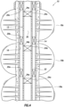
FIG. 6 , a representative enlarged scale cross-sectional view of anisolation tool 24 that can be used for any of theisolation tools 24a-c in thesystem 10 and method ofFIGS. 1-5 is illustrated. However, theisolation tool 24 may be used in other systems and methods in keeping with the principles of this disclosure. - In the
FIG. 6 example, theisolation tool 24 includes anouter housing 38 configured for connecting in thetubular string 12, so that theflow passage 30 extends longitudinally through the isolation tool. Theisolation tool 24 also includes aplug seat 40, apiston 42 and aclosure 44. - The
plug seat 40 is specially configured for sealingly engaging a plug 34 (seeFIG. 9 ) to block flow through thepassage 30. Theplug 34 can also be considered a component of theisolation tool 24, but the plug is not installed in the isolation tool until after the isolation tool is positioned in the well and it is desired to block flow through thepassage 30. - The
plug seat 40 contracts radially inward when it is longitudinally displaced by thepiston 42. When longitudinally displaced, a minimum internal diameter D of theplug seat 40 is reduced at two longitudinally spaced apart locations L, thereby retaining theplug 34 in the plug seat and providing for sealing engagement between the plug and the plug seat. - In the
FIG. 6 configuration, the internal diameter D of theplug seat 40 is approximately equal to a minimum internal diameter of a remainder of theisolation tool 24, and so the plug seat does not present a restriction to flow through the isolation tool. When theplug seat 40 is inwardly contracted, the internal diameter D is preferably only somewhat smaller than the minimum internal diameter of the remainder of theisolation tool 24, and so even when contracted the plug seat does not present a significant restriction to flow. - The
piston 42 is in annular form.Annular chambers piston 42 are at a same, relatively low (e.g., atmospheric), pressure and are dimensioned so that thepiston 42 is longitudinally pressure balanced in theFIG. 6 configuration (there is no net longitudinal force on the piston resulting from pressure applied to the piston). A shear pin, snap ring or other releasable retaining device may nevertheless be used to retain thepiston 42 in itsFIG. 6 position until it is desired for the piston to displace. - The
closure 44 is also in annular form, and is longitudinally pressure balanced. A shear pin, snap ring or other releasable retaining device may nevertheless be used to retain theclosure 44 in itsFIG. 6 position until it is desired for the closure to displace. - Upward displacement of the
closure 44 is used to expose thechamber 48 to well pressure, thereby unbalancing thepiston 42, and biasing the piston to displace downward and longitudinally displace theplug seat 40. This process is performed, as described more fully below, after theisolation tool 24 is installed in the well and theplug 34 is conveyed into theflow passage 30 and positioned in theplug seat 40. - Referring additionally now to
FIGS. 7 & 8 , enlarged scale perspective and cross-sectional views of theplug seat 40 are representatively illustrated. InFIG. 7 , it may be seen that a circumferential section of theplug seat 40 is removed, so that the plug seat can be readily compressed circumferentially to thereby reduce the diameter D (seeFIG. 6 ) . - The
plug seat 40 includes a generallytubular body 50 with a parallelogram-shapedcross-section seal 52 bonded or molded therein. A seal material 54 (such as, a resilient or elastomeric material) may also be bonded or coated on additional external and/or internal surfaces of thebody 50. - In some examples, metal-to-metal seals or other nonelastomeric materials may be used to seal between the
plug 34 and theplug seat 40, and/or between the plug seat and theouter housing 38. A wear-resistant coating could be bonded or coated on external and/or internal surfaces of thebody 50. - The
body 50 has a radially reducedportion 56 near its upper end. The radially reducedportion 56 is designed to contract radially inward when thebody 50 is longitudinally displaced. When radially contracted, theportion 56 will prevent theplug 34 from displacing upwardly out of theplug seat 40. - Another radially reduced
portion 58 is positioned at a bottom end of thebody 50. Inclined faces 60, 62 on the radially reducedportion 58 and on an adjacent portion of thebody 50 bias the bottom end of the body radially inward when thepiston 42 displaces the body downward. In theFIGS. 7 & 8 example, theportion 58 is provided with circumferentially spaced apart recesses 64 in the portion. - Referring additionally now to
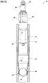
FIG. 9 , theisolation tool 24 is representatively illustrated after installation in the well, and after theplug 34 has been conveyed into the isolation tool. In this example, theplug 34 is in the form of a ball or sphere, but in other examples the plug could have a cylindrical shape or another shape. - The
plug 34 is attached to a shiftingtool 66 that is adapted to convey the plug into theisolation tool 24, but is otherwise conventional and of the type well known to those skilled in the art. The shiftingtool 66 can be conveyed into and through thepassage 30 by means of the conveyance 32 (seeFIG. 2 ). Theplug 34 in this example can be releasably attached to a lower end of the shiftingtool 66 by means of a shear screw (not visible inFIG. 9 ) or by another releasable retainer. - Shifting
dogs 68 of the shiftingtool 66 engage a complementarily shapedprofile 70 formed in theclosure 44, so that, by upwardly displacing the shifting tool, the closure can also be displaced upward. In a preferred manner of operation, the shiftingtool 66 with theplug 34 attached thereto is displaced downwardly through thepassage 30 in the isolation tool 24 (so that thedogs 68 are displaced below theprofile 70 and theplug 34 is displaced below the plug seat 40), and then the shifting tool is displaced upwardly in the isolation tool to engage thedogs 68 with theprofile 70 and then to upwardly displace theclosure 44 with the shifting tool. - Referring additionally now to
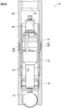
FIG. 10 , theisolation tool 24 is representatively illustrated after theclosure 44 has been upwardly displaced by the shiftingtool 66. The upward displacement of theclosure 44 has now exposed thechamber 48 to well pressure in thepassage 30. - Referring additionally now to
FIG. 11 , theisolation tool 24 is representatively illustrated after thepiston 42 has displaced downwardly. Thepiston 42 is biased to displace downward when it is no longer longitudinally pressure balanced (due to thechamber 48 being exposed to well pressure in the passage 30). - Note that the
plug seat 40 is longitudinally displaced downward by the downward displacement of thepiston 42. Theisolation tool 24 is dimensioned so that theplug 34 is positioned in theplug seat 40 when the plug seat is longitudinally displaced. - The radially reduced
portion 58 and theseal 52 are biased radially inward byinclined faces 72, 74 formed in thehousing 38. The inclined faces 72, 74 engage the inclined faces 60, 62 (seeFIGS. 7 & 8 ) formed on thebody 50 of theplug seat 40. When theplug seat 40 is displaced downward by thepiston 42, theportion 58 and the portion of theplug seat body 50 about theseal 52 are contracted radially inward. - Preferably, the radially reduced
portion 56 also contracts radially inward. By radially contracting theportion 56, upward displacement of theplug 34 out of theplug seat 40 is prevented. In this manner, the shiftingtool 66 can be retrieved from thepassage 30, leaving theplug 34 in the plug seat 40 (e.g., by shearing a shear screw or otherwise releasing the plug from the shifting tool). - Referring additionally now to
FIG. 12 , theisolation tool 24 is representatively illustrated after theplug 34 has been detached from the shiftingtool 66. The shiftingtool 66 can now be retrieved from thepassage 30. - In this configuration, the
plug 34 can sealingly engage theseal 52 in theplug seat 40. The seal material 54 (seeFIGS. 7 & 8 ) between the inclined faces 62, 72 can seal between theplug seat body 50 and thehousing 38. Increased pressure can now be applied to thepassage 30 above the plug 34 (for example, to fracture or otherwise treat a zone above the isolation tool 24), and the passage below the plug will be isolated from the increased pressure. - When it is no longer desired for the
plug 34 to block flow through thepassage 30, the plug can be dissolved, corroded, eroded, drilled or milled through, or otherwise degraded or dissipated, so that unobstructed flow is permitted through the passage. Only a minimal restriction to flow is then presented by the radially contractedplug seat 40 in theisolation tool 24. - The shifting
tool 66 with theplug 34 attached thereto can be conveyed into theisolation tool 24 by theconveyance 32. In some examples, setting theplug 34 in theisolation tool 24 could be combined with perforating a zone, so that only a single trip into the well accomplishes both operations. For example, the perforatinggun 28 could be connected between theconveyance 32 and the shiftingtool 66, as depicted inFIG. 2 . - It may now be fully appreciated that the above disclosure provides significant advances to the art of constructing and operating plugging tools in wells. In examples described above, the
isolation tool 24 can be used to conveniently, economically and effectively plug thepassage 30, without presenting a substantial restriction to flow through the isolation tool when the passage is again opened. - The above disclosure provides to the art a method of plugging a
flow passage 30 in a well. In one example, the method includes conveying aplug 34 into anisolation tool 24 in the well, and then contracting aplug seat 40 of theisolation tool 24. - The conveying step may include lowering the
plug 34 while the plug is attached to aconveyance 32. The conveying step may include attaching theplug 34 to a shiftingtool 66. The contracting step can comprise opening aclosure 44 of theisolation tool 24 with the shiftingtool 66. - The
plug seat 40 may be circumferentially discontinuous The contracting step can include deforming theplug seat 40 radially inward. - The contracting step may include a
piston 42 longitudinally displacing theplug seat 40. - The contracting step can include contracting the
plug seat 40 about theplug 34, thereby restricting displacement of the plug in both longitudinal directions through theflow passage 30. - Also provided to the art by the above disclosure is an
isolation tool 24 for plugging aflow passage 30 in a well. In one example, theisolation tool 24 comprises apiston 42 and a longitudinallydisplaceable plug seat 40. Theplug seat 40 longitudinally displaces in response to displacement of thepiston 42. - The
plug seat 40 may radially contract at longitudinally spaced apart locations L in response to displacement of thepiston 42. Theisolation tool 24 can also comprise aplug 34, at least a portion of the plug being positioned between the spaced apart locations L. - The
isolation tool 24 can include aclosure 44. Thepiston 42 may displace in response to displacement of theclosure 44 to an open position. - The
piston 42 may be longitudinally pressure balanced until displacement of theclosure 44 to the open position. - The
plug seat 40 may restrict displacement of aplug 34 in both longitudinal directions through theflow passage 30 in response to displacement of thepiston 42. - Also described above is a method of plugging a
flow passage 30, the method comprising: conveying aplug 34 into anisolation tool 24 in a well, and then longitudinally displacing aplug seat 40 of theisolation tool 24, thereby radially contracting theplug seat 40. - Although various examples have been described above, with each example having certain features, it should be understood that it is not necessary for a particular feature of one example to be used exclusively with that example. Instead, any of the features described above and/or depicted in the drawings can be combined with any of the examples, in addition to or in substitution for any of the other features of those examples. One example's features are not mutually exclusive to another example's features. Instead, the scope of this disclosure encompasses any combination of any of the features.
- Although each example described above includes a certain combination of features, it should be understood that it is not necessary for all features of an example to be used. Instead, any of the features described above can be used, without any other particular feature or features also being used.
- It should be understood that the various examples described herein may be utilized in various orientations, such as inclined, inverted, horizontal, vertical, etc., and in various configurations, without departing from the principles of this disclosure. The examples are described merely to illustrate useful applications of the principles of the disclosure.
- In the above description of the representative examples, directional terms (such as "above," "below," "upper," "lower," etc.) are used for convenience in referring to the accompanying drawings. However, it should be clearly understood that the scope of this disclosure is not limited to any particular directions described herein.
- Of course, a person skilled in the art would, upon a careful consideration of the above description of representative examples of the disclosure, readily appreciate that many modifications, additions, substitutions, deletions, and other changes may be made to the specific examples, and such changes are contemplated by the principles of this disclosure. For example, structures disclosed as being separately formed can, in other examples, be integrally formed and vice versa.
Claims (10)
- A method of plugging a flow passage (30) in a subterranean well (16), the method comprising:conveying a plug (34) into an isolation tool (24) in the well (16), wherein the conveying comprises lowering the plug (34) while the plug (34) is attached to a conveyance (32) ;wherein:the isolation tool comprises a closure (44), a piston (42) and a plug seat (40), a first isolation chamber (46), and a second isolation chamber (48); andthe piston (42) is longitudinally pressure balanced by the first and second isolation chambers (46, 48);characterized in that the method further comprises upwardly displacing the closure (44) of the isolation tool (24) to an open position, wherein:upwardly displacing the closure (44) causes the second isolation chamber (48) to be exposed to well pressure such that the piston (42) is no longer longitudinally pressure balanced; andthe piston (42) being no longer longitudinally pressure balanced causes the piston (42) to be displaced downward; wherein the displacement of the piston (42) causes downward longitudinal displacement of the plug seat (40), wherein displacement of the plug seat (40) causes contraction of a body (50) of the plug seat (40) of the isolation tool (24) about the plug (34).
- The method of claim 1, wherein contraction of the plug seat (40) of the isolation tool (24) about the plug (34) is radial contraction of the plug seat (40).
- The method of claim 1 or claim 2, wherein a shifting tool (66) is attached to the conveyance (32); preferably wherein the contracting comprises opening the closure (44) of the isolation tool (24) with the shifting tool (66).
- The method of claim 1 or 2, wherein the plug seat (40) is circumferentially discontinuous, and wherein the contracting comprises deforming the plug seat (40) radially inward.
- The method of claim 1 or 2, wherein the contracting comprises restricting displacement of the plug (34) in both longitudinal directions through the flow passage (30).
- An isolation tool (24) for use in the method of any preceding claim, the isolation tool (24) for plugging a flow passage (30) in a subterranean well (16), the isolation tool (24) comprising:a piston (42); anda longitudinally displaceable plug seat (40) comprising a body (50),characterized in that the plug seat (40) comprises a first radially reduced portion (56) towards the upper end of the body (50) and a second radially reduced portion (58) towards the bottom end of the body (50), wherein the plug seat (40) longitudinally displaces and radially contracts the radially reduced portions (56, 58) in response to displacement of the piston (42);further characterized in that the isolation tool (24) further comprises a closure (44), wherein the piston (42) displaces in response to displacement of the closure (44) to an open position, wherein displacement of the closure (44) in use causes an isolation chamber (48) of the isolation tool (24) to be exposed to well pressure such that the piston (42) is no longer longitudinally pressure balanced.
- The isolation tool (24) of claim 6, wherein the plug seat (40) is circumferentially discontinuous.
- The isolation tool (24) of claim 6, further comprising a plug (34), at least a portion of the plug (34) being positioned between the first and second radially reduced portions (56, 58).
- The isolation tool of claim 6, wherein the piston is longitudinally pressure balanced until displacement of the closure (44) to the open position.
- The isolation tool of claim 6, wherein the first radially reduced portion (56) of the plug seat (40) is arranged to restrict displacement of a plug (34) in the upward direction through the flow passage (30) in response to displacement of the piston (42).
Applications Claiming Priority (1)
| Application Number | Priority Date | Filing Date | Title |
|---|---|---|---|
| PCT/US2014/034275 WO2015160338A1 (en) | 2014-04-16 | 2014-04-16 | Plugging of a flow passage in a subterranean well |
Publications (3)
| Publication Number | Publication Date |
|---|---|
| EP3105409A1 EP3105409A1 (en) | 2016-12-21 |
| EP3105409A4 EP3105409A4 (en) | 2017-12-06 |
| EP3105409B1 true EP3105409B1 (en) | 2023-03-29 |
Family
ID=54321580
Family Applications (1)
| Application Number | Title | Priority Date | Filing Date |
|---|---|---|---|
| EP14889493.4A Active EP3105409B1 (en) | 2014-04-16 | 2014-04-16 | Plugging of a flow passage in a subterranean well |
Country Status (9)
| Country | Link |
|---|---|
| US (1) | US9790754B2 (en) |
| EP (1) | EP3105409B1 (en) |
| AR (1) | AR099966A1 (en) |
| AU (1) | AU2014391089B2 (en) |
| CA (1) | CA2941709C (en) |
| DK (1) | DK3105409T3 (en) |
| MX (1) | MX2016012794A (en) |
| PL (1) | PL3105409T3 (en) |
| WO (1) | WO2015160338A1 (en) |
Families Citing this family (3)
| Publication number | Priority date | Publication date | Assignee | Title |
|---|---|---|---|---|
| US10590758B2 (en) | 2015-11-12 | 2020-03-17 | Schlumberger Technology Corporation | Noise reduction for tubewave measurements |
| RU2709853C1 (en) | 2016-07-01 | 2019-12-23 | Шлюмберже Текнолоджи Б.В. | Method and system for detection in object of objects reflecting hydraulic signal |
| WO2020169910A1 (en) | 2019-02-18 | 2020-08-27 | Botbol Charles | Bucco-dental appliance for immobilizing the mandibular arch in protrusion, and method of manufacture |
Family Cites Families (14)
| Publication number | Priority date | Publication date | Assignee | Title |
|---|---|---|---|---|
| US4893678A (en) | 1988-06-08 | 1990-01-16 | Tam International | Multiple-set downhole tool and method |
| US6997263B2 (en) * | 2000-08-31 | 2006-02-14 | Halliburton Energy Services, Inc. | Multi zone isolation tool having fluid loss prevention capability and method for use of same |
| US6802372B2 (en) * | 2002-07-30 | 2004-10-12 | Weatherford/Lamb, Inc. | Apparatus for releasing a ball into a wellbore |
| US7322417B2 (en) * | 2004-12-14 | 2008-01-29 | Schlumberger Technology Corporation | Technique and apparatus for completing multiple zones |
| US8627890B2 (en) * | 2007-07-27 | 2014-01-14 | Weatherford/Lamb, Inc. | Rotating continuous flow sub |
| US7921922B2 (en) | 2008-08-05 | 2011-04-12 | PetroQuip Energy Services, LP | Formation saver sub and method |
| US9382790B2 (en) * | 2010-12-29 | 2016-07-05 | Schlumberger Technology Corporation | Method and apparatus for completing a multi-stage well |
| US8668006B2 (en) * | 2011-04-13 | 2014-03-11 | Baker Hughes Incorporated | Ball seat having ball support member |
| US8733450B2 (en) | 2011-05-03 | 2014-05-27 | Baker Hughes Incorporated | Tubular seating system and method of seating a plug |
| US8944171B2 (en) * | 2011-06-29 | 2015-02-03 | Schlumberger Technology Corporation | Method and apparatus for completing a multi-stage well |
| US8616276B2 (en) | 2011-07-11 | 2013-12-31 | Halliburton Energy Services, Inc. | Remotely activated downhole apparatus and methods |
| US20130048290A1 (en) | 2011-08-29 | 2013-02-28 | Halliburton Energy Services, Inc. | Injection of fluid into selected ones of multiple zones with well tools selectively responsive to magnetic patterns |
| US8739879B2 (en) | 2011-12-21 | 2014-06-03 | Baker Hughes Incorporated | Hydrostatically powered fracturing sliding sleeve |
| US9353598B2 (en) * | 2012-05-09 | 2016-05-31 | Utex Industries, Inc. | Seat assembly with counter for isolating fracture zones in a well |
-
2014
- 2014-04-16 US US14/434,538 patent/US9790754B2/en active Active
- 2014-04-16 WO PCT/US2014/034275 patent/WO2015160338A1/en active Application Filing
- 2014-04-16 PL PL14889493.4T patent/PL3105409T3/en unknown
- 2014-04-16 CA CA2941709A patent/CA2941709C/en active Active
- 2014-04-16 EP EP14889493.4A patent/EP3105409B1/en active Active
- 2014-04-16 MX MX2016012794A patent/MX2016012794A/en unknown
- 2014-04-16 AU AU2014391089A patent/AU2014391089B2/en active Active
- 2014-04-16 DK DK14889493.4T patent/DK3105409T3/en active
-
2015
- 2015-04-06 AR ARP150101033A patent/AR099966A1/en active IP Right Grant
Also Published As
| Publication number | Publication date |
|---|---|
| US20150300115A1 (en) | 2015-10-22 |
| US9790754B2 (en) | 2017-10-17 |
| MX2016012794A (en) | 2017-04-25 |
| AU2014391089A1 (en) | 2016-09-01 |
| PL3105409T3 (en) | 2023-12-04 |
| CA2941709A1 (en) | 2015-10-22 |
| EP3105409A4 (en) | 2017-12-06 |
| CA2941709C (en) | 2018-08-14 |
| DK3105409T3 (en) | 2023-06-19 |
| EP3105409A1 (en) | 2016-12-21 |
| AR099966A1 (en) | 2016-08-31 |
| AU2014391089B2 (en) | 2017-09-14 |
| WO2015160338A1 (en) | 2015-10-22 |
Similar Documents
| Publication | Publication Date | Title |
|---|---|---|
| US8662178B2 (en) | Responsively activated wellbore stimulation assemblies and methods of using the same | |
| US10113388B2 (en) | Apparatus and method for providing wellbore isolation | |
| US10301907B2 (en) | Setting tool with pressure shock absorber | |
| US10907445B2 (en) | Autofill and circulation assembly and method of using the same | |
| EP3458676A1 (en) | Top-down squeeze system and method | |
| EP3354842B1 (en) | Ball valve safety plug | |
| US20220127931A1 (en) | Shifting tool and associated methods for operating downhole valves | |
| US20140083715A1 (en) | Remotely operated production valve and method | |
| EP3105409B1 (en) | Plugging of a flow passage in a subterranean well | |
| US9683416B2 (en) | System and methods for recovering hydrocarbons | |
| US11125052B2 (en) | Frac valve | |
| US11280160B2 (en) | Multi-zone hydraulic stimulation system | |
| US20150114651A1 (en) | Downhole fracturing system and technique |
Legal Events
| Date | Code | Title | Description |
|---|---|---|---|
| STAA | Information on the status of an ep patent application or granted ep patent |
Free format text: STATUS: THE INTERNATIONAL PUBLICATION HAS BEEN MADE |
|
| PUAI | Public reference made under article 153(3) epc to a published international application that has entered the european phase |
Free format text: ORIGINAL CODE: 0009012 |
|
| STAA | Information on the status of an ep patent application or granted ep patent |
Free format text: STATUS: REQUEST FOR EXAMINATION WAS MADE |
|
| 17P | Request for examination filed |
Effective date: 20160915 |
|
| AK | Designated contracting states |
Kind code of ref document: A1 Designated state(s): AL AT BE BG CH CY CZ DE DK EE ES FI FR GB GR HR HU IE IS IT LI LT LU LV MC MK MT NL NO PL PT RO RS SE SI SK SM TR |
|
| AX | Request for extension of the european patent |
Extension state: BA ME |
|
| DAX | Request for extension of the european patent (deleted) | ||
| A4 | Supplementary search report drawn up and despatched |
Effective date: 20171107 |
|
| RIC1 | Information provided on ipc code assigned before grant |
Ipc: E21B 23/02 20060101AFI20171030BHEP Ipc: E21B 33/12 20060101ALI20171030BHEP Ipc: E21B 43/14 20060101ALI20171030BHEP |
|
| STAA | Information on the status of an ep patent application or granted ep patent |
Free format text: STATUS: EXAMINATION IS IN PROGRESS |
|
| 17Q | First examination report despatched |
Effective date: 20210610 |
|
| STAA | Information on the status of an ep patent application or granted ep patent |
Free format text: STATUS: EXAMINATION IS IN PROGRESS |
|
| GRAP | Despatch of communication of intention to grant a patent |
Free format text: ORIGINAL CODE: EPIDOSNIGR1 |
|
| STAA | Information on the status of an ep patent application or granted ep patent |
Free format text: STATUS: GRANT OF PATENT IS INTENDED |
|
| INTG | Intention to grant announced |
Effective date: 20221021 |
|
| GRAS | Grant fee paid |
Free format text: ORIGINAL CODE: EPIDOSNIGR3 |
|
| GRAA | (expected) grant |
Free format text: ORIGINAL CODE: 0009210 |
|
| STAA | Information on the status of an ep patent application or granted ep patent |
Free format text: STATUS: THE PATENT HAS BEEN GRANTED |
|
| AK | Designated contracting states |
Kind code of ref document: B1 Designated state(s): AL AT BE BG CH CY CZ DE DK EE ES FI FR GB GR HR HU IE IS IT LI LT LU LV MC MK MT NL NO PL PT RO RS SE SI SK SM TR |
|
| REG | Reference to a national code |
Ref country code: GB Ref legal event code: FG4D |
|
| REG | Reference to a national code |
Ref country code: CH Ref legal event code: EP |
|
| REG | Reference to a national code |
Ref country code: DE Ref legal event code: R096 Ref document number: 602014086573 Country of ref document: DE |
|
| REG | Reference to a national code |
Ref country code: AT Ref legal event code: REF Ref document number: 1556773 Country of ref document: AT Kind code of ref document: T Effective date: 20230415 |
|
| REG | Reference to a national code |
Ref country code: IE Ref legal event code: FG4D |
|
| REG | Reference to a national code |
Ref country code: DK Ref legal event code: T3 Effective date: 20230616 |
|
| REG | Reference to a national code |
Ref country code: NO Ref legal event code: T2 Effective date: 20230329 Ref country code: LT Ref legal event code: MG9D |
|
| P01 | Opt-out of the competence of the unified patent court (upc) registered |
Effective date: 20230530 |
|
| PG25 | Lapsed in a contracting state [announced via postgrant information from national office to epo] |
Ref country code: RS Free format text: LAPSE BECAUSE OF FAILURE TO SUBMIT A TRANSLATION OF THE DESCRIPTION OR TO PAY THE FEE WITHIN THE PRESCRIBED TIME-LIMIT Effective date: 20230329 Ref country code: LV Free format text: LAPSE BECAUSE OF FAILURE TO SUBMIT A TRANSLATION OF THE DESCRIPTION OR TO PAY THE FEE WITHIN THE PRESCRIBED TIME-LIMIT Effective date: 20230329 Ref country code: LT Free format text: LAPSE BECAUSE OF FAILURE TO SUBMIT A TRANSLATION OF THE DESCRIPTION OR TO PAY THE FEE WITHIN THE PRESCRIBED TIME-LIMIT Effective date: 20230329 Ref country code: HR Free format text: LAPSE BECAUSE OF FAILURE TO SUBMIT A TRANSLATION OF THE DESCRIPTION OR TO PAY THE FEE WITHIN THE PRESCRIBED TIME-LIMIT Effective date: 20230329 |
|
| PGFP | Annual fee paid to national office [announced via postgrant information from national office to epo] |
Ref country code: RO Payment date: 20230418 Year of fee payment: 10 Ref country code: NO Payment date: 20230420 Year of fee payment: 10 Ref country code: IT Payment date: 20230620 Year of fee payment: 10 Ref country code: DK Payment date: 20230621 Year of fee payment: 10 |
|
| REG | Reference to a national code |
Ref country code: NL Ref legal event code: MP Effective date: 20230329 |
|
| REG | Reference to a national code |
Ref country code: AT Ref legal event code: MK05 Ref document number: 1556773 Country of ref document: AT Kind code of ref document: T Effective date: 20230329 |
|
| PG25 | Lapsed in a contracting state [announced via postgrant information from national office to epo] |
Ref country code: SE Free format text: LAPSE BECAUSE OF FAILURE TO SUBMIT A TRANSLATION OF THE DESCRIPTION OR TO PAY THE FEE WITHIN THE PRESCRIBED TIME-LIMIT Effective date: 20230329 Ref country code: NL Free format text: LAPSE BECAUSE OF FAILURE TO SUBMIT A TRANSLATION OF THE DESCRIPTION OR TO PAY THE FEE WITHIN THE PRESCRIBED TIME-LIMIT Effective date: 20230329 Ref country code: GR Free format text: LAPSE BECAUSE OF FAILURE TO SUBMIT A TRANSLATION OF THE DESCRIPTION OR TO PAY THE FEE WITHIN THE PRESCRIBED TIME-LIMIT Effective date: 20230630 Ref country code: FI Free format text: LAPSE BECAUSE OF FAILURE TO SUBMIT A TRANSLATION OF THE DESCRIPTION OR TO PAY THE FEE WITHIN THE PRESCRIBED TIME-LIMIT Effective date: 20230329 |
|
| PG25 | Lapsed in a contracting state [announced via postgrant information from national office to epo] |
Ref country code: SM Free format text: LAPSE BECAUSE OF FAILURE TO SUBMIT A TRANSLATION OF THE DESCRIPTION OR TO PAY THE FEE WITHIN THE PRESCRIBED TIME-LIMIT Effective date: 20230329 Ref country code: PT Free format text: LAPSE BECAUSE OF FAILURE TO SUBMIT A TRANSLATION OF THE DESCRIPTION OR TO PAY THE FEE WITHIN THE PRESCRIBED TIME-LIMIT Effective date: 20230731 Ref country code: ES Free format text: LAPSE BECAUSE OF FAILURE TO SUBMIT A TRANSLATION OF THE DESCRIPTION OR TO PAY THE FEE WITHIN THE PRESCRIBED TIME-LIMIT Effective date: 20230329 Ref country code: EE Free format text: LAPSE BECAUSE OF FAILURE TO SUBMIT A TRANSLATION OF THE DESCRIPTION OR TO PAY THE FEE WITHIN THE PRESCRIBED TIME-LIMIT Effective date: 20230329 Ref country code: AT Free format text: LAPSE BECAUSE OF FAILURE TO SUBMIT A TRANSLATION OF THE DESCRIPTION OR TO PAY THE FEE WITHIN THE PRESCRIBED TIME-LIMIT Effective date: 20230329 |
|
| PGFP | Annual fee paid to national office [announced via postgrant information from national office to epo] |
Ref country code: GB Payment date: 20230403 Year of fee payment: 10 |
|
| REG | Reference to a national code |
Ref country code: DE Ref legal event code: R119 Ref document number: 602014086573 Country of ref document: DE |
|
| PG25 | Lapsed in a contracting state [announced via postgrant information from national office to epo] |
Ref country code: SK Free format text: LAPSE BECAUSE OF FAILURE TO SUBMIT A TRANSLATION OF THE DESCRIPTION OR TO PAY THE FEE WITHIN THE PRESCRIBED TIME-LIMIT Effective date: 20230329 Ref country code: IS Free format text: LAPSE BECAUSE OF FAILURE TO SUBMIT A TRANSLATION OF THE DESCRIPTION OR TO PAY THE FEE WITHIN THE PRESCRIBED TIME-LIMIT Effective date: 20230729 |
|
| REG | Reference to a national code |
Ref country code: CH Ref legal event code: PL |
|
| PG25 | Lapsed in a contracting state [announced via postgrant information from national office to epo] |
Ref country code: LU Free format text: LAPSE BECAUSE OF NON-PAYMENT OF DUE FEES Effective date: 20230416 |
|
| REG | Reference to a national code |
Ref country code: BE Ref legal event code: MM Effective date: 20230430 |
|
| PG25 | Lapsed in a contracting state [announced via postgrant information from national office to epo] |
Ref country code: MC Free format text: LAPSE BECAUSE OF FAILURE TO SUBMIT A TRANSLATION OF THE DESCRIPTION OR TO PAY THE FEE WITHIN THE PRESCRIBED TIME-LIMIT Effective date: 20230329 |
|
| PG25 | Lapsed in a contracting state [announced via postgrant information from national office to epo] |
Ref country code: MC Free format text: LAPSE BECAUSE OF FAILURE TO SUBMIT A TRANSLATION OF THE DESCRIPTION OR TO PAY THE FEE WITHIN THE PRESCRIBED TIME-LIMIT Effective date: 20230329 Ref country code: LI Free format text: LAPSE BECAUSE OF NON-PAYMENT OF DUE FEES Effective date: 20230430 Ref country code: DE Free format text: LAPSE BECAUSE OF NON-PAYMENT OF DUE FEES Effective date: 20231103 Ref country code: CZ Free format text: LAPSE BECAUSE OF FAILURE TO SUBMIT A TRANSLATION OF THE DESCRIPTION OR TO PAY THE FEE WITHIN THE PRESCRIBED TIME-LIMIT Effective date: 20230329 Ref country code: CH Free format text: LAPSE BECAUSE OF NON-PAYMENT OF DUE FEES Effective date: 20230430 |
|
| PLBE | No opposition filed within time limit |
Free format text: ORIGINAL CODE: 0009261 |
|
| STAA | Information on the status of an ep patent application or granted ep patent |
Free format text: STATUS: NO OPPOSITION FILED WITHIN TIME LIMIT |
|
| REG | Reference to a national code |
Ref country code: IE Ref legal event code: MM4A |
|
| PG25 | Lapsed in a contracting state [announced via postgrant information from national office to epo] |
Ref country code: BE Free format text: LAPSE BECAUSE OF NON-PAYMENT OF DUE FEES Effective date: 20230430 |
|
| PGFP | Annual fee paid to national office [announced via postgrant information from national office to epo] |
Ref country code: PL Payment date: 20230525 Year of fee payment: 10 |
|
| 26N | No opposition filed |
Effective date: 20240103 |
|
| PG25 | Lapsed in a contracting state [announced via postgrant information from national office to epo] |
Ref country code: IE Free format text: LAPSE BECAUSE OF NON-PAYMENT OF DUE FEES Effective date: 20230416 |
|
| PG25 | Lapsed in a contracting state [announced via postgrant information from national office to epo] |
Ref country code: IE Free format text: LAPSE BECAUSE OF NON-PAYMENT OF DUE FEES Effective date: 20230416 |
|
| PGFP | Annual fee paid to national office [announced via postgrant information from national office to epo] |
Ref country code: GB Payment date: 20240201 Year of fee payment: 11 |
|
| PG25 | Lapsed in a contracting state [announced via postgrant information from national office to epo] |
Ref country code: SI Free format text: LAPSE BECAUSE OF FAILURE TO SUBMIT A TRANSLATION OF THE DESCRIPTION OR TO PAY THE FEE WITHIN THE PRESCRIBED TIME-LIMIT Effective date: 20230329 |