EP3105147B1 - Valve de distribution comprenant une valve de dosage - Google Patents
Valve de distribution comprenant une valve de dosage Download PDFInfo
- Publication number
- EP3105147B1 EP3105147B1 EP15748520.2A EP15748520A EP3105147B1 EP 3105147 B1 EP3105147 B1 EP 3105147B1 EP 15748520 A EP15748520 A EP 15748520A EP 3105147 B1 EP3105147 B1 EP 3105147B1
- Authority
- EP
- European Patent Office
- Prior art keywords
- valve
- metering
- product
- dispensing
- dispensed
- Prior art date
- Legal status (The legal status is an assumption and is not a legal conclusion. Google has not performed a legal analysis and makes no representation as to the accuracy of the status listed.)
- Active
Links
- 238000007789 sealing Methods 0.000 claims description 167
- 239000000443 aerosol Substances 0.000 claims description 25
- 230000008878 coupling Effects 0.000 claims description 21
- 238000010168 coupling process Methods 0.000 claims description 21
- 238000005859 coupling reaction Methods 0.000 claims description 21
- 230000037452 priming Effects 0.000 claims description 16
- 238000004891 communication Methods 0.000 claims description 13
- 230000005484 gravity Effects 0.000 claims description 8
- 238000000034 method Methods 0.000 claims description 7
- 230000000881 depressing effect Effects 0.000 claims description 6
- 239000012530 fluid Substances 0.000 claims description 6
- 230000000717 retained effect Effects 0.000 claims description 3
- 239000003570 air Substances 0.000 description 17
- 230000000994 depressogenic effect Effects 0.000 description 12
- 239000007789 gas Substances 0.000 description 11
- 239000003380 propellant Substances 0.000 description 7
- 239000011346 highly viscous material Substances 0.000 description 5
- 239000007788 liquid Substances 0.000 description 5
- CURLTUGMZLYLDI-UHFFFAOYSA-N Carbon dioxide Chemical compound O=C=O CURLTUGMZLYLDI-UHFFFAOYSA-N 0.000 description 4
- 238000005516 engineering process Methods 0.000 description 3
- 238000005429 filling process Methods 0.000 description 3
- 239000000463 material Substances 0.000 description 3
- 230000007246 mechanism Effects 0.000 description 3
- 239000003595 mist Substances 0.000 description 3
- 230000008569 process Effects 0.000 description 3
- 239000007921 spray Substances 0.000 description 3
- IJGRMHOSHXDMSA-UHFFFAOYSA-N Atomic nitrogen Chemical compound N#N IJGRMHOSHXDMSA-UHFFFAOYSA-N 0.000 description 2
- 230000000712 assembly Effects 0.000 description 2
- 238000000429 assembly Methods 0.000 description 2
- 229910002092 carbon dioxide Inorganic materials 0.000 description 2
- 239000001569 carbon dioxide Substances 0.000 description 2
- 238000002788 crimping Methods 0.000 description 2
- 239000000499 gel Substances 0.000 description 2
- 238000004519 manufacturing process Methods 0.000 description 2
- JCXJVPUVTGWSNB-UHFFFAOYSA-N nitrogen dioxide Inorganic materials O=[N]=O JCXJVPUVTGWSNB-UHFFFAOYSA-N 0.000 description 2
- 239000000126 substance Substances 0.000 description 2
- 229940034610 toothpaste Drugs 0.000 description 2
- 239000000606 toothpaste Substances 0.000 description 2
- 235000013361 beverage Nutrition 0.000 description 1
- 230000000903 blocking effect Effects 0.000 description 1
- 239000000919 ceramic Substances 0.000 description 1
- 239000000084 colloidal system Substances 0.000 description 1
- 239000006071 cream Substances 0.000 description 1
- 238000007599 discharging Methods 0.000 description 1
- 238000009826 distribution Methods 0.000 description 1
- 230000000694 effects Effects 0.000 description 1
- 239000006260 foam Substances 0.000 description 1
- 238000009434 installation Methods 0.000 description 1
- 239000002184 metal Substances 0.000 description 1
- 239000004033 plastic Substances 0.000 description 1
- 239000002861 polymer material Substances 0.000 description 1
- 239000004810 polytetrafluoroethylene Substances 0.000 description 1
- 229920001343 polytetrafluoroethylene Polymers 0.000 description 1
- 230000007704 transition Effects 0.000 description 1
- 239000011345 viscous material Substances 0.000 description 1
Images


Classifications
-
- B—PERFORMING OPERATIONS; TRANSPORTING
- B65—CONVEYING; PACKING; STORING; HANDLING THIN OR FILAMENTARY MATERIAL
- B65D—CONTAINERS FOR STORAGE OR TRANSPORT OF ARTICLES OR MATERIALS, e.g. BAGS, BARRELS, BOTTLES, BOXES, CANS, CARTONS, CRATES, DRUMS, JARS, TANKS, HOPPERS, FORWARDING CONTAINERS; ACCESSORIES, CLOSURES, OR FITTINGS THEREFOR; PACKAGING ELEMENTS; PACKAGES
- B65D83/00—Containers or packages with special means for dispensing contents
- B65D83/14—Containers or packages with special means for dispensing contents for delivery of liquid or semi-liquid contents by internal gaseous pressure, i.e. aerosol containers comprising propellant for a product delivered by a propellant
- B65D83/60—Contents and propellant separated
- B65D83/62—Contents and propellant separated by membrane, bag, or the like
-
- B—PERFORMING OPERATIONS; TRANSPORTING
- B65—CONVEYING; PACKING; STORING; HANDLING THIN OR FILAMENTARY MATERIAL
- B65D—CONTAINERS FOR STORAGE OR TRANSPORT OF ARTICLES OR MATERIALS, e.g. BAGS, BARRELS, BOTTLES, BOXES, CANS, CARTONS, CRATES, DRUMS, JARS, TANKS, HOPPERS, FORWARDING CONTAINERS; ACCESSORIES, CLOSURES, OR FITTINGS THEREFOR; PACKAGING ELEMENTS; PACKAGES
- B65D83/00—Containers or packages with special means for dispensing contents
- B65D83/14—Containers or packages with special means for dispensing contents for delivery of liquid or semi-liquid contents by internal gaseous pressure, i.e. aerosol containers comprising propellant for a product delivered by a propellant
- B65D83/44—Valves specially adapted therefor; Regulating devices
- B65D83/52—Valves specially adapted therefor; Regulating devices for metering
- B65D83/54—Metering valves ; Metering valve assemblies
- B65D83/546—Metering valves ; Metering valve assemblies the metering occurring at least partially in the actuating means
-
- B—PERFORMING OPERATIONS; TRANSPORTING
- B65—CONVEYING; PACKING; STORING; HANDLING THIN OR FILAMENTARY MATERIAL
- B65D—CONTAINERS FOR STORAGE OR TRANSPORT OF ARTICLES OR MATERIALS, e.g. BAGS, BARRELS, BOTTLES, BOXES, CANS, CARTONS, CRATES, DRUMS, JARS, TANKS, HOPPERS, FORWARDING CONTAINERS; ACCESSORIES, CLOSURES, OR FITTINGS THEREFOR; PACKAGING ELEMENTS; PACKAGES
- B65D83/00—Containers or packages with special means for dispensing contents
- B65D83/14—Containers or packages with special means for dispensing contents for delivery of liquid or semi-liquid contents by internal gaseous pressure, i.e. aerosol containers comprising propellant for a product delivered by a propellant
- B65D83/38—Details of the container body
Definitions
- the present invention relates to a metering valve that dispenses a predetermined quantity of material from a container, under a dispensing pressure of an aerosol or compressed gas, that is simple in structure and readily manufactured.
- the present invention further relates to a high flow valve used in conjunction with a compressed gas, an aerosol or in bag-on-valve applications, and particularly to a valve having a housing that is supported by a mounting cup for a product container or can, and communicates with a product or product containment bag inside the can, where the radial opening of the valve is positioned closer to a lower seal of the valve stem rather than an upper seal or mounting cup gasket facilitating an increased flow rate for dispensing the product from the container and valve.
- the valve stem serves as a metering chamber with a metering device within the valve stem that seals the valve stem from the container in a pre-dispensing position and seals the exit orifice of the chamber after dispensing from the valve stem metering chamber the predetermined quantity of material.
- Standard aerosol valve and gasket assemblies for dispensing pressurized product from a container have an inherent structural problem which limits the flow rate of product through the valve stem and out of the container.
- the gasket which seals the conventional radial opening of the spring biased valve in the valve housing of conventional aerosol valves also seals the valve stem with the mounting cup of the container, limiting the diameter of the opening relative to the valve stem extending through the gasket.
- the valve stem is provided with both an axial and a radial opening for dispensing product from the container.
- valve stem When the valve stem is depressed inward or pushed down by a user against a spring bias, the radial opening, which is initially blocked by the gasket, is moved into fluid communication with the product contained in the container so that this product is then permitted to flow through the radial opening and out the valve stem and be discharged or dispensed into the environment. Once the user releases the valve stem, the valve stem is automatically returned back into its sealed, closed position with the mounting cup gasket again blocking the radial opening.
- the FR 1 598 257 A relates to the fractional distribution of substances under pressure as well as a method for dispensing. Furthermore, it also relates to a metering dispenser for dispensing.
- the structural problem is two-fold; first, the diameter of the radial opening formed in the side all of the valve stem must be smaller than the thickness of the gasket so that the radial opening is adequately covered and sealed in the closed valve position, otherwise there is a substantial risk of the product leaking or flowing into the radial opening and inadvertently able to escape the product contained even when the valve is closed.
- the thickness of a conventional gasket is typically in the range of 1.02 mm - 1.52 mm (0.04 - 0.06 inches), so that the diameter of the radial opening must be substantially within this range or slightly smaller. This along with tolerances necessary to ensure complete closure of the valve limits the size of the radial opening.
- valve stem openings create the same or similar structural issues.
- Collapsible and highly flexible product bags or pouches have become common in different industries for containing a variety of food, beverages, personal care or household care or other similar products.
- product bags can be used alone to allow a user to manually squeeze and dispense a product from the bag or the product bag may be utilized in combination with a pressurized can and product, for example an aerosol.
- Such product bags and valves contained in and used with aerosol cans are generally referred to in the aerosol dispensing industry as bag-on-valve (BOV) technology.
- BOV bag-on-valve
- These product bags, valves and cans may be designed to receive and dispense a desired product in either a liquid or semi-liquid form which has a consistency so as to be able to be expelled from the valve or outlet by the user when desired.
- Bag-on-valve technology is known to utilize a product dispenser, such as a can, which has an empty collapsible product bag inserted therein prior to filling of the bag with the desired product to be dispensed.
- the bag is initially flat and rolled up to form a smaller diameter so as to facilitate axial installation of the bag inside the can with a portion of a filling/dispensing valve communicating with an interior space of the product bag.
- the product bag is filled with the desired product to be dispensed.
- a desired product to be dispensed is inserted into the product bag via the two-way valve by conventional filling mechanisms.
- the product bag expands inside the can.
- the can is supplied with a pressurized gas, an aerosol or a compressed gas, in order to assist with squeezing the bag to expel the product contents thereof as is well known in the art.
- a pressurized gas an aerosol or a compressed gas
- the valve is a key component, which led to the design of multiple valve configurations for a variety of different applications.
- valve housing engages with a mounting cup of a can, attaches to a bag that holds the product to be dispensed, and provides the framework for the valve stem.
- the valve stem usually interacts with the interior of the valve housing through the use of a spring.
- the spring allows the valve stem to move relative to the valve housing to open and close the valve.
- product to be dispensed flows from the product bag, to and through the valve housing, then through a passage in the valve stem, and finally the product is discharged, via a discharge nozzle of some sort, into the environment.
- the passage is normally limited in size and shape based on the sealing of the passage by the upper gasket that is used to seal the valve housing to the mounting cup.
- the various product contents include, for example, liquids, creams, foams, gels, aerosols, colloids, and various other substances.
- the present invention addresses the required increased flow rate necessary in some bag-on-valve applications, in some aerosol applications, however, the bag- on-valve containers may not be feasible due to volume constraints of the container and cost considerations, even though it may be undesirable to mix the propellant gas with the product material. In these instances, immiscible gases, such as nitrogen or carbon dioxide, may be preferred.
- the present invention provides for liquefied propellants or compressed gas, such as air, nitrogen or carbon dioxide, to be used and further may provide metered doses of product to be dispensed as required in some aerosol applications.
- the present invention is directed to a valve used in both conventional and bag-on-valve aerosol container applications that allows a high flow rate of various products, especially viscous substances.
- the valve includes a valve housing, a valve stem, and a spring or other biasing element that permits the valve stem to move relative to the valve housing.
- the valve stem is substantially hollow to allow the flow of product to the bag, during the filling process, and to the product to be dispensed from the bag during use.
- the bag is attached to the valve housing in a conventional fashion. There is a radial bore or bores and a seal near the bottom of the valve stem that dictate the passage and flow rate of pressurized product to be dispensed between the product container and the environment.
- the radial bore at the bottom or lower portion of the valve stem provides for flow directly from the product reservoir, defined by the bag, to the valve stem passage when a lower seal on the valve is opened.
- the valve stem passage is sealed by the lower seal or ring which is a separate sealing gasket or ring from the upper gasket.
- the lower seal may be located anywhere along the valve stem below the upper gasket and preferably at the bottom or lower portion of the valve stem facilitating communication to the product reservoir.
- the upper portion of the valve stem and upper gasket both refer to the end of the valve stem and the gasket adjacent the orifice in the mounting cup.
- the lower portion of the valve stem and the lower gasket or ring are spaced from and located axially below the upper portion and generally more interior of the container so that product ejected from the container when the valve is actuated travels from the lower portion of the valve stem past the lower gasket or ring up through the upper portion of the valve stem and out of the valve.
- a lower sealing gasket or ring allows one or more larger diameter bore(s) to be radially formed in the lower portion of the valve stem without compromising the integrity of the valve stem itself.
- the bore shape and larger size can be selected to facilitate a high volume flow rate for highly viscous substances.
- a triangular or polygonal shape bore could provide a variable flow rate into and through the valve stem to ensure that highly viscous materials are dispensed at a desired flow rate, depending on an actuation pressure of a user. It is, therefore, an object of the present invention to overcome the above noted issues and produce a valve for both conventional aerosol valve and bag-on-valve systems which facilitates a high volume flow rate for liquids and semi-liquids of different viscosities.
- a metering device such as a metal, ceramic or plastic ball is positioned within the valve stem to provide for dispensing a metered dose of product to be dispensed.
- a metering device such as a metal, ceramic or plastic ball is positioned within the valve stem to provide for dispensing a metered dose of product to be dispensed.
- the use of a metering device within a metering chamber is well known, with many aerosol valve designs of the prior art showing elaborate, costly and difficult to manufacture mechanisms having one or more mechanical springs, plungers, and other contrivances within the metering chamber to control the movement and positioning of the metering device. What is not shown in the prior art is the placement of the metering device within the valve stem.
- the location of the sealing ring at the base of the valve stem provides for radial inlet passages to be positioned below a lower sealing rim that using the metering device seals the pre-determined quantity of product within the valve stem from the product within the container.
- a propellant such as a compressed gas within the container can be used because the propellant acts directly on the metering device to force the metering device through the valve stem and dispense the predetermined quantity of product to be dispensed.
- the propellant acts directly on the metering device to dispense the pre-determined quantity that is defined by the volume of the valve stem.
- This volume may therefore be adjusted by changing the length and diameter of the valve stem, which as a single piece may be interchangeable and be easily replaced in the valve housing to provide for larger or smaller required dosage volumes for specific products and applications.
- the valve stem is initially filled with product to be dispensed through a priming actuation by fully or partially compressing the valve stem.
- the propellant which may be a compressed gas, forces the ball as a metering device off of a lower sealing rim to travel up and through the valve stem thereby dispensing the quantity of product to be dispensed within the valve stem.
- the ball engages an upper sealing rim at the outlet orifice of the valve stem to seal and prevent further product from being dispensed to the inlet passage of the actuator and nozzle.
- valve stem as the metering chamber is therefore filled with the pre-determined quantity of product for dispensing another metered dose.
- a small conduit may be provided at the upper sealing rim. The conduit provides communication between the valve stem and air external to the aerosol container in order to provide a pressure differential on each side of ball to release the ball from the upper sealing position after the valve is released. It is therefore an object of the invention to provide for a metering device within the valve stem to simplify the assembly and cost of a metering valve.
- Another object of the present invention is to provide a two-way valve which permits a substantial increase in the speed of filling a product container or bag, especially in the context of highly viscous substances.
- the present invention relates to a dispensing valve according to claim 1.
- the present invention also relates to a method of dispensing a product to be dispensed from a dispensing valve according to claim 15.
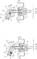
- FIG. 1 illustrates a side view of an embodiment not forming part of the present invention depicting the valve 1 in conjunction with the mounting cup 5 for a product containing can or container (not shown) in a bag-on-valve system.
- the valve stem 7 is arranged parallel to and extends out of the valve housing 3 and through the mounting cup 5.
- the valve housing 3 has multiple sections or portions that correspond to different functions for the bag-on-valve application.
- a top portion of the valve housing is engaged with the mounting cup, by crimping, to secure the valve housing 3 to the mounting cup 5.
- the middle portion of the valve housing 3 accommodates a spring cavity 9, which generally houses a spring for controlling dynamic movement between the valve stem 7 and the valve housing 3.
- the spring normally biases the valve stem 7 away from a bottom portion 11 of the valve housing 3 into a closed position which prevents the discharge of product from the container.
- the bottom portion 11 of the valve housing 3 either engages with a dip tube, or as described in this embodiment, with a product bag in the case of a bag-on-valve.
- a top edge of the product bag (not shown) engages and seals with the bottom portion 11, along a fitment 13, and the valve 1 is utilized to dispense the contents or product to be dispensed from the bag.
- the valve 1 can be a two-way valve which would allow for product to be dispensed to be inserted into the bag during a filling process as well as dispensed therefrom.
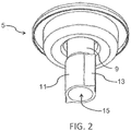
- the bottom portion 1 1 is better illustrated in the perspective view of FIG. 2 .
- the fitment 13 on the bottom portion 11 assists in the sealing engagement between the base or bottom portion of the valve housing 3 and the product bag B is more fully described in U.S. Patent Application No. 12/667,423 .
- This view also shows the entrance to cavity 15 of the valve housing 3 that receives the product to be dispensed from the bag when a user manipulates or operates the valve into an open position to dispense the product.
- the entrance to cavity 15 may or may not communicate with a dip tube 16 which extends downward info the lower edges and corners of the bag to facilitate complete product dispensing.
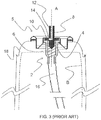
- FIG. 3 A cross-sectional view of a conventional valve 2, according to the prior art, is shown FIG. 3 .
- the valve 2 is secured to a mounting cup 5 and has a valve stem 8, a valve housing 4, a valve spring 6 and valve gasket 10.
- the valve 2 is actuated by depressing the valve stem 8 along axis A to a point below the seal of the gasket 10, against a restoring force supplied by the valve spring 6, so that product to be dispensed may commence flowing from the bag B through the product passage 12 and out from the valve container.
- the gasket 10 also seals the valve housing 4 to the mounting cup 5 to prevent leakage therebetween.
- the bag B is within the aerosol container 18.
- the spring 6 normally biases the valve 2 in a normally closed position, as shown, with the opening to the product passage 14 being sealed by and against the gasket 10.
- the product to be dispensed flows along the valve housing 4, up and around the valve stem 8 and into the product passage 12.
- the valve 2 may or may not include a dip tube 16 to assist with dispensing product from the bag B.
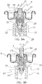
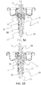
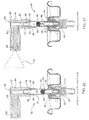
- FIGS. 3A and 3B are cross-sectional views of the bag-on-valve embodiment which show the valve housing 3 engaged with the mounting cup 5.
- An inner gasket 29 is used to form a seal between the valve housing cavity 15, the valve stem 7 and the mounting cup 5.
- the valve stem 7 extends through the mounting cup 5 and out of the valve housing 3 and is axially biased into a closed position by spring 33.
- the valve stem 7 is provided with an end sealing portion 23 and a product entrance orifice(s) 21 located adjacent the end sealing portion 23 of the valve stem 7,
- the valve stem 7 is axially disposed along axis A through the valve and can be made of for example PET, PTFE or other polymer material well known in the art.
- the valve stem 7 defines a product passage 19 that extends substantially the entire length of the valve stem 7.
- the product passage 19 commences at a radial bore(s) 21 which is formed adjacent a lower end of the valve stem 7.
- positioning of the radial bore(s) 21 near the lower end of the valve stem 7 permits a larger bore opening which permits a greater flow of the product content from the bag B and into the product passage 19 and out of the valve stem 7, in comparison to conventional valves, without unduly compromising the integrity of the valve stem 7.
- valve stem 7 By depressing the valve stem 7 along the axis A, the valve is opened, as shown in FIG. 3A , and product is permitted to flow and is dispensed through a main opening O located at the uppermost end of the valve stem 7.
- a conventional nozzle, or some other conventional discharge or dispensing device may be supported by the valve stem 7 and communicate with the main opening O for directing or controlling discharge of the product.
- the end sealing portion 23 At the opposing lower end of the valve stem 7, the end sealing portion 23 has a circumferential notch or channel 25 adjacent the tip 23 that receives a lower sealing ring 31, gasket, o-ring or some other type of seal including an overmolded seal.
- the valve housing 3 is formed with a respective ledge 26 on an inner wall to provide a sealing edge 24 against which the sealing ring 31 abuts to facilitate closing of the valve and preventing the flow of product to be dispensed from the product bag B while the valve is in a closed position, as shown in FIG. 3B .
- valve stem 7 is accommodated within the valve housing 3 and biased into the closed position via the spring 33, or some another biasing device, which forces the valve stem 7 axially upward against the gasket and into the closed position with the sealing ring 31 closing the valve against the sealing edge 24. It is to be appreciated that although there is no radial opening or bore in the region of the inner gasket 29, the inner gasket 29 still provides a seal between the valve housing 3, the sliding valve stem 7 and the mounting cup 5 so as to prevent any leakage.
- the spring 33 maintains the valve stem 7 in the closed position so that the product in the product bag B cannot flow through the valve 1 and be discharged.
- the spring 33 has an upper end which typically axially engages the valve stem 7 at a lip or stop 27 that extends partially or completely around an outer wall of the valve stem 7.
- the lower end of the spring 33 is supported by the valve housing 3 at a circumferential edge 28 around the interior wall of the spring cavity 9.
- the bias provided by the spring 33 allows depression and movement of the valve stem 7 relative to the valve housing 3 so as to enable the valve 1 to be alternately moved between its opened and dosed positions, as shown in FIG. 3A and 3B , respectively.
- valve stem 7 When the valve is in the open position shown in FIG. 3A , the product to be dispensed is permitted to flow out of the valve and into the environment. The product contents are able to flow from the product bag or container, in through the radial bores 21, along the valve stem 7 and out of the valve 1.
- the radial bores 21 are located at the lower end of the valve stem 7 adjacent the end sealing portion 23 of the valve stem 7.
- the radial bores 21 are located immediately axially adjacent the lower sealing ring 31 and the end sealing portion 23 to allow substantially instantaneous flow of the product from the product reservoir through the valve stem 7 and subsequently discharged into the environment without having an intermediary chamber or circuitous flow path through the valve housing.
- Product ejection occurs when the valve stem 7 is depressed by a user into the open position, moving the valve stem 7 down relative to the valve housing 3 against the bias provided by the spring 33 thereby forcing the lower sealing ring 31 sufficiently away the ledge 26 so as to expose and facilitate direct communication and the radial bore(s) 21 and the fluid contents of either the bag B or the container.
- FIG. 3A illustrates the open position of the valve 1 that allows the radial bores 21 to communicate directly with a pressurized flow of the product to be dispensed from the product reservoir.
- Previous valves have been known to locate such bores or openings at or near the upper portion of the valve stem, which limits the size of the passageway due to the inability to effectively shut off flow through a large passage.
- Flow of the product to be dispensed is interrupted by the lower sealing ring 31, which allows the passages or bores 21 to be significantly larger than passages in previous valves that are positioned near the upper portion of the stem, as opposed to near the lower sealing ring 31.
- the larger sized radial bores 21, which can be formed greater than 1.02 mm - 1 .52 mm (0.04 - 0.06 in.) in diameter, are formed closer to the lower sealing ring 31 and allow for a higher volume flow rate of product out of the product reservoir to the environment.
- the bores 21, have a significantly larger diameter than the thickness of the upper inner gasket 29. Because of this significantly larger diameter, relative to known smaller diameters of radial openings adjacent the inner gasket 29, the present invention permits a substantially larger flow rate of product to be dispensed to flow into the valve passage 19, when the valve stem 7 is in a semi or fully open position.
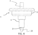
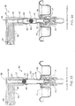
- FIGS. 4 , 5A, and 5B an embodiment not forming part of the present invention is discussed. It is noted that this embodiment is not a bag-on-valve embodiment such that the fitment for a B-O-V valve is not used and the end sealing portion 23 extends directly into an aerosol container with pressurized fluid product (not shown). It is to be appreciated that a dip tube 16 could also be attached to the end of the valve housing 3 for conventional style aerosol container, as desired or necessary.
- FIG. 5A shows this embodiment in an open position allowing the product to be dispensed in the product bag to communicate with the valve stem 7 through the bores 35.
- FIG. 5B shows the valve of this embodiment in a fully closed position with the lower sealing ring 31 preventing the flow of the product to be dispensed into the valve stem 7.
- the bores 35 in this embodiment are shown having a circular profile as opposed to the straight or rectangular profile shown in FIGS. 3A and 3B .
- the shape of the bores 35 can facilitate control over dispensing of product at a high flow rate through the valve.
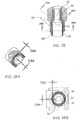
- FIG. 6 illustrates a side view of the valve stern 7 of this embodiment with the bore 35 having a substantially circular shape.
- the bore 35 is a radial orifice in the sidewall of the valve stem 7, and adjacent the lower end thereof, which can have a diameter of between about 1.02 mm - 3.81 mm ⁇ 0.04 - 0.15 inches) and more preferably in the range of about 2,03 mm - 3.05 mm (0.08 - 0.12 inches). It is to be appreciated that the larger bores 35 do not significantly affect the structural integrity of the valve stem 7 since the bores 35 are located close to the bottom end of the valve stem 7 where radial forces from depression and actuation of the valve stem 7 by a user are insignificant.
- the bores 35 are located vertically below the spring 33. It is to be appreciated that axial forces can significantly damage the valve stem where the radial opening is located closer to the top end of the valve stem 7 which the user pushes adjacent the inner gasket 29 as in the known valves.
- the larger bores 35 permit a high amount of product volume to flow info and through the passage 19 of the valve stem 7 at a high flow rate and eventually be discharged into the environment.
- the radial bores or passages can be formed in any desired shape or size which facilitates the desired flow rate of the product.
- the bores can be designed to have a profile and area so that, depending upon how far the valve stem 7 is depressed relative to the sealing edge 24, a desired variable flow rate can be achieved which depends upon the extent that the bore 35 is exposed. Different shapes and sizes may be used for different products to achieve the desired product discharge results.
- the valve stem 7 may have a radial bore 37 which is shaped as a polygon that gradually increases in area as the valve stem 7 and bore 37 are gradually moved axially relative to the sealing edge 24 of the valve housing 3. In the case of the polygon shown in FIG.
- valve stem 7 as the valve stem 7 is depressed axially downward relative to the sealing edge 24, a larger cross-sectional area of the polygon bore 37 becomes progressively exposed to the product to be dispensed in the container and thus permits an increase in relative product flow the more the valve stem 7 is depressed.
- the polygon and circular bores shown in these figures are merely two examples of the type of larger bore shapes, located near or adjacent the bottom end of the valve stem 7 that can readily facilitate dispensing of a larger volume of the product to be dispensed at increased flow rates.
- the metering device comprises a movable ball 42, or possibly a slidable piston or some other member, located within the valve stem 7.
- the metering valve 40 includes a conical or tapered lower ball seat or sealing rim 44 which tapers from the slightly larger diameter of the metering chamber 19 to a slightly smaller diameter of an axial inlet passage 46 that communicates with the radial bores 21 for delivering product to be dispensed from the container to the valve stem 7.
- valve stem 7 also has a conical or tapered upper ball seat or sealing rim 50, located adjacent the outlet orifice 48, and the outlet orifice 48 has a slightly smaller diameter than a diameter of the metering chamber 19.
- the metering ball 42 has a slightly smaller diameter than the diameter of the metering chamber 19 so as to permit the metering ball to dispense a pre-determined quantity of product to be dispensed, while also facilitating return of the metering ball 42, as discussed below in further detail.
- a conventional coupling 52 facilitates coupling/interconnection of an inlet passage 74 of an actuator 60 to the free upper end of the valve stem 7.
- the vertically upper most portion of the valve stem 7 is matingly received by a first end of the conventional coupling 52 while the opposite vertically upper most end of the conventional coupling 52 is received by a lower inlet passage 74 of the actuator 60.
- the outlet orifice 48, of the valve stem 7 is axially aligned with a vertical first passage 56 formed in the actuator 60.
- the product to be dispensed may be dispensed from the actuator 60 either radially, as shown, via a substantially horizontal second passageway 58 or substantially vertically (not shown) via a second passageway 58.
- the substantially horizontal second passageway 58 connects the first passage 56 with a discharge nozzle 62 of the actuator 60 and facilitates dispensing of the product as an aerosol mist, for example.
- the substantially vertical second passageway 58 is substantially vertically aligned with, or a continuation of, the first passage 56.
- An actuation or depression area 66 may be provided along a top surface of the actuator housing 64 in order to facilitate depression of both the actuator 60 and the valve stem 7 and actuation of the metered valve 40.
- An inwardly facing surface of both the upper ball seat or sealing rim 50 and the conventional coupling 52 is typically provided with one, and possibly more, micro groove(s), channel(s) or vent(s) 68.
- These micro groove(s), channel(s) or vent(s) 68 extend along the entire length of the conventional coupling 52 and at least a portion of the upper ball seat or sealing rim 50 to facilitate supplying a small quantity of external air thereto and gradual release of the metering ball 42 from its sealing engagement with the upper sealing seat or rim 50.
- depression of the actuator 60 is discontinued while the surface tension of the product to be dispensed normally maintains engagement between the metering ball 42 and the upper ball seat or sealing rim 50.
- external air is permitted to flow into and along the micro groove(s), channel(s) or vent(s) 68, formed along the length of the conventional coupling 52 and at least a portion of the upper ball seat or sealing rim 50, and assist with gradually breaking the surface tension and thereby releasing the metering ball 42 from its sealing engagement with the upper ball sealing or sealing rim 50.
- the metering ball 42 gradually moves or drops, through the product, contained within the meter chamber 19, back into sealing engagement with the lower ball sealing or sealing rim 44. Further details concerning the other features of the micro groove(s), channel(s) or vent(s) 68 will be provided with respect to Figs. 26-26B which are discussed below.
- the metering valve 40 of the present invention is different from metering valves according to the prior art where the metering device 42 is the only component within the valve stem 7. There are no complicated components or springs, but instead the sealing of the lower portion of the valve stem 7 is achieved by the sealing ring 31 positioned below the lower ball seat or sealing rim 44.
- the sealing ring 31 is located within an annular groove, which is formed in the valve stem 7 closely adjacent, but vertically below, the at least one radial bore(s) 21.
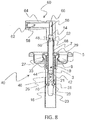
- the lower perimeter edge 26 of the valve housing 3 has a concave curvature 70 which is located to mate and sealingly engage with the sealing ring 31 , when the valve stem 7, is in its normally closed position, as shown in FIG. 8 .
- the metering ball 42 is located in its normal rest position in engagement with the lower ball seat or sealing rim 44.
- the sealing ring 31 is in sealing engagement against the concave curvature 70 of the lower edge 26 of the valve housing 3 and prevents the product to be dispensed from communicating with the at least one radial bore(s) 21.
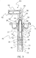
- the actuator 60 is at least partially depressed in order to move the valve stem 7 vertically downward.
- the product then immediately flows in through the at least one radial bore(s) 21 and in the inlet orifice of passage 46, as shown in FIG. 9 .
- the product to be dispensed engages with a vertically lower surface of the ball 42 and rapidly forces the ball 42 out of engagement with the lower ball seat or sealing rim 44 and toward the upper ball seat or sealing rim 50.
- the product to be dispensed flows into and fills the metering chamber 19 of the valve stem 7.
- the product to be dispensed continues forcing the ball 42 through the metering chamber 19 until the ball 42 engages and abuts against the upper ball seat or sealing rim 50.
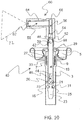
- the metering chamber 19 is then filled with the product to be dispensed, as shown in FIG. 10 , and the valve begins to close.
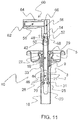
- the depression pressure of the actuator 60 is then removed so that the spring 33 biases the valve back into its closed position thereby preventing the flow of product to be dispensed into the at least one radial bore(s) 21. That is, the sealing ring 31 of the valve stem 7 is again brought back into sealing engagement with the concave curvature 70 of the lower perimeter edge 26 to prevent the flow of product to be dispensed into the at least one radial bore(s) 21, as shown in FIG. 11 .
- the ball 42 is then permitted to be gradually released from its sealing engagement with the upper ball seat or sealing rim 50, due to surface tension, by external air.
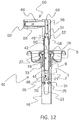
- the external air is permitted to flow into and along the micro groove(s), channel(s) or vent(s) 68, formed along the length of the conventional coupling 52 and at least a portion of the upper ball seat or sealing rim 50, and gradually break the surface tension, thereby releasing the metering ball 42 from its sealing engagement with the upper ball sealing or sealing rim 50, as shown in FIG. 12 .
- the ball 43 eventually rolls or falls through the product filled metering chamber 19, due to gravity, back into sealing engagement with the lower ball seat or sealing rim 44, as shown in FIG. 13 . Once the ball 42 is located in this position, the ball 42 eventually again rests and seals against the lower sealing rim 44, as shown in FIG. 13 .
- the metered valve 40 is now primed and ready to commence dispensing product.
- the actuator 60 is again at least partially depressed and moves the valve stem 7 vertically downward. This ensures that the sealing ring 31 moves vertically downward away from and out of sealing engagement with the concave curvature 70 of the lower edge 26 and facilitates communication between the product to be dispensed and the at least one radial bore(s) 21. Once this occurs, the product then immediately flows in through the at least one radial bore(s) 21 and the inlet passage 46, as shown in FIG. 9 .
- the product engages with the ball 42 and forces the ball 42 out of sealing engagement with the lower ball seat or sealing rim 44 and toward the upper ball seat or sealing rim 50.
- the product which is located within the metering chamber 19, between a vertically upper surface of the ball 42 and the upper ball seat or sealing rim 50, is forced out through the outlet orifice 48.
- the product is then forced into the first and the second passages 56, 58 of the actuator 60 and out through the discharge nozzle 62 in a desired spray pattern 72, as generally indicated by the dashed lines in FIG. 10 .
- the product to be dispensed continues forcing the ball 42 along the metering chamber 19 and again fills the metering chamber 19, for a subsequent dispensing cycle; until the ball 42 engages with and abuts against the upper ball seat or sealing rim 50, as shown in FIG. 11 . As soon as this occurs, a pre-determined quantity of product to be dispensed will be dispensed from the actuator 60. Next, the ball 42 is then permitted to be gradually released from its sealing engagement with the upper ball seat or sealing rim 50. This sealing engagement is typically maintained by the surface tension of the product to be dispensed. Eventually, the ball 42 will roll or fall, due to gravity, through the product filled metering chamber 19, as shown in FIG.
- FIGS. 14-19 a second embodiment of the present invention will now be described in detail. As this additional embodiment is quite similar to the first embodiment of FIGS. 8-13 , similar or like elements are given the same reference numerals.
- the metering valve 40 is accommodated within the actuator 60, instead of the valve stem 7.
- the vertically upper most portion of the valve stem 7 is matingly received by and engages with a lower inlet passage 74 of the actuator 60 so that the outlet orifice 48, of the valve stem 7, is axially aligned with a vertical first passage 56 formed in the actuator 60.
- the product to be dispensed may be dispensed from the actuator 60, according to this embodiment, in a substantially horizontal discharge pattern.
- a second passage 58 is directly interconnected with the first passage 56.
- the second passage 58 communicates with actuator outlet 76 which accommodates a conventional discharge nozzle 62 and facilitates dispensing of the product to be dispensed as a desired aerosol mist, for example.
- actuator outlet 76 accommodates a conventional discharge nozzle 62 and facilitates dispensing of the product to be dispensed as a desired aerosol mist, for example.
- an actuation or depression area 66 is provided along a top surface of the actuator housing 64 in order to facilitate depression of both the actuator 60 and the valve stem 7 in order to actuate the metered valve 40.
- second passage 58 includes a conical or tapered upper ball seat or sealing rim 50, located adjacent the discharge nozzle 62 of the actuator 60.
- the metering ball 42 has a slightly smaller diameter than the diameter of the metering chamber 19, it is undersized by 0,002 - 0.010 mm. This permits the metering ball 42 to move to and fro, along the metering chamber 19, and dispense a pre-determined quantity of product to be dispensed, while also facilitating return of the metering ball 42, as discussed below in further detail, back toward the opposite end of the metering chamber 19.
- the second passage 58 extends completely through the end wail 78 of the actuator 60 and along a substantial portion of the length of the actuator 60 to a location closely adjacent an outlet chamber of the actuator 60.
- An opening 80 which is formed in the end wall 78 of the actuator 60, communicates directly with the external environment.
- a plug member 82 is received within and sealingly engages and closes the opening 80 formed in the end wall 78 of the actuator 60.
- the plug member 82 typically has an interference fit with the opening 80 so as to form a fluid tight seal when engaged therewith.
- An inwardly facing surface of the plug member 82 supports a post 84 and a free end of the post forms a stop surface or rim 44 which prevents further downward travel or movement of the metering ball 42 within the metering chamber 19. That is, the free end of the post 84 forms the lower ball seat or rim 44 which prevents further downward travel of the metering ball 42 within the second passage 58.
- the plug member 82 may alternatively comprise a cylindrical plug (not shown) which has a central aperture therein which extends longitudinally through the cylindrical plug and receives either a slidable or a rotatable post member (not shown), without departing from the scope of the present invention.
- the central aperture and the post member may both be threaded so that rotation of the post member, within the central aperture and relative to the cylindrical plug, in a first direction gradually moves the stop surface or rim 44 of the post member toward the tapered upper ball seat or sealing rim 50 while rotation of the post member, within the central aperture and relative to the cylindrical plug, in an opposite second direction, moves the stop surface or rim 44 of the post member away from the tapered upper ball seat or sealing rim 50.
- Such adjustment of the free end of the post relative to the cylindrical plug, i.e., the stop surface or rim 44 of the metering ball 42 thereby facilitates adjustment of the dispensing volume of the metering chamber 19.
- the post member may be slidable relative to the central aperture and the cylindrical plug. Movement of the post member (not shown), within the central aperture, in a first direction moves the stop surface or rim 44 of the post member toward the tapered upper ball seat or sealing rim 50, while movement of the post member, within the central aperture, in an opposite second direction moves the stop surface or rim 44 of the post member away from the tapered upper ball seat or sealing rim 50. Such movement of the stop surface or rim 44 of the post member, in turn, varies the dispensing volume of the metering chamber 19.
- the second passage 58 is inclined and typically forms an angle of between about 100 degrees and 175 degrees with the first passage 56 and the valve stem 7. More preferably, the second passage 58 forms an angle of between about 110 degrees and 130 degrees with the first passage 56 and the valve stem 7.
- the inclination of the second passage 58 must be sufficient sloped in order to assist with gradually returning the ball 42 back into engagement, due to gravity, with the lower ball seat or rim 44 once the valve doses.
- an inwardly facing surface of the upper ball seat or sealing rim 50 is provided with at least one, or possibly more, micro groove(s), channel(s) or vent(s) 68 which extend along the length of the upper ball seat or sealing rim 50.
- the at least one, or possibly more, micro groove(s), channel(s) or vent(s) 68 permits external air to flow into and along the micro groove(s), channel(s) or vent(s) 68 toward the upper ball seat or sealing rim 50 and facilitates gradual release of the metering ball 42 from its sealing engagement with the upper sealing seat or rim 50.
- depression of the actuator 60 is eliminated while the internal pressure and the surface tension of the product to be dispensed normally maintains engagement between the metering ball 42 and the upper ball seat or sealing rim 50.
- external air is permitted to flow into and along the at least one, or possibly more, micro groove(s), channel(s) or vent(s) 68 toward the upper ball seat or sealing rim 50.
- Such external air gradually breaks the surface tension and thereby releases the metering ball 42 from its sealing engagement with the upper ball sealing or sealing rim 50.
- the metering ball 42 gradually fall, moves or rolls, through the product contained within the meter chamber 19, back into engagement with the lower ball seat or rim 44.
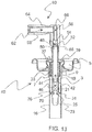
- At least one radial bore(s) 21 is formed in a lower portion of the valve stem 7. When the valve is in its closed position as shown in FIG. 14 , the at least one radial bore(s) 21 is sealed engaged by the gasket 90 so as to prevent any product to be dispensed from flowing into the at least one radial bore(s) 21 and through the valve stem 7 toward the actuator 60.
- the metering ball 42 is located in its normal rest position in engagement with the lower ball seat or rim 44.
- the metering chamber 19 of the actuator 60 located between the upper ball seat or sealing rim 50 and the lower ball seat or rim 44, is completely empty.
- the at least one radial bore(s) 21 is sealed by the gasket 90 and thereby prevents the product to be dispensed from communicating with the at least one radial bore(s) 21.
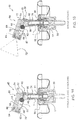
- the actuator 60 is at least partially depressed in order to move the valve stem 7 vertically downward so that the at least one radial bore(s) 21 moves and is no longer sealed by the gasket 90. Such movement facilitates establishing communication between the product to be dispensed and the at least radial bore(s) 21, as shown in FIG. 15 .
- the product then immediately flows in through the at least one radial bore(s) 21 and in the inlet passage, as generally shown in FIG. 15 .
- the product to be dispensed engages with a vertically lower surface of the ball 42 and forces the ball 42 out of engagement with the lower ball seat or rim 44 and toward the upper ball seat or sealing rim 50.
- the product to be dispensed flows into and commences filling the metering chamber 19 of the actuator 60.
- the product to be dispensed continues forcing the ball 42 along and through the metering chamber 19 until the ball 42 eventually engages and abuts against the upper ball seat or sealing rim 50.
- the metering chamber 19 is then completely filled with the product to be dispensed, as shown in FIG. 16 . Once this occurs, thereafter, the valve can now be closed.
- the metering chamber 19 is now completely filled with the product to be dispensed, however, no product has yet been dispensed through the nozzle 62 of the actuator 60 because the metering chamber 19 was initially empty and required priming thereof.
- the ball 42 still remains in abutting engagement against the upper ball seat or sealing rim 50, typically due to surface tension of the product to be dispensed, so as to prevent the flow of any product to be dispensed past this seal.
- the depression pressure of the actuator 60 is then removed or eliminated so that the spring 33 can bias the valve body 17 back into its normally closed position, thereby preventing the flow of any additional product to be dispensed into the at least one radial bore(s) 21 , i.e., the at least one radial bore(s) 21 of the valve stem 7 is again sealingly engaged with the gasket 90 so as to prevent the flow of product to be dispensed into the at least one radial bore(s) 21 , as shown in FIG. 17 .
- the ball 42 is then permitted to be gradually released from its sealing engagement with the upper ball seat or sealing rim 50 by external air which flows in through the nozzle 62 and the actuator outlet 76 of the actuator 60 toward the upper ball seat or sealing rim 50.
- External air eventually flows along the at least one, or possibly more, micro groove(s), channel(s) or vent(s) 68 provided along a surface of upper ball seat or sealing rim 50 and breaks the surface tension of the product to be dispensed and thereby release the metering ball 42 from its sealing engagement with the upper ball sealing or sealing rim 50.
- the ball 42 eventually and gradually falls, moves or rolls, due to gravity, through the product contained within the metering chamber 19 back into engagement with the lower ball seat or rim 44, as shown in FIG. 19 . Once the ball 42 is located in this position, the ball 42 eventually again rests against the ball seat or rim 44.
- the metered valve 40 is now completely primed and ready to commence dispensing product.
- the actuator 60 is again at least partially depressed and moves the at least one radial bore(s) 21 of the valve stem 7 out of sealing engagement with the gasket 90 so as to facilitate communication between the product to be dispensed and the at least one radial bore(s) 21.
- the product then immediately flows in through the at least one radial bore(s) 21 and the inlet passage, as shown in FIG. 15 .
- the product travels along the valve stem 7, exits though the outlet orifice 48 and into the first passage 56.
- the product then flows through the first passage 56 and into the second passage 58 where the product forces the ball 42 out of engagement with the lower ball seat or rim 44 and toward the upper ball seat or sealing rim 50.
- the product which is located in the metering chamber 19, between a front surface of the ball 42 and the upper ball seat or sealing rim 50, is forced out through the outlet chamber 78 and the discharge nozzle 62 of the actuator 60 in a desired spray pattern 72, generally indicated by the dashed lines in FIG. 15 .
- the product to be dispensed continues forcing the ball 42 along the metering chamber 19 until the ball 42 engages with and abuts against the upper ball seat or sealing rim 50, as shown in FIG. 16 , and again fills the metering chamber 19, for a subsequent dispensing cycle.
- a pre-determined quantity of product to be dispensed, from the metering chamber 19, was dispensed by the nozzle 62 of the actuator 60.
- the ball 42 is then permitted to be gradually released from its sealing engagement with the upper ball seat or sealing rim 50, typically maintained by the surface tension of the product to be dispensed.
- the ball 42 falls, moves or roils, due to gravity, as shown in FIG. 18 , through the product which is contained within the metering chamber 19 and back into engagement with the lower ball seat or rim 44, as shown in FIG. 19 .
- the ball 42 is again ready for a subsequent dispensing cycle.
- FIGS. 20-25 a third embodiment of the present invention will now be described in detail. As this additional embodiment is quite similar to the embodiment of FIGS. 8-13 , similar or like elements are given the same reference numerals.
- the valve is a female valve and the metering device 40 is accommodated within a portion of a male valve stem 86 which is releasably engageable with a top recess 88 formed within an upper surface of the valve body 17.
- a top portion of the valve housing 3 engages with a gasket 90 and a mounting cup 5, via crimping process, to secure the valve housing 3 and the gasket 90 to the mounting cup 5.
- An internal portion of the valve housing 3 defines a cavity which accommodates a spring 92 which controls dynamic movement of the valve body 17 with respect to the valve housing 3.
- the spring normally biases the valve body 17 away from a base surface of the cavity into a closed, sealing position in which a perimeter lip 94 of an upper surface of the valve body 17 engages with a lower surface of the gasket 90 and forms a fluid tight perimeter seal therebetween so as to prevent the flow of product through the valve.
- a lower portion of the valve housing 3 is configured so as to engage with and retain a dip tube, a product bag, etc., or some other component, generally designated as element 16, which assists with supplying the product to be dispensed into the cavity of the valve.
- a vertically lower portion of the male valve stem 86 is captively received and retained within the recess 88 formed in the upper surface of the valve body for securing the male valve stem 86 to the valve body 17, e.g., typically by an interference or friction fit.
- a lower side wall of the male valve stem 86 has at least one stem orifice 96 formed therein which permits the product to be dispensed to flow from the cavity defined by the valve housing 3 in through the stem orifice 96, into the male valve stem 86, and toward the metering chamber 19. Such flow occurs when the valve is actuated and the perimeter lip 94 of the valve body 17 is sufficiently spaced from the gasket 90 so as to permit product flow through the valve.
- the metering valve 40 comprises a movable ball 42, or possibly a slidable piston or some other member, located within the male valve stem 86.
- the metering valve 40 includes a lower ball seat or rim 44, which transitions from the slightly larger diameter of the metering chamber 19 into the slightly smaller diameter of a supply passage 98 formed in a lower portion of the male valve stem 86.
- a conventional coupling 52 facilitates coupling/interconnection of the upper free end of the male valve stem 86 with an inlet passage 74 of an actuator 60.
- the vertically upper most portion of the male valve stem 86 is matingly received by a first end of the conventional coupling 52 while the opposite vertically upper most end of the conventional coupling 52 is received by and snugly fits within the inlet passage 74 of the actuator 60. This ensures that the outlet orifice 48 is axially aligned with a vertical first passage 56 formed in the actuator 60.
- the product to be dispensed may be dispensed from the actuator 60 either radially, as shown, via a substantially horizontal second passageway 58 which connects the first passage 56 with a discharge nozzle 62 of the actuator 60 and facilitates dispensing of the product as an aerosol mist, for example.
- it may be dispensed from the actuator 60 substantially vertically (not shown) via the second passageway 58 which is substantially vertically aligned with, e.g., substantially a continuation of, the first passage 56.
- An actuation or depression area 66 may be provided along a top surface of the actuator housing 64 in order to facilitate depression of both the actuator 60 and the male valve stem 86, the valve body and actuation of the metered valve 40.
- the conventional coupling 52 has a conical or tapered upper ball seat or sealing rim 50, located adjacent the outlet orifice 48, and the outlet orifice 48 has a smaller diameter than a diameter of the metering chamber 19.
- the metering ball 42 has a slightly smaller diameter than the diameter of the metering chamber 9 so as to permit the metering ball 42 to dispense a pre-determined quantity of product to be dispensed, while also facilitating return of the metering ball 42 back to its normal rest position, as discussed below in further detail.
- the metering ball 42 is located in its normal rest position in engagement with the lower ball seat or rim 44.
- the metering chamber 19 of the male valve stem 86 located between the upper ball seat or sealing rim 50 and the lower ball seat or rim 44, is completely empty. In this closed position, the perimeter lip 94 is in sealing engagement against the gasket 90 and prevents the product to be dispensed from flowing from the cavity into the stem orifice 96.
- the actuator 60 is at least partially depressed in order to move the valve body 17 vertically downward so that the perimeter lip 94 is sufficiently spaced from the gasket 90 and thereby establishes communication between the cavity and into the stem orifice 96 so that the product to be dispensed can commence flowing, as shown in FIG. 21 .
- the product then immediately flows in through the stem orifice 96 and along the supply passage 98 of the male valve stem 86.
- the product to be dispensed engages with a vertically lower surface of the ball 42 and forces the ball 42 out of engagement with the lower ball seat or rim 44 and toward the upper ball seat or sealing rim 50, as shown in FIG. 21 .
- the product to be dispensed flows into and fills the metering chamber 19. The product to be dispensed continues forcing the ball 42 along and through the metering chamber 19 until the ball 42 eventually engages and abuts against the upper ball seat or sealing rim 50.
- the metering chamber 19 is then filled with the product to be dispensed, as shown in FIG. 22 .
- the valve can be closed so that the perimeter lip 94 is again located in sealing engagement with the gasket 90 and thereby prevents the product to be dispensed from flowing out of the cavity into the stem orifice 96, as shown in FIG. 23 .
- the flow of additional product to be dispensed is automatically discontinued. Thereafter, depression of the actuator 60 is discontinued while the surface tension, of the product to be dispensed, normally maintains the sealing engagement between the metering ball 42 and the upper ball seat or sealing rim 50. Over the course of a few minutes or so, external air is permitted to flow from the external environment into and along the at least one micro groove(s), channel(s) or vent(s) 68 to the upper ball seat or sealing rim 50 and gradually break the surface tension and thereby release the metering ball 42 from its sealing engagement with the upper ball sealing or sealing rim 50. Thereafter, the metering ball 42 gradually falls, moves or rolls, through the product contained within the meter chamber 19, as shown in FIG. 24 , back into sealing engagement with the lower ball seat or rim 44, as shown in FIG. 25 .
- the metering ball 42 prior to an initial priming of the valve, the metering ball 42 is located in its normal rest position in engagement with the lower ball seat or rim 44.
- the perimeter lip 94 is sealingly engaged with the gasket 90 and prevents the product to be dispensed from communicating with the stem orifice 96.
- the actuator 60 is at least partially depressed in order to move the male valve stem 86 and the valve body vertically downward. This ensures that the perimeter lip 94 correspondingly moves vertically downward away from and out of sealing engagement with the gasket 90 to facilitate establishing communication between the product to be dispensed and the stem orifice 96, as shown in FIG. 21 .
- the product then immediately flow in through the at least one stem orifice 96 and into the supply passage 98 of the male valve stem 86, as shown in FIGS. 21 and 22 .
- the product to be dispensed engages with a vertically lower surface of the ball 42 and forces the ball 42 out of engagement with the lower ball seat or rim 44 and toward the upper ball seat or sealing rim 50, as shown in FIG. 21 .
- the product to be dispensed flows into and fills the metering chamber 19 of the male valve stem 86.
- the product to be dispensed continues forcing the ball 42 through the metering chamber 19 until the ball 42 engages and abuts against the upper ball seat or sealing rim 50, as shown in FIG. 22 , so that the metering chamber 19 is then filled with the product to be dispensed and the valve can then be closed.
- the metering chamber 9 is now completely filled with the product to be dispensed, however, no product has yet been dispensed through the nozzle 62 of the actuator 60 because the male valve stem 86 was initially empty and required priming of the metering chamber 19.
- the metering ball 42 still remains in abutting engagement against the upper ball seat or sealing rim 50 so as to prevent the flow of any product to be dispensed past this seal.
- the depression pressure of the actuator 60 is then removed or eliminated so that the spring 33 biases the valve body 17 back into its normally closed position thereby preventing the flow of additional product to be dispensed from the cavity into the at least one stem orifice 96, i.e., the perimeter lip 94 of the valve body 17 is again brought into sealing engagement with the gasket 90 to prevent the flow of product to be dispensed into the at least one stem orifice 96, as shown in FIG. 23 .
- the ball 42 is then permitted to be gradually released from its sealing engagement with the upper ball seat or sealing rim 50 by external air which flows into and along the one or more micro grooves, channels or vents 68 and the external air eventually breaks the surface tension and thereby releasing the metering ball 42 from its sealing engagement with the upper ball sealing or sealing rim 50.
- the ball 42 eventually falls, moves or rolls through the product filled metering chamber 19, due to gravity as generally shown in F!G. 24, back into engagement with the lower ball seat or rim 44, as shown in FIG. 25 . Once the ball 42 is located in this position, the ball 42 eventually again rests against the lower ball seat or rim 44 and is ready for another dispensing cycle.
- the metered valve 40 is now completely primed and ready to commence dispensing product.
- the actuator 60 is again at least partially depressed and moves the valve body vertically downward so that the perimeter lip 94 moves vertically downward away from and out of sealing engagement with the gasket 90 so as to permit product flow from the cavity into the at least one stem orifice 96 and facilitate communication between the product to be dispensed and the supply passage 98 of the male valve stem 86.
- the product then immediately flows in through the at least one stem orifice 96 and the supply passage 98 of the male valve stem 86, as shown in FIG. 21 .
- the product As the product flows through the stem orifice 96 of the male valve stem 86, the product engages with the ball 42 and forces the ball 42 out of sealing engagement with the lower ball seat or rim 44 and toward the upper ball seat or sealing rim 50.
- the product As the ball 42 moves toward the upper ball seat or sealing rim 50, the product which is located in the metering chamber 19, between a vertically upper surface of the ball 42 and the upper ball seat or sealing rim 50, is displaced and forced out through the outlet orifice 48.
- the product is then forced out through the first and the second passages 56, 58 of the actuator 60 and through the discharge nozzle 62 for dispensing in a desired spray pattern 72, as generally indicated by the dashed lines in FIG. 21 .
- depression of the actuator 60 is removed or eliminated and the metering ball 42 is then permitted to be gradually released from its sealing engagement with the upper ball seat or sealing rim 50, by external air which is permitted to flow to the at least one, or possibly more, micro groove(s), channel(s) or vent(s) 68 and break the surface tension and thereby releasing the metering ball 42 from its sealing engagement with the upper ball sealing or sealing rim 50.
- the metering ball 42 eventually falls, moves or rolls, due to gravity, through the product filled metering chamber 19 back into engagement with the lower ball seat or rim 44, as shown in FIG. 24 .
- the metering ball 42 again rests against the lower ball seat or rim 44, as shown in FIG. 25 , and is again ready for a subsequent dispensing cycle.
- the conventional coupling 52 has at least one, and possibly more, micro groove(s), channel(s) or vent(s) 68 formed in an inwardly facing surface thereof.
- the at least one, and possibly more, micro groove(s), channel(s) or vent(s) 68 extends continuously and uninterrupted along the inwardly facing surface, from a lower bottom edge of the conventional coupling 52 to and along at least a major portion of the upper ball seat or sealing rim 50.
- Each micro groove(s), channel(s) or vent(s) 68 typically has a height of about 0.127 ⁇ 0.0762 mm (0.005 ⁇ 0.003) inches, and a width of about 0.127 ⁇ 0.0762 mm (0.005 ⁇ 0.003 inches).
- Each micro groove(s), channel(s) or vent(s) 68 has a cross-sectional flow area which is designed to permit external air to flow there along to the upper ball seat or sealing rim 50 and eventually assist with breaking the surface tension seal achieved by the product to be dispensed, between the metering ball 42 and the upper ball seat or sealing ring rim 50.
- Such cross-sectional flow area is also designed to be sufficiently small so as to prevent any significant amount of the product to be dispensed from flowing out through the micro groove(s), channel(s) or vent(s) 68.
- the metering chamber 19 typically has a length of between 25.984 ⁇ 2.54 mm (1.023 ⁇ 0.100 inches) and between 8.484 ⁇ 2.54 mm (0.334 ⁇ 0.100 inches) and a diameter of between 3.556 mm (0.140 inches) and between 2.794 mm (0.110 inches), preferably about 3.226 mm (0.127 inches).
- the metering chamber 19 typically has a volume of between 50 and 100 micrometers, depending upon the particular application. It is to be appreciated that the length and/or the diameter of the metering chamber 19 are designed or selected so as to accommodate the desired predetermined quantity of product to be dispensed during each dispensing cycle of the metering ball 42.
Claims (15)
- Valve de distribution comprenant une valve de dosage (40) pour une utilisation dans une application d'aérosol sous pression, la valve de distribution comprenant : une coupelle de montage (5) supportant un joint (90), et une ouverture s'étendant à travers la coupelle de montage (5) et le joint (90) pour faciliter la réception d'une tige de valve (86) ; un boîtier de valve (3) définissant une cavité (15), le boîtier de valve (3) étant retenu de manière captive par la coupelle de montage (5), le joint (90) étant pris en sandwich entre le boîtier de valve (3) et la coupelle de montage (5), un corps de valve (17) étant logé dans la cavité de valve (15), et un ressort (33) étant logé dans la cavité (15) et poussant le corps de valve (17) contre le joint (90) dans une position normalement fermée pour empêcher l'écoulement à travers la valve de distribution ; une partie inférieure du boîtier de valve (3) comprenant un passage qui facilite la communication entre le produit à distribuer et la cavité (15) du boîtier de valve (3) ; la tige de valve (86) étant couplée au corps de valve (17), et la tige de valve (86) s'étendant vers l'extérieur à travers l'ouverture formée dans le joint (90) et l'ouverture formée dans la coupelle de montage (5) ; un actionneur (60) étant supporté à proximité d'une extrémité libre de la tige de valve (86) pour faciliter la distribution du produit à distribuer par la valve de distribution ; et
la valve de dosage (40) comprenant : une chambre de dosage (19) délimitée par un siège de valve de dosage (50) et une butée (44), et un élément de dosage (42) étant mobile, à l'intérieur de la chambre de dosage (19), entre la butée (44) et le siège de valve (50) pour faciliter la distribution d'une quantité prédéterminée du produit à distribuer, et, après l'amorçage de la valve de dosage (40), une quantité prédéterminée du produit étant distribuée à partir de la chambre de dosage (19) à chaque fois que la valve de dosage (40) est actionnée ; et
caractérisée en ce que le siège de valve de dosage (50) comprend au moins un micro-évent (68) formé à l'intérieur, ledit au moins un micro-évent (68) étant situé en aval du joint (90) de manière à faciliter l'alimentation en air externe du siège de valve de dosage (50) et à rompre un joint formé par la tension de surface du produit à distribuer et à libérer ainsi l'élément de dosage (42) de son engagement étanche avec le siège de valve de dosage (50) de sorte que l'élément de dosage (42) puisse se déplacer du siège de valve de dosage (50) en retour en engagement avec la butée (44) pour un autre cycle de distribution. - Valve de distribution comprenant la valve de dosage (40) selon la revendication 1, caractérisée en ce que la valve de distribution comprend un ou plusieurs des éléments suivants :la chambre de dosage (19) a une longueur comprise entre 25.984 ± 2.54 mm et 8.484 ± 2.54 mm et un diamètre compris entre 3.556mm et 2.794 mm ;la chambre de dosage (19) a un volume compris entre 50 et 100 micromètres ; ouledit au moins un micro-évent (68) a une hauteur d'environ 0.127 mm, et une largeur d'environ 0.127 mm.
- Valve de distribution comprenant la valve de dosage (40) selon la revendication 1, caractérisée en ce que l'élément de dosage (42) comprend une bille de dosage (42) qui a un diamètre qui est légèrement inférieur à un diamètre de la chambre de dosage (19) de manière à permettre à la bille de dosage (42) de se déplacer en va-et-vient, le long de la chambre de dosage (19), et de distribuer une quantité prédéterminée de produit à distribuer, tout en facilitant également le retour de la bille de dosage (42) vers la butée (44) de la chambre de dosage (19).
- Valve de distribution comprenant la valve de dosage (40) selon la revendication 1, caractérisée en ce que la valve de distribution comprend un ou plusieurs des éléments suivants :une partie inférieure du boîtier de valve (3) est configurée pour s'engager avec et retenir un composant (16) qui aide à fournir le produit à distribuer dans la cavité (15) du boîtier de valve (3) ; etla chambre de dosage (19), l'élément de dosage (42), le siège de valve de dosage (50) et la butée (44) sont tous logés dans l'actionneur (60).
- Valve de distribution comprenant la valve de dosage (40) selon la revendication 1, caractérisée en ce qu'une extrémité d'un passage de l'actionneur (60) communique avec une chambre de sortie (76) qui reçoit une buse (62) tandis qu'une extrémité opposée du passage communique avec un environnement externe via une ouverture (80) est formée dans une paroi d'extrémité (78) de l'actionneur (60), et un élément de bouchon (82) s'engage de manière étanche et ferme l'ouverture (80) formée dans la paroi d'extrémité (78).
- Valve de distribution comprenant la valve de dosage (40) selon la revendication 5, caractérisée en ce que la valve de distribution comprend l'un ou les deux des éléments suivants :l'élément de bouchon (82) a un ajustement serré avec l'ouverture (80) et forme un joint étanche aux fluides lors de son engagement avec celle-ci, et une surface de l'élément de bouchon (82) tournée vers l'intérieur forme la butée (44) qui empêche tout mouvement supplémentaire de l'élément de dosage (42) à l'intérieur de la chambre de dosage (19) ; etle passage recevant la chambre de dosage (19) est incliné par rapport à la tige de valve (86) et forme un angle compris entre environ 100 degrés et 175 degrés avec la tige de valve (86), et l'angle d'inclinaison est suffisamment incliné pour faciliter le retour progressif de l'élément de dosage (42) en contact, par gravité, avec la butée (44) une fois que la valve de distribution se ferme.
- Valve de distribution comprenant la valve de dosage (40) selon la revendication 1, caractérisée en ce qu'au moins un alésage radial (21) est formé dans une partie inférieure de la tige de valve (86), lorsque la valve de distribution est en position fermée, ledit au moins un alésage radial (21) s'engage de manière étanche avec le joint (90) de manière à empêcher tout produit à distribuer de s'écouler dans ledit au moins un alésage radial (21) et la tige de valve (86) vers la chambre de dosage (19), mais lorsque la valve de distribution est en position ouverte, ledit au moins un alésage radial (21) est espacé du joint (90) de manière à permettre au produit à distribuer de s'écouler à travers ledit au moins un alésage radial (21) et la tige de valve (86) vers la chambre de dosage (19).
- Valve de distribution comprenant la valve de dosage (40) selon la revendication 1, caractérisée en ce que la valve de distribution est une valve femelle ;
la tige de valve (86) peut s'engager de manière amovible, par un ajustement d'interférence ou de friction, avec un évidement supérieur (88) formé à l'intérieur d'une surface supérieure du corps de valve (17) ; et
la chambre de dosage (19), l'élément de dosage (42), le siège de valve de dosage (50) et la butée (44) sont tous logés dans la tige de valve (86), entre le corps de valve (17) et l'actionneur (60). - Valve de distribution comprenant la valve de dosage (40) selon la revendication 8, caractérisée en ce qu'une paroi latérale inférieure de la tige de valve (86) comporte au moins un orifice de tige (96) formé dans celle-ci qui permet au produit à distribuer de s'écouler, lorsque la valve de distribution est actionnée, de la cavité (15) dans la tige de valve (86) et vers la chambre de dosage (19).
- Valve de distribution comprenant la valve de dosage (40) selon la revendication 9, caractérisée en ce que le corps de valve (17) supporte une lèvre périphérique (94) qui est normalement sollicitée, par le ressort (33), en engagement étanche avec le joint (90) lorsque la valve de distribution est fermée, et lorsque la lèvre périphérique (94) est suffisamment espacée du joint (90) en raison de la dépression de l'actionneur (60) et de la tige de valve (86), le produit à disposer est capable de s'écouler à travers la valve de distribution vers la chambre de dosage (19).
- Valve de distribution comprenant la valve de dosage (40) selon la revendication 1, caractérisée en ce qu'un couplage (52) facilite le couplage d'une extrémité libre de la tige de valve (86) avec un passage d'entrée (74) d'un actionneur (60), et l'extrémité libre de la tige de valve (86) est reçue de façon complémentaire par une première extrémité du couplage (52) tandis qu'une extrémité opposée verticalement la plus haute du couplage (52) est reçue et s'adapte dans le passage d'entrée (74) de l'actionneur (60).
- Valve de distribution comprenant la valve de dosage (40) selon la revendication 11, caractérisée en ce que ledit moins un micro-évent (68) s'étend le long d'une surface tournée vers l'intérieur du couplage (52), entre le couplage (52) et la tige de valve (86), jusqu'au siège de valve de dosage (50), et ledit au moins un micro-évent (68) s'étend le long d'au moins une partie du siège de valve de dosage (50) pour faciliter l'alimentation en air externe de celui-ci.
- Valve de distribution comprenant la valve de dosage (40) selon la revendication 3, caractérisée en ce que la butée (44) comprend un second siège de valve pour recevoir et s'engager avec la bille de dosage (42) lorsque la valve de distribution est en position fermée.
- Valve de distribution comprenant la valve de dosage (40) selon la revendication 1, caractérisée en ce que la chambre de dosage (19) a une longueur comprise entre 25,984 mm et 8,484 mm, et un diamètre de 3,226 mm, et ledit au moins un micro-évent (68) a une hauteur d'environ 0,127 mm et une largeur d'environ 0,127 mm.
- Procédé de distribution d'un produit à distribuer à partir d'une valve de distribution qui comprend une coupelle de montage (5) supportant un joint (90), et une ouverture (80) s'étendant à travers la coupelle de montage (5) et le joint (90) pour faciliter la réception d'une tige de valve (86) ; un boîtier de valve (3) définissant une cavité (15), le boîtier de valve (3) étant retenu de manière captive par la coupelle de montage (5), le joint (90) étant pris en sandwich entre le boîtier de valve (3) et la coupelle de montage (5), un corps de valve (17) étant logé dans la cavité de valve (15), et un ressort (33) étant logé dans la cavité (15) et poussant le corps de valve (17) contre le joint (90) dans une position normalement fermée pour empêcher l'écoulement à travers la valve de distribution ; une partie inférieure du boîtier de valve (3) comprenant un passage qui facilite la communication entre le produit à distribuer et la cavité (15) du boîtier de valve (3) ; la tige de valve (86) étant couplée au corps de valve (17), et la tige de valve (86) s'étendant vers l'extérieur à travers l'ouverture formée dans le joint (90) et l'ouverture formée dans la coupelle de montage (5) ; un actionneur (60) étant supporté à proximité d'une extrémité libre de la tige de valve (86) pour faciliter la distribution du produit à distribuer par la valve de distribution ; et la valve de dosage (40) comprend une chambre de dosage (19) délimitée par un siège de valve de dosage (50) et une butée (44), et un élément de dosage (42) étant mobile, à l'intérieur de la chambre de dosage (19), entre la butée (44) et le siège de valve (50) pour faciliter la distribution d'une quantité prédéterminée du produit à distribuer, et, après l'amorçage de la valve de dosage (40), une quantité prédéterminée du produit étant distribuée à partir de la chambre de dosage (19) à chaque fois que la valve de dosage (40) est actionnée ; et
caractérisé en ce que le siège de valve de dosage (50) comprend au moins un micro-évent (68) formé à l'intérieur, ledit au moins un micro-évent (68) étant situé en aval du joint (90) de manière à faciliter l'alimentation en air externe du siège de valve de dosage (50) et à rompre un joint formé par la tension de surface du produit à distribuer et à libérer ainsi l'élément de dosage (42) de son engagement étanche avec le siège de valve de dosage (50) de sorte que l'élément de dosage (42) puisse se déplacer du siège de valve de dosage (50) en retour en engagement avec la butée (44) pour un autre cycle de distribution, le procédé comprenant les étapes suivantes :enfoncer la tige de valve (86) ;doser la quantité prédéterminée du produit distribué à partir de la chambre de dosage (19), lorsque l'élément de dosage (42) se déplace de la butée (44) vers le siège de valve ; etpermettre à l'air de s'écouler vers ledit au moins un micro-évent (68) et de briser le joint formé par la tension de surface du produit à distribuer et de libérer l'élément de dosage (42) de son engagement étanche avec le siège de valve de dosage (50).
Priority Applications (1)
| Application Number | Priority Date | Filing Date | Title |
|---|---|---|---|
| PL15748520T PL3105147T3 (pl) | 2014-02-14 | 2015-02-13 | Zawór dozujący obejmujący zawór odmierzający |
Applications Claiming Priority (2)
| Application Number | Priority Date | Filing Date | Title |
|---|---|---|---|
| US14/181,219 US9254954B2 (en) | 2010-08-18 | 2014-02-14 | Metering valve |
| PCT/US2015/015799 WO2015123511A1 (fr) | 2014-02-14 | 2015-02-13 | Valve de distribution comprenant une valve de dosage |
Publications (3)
| Publication Number | Publication Date |
|---|---|
| EP3105147A1 EP3105147A1 (fr) | 2016-12-21 |
| EP3105147A4 EP3105147A4 (fr) | 2017-11-08 |
| EP3105147B1 true EP3105147B1 (fr) | 2020-10-14 |
Family
ID=53800653
Family Applications (1)
| Application Number | Title | Priority Date | Filing Date |
|---|---|---|---|
| EP15748520.2A Active EP3105147B1 (fr) | 2014-02-14 | 2015-02-13 | Valve de distribution comprenant une valve de dosage |
Country Status (6)
| Country | Link |
|---|---|
| EP (1) | EP3105147B1 (fr) |
| AU (1) | AU2015218380B2 (fr) |
| CA (1) | CA2937554C (fr) |
| ES (1) | ES2848202T3 (fr) |
| PL (1) | PL3105147T3 (fr) |
| WO (1) | WO2015123511A1 (fr) |
Families Citing this family (2)
| Publication number | Priority date | Publication date | Assignee | Title |
|---|---|---|---|---|
| DE102017100559A1 (de) * | 2017-01-12 | 2018-07-12 | Carl Hoernecke Chem. Fabrik Gmbh & Co. Kg | Getränkedose |
| CN109330420B (zh) * | 2018-10-26 | 2020-07-03 | 江苏特味浓生物技术开发有限公司 | 一种生抽调味料定量出液装置 |
Family Cites Families (9)
| Publication number | Priority date | Publication date | Assignee | Title |
|---|---|---|---|---|
| US2705094A (en) * | 1950-03-20 | 1955-03-29 | Jr Alleyne C Howell | Metering valve |
| US2778543A (en) * | 1953-07-27 | 1957-01-22 | Harry B Hollander | Metering dispenser |
| FR1219745A (fr) * | 1958-04-09 | 1960-05-19 | Perfectionnements aux distributeurs de fluide sous pression | |
| NL286976A (fr) * | 1961-12-20 | 1900-01-01 | ||
| FR1598257A (fr) * | 1968-12-03 | 1970-07-06 | ||
| JPS5646858Y2 (fr) * | 1977-05-16 | 1981-11-02 | ||
| JP5164109B2 (ja) * | 2008-08-01 | 2013-03-13 | 株式会社三谷バルブ | 定量噴射機構および、この定量噴射機構を備えたエアゾール式製品 |
| CN102725209A (zh) * | 2009-10-09 | 2012-10-10 | 索尔福德大学 | 液体分配仪器 |
| US20120043353A1 (en) * | 2010-08-18 | 2012-02-23 | Summit Packaging Systems, Inc. | High flow aerosol valve |
-
2015
- 2015-02-13 CA CA2937554A patent/CA2937554C/fr active Active
- 2015-02-13 EP EP15748520.2A patent/EP3105147B1/fr active Active
- 2015-02-13 PL PL15748520T patent/PL3105147T3/pl unknown
- 2015-02-13 AU AU2015218380A patent/AU2015218380B2/en active Active
- 2015-02-13 WO PCT/US2015/015799 patent/WO2015123511A1/fr active Application Filing
- 2015-02-13 ES ES15748520T patent/ES2848202T3/es active Active
Non-Patent Citations (1)
| Title |
|---|
| None * |
Also Published As
| Publication number | Publication date |
|---|---|
| CA2937554C (fr) | 2023-03-14 |
| EP3105147A1 (fr) | 2016-12-21 |
| CA2937554A1 (fr) | 2015-08-20 |
| WO2015123511A1 (fr) | 2015-08-20 |
| ES2848202T3 (es) | 2021-08-05 |
| AU2015218380B2 (en) | 2019-03-07 |
| PL3105147T3 (pl) | 2021-09-13 |
| AU2015218380A1 (en) | 2016-08-04 |
| EP3105147A4 (fr) | 2017-11-08 |
Similar Documents
| Publication | Publication Date | Title |
|---|---|---|
| US10384858B2 (en) | Dispensing valve incorporating high flow rate feature | |
| US9254954B2 (en) | Metering valve | |
| EP2605980B1 (fr) | Soupape aerosol à haut débit | |
| US10174884B2 (en) | Valve stem for a compressible valve | |
| US5593065A (en) | Metered dual dispenser cap for squeeze containers | |
| CA2917071C (fr) | Partie de separateur pour recipients | |
| US7036685B1 (en) | Multi-valve delivery system | |
| CN104520209A (zh) | 顺序输送阀设备和方法 | |
| JP2016529169A5 (fr) | ||
| EP3105147B1 (fr) | Valve de distribution comprenant une valve de dosage | |
| US20230415973A1 (en) | An aerosol metering valve system and a container comprising an aerosol metering valve system | |
| US11787619B2 (en) | Valve for pressurized container | |
| JPS62208380A (ja) | バルブアセンブリおよびバルブアセンブリに使用するアダプタ | |
| CA3172216A1 (fr) | Tete de distribution pour un recipient d'aerosol et recipient d'aerosol comprenant une telle tete |
Legal Events
| Date | Code | Title | Description |
|---|---|---|---|
| PUAI | Public reference made under article 153(3) epc to a published international application that has entered the european phase |
Free format text: ORIGINAL CODE: 0009012 |
|
| STAA | Information on the status of an ep patent application or granted ep patent |
Free format text: STATUS: REQUEST FOR EXAMINATION WAS MADE |
|
| 17P | Request for examination filed |
Effective date: 20160727 |
|
| AK | Designated contracting states |
Kind code of ref document: A1 Designated state(s): AL AT BE BG CH CY CZ DE DK EE ES FI FR GB GR HR HU IE IS IT LI LT LU LV MC MK MT NL NO PL PT RO RS SE SI SK SM TR |
|
| AX | Request for extension of the european patent |
Extension state: BA ME |
|
| DAX | Request for extension of the european patent (deleted) | ||
| A4 | Supplementary search report drawn up and despatched |
Effective date: 20171006 |
|
| RIC1 | Information provided on ipc code assigned before grant |
Ipc: B65D 83/38 20060101ALN20170929BHEP Ipc: B65D 83/54 20060101ALI20170929BHEP Ipc: B65D 83/44 20060101AFI20170929BHEP Ipc: B65D 83/62 20060101ALI20170929BHEP |
|
| STAA | Information on the status of an ep patent application or granted ep patent |
Free format text: STATUS: EXAMINATION IS IN PROGRESS |
|
| 17Q | First examination report despatched |
Effective date: 20190830 |
|
| REG | Reference to a national code |
Ref country code: DE Ref legal event code: R079 Ref document number: 602015060448 Country of ref document: DE Free format text: PREVIOUS MAIN CLASS: B65D0083140000 Ipc: B65D0083440000 |
|
| GRAP | Despatch of communication of intention to grant a patent |
Free format text: ORIGINAL CODE: EPIDOSNIGR1 |
|
| STAA | Information on the status of an ep patent application or granted ep patent |
Free format text: STATUS: GRANT OF PATENT IS INTENDED |
|
| RIC1 | Information provided on ipc code assigned before grant |
Ipc: B65D 83/62 20060101ALI20200609BHEP Ipc: B65D 83/44 20060101AFI20200609BHEP Ipc: B65D 83/38 20060101ALN20200609BHEP Ipc: B65D 83/54 20060101ALI20200609BHEP |
|
| INTG | Intention to grant announced |
Effective date: 20200706 |
|
| GRAS | Grant fee paid |
Free format text: ORIGINAL CODE: EPIDOSNIGR3 |
|
| GRAA | (expected) grant |
Free format text: ORIGINAL CODE: 0009210 |
|
| STAA | Information on the status of an ep patent application or granted ep patent |
Free format text: STATUS: THE PATENT HAS BEEN GRANTED |
|
| AK | Designated contracting states |
Kind code of ref document: B1 Designated state(s): AL AT BE BG CH CY CZ DE DK EE ES FI FR GB GR HR HU IE IS IT LI LT LU LV MC MK MT NL NO PL PT RO RS SE SI SK SM TR |
|
| REG | Reference to a national code |
Ref country code: GB Ref legal event code: FG4D |
|
| REG | Reference to a national code |
Ref country code: AT Ref legal event code: REF Ref document number: 1323359 Country of ref document: AT Kind code of ref document: T Effective date: 20201015 Ref country code: CH Ref legal event code: EP |
|
| REG | Reference to a national code |
Ref country code: DE Ref legal event code: R096 Ref document number: 602015060448 Country of ref document: DE |
|
| REG | Reference to a national code |
Ref country code: IE Ref legal event code: FG4D |
|
| REG | Reference to a national code |
Ref country code: NL Ref legal event code: FP |
|
| REG | Reference to a national code |
Ref country code: GR Ref legal event code: EP Ref document number: 20210400052 Country of ref document: GR Effective date: 20210215 |
|
| REG | Reference to a national code |
Ref country code: AT Ref legal event code: MK05 Ref document number: 1323359 Country of ref document: AT Kind code of ref document: T Effective date: 20201014 |
|
| PG25 | Lapsed in a contracting state [announced via postgrant information from national office to epo] |
Ref country code: NO Free format text: LAPSE BECAUSE OF FAILURE TO SUBMIT A TRANSLATION OF THE DESCRIPTION OR TO PAY THE FEE WITHIN THE PRESCRIBED TIME-LIMIT Effective date: 20210114 Ref country code: FI Free format text: LAPSE BECAUSE OF FAILURE TO SUBMIT A TRANSLATION OF THE DESCRIPTION OR TO PAY THE FEE WITHIN THE PRESCRIBED TIME-LIMIT Effective date: 20201014 Ref country code: PT Free format text: LAPSE BECAUSE OF FAILURE TO SUBMIT A TRANSLATION OF THE DESCRIPTION OR TO PAY THE FEE WITHIN THE PRESCRIBED TIME-LIMIT Effective date: 20210215 Ref country code: RS Free format text: LAPSE BECAUSE OF FAILURE TO SUBMIT A TRANSLATION OF THE DESCRIPTION OR TO PAY THE FEE WITHIN THE PRESCRIBED TIME-LIMIT Effective date: 20201014 |
|
| REG | Reference to a national code |
Ref country code: LT Ref legal event code: MG4D |
|
| PG25 | Lapsed in a contracting state [announced via postgrant information from national office to epo] |
Ref country code: AT Free format text: LAPSE BECAUSE OF FAILURE TO SUBMIT A TRANSLATION OF THE DESCRIPTION OR TO PAY THE FEE WITHIN THE PRESCRIBED TIME-LIMIT Effective date: 20201014 Ref country code: BG Free format text: LAPSE BECAUSE OF FAILURE TO SUBMIT A TRANSLATION OF THE DESCRIPTION OR TO PAY THE FEE WITHIN THE PRESCRIBED TIME-LIMIT Effective date: 20210114 Ref country code: LV Free format text: LAPSE BECAUSE OF FAILURE TO SUBMIT A TRANSLATION OF THE DESCRIPTION OR TO PAY THE FEE WITHIN THE PRESCRIBED TIME-LIMIT Effective date: 20201014 Ref country code: IS Free format text: LAPSE BECAUSE OF FAILURE TO SUBMIT A TRANSLATION OF THE DESCRIPTION OR TO PAY THE FEE WITHIN THE PRESCRIBED TIME-LIMIT Effective date: 20210214 Ref country code: SE Free format text: LAPSE BECAUSE OF FAILURE TO SUBMIT A TRANSLATION OF THE DESCRIPTION OR TO PAY THE FEE WITHIN THE PRESCRIBED TIME-LIMIT Effective date: 20201014 |
|
| PG25 | Lapsed in a contracting state [announced via postgrant information from national office to epo] |
Ref country code: HR Free format text: LAPSE BECAUSE OF FAILURE TO SUBMIT A TRANSLATION OF THE DESCRIPTION OR TO PAY THE FEE WITHIN THE PRESCRIBED TIME-LIMIT Effective date: 20201014 |
|
| REG | Reference to a national code |
Ref country code: DE Ref legal event code: R097 Ref document number: 602015060448 Country of ref document: DE |
|
| PG25 | Lapsed in a contracting state [announced via postgrant information from national office to epo] |
Ref country code: SM Free format text: LAPSE BECAUSE OF FAILURE TO SUBMIT A TRANSLATION OF THE DESCRIPTION OR TO PAY THE FEE WITHIN THE PRESCRIBED TIME-LIMIT Effective date: 20201014 Ref country code: EE Free format text: LAPSE BECAUSE OF FAILURE TO SUBMIT A TRANSLATION OF THE DESCRIPTION OR TO PAY THE FEE WITHIN THE PRESCRIBED TIME-LIMIT Effective date: 20201014 Ref country code: CZ Free format text: LAPSE BECAUSE OF FAILURE TO SUBMIT A TRANSLATION OF THE DESCRIPTION OR TO PAY THE FEE WITHIN THE PRESCRIBED TIME-LIMIT Effective date: 20201014 Ref country code: SK Free format text: LAPSE BECAUSE OF FAILURE TO SUBMIT A TRANSLATION OF THE DESCRIPTION OR TO PAY THE FEE WITHIN THE PRESCRIBED TIME-LIMIT Effective date: 20201014 Ref country code: RO Free format text: LAPSE BECAUSE OF FAILURE TO SUBMIT A TRANSLATION OF THE DESCRIPTION OR TO PAY THE FEE WITHIN THE PRESCRIBED TIME-LIMIT Effective date: 20201014 Ref country code: LT Free format text: LAPSE BECAUSE OF FAILURE TO SUBMIT A TRANSLATION OF THE DESCRIPTION OR TO PAY THE FEE WITHIN THE PRESCRIBED TIME-LIMIT Effective date: 20201014 |
|
| REG | Reference to a national code |
Ref country code: ES Ref legal event code: FG2A Ref document number: 2848202 Country of ref document: ES Kind code of ref document: T3 Effective date: 20210805 |
|
| PLBE | No opposition filed within time limit |
Free format text: ORIGINAL CODE: 0009261 |
|
| STAA | Information on the status of an ep patent application or granted ep patent |
Free format text: STATUS: NO OPPOSITION FILED WITHIN TIME LIMIT |
|
| PG25 | Lapsed in a contracting state [announced via postgrant information from national office to epo] |
Ref country code: DK Free format text: LAPSE BECAUSE OF FAILURE TO SUBMIT A TRANSLATION OF THE DESCRIPTION OR TO PAY THE FEE WITHIN THE PRESCRIBED TIME-LIMIT Effective date: 20201014 |
|
| 26N | No opposition filed |
Effective date: 20210715 |
|
| PG25 | Lapsed in a contracting state [announced via postgrant information from national office to epo] |
Ref country code: MC Free format text: LAPSE BECAUSE OF FAILURE TO SUBMIT A TRANSLATION OF THE DESCRIPTION OR TO PAY THE FEE WITHIN THE PRESCRIBED TIME-LIMIT Effective date: 20201014 |
|
| REG | Reference to a national code |
Ref country code: BE Ref legal event code: MM Effective date: 20210228 |
|
| PG25 | Lapsed in a contracting state [announced via postgrant information from national office to epo] |
Ref country code: LI Free format text: LAPSE BECAUSE OF NON-PAYMENT OF DUE FEES Effective date: 20210228 Ref country code: LU Free format text: LAPSE BECAUSE OF NON-PAYMENT OF DUE FEES Effective date: 20210213 Ref country code: AL Free format text: LAPSE BECAUSE OF FAILURE TO SUBMIT A TRANSLATION OF THE DESCRIPTION OR TO PAY THE FEE WITHIN THE PRESCRIBED TIME-LIMIT Effective date: 20201014 Ref country code: CH Free format text: LAPSE BECAUSE OF NON-PAYMENT OF DUE FEES Effective date: 20210228 |
|
| PG25 | Lapsed in a contracting state [announced via postgrant information from national office to epo] |
Ref country code: SI Free format text: LAPSE BECAUSE OF FAILURE TO SUBMIT A TRANSLATION OF THE DESCRIPTION OR TO PAY THE FEE WITHIN THE PRESCRIBED TIME-LIMIT Effective date: 20201014 |
|
| PG25 | Lapsed in a contracting state [announced via postgrant information from national office to epo] |
Ref country code: IE Free format text: LAPSE BECAUSE OF NON-PAYMENT OF DUE FEES Effective date: 20210213 |
|
| PG25 | Lapsed in a contracting state [announced via postgrant information from national office to epo] |
Ref country code: IS Free format text: LAPSE BECAUSE OF FAILURE TO SUBMIT A TRANSLATION OF THE DESCRIPTION OR TO PAY THE FEE WITHIN THE PRESCRIBED TIME-LIMIT Effective date: 20210214 |
|
| PG25 | Lapsed in a contracting state [announced via postgrant information from national office to epo] |
Ref country code: BE Free format text: LAPSE BECAUSE OF NON-PAYMENT OF DUE FEES Effective date: 20210228 |
|
| PGFP | Annual fee paid to national office [announced via postgrant information from national office to epo] |
Ref country code: NL Payment date: 20230226 Year of fee payment: 9 |
|
| PGFP | Annual fee paid to national office [announced via postgrant information from national office to epo] |
Ref country code: FR Payment date: 20230223 Year of fee payment: 9 Ref country code: ES Payment date: 20230301 Year of fee payment: 9 |
|
| PG25 | Lapsed in a contracting state [announced via postgrant information from national office to epo] |
Ref country code: HU Free format text: LAPSE BECAUSE OF FAILURE TO SUBMIT A TRANSLATION OF THE DESCRIPTION OR TO PAY THE FEE WITHIN THE PRESCRIBED TIME-LIMIT; INVALID AB INITIO Effective date: 20150213 |
|
| PGFP | Annual fee paid to national office [announced via postgrant information from national office to epo] |
Ref country code: TR Payment date: 20230209 Year of fee payment: 9 Ref country code: PL Payment date: 20230119 Year of fee payment: 9 Ref country code: IT Payment date: 20230221 Year of fee payment: 9 Ref country code: GR Payment date: 20230228 Year of fee payment: 9 Ref country code: GB Payment date: 20230227 Year of fee payment: 9 Ref country code: DE Payment date: 20230223 Year of fee payment: 9 |
|
| PG25 | Lapsed in a contracting state [announced via postgrant information from national office to epo] |
Ref country code: CY Free format text: LAPSE BECAUSE OF FAILURE TO SUBMIT A TRANSLATION OF THE DESCRIPTION OR TO PAY THE FEE WITHIN THE PRESCRIBED TIME-LIMIT Effective date: 20201014 |
|
| PGFP | Annual fee paid to national office [announced via postgrant information from national office to epo] |
Ref country code: GR Payment date: 20240227 Year of fee payment: 10 |
|
| PGFP | Annual fee paid to national office [announced via postgrant information from national office to epo] |
Ref country code: NL Payment date: 20240226 Year of fee payment: 10 Ref country code: ES Payment date: 20240301 Year of fee payment: 10 |