EP3104496A1 - Non-contact power supply apparatus and torque sensor - Google Patents
Non-contact power supply apparatus and torque sensor Download PDFInfo
- Publication number
- EP3104496A1 EP3104496A1 EP15737713.6A EP15737713A EP3104496A1 EP 3104496 A1 EP3104496 A1 EP 3104496A1 EP 15737713 A EP15737713 A EP 15737713A EP 3104496 A1 EP3104496 A1 EP 3104496A1
- Authority
- EP
- European Patent Office
- Prior art keywords
- power
- coil
- unit
- resonance
- circuit
- Prior art date
- Legal status (The legal status is an assumption and is not a legal conclusion. Google has not performed a legal analysis and makes no representation as to the accuracy of the status listed.)
- Granted
Links
Images





Classifications
-
- H—ELECTRICITY
- H02—GENERATION; CONVERSION OR DISTRIBUTION OF ELECTRIC POWER
- H02J—ELECTRIC POWER NETWORKS; CIRCUIT ARRANGEMENTS OR SYSTEMS FOR SUPPLYING OR DISTRIBUTING ELECTRIC POWER; SYSTEMS FOR STORING ELECTRIC ENERGY
- H02J50/00—Circuit arrangements or systems for wireless supply or distribution of electric power
- H02J50/10—Circuit arrangements or systems for wireless supply or distribution of electric power using inductive coupling
- H02J50/12—Circuit arrangements or systems for wireless supply or distribution of electric power using inductive coupling of the resonant type
-
- G—PHYSICS
- G01—MEASURING; TESTING
- G01L—MEASURING FORCE, STRESS, TORQUE, WORK, MECHANICAL POWER, MECHANICAL EFFICIENCY, OR FLUID PRESSURE
- G01L3/00—Measuring torque, work, mechanical power, or mechanical efficiency, in general
- G01L3/02—Rotary-transmission dynamometers
- G01L3/04—Rotary-transmission dynamometers wherein the torque-transmitting element comprises a torsionally-flexible shaft
- G01L3/10—Rotary-transmission dynamometers wherein the torque-transmitting element comprises a torsionally-flexible shaft involving electric or magnetic means for indicating
- G01L3/101—Rotary-transmission dynamometers wherein the torque-transmitting element comprises a torsionally-flexible shaft involving electric or magnetic means for indicating involving magnetic or electromagnetic means
-
- G—PHYSICS
- G01—MEASURING; TESTING
- G01L—MEASURING FORCE, STRESS, TORQUE, WORK, MECHANICAL POWER, MECHANICAL EFFICIENCY, OR FLUID PRESSURE
- G01L3/00—Measuring torque, work, mechanical power, or mechanical efficiency, in general
- G01L3/02—Rotary-transmission dynamometers
- G01L3/04—Rotary-transmission dynamometers wherein the torque-transmitting element comprises a torsionally-flexible shaft
- G01L3/10—Rotary-transmission dynamometers wherein the torque-transmitting element comprises a torsionally-flexible shaft involving electric or magnetic means for indicating
- G01L3/108—Rotary-transmission dynamometers wherein the torque-transmitting element comprises a torsionally-flexible shaft involving electric or magnetic means for indicating involving resistance strain gauges
-
- H—ELECTRICITY
- H01—ELECTRIC ELEMENTS
- H01F—MAGNETS; INDUCTANCES; TRANSFORMERS; SELECTION OF MATERIALS FOR THEIR MAGNETIC PROPERTIES
- H01F38/00—Adaptations of transformers or inductances for specific applications or functions
- H01F38/14—Inductive couplings
-
- H—ELECTRICITY
- H02—GENERATION; CONVERSION OR DISTRIBUTION OF ELECTRIC POWER
- H02J—ELECTRIC POWER NETWORKS; CIRCUIT ARRANGEMENTS OR SYSTEMS FOR SUPPLYING OR DISTRIBUTING ELECTRIC POWER; SYSTEMS FOR STORING ELECTRIC ENERGY
- H02J50/00—Circuit arrangements or systems for wireless supply or distribution of electric power
- H02J50/40—Circuit arrangements or systems for wireless supply or distribution of electric power using two or more transmitting or receiving devices
- H02J50/402—Circuit arrangements or systems for wireless supply or distribution of electric power using two or more transmitting or receiving devices the two or more transmitting or the two or more receiving devices being integrated in the same unit, e.g. power mats with several coils or antennas with several sub-antennas
-
- H—ELECTRICITY
- H02—GENERATION; CONVERSION OR DISTRIBUTION OF ELECTRIC POWER
- H02J—ELECTRIC POWER NETWORKS; CIRCUIT ARRANGEMENTS OR SYSTEMS FOR SUPPLYING OR DISTRIBUTING ELECTRIC POWER; SYSTEMS FOR STORING ELECTRIC ENERGY
- H02J50/00—Circuit arrangements or systems for wireless supply or distribution of electric power
- H02J50/80—Circuit arrangements or systems for wireless supply or distribution of electric power involving the exchange of data, concerning supply or distribution of electric power, between transmitting devices and receiving devices
-
- H—ELECTRICITY
- H02—GENERATION; CONVERSION OR DISTRIBUTION OF ELECTRIC POWER
- H02M—APPARATUS FOR CONVERSION BETWEEN AC AND AC, BETWEEN AC AND DC, OR BETWEEN DC AND DC, AND FOR USE WITH MAINS OR SIMILAR POWER SUPPLY SYSTEMS; CONVERSION OF DC OR AC INPUT POWER INTO SURGE OUTPUT POWER; CONTROL OR REGULATION THEREOF
- H02M3/00—Conversion of DC power input into DC power output
- H02M3/02—Conversion of DC power input into DC power output without intermediate conversion into AC
- H02M3/04—Conversion of DC power input into DC power output without intermediate conversion into AC by static converters
- H02M3/10—Conversion of DC power input into DC power output without intermediate conversion into AC by static converters using discharge tubes with control electrode or semiconductor devices with control electrode
- H02M3/145—Conversion of DC power input into DC power output without intermediate conversion into AC by static converters using discharge tubes with control electrode or semiconductor devices with control electrode using devices of a triode or transistor type requiring continuous application of a control signal
- H02M3/155—Conversion of DC power input into DC power output without intermediate conversion into AC by static converters using discharge tubes with control electrode or semiconductor devices with control electrode using devices of a triode or transistor type requiring continuous application of a control signal using semiconductor devices only
Definitions
- the present invention relates to a non-contact power-feeding device and a torque sensor.
- the rotational torque applied to a crankshaft of the bicycle is detected through a non-contact means and the drive force imparted by a motor is used to assist the rider with pedaling.
- the rotational torque may be detected with, for instance, a magnetostrictive torque sensor having a magnetostrictive detection layer that is rendered magnetically anisotropic, formed at an outer circumferential surface or the like of the crankshaft, and a coil disposed on the outer circumferential side of the magnetostrictive detection layer with a predetermined gap formed between them (see PTL1).
- torque applied to a rotating shaft is measured via a strain sensor, which measures the torque applied to the rotating shaft by measuring the extent of strain at the rotating shaft with a strain gauge.
- a torque sensor configured with a strain gauge has advantages over a magnetostrictive torque sensor in that it can be provided as a more compact unit assuring better accuracy and that it can be manufactured at lower cost.
- the strain gauge torque sensor requires a non-contact power-feeding device capable of wireless power feeding in order to supply power to the strain gauge mounted at the rotating shaft.
- data must be wirelessly transmitted from the strain gauge mounted at the rotating shaft.
- a non-contact power-feeding device comprises: a power transmitting unit that includes a first antenna coil, an oscillator and a driver that enables generation of an AC magnetic field via the first antenna coil based upon a signal provided by the oscillator; and a power receiving unit that includes a second antenna coil that is magnetically coupled with the first antenna coil, wherein the first antenna coil comprises: a flat-plane spiral resonance coil wound with a plurality of turns; and a flat-plane spiral power-feeding coil that is wound with a plurality of turns outward relative to the resonance coil so as to surround the resonance coil, and is magnetically coupled with the resonance coil.
- the magnetic coupling achieved via the power-feeding coil and the resonance coil configuring the antenna coil in the power transmitting unit can be further strengthened and as a result, a compact non-contact power-feeding device assuring outstanding power-feeding efficiency and a torque sensor equipped with the non-contact power-feeding device can be provided.
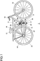
- Fig. 1 schematically illustrates the structure of a motor-assisted bicycle 1, in which the torque sensor achieved in an embodiment of the present invention is installed.
- the motor-assisted bicycle 1 includes a front wheel 12 and a handle bar 13 located on the front side of a frame 11 and a rear wheel 14 located on the rear side of the frame 11.
- a bottom bracket 18 holding bearings is disposed at the bottom end of a seat tube 16, which includes a saddle 15.
- a crankshaft 17 is supported by the bearings at the bottom bracket 18.
- a chain wheel 19 and crank arms 20 are mounted at the crankshaft 17, with pedals 21 attached to the crank arms 20.
- a roller chain 23 is disposed so as to run in a loop between the chain wheel 19 and a sprocket 22 located at the rear wheel 14. The rotation of the crankshaft 17 is transmitted to the rear wheel 14, i.e., the drive wheel via the roller chain 23.
- an assist motor 24 is installed at the motor-assisted bicycle 1. With assistance provided by the motor 24, which rotationally drives a drive sprocket 25 disposed at the crankshaft 17, the amount of pedaling force required from the rider at the pedals 21 can be reduced.
- a torque sensor (not shown) used to measure the torque applied to the crankshaft 17 is installed at the motor-assisted vehicle 1.
- An assist control unit 27 determines an assist quantity, i.e., an extent of assistance to be provided, in correspondence to the measured torque and drives the motor 24 by a degree matching the required assist quantity.
- a battery 26 that provides power to the motor 24 is mounted at the seat tube 16.
- a power supply cable 28 is connected between the assist control unit 27, which executes assist control, and the motor 24.
- a cable 29 for power supply and data signal transmission is connected between the assist control unit 27 and a rotating-side substrate (not shown but will be described in detail later) disposed at the torque sensor.
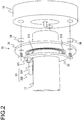
- a torque sensor 30 includes a fixed-side substrate 31, which is fixed to the bottom bracket 18, and a rotating-side substrate 32 and a strain sensor unit 33, both of which are fixed to the crankshaft 17 and rotate as one with the crankshaft 17.
- a bearing unit (not shown) that supports the crankshaft 17 is disposed at the bottom bracket 18.
- the fixed-side substrate 31, which is a substantially ring-shaped member, is screwed to the bottom bracket 18 via spacers 34.
- the crankshaft 17 is inserted through a through hole 311 at the fixed-side substrate 31 with some clearance.
- the rotating-side substrate 32 which is also a substantially ring-shaped member, is fixed to the outer circumferential surface of the crankshaft 17.
- the rotating-side substrate 32 may be fixed by, for instance, locking a substrate holder to the crankshaft 17 and securing the rotating-side substrate 32 to the substrate holder.
- the rotating-side substrate 32 is fixed so that the substrate surface ranges substantially perpendicular to the crankshaft 17.
- the fixed-side substrate 31 and the rotating-side substrate 32 are disposed so as to range substantially parallel to each other via a small clearance between them, and antenna patterns constituted of copper or the like are formed at the surfaces of the fixed-side substrate 31 and the rotating-side substrate 32 facing opposite each other.
- Reference 310 indicates an antenna pattern formed at the fixed-side substrate 31.
- circuit components configuring the torque sensor 30 and wiring patterns connecting the circuit components are disposed at the surfaces of the fixed-side substrate 31 and the rotating-side substrate 32, located on the side opposite from the surfaces where the antenna patterns are formed.
- the spacers 34 mentioned earlier are disposed so as to prevent the circuit components mounted at the fixed-side substrate 31 from coming into contact with the bottom bracket 18.
- the strain sensor unit 33 includes a detection unit 331 stuck to the crankshaft 17 and a flexible cable 332 that connects the detection unit 331 to the rotating-side substrate 32.
- the detection unit 331 includes a built-in A/D converter, and a detected voltage corresponding to the level of strain is converted via the A/D converter to a digital signal, which is then output from the detection unit 331.
- the flexible cable 332 is connected to a connector 321 disposed at the rotating-side substrate 32.
- Fig. 3 presents another example of a mounting structure that may be adopted in conjunction with the torque sensor 30.
- a housing space 182 where the rotating-side substrate 32 and the strain sensor unit 33 are to be housed, is formed at the bottom bracket 18 holding therein a bearing unit 181, which supports the crankshaft 17.
- the crankshaft 17 is mounted at the bearing unit 181, the rotating-side substrate 32 and the strain sensor unit 33 are placed inside the housing space 182.
- the fixed-side substrate 31 is screwed to an end surface of the bottom bracket 18.
- Fig. 4 is a block diagram showing the circuit structure of the torque sensor 30. Electric power is supplied from a power-transmitting unit 410 to a power-receiving unit 420 in Fig. 4 .
- the power-transmitting unit 410 is disposed at the fixed-side substrate 31 in Fig. 2
- the power-receiving unit 420 is disposed at the rotating-side substrate 32.
- the power-transmitting unit 410 and the power-receiving unit 420 configure a non-contact power-feeding device in the torque sensor 30 in Fig. 4 .
- the power-transmitting unit 410 includes an oscillator 411, a power feeding coil 310a and a resonance coil 310b, which configure a power transmitting-side coil, a demodulating circuit 412, a clock (CLK) generating unit 413, a modulating unit 414 and a driver 415.
- the antenna pattern 310 in Fig. 2 is made up with a pattern formed with the power feeding coil 310a and a pattern formed with the resonance coil 310b. It is to be noted that while the coil surfaces of the power feeding coil 310a and the resonance coil 310b, formed as flat-plane windings, face opposite each other in the illustration provided in Fig. 4 , the power feeding coil 310a is actually disposed so as to range within the same plane as the resonance coil 310b on the outer circumferential side thereof, as will be described in detail later.
- the power-receiving unit 420 includes a power receiving-side coil (also referred to as a load coil) 421, a resonance capacitor 422 connected in series to the power receiving-side coil 421, a rectifier circuit 423, a low pass filter 424, a power circuit 425, a load modulating circuit 426, a clock (SCLK) generating unit 427, and an REQ detection unit 428.
- the power receiving-side coil 421 and the resonance capacitor 422 connected in series configure a serial resonance circuit.
- the strain sensor unit 33 is connected to the serial resonance circuit via the rectifier circuit 423 and the power circuit 425. It is to be noted that the power receiving-side coil 421 may assume a single turn or a plurality of turns.
- the low pass filter 424 includes an inductor 424a and a capacitor 424b.
- the load modulating circuit 426 includes a switching element 426a, a capacitor 426b and a resistor 426c.
- a strain data signal (having undergone A/D conversion) provided by the strain sensor unit 33 is input to a gate of the switching element 426a via the resistor 426c in the load modulating circuit 426.
- the resonance frequency adjustment would be complicated, and accordingly, a resonance capacitor is connected to the resonance coil 310b in the embodiment, as will be explained later (see Fig. 9 ).
- the driver 415 feeds power to the power feeding coil 310a.
- Power is fed to the power feeding coil 310a with a frequency (e.g., 16.384 MHz) equal to the self-resonance frequency, which is determined by the self inductance, the stray capacitance manifesting between the coil winding and the resonance capacitance at the resonance coil 310b.
- a frequency e.g., 16.384 MHz
- the intense magnetic field generated via the resonance coil 310b becomes magnetically coupled with the power receiving-side coil 421, thereby generating an electromotive force between the two terminals at the power receiving-side coil 421.
- the electromotive force thus generated is rectified via the rectifier circuit 423 and thus becomes a DC voltage, which is then input to the power circuit 425 via the low pass filter 424.
- the presence of the low pass filter 424 disposed at a stage rearward relative to the rectifier circuit 423 improves the rectification efficiency.
- the power circuit 425 converts the voltage output from the rectifier circuit 423 to a voltage with a predetermined voltage value required by the strain sensor unit 33 and provides the voltage resulting from the conversion to the strain sensor unit 33.
- the torque applied to the crankshaft 17 is detected by detecting strain in the crankshaft with a strain sensor (strain gauge).
- a strain sensor strain gauge
- a torque sensor configured with a strain sensor achieves advantages over a conventional torque sensor configured with, for instance, a magnetostrictive sensor, in that it can be provided as a more compact unit assuring better accuracy and that it can be manufactured at lower cost
- electric power must be supplied to the torque sensor configured with a strain sensor.
- Power must be fed wirelessly to the strain sensor disposed at the rotating side crankshaft, since power feeding via a contact point such as a brush would give rise to concerns such as compromised durability and brush contact noise.
- the power-receiving unit 420 in the embodiment which is disposed at the rotating-side substrate 32, is able to contactlessly receive power transmitted from the power-transmitting unit 410 through magnetic coupling of the power transmitting side resonance coil 310b and the power receiving-side coil 421.
- the power-receiving unit 420 i.e., the rotating-side substrate 32 can be miniaturized.
- strain data from the power-receiving unit 420 to the power-transmitting unit 410 will be explained.
- Data are transmitted in the embodiment by adopting a load modulation method that does not to require much power and allows a simple circuit structure. While a load modulation system is also adopted in IC cards and the like, much stronger coupling between coils is achieved through non-contact power feeding (wireless power feeding) as achieved in the embodiment described above.
- the load modulating circuit 426 is connected at a point H2, located between the rectifier circuit 423 and the low pass filter 424, so as to apply load modulation in the embodiment in which a high level of magnetic coupling strength is achieved.
- a strain data signal is input from the strain sensor unit 33 to the load modulating circuit 426.
- the switching element 426a is engaged in ON/OFF operation in response to the strain data signal.
- This ON/OFF operation causes fluctuation in the impedance on the power receiving side, which changes reflection of the carrier wave (AC magnetic field) from the power-transmitting unit 410. Namely, the amplitude of the carrier wave reflected at the power receiving-side coil 421 fluctuates in correspondence to the impedance fluctuation.
- the power-transmitting unit 410 obtains the strain data by executing demodulation processing on the reflected carrier wave at the demodulation circuit 412.
- the clock (CLK) generating unit 413 generates a clock signal (CLK) by dividing a signal output by the oscillator 411. It may generate, for instance, a 16 kHz clock signal by dividing a 16.384 MHz signal output from the oscillator 411.
- the power-transmitting unit 410 is engaged in operation based upon the clock signal (CLK).
- a clock signal (SCLK) with a frequency matching that of the clock signal (CLK) is generated by dividing, via the clock (SCLK) generating unit 427, an AC signal (carrier wave) received at the power receiving-side coil 421.
- the power-receiving unit 420 is engaged in operation based upon the clock signal (SCLK).
- Strain data are transmitted from the power-receiving unit 420 to the power-transmitting unit 410 based upon a request signal (REQ) provided by the assist control unit 27 shown in Fig. 1 .
- Fig. 5 illustrates how data transmission operation is executed to transmit data between the assist control unit 27 and the power-transmitting unit 410 disposed at the fixed-side substrate 31.
- the strain data (DATA) output from the strain sensor unit 33 stuck to the crankshaft 17 are received, via the power-receiving unit 420 located at the rotating-side substrate 32, at the power-transmitting unit 410 located at the fixed-side substrate 31 and are further transmitted to the assist control unit 27 connected to the fixed-side substrate 31.
- the assist control unit 27 calculates a pedaling force imparted by the rider based upon the strain data transmitted thereto and determines an assist quantity indicating the level of assistance to be provided via the assist motor 24.
- the assist control unit 27 outputs a request signal (REQ) requesting strain data to the power-transmitting unit 410 (falling operation).
- the request signal (REQ) is input to the modulating unit 414 in the power-transmitting unit 410 so as to modulate a power feed signal to be provided to the power feeding coil 310a with the request signal (REQ).
- the amount of transmitted power is altered relative to the pre-modulation state, and accordingly, the change in the amount of transmitted power is detected by the REQ detection unit 428 on the power receiving side so as to use it as a trigger for data transmission.
- a trigger for data transmission is generated by controlling, via the driver 415, the modulating unit 414 to which the request signal (REQ) is input.
- the request signal (REQ) detection unit 428 extracts the request signal (REQ), which is then input to the clock (SCLK) generating unit 427 and the strain sensor unit 33.
- the clock (SCLK) generating unit 427 provides the clock signal (SCLK) to the strain sensor unit 33.
- the A/D converter included in the strain sensor unit 33 is engaged in operation based upon the clock signal (SCLK).
- the strain sensor unit 33 starts output of a strain data signal after a predetermined number of cycles (after four cycles in the example presented in Fig. 5 ) following the rise of the clock signal (SCLK).
- the power-transmitting unit 410 disposed at the fixed-side substrate 31 outputs the strain data (DATA), having been received from the power-receiving unit 420 and demodulated via the demodulating circuit 412 and the clock signal (CLK) synchronous with the clock signal (SCLK), to the assist control unit 27.
- DATA strain data
- CLK clock signal
- the clock may be engaged in operation at all times independently of the request signal (REQ) and in such a case, the clock signal (SCLK) cannot be synchronized with the fall of the request signal (REQ). For this reason, a temporal offset, the extent of which is less than a single cycle of the clock signal (SCLK), may occur with regard to the time elapsing before the data are output following the fall of the request signal (REQ), and under such circumstances, an erroneous operation may occur during data acquisition.
- the clock signal (SCLK) is started with the timing with which the request signal (REQ) falls, and thus, the request signal (REQ) and the clock signal (SCLK) are synchronized with each other.
- the request signal (REQ) and the clock signal (SCLK) are synchronized with each other.
- the cycles of the request signal (REQ) and the cycles of the clock signal (SCLK) in Fig. 5 may be, for instance, 250 ms and 62.5 ⁇ s respectively.
- Fig. 6 presents an example of measures that may be taken at the various terminals at the fixed-side substrate 31 in order to prevent erroneous operation that may occur when external noise or the like is introduced.
- a capacitor 61 with a relatively large capacitance value is used for high-frequency grounding at the power line so as to prevent noise from entering the power line.
- a resistor 62 is inserted in series at the request signal (REQ) line so as to minimize the adverse effect of introduced noise.
- a request signal bias is applied from the power line via a resistor 63 so as to enable the fall of a request signal (REQ) even when the request signal (REQ) is output from the assist control unit 27 in an open drain configuration.
- the clock (CLK) signal terminal and the DATA signal terminal are grounded with capacitors 64 and 65, each achieving an impedance, which is higher relative to the signal frequency and at the same time, sufficiently low relative to any introduced noise.
- resistors 66 and 67 are inserted in series at the lines for the clock (CLK) signal and the DATA signal respectively so as to deter any noise that might otherwise be introduced. While measures against erroneous operation are taken through small-capacitance grounding and insertion of serial resistors in the example presented in Fig. 6 , the present invention is not limited to the example presented in Fig. 6 and measures may be taken through either small-capacitance grounding alone or serial resistor insertion alone.
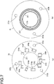
- Fig. 7 shows the fixed-side substrate 31.
- Fig. 7(a) shows the mounting surface at which power transmitting-side circuit components are mounted.
- Fig. 7(b) shows the surface located on the side opposite from the mounting surface shown in Fig. 7(a) , which is a pattern surface where the antenna pattern 310 (see Fig. 2 ) is formed.
- the through hole 311 through which the crankshaft 17 (see Fig. 2 ) passes, is formed at the center of the circular fixed-side substrate 31.
- the through holes 313a, 313b and 313c may be formed at such positions that the plurality of through holes 313a, 313b and 313c are set apart from the center of the through hole 311 (i.e., the centers of the coils 310a and 310b) by distances different from one another. In such a case, the fixed-side substrate 31 can never be locked onto the bottom bracket 18 at the wrong angle.
- Circuit components 316a through 316j are mounted at the mounting surface so as to surround the through hole 311.
- the circuit component 316i is a connector to which the cable 29 shown in Fig. 1 is connected.
- the cable 29 is plugged in/out along the directions indicated by the arrows in the figure.
- the antenna pattern 310 is formed in a hatched area 312 in a ring shape at the fixed-side substrate 31 in Fig. 7(b) .
- the antenna pattern 310 is formed with copper in the ring-shaped area at the fixed-side substrate 31.
- the antenna pattern 310 is made up with the pattern at the power feeding coil 310a and the pattern at the resonance coil 310b.
- a looped ground pattern (GND pattern) 315 is formed so as to range in a full circle around the through hole 311 near the inner edge of the fixed-side substrate 31.
- the crankshaft 17 constituted of metal is inserted through the through hole 311, and thus, the presence of the ground pattern 315 formed as described above makes it possible to reduce the extent to which the antenna pattern 310 (the power feeding coil 310a and the resonance coil 310b) is magnetically affected by the crankshaft 17. It is desirable that the distance between the ground pattern 315, which is a factor that will affect the transmission loss, and the antenna pattern 310 be maximized.
- the wiring pattern connecting the individual circuit components must be laid out by ensuring that it does not form a loop circling the through hole 311, in order to prevent magnetic interference between the wiring pattern and the antenna pattern 310.
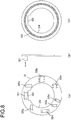
- Fig. 8 shows the rotating-side substrate 32.
- Fig. 8(a) shows the mounting surface at which power receiving-side circuit components are mounted.
- Fig. 8(b) presents a sectional view of the rotating-side substrate 32.
- Fig. 8(c) shows the surface located on the side opposite from the mounting surface shown in Fig. 8(a) , which is a pattern surface where the antenna pattern (the pattern at the power receiving-side coil 421) is formed.
- a through hole 324 through which the crankshaft 17 (see Fig. 2 ) passes, is formed at the center of the rotating-side substrate 32.
- the crankshaft 17 is fitted through the through hole 324, the rotating-side substrate 32 is locked so as to range perpendicular to the crankshaft 17.
- the connector 321 and circuit components 325a through 325g are mounted at the mounting surface so as to surround the through hole 324.
- the connector 321, the circuit components 325a through 325g and a wiring connecting them be disposed so as to keep the level of centrifugal force applied to the rotating-side substrate 32 in balance, i.e., so as to achieve rotational symmetry with regard to the level of centrifugal force.
- the connector 321 allows the flexible cable 332 to be plugged in and out in a direction perpendicular to the substrate surface (along the axis of the crankshaft 17), as illustrated in Fig. 8(b) . This structure makes it possible to prevent the flexible cable 332 from becoming disconnected due to the centrifugal force.
- the antenna pattern at the power receiving-side coil 421 is formed in a hatched area 322 at the pattern-forming surface of the rotating-side substrate 32. It is to be noted that a looped ground pattern is also formed at the rotating-side substrate 32 at a position further inward relative to the hatched area 322, as at the fixed-side substrate 31.
- the wiring pattern connecting the individual circuit components must be laid out by ensuring that it does not form a loop circling the through hole 324, in order to prevent magnetic interference between the wiring pattern and the antenna pattern at the pattern forming surface.
- a notch 323 is formed at the through hole 324 in order to ensure that the detection unit 331 (see Fig. 2 ) fixed to the outer circumferential surface of the crankshaft 17 is not allowed to interfere when the rotating-side substrate 32 is mounted at the crankshaft 17.
- the presence of the notch 323 formed as described above improves the ease of assembly.
- Fig. 9 is a schematic illustration showing in detail the power feeding coil 310a and the resonance coil 310b, which configure the power transmitting-side coil. It is to be noted that Fig. 9 shows the patterns separated from each over a gap wider than the actual gap formed between them so as to provide a clear view of the overall coil pattern.
- the capacitor 317 which is to function as a resonance capacitor, is disposed at the resonance coil 310b.
- the resonance coil 310b is a spiral coil with a plurality of turns.
- the power feeding coil 310a to which the oscillator 411 is connected, forms a pattern further outward relative to the resonance coil 310b.
- the power feeding coil 310a forms a spiral pattern with a plurality of turns (at least two turns).
- the magnetic resonance method assures advantages over the electromagnetic induction method in transmission efficiency, transmission distance, ease of coil alignment and the like.
- the magnetic resonance method further achieves advantages in that the power receiving-side coil can be readily miniaturized, that the extent of interference coupling is lowered (i.e., the effect of noise is reduced), that the extent to which efficiency is lowered by the metal casing and the like can be minimized, and the like.
- the coil is scaled down relative to the transmission frequency (i.e., the self-resonance frequency of the coil), the transmission efficiency tends to be compromised.
- Such a decrease in the transmission efficiency is considered to be attributable to insufficient magnetic coupling with the resonance coil due to a lowered inductance value at the power feeding coil resulting from coil miniaturization.
- the decrease in the transmission efficiency tends to be more pronounced in a torque sensor installed in a motor-assisted bicycle, since the coil diameter in the torque sensor is typically only a few centimeters while the wavelength of the transmission frequency is approximately 10 to 20 m.
- the power feeding coil 310a in the embodiment is disposed further outward relative to the resonance coil 310b and is wound with a plurality of turns, as shown in Fig. 9 , so as to prevent a decrease in the inductance value at the power feeding coil 310a and minimize the extent to which the level of magnetic coupling between the power feeding coil 310a and the resonance coil 310b is lowered.
- the crankshaft 17 constituted of metal is inserted through the through hole 311 formed at the fixed-side substrate 31, the magnetic effect imparted by the crankshaft 17 can be reduced by disposing the power feeding coil 310a further outward, as shown in Fig. 9 , and this positional arrangement is also a contributing factor in minimizing any decrease in the power feeding efficiency.
- the communication band is bound to be narrow.
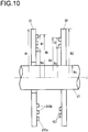
- Fig. 10 is a sectional view illustrating the positional arrangement with which the antenna patterns are disposed.
- the fixed-side substrate 31 and the rotating-side substrate 32 are disposed so that the surfaces thereof at which the antenna patterns are formed face opposite each other. Since power is exchanged and also data are exchanged between the resonance coil 310b and the power receiving-side coil 421 through magnetic coupling achieved by the resonance coil 310b and the power receiving-side coil 421, it is desirable that the distance between the resonance coil 310b and the power receiving-side coil 421 be narrowed for better communication efficiency by disposing the substrates 31 and 32 so that their coil surfaces face opposite each other.
- the fixed-side substrate 31 and the rotating-side substrate 32 are disposed so that their surfaces where the antenna patterns are formed face opposite each other.
- the antenna pattern 310, made up with the patterns of the power feeding coil 310a and the resonance coil 310b is formed at the fixed-side substrate 31, whereas the antenna pattern made up with the pattern of the power receiving-side coil 421 is formed at the rotating-side substrate 32.
- the fixed-side substrate 31 and the rotating-side substrate 32 are disposed so that the centers of the antenna patterns formed at these substrates (i.e., the coil centers) are in alignment with an axis J of the crankshaft 17.
- the exact numbers of turns at the individual patterns are not indicated in Fig. 10 , which simply provides a clear view of the positional arrangement adopted for the antenna patterns.
- Ra represents the inner radius of the resonance coil 310b and Rb represents the outer radius of the power feeding coil 310a disposed further outward relative to the resonance coil 310b at the fixed-side substrate 31, whereas Rc and Rd respectively represent the inner radius and the outer radius of the power receiving-side coil 421 at the rotating-side substrate 32.
- the outer radii of the fixed-side substrate 31 and the rotating-side substrate 32 are respectively represented by R1 and R2. It is to be noted that if the substrates 31 and 32 are not round substrates, the radii R1 and R2 each represent the distance from the center of the corresponding antenna pattern to the closest edge of the particular substrate.
- Ra through Rd should be set so that an area H1 where the power transmitting-side coil is located and an area H2 where the power receiving-side coil is located are not completely offset from each other along the radial direction with at least portions thereof facing opposite each other. It is even more desirable that the average radius of the resonance coil 310b located on the power transmitting-side be set equal to the average radius of the power receiving-side coil 421.
- Fig. 11 presents diagrams indicating the relationship between an antenna pattern and transmission characteristics.
- Fig. 11(a) is a graph providing the results obtained by simulating the relationship between the line width of an antenna pattern and the transmission characteristics
- Fig. 11(b) provides a schematic illustration of an antenna pattern.
- P represents the pitch of adjacent pattern line portions in the pattern
- W represents the pattern line width measurement. It is to be noted that the ratio of the pattern line width W to the pitch P (W/P) is indicated along the horizontal axis in Fig. 11(a) . The following description will be given by assuming that the pitch P remains constant at 3 mm.
- Fig. 12 shows the strain sensor unit 33, with Fig. 12(a) showing it in a plan view and Fig. 12(b) presenting a sectional view taken along C-C.
- a sensor chip 333 with a built-in strain gauge is stuck to a thin metal plate (e.g., stainless steel sheet) 334.
- a circuit needed for strain measurement, an A/D converter that converts a strain quantity signal to a digital signal, and the like are built into the sensor chip 333.
- One end of the flexible cable 332 is fixed to the metal plate 334 and the sensor chip 333 and a wiring pattern (not shown) for the flexible cable 332 are connected via a wire 335.
- the sensor chip 333, the wire 335 and the wire connector portion of the flexible cable 332 are molded with a sealing resin 338.
- the sealing resin 338 is simply indicated with an imaginary line (two-point chain line) so as to indicate the positional arrangement and the like assumed at the chip.
- the rear surface of the metal plate 334 is stuck to the surface of the crankshaft 17, i.e., the strain measurement target.
- the metal plate 334 in the detection unit 331 is fixed to a portion of the outer circumferential surface of the crankshaft 17 that has been machined so as to achieve a flat surface.
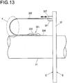
- Fig. 13 illustrates a connection mode that is adopted when connecting the flexible cable 332 to the rotating-side substrate 32 in a side view of the crankshaft 17, to which the detection unit 331 in the strain sensor unit 33 is fixed, and the rotating-side substrate 32.
- the rotating-side substrate 32 is mounted so that the substrate surface ranges perpendicular to the crankshaft 17.
- the connector 321, to which the connector portion 337 of the flexible cable 332 is connected, is disposed at the rotating-side substrate 32.
- the connector 321 is mounted at the rotating-side substrate 32 so that the connector portion 337 of the flexible cable 332 is plugged in and out along the directions running parallel to the crankshaft 17.
- the surface indicated by the letter D is the surface where the antenna pattern is formed, whereas the surface indicated by the letter E is the surface where the circuit components are mounted.
- the detection unit 331 is stuck to the crankshaft 17 so that the flexible cable 332 is led out from the detection unit 331 along the direction running away from the circuit component mounting surface E of the rotating-side substrate 32.
- the flexible cable 332 led out from the detection unit 331 is then bent so as to form a circular arc and ran toward the circuit component mounting surface E and is connected to the connector 321 at the rotating-side substrate 32.
- the rotating body non-contact power-feeding device achieved in the embodiment described above includes the rotating-side substrate 32 with power receiving-side circuit components disposed thereat, which is fixed to the crankshaft 17 supported by the bearing unit 181 and rotates as one with the crankshaft 17, and the fixed-side substrate 31 with power transmitting-side circuit components mounted thereat, which is fixed to the bottom bracket 18 holding the bearing unit 181 so that the substrate surface of the fixed-side substrate faces opposite the substrate surface of the rotating-side substrate 32 and is connected with a power source.
- a spiral power transmitting-side coil (configured with the power feeding coil 310a and the resonance coil 310b) having a plurality of turns is formed with a conductive pattern at one of these substrate surfaces, which faces opposite the rotating-side substrate 32, with the power transmitting-side circuit components mounted at the other substrate surface.
- the rotating-side substrate 32 includes a substrate front surface and a substrate back surface
- a spiral power receiving-side coil 421 with a plurality of turns is formed with a conductive pattern at a substrate surface that faces opposite the fixed-side substrate 31 with the power receiving-side circuit components mounted at the other substrate surface.
- the coils 310a, 310b and 421 are formed with coil patterns at the substrate surfaces of the substrates 31 and 32 and the resonance coil 310b located on the power transmitting side and the power receiving-side coil 421 are set so as to face opposite each other, resulting in a compact non-contact power-feeding device assuring outstanding power feeding efficiency.
- the power transmitting side antenna coil be configured with a flat-plane spiral resonance coil 310b having a plurality of turns and a flat-plane spiral power feeding coil 310a having a plurality of turns, disposed further outward relative to the resonance coil 310b so as to surround the resonance coil 310b, which is magnetically coupled with the resonance coil 310b. Since this configuration makes it possible to ensure that sufficient inductance is achieved at the power feeding coil 310a, a satisfactory level of power feeding efficiency can be assured even if the power transmitting-side coil is miniaturized.
- the power receiving-side coil is configured with a single power receiving-side coil 421 in the embodiment described above, it may instead be configured with two coils (a resonance coil and a load coil, to which the rectifier circuit 423 is connected) as on the power transmitting side, or the power transmitting-side coil and the power receiving-side coil may each be configured with a single coil such as the power receiving-side coil 421 explained above.
- the load circuit in the embodiment described above is configured with the strain sensor unit 33, which includes a strain gauge
- the present invention may instead be adopted in conjunction with a load circuit configured with a temperature sensor circuit, an acceleration sensor circuit or the like instead of a strain sensor circuit.
- the torque sensor achieved in the embodiment may instead be used to measure torque applied to another rotating shaft or another rotating body.
- a rotating-side substrate in a disk shape may be fixed to an end surface of the rotating shaft and a fixed-side substrate in a disk shape may be fixed to a member that holds a bearing.
- the present invention teaching a technology for contactlessly feeding power to a circuit or a sensor mounted at a rotating body such as, for instance, a shaft, and contactlessly extracting data from a rotating body sensor, may be adopted in contactless power feeding to a strain gauge or a strain sensor used to detect torque in an automobile drive train or to detect pedaling force in a motor-assisted bicycle, and in contactless data transmission. It may be further adopted in a non-contact power-feeding device in which the positional relationship between the power receiving-side coil and the power transmitting-side coil is not fixed, e.g., in a configuration in which a power receiving side IC card is moved closer to the fixed power transmitting side for purposes of power feed.
- power-receiving unit 421 ... power receiving-side coil, 422 ... resonance capacitor, 423 ... rectifier circuit, 424 ... low pass filter, 425 ... power circuit, 426 ... load modulating circuit, 427 ... clock (SCLK) generating unit, 428 ... request signal (REQ) detection unit
Landscapes
- Engineering & Computer Science (AREA)
- Power Engineering (AREA)
- Physics & Mathematics (AREA)
- Computer Networks & Wireless Communication (AREA)
- General Physics & Mathematics (AREA)
- Electromagnetism (AREA)
- Arrangements For Transmission Of Measured Signals (AREA)
Abstract
Description
- The present invention relates to a non-contact power-feeding device and a torque sensor.
- In a motor-assisted bicycle in the related art, the rotational torque applied to a crankshaft of the bicycle is detected through a non-contact means and the drive force imparted by a motor is used to assist the rider with pedaling. The rotational torque may be detected with, for instance, a magnetostrictive torque sensor having a magnetostrictive detection layer that is rendered magnetically anisotropic, formed at an outer circumferential surface or the like of the crankshaft, and a coil disposed on the outer circumferential side of the magnetostrictive detection layer with a predetermined gap formed between them (see PTL1).
- In addition, in a standard torque measuring method known in the related art, torque applied to a rotating shaft is measured via a strain sensor, which measures the torque applied to the rotating shaft by measuring the extent of strain at the rotating shaft with a strain gauge.
- PTL1: Japanese Laid Open Patent Publication No.
H09-95289 - A torque sensor configured with a strain gauge has advantages over a magnetostrictive torque sensor in that it can be provided as a more compact unit assuring better accuracy and that it can be manufactured at lower cost. However, the strain gauge torque sensor requires a non-contact power-feeding device capable of wireless power feeding in order to supply power to the strain gauge mounted at the rotating shaft. In addition, data must be wirelessly transmitted from the strain gauge mounted at the rotating shaft.
- Furthermore, since wireless power feeding is achieved in conjunction with a power receiving-side coil disposed at the crankshaft of the motor-assisted bicycle, miniaturization of the torque sensor needs to be pursued while assuring a high level of power feeding efficiency.
- According to an aspect of the present invention, a non-contact power-feeding device comprises: a power transmitting unit that includes a first antenna coil, an oscillator and a driver that enables generation of an AC magnetic field via the first antenna coil based upon a signal provided by the oscillator; and a power receiving unit that includes a second antenna coil that is magnetically coupled with the first antenna coil, wherein the first antenna coil comprises: a flat-plane spiral resonance coil wound with a plurality of turns; and a flat-plane spiral power-feeding coil that is wound with a plurality of turns outward relative to the resonance coil so as to surround the resonance coil, and is magnetically coupled with the resonance coil.
- According to the present invention, the magnetic coupling achieved via the power-feeding coil and the resonance coil configuring the antenna coil in the power transmitting unit can be further strengthened and as a result, a compact non-contact power-feeding device assuring outstanding power-feeding efficiency and a torque sensor equipped with the non-contact power-feeding device can be provided.
-
- [
Fig. 1 ] An illustration of the torque sensor achieved in an embodiment of the present invention - [
Fig. 2 ] A perspective showing the overall structure of the torque sensor - [
Fig. 3 ] Another example of a mounting structure that may be adopted for the torque sensor - [
Fig. 4 ] A block diagram showing the circuit structure of the torque sensor - [
Fig. 5 ] Diagrams illustrating how data are exchanged between theassist control unit 27 and the power-transmittingunit 410 disposed at the fixed-side substrate 31 - [
Fig. 6 ] An example of measures that may be taken at the various terminals on the fixed-side substrate 31 in order to prevent erroneous operation that may readily occur due to introduced noise or the like - [
Fig. 7 ] Illustrations of the fixed-side substrate 31 - [
Fig. 8 ] Illustrations of the rotating-side substrate 32 - [
Fig. 9 ] A schematic illustration showing in detail thepower feeding coil 310a and theresonance coil 310b configuring a power transmitting-side coil - [
Fig. 10 ] A sectional view illustrating the positional arrangement adopted for the antenna patterns - [
Fig. 11 ] Diagrams indicating the relationship between an antenna pattern and transmission characteristics - [
Fig. 12 ] Illustrations of thestrain sensor unit 33 - [
Fig. 13 ] A diagram illustrating the connection mode adopted for connection of theflexible cable 332 to the rotating-side substrate 32 - The following is a description of an embodiment of the present invention, given in reference to drawings.
Fig. 1 schematically illustrates the structure of a motor-assistedbicycle 1, in which the torque sensor achieved in an embodiment of the present invention is installed. - The motor-assisted
bicycle 1 includes afront wheel 12 and ahandle bar 13 located on the front side of aframe 11 and arear wheel 14 located on the rear side of theframe 11. Abottom bracket 18 holding bearings, is disposed at the bottom end of aseat tube 16, which includes asaddle 15. Acrankshaft 17 is supported by the bearings at thebottom bracket 18. Achain wheel 19 andcrank arms 20 are mounted at thecrankshaft 17, withpedals 21 attached to thecrank arms 20. Aroller chain 23 is disposed so as to run in a loop between thechain wheel 19 and asprocket 22 located at therear wheel 14. The rotation of thecrankshaft 17 is transmitted to therear wheel 14, i.e., the drive wheel via theroller chain 23. - In addition, an
assist motor 24 is installed at the motor-assistedbicycle 1. With assistance provided by themotor 24, which rotationally drives adrive sprocket 25 disposed at thecrankshaft 17, the amount of pedaling force required from the rider at thepedals 21 can be reduced. As will be described later, a torque sensor (not shown) used to measure the torque applied to thecrankshaft 17 is installed at the motor-assistedvehicle 1. Anassist control unit 27 determines an assist quantity, i.e., an extent of assistance to be provided, in correspondence to the measured torque and drives themotor 24 by a degree matching the required assist quantity. - A
battery 26 that provides power to themotor 24 is mounted at theseat tube 16. Apower supply cable 28 is connected between theassist control unit 27, which executes assist control, and themotor 24. In addition, acable 29 for power supply and data signal transmission is connected between theassist control unit 27 and a rotating-side substrate (not shown but will be described in detail later) disposed at the torque sensor. -
Fig. 2 shows the overall structure of the torque sensor in a perspective. Atorque sensor 30 includes a fixed-side substrate 31, which is fixed to thebottom bracket 18, and a rotating-side substrate 32 and astrain sensor unit 33, both of which are fixed to thecrankshaft 17 and rotate as one with thecrankshaft 17. A bearing unit (not shown) that supports thecrankshaft 17 is disposed at thebottom bracket 18. The fixed-side substrate 31, which is a substantially ring-shaped member, is screwed to thebottom bracket 18 viaspacers 34. Thecrankshaft 17 is inserted through athrough hole 311 at the fixed-side substrate 31 with some clearance. The rotating-side substrate 32, which is also a substantially ring-shaped member, is fixed to the outer circumferential surface of thecrankshaft 17. The rotating-side substrate 32 may be fixed by, for instance, locking a substrate holder to thecrankshaft 17 and securing the rotating-side substrate 32 to the substrate holder. - The rotating-
side substrate 32 is fixed so that the substrate surface ranges substantially perpendicular to thecrankshaft 17. The fixed-side substrate 31 and the rotating-side substrate 32 are disposed so as to range substantially parallel to each other via a small clearance between them, and antenna patterns constituted of copper or the like are formed at the surfaces of the fixed-side substrate 31 and the rotating-side substrate 32 facing opposite each other.Reference 310 indicates an antenna pattern formed at the fixed-side substrate 31. At the surfaces of the fixed-side substrate 31 and the rotating-side substrate 32, located on the side opposite from the surfaces where the antenna patterns are formed, circuit components configuring thetorque sensor 30 and wiring patterns connecting the circuit components are disposed. Thespacers 34 mentioned earlier are disposed so as to prevent the circuit components mounted at the fixed-side substrate 31 from coming into contact with thebottom bracket 18. - The
strain sensor unit 33 includes adetection unit 331 stuck to thecrankshaft 17 and aflexible cable 332 that connects thedetection unit 331 to the rotating-side substrate 32. Thedetection unit 331 includes a built-in A/D converter, and a detected voltage corresponding to the level of strain is converted via the A/D converter to a digital signal, which is then output from thedetection unit 331. Theflexible cable 332 is connected to aconnector 321 disposed at the rotating-side substrate 32. -
Fig. 3 presents another example of a mounting structure that may be adopted in conjunction with thetorque sensor 30. In the example presented inFig. 3 , ahousing space 182, where the rotating-side substrate 32 and thestrain sensor unit 33 are to be housed, is formed at thebottom bracket 18 holding therein abearing unit 181, which supports thecrankshaft 17. As thecrankshaft 17 is mounted at thebearing unit 181, the rotating-side substrate 32 and thestrain sensor unit 33 are placed inside thehousing space 182. The fixed-side substrate 31 is screwed to an end surface of thebottom bracket 18. -
Fig. 4 is a block diagram showing the circuit structure of thetorque sensor 30. Electric power is supplied from a power-transmittingunit 410 to a power-receivingunit 420 inFig. 4 . The power-transmittingunit 410 is disposed at the fixed-side substrate 31 inFig. 2 , whereas the power-receivingunit 420 is disposed at the rotating-side substrate 32. The power-transmittingunit 410 and the power-receivingunit 420 configure a non-contact power-feeding device in thetorque sensor 30 inFig. 4 . - The power-transmitting
unit 410 includes anoscillator 411, apower feeding coil 310a and aresonance coil 310b, which configure a power transmitting-side coil, ademodulating circuit 412, a clock (CLK)generating unit 413, a modulatingunit 414 and adriver 415. Theantenna pattern 310 inFig. 2 is made up with a pattern formed with thepower feeding coil 310a and a pattern formed with theresonance coil 310b. It is to be noted that while the coil surfaces of thepower feeding coil 310a and theresonance coil 310b, formed as flat-plane windings, face opposite each other in the illustration provided inFig. 4 , thepower feeding coil 310a is actually disposed so as to range within the same plane as theresonance coil 310b on the outer circumferential side thereof, as will be described in detail later. - The power-receiving
unit 420 includes a power receiving-side coil (also referred to as a load coil) 421, aresonance capacitor 422 connected in series to the power receiving-side coil 421, a rectifier circuit 423, alow pass filter 424, apower circuit 425, aload modulating circuit 426, a clock (SCLK)generating unit 427, and anREQ detection unit 428. The power receiving-side coil 421 and theresonance capacitor 422 connected in series configure a serial resonance circuit. Thestrain sensor unit 33 is connected to the serial resonance circuit via the rectifier circuit 423 and thepower circuit 425. It is to be noted that the power receiving-side coil 421 may assume a single turn or a plurality of turns. - The
low pass filter 424 includes aninductor 424a and acapacitor 424b. Theload modulating circuit 426 includes aswitching element 426a, acapacitor 426b and aresistor 426c. A strain data signal (having undergone A/D conversion) provided by thestrain sensor unit 33 is input to a gate of theswitching element 426a via theresistor 426c in theload modulating circuit 426. - If the capacitive component of the resonance at the
resonance coil 310b were entirely accounted for by the stray capacitance (parasitic capacitance) manifesting between the winding line portions of the coil, the resonance frequency adjustment would be complicated, and accordingly, a resonance capacitor is connected to theresonance coil 310b in the embodiment, as will be explained later (seeFig. 9 ). Based upon a signal provided by theoscillator 411, thedriver 415 feeds power to the power feeding coil 310a. Power is fed to thepower feeding coil 310a with a frequency (e.g., 16.384 MHz) equal to the self-resonance frequency, which is determined by the self inductance, the stray capacitance manifesting between the coil winding and the resonance capacitance at theresonance coil 310b. - As the
resonance coil 310b is excited with a frequency equal to the self-resonance frequency through an electromagnetic induction effect, a large current flows through theresonance coil 310b, thereby generating an intense magnetic field. The self-resonance frequency f of the coil may be calculated as expressed in (1) below with L representing the inductance value at theresonance coil 310b and C representing the capacitance (including the capacitance of the resonance capacitor) at theresonance coil 310b.
- When the power receiving-
side coil 421 of the power-receivingunit 420 is disposed in close proximity to theresonance coil 310b, the intense magnetic field generated via theresonance coil 310b becomes magnetically coupled with the power receiving-side coil 421, thereby generating an electromotive force between the two terminals at the power receiving-side coil 421. The electromotive force thus generated is rectified via the rectifier circuit 423 and thus becomes a DC voltage, which is then input to thepower circuit 425 via thelow pass filter 424. The presence of thelow pass filter 424 disposed at a stage rearward relative to the rectifier circuit 423 improves the rectification efficiency. Thepower circuit 425 converts the voltage output from the rectifier circuit 423 to a voltage with a predetermined voltage value required by thestrain sensor unit 33 and provides the voltage resulting from the conversion to thestrain sensor unit 33. - In the embodiment, the torque applied to the
crankshaft 17 is detected by detecting strain in the crankshaft with a strain sensor (strain gauge). While a torque sensor configured with a strain sensor achieves advantages over a conventional torque sensor configured with, for instance, a magnetostrictive sensor, in that it can be provided as a more compact unit assuring better accuracy and that it can be manufactured at lower cost, electric power must be supplied to the torque sensor configured with a strain sensor. Power must be fed wirelessly to the strain sensor disposed at the rotating side crankshaft, since power feeding via a contact point such as a brush would give rise to concerns such as compromised durability and brush contact noise. - As described earlier, the power-receiving
unit 420 in the embodiment, which is disposed at the rotating-side substrate 32, is able to contactlessly receive power transmitted from the power-transmittingunit 410 through magnetic coupling of the power transmittingside resonance coil 310b and the power receiving-side coil 421. In addition, since power can be received on the power receiving side with the power receiving-side coil 421 alone, the power-receivingunit 420, i.e., the rotating-side substrate 32 can be miniaturized. - Next, transmission of strain data from the power-receiving
unit 420 to the power-transmittingunit 410 will be explained. Data are transmitted in the embodiment by adopting a load modulation method that does not to require much power and allows a simple circuit structure. While a load modulation system is also adopted in IC cards and the like, much stronger coupling between coils is achieved through non-contact power feeding (wireless power feeding) as achieved in the embodiment described above. - While the load modulating circuit is connected at a point H1 indicated by the two-point chain line in
Fig. 4 in the related art, high coupling strength gives rise to a problem in that a greater fluctuation in the impedance attributable to fluctuation in the distance between thesubstrates coils crankshaft 17 located near the antenna patterns and the like leads to a significant change in the degree of load modulation. A greater degree of modulation may result in a significant drop in the power feeding efficiency, which could even disable circuit operation at the power-receivingunit 420. - Accordingly, instead of the positional arrangement in the related art, which functions well enough as long as the level of magnetic coupling strength remains relatively low, the
load modulating circuit 426 is connected at a point H2, located between the rectifier circuit 423 and thelow pass filter 424, so as to apply load modulation in the embodiment in which a high level of magnetic coupling strength is achieved. In order to transmit strain data from the power-receivingunit 420 to the power-transmittingunit 410, a strain data signal is input from thestrain sensor unit 33 to theload modulating circuit 426. Theswitching element 426a is engaged in ON/OFF operation in response to the strain data signal. This ON/OFF operation causes fluctuation in the impedance on the power receiving side, which changes reflection of the carrier wave (AC magnetic field) from the power-transmittingunit 410. Namely, the amplitude of the carrier wave reflected at the power receiving-side coil 421 fluctuates in correspondence to the impedance fluctuation. The power-transmittingunit 410 obtains the strain data by executing demodulation processing on the reflected carrier wave at thedemodulation circuit 412. - By connecting the
load modulating circuit 426 at the point H2 instead of at the point H1 as in the related art, impedance fluctuations attributable to load modulation can be better suppressed, due to the presence of the rectifier circuit 423 disposed between theload modulating circuit 426 and the power receiving-side coil 421. As a result, the degree of modulation does not become excessively high and thus, any significant decrease in the power feeding efficiency is prevented even in the embodiment in which high magnetic coupling strength is achieved. - Next, the method adopted to achieve data transmission synchronization will be explained. The clock (CLK)
generating unit 413 generates a clock signal (CLK) by dividing a signal output by theoscillator 411. It may generate, for instance, a 16 kHz clock signal by dividing a 16.384 MHz signal output from theoscillator 411. The power-transmittingunit 410 is engaged in operation based upon the clock signal (CLK). At the power-receivingunit 420, a clock signal (SCLK) with a frequency matching that of the clock signal (CLK) is generated by dividing, via the clock (SCLK)generating unit 427, an AC signal (carrier wave) received at the power receiving-side coil 421. The power-receivingunit 420 is engaged in operation based upon the clock signal (SCLK). - Strain data are transmitted from the power-receiving
unit 420 to the power-transmittingunit 410 based upon a request signal (REQ) provided by theassist control unit 27 shown inFig. 1 .Fig. 5 illustrates how data transmission operation is executed to transmit data between theassist control unit 27 and the power-transmittingunit 410 disposed at the fixed-side substrate 31. The strain data (DATA) output from thestrain sensor unit 33 stuck to thecrankshaft 17 are received, via the power-receivingunit 420 located at the rotating-side substrate 32, at the power-transmittingunit 410 located at the fixed-side substrate 31 and are further transmitted to the assistcontrol unit 27 connected to the fixed-side substrate 31. Theassist control unit 27 calculates a pedaling force imparted by the rider based upon the strain data transmitted thereto and determines an assist quantity indicating the level of assistance to be provided via theassist motor 24. - As indicated in
Fig. 5(a) , theassist control unit 27 outputs a request signal (REQ) requesting strain data to the power-transmitting unit 410 (falling operation). As shown inFig. 4 , the request signal (REQ) is input to themodulating unit 414 in the power-transmittingunit 410 so as to modulate a power feed signal to be provided to thepower feeding coil 310a with the request signal (REQ). Through this modulation, the amount of transmitted power is altered relative to the pre-modulation state, and accordingly, the change in the amount of transmitted power is detected by theREQ detection unit 428 on the power receiving side so as to use it as a trigger for data transmission. Namely, a trigger for data transmission is generated by controlling, via thedriver 415, the modulatingunit 414 to which the request signal (REQ) is input. - At the power-receiving
unit 420 having received the AC signal modulated by using the request signal (REQ), the request signal (REQ)detection unit 428 extracts the request signal (REQ), which is then input to the clock (SCLK)generating unit 427 and thestrain sensor unit 33. In synchronization with the fall of the request signal (REQ), the clock (SCLK)generating unit 427 provides the clock signal (SCLK) to thestrain sensor unit 33. The A/D converter included in thestrain sensor unit 33 is engaged in operation based upon the clock signal (SCLK). Thestrain sensor unit 33 starts output of a strain data signal after a predetermined number of cycles (after four cycles in the example presented inFig. 5 ) following the rise of the clock signal (SCLK). - The power-transmitting
unit 410 disposed at the fixed-side substrate 31 outputs the strain data (DATA), having been received from the power-receivingunit 420 and demodulated via thedemodulating circuit 412 and the clock signal (CLK) synchronous with the clock signal (SCLK), to the assistcontrol unit 27. - Unlike in the embodiment described above, in which the clock signal (SCLK) is started in synchronization with the fall of the request signal (REQ), the clock may be engaged in operation at all times independently of the request signal (REQ) and in such a case, the clock signal (SCLK) cannot be synchronized with the fall of the request signal (REQ). For this reason, a temporal offset, the extent of which is less than a single cycle of the clock signal (SCLK), may occur with regard to the time elapsing before the data are output following the fall of the request signal (REQ), and under such circumstances, an erroneous operation may occur during data acquisition.
- In the embodiment, the clock signal (SCLK) is started with the timing with which the request signal (REQ) falls, and thus, the request signal (REQ) and the clock signal (SCLK) are synchronized with each other. As a result, an improvement is achieved with regard to the temporal offset that occurs before the data are output following the fall of the request signal (REQ).
- It is to be noted that the cycles of the request signal (REQ) and the cycles of the clock signal (SCLK) in
Fig. 5 may be, for instance, 250 ms and 62.5 µs respectively. -
Fig. 6 presents an example of measures that may be taken at the various terminals at the fixed-side substrate 31 in order to prevent erroneous operation that may occur when external noise or the like is introduced. Acapacitor 61 with a relatively large capacitance value is used for high-frequency grounding at the power line so as to prevent noise from entering the power line. In addition, aresistor 62 is inserted in series at the request signal (REQ) line so as to minimize the adverse effect of introduced noise. It is to be noted that a request signal bias is applied from the power line via aresistor 63 so as to enable the fall of a request signal (REQ) even when the request signal (REQ) is output from theassist control unit 27 in an open drain configuration. - In addition, the clock (CLK) signal terminal and the DATA signal terminal are grounded with
capacitors resistors Fig. 6 , the present invention is not limited to the example presented inFig. 6 and measures may be taken through either small-capacitance grounding alone or serial resistor insertion alone. -
Fig. 7 shows the fixed-side substrate 31.Fig. 7(a) shows the mounting surface at which power transmitting-side circuit components are mounted.Fig. 7(b) shows the surface located on the side opposite from the mounting surface shown inFig. 7(a) , which is a pattern surface where the antenna pattern 310 (seeFig. 2 ) is formed. - As shown in
Fig. 7(a) , the throughhole 311, through which the crankshaft 17 (seeFig. 2 ) passes, is formed at the center of the circular fixed-side substrate 31. Toward the outer edge of the fixed-side substrate 31, throughholes holes holes coils side substrate 31 can never be locked onto thebottom bracket 18 at the wrong angle. -
Circuit components 316a through 316j are mounted at the mounting surface so as to surround the throughhole 311. Thecircuit component 316i is a connector to which thecable 29 shown inFig. 1 is connected. Thecable 29 is plugged in/out along the directions indicated by the arrows in the figure. - The
antenna pattern 310 is formed in a hatchedarea 312 in a ring shape at the fixed-side substrate 31 inFig. 7(b) . Theantenna pattern 310 is formed with copper in the ring-shaped area at the fixed-side substrate 31. As explained earlier (seeFig. 4 ), theantenna pattern 310 is made up with the pattern at thepower feeding coil 310a and the pattern at theresonance coil 310b. - In addition, a looped ground pattern (GND pattern) 315 is formed so as to range in a full circle around the through
hole 311 near the inner edge of the fixed-side substrate 31. As shown inFig. 2 , thecrankshaft 17 constituted of metal is inserted through the throughhole 311, and thus, the presence of theground pattern 315 formed as described above makes it possible to reduce the extent to which the antenna pattern 310 (thepower feeding coil 310a and theresonance coil 310b) is magnetically affected by thecrankshaft 17. It is desirable that the distance between theground pattern 315, which is a factor that will affect the transmission loss, and theantenna pattern 310 be maximized. In addition, the wiring pattern connecting the individual circuit components must be laid out by ensuring that it does not form a loop circling the throughhole 311, in order to prevent magnetic interference between the wiring pattern and theantenna pattern 310. -
Fig. 8 shows the rotating-side substrate 32.Fig. 8(a) shows the mounting surface at which power receiving-side circuit components are mounted.Fig. 8(b) presents a sectional view of the rotating-side substrate 32.Fig. 8(c) shows the surface located on the side opposite from the mounting surface shown inFig. 8(a) , which is a pattern surface where the antenna pattern (the pattern at the power receiving-side coil 421) is formed. - As shown in
Fig. 8(a) , a throughhole 324, through which the crankshaft 17 (seeFig. 2 ) passes, is formed at the center of the rotating-side substrate 32. As thecrankshaft 17 is fitted through the throughhole 324, the rotating-side substrate 32 is locked so as to range perpendicular to thecrankshaft 17. Theconnector 321 andcircuit components 325a through 325g are mounted at the mounting surface so as to surround the throughhole 324. Since the rotating-side substrate 32 rotates as one with thecrankshaft 17, it is desirable that theconnector 321, thecircuit components 325a through 325g and a wiring connecting them be disposed so as to keep the level of centrifugal force applied to the rotating-side substrate 32 in balance, i.e., so as to achieve rotational symmetry with regard to the level of centrifugal force. In addition, theconnector 321 allows theflexible cable 332 to be plugged in and out in a direction perpendicular to the substrate surface (along the axis of the crankshaft 17), as illustrated inFig. 8(b) . This structure makes it possible to prevent theflexible cable 332 from becoming disconnected due to the centrifugal force. - The antenna pattern at the power receiving-
side coil 421 is formed in a hatchedarea 322 at the pattern-forming surface of the rotating-side substrate 32. It is to be noted that a looped ground pattern is also formed at the rotating-side substrate 32 at a position further inward relative to the hatchedarea 322, as at the fixed-side substrate 31. In addition, the wiring pattern connecting the individual circuit components must be laid out by ensuring that it does not form a loop circling the throughhole 324, in order to prevent magnetic interference between the wiring pattern and the antenna pattern at the pattern forming surface. - It is to be noted that a
notch 323 is formed at the throughhole 324 in order to ensure that the detection unit 331 (seeFig. 2 ) fixed to the outer circumferential surface of thecrankshaft 17 is not allowed to interfere when the rotating-side substrate 32 is mounted at thecrankshaft 17. The presence of thenotch 323 formed as described above improves the ease of assembly. -
Fig. 9 is a schematic illustration showing in detail thepower feeding coil 310a and theresonance coil 310b, which configure the power transmitting-side coil. It is to be noted thatFig. 9 shows the patterns separated from each over a gap wider than the actual gap formed between them so as to provide a clear view of the overall coil pattern. As explained earlier, thecapacitor 317, which is to function as a resonance capacitor, is disposed at theresonance coil 310b. Theresonance coil 310b is a spiral coil with a plurality of turns. Thepower feeding coil 310a, to which theoscillator 411 is connected, forms a pattern further outward relative to theresonance coil 310b. Thepower feeding coil 310a forms a spiral pattern with a plurality of turns (at least two turns). - While magnetic resonance coils are used in the embodiment, the magnetic resonance method assures advantages over the electromagnetic induction method in transmission efficiency, transmission distance, ease of coil alignment and the like. The magnetic resonance method further achieves advantages in that the power receiving-side coil can be readily miniaturized, that the extent of interference coupling is lowered (i.e., the effect of noise is reduced), that the extent to which efficiency is lowered by the metal casing and the like can be minimized, and the like. However, if the coil is scaled down relative to the transmission frequency (i.e., the self-resonance frequency of the coil), the transmission efficiency tends to be compromised. Such a decrease in the transmission efficiency is considered to be attributable to insufficient magnetic coupling with the resonance coil due to a lowered inductance value at the power feeding coil resulting from coil miniaturization. The decrease in the transmission efficiency tends to be more pronounced in a torque sensor installed in a motor-assisted bicycle, since the coil diameter in the torque sensor is typically only a few centimeters while the wavelength of the transmission frequency is approximately 10 to 20 m.
- Accordingly, the
power feeding coil 310a in the embodiment is disposed further outward relative to theresonance coil 310b and is wound with a plurality of turns, as shown inFig. 9 , so as to prevent a decrease in the inductance value at thepower feeding coil 310a and minimize the extent to which the level of magnetic coupling between thepower feeding coil 310a and theresonance coil 310b is lowered. In addition, while thecrankshaft 17 constituted of metal is inserted through the throughhole 311 formed at the fixed-side substrate 31, the magnetic effect imparted by thecrankshaft 17 can be reduced by disposing thepower feeding coil 310a further outward, as shown inFig. 9 , and this positional arrangement is also a contributing factor in minimizing any decrease in the power feeding efficiency. - Furthermore, by disposing the
resonance coil 310b and the power receiving-side coil 421 so that their coil surfaces face opposite each other, effective magnetic coupling is achieved, which, in turn, improves the transmission efficiency. Moreover, in consideration of the effect of noise on data transmission, the magnetic resonance method, achieving a greater Q value (= fθ/BW, fθ: central frequency, BW: bandwidth of -3dB relative to the gain of the central frequency fθ) assures better transmission efficiency and is not readily subject to the influence of noise. However, when a large value is taken for the Q value, the communication band is bound to be narrow. For this reason, it is desirable that a greater value be taken for the Q value at the power receiving-side coil 421 located on the data transmission side than the value taken for the Q value at theresonance coil 310b located on the data reception side in the embodiment in which the strain data are transmitted from the rotating-side substrate 32 to the fixed-side substrate 31. -
Fig. 10 is a sectional view illustrating the positional arrangement with which the antenna patterns are disposed. As explained earlier (seeFig. 2 ), the fixed-side substrate 31 and the rotating-side substrate 32 are disposed so that the surfaces thereof at which the antenna patterns are formed face opposite each other. Since power is exchanged and also data are exchanged between theresonance coil 310b and the power receiving-side coil 421 through magnetic coupling achieved by theresonance coil 310b and the power receiving-side coil 421, it is desirable that the distance between theresonance coil 310b and the power receiving-side coil 421 be narrowed for better communication efficiency by disposing thesubstrates side substrate 31 and the rotating-side substrate 32 are disposed so that their surfaces where the antenna patterns are formed face opposite each other. Theantenna pattern 310, made up with the patterns of thepower feeding coil 310a and theresonance coil 310b is formed at the fixed-side substrate 31, whereas the antenna pattern made up with the pattern of the power receiving-side coil 421 is formed at the rotating-side substrate 32. - It is to be noted that the fixed-
side substrate 31 and the rotating-side substrate 32 are disposed so that the centers of the antenna patterns formed at these substrates (i.e., the coil centers) are in alignment with an axis J of thecrankshaft 17. In addition, the exact numbers of turns at the individual patterns are not indicated inFig. 10 , which simply provides a clear view of the positional arrangement adopted for the antenna patterns. - It is desirable that the following pattern arrangement be adopted in order to achieve further efficiency in the magnetic coupling of the coils set facing opposite each other. In the following description, Ra represents the inner radius of the
resonance coil 310b and Rb represents the outer radius of thepower feeding coil 310a disposed further outward relative to theresonance coil 310b at the fixed-side substrate 31, whereas Rc and Rd respectively represent the inner radius and the outer radius of the power receiving-side coil 421 at the rotating-side substrate 32. In addition, the outer radii of the fixed-side substrate 31 and the rotating-side substrate 32 are respectively represented by R1 and R2. It is to be noted that if thesubstrates - It is desirable that when Rc > Ra, Rb be set greater than Rc, whereas when Ra > Rc, Rd be set greater than Ra. Namely, Ra through Rd should be set so that an area H1 where the power transmitting-side coil is located and an area H2 where the power receiving-side coil is located are not completely offset from each other along the radial direction with at least portions thereof facing opposite each other. It is even more desirable that the average radius of the
resonance coil 310b located on the power transmitting-side be set equal to the average radius of the power receiving-side coil 421. - In addition, it is desirable to set the antenna patterns at the greatest possible distances away from the
crankshaft 17 in order to minimize the extent of magnetic influence of thecrankshaft 17 constituted of metal. For instance, with Rs representing the radius of thecrankshaft 17, settings should be selected so that Ra - Rs > R1 - Rb and that Rc - Rs > R2 - Rd. -
Fig. 11 presents diagrams indicating the relationship between an antenna pattern and transmission characteristics.Fig. 11(a) is a graph providing the results obtained by simulating the relationship between the line width of an antenna pattern and the transmission characteristics, whereasFig. 11(b) provides a schematic illustration of an antenna pattern. P represents the pitch of adjacent pattern line portions in the pattern and W represents the pattern line width measurement. It is to be noted that the ratio of the pattern line width W to the pitch P (W/P) is indicated along the horizontal axis inFig. 11(a) . The following description will be given by assuming that the pitch P remains constant at 3 mm. - It is generally assumed that better transmission characteristics are achieved by increasing the pattern line width W since resistance is lowered at a greater pattern line width W. However, the simulation results indicate that the transmission characteristics are compromised when the distance between adjacent pattern line portions is narrowed due to the proximity effect whereby the successive pattern line portions affect each other. When W/P = 3/6, the pattern line width W and the measurement of the gap between adjacent pattern line portions are equal to each other, whereas the transmission characteristics improve when the ratio W/P takes a value smaller than 3/6 and the transmission characteristics are further improved as the value taken for W/P becomes even smaller, as indicated in
Fig. 11(b) . While the simulation executed to obtain the results presented inFig. 11(a) does not cover the range beyond W/P = 3/6, it has been learned that the transmission characteristics become worse if the pattern line width W is further reduced to achieve a smaller value for the ratio W/P due to a significant increase in the coil resistance. In other words, it is desirable to suppress the proximity effect manifesting at the adjacent pattern line portions by taking a greater value for the coil gap (P - W) relative to the value taken for the pattern line width W of the coil. -
Fig. 12 shows thestrain sensor unit 33, withFig. 12(a) showing it in a plan view andFig. 12(b) presenting a sectional view taken along C-C. Asensor chip 333 with a built-in strain gauge is stuck to a thin metal plate (e.g., stainless steel sheet) 334. In addition to the strain gauge, a circuit needed for strain measurement, an A/D converter that converts a strain quantity signal to a digital signal, and the like are built into thesensor chip 333. One end of theflexible cable 332 is fixed to themetal plate 334 and thesensor chip 333 and a wiring pattern (not shown) for theflexible cable 332 are connected via awire 335. The other end of theflexible cable 332, constituted with, for instance, a flexible printed substrate, forms aconnector portion 337 having a plurality ofterminals 336 formed thereat. Thesensor chip 333, thewire 335 and the wire connector portion of theflexible cable 332 are molded with a sealingresin 338. - It is to be noted that the sealing
resin 338 is simply indicated with an imaginary line (two-point chain line) so as to indicate the positional arrangement and the like assumed at the chip. The rear surface of themetal plate 334 is stuck to the surface of thecrankshaft 17, i.e., the strain measurement target. Themetal plate 334 in thedetection unit 331 is fixed to a portion of the outer circumferential surface of thecrankshaft 17 that has been machined so as to achieve a flat surface. When strain occurs at thecrankshaft 17, themetal plate 334 and thesensor chip 333 become deformed and thus, the strain quantity can be measured. -
Fig. 13 illustrates a connection mode that is adopted when connecting theflexible cable 332 to the rotating-side substrate 32 in a side view of thecrankshaft 17, to which thedetection unit 331 in thestrain sensor unit 33 is fixed, and the rotating-side substrate 32. The rotating-side substrate 32 is mounted so that the substrate surface ranges perpendicular to thecrankshaft 17. Theconnector 321, to which theconnector portion 337 of theflexible cable 332 is connected, is disposed at the rotating-side substrate 32. Theconnector 321 is mounted at the rotating-side substrate 32 so that theconnector portion 337 of theflexible cable 332 is plugged in and out along the directions running parallel to thecrankshaft 17. The surface indicated by the letter D is the surface where the antenna pattern is formed, whereas the surface indicated by the letter E is the surface where the circuit components are mounted. - The
detection unit 331 is stuck to thecrankshaft 17 so that theflexible cable 332 is led out from thedetection unit 331 along the direction running away from the circuit component mounting surface E of the rotating-side substrate 32. Theflexible cable 332 led out from thedetection unit 331 is then bent so as to form a circular arc and ran toward the circuit component mounting surface E and is connected to theconnector 321 at the rotating-side substrate 32. By adopting a mode such as that shown inFig. 13 when mounting thedetection unit 331 and connecting theflexible cable 332, the curvature of the bent portion (indicated by the dotted line F) of theflexible cable 332 can be reduced and as a result, the flexible cable does not break readily, thereby assuring better reliability. - The rotating body non-contact power-feeding device achieved in the embodiment described above includes the rotating-
side substrate 32 with power receiving-side circuit components disposed thereat, which is fixed to thecrankshaft 17 supported by the bearingunit 181 and rotates as one with thecrankshaft 17, and the fixed-side substrate 31 with power transmitting-side circuit components mounted thereat, which is fixed to thebottom bracket 18 holding thebearing unit 181 so that the substrate surface of the fixed-side substrate faces opposite the substrate surface of the rotating-side substrate 32 and is connected with a power source. While the fixed-side substrate 31 includes a substrate front surface and a substrate back surface, a spiral power transmitting-side coil (configured with thepower feeding coil 310a and theresonance coil 310b) having a plurality of turns is formed with a conductive pattern at one of these substrate surfaces, which faces opposite the rotating-side substrate 32, with the power transmitting-side circuit components mounted at the other substrate surface. Likewise, while the rotating-side substrate 32 includes a substrate front surface and a substrate back surface, a spiral power receiving-side coil 421 with a plurality of turns is formed with a conductive pattern at a substrate surface that faces opposite the fixed-side substrate 31 with the power receiving-side circuit components mounted at the other substrate surface. As theresonance coil 310b and the power receiving-side coil 421 become magnetically coupled, power is fed from the fixed-side substrate 31 to the rotating-side substrate 32 contactlessly. - As described above, the
coils substrates resonance coil 310b located on the power transmitting side and the power receiving-side coil 421 are set so as to face opposite each other, resulting in a compact non-contact power-feeding device assuring outstanding power feeding efficiency. - In addition, it is desirable that the power transmitting side antenna coil be configured with a flat-plane
spiral resonance coil 310b having a plurality of turns and a flat-plane spiralpower feeding coil 310a having a plurality of turns, disposed further outward relative to theresonance coil 310b so as to surround theresonance coil 310b, which is magnetically coupled with theresonance coil 310b. Since this configuration makes it possible to ensure that sufficient inductance is achieved at thepower feeding coil 310a, a satisfactory level of power feeding efficiency can be assured even if the power transmitting-side coil is miniaturized. - It is to be noted that while the power receiving-side coil is configured with a single power receiving-
side coil 421 in the embodiment described above, it may instead be configured with two coils (a resonance coil and a load coil, to which the rectifier circuit 423 is connected) as on the power transmitting side, or the power transmitting-side coil and the power receiving-side coil may each be configured with a single coil such as the power receiving-side coil 421 explained above. In addition, while the load circuit in the embodiment described above is configured with thestrain sensor unit 33, which includes a strain gauge, the present invention may instead be adopted in conjunction with a load circuit configured with a temperature sensor circuit, an acceleration sensor circuit or the like instead of a strain sensor circuit. Furthermore, while the fixed-side substrate 31 and the rotating-side substrate 32 in the torque sensor installed in the motor-assisted bicycle in the embodiment explained above assume a ring shape with through holes at which thecrankshaft 17 is inserted, the torque sensor achieved in the embodiment may instead be used to measure torque applied to another rotating shaft or another rotating body. In such a case, a rotating-side substrate in a disk shape may be fixed to an end surface of the rotating shaft and a fixed-side substrate in a disk shape may be fixed to a member that holds a bearing. - In addition, the present invention teaching a technology for contactlessly feeding power to a circuit or a sensor mounted at a rotating body such as, for instance, a shaft, and contactlessly extracting data from a rotating body sensor, may be adopted in contactless power feeding to a strain gauge or a strain sensor used to detect torque in an automobile drive train or to detect pedaling force in a motor-assisted bicycle, and in contactless data transmission. It may be further adopted in a non-contact power-feeding device in which the positional relationship between the power receiving-side coil and the power transmitting-side coil is not fixed, e.g., in a configuration in which a power receiving side IC card is moved closer to the fixed power transmitting side for purposes of power feed.
- The embodiments described above may be adopted individually or they may be adopted in combination so as to achieve the advantages of the individual embodiments or to achieve synergetic advantages. In addition, as long as the features characterizing the present invention remain intact, the present invention is in no way limited to the particulars of the embodiments described above.
- The disclosure of the following priority application is herein incorporated by reference:
- Japanese Patent Application No.
2014-8087 filed January 20, 2014 - 1 ... motor-assisted bicycle, 17 ... crankshaft, 18 ... bottom bracket, 21 ... pedal, 24 ... motor, 27 ... assist control unit, 30 ... torque sensor, 31 ... fixed-side substrate, 32 ... rotating-side substrate, 33 ... strain sensor unit, 310 ... antenna pattern, 310a ... power feeding coil, 310b ... resonance coil, 315 ... ground pattern, 331 ... detection unit, 332 ... flexible cable, 333 ... sensor chip, 334 ... metal plate, 410 ... power-transmitting unit, 411 ... oscillator, 412 ... demodulating circuit, 413 ... clock (CLK) generating unit, 414 ... modulating unit, 415 ... driver, 420 ... power-receiving unit, 421 ... power receiving-side coil, 422 ... resonance capacitor, 423 ... rectifier circuit, 424 ... low pass filter, 425 ... power circuit, 426 ... load modulating circuit, 427 ... clock (SCLK) generating unit, 428 ... request signal (REQ) detection unit
Claims (7)
- A non-contact power-feeding device, comprising:a power transmitting unit that includes a first antenna coil, an oscillator and a driver that enables generation of an AC magnetic field via the first antenna coil based upon a signal provided by the oscillator; anda power receiving unit that includes a second antenna coil that is magnetically coupled with the first antenna coil, wherein:the first antenna coil comprises:a flat-plane spiral resonance coil wound with a plurality of turns; anda flat-plane spiral power-feeding coil that is wound with a plurality of turns outward relative to the resonance coil so as to surround the resonance coil, and is magnetically coupled with the resonance coil.
- The non-contact power-feeding device according to claim 1, wherein:the second antenna coil configures a serial resonance circuit with a power receiving coil and a resonance capacitor connected in series.
- The non-contact power-feeding device according to claim 1 or claim 2, wherein:the power receiving unit further includes:a rectifier circuit that rectifies an AC signal induced at the second antenna coil;a power circuit, with an output of the rectifier circuit input thereto via a low pass filter, which outputs power at a predetermined voltage; anda load modulating circuit connected at a connecting point where the rectifier circuit and the low pass filter are connected, which allows data to be transmitted to the power transmitting unit by altering power receiving-side impedance.
- The non-contact power-feeding device according to claim 3, wherein:the power transmitting unit includes a trigger generating unit that causes a change in transmitted power by modulating an output signal provided by the driver; andthe power receiving unit includes a detection unit that detects the change in the transmitted power caused by the trigger generating unit, and transmits the data to the power transmitting unit when the change in the transmitted power is detected by the detection unit.
- The non-contact power-feeding device according to claim 4, wherein:the power transmitting unit includes a first clock generating unit that generates a first clock signal; andthe power receiving unit includes a second clock generating unit that starts operation for generating a second clock signal by using the AC signal induced at the second antenna coil when the change in the transmitted power is detected by the detection unit.
- The non-contact power-feeding device according to claim 3, wherein:the power receiving unit is disposed at a rotating body.
- A torque sensor, comprising:the non-contact power-feeding device according to claim 3; anda torque measuring strain gauge engaged in operation on power provided by the power circuit, wherein:the load modulating circuit changes the power receiving-side impedance based upon strain data detected via the torque measuring strain gauge.
Applications Claiming Priority (2)
| Application Number | Priority Date | Filing Date | Title |
|---|---|---|---|
| JP2014008087 | 2014-01-20 | ||
| PCT/JP2015/051099 WO2015108153A1 (en) | 2014-01-20 | 2015-01-16 | Non-contact power supply apparatus and torque sensor |
Publications (3)
| Publication Number | Publication Date |
|---|---|
| EP3104496A1 true EP3104496A1 (en) | 2016-12-14 |
| EP3104496A4 EP3104496A4 (en) | 2017-09-06 |
| EP3104496B1 EP3104496B1 (en) | 2019-09-11 |
Family
ID=53543036
Family Applications (1)
| Application Number | Title | Priority Date | Filing Date |
|---|---|---|---|
| EP15737713.6A Active EP3104496B1 (en) | 2014-01-20 | 2015-01-16 | Non-contact power supply apparatus and torque sensor |
Country Status (6)
| Country | Link |
|---|---|
| US (1) | US9960641B2 (en) |
| EP (1) | EP3104496B1 (en) |
| JP (1) | JP6246838B2 (en) |
| CN (1) | CN105874685A (en) |
| HU (1) | HUE046135T2 (en) |
| WO (1) | WO2015108153A1 (en) |
Cited By (2)
| Publication number | Priority date | Publication date | Assignee | Title |
|---|---|---|---|---|
| WO2022017832A1 (en) * | 2020-07-23 | 2022-01-27 | Thyssenkrupp Presta Ag | Electronic arrangement, sensor, electromechanical steering system and method for inductive transmission of power and data |
| EP4675884A1 (en) * | 2024-07-03 | 2026-01-07 | TDK Corporation | Wireless transmission system |
Families Citing this family (31)
| Publication number | Priority date | Publication date | Assignee | Title |
|---|---|---|---|---|
| US20130222122A1 (en) * | 2011-08-29 | 2013-08-29 | Lutron Electronics Co., Inc. | Two-Part Load Control System Mountable To A Single Electrical Wallbox |
| GB2532927A (en) | 2014-11-27 | 2016-06-08 | Skf Ab | Sealing assembly and method for monitoring dynamic properties of a sealing assembly |
| GB2532762A (en) * | 2014-11-27 | 2016-06-01 | Skf Ab | Load measurement device and method for determining load |
| GB2532928A (en) | 2014-11-27 | 2016-06-08 | Skf Ab | Sealing assembly and method for monitoring a sealing assembly |
| DE102015103823A1 (en) * | 2015-03-16 | 2016-09-22 | Sick Ag | Device for transmitting data and energy between two relatively moving objects |
| JP6584896B2 (en) * | 2015-09-30 | 2019-10-02 | 株式会社 日立産業制御ソリューションズ | Power transmission or reception coil, wireless power transmission device using the same, and rotating body |
| DE102016103447A1 (en) * | 2016-02-26 | 2017-08-31 | Epcos Ag | Filter component and use of a filter device |
| US10086713B2 (en) * | 2016-06-23 | 2018-10-02 | Qualcomm Incorporated | Wireless power transfer for integrated cycle drive systems |
| JP6634987B2 (en) | 2016-09-14 | 2020-01-22 | 株式会社村田製作所 | Wireless power supply system |
| CN110226276B (en) * | 2016-12-30 | 2024-05-14 | 祖克斯有限公司 | Interface for transmitting power and data between non-rotating body and rotating body |
| US10742088B2 (en) | 2016-12-30 | 2020-08-11 | Panosense Inc. | Support assembly for rotating body |
| KR102589437B1 (en) * | 2017-02-14 | 2023-10-16 | 삼성전자 주식회사 | Electronic device having coil antenna |
| US10960955B2 (en) * | 2017-12-15 | 2021-03-30 | Sram, Llc | Bicycle electrical control device and system |
| JP7118532B2 (en) * | 2018-04-27 | 2022-08-16 | 矢崎総業株式会社 | Connector and power supply system |
| US10699837B2 (en) * | 2018-05-01 | 2020-06-30 | FUTEK Advanced Sensor Technology | PCB inductive coupling for torque monitoring system |
| JP7260970B2 (en) * | 2018-07-11 | 2023-04-19 | 日本信号株式会社 | Point machine monitor and point machine |
| JP7169897B2 (en) * | 2019-02-12 | 2022-11-11 | 株式会社日立製作所 | Power receiving unit, power transmitting unit and wireless power supply device |
| JP7329955B2 (en) * | 2019-04-18 | 2023-08-21 | キヤノン株式会社 | WIRELESS POWER TRANSMISSION SYSTEM, POWER RECEIVING DEVICE, AND CONTROL METHOD |
| US11529720B2 (en) * | 2019-05-16 | 2022-12-20 | Apex Brands, Inc. | Torque sensor system |
| FR3098908A1 (en) * | 2019-07-19 | 2021-01-22 | Continental Automotive Gmbh | Non-contact sensor for motor vehicle |
| JP2021064985A (en) * | 2019-10-10 | 2021-04-22 | ミネベアミツミ株式会社 | Non-contact power supply device |
| US11301740B2 (en) * | 2019-12-12 | 2022-04-12 | Au Optronics Corporation | Integrated circuit, wireless communication card and wiring structure of identification mark |
| JP7435056B2 (en) * | 2020-03-10 | 2024-02-21 | オムロン株式会社 | Contactless power transmission device |
| WO2021239612A1 (en) * | 2020-05-26 | 2021-12-02 | Tetra Laval Holdings & Finance S.A. | Self-powered sensor unit for food packaging machine |
| JP7502179B2 (en) * | 2020-12-28 | 2024-06-18 | 株式会社シマノ | Electronic device for human-powered vehicle and drive unit for human-powered vehicle |
| CN113489165B (en) * | 2021-05-26 | 2024-02-13 | 广东高标智能科技股份有限公司 | Non-contact rotating body electric energy transmission and communication device and electric bicycle |
| JP7651390B2 (en) * | 2021-06-24 | 2025-03-26 | 株式会社小野測器 | Torque Meters and Measurement Systems |
| TWM632234U (en) * | 2021-08-13 | 2022-09-21 | 信錦企業股份有限公司 | Quick release mechanism |
| EP4220092A1 (en) | 2022-02-01 | 2023-08-02 | Rolf Østergaard ApS | Combined position and sensor system |
| CN115825354B (en) * | 2022-12-15 | 2025-04-11 | 苏州联城宏芯电子科技有限公司 | Low-power wireless self-powered gas sensor based on energy recovery |
| DE102023126339A1 (en) * | 2023-09-27 | 2025-03-27 | Brose Antriebstechnik GmbH & Co. Kommanditgesellschaft, Berlin | Device for energy and data transmission between a fixed circuit board and a rotatable circuit board and method for data transmission |
Family Cites Families (17)
| Publication number | Priority date | Publication date | Assignee | Title |
|---|---|---|---|---|
| JPH08301175A (en) | 1995-05-10 | 1996-11-19 | Yokohama Amenitei Kenkyusho:Kk | Non-contact type signal transmission device |
| JPH0995289A (en) | 1995-09-29 | 1997-04-08 | Honda Motor Co Ltd | Bicycle with auxiliary power unit |
| GB0421383D0 (en) * | 2004-09-27 | 2004-10-27 | Melexis Nv | Monitoring device |
| JP4860637B2 (en) * | 2006-01-30 | 2012-01-25 | 日本電気株式会社 | Signal transmission method and semiconductor integrated circuit device |
| WO2008129787A1 (en) | 2007-03-30 | 2008-10-30 | Ntn Corporation | Bearing for wheel with communication function |
| JP4572355B2 (en) | 2008-06-10 | 2010-11-04 | セイコーエプソン株式会社 | Power transmission control device, power transmission device, non-contact power transmission system, and data determination method |
| JP2010104159A (en) | 2008-10-24 | 2010-05-06 | Murata Mfg Co Ltd | Power receiving terminal and contactless power transmission system |
| EP2490318B1 (en) * | 2009-10-14 | 2019-07-24 | Volvo Truck Corporation | Electric storage apparatus |
| JP2011229265A (en) * | 2010-04-19 | 2011-11-10 | Panasonic Electric Works Co Ltd | Non-contacting power transmitter |
| JP5490626B2 (en) * | 2010-06-15 | 2014-05-14 | 東光株式会社 | Charger |
| JP5677875B2 (en) * | 2011-03-16 | 2015-02-25 | 日立マクセル株式会社 | Non-contact power transmission system |
| JP5854640B2 (en) | 2011-05-25 | 2016-02-09 | キヤノン株式会社 | Electronic device, power receiving method and program |
| US9746388B2 (en) | 2011-06-29 | 2017-08-29 | Honeywell International Inc. | Wireless telemetry using voltage and pulse intervals |
| CN103620712A (en) * | 2011-06-30 | 2014-03-05 | 丰田自动车株式会社 | Power transmitting device, power receiving device, and power transmission system |
| CN103703732B (en) | 2011-07-20 | 2019-06-18 | Lg电子株式会社 | Two-way communication method and device using wireless power signal |
| US20150097521A1 (en) | 2012-05-14 | 2015-04-09 | Hitachi Chemical Company, Ltd. | Antenna sheet for non-contact charging device and charging device using the antenna sheet |
| JP2014008087A (en) | 2012-06-27 | 2014-01-20 | Toyomaru Industry Co Ltd | Game machine |
-
2015
- 2015-01-16 EP EP15737713.6A patent/EP3104496B1/en active Active
- 2015-01-16 WO PCT/JP2015/051099 patent/WO2015108153A1/en not_active Ceased
- 2015-01-16 CN CN201580003439.2A patent/CN105874685A/en active Pending
- 2015-01-16 HU HUE15737713A patent/HUE046135T2/en unknown
- 2015-01-16 JP JP2015557893A patent/JP6246838B2/en active Active
- 2015-01-16 US US15/110,976 patent/US9960641B2/en active Active
Cited By (2)
| Publication number | Priority date | Publication date | Assignee | Title |
|---|---|---|---|---|
| WO2022017832A1 (en) * | 2020-07-23 | 2022-01-27 | Thyssenkrupp Presta Ag | Electronic arrangement, sensor, electromechanical steering system and method for inductive transmission of power and data |
| EP4675884A1 (en) * | 2024-07-03 | 2026-01-07 | TDK Corporation | Wireless transmission system |
Also Published As
| Publication number | Publication date |
|---|---|
| US9960641B2 (en) | 2018-05-01 |
| JPWO2015108153A1 (en) | 2017-03-23 |
| US20160352148A1 (en) | 2016-12-01 |
| EP3104496A4 (en) | 2017-09-06 |
| JP6246838B2 (en) | 2017-12-13 |
| HUE046135T2 (en) | 2020-02-28 |
| WO2015108153A1 (en) | 2015-07-23 |
| EP3104496B1 (en) | 2019-09-11 |
| CN105874685A (en) | 2016-08-17 |
Similar Documents
| Publication | Publication Date | Title |
|---|---|---|
| EP3104495B1 (en) | Rotating body noncontact power feeding device and torque sensor | |
| EP3104496B1 (en) | Non-contact power supply apparatus and torque sensor | |
| CN108966677B (en) | Inductive charging port for portable computing devices | |
| US7209032B2 (en) | System for transmitting tire condition variables | |
| CN111699364B (en) | Torque sensor integrated with an angular position sensor of a rotating element | |
| CN110168330A (en) | For to the device for realizing signal and the rotary components of energy transmission measurement temperature or other physical quantitys between rotary part and fixation member by contactless transmission | |
| US7719406B2 (en) | Device for transmitting signals via induction between a transponder circuit and an interrogation circuit | |
| KR102444522B1 (en) | position indicator | |
| TW201925019A (en) | Hub apparatus, charging system, and wheel | |
| JP2002130262A (en) | Bearing with non-contact signal transmission mechanism | |
| US20230369916A1 (en) | Wireless power transmission apparatus, wireless power reception apparatus, and wireless charging system | |
| CN106996738A (en) | Angular sensor | |
| CN104917300A (en) | Low cost wireless (resistive) sensor based on impedance coupling/modulation using MRC | |
| EP2881745B1 (en) | Inductive rotational speed sensors | |
| CN109769402B (en) | Wireless power transmission apparatus | |
| US20180231395A1 (en) | Wireless system for determining displacement of spinning components | |
| EP3503348B1 (en) | Wireless power transmission device | |
| US11698317B2 (en) | Device for measuring tire pressure without a battery | |
| CN101128330A (en) | Tire pressure detection system and tire pressure detection device | |
| US12074461B2 (en) | Contactless power supply device, power reception device, and power transmission device | |
| CN115917260A (en) | Sensor Assemblies for Motors |
Legal Events
| Date | Code | Title | Description |
|---|---|---|---|
| STAA | Information on the status of an ep patent application or granted ep patent |
Free format text: STATUS: THE INTERNATIONAL PUBLICATION HAS BEEN MADE |
|
| PUAI | Public reference made under article 153(3) epc to a published international application that has entered the european phase |
Free format text: ORIGINAL CODE: 0009012 |
|
| STAA | Information on the status of an ep patent application or granted ep patent |
Free format text: STATUS: REQUEST FOR EXAMINATION WAS MADE |
|
| 17P | Request for examination filed |
Effective date: 20160822 |
|
| AK | Designated contracting states |
Kind code of ref document: A1 Designated state(s): AL AT BE BG CH CY CZ DE DK EE ES FI FR GB GR HR HU IE IS IT LI LT LU LV MC MK MT NL NO PL PT RO RS SE SI SK SM TR |
|
| AX | Request for extension of the european patent |
Extension state: BA ME |
|
| DAX | Request for extension of the european patent (deleted) | ||
| A4 | Supplementary search report drawn up and despatched |
Effective date: 20170804 |
|
| RIC1 | Information provided on ipc code assigned before grant |
Ipc: H01F 38/14 20060101ALI20170731BHEP Ipc: H02J 50/80 20160101ALI20170731BHEP Ipc: G01L 3/10 20060101ALI20170731BHEP Ipc: H02J 50/12 20160101AFI20170731BHEP |
|
| STAA | Information on the status of an ep patent application or granted ep patent |
Free format text: STATUS: EXAMINATION IS IN PROGRESS |
|
| 17Q | First examination report despatched |
Effective date: 20180622 |
|
| REG | Reference to a national code |
Ref country code: DE Ref legal event code: R079 Ref document number: 602015037787 Country of ref document: DE Free format text: PREVIOUS MAIN CLASS: H02J0050000000 Ipc: H02J0050120000 |
|
| GRAP | Despatch of communication of intention to grant a patent |
Free format text: ORIGINAL CODE: EPIDOSNIGR1 |
|
| STAA | Information on the status of an ep patent application or granted ep patent |
Free format text: STATUS: GRANT OF PATENT IS INTENDED |
|
| RIC1 | Information provided on ipc code assigned before grant |
Ipc: H02M 3/155 20060101ALI20190221BHEP Ipc: G01L 3/10 20060101ALI20190221BHEP Ipc: H01F 38/14 20060101ALI20190221BHEP Ipc: H02J 50/12 20160101AFI20190221BHEP Ipc: H02J 50/80 20160101ALI20190221BHEP |
|
| INTG | Intention to grant announced |
Effective date: 20190311 |
|
| GRAS | Grant fee paid |
Free format text: ORIGINAL CODE: EPIDOSNIGR3 |
|
| GRAA | (expected) grant |
Free format text: ORIGINAL CODE: 0009210 |
|
| STAA | Information on the status of an ep patent application or granted ep patent |
Free format text: STATUS: THE PATENT HAS BEEN GRANTED |
|
| RIN1 | Information on inventor provided before grant (corrected) |
Inventor name: ASHIDA, KISHO Inventor name: ISHII, MAKOTO Inventor name: ICHIKAWA, KATSUEI Inventor name: SASAKI, MOTOHIRO Inventor name: MIYAJIMA, KENTAROU Inventor name: URUSHIHATA, YUUYA Inventor name: SOMA, ATSUO Inventor name: IWAISHI, KEISUKE |
|
| AK | Designated contracting states |
Kind code of ref document: B1 Designated state(s): AL AT BE BG CH CY CZ DE DK EE ES FI FR GB GR HR HU IE IS IT LI LT LU LV MC MK MT NL NO PL PT RO RS SE SI SK SM TR |
|
| REG | Reference to a national code |
Ref country code: GB Ref legal event code: FG4D |
|
| REG | Reference to a national code |
Ref country code: CH Ref legal event code: EP |
|
| REG | Reference to a national code |
Ref country code: AT Ref legal event code: REF Ref document number: 1179756 Country of ref document: AT Kind code of ref document: T Effective date: 20190915 |
|
| REG | Reference to a national code |
Ref country code: DE Ref legal event code: R096 Ref document number: 602015037787 Country of ref document: DE Ref country code: IE Ref legal event code: FG4D |
|
| REG | Reference to a national code |
Ref country code: NL Ref legal event code: FP |
|
| REG | Reference to a national code |
Ref country code: LT Ref legal event code: MG4D |
|
| PG25 | Lapsed in a contracting state [announced via postgrant information from national office to epo] |
Ref country code: BG Free format text: LAPSE BECAUSE OF FAILURE TO SUBMIT A TRANSLATION OF THE DESCRIPTION OR TO PAY THE FEE WITHIN THE PRESCRIBED TIME-LIMIT Effective date: 20191211 Ref country code: SE Free format text: LAPSE BECAUSE OF FAILURE TO SUBMIT A TRANSLATION OF THE DESCRIPTION OR TO PAY THE FEE WITHIN THE PRESCRIBED TIME-LIMIT Effective date: 20190911 Ref country code: NO Free format text: LAPSE BECAUSE OF FAILURE TO SUBMIT A TRANSLATION OF THE DESCRIPTION OR TO PAY THE FEE WITHIN THE PRESCRIBED TIME-LIMIT Effective date: 20191211 Ref country code: LT Free format text: LAPSE BECAUSE OF FAILURE TO SUBMIT A TRANSLATION OF THE DESCRIPTION OR TO PAY THE FEE WITHIN THE PRESCRIBED TIME-LIMIT Effective date: 20190911 Ref country code: HR Free format text: LAPSE BECAUSE OF FAILURE TO SUBMIT A TRANSLATION OF THE DESCRIPTION OR TO PAY THE FEE WITHIN THE PRESCRIBED TIME-LIMIT Effective date: 20190911 Ref country code: FI Free format text: LAPSE BECAUSE OF FAILURE TO SUBMIT A TRANSLATION OF THE DESCRIPTION OR TO PAY THE FEE WITHIN THE PRESCRIBED TIME-LIMIT Effective date: 20190911 |
|
| PG25 | Lapsed in a contracting state [announced via postgrant information from national office to epo] |
Ref country code: LV Free format text: LAPSE BECAUSE OF FAILURE TO SUBMIT A TRANSLATION OF THE DESCRIPTION OR TO PAY THE FEE WITHIN THE PRESCRIBED TIME-LIMIT Effective date: 20190911 Ref country code: ES Free format text: LAPSE BECAUSE OF FAILURE TO SUBMIT A TRANSLATION OF THE DESCRIPTION OR TO PAY THE FEE WITHIN THE PRESCRIBED TIME-LIMIT Effective date: 20190911 Ref country code: AL Free format text: LAPSE BECAUSE OF FAILURE TO SUBMIT A TRANSLATION OF THE DESCRIPTION OR TO PAY THE FEE WITHIN THE PRESCRIBED TIME-LIMIT Effective date: 20190911 Ref country code: RS Free format text: LAPSE BECAUSE OF FAILURE TO SUBMIT A TRANSLATION OF THE DESCRIPTION OR TO PAY THE FEE WITHIN THE PRESCRIBED TIME-LIMIT Effective date: 20190911 Ref country code: GR Free format text: LAPSE BECAUSE OF FAILURE TO SUBMIT A TRANSLATION OF THE DESCRIPTION OR TO PAY THE FEE WITHIN THE PRESCRIBED TIME-LIMIT Effective date: 20191212 |
|
| REG | Reference to a national code |
Ref country code: HU Ref legal event code: AG4A Ref document number: E046135 Country of ref document: HU |
|
| REG | Reference to a national code |
Ref country code: AT Ref legal event code: MK05 Ref document number: 1179756 Country of ref document: AT Kind code of ref document: T Effective date: 20190911 |
|
| PG25 | Lapsed in a contracting state [announced via postgrant information from national office to epo] |
Ref country code: AT Free format text: LAPSE BECAUSE OF FAILURE TO SUBMIT A TRANSLATION OF THE DESCRIPTION OR TO PAY THE FEE WITHIN THE PRESCRIBED TIME-LIMIT Effective date: 20190911 Ref country code: PT Free format text: LAPSE BECAUSE OF FAILURE TO SUBMIT A TRANSLATION OF THE DESCRIPTION OR TO PAY THE FEE WITHIN THE PRESCRIBED TIME-LIMIT Effective date: 20200113 Ref country code: RO Free format text: LAPSE BECAUSE OF FAILURE TO SUBMIT A TRANSLATION OF THE DESCRIPTION OR TO PAY THE FEE WITHIN THE PRESCRIBED TIME-LIMIT Effective date: 20190911 Ref country code: IT Free format text: LAPSE BECAUSE OF FAILURE TO SUBMIT A TRANSLATION OF THE DESCRIPTION OR TO PAY THE FEE WITHIN THE PRESCRIBED TIME-LIMIT Effective date: 20190911 Ref country code: EE Free format text: LAPSE BECAUSE OF FAILURE TO SUBMIT A TRANSLATION OF THE DESCRIPTION OR TO PAY THE FEE WITHIN THE PRESCRIBED TIME-LIMIT Effective date: 20190911 Ref country code: PL Free format text: LAPSE BECAUSE OF FAILURE TO SUBMIT A TRANSLATION OF THE DESCRIPTION OR TO PAY THE FEE WITHIN THE PRESCRIBED TIME-LIMIT Effective date: 20190911 |
|
| PG25 | Lapsed in a contracting state [announced via postgrant information from national office to epo] |
Ref country code: SM Free format text: LAPSE BECAUSE OF FAILURE TO SUBMIT A TRANSLATION OF THE DESCRIPTION OR TO PAY THE FEE WITHIN THE PRESCRIBED TIME-LIMIT Effective date: 20190911 Ref country code: CZ Free format text: LAPSE BECAUSE OF FAILURE TO SUBMIT A TRANSLATION OF THE DESCRIPTION OR TO PAY THE FEE WITHIN THE PRESCRIBED TIME-LIMIT Effective date: 20190911 Ref country code: SK Free format text: LAPSE BECAUSE OF FAILURE TO SUBMIT A TRANSLATION OF THE DESCRIPTION OR TO PAY THE FEE WITHIN THE PRESCRIBED TIME-LIMIT Effective date: 20190911 Ref country code: IS Free format text: LAPSE BECAUSE OF FAILURE TO SUBMIT A TRANSLATION OF THE DESCRIPTION OR TO PAY THE FEE WITHIN THE PRESCRIBED TIME-LIMIT Effective date: 20200224 |
|
| REG | Reference to a national code |
Ref country code: DE Ref legal event code: R097 Ref document number: 602015037787 Country of ref document: DE |
|
| PLBE | No opposition filed within time limit |
Free format text: ORIGINAL CODE: 0009261 |
|
| STAA | Information on the status of an ep patent application or granted ep patent |
Free format text: STATUS: NO OPPOSITION FILED WITHIN TIME LIMIT |
|
| PG2D | Information on lapse in contracting state deleted |
Ref country code: IS |
|
| PG25 | Lapsed in a contracting state [announced via postgrant information from national office to epo] |
Ref country code: DK Free format text: LAPSE BECAUSE OF FAILURE TO SUBMIT A TRANSLATION OF THE DESCRIPTION OR TO PAY THE FEE WITHIN THE PRESCRIBED TIME-LIMIT Effective date: 20190911 Ref country code: IS Free format text: LAPSE BECAUSE OF FAILURE TO SUBMIT A TRANSLATION OF THE DESCRIPTION OR TO PAY THE FEE WITHIN THE PRESCRIBED TIME-LIMIT Effective date: 20200112 |
|
| 26N | No opposition filed |
Effective date: 20200615 |
|
| PG25 | Lapsed in a contracting state [announced via postgrant information from national office to epo] |
Ref country code: MC Free format text: LAPSE BECAUSE OF FAILURE TO SUBMIT A TRANSLATION OF THE DESCRIPTION OR TO PAY THE FEE WITHIN THE PRESCRIBED TIME-LIMIT Effective date: 20190911 Ref country code: SI Free format text: LAPSE BECAUSE OF FAILURE TO SUBMIT A TRANSLATION OF THE DESCRIPTION OR TO PAY THE FEE WITHIN THE PRESCRIBED TIME-LIMIT Effective date: 20190911 |
|
| REG | Reference to a national code |
Ref country code: CH Ref legal event code: PL |
|
| GBPC | Gb: european patent ceased through non-payment of renewal fee |
Effective date: 20200116 |
|
| REG | Reference to a national code |
Ref country code: BE Ref legal event code: MM Effective date: 20200131 |
|
| PG25 | Lapsed in a contracting state [announced via postgrant information from national office to epo] |
Ref country code: LU Free format text: LAPSE BECAUSE OF NON-PAYMENT OF DUE FEES Effective date: 20200116 Ref country code: GB Free format text: LAPSE BECAUSE OF NON-PAYMENT OF DUE FEES Effective date: 20200116 |
|
| PG25 | Lapsed in a contracting state [announced via postgrant information from national office to epo] |
Ref country code: CH Free format text: LAPSE BECAUSE OF NON-PAYMENT OF DUE FEES Effective date: 20200131 Ref country code: LI Free format text: LAPSE BECAUSE OF NON-PAYMENT OF DUE FEES Effective date: 20200131 Ref country code: BE Free format text: LAPSE BECAUSE OF NON-PAYMENT OF DUE FEES Effective date: 20200131 |
|
| PG25 | Lapsed in a contracting state [announced via postgrant information from national office to epo] |
Ref country code: IE Free format text: LAPSE BECAUSE OF NON-PAYMENT OF DUE FEES Effective date: 20200116 |
|
| REG | Reference to a national code |
Ref country code: DE Ref legal event code: R082 Ref document number: 602015037787 Country of ref document: DE Representative=s name: MERH-IP MATIAS ERNY REICHL HOFFMANN PATENTANWA, DE Ref country code: DE Ref legal event code: R081 Ref document number: 602015037787 Country of ref document: DE Owner name: HITACHI ASTEMO, LTD., HITACHINAKA-SHI, JP Free format text: FORMER OWNER: HITACHI AUTOMOTIVE SYSTEMS, LTD., HITACHINAKA-SHI, IBARAKI, JP |
|
| REG | Reference to a national code |
Ref country code: NL Ref legal event code: HC Owner name: HITACHI ASTEMO, LTD.; JP Free format text: DETAILS ASSIGNMENT: CHANGE OF OWNER(S), CHANGE OF OWNER(S) NAME; FORMER OWNER NAME: HITACHI AUTOMOTIVE SYSTEMS, LTD. Effective date: 20210820 |
|
| REG | Reference to a national code |
Ref country code: HU Ref legal event code: HC9C Owner name: HITACHI ASTEMO, LTD., JP Free format text: FORMER OWNER(S): HITACHI AUTOMOTIVE SYSTEMS, LTD., JP |
|
| PG25 | Lapsed in a contracting state [announced via postgrant information from national office to epo] |
Ref country code: TR Free format text: LAPSE BECAUSE OF FAILURE TO SUBMIT A TRANSLATION OF THE DESCRIPTION OR TO PAY THE FEE WITHIN THE PRESCRIBED TIME-LIMIT Effective date: 20190911 Ref country code: MT Free format text: LAPSE BECAUSE OF FAILURE TO SUBMIT A TRANSLATION OF THE DESCRIPTION OR TO PAY THE FEE WITHIN THE PRESCRIBED TIME-LIMIT Effective date: 20190911 Ref country code: CY Free format text: LAPSE BECAUSE OF FAILURE TO SUBMIT A TRANSLATION OF THE DESCRIPTION OR TO PAY THE FEE WITHIN THE PRESCRIBED TIME-LIMIT Effective date: 20190911 |
|
| PG25 | Lapsed in a contracting state [announced via postgrant information from national office to epo] |
Ref country code: MK Free format text: LAPSE BECAUSE OF FAILURE TO SUBMIT A TRANSLATION OF THE DESCRIPTION OR TO PAY THE FEE WITHIN THE PRESCRIBED TIME-LIMIT Effective date: 20190911 |
|
| PGFP | Annual fee paid to national office [announced via postgrant information from national office to epo] |
Ref country code: NL Payment date: 20251215 Year of fee payment: 12 Ref country code: FR Payment date: 20251128 Year of fee payment: 12 |
|
| PGFP | Annual fee paid to national office [announced via postgrant information from national office to epo] |
Ref country code: HU Payment date: 20260112 Year of fee payment: 12 |
|
| PGFP | Annual fee paid to national office [announced via postgrant information from national office to epo] |
Ref country code: DE Payment date: 20251203 Year of fee payment: 12 |