EP3104071A1 - Lighting apparatus - Google Patents
Lighting apparatus Download PDFInfo
- Publication number
- EP3104071A1 EP3104071A1 EP15746078.3A EP15746078A EP3104071A1 EP 3104071 A1 EP3104071 A1 EP 3104071A1 EP 15746078 A EP15746078 A EP 15746078A EP 3104071 A1 EP3104071 A1 EP 3104071A1
- Authority
- EP
- European Patent Office
- Prior art keywords
- pattern
- light
- lighting apparatus
- guide portion
- light guide
- Prior art date
- Legal status (The legal status is an assumption and is not a legal conclusion. Google has not performed a legal analysis and makes no representation as to the accuracy of the status listed.)
- Granted
Links
Images


Classifications
-
- F—MECHANICAL ENGINEERING; LIGHTING; HEATING; WEAPONS; BLASTING
- F21—LIGHTING
- F21S—NON-PORTABLE LIGHTING DEVICES; SYSTEMS THEREOF; VEHICLE LIGHTING DEVICES SPECIALLY ADAPTED FOR VEHICLE EXTERIORS
- F21S43/00—Signalling devices specially adapted for vehicle exteriors, e.g. brake lamps, direction indicator lights or reversing lights
- F21S43/20—Signalling devices specially adapted for vehicle exteriors, e.g. brake lamps, direction indicator lights or reversing lights characterised by refractors, transparent cover plates, light guides or filters
- F21S43/235—Light guides
- F21S43/236—Light guides characterised by the shape of the light guide
- F21S43/237—Light guides characterised by the shape of the light guide rod-shaped
-
- F—MECHANICAL ENGINEERING; LIGHTING; HEATING; WEAPONS; BLASTING
- F21—LIGHTING
- F21S—NON-PORTABLE LIGHTING DEVICES; SYSTEMS THEREOF; VEHICLE LIGHTING DEVICES SPECIALLY ADAPTED FOR VEHICLE EXTERIORS
- F21S43/00—Signalling devices specially adapted for vehicle exteriors, e.g. brake lamps, direction indicator lights or reversing lights
- F21S43/10—Signalling devices specially adapted for vehicle exteriors, e.g. brake lamps, direction indicator lights or reversing lights characterised by the light source
- F21S43/13—Signalling devices specially adapted for vehicle exteriors, e.g. brake lamps, direction indicator lights or reversing lights characterised by the light source characterised by the type of light source
- F21S43/14—Light emitting diodes [LED]
-
- F—MECHANICAL ENGINEERING; LIGHTING; HEATING; WEAPONS; BLASTING
- F21—LIGHTING
- F21S—NON-PORTABLE LIGHTING DEVICES; SYSTEMS THEREOF; VEHICLE LIGHTING DEVICES SPECIALLY ADAPTED FOR VEHICLE EXTERIORS
- F21S43/00—Signalling devices specially adapted for vehicle exteriors, e.g. brake lamps, direction indicator lights or reversing lights
- F21S43/10—Signalling devices specially adapted for vehicle exteriors, e.g. brake lamps, direction indicator lights or reversing lights characterised by the light source
- F21S43/19—Attachment of light sources or lamp holders
- F21S43/195—Details of lamp holders, terminals or connectors
-
- F—MECHANICAL ENGINEERING; LIGHTING; HEATING; WEAPONS; BLASTING
- F21—LIGHTING
- F21S—NON-PORTABLE LIGHTING DEVICES; SYSTEMS THEREOF; VEHICLE LIGHTING DEVICES SPECIALLY ADAPTED FOR VEHICLE EXTERIORS
- F21S43/00—Signalling devices specially adapted for vehicle exteriors, e.g. brake lamps, direction indicator lights or reversing lights
- F21S43/20—Signalling devices specially adapted for vehicle exteriors, e.g. brake lamps, direction indicator lights or reversing lights characterised by refractors, transparent cover plates, light guides or filters
- F21S43/235—Light guides
- F21S43/236—Light guides characterised by the shape of the light guide
- F21S43/239—Light guides characterised by the shape of the light guide plate-shaped
-
- F—MECHANICAL ENGINEERING; LIGHTING; HEATING; WEAPONS; BLASTING
- F21—LIGHTING
- F21S—NON-PORTABLE LIGHTING DEVICES; SYSTEMS THEREOF; VEHICLE LIGHTING DEVICES SPECIALLY ADAPTED FOR VEHICLE EXTERIORS
- F21S43/00—Signalling devices specially adapted for vehicle exteriors, e.g. brake lamps, direction indicator lights or reversing lights
- F21S43/20—Signalling devices specially adapted for vehicle exteriors, e.g. brake lamps, direction indicator lights or reversing lights characterised by refractors, transparent cover plates, light guides or filters
- F21S43/235—Light guides
- F21S43/242—Light guides characterised by the emission area
- F21S43/243—Light guides characterised by the emission area emitting light from one or more of its extremities
-
- F—MECHANICAL ENGINEERING; LIGHTING; HEATING; WEAPONS; BLASTING
- F21—LIGHTING
- F21S—NON-PORTABLE LIGHTING DEVICES; SYSTEMS THEREOF; VEHICLE LIGHTING DEVICES SPECIALLY ADAPTED FOR VEHICLE EXTERIORS
- F21S43/00—Signalling devices specially adapted for vehicle exteriors, e.g. brake lamps, direction indicator lights or reversing lights
- F21S43/20—Signalling devices specially adapted for vehicle exteriors, e.g. brake lamps, direction indicator lights or reversing lights characterised by refractors, transparent cover plates, light guides or filters
- F21S43/235—Light guides
- F21S43/242—Light guides characterised by the emission area
- F21S43/245—Light guides characterised by the emission area emitting light from one or more of its major surfaces
-
- F—MECHANICAL ENGINEERING; LIGHTING; HEATING; WEAPONS; BLASTING
- F21—LIGHTING
- F21S—NON-PORTABLE LIGHTING DEVICES; SYSTEMS THEREOF; VEHICLE LIGHTING DEVICES SPECIALLY ADAPTED FOR VEHICLE EXTERIORS
- F21S43/00—Signalling devices specially adapted for vehicle exteriors, e.g. brake lamps, direction indicator lights or reversing lights
- F21S43/20—Signalling devices specially adapted for vehicle exteriors, e.g. brake lamps, direction indicator lights or reversing lights characterised by refractors, transparent cover plates, light guides or filters
- F21S43/235—Light guides
- F21S43/249—Light guides with two or more light sources being coupled into the light guide
-
- G—PHYSICS
- G02—OPTICS
- G02B—OPTICAL ELEMENTS, SYSTEMS OR APPARATUS
- G02B6/00—Light guides; Structural details of arrangements comprising light guides and other optical elements, e.g. couplings
- G02B6/0001—Light guides; Structural details of arrangements comprising light guides and other optical elements, e.g. couplings specially adapted for lighting devices or systems
- G02B6/0011—Light guides; Structural details of arrangements comprising light guides and other optical elements, e.g. couplings specially adapted for lighting devices or systems the light guides being planar or of plate-like form
- G02B6/0013—Means for improving the coupling-in of light from the light source into the light guide
- G02B6/0015—Means for improving the coupling-in of light from the light source into the light guide provided on the surface of the light guide or in the bulk of it
- G02B6/002—Means for improving the coupling-in of light from the light source into the light guide provided on the surface of the light guide or in the bulk of it by shaping at least a portion of the light guide, e.g. with collimating, focussing or diverging surfaces
- G02B6/0021—Means for improving the coupling-in of light from the light source into the light guide provided on the surface of the light guide or in the bulk of it by shaping at least a portion of the light guide, e.g. with collimating, focussing or diverging surfaces for housing at least a part of the light source, e.g. by forming holes or recesses
-
- G—PHYSICS
- G02—OPTICS
- G02B—OPTICAL ELEMENTS, SYSTEMS OR APPARATUS
- G02B6/00—Light guides; Structural details of arrangements comprising light guides and other optical elements, e.g. couplings
- G02B6/0001—Light guides; Structural details of arrangements comprising light guides and other optical elements, e.g. couplings specially adapted for lighting devices or systems
- G02B6/0011—Light guides; Structural details of arrangements comprising light guides and other optical elements, e.g. couplings specially adapted for lighting devices or systems the light guides being planar or of plate-like form
- G02B6/0033—Means for improving the coupling-out of light from the light guide
- G02B6/0035—Means for improving the coupling-out of light from the light guide provided on the surface of the light guide or in the bulk of it
- G02B6/0038—Linear indentations or grooves, e.g. arc-shaped grooves or meandering grooves, extending over the full length or width of the light guide
-
- G—PHYSICS
- G02—OPTICS
- G02B—OPTICAL ELEMENTS, SYSTEMS OR APPARATUS
- G02B6/00—Light guides; Structural details of arrangements comprising light guides and other optical elements, e.g. couplings
- G02B6/0001—Light guides; Structural details of arrangements comprising light guides and other optical elements, e.g. couplings specially adapted for lighting devices or systems
- G02B6/0011—Light guides; Structural details of arrangements comprising light guides and other optical elements, e.g. couplings specially adapted for lighting devices or systems the light guides being planar or of plate-like form
- G02B6/0033—Means for improving the coupling-out of light from the light guide
- G02B6/005—Means for improving the coupling-out of light from the light guide provided by one optical element, or plurality thereof, placed on the light output side of the light guide
- G02B6/0055—Reflecting element, sheet or layer
-
- G—PHYSICS
- G02—OPTICS
- G02B—OPTICAL ELEMENTS, SYSTEMS OR APPARATUS
- G02B6/00—Light guides; Structural details of arrangements comprising light guides and other optical elements, e.g. couplings
- G02B6/0001—Light guides; Structural details of arrangements comprising light guides and other optical elements, e.g. couplings specially adapted for lighting devices or systems
- G02B6/0011—Light guides; Structural details of arrangements comprising light guides and other optical elements, e.g. couplings specially adapted for lighting devices or systems the light guides being planar or of plate-like form
- G02B6/0066—Light guides; Structural details of arrangements comprising light guides and other optical elements, e.g. couplings specially adapted for lighting devices or systems the light guides being planar or of plate-like form characterised by the light source being coupled to the light guide
- G02B6/0068—Arrangements of plural sources, e.g. multi-colour light sources
-
- G—PHYSICS
- G02—OPTICS
- G02B—OPTICAL ELEMENTS, SYSTEMS OR APPARATUS
- G02B6/00—Light guides; Structural details of arrangements comprising light guides and other optical elements, e.g. couplings
- G02B6/0001—Light guides; Structural details of arrangements comprising light guides and other optical elements, e.g. couplings specially adapted for lighting devices or systems
- G02B6/0011—Light guides; Structural details of arrangements comprising light guides and other optical elements, e.g. couplings specially adapted for lighting devices or systems the light guides being planar or of plate-like form
- G02B6/0081—Mechanical or electrical aspects of the light guide and light source in the lighting device peculiar to the adaptation to planar light guides, e.g. concerning packaging
- G02B6/0083—Details of electrical connections of light sources to drivers, circuit boards, or the like
-
- G—PHYSICS
- G09—EDUCATION; CRYPTOGRAPHY; DISPLAY; ADVERTISING; SEALS
- G09F—DISPLAYING; ADVERTISING; SIGNS; LABELS OR NAME-PLATES; SEALS
- G09F13/00—Illuminated signs; Luminous advertising
-
- F—MECHANICAL ENGINEERING; LIGHTING; HEATING; WEAPONS; BLASTING
- F21—LIGHTING
- F21S—NON-PORTABLE LIGHTING DEVICES; SYSTEMS THEREOF; VEHICLE LIGHTING DEVICES SPECIALLY ADAPTED FOR VEHICLE EXTERIORS
- F21S10/00—Lighting devices or systems producing a varying lighting effect
Definitions
- the present invention relates to a lighting apparatus, and more particularly, to a lighting apparatus using linear light having a three-dimensional effect.
- a light emitted diode refers to a device which converts an electric signal to infrared rays or light using properties of a compound semiconductor, and is advantageous in terms of having a long life span compared to conventional other light sources and causing little environmental pollution because it does not use harmful substance unlike a fluorescent light or the like in which mercury or the like is used.
- an LED is advantageous in that visibility is excellent due to a high color temperature and power consumption is low when compared to other light sources.
- a lighting apparatus in which surface light-emitting performance is enhanced by adding an optical sheet such as a diffusion sheet, a prism sheet, a protective sheet, or the like to the light guide plate has been suggested.
- an optical sheet such as a diffusion sheet, a prism sheet, a protective sheet, or the like
- a conventional lighting apparatus using an LED light source is limited in thinning a thickness of an entire product due to a thickness of the light guide plate itself, is disadvantageous due to being difficult to apply to a housing or an application in which a curve is formed because a material of the light guide plate is not flexible, and is disadvantageous in designing a product and modifying a design due to the light guide plate. Accordingly, a solution which can be easily applied to diverse applications such as indoor and outdoor lighting, vehicle lighting, or the like, and can effectively implement light images as desired is required.
- the present invention is directed to providing a lighting apparatus capable of implementing various light images having a three-dimensional effect using different kinds of light sources in combination.
- the present invention is also directed to providing a lighting apparatus for a vehicle application capable of reducing a size of a light source and obtaining benefits from a design perspective.
- One aspect of the present invention includes a light guide portion having a first surface and a second surface opposite to the first surface, and having a predetermined thickness between the first surface and the second surface, a three-dimensional effect formation portion disposed in the light guide portion or on a surface thereof and including a pattern, a first light source disposed in a first area of the pattern and irradiating incident light of a first color toward the pattern, and a second light source disposed in a second area of the pattern and irradiating incident light of a second color different from the first color toward the pattern, wherein the pattern includes inclined surfaces sequentially arranged on a pattern arrangement surface parallel with the second surface and having an inclination angle with respect to the pattern arrangement surface, and generates linear light of a first path by guiding the incident light in a first surface direction which faces the first surface or in a second surface direction which faces the second surface by refraction and reflection at the inclined surface.
- a lighting apparatus capable of implementing various light images having a three-dimensional effect using different kinds of light sources in combination can be provided.
- a lighting apparatus for a vehicle application capable of reducing a size of a light source and obtaining benefits in design can be provided.
- a lighting apparatus in which a material is reduced and two or more functions are implemented in a single module can be provided.
- FIG. 1 is a plan view of a lighting apparatus according to one embodiment of the present invention.
- a lighting apparatus 100 includes a light guide portion 10, a three-dimensional effect formation portion 20, a first light source 50a, and a second light source 50b.
- the light guide portion 10 is provided in the form of a plate or film which includes a first surface (see reference numeral 11 of FIG. 3 ) and a second surface (see reference numeral 12 of FIG. 12 ) which is a surface opposite to the first surface and roughly parallel therewith.
- the second surface may correspond to a pattern arrangement surface in which a pattern 22 of the three-dimensional effect formation portion 20 is provided.
- the light guide portion 10 includes a transparent material, for example, a glass, a resin, etc. Light transmittance of the transparent material may be about 50 % or more, and may preferably be about 80 % or more.
- the light guide portion 10 may be provided as an ultraviolet (UV) curing resin which includes an oligomer.
- the oligomer includes any one material selected from a urethane acrylate, an epoxy acrylate, a polyester acrylate, and an acrylic acrylate.
- the three-dimensional effect formation portion 20 includes the pattern 22 as shown in the enlarged view of a particular area B1.
- the pattern 22 may have a striped shape which includes a convex portion, in which a length direction thereof in a shape of a knoll or a wall extends in a first direction, and a concave portion, in which a length direction thereof in a shape of a trench or a valley extends in the first direction, wherein the convex portion and concave portion are sequentially arranged in a second direction which crosses the first direction.
- the pattern 22 is provided with convex and concave shapes of straight line stripes in which a plurality of pattern units roughly extend in parallel, but is not limited thereto and may be provided with convex and concave shapes of curved stripes.
- the pattern 22 includes patterns P1, P2, P3, P4, and P5 provided having different pattern arrangement directions in different pattern areas A1, A2, etc.
- a bent pattern portion 21 may be formed between pattern units of pattern areas adjacent to each other.
- the pattern 22 includes an inclined surface (see reference numeral 221 of FIG.3 ) inclined with respect to the second surface or the pattern arrangement surface parallel with the second surface.
- the pattern 22 guides the light which reflects and moves inside the light guide portion 10 to a direction facing the first surface (see z direction in FIG. 3 ) or a direction facing the second surface (see -z direction in FIG. 3 ) by refraction and reflection in the inclined surface.
- the pattern 22 generates a first linear light which moves in a pattern arrangement direction perpendicular to a pattern extension direction from a first incident light which moves via the first surface 11 of the light guide portion 10 and between the pattern arrangement surfaces.
- the first linear light has a predetermined width of light in the optical path depending on a pattern designed and has a perceivable depth in a thickness direction of the light guide portion 10.
- the pattern 22 includes a polygonal outermost pattern unit which is inscribed in the second surface of the light guide portion 10 or in an inside circular plan corresponding to the second surface, and a plurality of pattern units in a concentrically circular shape arranged to be evenly spaced from the outermost pattern unit toward the center. Accordingly, the pattern 22 implements a plurality of first linear lights which are radially irradiated from the center of the light guide portion 10 toward edges, or a plurality of first linear lights which are radially irradiated from the edges of the light guide portion 10 toward the center.
- a width, length and optical path of the first linear light may be the same or different depending on design of the patterns P1, P2, P3, P4, and P5 at each pattern area.
- the pattern 22 is provided by a separate pattern layer (see reference numeral 20a of FIG. 3 ) disposed on the second surface of the light guide portion 10 but is not limited thereto, and may be implemented by directly processing the second surface of the light guide portion 10 to make a pattern in convex and concave shapes
- the first light source 50a is disposed to be positioned at the edges of the light guide portion 10.
- the first light source 50a may be supported by a separate support portion or a printed circuit board (PCB), and may be coupled to a stacked structure of the light guide portion 10 and the three-dimensional effect formation portion 20 and buried by the light guide portion 10 depending on an implementation.
- PCB printed circuit board
- the second light source 50b is disposed to be positioned at a central portion of the light guide portion 10. Similarly to the first light source 50a, the second light source 50b may be supported by a support portion or a PCB (see reference numeral 40 of FIG. 3 ) or buried by the light guide portion 10. The PCB may be coupled to one surface of the stacked structure to face the light guide portion 10 interposing the three-dimensional effect formation portion 20.
- FIG. 2 is a schematic front view of the lighting apparatus of FIG. 1 .
- the lighting apparatus 100 may be bent to have a predetermined curvature or have a flexibility to be bent as needed by limiting a thickness of the light guide portion and providing the PCB connected to the first light source and the second light source as a flexible PCB.
- the lighting apparatus 100 may have a curvature in a shape in which a central portion of the disk shape structure is spaced a certain amount of distance from a surface F1 and an edge of the disk shape structure is in contact with the surface F1.
- the lighting apparatus 100 is not limited to the structure having a fixed curvature, but may be provided with flexibility to be attached, having a corresponding curvature, to one surface such as a support portion, a housing, or an outer lens for a vehicle lamp, which has a predetermined curvature.
- FIG. 3 is a partially enlarged schematic cross-sectional view of the lighting apparatus of FIG. 1 .
- FIG. 3 corresponds to a cross-section of the lighting apparatus of FIG. 1 taken along line III-III.
- the lighting apparatus 100 includes the light guide portion 10, the three-dimensional effect formation portion 20, the first light source 50a, and the second light source 50b.
- the lighting apparatus 100 may further include a reflective layer 30.
- the three-dimensional effect formation portion 20 is provided by disposing the pattern layer 20a having the pattern 22 at one surface in the second surface of the light guide portion 10.
- a thermoplastic polymer, a photopolymer, or the like may be used as a material of the pattern layer 20a.
- the pattern 22 is provided at one surface of the pattern layer 20a, but is not limited thereto.
- the pattern 22 is disposed to face the reflective layer 40.
- the pattern 22 covered by the resin is prevented from losing its function. That is, the pattern 22 guides incident light moving into the light guide portion 10 to be linear light having a certain amount of light width at a particular optical path by refraction and reflection at an inclined surface of the pattern, and while the refraction and reflection actions may not be feasible at an inclined surface of the pattern 22 when covered with a resin having a similar refractive index, the above-described problem is prevented in the present embodiment by disposing the pattern 22 in the pattern layer 20a to face the reflective layer 30 disposed at the opposite side of the light guide portion 10.
- the pattern layer 20a may be fixed on the reflective layer 30 by an adhesive pattern 130.
- the adhesive pattern 130 is disposed on a periphery of the first light source 50a and the second light source 50b to stabilize a disposition and secure reliability of the pattern layer 20a.
- the pattern layer 20a on the periphery of light sources may be prevented from being easily separated in comparison to other areas due to the first light source 50a and the second light source 50b disposed to pass through the pattern layer 20a.
- the reflective layer 30 is disposed between the PCB 40 and the pattern layer 20a.
- the pattern 22 is disposed to face the reflective layer 30 rather than the light guide portion 10.
- the reflective layer 30 may be provided on one surface of the PCB 40 in the form of a film.
- the reflective layer 30 is provided with a material with high reflection efficiency, and reflects light coming in the first surface direction of the light guide portion 10 from the light sources 50a and 50b via the pattern 22 of the three-dimensional effect formation portion 20 back toward a side of the pattern 22.
- the lighting apparatus 100 may reduce optical loss and more clearly display linear light having a three-dimensional effect.
- a synthetic resin containing a dispersed white pigment may be used as a material of the reflective layer 30 to enhance properties of light reflection and boosting light dispersion.
- a titanium oxide, an aluminum oxide, a zinc oxide, a carbonate, barium sulfate, calcium carbonate, etc. may be used as the white pigment
- polyethylene terephthalate, polyethylene naphthalate, acrylic, polycarbonate, polystyrene, polyolefin, cellulose acetate, weather resistant vinyl chloride, etc. may be used as a material of a synthetic resin, but is not limited thereto.
- the reflective layer 30 may be implemented as silver (Ag), aluminum (Al), stainless steel (304SS), or the like.
- the lighting apparatus 100 may include a separating area 120 between the pattern layer 20a and the reflective layer 30.
- the separating area 120 may be an air layer or a vacuum layer and may be surrounded by the adhesive pattern 130.
- more various light images may be implemented by controlling linear light with different colors implemented in a single module depending on a design pattern or by controlling performance of light diffusion or light concentration for a dark portion around the linear light.
- FIG. 4 is a schematic plan view for describing an operating principle of the three-dimensional effect formation portion of the lighting apparatus of FIG. 1 .
- a first pattern P1 is designed at a first pattern area A1 of the pattern layer 20a to extend in an x direction and sequentially arranged in a first direction (a -y direction) perpendicular to the x direction and a second pattern P2 is designed at a second pattern area A2 of the pattern layer 20a to extend in a D2 direction and sequentially arranged in a second direction perpendicular to the D2 direction
- a first incident light of a second light source disposed to face the first pattern area A1 is converted into first linear light BL1 which moves along a first path perpendicular to the extension direction (the x direction) of each pattern of pattern units in the first pattern P1.
- first incident light of another second light source disposed to face the second pattern area A2 is converted into another first linear light BL1 which moves through an optical path perpendicular to the extension direction (the D2 direction) of each pattern of pattern units in the second pattern P2.
- the pattern extension direction (the x direction or the D2 direction) may be a direction in which a particular straight line on an inclined surface of the pattern units at each pattern area extends or a direction in which a particular tangent of a particular curve on each inclined surface extends.
- the particular straight line or curve may be parallel with the first surface and the second surface of the light guide portion 10.
- the first linear light BL1 formed by patterns has a form of straight line advancing in a direction perpendicular to the pattern extension direction of each pattern unit. This is because the movement of light is concentrated along a least moving path of the pattern according to Fermat's principle stated as 'light that moves between two points in a medium moves along the path that can be traversed in the least time.
- some incident light on the pattern 22 of the three-dimensional effect formation portion 20 fails to be converted into the first linear light BL1. That is, the pattern 22 disperses some incident light BL0 (hereinafter referred to as peripheral light) in a direction besides the first path (the optical path of the linear light).
- the peripheral light BL0 refers to incident light refracted, reflected, and dispersed to other paths rather than the first path on the pattern 22. Since the peripheral light BL0 is dispersed into a relatively wider range in the light guide portion 10 in comparison to the linear light and is not light heading towards a reference point, the peripheral light BL0 forms a peripheral portion or a dark portion in which luminance is relatively low in comparison to a portion of the first linear light BL1 (hereinafter referred to as bright portion) around the bright portion.
- the reference point may be a point at which an observer, a camera, or the like is positioned.
- an interval Lp between two pattern units adjacent to each other may be in the range of about 10 to 500 ⁇ m.
- the interval Lp may correspond to a pitch or an average interval of patterns.
- minimum and maximum intervals for implementing linear light having a three-dimensional effect are considered for the interval Lp, thus implementing the linear light may be limited when the intervals deviate from the minimum and maximum range. That is, when the intervals deviate from the range, it is difficult to implement indirect light sources whose distance sequentially recedes from the reference point due to the inclined surfaces sequentially arranged on the pattern 22, thereby linear light having a three-dimensional effect may not be implemented.
- linear light generated by refraction and reflection at the inclined surface of the pattern 22 may be implemented to be controlled to a predetermined light width and a predetermined length by designing the pattern.
- a particular light width and optical path of the linear light may be implemented to have a uniform light width and extend to an extent as much as a first length, to have a light width gradually decreasing and extend to an extent as much as a second length shorter than the first length, or to have a light width gradually increasing and extend to an extent which is similar to the first length, or shorter or longer than the first length.
- pattern extension directions of the pattern unit of the pattern 22 may be designed to cross at least at a point but not be parallel to each other depending on implementation.
- an optical path of the linear light passing the pattern is bent toward a side at which a distance (or an interval) between two pattern units adjacent to each other is small and may become a curved form according to Fermat's principle.
- FIG. 5 is a partially enlarged schematic cross-sectional view for describing an operating principle of the three-dimensional effect formation portion of the lighting apparatus of FIG. 1 .
- an incident light BL0 which passes through the light guide portion 10 moves by being reflected in the light guide portion 10 at below a critical angle determined by a refractive index of the light guide portion 10 and a refractive index of an external medium (air).
- the incident light BL0 meets the inclined surface 221 of the pattern 22, the incident light BL0 is refracted and reflected by the inclined surface 221 to advance in the first surface direction (the z direction) facing the first surface 11 of the light guide portion 10 or in the second surface direction (the -z direction) facing the second surface, and is radiated to outside the light guide portion 10.
- each pattern unit of the pattern 22 works as an indirect light source which refracts or reflects the incident light by the inclined surface and radiates the incident light in the first surface direction or in the second surface direction.
- the indirect light sources formed by each of the pattern units of the pattern 22 appear to be positioned to gradually recede depending on distances from the light source LS when viewed from a certain reference point outside the lighting apparatus.
- a second optical path which is a travel distance of incident light reaching the second pattern unit P12 from the light source LS is longer than a first optical path from the light source LS to the first pattern unit P11 and shorter than a third optical path from the light source LS to the third pattern unit P13.
- a second distance L2 which is an optical path of the light by the second pattern unit P12 from a second indirect light source LS2 toward the reference point is longer than a first distance L1 which is an optical path of the light by the first pattern unit P11 from a first indirect light source LS1 toward the reference point and shorter than a third distance L3 which is an optical path of the light by the third pattern unit P13 from a third indirect light source LS3 toward the reference point.
- each pattern unit of the pattern 22 works as an indirect light source which is sequentially arranged on a particular optical path, positioned to gradually recede, and gradually decreases in luminance, and thereby linear light having a three-dimensional effect on an optical path is implemented by a structure of the pattern 22.
- the linear light having a three-dimensional effect described above refers to a light image having a perceivable depth in which linear light guided and restricted to a particular light width in an optical path preset by a pattern gradually moves into the light guide portion 10 from the first surface of the light guide portion 10 toward the second surface (or the pattern arrangement surface) thereof (or the other way around) when viewed from the first surface direction or the second surface direction.
- the second pattern unit P12 may be a pattern unit positioned immediately after the first pattern unit P11 on the second surface of the light guide portion 10 or the pattern unit interposed between the first pattern unit P11 and a predetermined number of other pattern units when viewed from the light source LS.
- the third pattern unit P13 may be a pattern unit positioned immediately after the second pattern unit P12 or the pattern unit interposed between the second pattern unit P12 and a predetermined number of other pattern units when viewed from the light source.
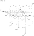
- FIG. 6 is a view of a first operating state of the lighting apparatus of FIG. 1 .
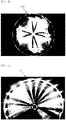
- FIG. 7 is a view of a second operating state of the lighting apparatus of FIG. 1 .
- a plurality of first light sources formed of a white light emitting diode (LED) package facing a central portion are disposed to be evenly spaced at an outer portion of the apparatus, and four second light sources formed of red LED packages facing the outer portion are disposed to have backs thereof facing one another at the central portion of the apparatus.
- LED white light emitting diode
- each red LED package is converted into linear light and displayed due to patterns of each pattern area.
- each red LED package is illustrated as a form of providing two linear lights toward two pattern areas.
- light from each of the white LED package is converted into and seen as linear light in the form in which light width decreases while moving from the outer portion toward the central portion and moves from a thickness direction of the apparatus toward a lower portion of the central portion due to patterns of each pattern area.
- light images with different colors and shapes may be implemented in a single lighting module by mixing LED packages emitting light with different colors, and thereby not only a size of a light source and a material cost be reduced but also a benefit in terms of design can be achieved without installing two or more separate lighting modules.
- LED packages having colors of white and red are used in the present embodiment described above but the embodiment is not limited thereto, and may be implemented by substituting or adding LED packages with other colors such as amber or the like.
- FIG. 8 is a cross-sectional view of a lighting apparatus according to another embodiment of the present invention
- FIG. 9 is an example view of a reflective pattern of the lighting apparatus of FIG. 8 .
- a lighting apparatus 200 includes a light guide portion 10, a three-dimensional effect formation portion 20, a first light source 50a, and a second light source 50b.
- the lighting apparatus 200 may further include a reflective pattern 140 and a protective layer 60 on a reflective layer 30.
- the light guide portion 10, the three-dimensional effect formation portion 20, the reflective layer 30, a PCB 40, the first light source 50a, the second light source 50b, a separating area 120, and an adhesive pattern 130 which are in the lighting apparatus 200 are substantially the same as the corresponding components of the lighting apparatus 100 described above with reference to FIG. 3 , thus detailed description thereof will be omitted.
- the reflective pattern 140 is provided on the reflective layer 30 to control reflection efficiency and a reflective area of the reflective layer 30.
- the reflective pattern 140 may be implemented by applying a material containing a reflective substance onto one surface of the reflective layer 30 facing a pattern layer 20a using a printing process.
- the reflective pattern 140 may be provided in a form in which a pattern unit 141 having a hexagonally shaped cross-section is arranged in a honeycomb pattern as illustrated in FIG. 9 .
- the reflective pattern 140 may use the same material as the material of the reflective layer 30.
- TiO 2 , CaCO 3 , BaSO 4 , Al 2 O 3 , silicon, poly styrene (PS), or the like may be used as the material of the reflective pattern 140.
- the protective layer 60 is disposed on the light guide portion 10 to protect the light guide portion 10.
- the protective layer 60 is properly used for protecting the flexible light guide portion 10 when the light guide portion 10 is a resin layer.
- the protective layer 60 is formed of a film material having transparency and durability, and, for example, polyethylene terephthalate (PET) or the like may be used as the film material.
- a flexible lighting apparatus may be implemented, and more various light images may be implemented when implementing the linear light having a three-dimensional effect in the flexible lighting apparatus using patterns 22 and different light sources by controlling areas and performance of light diffusion and light scattering using the separating area 120, the adhesive pattern 130, the reflective pattern 140, or a combination thereof.
- the adhesive pattern 130 may contain a reflective substance, be formed as a predetermined pattern (a honeycomb shape or the like), and may be used to limit reflectivity and a reflective area of the reflective layer 30.
- the adhesive pattern 130 may not be formed and only the reflective pattern 140 may be formed on the reflective layer 30 depending on an implementation.
- FIG. 10 is a schematic cross-sectional view of the lighting apparatus according to still another embodiment of the present invention.
- a lighting apparatus 300 includes a light guide portion 10, a three-dimensional effect formation portion 20, a first light source 50a, and a second light source 50b.
- the lighting apparatus 300 may further include a separating film 70 between a pattern layer 20a and the light guide portion 10.
- the lighting apparatus 300 may include a control unit 310 and a power supply unit 320 which are connected to the first light source 50a and the second light source 50b via a PCB 40, and may include a support portion 330 which supports the light guide portion 10, the three-dimensional effect formation portion 20, and the PCB 40.
- the present embodiment has a major feature of a pattern 22 disposed at one surface of the pattern layer 20a and facing the light guide portion 10 rather than facing the PCB 40.
- the light guide portion 10, the three-dimensional effect formation portion 20, the PCB 40, the first light source 50a, and the second light source 50b, which are in the lighting apparatus 300, are substantially the same as the corresponding components of the lighting apparatus described above with reference to FIG. 3 or FIG. 8 , thus detailed description thereof will be omitted.
- the separating film 70 separates the pattern 22 provided at one surface of the pattern layer 20a and the light guide portion 10 which covers the pattern 22 to clearly define a boundary therebetween. That is, when the pattern layer 20a is disposed on a reflective layer 30 and the light guide portion 10 is disposed on the pattern layer 20a, the separating film 70 prevents a boundary of the pattern 22 for light refraction and light reflection from becoming unclear because the pattern 22 of the pattern layer 20a is buried by the light guide portion 10. Such a phenomenon occurs when a refractive index difference between the pattern layer 20a and the light guide portion 10 is small.
- an inclined surface of the pattern 22 may not adequately perform functions of reflection and refraction due to the resin layer which forms the light guide portion 10.
- a refractive index of the light guide portion 10 and a refractive index of the pattern layer 20a are similar to each other, for example, when the refractive index difference is 0.2 or less, the inclined surface of the pattern 22 positioned therebetween may not adequately perform the action of refraction and reflection for incident light.
- the separating film 70 is disposed between the pattern 22 and the light guide portion 10 to make the boundary between the light guide portion 10 and the pattern 22 clear, and thereby enables the functions of reflection and refraction of the incident light at the pattern 22 to be smoothly performed.
- the pattern 22 of the three-dimensional effect formation portion 20 has a form which is disposed amid the light guide portion 10. That is, when the pattern layer 20a is provided with the same material as the light guide portion 10 or provided with a light guide material (a particular resin) in which the refractive index difference therebetween is 0.2 or less, the pattern 22 is substantially buried in the light guide resin layer provided by the pattern layer 20a and the light guide portion 10 but may maintain its function by the separating film 70 on the pattern.
- the separating film 70 may be a metallic coating layer disposed between the light guide portion 10 and the pattern layer 20a to maintain the refractive index difference therebetween as a certain value or more.
- the separating film may be provided with the same or similar material as the material of the reflective layer (see reference numeral 30 of FIG. 3 ).
- the control unit 310 is connected to the first light source 50a and the second light source 50a via the PCB 40 and controls operation of the first light source 50a and the second light source 50a.
- the control unit 310 selectively controls operation of the first light source 50a and the second light source 50a to function so that light with a color preset by an LED package of each power supply radiates via the lighting apparatus.
- the control unit 310 may be mounted on the PCB 40 with a driving circuit or driving device mounted on the PCB 40 to control the first light source 50a and the second light source 50a, but is not limited thereto, and may be implemented as at least a functional part of a control unit of an application using the lighting apparatus 300 or a composition part which performs the corresponding function thereto.
- the control unit of the application may be one among a plurality of vehicle control units installed in a vehicle.
- the power supply unit 320 is connected to the first light source 50a and the second light source 50a via the PCB 40 or the control unit 310, and supplies electric power to the first light source 50a and the second light source 50a. According to a control from the control unit 310, the power supply unit 320 may be operated to supply power to any one of the first light source 50a and the second light source 50a and stop supplying power to the other.
- the power supply unit 320 is mounted in the lighting apparatus 300 and may be implemented with battery power connected to the PCB 40 or control unit 310, but is not limited thereto.
- the power supply unit 320 may be a wiring or connector which connects the PCB 40 or the control unit 310 to commercial electricity.
- the power supply unit 320 may include a power converter (not shown) which converts the commercial electricity to driving power.
- the support portion 330 may be a frame, a case, or a housing which supports components of the lighting apparatus 300. Depending on a lighting application which uses the lighting apparatus 300, the support portion 330 may be provided with various structures, forms, or materials. For example, the support portion 330 may be implemented as a part of lighting installation targets such as a building, a facility, furniture, etc. In addition, when the lighting apparatus 300 is used as a vehicle lamp, the support portion 330 may be an outer lens of the vehicle lamp.
- FIGS. 11 to 13 are views for describing a pattern structure applicable to the three-dimensional effect formation portion of the lighting apparatus of FIG. 1 .
- the pattern 22 of the three-dimensional effect formation portion 20 has a pattern structure in a triangular cross-section shape.
- the inclined surface 221 formed on the triangular cross-section structure has a predetermined inclination angle with respect to an x direction.
- the inclined surface 221 may be designed to be inclined by a predetermined inclination angle ⁇ with respect to a direction (a z direction) perpendicular to a first surface or the second surface 12 of the light guide portion.
- the inclination angle ⁇ of the inclined surface 221 may be about 5° or more and about 85° or less.
- the inclination angle ⁇ may be limited considering a refractive index of the light guide portion but may basically be in the range of about 5° to 85° when minimum and maximum angles in which reflection and refraction are available at the inclined surface 221 are considered.
- the inclination angle of the inclined surface 221 may be in the range of greater than about 33.7° and smaller than 50.3° depending on a reference direction (the z direction or the x direction) or may be in the range of greater than about 49.7° and smaller than 56.3°.
- the light guide portion or the three-dimensional effect formation portion 20 may be provided using a material with a high refractive index depending on an implementation.
- a material with a high refractive index depending on an implementation.
- n a refractive index
- the inclination angle of the inclined surface of the pattern 22 may be in the range of greater than about 23.6° and smaller than 56.3° depending on the refractive index of the pattern.
- Equation 1 The inclination angle according to the above-described refractive index conforms to Snell's law and may be represented as Equation 1 below.
- Equation 1 sin ⁇ 1 represents an incident angle or a refraction angle of light in a first medium having a first refractive index (n 1 ), and sin ⁇ 2 represents a refraction angle or an incident angle of light in a second refractive index (n 2 ).
- an inclined surface of the pattern which forms the three-dimensional effect formation portion may be provided with an inclination angle which may adequately reflect or refract incident light in the range of about 5° to about 85°.
- a width W between adjacent unit patterns versus a height H may be limited by a predetermined ratio.
- the width W may be a certain interval between two adjacent unit patterns, that is, a pitch.
- the width W is provided to be the same as the height H or smaller.
- the width W is provided to be greater than the height H.
- the width W of the above-described pattern 22 may be in the range of about 10 ⁇ m to about 500 ⁇ m.
- the width W may be an average interval between two unit patterns adjacent to each other in the x direction, and may be adjusted depending on a pattern design arrangement structure or a desired form of light image.
- a ratio (h/w) of the width W (or diameter) versus a height of the pattern 22 may be designed to be about 1/2 or less or an inclination angle ⁇ of the inclined surface thereof may be designed to be about 60° or less to implement linear light.
- a depth of the concave portion is lower than when the ratio (h/w) of the width to the height of the pattern 22 is 1 or more, and thereby manufacturing the pattern is easier.
- the pattern 22 of the three-dimensional effect formation portion 20 may be provided in a semi-circular cross-section shape, a semi-ellipse cross-section shape, or a lenticular shape.
- the pattern 22 is provided with the inclined surface 221 inclined at a predetermined angle in the thickness direction of the light guide portion or at the direction (the z direction) perpendicular to the second surface opposite to the first surface of the light guide portion.
- the pattern 22 may have a symmetrical shape based on a central line of the pattern in the z direction.
- the inclined surface 221 of the pattern 22 may have a structure in which a position on the inclined surface which the incident light BL0 meets changes depending on a position of the incident light BL0 because of the semi-circular cross-section structure. That is, since the inclined surface 221 of the pattern 22 in the present embodiment is a surface that touches an arbitrary point on a circular arc, a tangent touching an arbitrary point on the pattern 22 may be placed at the predetermined inclination angle ⁇ from the direction (the z direction) perpendicular to the second surface 12 of the light guide portion.
- the inclination angle ⁇ may be greater than 0° and less than 90° depending on a position on the semi-circular cross-section at which the incident light BL0 collides.
- the pattern 22 of the three-dimensional effect formation portion 20 may further include a separating portion 222 provided between two unit patterns adjacent to each other.
- the pattern 22 includes a first unit pattern Cm-1, a second unit pattern Cm, and a third unit pattern Cm+1 (here, m is a natural number of 2 or more)
- the three-dimensional effect formation portion 20 may include separating portions 222 between the first unit pattern Cm-1 and the second unit pattern Cm and between the second unit pattern Cm and the third unit pattern Cm+1.
- the separating portion 222 is a portion in which a concave unit pattern is not formed on the second surface 12 of the light guide portion, and may be a portion of the second surface 12 positioned between adjacent two unit patterns.
- the separating portion 222 is a separating interval between two unit patterns adjacent to each other, and may be provided for convenience of a manufacturing process.
- the separating portion 222 may be omitted depending on a pattern design.
- a width W1 of the separating portion 222 is designed to be less than the width W of a unit pattern.
- the width W1 of the separating portion 222 may be about 1/5 of the width W of the pattern 22 or several ⁇ m or less.
- smooth linear light may be difficult to be implemented at the pattern 22.
- the pattern 22 of the three-dimensional effect formation portion 20 is provided with a pattern structure in a polygonal cross-section shape.
- a cross-section of the inclined surface 221 of the pattern 22 has a shape of a broken line graph.
- the inclined surface 221 of the pattern 22 may have a plurality of inclination angles ⁇ 1 and ⁇ 2 depending on the number of segments of the broken line graph from the thickness direction of the light guide portion or from the direction (the z direction) perpendicular to the second surface 12 of the light guide portion.
- the second inclination angle ⁇ 2 may be larger than the first inclination angle ⁇ 1.
- the first inclination angle ⁇ 1 and the second inclination angle ⁇ 2 may be designed to be within a range of greater than 5° and smaller than 85° depending on the position at which the incident light BL0 meets.
- the three-dimensional effect formation portion 20 of the present embodiment may include the separating portion 222 provided between two unit patterns adjacent to each other.
- the width W1 of the separating portion 222 is smaller than the width W of the pattern for implementing smooth linear light on the three-dimensional effect formation portion 20.
- the width W1 of the separating portion 222 may be several ⁇ m or less or about 1/5 or less of the width W of the pattern.
- the three-dimensional effect formation portion 20 of the present embodiment may include a severed surface 223 on the pattern 22 which is nearly parallel with the first surface or the second surface.
- the severed surface 223 is a portion that substantially does not allow light to be radiated to the outside by reflection or refraction of incident light, and because linear light implemented by the pattern 22 may have a severed portion corresponding to the severed surface 223, a width W2 of the severed surface 223 may be adequately designed to be several ⁇ m or less for consecutively implementing linear light. Meanwhile, the severed surface 223 may be omitted when implementing consecutive linear light, and it is a matter of course that the severed surface 223 may be used when implementing discontinuous linear light.
- any structure including a shape such as a straight line, a curve, a broken line graph, or a combination thereof which may radiate light advancing inside the light guide portion 10 toward the first surface or the second surface by refracting or reflecting it may be applicable as a cross-section of the inclined surface of each pattern in the above-described embodiment.
- the lighting apparatus is applicable in various field of lighting that require lighting such as a vehicle lamp, a lighting apparatus for domestic use, and a lighting apparatus for industrial use.
- a vehicle lamp it is applicable to a rear combination lamp, indoor illumination, a rear light, etc.
- it may be applicable to all the fields related to lighting which have been developed and commercialized, or may be implemented according to upcoming technological advancement.
Abstract
Description
- The present invention relates to a lighting apparatus, and more particularly, to a lighting apparatus using linear light having a three-dimensional effect.
- A light emitted diode (LED) refers to a device which converts an electric signal to infrared rays or light using properties of a compound semiconductor, and is advantageous in terms of having a long life span compared to conventional other light sources and causing little environmental pollution because it does not use harmful substance unlike a fluorescent light or the like in which mercury or the like is used. In addition, an LED is advantageous in that visibility is excellent due to a high color temperature and power consumption is low when compared to other light sources.
- Thanks to the advancement and supply of LED technology, a trend of a lighting apparatus is advancing from using conventional light sources such as a fluorescent light or the like to using an LED light source. For example, as disclosed in Korean Patent Laid-Open Publication No.
10-2012-0009209 - In addition, in some conventional technologies, a lighting apparatus in which surface light-emitting performance is enhanced by adding an optical sheet such as a diffusion sheet, a prism sheet, a protective sheet, or the like to the light guide plate has been suggested.
- However, a conventional lighting apparatus using an LED light source is limited in thinning a thickness of an entire product due to a thickness of the light guide plate itself, is disadvantageous due to being difficult to apply to a housing or an application in which a curve is formed because a material of the light guide plate is not flexible, and is disadvantageous in designing a product and modifying a design due to the light guide plate. Accordingly, a solution which can be easily applied to diverse applications such as indoor and outdoor lighting, vehicle lighting, or the like, and can effectively implement light images as desired is required.
- The present invention is directed to providing a lighting apparatus capable of implementing various light images having a three-dimensional effect using different kinds of light sources in combination.
- The present invention is also directed to providing a lighting apparatus for a vehicle application capable of reducing a size of a light source and obtaining benefits from a design perspective.
- One aspect of the present invention includes a light guide portion having a first surface and a second surface opposite to the first surface, and having a predetermined thickness between the first surface and the second surface, a three-dimensional effect formation portion disposed in the light guide portion or on a surface thereof and including a pattern, a first light source disposed in a first area of the pattern and irradiating incident light of a first color toward the pattern, and a second light source disposed in a second area of the pattern and irradiating incident light of a second color different from the first color toward the pattern, wherein the pattern includes inclined surfaces sequentially arranged on a pattern arrangement surface parallel with the second surface and having an inclination angle with respect to the pattern arrangement surface, and generates linear light of a first path by guiding the incident light in a first surface direction which faces the first surface or in a second surface direction which faces the second surface by refraction and reflection at the inclined surface.
- According to the present invention, a lighting apparatus capable of implementing various light images having a three-dimensional effect using different kinds of light sources in combination can be provided.
- According to the present invention, a lighting apparatus for a vehicle application capable of reducing a size of a light source and obtaining benefits in design can be provided. In addition, a lighting apparatus in which a material is reduced and two or more functions are implemented in a single module can be provided.
-
-
FIG. 1 is a plan view of a lighting apparatus according to one embodiment of the present invention. -
FIG. 2 is a schematic front view of the lighting apparatus ofFIG. 1 . -
FIG. 3 is a partially enlarged schematic cross-sectional view of the lighting apparatus ofFIG. 1 . -
FIGS. 4 and5 are views for describing an operating principle of a three-dimensional effect formation portion of the lighting apparatus ofFIG. 1 . -
FIG. 6 is a view of a first operating state of the lighting apparatus ofFIG. 1 . -
FIG. 7 is a view of a second operating state of the lighting apparatus ofFIG. 1 . -
FIG. 8 is a cross-sectional view of a lighting apparatus according to another embodiment of the present invention. -
FIG. 9 is an example view of a reflective pattern of the lighting apparatus ofFIG. 8 . -
FIG. 10 is a schematic cross-sectional view of a lighting apparatus according to still another embodiment of the present invention. -
FIGS. 11 to 13 are views for describing a pattern structure applicable to the three-dimensional effect formation portion of the lighting apparatus ofFIG. 1 . - Exemplary embodiments according to the present invention will now be described more fully hereinafter with reference to the accompanying drawings so that those having ordinary skill in the art can easily embody them. However, since embodiments of the invention described in this specification and constitutions illustrated in the drawings are merely preferred embodiments, it should be understood that there may be various equivalents or modifications that may substitute these embodiments at the time of present application. In addition, in the detailed description of operating principles of the preferred embodiments of the present invention, detailed descriptions of well-known functions or configurations will be omitted where they may unnecessarily obscure the subject matters of the invention. In addition, since terms described below are defined considering functions of the present invention, definitions of these terms may be made on the basis of the content throughout the specification. Throughout the drawings, elements performing similar functions and actions are designated by the same reference numerals.
-
FIG. 1 is a plan view of a lighting apparatus according to one embodiment of the present invention. - Referring to
FIG. 1 , alighting apparatus 100 according to one embodiment of the present invention includes alight guide portion 10, a three-dimensionaleffect formation portion 20, afirst light source 50a, and asecond light source 50b. - The
light guide portion 10 is provided in the form of a plate or film which includes a first surface (seereference numeral 11 ofFIG. 3 ) and a second surface (seereference numeral 12 ofFIG. 12 ) which is a surface opposite to the first surface and roughly parallel therewith. In the present embodiment, the second surface may correspond to a pattern arrangement surface in which apattern 22 of the three-dimensionaleffect formation portion 20 is provided. - The
light guide portion 10 includes a transparent material, for example, a glass, a resin, etc. Light transmittance of the transparent material may be about 50 % or more, and may preferably be about 80 % or more. When a resin is used, thelight guide portion 10 may be provided as an ultraviolet (UV) curing resin which includes an oligomer. The oligomer includes any one material selected from a urethane acrylate, an epoxy acrylate, a polyester acrylate, and an acrylic acrylate. - The three-dimensional
effect formation portion 20 includes thepattern 22 as shown in the enlarged view of a particular area B1. Thepattern 22 may have a striped shape which includes a convex portion, in which a length direction thereof in a shape of a knoll or a wall extends in a first direction, and a concave portion, in which a length direction thereof in a shape of a trench or a valley extends in the first direction, wherein the convex portion and concave portion are sequentially arranged in a second direction which crosses the first direction. In the present embodiment, thepattern 22 is provided with convex and concave shapes of straight line stripes in which a plurality of pattern units roughly extend in parallel, but is not limited thereto and may be provided with convex and concave shapes of curved stripes. - In addition, in the present embodiment, the
pattern 22 includes patterns P1, P2, P3, P4, and P5 provided having different pattern arrangement directions in different pattern areas A1, A2, etc. When pattern units at each pattern area integrally extend, abent pattern portion 21 may be formed between pattern units of pattern areas adjacent to each other. - The
pattern 22 includes an inclined surface (seereference numeral 221 ofFIG.3 ) inclined with respect to the second surface or the pattern arrangement surface parallel with the second surface. Thepattern 22 guides the light which reflects and moves inside thelight guide portion 10 to a direction facing the first surface (see z direction inFIG. 3 ) or a direction facing the second surface (see -z direction inFIG. 3 ) by refraction and reflection in the inclined surface. In addition, thepattern 22 generates a first linear light which moves in a pattern arrangement direction perpendicular to a pattern extension direction from a first incident light which moves via thefirst surface 11 of thelight guide portion 10 and between the pattern arrangement surfaces. The first linear light has a predetermined width of light in the optical path depending on a pattern designed and has a perceivable depth in a thickness direction of thelight guide portion 10. - In the present embodiment, with respect to the
light guide portion 10 having a circular shape on a plane, thepattern 22 includes a polygonal outermost pattern unit which is inscribed in the second surface of thelight guide portion 10 or in an inside circular plan corresponding to the second surface, and a plurality of pattern units in a concentrically circular shape arranged to be evenly spaced from the outermost pattern unit toward the center. Accordingly, thepattern 22 implements a plurality of first linear lights which are radially irradiated from the center of thelight guide portion 10 toward edges, or a plurality of first linear lights which are radially irradiated from the edges of thelight guide portion 10 toward the center. - In the present embodiment, a width, length and optical path of the first linear light may be the same or different depending on design of the patterns P1, P2, P3, P4, and P5 at each pattern area. In addition, the
pattern 22 is provided by a separate pattern layer (seereference numeral 20a ofFIG. 3 ) disposed on the second surface of thelight guide portion 10 but is not limited thereto, and may be implemented by directly processing the second surface of thelight guide portion 10 to make a pattern in convex and concave shapes - The
first light source 50a is disposed to be positioned at the edges of thelight guide portion 10. Thefirst light source 50a may be supported by a separate support portion or a printed circuit board (PCB), and may be coupled to a stacked structure of thelight guide portion 10 and the three-dimensionaleffect formation portion 20 and buried by thelight guide portion 10 depending on an implementation. - The
second light source 50b is disposed to be positioned at a central portion of thelight guide portion 10. Similarly to thefirst light source 50a, thesecond light source 50b may be supported by a support portion or a PCB (seereference numeral 40 ofFIG. 3 ) or buried by thelight guide portion 10. The PCB may be coupled to one surface of the stacked structure to face thelight guide portion 10 interposing the three-dimensionaleffect formation portion 20. -
FIG. 2 is a schematic front view of the lighting apparatus ofFIG. 1 . - Referring to
FIG. 2 , thelighting apparatus 100 according to the present embodiment may be bent to have a predetermined curvature or have a flexibility to be bent as needed by limiting a thickness of the light guide portion and providing the PCB connected to the first light source and the second light source as a flexible PCB. - For example, the
lighting apparatus 100 may have a curvature in a shape in which a central portion of the disk shape structure is spaced a certain amount of distance from a surface F1 and an edge of the disk shape structure is in contact with the surface F1. Of course, thelighting apparatus 100 is not limited to the structure having a fixed curvature, but may be provided with flexibility to be attached, having a corresponding curvature, to one surface such as a support portion, a housing, or an outer lens for a vehicle lamp, which has a predetermined curvature. -
FIG. 3 is a partially enlarged schematic cross-sectional view of the lighting apparatus ofFIG. 1 .FIG. 3 corresponds to a cross-section of the lighting apparatus ofFIG. 1 taken along line III-III. - Referring to
FIG. 3 , thelighting apparatus 100 according to the present embodiment includes thelight guide portion 10, the three-dimensionaleffect formation portion 20, the firstlight source 50a, and the secondlight source 50b. In addition, thelighting apparatus 100 may further include areflective layer 30. - The three-dimensional
effect formation portion 20 is provided by disposing thepattern layer 20a having thepattern 22 at one surface in the second surface of thelight guide portion 10. A thermoplastic polymer, a photopolymer, or the like may be used as a material of thepattern layer 20a. Thepattern 22 is provided at one surface of thepattern layer 20a, but is not limited thereto. - In the present embodiment, the
pattern 22 is disposed to face thereflective layer 40. In the case, when thepattern layer 20a is coated with a resin to form thelight guide portion 10, thepattern 22 covered by the resin is prevented from losing its function. That is, thepattern 22 guides incident light moving into thelight guide portion 10 to be linear light having a certain amount of light width at a particular optical path by refraction and reflection at an inclined surface of the pattern, and while the refraction and reflection actions may not be feasible at an inclined surface of thepattern 22 when covered with a resin having a similar refractive index, the above-described problem is prevented in the present embodiment by disposing thepattern 22 in thepattern layer 20a to face thereflective layer 30 disposed at the opposite side of thelight guide portion 10. - The
pattern layer 20a may be fixed on thereflective layer 30 by anadhesive pattern 130. Theadhesive pattern 130 is disposed on a periphery of the firstlight source 50a and the secondlight source 50b to stabilize a disposition and secure reliability of thepattern layer 20a. By the disposition of theadhesive pattern 130, thepattern layer 20a on the periphery of light sources may be prevented from being easily separated in comparison to other areas due to the firstlight source 50a and the secondlight source 50b disposed to pass through thepattern layer 20a. - The
reflective layer 30 is disposed between thePCB 40 and thepattern layer 20a. When disposing thepattern layer 20a on thereflective layer 30, thepattern 22 is disposed to face thereflective layer 30 rather than thelight guide portion 10. - The
reflective layer 30 may be provided on one surface of thePCB 40 in the form of a film. Thereflective layer 30 is provided with a material with high reflection efficiency, and reflects light coming in the first surface direction of thelight guide portion 10 from thelight sources pattern 22 of the three-dimensionaleffect formation portion 20 back toward a side of thepattern 22. By the action of thereflective layer 30, thelighting apparatus 100 may reduce optical loss and more clearly display linear light having a three-dimensional effect. - A synthetic resin containing a dispersed white pigment may be used as a material of the
reflective layer 30 to enhance properties of light reflection and boosting light dispersion. For example, a titanium oxide, an aluminum oxide, a zinc oxide, a carbonate, barium sulfate, calcium carbonate, etc. may be used as the white pigment, and polyethylene terephthalate, polyethylene naphthalate, acrylic, polycarbonate, polystyrene, polyolefin, cellulose acetate, weather resistant vinyl chloride, etc. may be used as a material of a synthetic resin, but is not limited thereto. In still another embodiment, thereflective layer 30 may be implemented as silver (Ag), aluminum (Al), stainless steel (304SS), or the like. - The
lighting apparatus 100 according to the present embodiment may include aseparating area 120 between thepattern layer 20a and thereflective layer 30. The separatingarea 120 may be an air layer or a vacuum layer and may be surrounded by theadhesive pattern 130. - When the
reflective layer 30, the separatingarea 120, and theadhesive pattern 130 are utilized, more various light images may be implemented by controlling linear light with different colors implemented in a single module depending on a design pattern or by controlling performance of light diffusion or light concentration for a dark portion around the linear light. -
FIG. 4 is a schematic plan view for describing an operating principle of the three-dimensional effect formation portion of the lighting apparatus ofFIG. 1 . - Referring to
FIG. 4 , in the lighting apparatus according to the present embodiment, when a first pattern P1 is designed at a first pattern area A1 of thepattern layer 20a to extend in an x direction and sequentially arranged in a first direction (a -y direction) perpendicular to the x direction and a second pattern P2 is designed at a second pattern area A2 of thepattern layer 20a to extend in a D2 direction and sequentially arranged in a second direction perpendicular to the D2 direction, a first incident light of a second light source disposed to face the first pattern area A1 is converted into first linear light BL1 which moves along a first path perpendicular to the extension direction (the x direction) of each pattern of pattern units in the first pattern P1. In addition, first incident light of another second light source disposed to face the second pattern area A2 is converted into another first linear light BL1 which moves through an optical path perpendicular to the extension direction (the D2 direction) of each pattern of pattern units in the second pattern P2. - In the present embodiment, in the
pattern 22 of the three-dimensionaleffect formation portion 20, the pattern extension direction (the x direction or the D2 direction) may be a direction in which a particular straight line on an inclined surface of the pattern units at each pattern area extends or a direction in which a particular tangent of a particular curve on each inclined surface extends. Here, the particular straight line or curve may be parallel with the first surface and the second surface of thelight guide portion 10. - In the case of designing pattern, when all of the pattern extension directions of the pattern units are designed to be parallel to each other, the first linear light BL1 formed by patterns has a form of straight line advancing in a direction perpendicular to the pattern extension direction of each pattern unit. This is because the movement of light is concentrated along a least moving path of the pattern according to Fermat's principle stated as 'light that moves between two points in a medium moves along the path that can be traversed in the least time.'
- In the present embodiment, some incident light on the
pattern 22 of the three-dimensionaleffect formation portion 20 fails to be converted into the first linear light BL1. That is, thepattern 22 disperses some incident light BL0 (hereinafter referred to as peripheral light) in a direction besides the first path (the optical path of the linear light). - The peripheral light BL0 refers to incident light refracted, reflected, and dispersed to other paths rather than the first path on the
pattern 22. Since the peripheral light BL0 is dispersed into a relatively wider range in thelight guide portion 10 in comparison to the linear light and is not light heading towards a reference point, the peripheral light BL0 forms a peripheral portion or a dark portion in which luminance is relatively low in comparison to a portion of the first linear light BL1 (hereinafter referred to as bright portion) around the bright portion. The reference point may be a point at which an observer, a camera, or the like is positioned. - In addition, when a pattern of the three-dimensional
effect formation portion 20 is designed, an interval Lp between two pattern units adjacent to each other may be in the range of about 10 to 500 µm. The interval Lp may correspond to a pitch or an average interval of patterns. In addition, minimum and maximum intervals for implementing linear light having a three-dimensional effect are considered for the interval Lp, thus implementing the linear light may be limited when the intervals deviate from the minimum and maximum range. That is, when the intervals deviate from the range, it is difficult to implement indirect light sources whose distance sequentially recedes from the reference point due to the inclined surfaces sequentially arranged on thepattern 22, thereby linear light having a three-dimensional effect may not be implemented. - According to the
lighting apparatus 100 of the present embodiment, linear light generated by refraction and reflection at the inclined surface of thepattern 22 may be implemented to be controlled to a predetermined light width and a predetermined length by designing the pattern. For example, by designing a pattern having a predetermined width, a particular light width and optical path of the linear light may be implemented to have a uniform light width and extend to an extent as much as a first length, to have a light width gradually decreasing and extend to an extent as much as a second length shorter than the first length, or to have a light width gradually increasing and extend to an extent which is similar to the first length, or shorter or longer than the first length. - Meanwhile, the above-described embodiment is described based on a pattern structure expanding in a striped form with straight lines at least at each pattern area, but it is not limited thereto, and pattern extension directions of the pattern unit of the
pattern 22 may be designed to cross at least at a point but not be parallel to each other depending on implementation. In the case, an optical path of the linear light passing the pattern is bent toward a side at which a distance (or an interval) between two pattern units adjacent to each other is small and may become a curved form according to Fermat's principle. -
FIG. 5 is a partially enlarged schematic cross-sectional view for describing an operating principle of the three-dimensional effect formation portion of the lighting apparatus ofFIG. 1 . - Referring to
FIG. 5 , in thelighting apparatus 100 according to the present embodiment, when light is incident from a particular light source LS on thelight guide portion 10, an incident light BL0 which passes through thelight guide portion 10 moves by being reflected in thelight guide portion 10 at below a critical angle determined by a refractive index of thelight guide portion 10 and a refractive index of an external medium (air). - When the incident light BL0 meets the
inclined surface 221 of thepattern 22, the incident light BL0 is refracted and reflected by theinclined surface 221 to advance in the first surface direction (the z direction) facing thefirst surface 11 of thelight guide portion 10 or in the second surface direction (the -z direction) facing the second surface, and is radiated to outside thelight guide portion 10. - In the case described above, each pattern unit of the
pattern 22 works as an indirect light source which refracts or reflects the incident light by the inclined surface and radiates the incident light in the first surface direction or in the second surface direction. Here, the indirect light sources formed by each of the pattern units of thepattern 22 appear to be positioned to gradually recede depending on distances from the light source LS when viewed from a certain reference point outside the lighting apparatus. - For example, when the pattern units are sequentially arranged in the pattern arrangement direction (the -x direction) based on the light source LS and include a first pattern unit P11 at a first area a1, a second pattern unit P12 at a second area a2, and a third pattern unit P13 at a third area a3 from the nearest to the light source along the optical path in the pattern arrangement direction, a second optical path which is a travel distance of incident light reaching the second pattern unit P12 from the light source LS is longer than a first optical path from the light source LS to the first pattern unit P11 and shorter than a third optical path from the light source LS to the third pattern unit P13. That is, a second distance L2 which is an optical path of the light by the second pattern unit P12 from a second indirect light source LS2 toward the reference point is longer than a first distance L1 which is an optical path of the light by the first pattern unit P11 from a first indirect light source LS1 toward the reference point and shorter than a third distance L3 which is an optical path of the light by the third pattern unit P13 from a third indirect light source LS3 toward the reference point.
- As described above, when viewed from a certain reference point, each pattern unit of the
pattern 22 works as an indirect light source which is sequentially arranged on a particular optical path, positioned to gradually recede, and gradually decreases in luminance, and thereby linear light having a three-dimensional effect on an optical path is implemented by a structure of thepattern 22. - The linear light having a three-dimensional effect described above refers to a light image having a perceivable depth in which linear light guided and restricted to a particular light width in an optical path preset by a pattern gradually moves into the
light guide portion 10 from the first surface of thelight guide portion 10 toward the second surface (or the pattern arrangement surface) thereof (or the other way around) when viewed from the first surface direction or the second surface direction. - Meanwhile, in the pattern units of the first pattern unit to the third pattern units P11, P12, and P13 described above, the second pattern unit P12 may be a pattern unit positioned immediately after the first pattern unit P11 on the second surface of the
light guide portion 10 or the pattern unit interposed between the first pattern unit P11 and a predetermined number of other pattern units when viewed from the light source LS. Similarly, the third pattern unit P13 may be a pattern unit positioned immediately after the second pattern unit P12 or the pattern unit interposed between the second pattern unit P12 and a predetermined number of other pattern units when viewed from the light source. -
FIG. 6 is a view of a first operating state of the lighting apparatus ofFIG. 1 .FIG. 7 is a view of a second operating state of the lighting apparatus ofFIG. 1 . - In the circular shaped lighting apparatus of the present embodiment, a plurality of first light sources formed of a white light emitting diode (LED) package facing a central portion are disposed to be evenly spaced at an outer portion of the apparatus, and four second light sources formed of red LED packages facing the outer portion are disposed to have backs thereof facing one another at the central portion of the apparatus.
- Referring to
FIG. 6 , light from each of the red LED packages is converted into linear light and displayed due to patterns of each pattern area. In the present embodiment, since two pattern areas are disposed facing each other at a light emitting surface of one red LED package, each red LED package is illustrated as a form of providing two linear lights toward two pattern areas. - Referring to
FIG. 7 , light from each of the white LED package is converted into and seen as linear light in the form in which light width decreases while moving from the outer portion toward the central portion and moves from a thickness direction of the apparatus toward a lower portion of the central portion due to patterns of each pattern area. - According to the present embodiment described above, light images with different colors and shapes may be implemented in a single lighting module by mixing LED packages emitting light with different colors, and thereby not only a size of a light source and a material cost be reduced but also a benefit in terms of design can be achieved without installing two or more separate lighting modules.
- Meanwhile, two kinds of LED packages having colors of white and red are used in the present embodiment described above but the embodiment is not limited thereto, and may be implemented by substituting or adding LED packages with other colors such as amber or the like.
-
FIG. 8 is a cross-sectional view of a lighting apparatus according to another embodiment of the present invention, andFIG. 9 is an example view of a reflective pattern of the lighting apparatus ofFIG. 8 . - Referring to
FIG. 8 , alighting apparatus 200 according to the present embodiment includes alight guide portion 10, a three-dimensionaleffect formation portion 20, a firstlight source 50a, and a secondlight source 50b. In addition, thelighting apparatus 200 may further include areflective pattern 140 and aprotective layer 60 on areflective layer 30. - The
light guide portion 10, the three-dimensionaleffect formation portion 20, thereflective layer 30, aPCB 40, the firstlight source 50a, the secondlight source 50b, a separatingarea 120, and anadhesive pattern 130 which are in thelighting apparatus 200 are substantially the same as the corresponding components of thelighting apparatus 100 described above with reference toFIG. 3 , thus detailed description thereof will be omitted. - The
reflective pattern 140 is provided on thereflective layer 30 to control reflection efficiency and a reflective area of thereflective layer 30. Thereflective pattern 140 may be implemented by applying a material containing a reflective substance onto one surface of thereflective layer 30 facing apattern layer 20a using a printing process. - The
reflective pattern 140 may be provided in a form in which apattern unit 141 having a hexagonally shaped cross-section is arranged in a honeycomb pattern as illustrated inFIG. 9 . Thereflective pattern 140 may use the same material as the material of thereflective layer 30. For example, TiO2, CaCO3, BaSO4, Al2O3, silicon, poly styrene (PS), or the like may be used as the material of thereflective pattern 140. - The
protective layer 60 is disposed on thelight guide portion 10 to protect thelight guide portion 10. Theprotective layer 60 is properly used for protecting the flexiblelight guide portion 10 when thelight guide portion 10 is a resin layer. Theprotective layer 60 is formed of a film material having transparency and durability, and, for example, polyethylene terephthalate (PET) or the like may be used as the film material. - According to the present embodiment, a flexible lighting apparatus may be implemented, and more various light images may be implemented when implementing the linear light having a three-dimensional effect in the flexible lighting
apparatus using patterns 22 and different light sources by controlling areas and performance of light diffusion and light scattering using theseparating area 120, theadhesive pattern 130, thereflective pattern 140, or a combination thereof. - Meanwhile, the above embodiment is described based on the
reflective pattern 140 being implemented as a pattern separate from theadhesive pattern 130, but it is not limited thereto, and thereflective pattern 140 and theadhesive pattern 130 may also be integrally formed. For example, theadhesive pattern 130 may contain a reflective substance, be formed as a predetermined pattern (a honeycomb shape or the like), and may be used to limit reflectivity and a reflective area of thereflective layer 30. In addition, , when theadhesive pattern 130 is not formed and thepattern layer 20a is supported and fixed on thereflective layer 30 by being attached or bonded to a resin layer, theadhesive pattern 130 may not be formed and only thereflective pattern 140 may be formed on thereflective layer 30 depending on an implementation. -
FIG. 10 is a schematic cross-sectional view of the lighting apparatus according to still another embodiment of the present invention. - Referring to
FIG. 10 , alighting apparatus 300 according to the present embodiment includes alight guide portion 10, a three-dimensionaleffect formation portion 20, a firstlight source 50a, and a secondlight source 50b. Thelighting apparatus 300 may further include a separatingfilm 70 between apattern layer 20a and thelight guide portion 10. In addition, thelighting apparatus 300 may include acontrol unit 310 and apower supply unit 320 which are connected to the firstlight source 50a and the secondlight source 50b via aPCB 40, and may include asupport portion 330 which supports thelight guide portion 10, the three-dimensionaleffect formation portion 20, and thePCB 40. - Although the three-dimensional
effect formation portion 20 of thelighting apparatus 300 is provided by thepattern layer 20a between thePCB 40 and thelight guide portion 10, the present embodiment has a major feature of apattern 22 disposed at one surface of thepattern layer 20a and facing thelight guide portion 10 rather than facing thePCB 40. - The
light guide portion 10, the three-dimensionaleffect formation portion 20, thePCB 40, the firstlight source 50a, and the secondlight source 50b, which are in thelighting apparatus 300, are substantially the same as the corresponding components of the lighting apparatus described above with reference toFIG. 3 orFIG. 8 , thus detailed description thereof will be omitted. - The separating
film 70 separates thepattern 22 provided at one surface of thepattern layer 20a and thelight guide portion 10 which covers thepattern 22 to clearly define a boundary therebetween. That is, when thepattern layer 20a is disposed on areflective layer 30 and thelight guide portion 10 is disposed on thepattern layer 20a, the separatingfilm 70 prevents a boundary of thepattern 22 for light refraction and light reflection from becoming unclear because thepattern 22 of thepattern layer 20a is buried by thelight guide portion 10. Such a phenomenon occurs when a refractive index difference between thepattern layer 20a and thelight guide portion 10 is small. - That is, when the
pattern 22 of the three-dimensionaleffect formation portion 20 is buried by the resin layer, an inclined surface of thepattern 22 may not adequately perform functions of reflection and refraction due to the resin layer which forms thelight guide portion 10. Particularly, when a refractive index of thelight guide portion 10 and a refractive index of thepattern layer 20a are similar to each other, for example, when the refractive index difference is 0.2 or less, the inclined surface of thepattern 22 positioned therebetween may not adequately perform the action of refraction and reflection for incident light. - In the case of the above description, linear light having a three-dimensional effect may be difficult to be implemented because incident light of the
light sources light guide portion 10 by refraction and reflection at thepattern 22 of the three-dimensionaleffect formation portion 20. Therefore, in thelighting apparatus 300 according to the present embodiment, the separatingfilm 70 is disposed between thepattern 22 and thelight guide portion 10 to make the boundary between thelight guide portion 10 and thepattern 22 clear, and thereby enables the functions of reflection and refraction of the incident light at thepattern 22 to be smoothly performed. - According to above description, the
pattern 22 of the three-dimensionaleffect formation portion 20 has a form which is disposed amid thelight guide portion 10. That is, when thepattern layer 20a is provided with the same material as thelight guide portion 10 or provided with a light guide material (a particular resin) in which the refractive index difference therebetween is 0.2 or less, thepattern 22 is substantially buried in the light guide resin layer provided by thepattern layer 20a and thelight guide portion 10 but may maintain its function by the separatingfilm 70 on the pattern. - The separating
film 70 may be a metallic coating layer disposed between thelight guide portion 10 and thepattern layer 20a to maintain the refractive index difference therebetween as a certain value or more. For example, the separating film may be provided with the same or similar material as the material of the reflective layer (seereference numeral 30 ofFIG. 3 ). - The
control unit 310 is connected to the firstlight source 50a and the secondlight source 50a via thePCB 40 and controls operation of the firstlight source 50a and the secondlight source 50a. Thecontrol unit 310 selectively controls operation of the firstlight source 50a and the secondlight source 50a to function so that light with a color preset by an LED package of each power supply radiates via the lighting apparatus. - The
control unit 310 may be mounted on thePCB 40 with a driving circuit or driving device mounted on thePCB 40 to control the firstlight source 50a and the secondlight source 50a, but is not limited thereto, and may be implemented as at least a functional part of a control unit of an application using thelighting apparatus 300 or a composition part which performs the corresponding function thereto. When the lighting apparatus is used as a vehicle lamp (a rear combination lamp, a rear light, etc.), the control unit of the application may be one among a plurality of vehicle control units installed in a vehicle. - The
power supply unit 320 is connected to the firstlight source 50a and the secondlight source 50a via thePCB 40 or thecontrol unit 310, and supplies electric power to the firstlight source 50a and the secondlight source 50a. According to a control from thecontrol unit 310, thepower supply unit 320 may be operated to supply power to any one of the firstlight source 50a and the secondlight source 50a and stop supplying power to the other. - The
power supply unit 320 is mounted in thelighting apparatus 300 and may be implemented with battery power connected to thePCB 40 orcontrol unit 310, but is not limited thereto. For example, thepower supply unit 320 may be a wiring or connector which connects thePCB 40 or thecontrol unit 310 to commercial electricity. In the case, thepower supply unit 320 may include a power converter (not shown) which converts the commercial electricity to driving power. - The
support portion 330 may be a frame, a case, or a housing which supports components of thelighting apparatus 300. Depending on a lighting application which uses thelighting apparatus 300, thesupport portion 330 may be provided with various structures, forms, or materials. For example, thesupport portion 330 may be implemented as a part of lighting installation targets such as a building, a facility, furniture, etc. In addition, when thelighting apparatus 300 is used as a vehicle lamp, thesupport portion 330 may be an outer lens of the vehicle lamp. -
FIGS. 11 to 13 are views for describing a pattern structure applicable to the three-dimensional effect formation portion of the lighting apparatus ofFIG. 1 . - Referring to
FIG. 11 , thepattern 22 of the three-dimensionaleffect formation portion 20 has a pattern structure in a triangular cross-section shape. When thepattern 22 has a triangular cross-section structure, theinclined surface 221 formed on the triangular cross-section structure has a predetermined inclination angle with respect to an x direction. In other words, theinclined surface 221 may be designed to be inclined by a predetermined inclination angle θ with respect to a direction (a z direction) perpendicular to a first surface or thesecond surface 12 of the light guide portion. - The inclination angle θ of the
inclined surface 221 may be about 5° or more and about 85° or less. The inclination angle θ may be limited considering a refractive index of the light guide portion but may basically be in the range of about 5° to 85° when minimum and maximum angles in which reflection and refraction are available at theinclined surface 221 are considered. - For example, when a refractive index of the light guide portion falls within the range of about 1.30 to about 1.80, the inclination angle of the
inclined surface 221 may be in the range of greater than about 33.7° and smaller than 50.3° depending on a reference direction (the z direction or the x direction) or may be in the range of greater than about 49.7° and smaller than 56.3°. - In addition, the light guide portion or the three-dimensional
effect formation portion 20 may be provided using a material with a high refractive index depending on an implementation. For example, in the case of manufacturing a high-luminous-intensity LED, when light with an particular incident angle passes a die and penetrates a capsule material, a total internal reflection occurs due to a difference of n (a refractive index) value between the die (n=2.50-3.50) and an ordinary polymer capsule material (n=1.40∼1.60) resulting in degradation of a light extraction efficiency, and thus a polymer with a high refractive index is used to adequately resolve the problem. That is, in the present embodiment, when thepattern 22 is provided using a polymer with a high refractive index used in manufacturing a high-luminous-intensity LED, the inclination angle of the inclined surface of thepattern 22 may be in the range of greater than about 23.6° and smaller than 56.3° depending on the refractive index of the pattern. - The inclination angle according to the above-described refractive index conforms to Snell's law and may be represented as
Equation 1 below.
- In
Equation 1, sinθ1 represents an incident angle or a refraction angle of light in a first medium having a first refractive index (n1), and sinθ2 represents a refraction angle or an incident angle of light in a second refractive index (n2). - As described above, in the lighting apparatus of the present embodiment, an inclined surface of the pattern which forms the three-dimensional effect formation portion may be provided with an inclination angle which may adequately reflect or refract incident light in the range of about 5° to about 85°.
- In addition, in the present embodiment, for convenience and the like of a manufacturing process of the
pattern 22, a width W between adjacent unit patterns versus a height H may be limited by a predetermined ratio. The width W may be a certain interval between two adjacent unit patterns, that is, a pitch. For example, when a pattern of a lighting apparatus is designed to emphasize a perceivable depth of linear light, the width W is provided to be the same as the height H or smaller. In addition, when a pattern is designed to express a relatively long image of linear light, the width W is provided to be greater than the height H. - The width W of the above-described
pattern 22 may be in the range of about 10 µm to about 500 µm. The width W may be an average interval between two unit patterns adjacent to each other in the x direction, and may be adjusted depending on a pattern design arrangement structure or a desired form of light image. - Meanwhile, when the
pattern 22 has a lenticular shape, , a ratio (h/w) of the width W (or diameter) versus a height of thepattern 22 may be designed to be about 1/2 or less or an inclination angle θ of the inclined surface thereof may be designed to be about 60° or less to implement linear light. - In addition, when the ratio (h/w) of the width to the height of the
pattern 22 is designed to be less than 1, a depth of the concave portion is lower than when the ratio (h/w) of the width to the height of thepattern 22 is 1 or more, and thereby manufacturing the pattern is easier. - According to the present embodiment, by designing an optical member using the width W and the height H of the
pattern 22 as factors for controlling properties, various light images desired to be implement by linear light having a three-dimensional effect may be efficiently and easily controlled. - Referring to
FIG. 12 , in the lighting apparatus of the present embodiment, thepattern 22 of the three-dimensionaleffect formation portion 20 may be provided in a semi-circular cross-section shape, a semi-ellipse cross-section shape, or a lenticular shape. Thepattern 22 is provided with theinclined surface 221 inclined at a predetermined angle in the thickness direction of the light guide portion or at the direction (the z direction) perpendicular to the second surface opposite to the first surface of the light guide portion. Thepattern 22 may have a symmetrical shape based on a central line of the pattern in the z direction. - The
inclined surface 221 of thepattern 22 may have a structure in which a position on the inclined surface which the incident light BL0 meets changes depending on a position of the incident light BL0 because of the semi-circular cross-section structure. That is, since theinclined surface 221 of thepattern 22 in the present embodiment is a surface that touches an arbitrary point on a circular arc, a tangent touching an arbitrary point on thepattern 22 may be placed at the predetermined inclination angle θ from the direction (the z direction) perpendicular to thesecond surface 12 of the light guide portion. The inclination angle θ may be greater than 0° and less than 90° depending on a position on the semi-circular cross-section at which the incident light BL0 collides. - In the present embodiment, the
pattern 22 of the three-dimensionaleffect formation portion 20 may further include a separatingportion 222 provided between two unit patterns adjacent to each other. For example, when thepattern 22 includes a first unit pattern Cm-1, a second unit pattern Cm, and a third unit pattern Cm+1 (here, m is a natural number of 2 or more), the three-dimensionaleffect formation portion 20 may include separatingportions 222 between the first unit pattern Cm-1 and the second unit pattern Cm and between the second unit pattern Cm and the third unit pattern Cm+1. - The separating
portion 222 is a portion in which a concave unit pattern is not formed on thesecond surface 12 of the light guide portion, and may be a portion of thesecond surface 12 positioned between adjacent two unit patterns. In addition, the separatingportion 222 is a separating interval between two unit patterns adjacent to each other, and may be provided for convenience of a manufacturing process. The separatingportion 222 may be omitted depending on a pattern design. - Meanwhile, in the case in which the separating
portion 222 is included, a width W1 of the separatingportion 222 is designed to be less than the width W of a unit pattern. The width W1 of the separatingportion 222 may be about 1/5 of the width W of thepattern 22 or several µm or less. When the width W1 of the separatingportion 222 is more than the width W of thepattern 22, smooth linear light may be difficult to be implemented at thepattern 22. - Referring to
FIG. 13 , in the lighting apparatus of the present embodiment, thepattern 22 of the three-dimensionaleffect formation portion 20 is provided with a pattern structure in a polygonal cross-section shape. A cross-section of theinclined surface 221 of thepattern 22 has a shape of a broken line graph. - The
inclined surface 221 of thepattern 22 may have a plurality of inclination angles θ1 and θ2 depending on the number of segments of the broken line graph from the thickness direction of the light guide portion or from the direction (the z direction) perpendicular to thesecond surface 12 of the light guide portion. The second inclination angle θ2 may be larger than the first inclination angle θ1. The first inclination angle θ1 and the second inclination angle θ2 may be designed to be within a range of greater than 5° and smaller than 85° depending on the position at which the incident light BL0 meets. - In addition, the three-dimensional
effect formation portion 20 of the present embodiment may include the separatingportion 222 provided between two unit patterns adjacent to each other. The width W1 of the separatingportion 222 is smaller than the width W of the pattern for implementing smooth linear light on the three-dimensionaleffect formation portion 20. The width W1 of the separatingportion 222 may be several µm or less or about 1/5 or less of the width W of the pattern. - In addition, the three-dimensional
effect formation portion 20 of the present embodiment may include a severedsurface 223 on thepattern 22 which is nearly parallel with the first surface or the second surface. The severedsurface 223 is a portion that substantially does not allow light to be radiated to the outside by reflection or refraction of incident light, and because linear light implemented by thepattern 22 may have a severed portion corresponding to the severedsurface 223, a width W2 of the severedsurface 223 may be adequately designed to be several µm or less for consecutively implementing linear light. Meanwhile, the severedsurface 223 may be omitted when implementing consecutive linear light, and it is a matter of course that the severedsurface 223 may be used when implementing discontinuous linear light. - Meanwhile, any structure including a shape such as a straight line, a curve, a broken line graph, or a combination thereof which may radiate light advancing inside the
light guide portion 10 toward the first surface or the second surface by refracting or reflecting it may be applicable as a cross-section of the inclined surface of each pattern in the above-described embodiment. - In the above-described embodiment, the lighting apparatus is applicable in various field of lighting that require lighting such as a vehicle lamp, a lighting apparatus for domestic use, and a lighting apparatus for industrial use. In the case of being applied as a vehicle lamp, it is applicable to a rear combination lamp, indoor illumination, a rear light, etc. Besides, it may be applicable to all the fields related to lighting which have been developed and commercialized, or may be implemented according to upcoming technological advancement.
- Although preferred embodiments have been shown and described to exemplify inventive concept of the present invention, the present invention is not limited to the configurations and operations illustrated and described, and it should be understood by those skilled in the art that various and proper changes and modifications may be made therein without departing from the scope of the technical spirit of the invention. Accordingly, all such proper changes, modifications, and equivalents thereof should be regarded as being included in the scope of the present invention.
Claims (19)
- A lighting apparatus comprising:a light guide portion including a first surface and a second surface opposite to the first surface, and having a predetermined thickness between the first surface and the second surface;a three-dimensional effect formation portion disposed in the light guide portion or on a surface thereof and including a pattern;a first light source disposed in a first area of the pattern and irradiating incident light of a first color toward the pattern; anda second light source disposed in a second area of the pattern and irradiating incident light of a second color different from the first color toward the pattern,wherein the pattern includes inclined surfaces sequentially arranged on a pattern arrangement surface parallel with the second surface and having an inclination angle with respect to the pattern arrangement surface, and generates linear light of a first path by guiding the incident light in a first surface direction which faces the first surface or in a second surface direction which faces the second surface by refraction and reflection at the inclined surface.
- The lighting apparatus of claim 1, wherein the pattern includes a plurality of pattern units arranged in a pattern arrangement direction and the plurality of pattern units includes the inclined surfaces, gradually decreases a light width of the linear light by an operation of an indirect light source based on reflection or refraction at the inclined surface, and generates linear light having a three-dimensional effect entering from one surface in a thickness direction of the light guide portion toward an inside of the other surface.
- The lighting apparatus of claim 1, wherein a material of the light guide portion is glass or a resin.
- The lighting apparatus of claim 3, wherein the inclined surface of the pattern is a mirror-finish surface, and roughness of the inclined surface is an arithmetic mean roughness (Ra) of 0.02 or less and a maximum height roughness (Ry) of 0.30 or less.
- The lighting apparatus of claim 4, wherein a width or a pitch of the pattern is in a range of 10 µm to 500 µm
- The lighting apparatus of claim 4, wherein a cross-section of the inclined surface of the pattern is provided with a shape of a straight line, a curve, or a broken line.
- The lighting apparatus of claim 3, wherein the three-dimensional effect formation portion includes a pattern layer having the pattern at one side and disposed on the second surface of the light guide portion.
- The lighting apparatus of claim 7, further comprising a reflective layer which interposes the pattern layer and faces the light guide portion.
- The lighting apparatus of claim 8, further comprising a separating area, a reflective pattern, an adhesive pattern, or a combination thereof between the pattern layer and the reflective layer.
- The lighting apparatus of claim 3, wherein the three-dimensional effect formation portion includes a pattern layer having the pattern at one surface and disposed on the second surface of the light guide portion so the one surface faces the light guide portion.
- The lighting apparatus of claim 10, further comprising a separating film between the pattern and the light guide portion.
- The lighting apparatus of claim 3, further comprising a flexible printed circuit board (PCB) on which the first light source and the second light source are mounted and on which the light guide portion or the three-dimensional effect formation portion is stacked.
- The lighting apparatus of claim 12, wherein a thickness of the light guide portion is in a range of 100 µm or more and 250 µm or less.
- The lighting apparatus of claim 13, wherein the first light source and the second light source include a light emitting diode (LED) package buried by the light guide portion.
- The lighting apparatus of claim 14, furthering comprising an outer lens for a vehicle lamp in which the light guide portion and the three-dimensional effect formation portion are stacked and disposed.
- The lighting apparatus of claim 15, wherein the first light source and the second light source are connected to a battery for a vehicle and are operated by battery power of the vehicle.
- The lighting apparatus of any of claim 1 to 16, wherein the pattern includes a first pattern disposed in a first pattern area of the three-dimensional effect formation portion and a second pattern disposed in a second pattern area different from the first pattern area, and is provided with a bent pattern portion in which a pattern extension direction is changed at a boundary portion between the first pattern and the second pattern, wherein a pattern arrangement direction of the second pattern is different from a pattern arrangement direction of the first pattern.
- The lighting apparatus of claim 17, wherein the first light source and the second light source are disposed on opposite sides of the pattern arrangement direction of the first pattern.
- The lighting apparatus of claim 18, further comprising a control unit which selectively operates the first light source and the second light source, and the control unit is a vehicle control unit.
Applications Claiming Priority (2)
| Application Number | Priority Date | Filing Date | Title |
|---|---|---|---|
| KR1020140013287A KR102164531B1 (en) | 2014-02-05 | 2014-02-05 | Lighting device |
| PCT/KR2015/001178 WO2015119435A1 (en) | 2014-02-05 | 2015-02-05 | Lighting apparatus |
Publications (3)
| Publication Number | Publication Date |
|---|---|
| EP3104071A1 true EP3104071A1 (en) | 2016-12-14 |
| EP3104071A4 EP3104071A4 (en) | 2017-11-22 |
| EP3104071B1 EP3104071B1 (en) | 2019-05-15 |
Family
ID=53778187
Family Applications (1)
| Application Number | Title | Priority Date | Filing Date |
|---|---|---|---|
| EP15746078.3A Active EP3104071B1 (en) | 2014-02-05 | 2015-02-05 | Lighting apparatus |
Country Status (5)
| Country | Link |
|---|---|
| US (1) | US10197238B2 (en) |
| EP (1) | EP3104071B1 (en) |
| KR (1) | KR102164531B1 (en) |
| CN (1) | CN106030203B (en) |
| WO (1) | WO2015119435A1 (en) |
Cited By (1)
| Publication number | Priority date | Publication date | Assignee | Title |
|---|---|---|---|---|
| CN109488997A (en) * | 2018-11-20 | 2019-03-19 | 华域视觉科技(上海)有限公司 | A kind of illuminating source fixed structure and car light |
Families Citing this family (5)
| Publication number | Priority date | Publication date | Assignee | Title |
|---|---|---|---|---|
| CN205027928U (en) * | 2015-09-11 | 2016-02-10 | 京东方科技集团股份有限公司 | Light guide plate, backlight and intelligent wrist -watch |
| KR20190032797A (en) * | 2017-09-20 | 2019-03-28 | 엘지이노텍 주식회사 | Lighting device |
| KR20210021007A (en) * | 2018-06-14 | 2021-02-24 | 마그나 인터내셔널 인코포레이티드 | Vehicle lighting with a three-dimensional appearance |
| CN108916815A (en) * | 2018-08-10 | 2018-11-30 | 华域视觉科技(上海)有限公司 | Automobile signal light and automobile |
| KR102457808B1 (en) * | 2020-08-26 | 2022-10-24 | 주식회사 예지아테크코리아 | Optical lens, light emitting module and light unit having thereof |
Family Cites Families (23)
| Publication number | Priority date | Publication date | Assignee | Title |
|---|---|---|---|---|
| US4806903A (en) * | 1986-12-15 | 1989-02-21 | Ford Motor Company | Backlite assembly for an automotive vehicle |
| JPH11353920A (en) | 1998-06-05 | 1999-12-24 | Citizen Electronics Co Ltd | Multicolor light emitting surface light source unit |
| JP2003050555A (en) * | 2001-08-06 | 2003-02-21 | Eeshikku Kk | Outdoor type signboard device |
| CN2588410Y (en) * | 2002-12-20 | 2003-11-26 | 鸿富锦精密工业(深圳)有限公司 | Area source module set |
| CN100489623C (en) * | 2003-07-26 | 2009-05-20 | 鸿富锦精密工业(深圳)有限公司 | Backlight source device |
| JP4535792B2 (en) | 2004-07-01 | 2010-09-01 | Nec液晶テクノロジー株式会社 | Backlight and liquid crystal display device including the backlight |
| WO2006013491A1 (en) * | 2004-07-26 | 2006-02-09 | Koninklijke Philips Electronics N.V. | Multi emission mode backlight |
| JP2007115439A (en) * | 2005-10-18 | 2007-05-10 | Alps Electric Co Ltd | Surface light-emitting device |
| CN100464227C (en) * | 2005-11-02 | 2009-02-25 | 群康科技(深圳)有限公司 | Backlight module, liquid crystal display device of using the backlight module |
| CN101523256B (en) * | 2006-10-09 | 2013-01-02 | 皇家飞利浦电子股份有限公司 | A lamp and use thereof |
| CN101657745B (en) * | 2007-04-12 | 2013-02-06 | 皇家飞利浦电子股份有限公司 | Improved light guide and light-output device |
| KR20090095366A (en) * | 2008-03-05 | 2009-09-09 | (주)휴먼라이테크 | Surface light emitting device |
| KR101063955B1 (en) * | 2009-03-20 | 2011-09-14 | 김용환 | LED illumination pannel |
| EP2422237A4 (en) * | 2009-04-21 | 2012-10-17 | Lg Electronics Inc | Light emitting device |
| TWI442100B (en) * | 2009-09-18 | 2014-06-21 | 敦網光電股份有限公司 | Lighting device and light spreading plate |
| KR101055177B1 (en) * | 2009-12-29 | 2011-08-08 | 금호전기주식회사 | LED lighting device |
| KR101055176B1 (en) * | 2009-12-29 | 2011-08-08 | 금호전기주식회사 | LED lighting device |
| KR101171546B1 (en) | 2010-07-23 | 2012-08-06 | 희성전자 주식회사 | Edge type Backlight unit |
| JP2012174641A (en) * | 2011-02-24 | 2012-09-10 | Koito Mfg Co Ltd | Lamp for vehicle |
| KR20120133558A (en) * | 2011-05-31 | 2012-12-11 | 엘지이노텍 주식회사 | Backlight Unit |
| JP6116823B2 (en) * | 2012-06-29 | 2017-04-19 | 株式会社小糸製作所 | Vehicle lamp and window unit |
| JP6282419B2 (en) * | 2012-07-27 | 2018-02-21 | エルジー イノテック カンパニー リミテッド | Lighting device |
| CN103574355B (en) * | 2012-08-10 | 2017-11-17 | Lg伊诺特有限公司 | Lighting device |
-
2014
- 2014-02-05 KR KR1020140013287A patent/KR102164531B1/en active IP Right Grant
-
2015
- 2015-02-05 EP EP15746078.3A patent/EP3104071B1/en active Active
- 2015-02-05 CN CN201580007558.5A patent/CN106030203B/en active Active
- 2015-02-05 US US15/116,953 patent/US10197238B2/en active Active
- 2015-02-05 WO PCT/KR2015/001178 patent/WO2015119435A1/en active Application Filing
Cited By (2)
| Publication number | Priority date | Publication date | Assignee | Title |
|---|---|---|---|---|
| CN109488997A (en) * | 2018-11-20 | 2019-03-19 | 华域视觉科技(上海)有限公司 | A kind of illuminating source fixed structure and car light |
| CN109488997B (en) * | 2018-11-20 | 2024-02-09 | 华域视觉科技(上海)有限公司 | Luminous light source fixed knot constructs and car light |
Also Published As
| Publication number | Publication date |
|---|---|
| KR20150092652A (en) | 2015-08-13 |
| EP3104071A4 (en) | 2017-11-22 |
| WO2015119435A1 (en) | 2015-08-13 |
| CN106030203A (en) | 2016-10-12 |
| CN106030203B (en) | 2020-06-23 |
| KR102164531B1 (en) | 2020-10-12 |
| US10197238B2 (en) | 2019-02-05 |
| EP3104071B1 (en) | 2019-05-15 |
| US20170176664A1 (en) | 2017-06-22 |
Similar Documents
| Publication | Publication Date | Title |
|---|---|---|
| EP3104071B1 (en) | Lighting apparatus | |
| EP3144587B1 (en) | Light source module and lighting apparatus having same | |
| US10324304B2 (en) | Stereoscopic display device and dashboard using the same | |
| US10125948B2 (en) | Optical member and lighting device using the same | |
| KR102138181B1 (en) | Light device | |
| EP2902694B1 (en) | Illuminating device and vehicle lamp comprising same | |
| US20140376233A1 (en) | Lighting device | |
| US10151869B2 (en) | Optical member and lighting device using the same | |
| US10338297B2 (en) | Lighting device using line shaped beam | |
| KR102091621B1 (en) | The light device | |
| KR102249863B1 (en) | Illuminating Member and Lighting Device Using the Same | |
| US20220155512A1 (en) | Lighting module and lighting device having same | |
| US10746355B2 (en) | Lighting device | |
| KR102241260B1 (en) | Geometric Dispaly Device and Dashboard Using the Same | |
| KR102249867B1 (en) | Optical device and lighting device using the same | |
| US11614208B2 (en) | Lighting module and lighting device comprising same | |
| EP3537027B1 (en) | Lighting device | |
| KR102373190B1 (en) | Illuminating device | |
| KR102142533B1 (en) | Lighting device | |
| KR102249869B1 (en) | Lighting member using side reflection and lighting device using the same | |
| KR20220137406A (en) | Lighting device | |
| KR20220034094A (en) | Illuminating device |
Legal Events
| Date | Code | Title | Description |
|---|---|---|---|
| PUAI | Public reference made under article 153(3) epc to a published international application that has entered the european phase |
Free format text: ORIGINAL CODE: 0009012 |
|
| STAA | Information on the status of an ep patent application or granted ep patent |
Free format text: STATUS: REQUEST FOR EXAMINATION WAS MADE |
|
| 17P | Request for examination filed |
Effective date: 20160831 |
|
| AK | Designated contracting states |
Kind code of ref document: A1 Designated state(s): AL AT BE BG CH CY CZ DE DK EE ES FI FR GB GR HR HU IE IS IT LI LT LU LV MC MK MT NL NO PL PT RO RS SE SI SK SM TR |
|
| AX | Request for extension of the european patent |
Extension state: BA ME |
|
| DAX | Request for extension of the european patent (deleted) | ||
| RAP1 | Party data changed (applicant data changed or rights of an application transferred) |
Owner name: LG INNOTEK CO., LTD. |
|
| A4 | Supplementary search report drawn up and despatched |
Effective date: 20171020 |
|
| RIC1 | Information provided on ipc code assigned before grant |
Ipc: F21V 8/00 20060101AFI20171016BHEP |
|
| STAA | Information on the status of an ep patent application or granted ep patent |
Free format text: STATUS: EXAMINATION IS IN PROGRESS |
|
| 17Q | First examination report despatched |
Effective date: 20180618 |
|
| GRAP | Despatch of communication of intention to grant a patent |
Free format text: ORIGINAL CODE: EPIDOSNIGR1 |
|
| STAA | Information on the status of an ep patent application or granted ep patent |
Free format text: STATUS: GRANT OF PATENT IS INTENDED |
|
| INTG | Intention to grant announced |
Effective date: 20181205 |
|
| GRAS | Grant fee paid |
Free format text: ORIGINAL CODE: EPIDOSNIGR3 |
|
| GRAA | (expected) grant |
Free format text: ORIGINAL CODE: 0009210 |
|
| STAA | Information on the status of an ep patent application or granted ep patent |
Free format text: STATUS: THE PATENT HAS BEEN GRANTED |
|
| AK | Designated contracting states |
Kind code of ref document: B1 Designated state(s): AL AT BE BG CH CY CZ DE DK EE ES FI FR GB GR HR HU IE IS IT LI LT LU LV MC MK MT NL NO PL PT RO RS SE SI SK SM TR |
|
| REG | Reference to a national code |
Ref country code: CH Ref legal event code: EP |
|
| REG | Reference to a national code |
Ref country code: IE Ref legal event code: FG4D |
|
| REG | Reference to a national code |
Ref country code: DE Ref legal event code: R096 Ref document number: 602015030362 Country of ref document: DE |
|
| REG | Reference to a national code |
Ref country code: NL Ref legal event code: MP Effective date: 20190515 |
|
| REG | Reference to a national code |
Ref country code: LT Ref legal event code: MG4D |
|
| PG25 | Lapsed in a contracting state [announced via postgrant information from national office to epo] |
Ref country code: FI Free format text: LAPSE BECAUSE OF FAILURE TO SUBMIT A TRANSLATION OF THE DESCRIPTION OR TO PAY THE FEE WITHIN THE PRESCRIBED TIME-LIMIT Effective date: 20190515 Ref country code: LT Free format text: LAPSE BECAUSE OF FAILURE TO SUBMIT A TRANSLATION OF THE DESCRIPTION OR TO PAY THE FEE WITHIN THE PRESCRIBED TIME-LIMIT Effective date: 20190515 Ref country code: SE Free format text: LAPSE BECAUSE OF FAILURE TO SUBMIT A TRANSLATION OF THE DESCRIPTION OR TO PAY THE FEE WITHIN THE PRESCRIBED TIME-LIMIT Effective date: 20190515 Ref country code: HR Free format text: LAPSE BECAUSE OF FAILURE TO SUBMIT A TRANSLATION OF THE DESCRIPTION OR TO PAY THE FEE WITHIN THE PRESCRIBED TIME-LIMIT Effective date: 20190515 Ref country code: NO Free format text: LAPSE BECAUSE OF FAILURE TO SUBMIT A TRANSLATION OF THE DESCRIPTION OR TO PAY THE FEE WITHIN THE PRESCRIBED TIME-LIMIT Effective date: 20190815 Ref country code: PT Free format text: LAPSE BECAUSE OF FAILURE TO SUBMIT A TRANSLATION OF THE DESCRIPTION OR TO PAY THE FEE WITHIN THE PRESCRIBED TIME-LIMIT Effective date: 20190915 Ref country code: AL Free format text: LAPSE BECAUSE OF FAILURE TO SUBMIT A TRANSLATION OF THE DESCRIPTION OR TO PAY THE FEE WITHIN THE PRESCRIBED TIME-LIMIT Effective date: 20190515 Ref country code: ES Free format text: LAPSE BECAUSE OF FAILURE TO SUBMIT A TRANSLATION OF THE DESCRIPTION OR TO PAY THE FEE WITHIN THE PRESCRIBED TIME-LIMIT Effective date: 20190515 Ref country code: NL Free format text: LAPSE BECAUSE OF FAILURE TO SUBMIT A TRANSLATION OF THE DESCRIPTION OR TO PAY THE FEE WITHIN THE PRESCRIBED TIME-LIMIT Effective date: 20190515 |
|
| PG25 | Lapsed in a contracting state [announced via postgrant information from national office to epo] |
Ref country code: BG Free format text: LAPSE BECAUSE OF FAILURE TO SUBMIT A TRANSLATION OF THE DESCRIPTION OR TO PAY THE FEE WITHIN THE PRESCRIBED TIME-LIMIT Effective date: 20190815 Ref country code: RS Free format text: LAPSE BECAUSE OF FAILURE TO SUBMIT A TRANSLATION OF THE DESCRIPTION OR TO PAY THE FEE WITHIN THE PRESCRIBED TIME-LIMIT Effective date: 20190515 Ref country code: LV Free format text: LAPSE BECAUSE OF FAILURE TO SUBMIT A TRANSLATION OF THE DESCRIPTION OR TO PAY THE FEE WITHIN THE PRESCRIBED TIME-LIMIT Effective date: 20190515 Ref country code: GR Free format text: LAPSE BECAUSE OF FAILURE TO SUBMIT A TRANSLATION OF THE DESCRIPTION OR TO PAY THE FEE WITHIN THE PRESCRIBED TIME-LIMIT Effective date: 20190816 |
|
| REG | Reference to a national code |
Ref country code: AT Ref legal event code: MK05 Ref document number: 1133859 Country of ref document: AT Kind code of ref document: T Effective date: 20190515 |
|
| PG25 | Lapsed in a contracting state [announced via postgrant information from national office to epo] |
Ref country code: SK Free format text: LAPSE BECAUSE OF FAILURE TO SUBMIT A TRANSLATION OF THE DESCRIPTION OR TO PAY THE FEE WITHIN THE PRESCRIBED TIME-LIMIT Effective date: 20190515 Ref country code: EE Free format text: LAPSE BECAUSE OF FAILURE TO SUBMIT A TRANSLATION OF THE DESCRIPTION OR TO PAY THE FEE WITHIN THE PRESCRIBED TIME-LIMIT Effective date: 20190515 Ref country code: DK Free format text: LAPSE BECAUSE OF FAILURE TO SUBMIT A TRANSLATION OF THE DESCRIPTION OR TO PAY THE FEE WITHIN THE PRESCRIBED TIME-LIMIT Effective date: 20190515 Ref country code: AT Free format text: LAPSE BECAUSE OF FAILURE TO SUBMIT A TRANSLATION OF THE DESCRIPTION OR TO PAY THE FEE WITHIN THE PRESCRIBED TIME-LIMIT Effective date: 20190515 Ref country code: CZ Free format text: LAPSE BECAUSE OF FAILURE TO SUBMIT A TRANSLATION OF THE DESCRIPTION OR TO PAY THE FEE WITHIN THE PRESCRIBED TIME-LIMIT Effective date: 20190515 |
|
| REG | Reference to a national code |
Ref country code: DE Ref legal event code: R097 Ref document number: 602015030362 Country of ref document: DE |
|
| PG25 | Lapsed in a contracting state [announced via postgrant information from national office to epo] |
Ref country code: SM Free format text: LAPSE BECAUSE OF FAILURE TO SUBMIT A TRANSLATION OF THE DESCRIPTION OR TO PAY THE FEE WITHIN THE PRESCRIBED TIME-LIMIT Effective date: 20190515 Ref country code: IT Free format text: LAPSE BECAUSE OF FAILURE TO SUBMIT A TRANSLATION OF THE DESCRIPTION OR TO PAY THE FEE WITHIN THE PRESCRIBED TIME-LIMIT Effective date: 20190515 |
|
| PLBE | No opposition filed within time limit |
Free format text: ORIGINAL CODE: 0009261 |
|
| STAA | Information on the status of an ep patent application or granted ep patent |
Free format text: STATUS: NO OPPOSITION FILED WITHIN TIME LIMIT |
|
| PG25 | Lapsed in a contracting state [announced via postgrant information from national office to epo] |
Ref country code: TR Free format text: LAPSE BECAUSE OF FAILURE TO SUBMIT A TRANSLATION OF THE DESCRIPTION OR TO PAY THE FEE WITHIN THE PRESCRIBED TIME-LIMIT Effective date: 20190515 |
|
| 26N | No opposition filed |
Effective date: 20200218 |
|
| PG25 | Lapsed in a contracting state [announced via postgrant information from national office to epo] |
Ref country code: PL Free format text: LAPSE BECAUSE OF FAILURE TO SUBMIT A TRANSLATION OF THE DESCRIPTION OR TO PAY THE FEE WITHIN THE PRESCRIBED TIME-LIMIT Effective date: 20190515 |
|
| PG25 | Lapsed in a contracting state [announced via postgrant information from national office to epo] |
Ref country code: SI Free format text: LAPSE BECAUSE OF FAILURE TO SUBMIT A TRANSLATION OF THE DESCRIPTION OR TO PAY THE FEE WITHIN THE PRESCRIBED TIME-LIMIT Effective date: 20190515 |
|
| REG | Reference to a national code |
Ref country code: CH Ref legal event code: PL |
|
| REG | Reference to a national code |
Ref country code: BE Ref legal event code: MM Effective date: 20200229 |
|
| PG25 | Lapsed in a contracting state [announced via postgrant information from national office to epo] |
Ref country code: MC Free format text: LAPSE BECAUSE OF FAILURE TO SUBMIT A TRANSLATION OF THE DESCRIPTION OR TO PAY THE FEE WITHIN THE PRESCRIBED TIME-LIMIT Effective date: 20190515 Ref country code: LU Free format text: LAPSE BECAUSE OF NON-PAYMENT OF DUE FEES Effective date: 20200205 |
|
| PG25 | Lapsed in a contracting state [announced via postgrant information from national office to epo] |
Ref country code: LI Free format text: LAPSE BECAUSE OF NON-PAYMENT OF DUE FEES Effective date: 20200229 Ref country code: CH Free format text: LAPSE BECAUSE OF NON-PAYMENT OF DUE FEES Effective date: 20200229 |
|
| PG25 | Lapsed in a contracting state [announced via postgrant information from national office to epo] |
Ref country code: FR Free format text: LAPSE BECAUSE OF NON-PAYMENT OF DUE FEES Effective date: 20200229 Ref country code: IE Free format text: LAPSE BECAUSE OF NON-PAYMENT OF DUE FEES Effective date: 20200205 |
|
| PG25 | Lapsed in a contracting state [announced via postgrant information from national office to epo] |
Ref country code: BE Free format text: LAPSE BECAUSE OF NON-PAYMENT OF DUE FEES Effective date: 20200229 |
|
| PG25 | Lapsed in a contracting state [announced via postgrant information from national office to epo] |
Ref country code: MT Free format text: LAPSE BECAUSE OF FAILURE TO SUBMIT A TRANSLATION OF THE DESCRIPTION OR TO PAY THE FEE WITHIN THE PRESCRIBED TIME-LIMIT Effective date: 20190515 Ref country code: CY Free format text: LAPSE BECAUSE OF FAILURE TO SUBMIT A TRANSLATION OF THE DESCRIPTION OR TO PAY THE FEE WITHIN THE PRESCRIBED TIME-LIMIT Effective date: 20190515 |
|
| PG25 | Lapsed in a contracting state [announced via postgrant information from national office to epo] |
Ref country code: RO Free format text: LAPSE BECAUSE OF FAILURE TO SUBMIT A TRANSLATION OF THE DESCRIPTION OR TO PAY THE FEE WITHIN THE PRESCRIBED TIME-LIMIT Effective date: 20190515 Ref country code: MK Free format text: LAPSE BECAUSE OF FAILURE TO SUBMIT A TRANSLATION OF THE DESCRIPTION OR TO PAY THE FEE WITHIN THE PRESCRIBED TIME-LIMIT Effective date: 20190515 Ref country code: IS Free format text: LAPSE BECAUSE OF FAILURE TO SUBMIT A TRANSLATION OF THE DESCRIPTION OR TO PAY THE FEE WITHIN THE PRESCRIBED TIME-LIMIT Effective date: 20190915 |
|
| PGFP | Annual fee paid to national office [announced via postgrant information from national office to epo] |
Ref country code: GB Payment date: 20230119 Year of fee payment: 9 Ref country code: DE Payment date: 20230119 Year of fee payment: 9 |