EP3104045A2 - Power unit and vehicle equipped with the power - Google Patents
Power unit and vehicle equipped with the power Download PDFInfo
- Publication number
- EP3104045A2 EP3104045A2 EP16173743.2A EP16173743A EP3104045A2 EP 3104045 A2 EP3104045 A2 EP 3104045A2 EP 16173743 A EP16173743 A EP 16173743A EP 3104045 A2 EP3104045 A2 EP 3104045A2
- Authority
- EP
- European Patent Office
- Prior art keywords
- rotary shaft
- oil
- clutch
- circumferential surface
- power unit
- Prior art date
- Legal status (The legal status is an assumption and is not a legal conclusion. Google has not performed a legal analysis and makes no representation as to the accuracy of the status listed.)
- Granted
Links
Images




Classifications
-
- F—MECHANICAL ENGINEERING; LIGHTING; HEATING; WEAPONS; BLASTING
- F16—ENGINEERING ELEMENTS AND UNITS; GENERAL MEASURES FOR PRODUCING AND MAINTAINING EFFECTIVE FUNCTIONING OF MACHINES OR INSTALLATIONS; THERMAL INSULATION IN GENERAL
- F16H—GEARING
- F16H1/00—Toothed gearings for conveying rotary motion
-
- F—MECHANICAL ENGINEERING; LIGHTING; HEATING; WEAPONS; BLASTING
- F16—ENGINEERING ELEMENTS AND UNITS; GENERAL MEASURES FOR PRODUCING AND MAINTAINING EFFECTIVE FUNCTIONING OF MACHINES OR INSTALLATIONS; THERMAL INSULATION IN GENERAL
- F16H—GEARING
- F16H57/00—General details of gearing
- F16H57/04—Features relating to lubrication or cooling or heating
- F16H57/045—Lubricant storage reservoirs, e.g. reservoirs in addition to a gear sump for collecting lubricant in the upper part of a gear case
-
- F—MECHANICAL ENGINEERING; LIGHTING; HEATING; WEAPONS; BLASTING
- F16—ENGINEERING ELEMENTS AND UNITS; GENERAL MEASURES FOR PRODUCING AND MAINTAINING EFFECTIVE FUNCTIONING OF MACHINES OR INSTALLATIONS; THERMAL INSULATION IN GENERAL
- F16H—GEARING
- F16H57/00—General details of gearing
- F16H57/04—Features relating to lubrication or cooling or heating
- F16H57/0467—Elements of gearings to be lubricated, cooled or heated
- F16H57/0469—Bearings or seals
- F16H57/0471—Bearing
-
- F—MECHANICAL ENGINEERING; LIGHTING; HEATING; WEAPONS; BLASTING
- F16—ENGINEERING ELEMENTS AND UNITS; GENERAL MEASURES FOR PRODUCING AND MAINTAINING EFFECTIVE FUNCTIONING OF MACHINES OR INSTALLATIONS; THERMAL INSULATION IN GENERAL
- F16H—GEARING
- F16H57/00—General details of gearing
- F16H57/04—Features relating to lubrication or cooling or heating
- F16H57/048—Type of gearings to be lubricated, cooled or heated
- F16H57/0493—Gearings with spur or bevel gears
- F16H57/0494—Gearings with spur or bevel gears with variable gear ratio or for reversing rotary motion
-
- F—MECHANICAL ENGINEERING; LIGHTING; HEATING; WEAPONS; BLASTING
- F16—ENGINEERING ELEMENTS AND UNITS; GENERAL MEASURES FOR PRODUCING AND MAINTAINING EFFECTIVE FUNCTIONING OF MACHINES OR INSTALLATIONS; THERMAL INSULATION IN GENERAL
- F16H—GEARING
- F16H57/00—General details of gearing
- F16H57/02—Gearboxes; Mounting gearing therein
- F16H2057/0203—Gearboxes; Mounting gearing therein the gearbox is associated or combined with a crank case of an engine
-
- F—MECHANICAL ENGINEERING; LIGHTING; HEATING; WEAPONS; BLASTING
- F16—ENGINEERING ELEMENTS AND UNITS; GENERAL MEASURES FOR PRODUCING AND MAINTAINING EFFECTIVE FUNCTIONING OF MACHINES OR INSTALLATIONS; THERMAL INSULATION IN GENERAL
- F16H—GEARING
- F16H57/00—General details of gearing
- F16H57/02—Gearboxes; Mounting gearing therein
- F16H2057/02039—Gearboxes for particular applications
- F16H2057/02043—Gearboxes for particular applications for vehicle transmissions
- F16H2057/02065—Gearboxes for particular applications for vehicle transmissions for motorcycles or squads
Definitions
- the present invention relates to a power unit and a vehicle equipped with the power unit.
- a power unit equipped with a clutch is conventionally used in vehicles, such as motorcycles, as disclosed in JP 2014-206203 A , for example.
- the clutch in the power unit disclosed in JP 2014-206203 A has a clutch housing rotating with a crankshaft, first clutch plates rotating with the clutch housing, second clutch plates capable of making contact with and separating from the first clutch plates, and a clutch boss rotating with the second clutch plates.
- the clutch housing and the clutch boss each have a bore formed therein.
- a rotary shaft passes through the bore in the clutch housing and the bore in the clutch boss.
- the clutch boss is secured to the rotary shaft, so that the clutch boss and the rotary shaft rotate together.
- the clutch housing is rotatably supported on the rotary shaft, and the clutch housing and the rotary shaft are relatively rotatable.
- frictional resistance arises between the outer circumferential surface of the rotary shaft and the inner circumferential surface of the bore of the clutch housing.
- oil is supplied to the gap between the outer circumferential surface of the rotary shaft and the inner circumferential surface of the bore of the clutch housing.
- an oil passage is formed inside the rotary shaft.
- the oil that has passed through the oil passage is supplied to the clearance gap between the outer circumferential surface of the rotary shaft and the inner circumferential surface of the bore of the clutch housing.
- the rotary shaft has a large diameter oil passage formed therein, the rotary shaft also inevitably has a large diameter.
- the rotary shaft in order to supply oil to the oil passage inside the rotary shaft, it is necessary to provide another oil passage in a portion of the power unit other than the rotary shaft, which increases the size of the other portion of the power unit corresponding to the size of the other oil passage. As a consequence, the power unit tends to be larger in size.
- the present invention has been accomplished in view of the foregoing and other problems, and it is an object of the invention to provide a power unit that reduces the frictional resistance between the clutch and the rotary shaft while at the same time prevents an increase in the size thereof, and to provide a vehicle equipped therewith.
- a power unit includes a cylinder, a piston reciprocatably provided in the cylinder, a crankshaft connected to the piston via a connecting rod, a rotary shaft having an outer circumferential surface and being capable of being rotated by a driving force of the crankshaft, a clutch attached to the rotary shaft, a crankcase accommodating the crankshaft, the rotary shaft, and the clutch, and a bearing interposed between the rotary shaft and the crankcase.
- the clutch includes a first clutch member supported so as to be rotatable relative to the rotary shaft, a first clutch plate rotating with the first clutch member, a second clutch plate capable of making contact with and separating from the first clutch plate, and a second clutch member rotating with the second clutch plate and also rotating with the rotary shaft.
- the first clutch member includes a bore having an inner circumferential surface facing the outer circumferential surface of the rotary shaft and through which the rotary shaft is inserted.
- the power unit further includes an oil catch member positioned radially outward of the rotary shaft relative to the outer circumferential surface of the rotary shaft and spaced apart from the outer circumferential surface. At least a portion of the oil catch member is disposed, with respect to the axial direction of the rotary shaft, at a position closer to the first clutch member relative to an end portion of the bearing that faces the first clutch member, the position also being closer to the bearing relative to an end portion of the first clutch member that faces the bearing.
- An oil reservoir space is formed between the inner circumferential surface of the oil catch member and the outer circumferential surface of the rotary shaft, the oil reservoir space storing oil and communicating with a clearance gap between the outer circumferential surface of the rotary shaft and the inner circumferential surface of the bore of the first clutch member.
- oil is supplied from the oil reservoir space formed between the inner circumferential surface of the oil catch member and the outer circumferential surface of the rotary shaft to the clearance gap between the outer circumferential surface of the rotary shaft and the inner circumferential surface of the bore of the first clutch member.
- the oil serves to reduce the frictional resistance between the outer circumferential surface of the rotary shaft and the inner circumferential surface of the bore of the first clutch member.
- the just-described power unit makes it possible to prevent an increase in size of the power unit while reducing the frictional resistance of the clutch.
- the inner circumferential surface of the oil catch member has an angle of 120 degrees or greater about the axial center of the rotary shaft.
- the oil reservoir space is ensured to be sufficiently large.
- the oil reservoir space can store a large amount of oil, it is possible to supply the oil steadily to the clearance gap between the outer circumferential surface of the rotary shaft and the inner circumferential surface of the bore of the first clutch member. As a result, the frictional resistance can be reduced steadily.
- a length of the oil reservoir space along the axial direction of the rotary shaft is greater than a thickness of the first clutch plate.
- the oil reservoir space When the oil reservoir space has a sufficient length along the axial direction of the rotary shaft as in the just-described preferred embodiment, the oil reservoir space can store a large amount of oil. This enables a steady supply of oil to the clearance gap between the outer circumferential surface of the rotary shaft and the inner circumferential surface of the bore of the first clutch member, resulting in a steady reduction in the frictional resistance therebetween.
- a maximum depth of the oil reservoir space is greater than a thickness of the first clutch plate.
- the oil reservoir space can store a large amount of oil. This enables a steady supply of oil to the clearance gap between the outer circumferential surface of the rotary shaft and the inner circumferential surface of the bore of the first clutch member, resulting in a steady reduction in the frictional resistance therebetween.
- the power unit further includes a collar disposed between the bearing and the first clutch member with respect to the axial direction of the rotary shaft and through which the rotary shaft is inserted. At least a portion of the oil catch member is disposed radially outward of the rotary shaft relative to the collar.
- a collar is disposed between the bearing and the first clutch member. It does not mean that a portion of the first clutch member is disposed closer to the bearing relative to an end portion of the oil catch member that faces the first clutch member. Therefore, the dimension of the first clutch member along the axial direction can be kept small, and accordingly, the size of the first clutch member can be reduced. Moreover, because the dimension of the first clutch member along the axial direction can be kept small, the contact area between the outer circumferential surface of the rotary shaft and the inner circumferential surface of the bore of the first clutch member can be reduced. As a result, the frictional resistance can be reduced.
- the crankshaft includes a shaft main part extending linearly and a crank web extending in a direction perpendicular to the axial direction.
- the power unit further includes a partition wall provided in the crankcase, at least a portion of the partition wall being provided between the crank web and the clutch with respect to the axial direction of the crankshaft, and the partition wall having a through bore through which the rotary shaft is inserted.
- the bearing is fitted in the through bore of the partition wall.
- a communication port is formed in a portion of the partition wall that is located between the oil catch member and the cylinder, so that when the power unit is mounted on a vehicle, upward relative to the oil catch member, the communication port allowing a space, defined by the partition wall, that is adjacent to the crank web and a space, defined by the partition wall, that is adjacent to the clutch to communicate with each other.
- the oil stored in a bottom portion of the crankcase is scooped up by the crank web in association with the rotation of the crankshaft and is sent through the communication port of the partition wall to a region above the oil catch member.
- This oil is caught by the oil catch member and is stored in the oil reservoir space.
- the oil is stored in the reservoir space steadily. This enables a steady supply of oil to the clearance gap between the outer circumferential surface of the rotary shaft and the inner circumferential surface of the bore of the first clutch member, resulting in a steady reduction in the frictional resistance therebetween.
- the oil catch member is formed integrally with the partition wall.
- the just-described embodiment reduces the parts count, thus lowering the manufacturing costs of the power unit.
- the partition wall includes a vertical (first) wall extending in a radial direction of the crankshaft, and a lateral (second) wall extending from an upper (when the power unit is mounted on a vehicle) portion of the vertical wall toward the crank web with respect to an axial direction of the crankshaft.
- the (vertical) first wall and the (lateral) second wall the partition wall are substantially perpendicular to each other.
- a space for collecting the scattered oil is formed above the lateral wall.
- the scattered oil runs along the lateral wall and the vertical wall, and is guided into the oil reservoir space. Therefore, the oil can be stored efficiently in the oil reservoir space. This enables a steady supply of oil to the clearance gap between the outer circumferential surface of the rotary shaft and the inner circumferential surface of the bore of the first clutch member, thus resulting in a steady reduction in the frictional resistance therebetween.
- the power unit further includes an oil introducing member including an inner circumferential surface positioned radially outward of the rotary shaft relative to the outer circumferential surface of the rotary shaft, and disposed, when the power unit is mounted on a vehicle, above the oil catch member.
- the oil introducing member is disposed, with respect to the axial direction of the rotary shaft, at a position closer to the first clutch member relative to an end portion of the bearing that faces the first clutch member, the position also being closer to the bearing relative to an end portion of the first clutch member that faces the bearing, the oil introducing member being spaced apart from the bearing.
- An opening for introducing oil into the oil reservoir space is formed between the oil introducing member and the oil reservoir space with respect to the axial direction of the rotary shaft.
- the oil introducing member dams up the oil that flows from the bearing toward the first clutch member so as to introduce the oil through the opening into the oil reservoir space.
- the oil can be stored efficiently in the oil reservoir space. This enables a steady supply of oil to the clearance gap between the outer circumferential surface of the rotary shaft and the inner circumferential surface of the bore of the first clutch member, resulting in a steady reduction in the frictional resistance therebetween.
- the power unit further includes a rib disposed between the bearing and the first clutch member with respect to the axial direction of the rotary shaft and inclined downward toward the oil catch member.
- the oil located above the oil catch member flows along the rib and is guided into the oil catch member.
- the oil can be stored efficiently in the oil reservoir space. This enables a steady supply of oil to the clearance gap between the outer circumferential surface of the rotary shaft and the inner circumferential surface of the bore of the first clutch member, resulting in a steady reduction in the frictional resistance therebetween.
- the bearing includes a sealing structure for sealing oil.
- the just-described preferred embodiment prevents the oil stored in the oil reservoir space from leaking through the bearing. As a result, the oil reservoir space can store the oil stably.
- the outer circumferential surface of the rotary shaft and/or the inner circumferential surface of the bore of the first clutch member is/are provided with a groove.
- the just-described preferred embodiment allows the oil to easily flow through the clearance gap between the outer circumferential surface of the rotary shaft and the inner circumferential surface of the bore of the first clutch member.
- the oil stored in the oil reservoir space can be supplied to the clearance gap desirably, so that the frictional resistance can be reduced effectively.
- the power unit includes a first gear provided on the crankshaft.
- the rotary shaft is disposed parallel to the crankshaft.
- the first clutch member includes a second gear meshing with the first gear.
- the second clutch member is secured to the rotary shaft.
- the power unit further includes an output shaft disposed parallel to the rotary shaft, and a transmission coupled to the rotary shaft and the output shaft.
- the rotary shaft is disposed coaxially with the crankshaft, and is formed integrally with the crankshaft.
- the power unit further includes another rotary shaft disposed parallel to the rotary shaft and including a first gear.
- the first clutch member includes a second gear meshing with the first gear.
- the second clutch member is secured to the rotary shaft.
- a vehicle according to the present teaching may be a vehicle including one of the foregoing power units.
- the present teaching makes it possible to provide a power unit that reduces the frictional resistance between the clutch and the rotary shaft while at the same time prevents an increase in the size thereof, and to provide a vehicle equipped therewith.
- a vehicle according to the present preferred embodiment is a straddled vehicle.
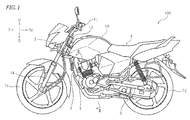
- the vehicle according to the present preferred embodiment is a motorcycle 100, which is one type of the straddled vehicle.
- the vehicle may, however, to a straddled vehicle other than the motorcycle 100.
- the vehicle is not limited to a straddled vehicle.
- the term "straddled vehicle” means a vehicle on which a rider straddles to ride.
- front refers to front, rear, left, right, up, down, above, and below as defined based on the perspective of the rider (not shown) seated on a seat 4 of the motorcycle 100 being at a standstill on a horizontal plane, unless specifically indicated otherwise.
- Reference characters F, Re, L, R, U, and D in the drawings indicate front, rear, left, right, up, and down, respectively.
- the motorcycle 100 has a head pipe 5 and a steering shaft 12 rotatably inserted through the head pipe 5.
- a handlebar 11 is secured to an upper end portion of the steering shaft 12.
- a front fork 14 is secured to a bottom end portion of the steering shaft 12.
- a front wheel 71 is supported at a bottom end portion of the front fork 14.
- a fuel tank 10 is disposed at the rear of the head pipe 5.
- a seat 4 is disposed at the rear of the fuel tank 10. The seat 4 is disposed behind the head pipe 5.
- the head pipe 5 is secured to a body frame 2.
- the body frame 2 extends rearward from the head pipe 5 as viewed from a side view of the vehicle.
- the structure of the body frame 2 is not limited in any way.
- a rear arm 6 is supported swingably on the body frame 2.
- a rear wheel 72 is supported at a rear portion of the rear arm 6.
- a power unit 3 is supported on the body frame 2.
- the power unit 3 is supported non-swingably by the body frame 2. It is also possible, however, that the power unit 3 may be integrated with the rear arm 6 and supported swingably by the body frame 2.
- Fig. 2 is a cross-sectional view taken along line II-II of Fig. 1 , illustrating the power unit 3.
- the power unit 3 includes a cylinder 16 including a cylinder block 13 and a cylinder head 15, and a crankcase 20.
- the cylinder 16 is connected to the crankcase 20.
- the power unit 3 includes a piston 17, a crankshaft 19, a rotary shaft 21, and an output shaft 24.
- the piston 17 is reciprocatably provided in the cylinder 16.
- the crankshaft 19 is connected to the piston 17 via a connecting rod 18.
- the rotary shaft 21 and the output shaft 24 are arranged parallel to the crankshaft 19.
- the power unit 3 also includes a clutch 30, a transmission 40, and an alternator 50.
- the crankshaft 19 is rotatably supported by the crankcase 20 via a bearing 22.
- the crankshaft 19 includes shaft main parts 19A extending linearly and crank webs 19B extending from the shaft main parts 19A in a direction perpendicular to the axial direction.
- the crank webs 19B are connected to each other by a crank pin 19C.
- the connecting rod 18 is connected to the crank pin 19C.
- the alternator 50 is fitted to a left end portion of the crankshaft 19.
- a first gear 23 is provided on a right end portion of the crankshaft 19.
- the transmission 40 includes a plurality of gears 41 provided on the rotary shaft 21, and a plurality of gears 42 provided on the output shaft 24.
- the transmission 40 is a stepped-type transmission.
- the output shaft 24 is a rotary shaft for taking out the mechanical power of the crankshaft 19.
- a sprocket 43 is secured to a left end portion of the output shaft 24.
- another sprocket is secured to the rear wheel 72 (see Fig. 1 ).
- a chain 44 is wrapped around the sprocket 43 and the other sprocket.
- the mechanical power of the output shaft 24 is transmitted via the chain 44 to the rear wheel 72.
- the chain 44 is an example of the power transmission member, the power transmission member is not limited to the chain 44 and may be, for example, a transmission belt or a drive shaft.
- the clutch 30 has a clutch housing 25 supported so as to be rotatable relative to the rotary shaft 21, first clutch plates 26 that rotate with the clutch housing 25, second clutch plates 27 capable of making contact with and separating from the first clutch plates 26, and a clutch boss 28 that rotates with the second clutch plates 27 and also rotates with the rotary shaft 21.
- the clutch housing 25 and the clutch boss 28 are examples of the first clutch member and the second clutch member, respectively. It should be noted, however, that the first clutch member and the second clutch member are not limited to the clutch housing 25 and the clutch boss 28, and their configurations are not limited to specific forms.
- the clutch 30 includes a pressure plate 29 movable in an axial direction of the rotary shaft 21 and a spring 31 for biasing the pressure plate 29 toward the first clutch plates 26 and the second clutch plates 27.
- the first clutch plates 26 and the second clutch plates 27 are pressed against each other by receiving a force from the pressure plate 29. Thereby, the clutch 30 is engaged.
- the clutch 30 is engaged, the first clutch plates 26 and the second clutch plates 27 rotate together to transmit mechanical power from the first clutch plates 26 to the second clutch plates 27.
- the clutch 30 also includes a clutch release mechanism 32 (not shown in Fig. 3 , see Fig. 2 ) for moving the pressure plate 29 away from the first clutch plates 26 and the second clutch plates 27.
- the clutch release mechanism 32 moves the pressure plate 29 away from the first clutch plates 26 and the second clutch plates 27 when the rider pulls a clutch lever, which is not shown, for example.
- the first clutch plates 26 and the second clutch plates 27 separate from each other.
- the first clutch plates 26 slip against the second clutch plates 27, so that the transmission of mechanical power from the first clutch plates 26 to the second clutch plates 27 is cut off. In other words, the clutch 30 is disengaged.
- the clutch housing 25 is provided with a second gear 33 meshing with the first gear 23 of the crankshaft 19. The torque of the crankshaft 19 is transmitted through via the first gear 23 and the second gear 33 to the clutch housing 25. Thus, the clutch housing 25 rotates with the crankshaft 19.
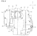
- Fig. 4 is a plan view of the crankcase 20.
- the crankcase 20 includes a first case member 51, a second case member 52, a first cover 46, and a second cover 47.
- the first case member 51 and the second case member 52 are secured to each other by bolts 48.
- the first cover 46 is secured to the first case member 51 by bolts 49.
- the second cover 47 is secured to the second case member 52 by bolts 53.
- the first cover 46 is disposed over a side of the alternator 50.
- the second cover 47 is provided over a side of the clutch 30.
- the second cover 47 covers a side of the clutch 30.
- the second case member 52 includes a partition wall 54.
- the partition wall 54 is provided inside the crankcase 20. At least a portion of the partition wall 54 is provided between the crank webs 19B and the clutch 30 with respect to the axial direction of the crankshaft 19.
- the partition wall 54 has a through bore 55 through which the rotary shaft 21 passes.
- the partition wall 54 includes a vertical wall 54A extending in a radial direction of the rotary shaft 21, and a lateral wall 54B extending from an upper portion of the vertical wall 54A toward the crank webs 19B with respect to the axial direction of the rotary shaft 21.
- crankshaft 19 and the rotary shaft 21 are parallel to each other herein, so the axial direction and the radial direction of the rotary shaft 21 respectively have the same meaning as the axial direction and the radial direction of the crankshaft 19 herein.
- the lateral wall 54B is spaced apart from an outer circumferential wall 52a of the second case member 52. It should be noted, however, that the above-described configuration of the partition wall 54 is merely one example and is not intended to be limiting.
- the rotary shaft 21 is supported by a bearing 34.
- the bearing 34 is interposed between the rotary shaft 21 and the crankcase 20.
- the rotary shaft 21 is rotatably supported by the crankcase 20 via a bearing 34.
- the bearing 34 is interposed between the rotary shaft 21 and the second case member 52.
- the bearing 34 is fitted into the through bore 55 of the partition wall 54.
- This configuration is, however, merely illustrative.
- another bearing 35 is provided on an end portion of the rotary shaft 21 opposite the one on which the clutch 30 is provided.
- the other bearing 35 is also interposed between the rotary shaft 21 and the crankcase 20.
- a gear 41 of the transmission 40 is disposed between the bearing 34 and the bearing 35 with respect to the axial direction of the rotary shaft 21.
- each of the bearings 34 and 35 is formed by a ball bearing.
- the bearing 34 includes a (sealing) structure 34a for sealing oil.
- the bearing 34 is formed by what is called a sealed bearing. It should be noted, however, that the type of the bearings 34 and 35 is not limited to a specific type.
- the clutch housing 25 is spaced apart from the bearing 34 with respect to the axial direction of the rotary shaft 21.
- a collar 38 is disposed between the bearing 34 and the clutch housing 25, with respect to the axial direction of the rotary shaft 21.
- the rotary shaft 21 is inserted through the collar 38.
- the collar 38 may or may not be able to rotate relative to the rotary shaft 21.
- the collar 38 may be configured to rotate together the rotary shaft 21.
- the clutch housing 25 has a bore 36 through which the rotary shaft 21 is inserted.
- the inner circumferential surface 36a of the bore 36 faces the outer circumferential surface 21a of the rotary shaft 21.
- the clutch housing 25 is supported so as to be rotatable relative to the rotary shaft 21, and a clearance gap 37 is formed between the outer circumferential surface 21 a of the rotary shaft 21 and the inner circumferential surface 36a of the bore 36.
- the clutch housing 25 While the clutch 30 is being disengaged, the clutch housing 25 rotates relative to the rotary shaft 21. At that time, friction arises between the outer circumferential surface 21a of the rotary shaft 21 and the inner circumferential surface 36a of the bore 36. For this reason, it is necessary to supply oil into the clearance gap 37.
- the present preferred embodiment provides an oil catch member 39 for catching oil and supplies the oil collected by the oil catch member 39 to the clearance gap 37.
- the oil catch member 39 is disposed radially outward of the rotary shaft 21 relative to the outer circumferential surface 21 a of the rotary shaft 21.
- the oil catch member 39 has an inner circumferential surface 39a spaced apart from the outer circumferential surface 21a of the rotary shaft 21. At least a portion of the oil catch member 39 is disposed between the bearing 34 and the clutch housing 25 with respect to the axial direction of the rotary shaft 21.
- At least a portion of the oil catch member 39 is disposed, with respect to the axial direction of the rotary shaft 21, at a position closer to the clutch housing 25 relative to an end portion of the bearing 34 that faces the clutch housing 25, the position also being closer to the bearing 34 relative to an end portion of the clutch housing 25 that faces the bearing 34.
- At least a portion of the oil catch member 39 is disposed radially outward of the rotary shaft 21 relative to the collar 38.
- the entire oil catch member 39 is disposed radially outward of the rotary shaft 21 relative to the collar 38.
- the collar 38 is disposed between the rotary shaft 21 and the oil catch member 39 with respect to the radial direction of the rotary shaft 21. Such an arrangement is, however, merely exemplary.
- the oil catch member 39 is formed integrally with the second case member 52 in the present preferred embodiment, although it may be a separate component.
- the oil catch member 39 is formed integrally with the second case member 52 by casting, for example.
- the oil catch member 39 is provided on the partition wall 54.
- the oil catch member 39 is integrated with the partition wall 54.
- the oil catch member 39 defines an oil reservoir space 45 for storing oil.
- the oil reservoir space 45 is formed between the inner circumferential surface 39a of the oil catch member 39 and the outer circumferential surface 21a of the rotary shaft 21.
- at least a portion of the collar 38 is disposed in the oil reservoir space 45.
- the oil reservoir space 45 is in communication with the clearance gap 37 between the outer circumferential surface 21 a of the rotary shaft 21 and the inner circumferential surface 36a of the bore 36.
- the oil reservoir space 45 is allowed to communicate with the clearance gap 37 through a clearance gap 38b between the outer circumferential surface 21a of the rotary shaft 21 and an inner circumferential surface 38a of the collar 38. It should be noted, however, that the form of communication between the oil reservoir space 45 and the clearance gap 37 is not limited in any way.
- the oil reservoir space 45 is configured to be able to supply oil to the clearance gap 37.
- the length of the oil reservoir space 45 along the axial direction of the rotary shaft 21 be, but not be limited to, greater than the thickness of the first clutch plate 26.
- the length of the oil reservoir space 45 along the axial direction of the rotary shaft 21 may be two times or more, or three times or more, greater than the thickness of the first clutch plate 26.
- the length of the oil reservoir space 45 along the axial direction of the rotary shaft 21 may be equal to or greater than the total thickness of all the first clutch plates 26 provided in the clutch 30, or it may be equal to or greater than the total thickness of all the first clutch plates 26 and all the second clutch plates 27 provided in the clutch 30.
- the length of the oil reservoir space 45 along the axial direction of the rotary shaft 21 may be equal to or greater than the length of the bearing 34 along the axial direction of the rotary shaft 21. Increasing the length of the oil reservoir space 45 along the axial direction of the rotary shaft 21 allows the oil reservoir space 45 to have a large space.
- the depth of the oil reservoir space 45 may vary depending on the positions with respect to the axial direction of the rotary shaft 21.
- the term "the depth of the oil reservoir space 45" means a distance between the outer circumferential surface 21 a of the rotary shaft 21 and the inner circumferential surface 39a of the oil catch member 39.
- the oil reservoir space 45 has a first depth D1 and a second depth D2 that is greater than the first depth D1.
- the collar 38 is indicated by a virtual line in Fig. 5 .
- the second depth D2 is the maximum depth in the present preferred embodiment.
- the maximum depth of the oil reservoir space 45 is greater than the thickness of the first clutch plate 26.
- the maximum depth of the oil reservoir space 45 may be two times or more, or three times or more, greater than the thickness of the first clutch plate 26. Increasing the maximum depth of the oil reservoir space 45 allows the oil reservoir space 45 to have a large space. It should be noted, however, that the value of the maximum depth of the oil reservoir space 45 is not limited to a specific value.
- Fig. 6 is a view showing the second case member 52 viewed from the right
- Fig. 7 is a view showing the second case member 52 viewed from the left.
- the oil catch member 39 is indicated by a hatched region in order to emphasize the arrangement and shape of the oil catch member 39. Note that the hatched region in Fig. 6 does not indicate the cross section.
- the oil catch member 39 is formed in a circular arc shape when viewed in the axial direction of the rotary shaft 21.
- the angle ⁇ of the inner circumferential surface 39a of the oil catch member 39 about the axial center 21c of the rotary shaft 21 may be, but is not limited to be, 120 degrees or greater, or 180 degrees or greater, for example. In the present preferred embodiment, the angle ⁇ is 260 degrees.
- a first circumferential end portion 39c and a second circumferential end portion 39d of the oil catch member 39 are positioned upward relative to the axial center 21c of the rotary shaft 21.
- the oil catch member 39 is disposed downward relative to the top end 21t of the rotary shaft 21.
- Ribs 56 and 57 are disposed above the oil catch member 39.
- the ribs 56 and 57 are inclined downward toward the oil catch member 39 when viewed in the axial direction of the rotary shaft 21.
- the shapes of the ribs 56 and 57 are not limited.
- the ribs 56 and 57 may be either connected to the outer circumferential wall 52a of the second case member 52 or spaced apart from the outer circumferential wall 52a of the second case member 52.
- the ribs 56 and 57 may be either connected to the oil catch member 39 or spaced apart from the oil catch member 39.
- an upper end portion 56a of the rib 56 is connected to the outer circumferential wall 52a of the second case member 52, while a lower end portion 56b of the rib 56 is connected to the first end portion 39c of the oil catch member 39.
- An upper end portion 57a of the rib 57 is spaced apart from the outer circumferential wall 52a of the second case member 52, while a lower end portion 57b of the rib 57 is connected to the second end portion 39d of the oil catch member 39.
- the ribs 56 and 57 may be in a linear shape, in a partially bent shape, or in a partially or entirely curved shape.
- the rib 56 is formed in a linear shape.
- the rib 57 is in a partially bent shape.
- the ribs 56 and 57 protrude from the partition wall 54.
- the ribs 56 and 57 protrude from the partition wall 54 toward the clutch 30.
- the ribs 56 and 57 may be either separate components from the partition wall 54, or may be integrally formed with the partition wall 54.
- the ribs 56 and 57 have respective upper surfaces 56c and 57c that are parallel to the axial direction of the rotary shaft 21.
- the ribs 56 and 57 serve to guide oil toward the oil catch member 39.
- an oil introducing member 58 is disposed above the oil catch member 39.
- the oil introducing member 58 is, however, not always necessary, and it may be omitted.
- the oil introducing member 58 is disposed above the rotary shaft 21.
- the oil introducing member 58 is disposed above the collar 38.
- the oil introducing member 58 has an inner circumferential surface 58a positioned radially outward of the rotary shaft 21 relative to the outer circumferential surface 21a of the rotary shaft 21.
- the inner circumferential surface 58a faces the outer circumferential surface 21 a.
- the oil introducing member 58 is disposed between the bearing 34 and the clutch housing 25 with respect to the axial direction of the rotary shaft 21.
- the oil introducing member 58 is disposed, with respect to the axial direction of the rotary shaft 21, at a position closer to the clutch housing 25 relative to an end portion of the bearing 34 that faces the clutch housing 25, the position also being closer to the bearing 34 relative to an end portion of the clutch housing 25 that faces the bearing 34.
- the oil introducing member 58 is spaced apart from the bearing 34.
- An opening 59 is formed between the oil introducing member 58 and the bearing 34 with respect to the axial direction of the rotary shaft 21. Although the details will be described later, the opening 59 serves to introduce oil into the oil reservoir space 45.
- the partition wall 54 divides the internal space of the crankcase 20 into a space 61 adjacent to the crank webs 19B and a space 62 adjacent to the clutch 30.
- a communication port 63 for allowing the space 61 and the space 62 to communicate with each other is formed in a portion of the partition wall 54 that is upward relative to the oil catch member 39.
- the communication port 63 allows the space 61 to the left of the partition wall 54 and the space 62 to the right of the partition wall 54 to communicate with each other.
- the communication port 63 is hatched, in order to emphasize the position and shape of the communication port 63. Note that the hatched region in Fig.
- the communication port 63 is formed in the lateral wall 54B of the partition wall 54.
- the region of the partition wall 54 in which the communication port 63 is to be formed is not limited thereto.
- the communication port 63 may be formed in the vertical wall 54A of the partition wall 54.
- At least a portion of the communication port 63 is positioned upward relative to the oil catch member 39.
- the entire communication port 63 is positioned upward relative to the oil catch member 39.
- at least a portion of the communication port 63 is positioned upward relative to the rotary shaft 21.
- the entire communication port 63 is positioned upward relative to the rotary shaft 21.
- at least a portion of the communication port 63 is positioned upward relative to the crankshaft 19.
- the entire communication port 63 is positioned upward relative to the crankshaft 19.
- at least a portion of the communication port 63 is positioned upward relative to the oil introducing member 58.
- the entire communication port 63 is positioned upward relative to the oil introducing member 58.
- At least a portion of the communication port 63 is positioned closer to the crankshaft 19 relative to the axial center 21c of the rotary shaft 21 and positioned closer to the rotary shaft 21 relative to the axial center 19c of the crankshaft 19.
- at least a portion of the communication port 63 is positioned frontward relative to the axial center 21 c of the rotary shaft 21 and rearward relative to the axial center 19c of the crankshaft 19.
- the entire communication port 63 is positioned frontward relative to the axial center 21c of the rotary shaft 21 and rearward relative to the axial center 19c of the crankshaft 19.
- the above-described arrangement of the communication port 63 is merely one example, and is not intended to be limiting.
- reference character M1 indicates the direction of rotation of the crankshaft 19.
- a downward region R1 one in which the crank webs 19B (not shown in Fig. 8 , see Fig. 2 ) of the crankshaft 19 move downward
- an upward region R2 one in which the crank webs 19B (not shown in Fig. 8 , see Fig. 2 ) of the crankshaft 19 move downward
- the other one in which the crank webs 19B move upward is defined as an upward region R2.
- the communication port 63 is positioned in the upward region R2.
- the vertical plane P1 is a plane perpendicular to the horizontal plane.
- the communication port 63 opens downward in a lower surface of the lateral wall 54B of the partition wall 54.
- the communication port 63 is disposed at a position that enables the oil scooped up by the crank webs 19B to easily flow into.
- the above-described arrangement of the communication port 63 is merely one example, and it is also possible to dispose the communication port 63 in the downward region R1.
- the communication port 63 is formed in a quadrangular shape.
- the length 63L of the communication port 63 along the axial direction of the rotary shaft 21 is longer than the length 59L of the opening 59 along the axial direction of the rotary shaft 21.
- the above-described shape and dimensions of the communication port 63 are merely exemplary, and the shape and dimensions of the communication port 63 are not limited to specific shapes or dimensions.
- a portion of the oil that has lubricated the cylinder 16 flows into the crankcase 20.
- a portion of the oil that has lubricated the crankshaft 19 is discharged radially outward of the crankshaft 19.
- oil is stored in the bottom portion of the crankcase 20, and a portion of the oil is scooped up by the crank webs 19B.
- These portions of the oil scatters around within the space 61 in the crankcase 20.
- the oil scattering around in the space 61 is introduced into the communication port 63 by the rotating crank webs 19B, as indicated by the arrow U3.
- the oil that has been introduced into the communication port 63 is guided through the communication port 63 into the space 62. Note that in Fig. 10 , the communication port 63 is hatched so that the communication port 63 can be seen clearly.
- the power unit 3 makes it possible to supply oil from the oil reservoir space 45 formed between the inner circumferential surface 39a of the oil catch member 39 and the outer circumferential surface 21 a of the rotary shaft 21 to the clearance gap 37 between the outer circumferential surface 21a of the rotary shaft 21 and the inner circumferential surface 36a of the bore 36 of the clutch housing 25.
- the oil serves to reduce the frictional resistance between the rotary shaft 21 and the clutch housing 25.
- the oil supply passage for supplying oil to the clearance gap 37 is not formed inside the rotary shaft 21. This enables the rotary shaft 21 to have a smaller diameter.
- the oil supply passage for supplying oil to the clearance gap 37 may be formed inside the rotary shaft 21.
- the oil supply passage inside the rotary shaft 21 may be made smaller. Therefore, the diameter of the rotary shaft 21 can be made small in this case as well.
- the present preferred embodiment makes it possible to prevent an increase in size of the power unit 3 while reducing the frictional resistance of the clutch 30.
- the angle ⁇ of the inner circumferential surface 39a of the oil catch member 39 about the axial center 21c of the rotary shaft 21 is 120 degrees or greater. This allows the oil reservoir space 45 to have a large space. Thus, because the oil reservoir space 45 can store a larger amount of oil, it is possible to supply the oil steadily to the clearance gap 37. As a result, the frictional resistance can be reduced steadily.
- the length of the oil reservoir space 45 along the axial direction of the rotary shaft 21 is greater than the thickness of the first clutch plate 26. Because the oil reservoir space 45 is ensured to have a large space, the oil reservoir space 45 can store a larger amount of oil. Therefore, oil can be supplied steadily to the clearance gap 37, and frictional resistance can be reduced steadily.
- the maximum depth D2 of the oil reservoir space 45 is greater than the thickness S1 of the first clutch plate 26.
- the oil reservoir space 45 can store a large amount of oil. Therefore, oil can be supplied steadily to the clearance gap 37, and frictional resistance can be reduced steadily.
- a collar 38 is disposed between the bearing 34 and the clutch housing 25 in the present preferred embodiment. It does not mean that a portion of the clutch housing 25 is disposed closer to the bearing 34 relative to an end portion of the oil catch member 39 that faces the clutch housing 25. Therefore, the dimension of the clutch housing 25 along the axial direction can be kept small, and accordingly, the size of the clutch housing 25 can be reduced. Moreover, because the dimension of the clutch housing 25 along the axial direction can be kept small, the contact area between the outer circumferential surface 21 a of the rotary shaft 21 and the inner circumferential surface 36a of the bore 36 of the clutch housing 25 can be reduced. As a result, the frictional resistance can be reduced.
- the collar 38 is not always necessary. It is also possible that a portion of the clutch housing 25 is disposed closer to the bearing 34 relative to an end portion of the oil catch member 39 that faces the clutch housing 25. A portion of the clutch housing 25 may form the collar 38.
- the oil stored in a bottom portion of the crankcase 20 is scooped up by the crank webs 19B in association with the rotation of the crankshaft 19, and is sent through the communication port 63 of the partition wall 54 to a region above the oil catch member 39.
- This oil is caught by the oil catch member 39 and is stored in the oil reservoir space 45.
- the oil is stored in the reservoir space 45 steadily. This enables a steady supply of oil to the clearance gap 37, thus resulting in a steady reduction in the frictional resistance.
- the oil catch member 39 is formed integrally with the partition wall 54. This reduces the parts count, thus reducing the manufacturing costs of the power unit 3.
- the partition wall 54 includes the vertical wall 54A and the lateral wall 54B (see Fig. 3 ).
- a space for collecting the scattered oil is formed above the lateral wall 54B.
- the scattered oil runs along the lateral wall 54B and the vertical wall 54A, and is guided into the oil reservoir space 45. Therefore, the oil can be stored efficiently in the oil reservoir space 45. This enables a steady supply of oil to the clearance gap 37, resulting in a steady reduction in the frictional resistance.
- the oil introducing member 58 dams up the oil that flows from the bearing 34 toward the clutch housing 25 so as to introduce the oil through the opening 59 into the oil reservoir space 45.
- the oil can be stored efficiently in the oil reservoir space 45. This enables a steady supply of oil to the clearance gap 37, thus resulting in a steady reduction in the frictional resistance.
- the oil located above the oil catch member 39 flows along the ribs 56 and 57 and is guided into the oil catch member 39. Therefore, the oil can be stored efficiently in the oil reservoir space 45. This enables a steady supply of oil to the clearance gap 37, resulting in a steady reduction in the frictional resistance.
- the bearing 34 includes a (sealing) structure 34a for sealing oil. This prevents the oil stored in the oil reservoir space 45 from leaking through the bearing 34. As a result, the oil reservoir space 45 can store the oil stably.
- both the outer circumferential surface 21 a of the rotary shaft 21 and the inner circumferential surface 36a of the bore 36 of the clutch housing 25, which form the clearance gap 37 are flat and smooth surfaces.
- either one or both of the outer circumferential surface 21 a of the rotary shaft 21 and the inner circumferential surface 36a of the bore 36 may have a groove formed therein.
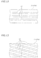
- linear grooves 67 extending in the axial direction may be formed in either one or both of the outer circumferential surface 21 a of the rotary shaft 21 and the inner circumferential surface 36a of the bore 36.
- Fig. 12 linear grooves 67 extending in the axial direction may be formed in either one or both of the outer circumferential surface 21 a of the rotary shaft 21 and the inner circumferential surface 36a of the bore 36.
- spiral grooves 67 may be formed in either one or both of the outer circumferential surface 21a of the rotary shaft 21 and the inner circumferential surface 36a of the bore 36. It should be noted, however, that the grooves 67 are merely one example, and the shape and dimensions thereof are not limited to specific shapes and dimensions. Because the outer circumferential surface 21 a of the rotary shaft 21 and/or the inner circumferential surface 36a of the bore 36 is/are provided with the grooves 67 formed therein, the oil is allowed to easily flow through the clearance gap 37. As a result, the oil stored in the oil reservoir space 45 can be supplied to the clearance gap 37 desirably, so that the frictional resistance can be reduced effectively.
- the rotary shaft 21 is disposed parallel to the crankshaft 19.
- the rotary shaft 21 may be disposed coaxially with the crankshaft 19 and may be formed integrally with the crankshaft 19.
- the clutch 30 is a centrifugal clutch.
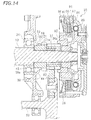
- the clutch 30 has a clutch boss 85 supported so as to be rotatable relative to the rotary shaft 21, first clutch plates 87 that rotate with the clutch boss 85, second clutch plates 88 capable of making contact with and separating from the first clutch plates 87, and a clutch housing 86 that rotates with the second clutch plates 88 and also rotates with the rotary shaft 21.
- the clutch boss 85 and the clutch housing 86 are examples of the first clutch member and the second clutch member, respectively.
- the centrifugal weight 89 moves radially outward, causing the first clutch plates 87 and the second clutch plates 88 to be pressed against each other, so as to bring the clutch 30 into engagement.
- the centrifugal weight 89 moves radially inward, causing the first clutch plates 87 and the second clutch plates 88 to separate from each other, so as to bring the clutch 30 into disengagement.
- the power unit 3 further includes another rotary shaft 80 having a first gear 81.
- the rotary shaft 80 is disposed parallel to the rotary shaft 21.
- the clutch boss 85 includes a second gear 82 meshing with the first gear 81.
- the clutch housing 86 is secured to the rotary shaft 21.
- the second gear 82 has a bore 36 through which the rotary shaft 21 is inserted.
- the outer circumferential surface 21a of the rotary shaft 21 is slidable relative to the inner circumferential surface 36a of the bore 36.
- a clearance gap 37 is formed between the outer circumferential surface 21a of the rotary shaft 21 and the inner circumferential surface 36a of the bore 36.
- the oil reservoir space 45 is formed between the inner circumferential surface 39a of the oil catch member 39 and the outer circumferential surface 21a of the rotary shaft 21.
- the oil reservoir space 45 is in communication with the clearance gap 37.
- the oil in the oil reservoir space 45 is supplied to the clearance gap 37. This serves to reduce the frictional resistance between the rotary shaft 21 and the clutch boss 85.
- No oil supply passage for supplying oil to the clearance gap 37 is formed inside the rotary shaft 21. It is possible, however, that an oil supply passage may be provided inside the rotary shaft 21.
- the rotary shaft 80 is connected to the output shaft 24 via the transmission 40.
- the rest of the configurations are similar to the first preferred embodiment, and therefore a further description thereof will be omitted.
- the present preferred embodiment also makes it possible to obtain the same advantageous effects as obtained in the first preferred embodiment. It is possible to reduce the frictional resistance between the rotary shaft 21 of the clutch 30 and the clutch boss 85 while at the same time prevent an increase in the size of the power unit 3.
Landscapes
- Engineering & Computer Science (AREA)
- General Engineering & Computer Science (AREA)
- Mechanical Engineering (AREA)
- General Details Of Gearings (AREA)
- Hydraulic Clutches, Magnetic Clutches, Fluid Clutches, And Fluid Joints (AREA)
- Sealing Of Bearings (AREA)
Description
- The present invention relates to a power unit and a vehicle equipped with the power unit.
- A power unit equipped with a clutch is conventionally used in vehicles, such as motorcycles, as disclosed in
JP 2014-206203 A JP 2014-206203 A - The clutch housing and the clutch boss each have a bore formed therein. A rotary shaft passes through the bore in the clutch housing and the bore in the clutch boss. The clutch boss is secured to the rotary shaft, so that the clutch boss and the rotary shaft rotate together. The clutch housing is rotatably supported on the rotary shaft, and the clutch housing and the rotary shaft are relatively rotatable. When the clutch housing rotates relative to the rotary shaft, frictional resistance arises between the outer circumferential surface of the rotary shaft and the inner circumferential surface of the bore of the clutch housing. In order to reduce the frictional resistance, oil is supplied to the gap between the outer circumferential surface of the rotary shaft and the inner circumferential surface of the bore of the clutch housing. In the power unit described in
JP 2014-206203 A - However, because the above-described rotary shaft has a large diameter oil passage formed therein, the rotary shaft also inevitably has a large diameter. In addition, in order to supply oil to the oil passage inside the rotary shaft, it is necessary to provide another oil passage in a portion of the power unit other than the rotary shaft, which increases the size of the other portion of the power unit corresponding to the size of the other oil passage. As a consequence, the power unit tends to be larger in size.
- The present invention has been accomplished in view of the foregoing and other problems, and it is an object of the invention to provide a power unit that reduces the frictional resistance between the clutch and the rotary shaft while at the same time prevents an increase in the size thereof, and to provide a vehicle equipped therewith.
- According to the present invention said object is solved by a power unit having the features of
independent claim 1. Preferred embodiments are laid down in the dependent claims. - A power unit according to the present teaching includes a cylinder, a piston reciprocatably provided in the cylinder, a crankshaft connected to the piston via a connecting rod, a rotary shaft having an outer circumferential surface and being capable of being rotated by a driving force of the crankshaft, a clutch attached to the rotary shaft, a crankcase accommodating the crankshaft, the rotary shaft, and the clutch, and a bearing interposed between the rotary shaft and the crankcase. The clutch includes a first clutch member supported so as to be rotatable relative to the rotary shaft, a first clutch plate rotating with the first clutch member, a second clutch plate capable of making contact with and separating from the first clutch plate, and a second clutch member rotating with the second clutch plate and also rotating with the rotary shaft. The first clutch member includes a bore having an inner circumferential surface facing the outer circumferential surface of the rotary shaft and through which the rotary shaft is inserted. The power unit further includes an oil catch member positioned radially outward of the rotary shaft relative to the outer circumferential surface of the rotary shaft and spaced apart from the outer circumferential surface. At least a portion of the oil catch member is disposed, with respect to the axial direction of the rotary shaft, at a position closer to the first clutch member relative to an end portion of the bearing that faces the first clutch member, the position also being closer to the bearing relative to an end portion of the first clutch member that faces the bearing. An oil reservoir space is formed between the inner circumferential surface of the oil catch member and the outer circumferential surface of the rotary shaft, the oil reservoir space storing oil and communicating with a clearance gap between the outer circumferential surface of the rotary shaft and the inner circumferential surface of the bore of the first clutch member.
- In the just-described power unit, oil is supplied from the oil reservoir space formed between the inner circumferential surface of the oil catch member and the outer circumferential surface of the rotary shaft to the clearance gap between the outer circumferential surface of the rotary shaft and the inner circumferential surface of the bore of the first clutch member. The oil serves to reduce the frictional resistance between the outer circumferential surface of the rotary shaft and the inner circumferential surface of the bore of the first clutch member. With the just-described power unit, it is not necessary to form a large diameter oil supply passage inside the rotary shaft in order to supply oil to the clearance gap. Therefore, in the case where an oil supply passage needs to be formed inside the rotary shaft, the diameter of the oil supply passage can be made small. Or, no oil supply passage needs to be formed inside the rotary shaft. This enables the rotary shaft to have a smaller diameter. In addition, with the just-described power unit, a large diameter oil passage for supplying oil to the oil supply passage inside the rotary shaft does not need to be provided in the other portion of the power unit. For the reasons described above, the just-described power unit makes it possible to prevent an increase in size of the power unit while reducing the frictional resistance of the clutch.
- In a preferable embodiment, the inner circumferential surface of the oil catch member has an angle of 120 degrees or greater about the axial center of the rotary shaft.
- When the angle of the inner circumferential surface of the oil catch member is sufficiently great as in the just-described preferred embodiment, the oil reservoir space is ensured to be sufficiently large. Thus, because the oil reservoir space can store a large amount of oil, it is possible to supply the oil steadily to the clearance gap between the outer circumferential surface of the rotary shaft and the inner circumferential surface of the bore of the first clutch member. As a result, the frictional resistance can be reduced steadily.
- In another preferred embodiment, a length of the oil reservoir space along the axial direction of the rotary shaft is greater than a thickness of the first clutch plate.
- When the oil reservoir space has a sufficient length along the axial direction of the rotary shaft as in the just-described preferred embodiment, the oil reservoir space can store a large amount of oil. This enables a steady supply of oil to the clearance gap between the outer circumferential surface of the rotary shaft and the inner circumferential surface of the bore of the first clutch member, resulting in a steady reduction in the frictional resistance therebetween.
- In another preferred embodiment, a maximum depth of the oil reservoir space is greater than a thickness of the first clutch plate.
- When the maximum depth of the oil reservoir space is sufficiently deep as in the just-described preferred embodiment, the oil reservoir space can store a large amount of oil. This enables a steady supply of oil to the clearance gap between the outer circumferential surface of the rotary shaft and the inner circumferential surface of the bore of the first clutch member, resulting in a steady reduction in the frictional resistance therebetween.
- In another preferred embodiment, the power unit further includes a collar disposed between the bearing and the first clutch member with respect to the axial direction of the rotary shaft and through which the rotary shaft is inserted. At least a portion of the oil catch member is disposed radially outward of the rotary shaft relative to the collar.
- In the just-described preferred embodiment, a collar is disposed between the bearing and the first clutch member. It does not mean that a portion of the first clutch member is disposed closer to the bearing relative to an end portion of the oil catch member that faces the first clutch member. Therefore, the dimension of the first clutch member along the axial direction can be kept small, and accordingly, the size of the first clutch member can be reduced. Moreover, because the dimension of the first clutch member along the axial direction can be kept small, the contact area between the outer circumferential surface of the rotary shaft and the inner circumferential surface of the bore of the first clutch member can be reduced. As a result, the frictional resistance can be reduced.
- In another preferred embodiment, the crankshaft includes a shaft main part extending linearly and a crank web extending in a direction perpendicular to the axial direction. The power unit further includes a partition wall provided in the crankcase, at least a portion of the partition wall being provided between the crank web and the clutch with respect to the axial direction of the crankshaft, and the partition wall having a through bore through which the rotary shaft is inserted. The bearing is fitted in the through bore of the partition wall. A communication port is formed in a portion of the partition wall that is located between the oil catch member and the cylinder, so that when the power unit is mounted on a vehicle, upward relative to the oil catch member, the communication port allowing a space, defined by the partition wall, that is adjacent to the crank web and a space, defined by the partition wall, that is adjacent to the clutch to communicate with each other.
- In the just-described preferred embodiment, the oil stored in a bottom portion of the crankcase is scooped up by the crank web in association with the rotation of the crankshaft and is sent through the communication port of the partition wall to a region above the oil catch member. This oil is caught by the oil catch member and is stored in the oil reservoir space. As a result, the oil is stored in the reservoir space steadily. This enables a steady supply of oil to the clearance gap between the outer circumferential surface of the rotary shaft and the inner circumferential surface of the bore of the first clutch member, resulting in a steady reduction in the frictional resistance therebetween.
- In another preferred embodiment, the oil catch member is formed integrally with the partition wall.
- The just-described embodiment reduces the parts count, thus lowering the manufacturing costs of the power unit.
- In another preferred embodiment, the partition wall includes a vertical (first) wall extending in a radial direction of the crankshaft, and a lateral (second) wall extending from an upper (when the power unit is mounted on a vehicle) portion of the vertical wall toward the crank web with respect to an axial direction of the crankshaft. The (vertical) first wall and the (lateral) second wall the partition wall are substantially perpendicular to each other.
- In the just-described preferred embodiment, a space for collecting the scattered oil is formed above the lateral wall. The scattered oil runs along the lateral wall and the vertical wall, and is guided into the oil reservoir space. Therefore, the oil can be stored efficiently in the oil reservoir space. This enables a steady supply of oil to the clearance gap between the outer circumferential surface of the rotary shaft and the inner circumferential surface of the bore of the first clutch member, thus resulting in a steady reduction in the frictional resistance therebetween.
- In another preferred embodiment, the power unit further includes an oil introducing member including an inner circumferential surface positioned radially outward of the rotary shaft relative to the outer circumferential surface of the rotary shaft, and disposed, when the power unit is mounted on a vehicle, above the oil catch member. The oil introducing member is disposed, with respect to the axial direction of the rotary shaft, at a position closer to the first clutch member relative to an end portion of the bearing that faces the first clutch member, the position also being closer to the bearing relative to an end portion of the first clutch member that faces the bearing, the oil introducing member being spaced apart from the bearing. An opening for introducing oil into the oil reservoir space is formed between the oil introducing member and the oil reservoir space with respect to the axial direction of the rotary shaft.
- In the just-mentioned preferred embodiment, the oil introducing member dams up the oil that flows from the bearing toward the first clutch member so as to introduce the oil through the opening into the oil reservoir space. The oil can be stored efficiently in the oil reservoir space. This enables a steady supply of oil to the clearance gap between the outer circumferential surface of the rotary shaft and the inner circumferential surface of the bore of the first clutch member, resulting in a steady reduction in the frictional resistance therebetween.
- In another preferred embodiment, the power unit further includes a rib disposed between the bearing and the first clutch member with respect to the axial direction of the rotary shaft and inclined downward toward the oil catch member.
- In the just-described preferred embodiment, the oil located above the oil catch member flows along the rib and is guided into the oil catch member. The oil can be stored efficiently in the oil reservoir space. This enables a steady supply of oil to the clearance gap between the outer circumferential surface of the rotary shaft and the inner circumferential surface of the bore of the first clutch member, resulting in a steady reduction in the frictional resistance therebetween.
- In another preferred embodiment, the bearing includes a sealing structure for sealing oil.
- The just-described preferred embodiment prevents the oil stored in the oil reservoir space from leaking through the bearing. As a result, the oil reservoir space can store the oil stably.
- In another preferred embodiment, the outer circumferential surface of the rotary shaft and/or the inner circumferential surface of the bore of the first clutch member is/are provided with a groove.
- The just-described preferred embodiment allows the oil to easily flow through the clearance gap between the outer circumferential surface of the rotary shaft and the inner circumferential surface of the bore of the first clutch member. As a result, the oil stored in the oil reservoir space can be supplied to the clearance gap desirably, so that the frictional resistance can be reduced effectively.
- In another preferred embodiment, the power unit includes a first gear provided on the crankshaft. The rotary shaft is disposed parallel to the crankshaft. The first clutch member includes a second gear meshing with the first gear. The second clutch member is secured to the rotary shaft. The power unit further includes an output shaft disposed parallel to the rotary shaft, and a transmission coupled to the rotary shaft and the output shaft.
- The just-described preferred embodiment makes it possible to obtain the foregoing advantageous effects with the power unit in which the rotary shaft is disposed parallel to the crankshaft.
- In another preferred embodiment, the rotary shaft is disposed coaxially with the crankshaft, and is formed integrally with the crankshaft. The power unit further includes another rotary shaft disposed parallel to the rotary shaft and including a first gear. The first clutch member includes a second gear meshing with the first gear. The second clutch member is secured to the rotary shaft.
- The just-described preferred embodiment makes it possible to obtain the foregoing advantageous effects with the power unit in which the rotary shaft is disposed coaxially with the crankshaft.
- A vehicle according to the present teaching may be a vehicle including one of the foregoing power units.
- The present teaching makes it possible to provide a power unit that reduces the frictional resistance between the clutch and the rotary shaft while at the same time prevents an increase in the size thereof, and to provide a vehicle equipped therewith.
-
- [
Fig. 1] Fig. 1 is a side view illustrating a motorcycle according to a preferred embodiment. - [
Fig. 2] Fig. 2 is a cross-sectional view of a power unit according to a first preferred embodiment, taken along line II-II ofFig. 1 . - [
Fig. 3] Fig. 3 is a cross-sectional view illustrating a clutch, a rotary shaft, and so forth. - [
Fig. 4] Fig. 4 is a plan view of a crankcase. - [
Fig. 5] Fig. 5 is a partially enlarged cross-sectional view of a rotary shaft and an oil catch member. - [
Fig. 6] Fig. 6 is a side view illustrating a right side face of a second case member. - [
Fig. 7] Fig. 7 is a side view illustrating a left side face of the second case member. - [
Fig. 8] Fig. 8 is a perspective view illustrating a portion of the left side face of the second case member. - [
Fig. 9] Fig. 9 is a perspective view illustrating a portion of the right side face of the second case member. - [
Fig. 10] Fig. 10 is a perspective view illustrating a portion of the left side face of the second case member, which illustrates oil flow. - [
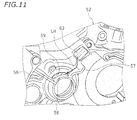
Fig. 11] Fig. 11 is a perspective view illustrating a portion of the right side face of the second case member, which illustrates oil flow. - [
Fig. 12] Fig. 12 is a view illustrating an example of an outer circumferential surface of the rotary shaft and/or an inner circumferential surface of a bore of the clutch housing. - [
Fig. 13] Fig. 13 is a view illustrating another example of an outer circumferential surface of the rotary shaft and/or an inner circumferential surface of a bore of the clutch housing. - [
Fig. 14] Fig. 14 is a cross-sectional view illustrating a portion of a power unit according to a second preferred embodiment. - Hereinbelow, one preferred embodiment will be described with reference to the drawings. As illustrated in
Fig. 1 , a vehicle according to the present preferred embodiment is a straddled vehicle. The vehicle according to the present preferred embodiment is amotorcycle 100, which is one type of the straddled vehicle. The vehicle may, however, to a straddled vehicle other than themotorcycle 100. In addition, the vehicle is not limited to a straddled vehicle. Note that the term "straddled vehicle" means a vehicle on which a rider straddles to ride. - In the following description, the terms "front," "rear," "left," "right," "up," "up," "down," "above," and "below "respectively refer to front, rear, left, right, up, down, above, and below as defined based on the perspective of the rider (not shown) seated on a seat 4 of the
motorcycle 100 being at a standstill on a horizontal plane, unless specifically indicated otherwise. Reference characters F, Re, L, R, U, and D in the drawings indicate front, rear, left, right, up, and down, respectively. The terms used to locate elements on thepower unit 3 such as "front," "rear," "left," "right," "up," "down," "above" and "down" of theengine 3 respectively refer to front, rear, left, right, up, down, above, and below as they would normally understood when thepower unit 3 is mounted on themotorcycle 100 being at a standstill on a horizontal plane. - As illustrated in
Fig. 1 , themotorcycle 100 has ahead pipe 5 and a steeringshaft 12 rotatably inserted through thehead pipe 5. A handlebar 11 is secured to an upper end portion of the steeringshaft 12. Afront fork 14 is secured to a bottom end portion of the steeringshaft 12. Afront wheel 71 is supported at a bottom end portion of thefront fork 14. Afuel tank 10 is disposed at the rear of thehead pipe 5. A seat 4 is disposed at the rear of thefuel tank 10. The seat 4 is disposed behind thehead pipe 5. Thehead pipe 5 is secured to abody frame 2. Thebody frame 2 extends rearward from thehead pipe 5 as viewed from a side view of the vehicle. The structure of thebody frame 2 is not limited in any way. A rear arm 6 is supported swingably on thebody frame 2. Arear wheel 72 is supported at a rear portion of the rear arm 6. - A
power unit 3 is supported on thebody frame 2. In the present preferred embodiment, thepower unit 3 is supported non-swingably by thebody frame 2. It is also possible, however, that thepower unit 3 may be integrated with the rear arm 6 and supported swingably by thebody frame 2. - Next, the structure of the
power unit 3 will be described.Fig. 2 is a cross-sectional view taken along line II-II ofFig. 1 , illustrating thepower unit 3. As illustrated inFig. 2 , thepower unit 3 includes acylinder 16 including acylinder block 13 and acylinder head 15, and acrankcase 20. Thecylinder 16 is connected to thecrankcase 20. - The
power unit 3 includes apiston 17, acrankshaft 19, arotary shaft 21, and anoutput shaft 24. Thepiston 17 is reciprocatably provided in thecylinder 16. Thecrankshaft 19 is connected to thepiston 17 via a connectingrod 18. Therotary shaft 21 and theoutput shaft 24 are arranged parallel to thecrankshaft 19. Thepower unit 3 also includes a clutch 30, atransmission 40, and analternator 50. - The
crankshaft 19 is rotatably supported by thecrankcase 20 via abearing 22. Thecrankshaft 19 includes shaftmain parts 19A extending linearly and crankwebs 19B extending from the shaftmain parts 19A in a direction perpendicular to the axial direction. The crankwebs 19B are connected to each other by a crank pin 19C. The connectingrod 18 is connected to the crank pin 19C. Thealternator 50 is fitted to a left end portion of thecrankshaft 19. Afirst gear 23 is provided on a right end portion of thecrankshaft 19. - The
transmission 40 includes a plurality ofgears 41 provided on therotary shaft 21, and a plurality ofgears 42 provided on theoutput shaft 24. Thetransmission 40 is a stepped-type transmission. - The
output shaft 24 is a rotary shaft for taking out the mechanical power of thecrankshaft 19. In the present preferred embodiment, asprocket 43 is secured to a left end portion of theoutput shaft 24. Although not shown in the drawings, another sprocket is secured to the rear wheel 72 (seeFig. 1 ). Achain 44 is wrapped around thesprocket 43 and the other sprocket. The mechanical power of theoutput shaft 24 is transmitted via thechain 44 to therear wheel 72. Note that although thechain 44 is an example of the power transmission member, the power transmission member is not limited to thechain 44 and may be, for example, a transmission belt or a drive shaft. - Next, the configuration of the clutch 30 will be described with reference to
Fig. 3 . The clutch 30 has aclutch housing 25 supported so as to be rotatable relative to therotary shaft 21, firstclutch plates 26 that rotate with theclutch housing 25, secondclutch plates 27 capable of making contact with and separating from the firstclutch plates 26, and aclutch boss 28 that rotates with the secondclutch plates 27 and also rotates with therotary shaft 21. Theclutch housing 25 and theclutch boss 28 are examples of the first clutch member and the second clutch member, respectively. It should be noted, however, that the first clutch member and the second clutch member are not limited to theclutch housing 25 and theclutch boss 28, and their configurations are not limited to specific forms. - The clutch 30 includes a
pressure plate 29 movable in an axial direction of therotary shaft 21 and aspring 31 for biasing thepressure plate 29 toward the firstclutch plates 26 and the secondclutch plates 27. The firstclutch plates 26 and the secondclutch plates 27 are pressed against each other by receiving a force from thepressure plate 29. Thereby, the clutch 30 is engaged. When the clutch 30 is engaged, the firstclutch plates 26 and the secondclutch plates 27 rotate together to transmit mechanical power from the firstclutch plates 26 to the secondclutch plates 27. - The clutch 30 also includes a clutch release mechanism 32 (not shown in
Fig. 3 , seeFig. 2 ) for moving thepressure plate 29 away from the firstclutch plates 26 and the secondclutch plates 27. Theclutch release mechanism 32 moves thepressure plate 29 away from the firstclutch plates 26 and the secondclutch plates 27 when the rider pulls a clutch lever, which is not shown, for example. When thepressure plate 29 moves away from the firstclutch plates 26 and the secondclutch plates 27, the firstclutch plates 26 and the secondclutch plates 27 separate from each other. Thus, the firstclutch plates 26 slip against the secondclutch plates 27, so that the transmission of mechanical power from the firstclutch plates 26 to the secondclutch plates 27 is cut off. In other words, the clutch 30 is disengaged. - The
clutch housing 25 is provided with asecond gear 33 meshing with thefirst gear 23 of thecrankshaft 19. The torque of thecrankshaft 19 is transmitted through via thefirst gear 23 and thesecond gear 33 to theclutch housing 25. Thus, theclutch housing 25 rotates with thecrankshaft 19. -
Fig. 4 is a plan view of thecrankcase 20. As illustrated inFig. 4 , thecrankcase 20 includes afirst case member 51, asecond case member 52, afirst cover 46, and asecond cover 47. Thefirst case member 51 and thesecond case member 52 are secured to each other bybolts 48. Thefirst cover 46 is secured to thefirst case member 51 bybolts 49. Thesecond cover 47 is secured to thesecond case member 52 bybolts 53. As illustrated inFig. 2 , thefirst cover 46 is disposed over a side of thealternator 50. Thesecond cover 47 is provided over a side of the clutch 30. Thesecond cover 47 covers a side of the clutch 30. - As illustrated in
Fig. 2 , thesecond case member 52 includes apartition wall 54. Thepartition wall 54 is provided inside thecrankcase 20. At least a portion of thepartition wall 54 is provided between thecrank webs 19B and the clutch 30 with respect to the axial direction of thecrankshaft 19. Thepartition wall 54 has a throughbore 55 through which therotary shaft 21 passes. As illustrated inFig. 3 , thepartition wall 54 includes avertical wall 54A extending in a radial direction of therotary shaft 21, and alateral wall 54B extending from an upper portion of thevertical wall 54A toward thecrank webs 19B with respect to the axial direction of therotary shaft 21. Note that thecrankshaft 19 and therotary shaft 21 are parallel to each other herein, so the axial direction and the radial direction of therotary shaft 21 respectively have the same meaning as the axial direction and the radial direction of thecrankshaft 19 herein. Thelateral wall 54B is spaced apart from an outercircumferential wall 52a of thesecond case member 52. It should be noted, however, that the above-described configuration of thepartition wall 54 is merely one example and is not intended to be limiting. - As illustrated in
Fig. 3 , therotary shaft 21 is supported by abearing 34. Thebearing 34 is interposed between therotary shaft 21 and thecrankcase 20. Therotary shaft 21 is rotatably supported by thecrankcase 20 via abearing 34. In the present preferred embodiment, thebearing 34 is interposed between therotary shaft 21 and thesecond case member 52. Thebearing 34 is fitted into the throughbore 55 of thepartition wall 54. This configuration is, however, merely illustrative. In addition, as illustrated inFig. 2 , another bearing 35 is provided on an end portion of therotary shaft 21 opposite the one on which the clutch 30 is provided. Theother bearing 35 is also interposed between therotary shaft 21 and thecrankcase 20. Agear 41 of thetransmission 40 is disposed between the bearing 34 and thebearing 35 with respect to the axial direction of therotary shaft 21. - In the present preferred embodiment, each of the
bearings bearing 34 includes a (sealing)structure 34a for sealing oil. Thebearing 34 is formed by what is called a sealed bearing. It should be noted, however, that the type of thebearings - As illustrated in
Fig. 3 , theclutch housing 25 is spaced apart from the bearing 34 with respect to the axial direction of therotary shaft 21. Acollar 38 is disposed between the bearing 34 and theclutch housing 25, with respect to the axial direction of therotary shaft 21. Therotary shaft 21 is inserted through thecollar 38. Thecollar 38 may or may not be able to rotate relative to therotary shaft 21. Thecollar 38 may be configured to rotate together therotary shaft 21. - As illustrated in
Fig. 3 , theclutch housing 25 has abore 36 through which therotary shaft 21 is inserted. The innercircumferential surface 36a of thebore 36 faces the outercircumferential surface 21a of therotary shaft 21. As described previously, theclutch housing 25 is supported so as to be rotatable relative to therotary shaft 21, and aclearance gap 37 is formed between the outercircumferential surface 21 a of therotary shaft 21 and the innercircumferential surface 36a of thebore 36. While the clutch 30 is being disengaged, theclutch housing 25 rotates relative to therotary shaft 21. At that time, friction arises between the outercircumferential surface 21a of therotary shaft 21 and the innercircumferential surface 36a of thebore 36. For this reason, it is necessary to supply oil into theclearance gap 37. - Accordingly, the present preferred embodiment provides an
oil catch member 39 for catching oil and supplies the oil collected by theoil catch member 39 to theclearance gap 37. Theoil catch member 39 is disposed radially outward of therotary shaft 21 relative to the outercircumferential surface 21 a of therotary shaft 21. Theoil catch member 39 has an innercircumferential surface 39a spaced apart from the outercircumferential surface 21a of therotary shaft 21. At least a portion of theoil catch member 39 is disposed between the bearing 34 and theclutch housing 25 with respect to the axial direction of therotary shaft 21. At least a portion of theoil catch member 39 is disposed, with respect to the axial direction of therotary shaft 21, at a position closer to theclutch housing 25 relative to an end portion of thebearing 34 that faces theclutch housing 25, the position also being closer to thebearing 34 relative to an end portion of theclutch housing 25 that faces thebearing 34. - At least a portion of the
oil catch member 39 is disposed radially outward of therotary shaft 21 relative to thecollar 38. In the present preferred embodiment, the entireoil catch member 39 is disposed radially outward of therotary shaft 21 relative to thecollar 38. Thecollar 38 is disposed between therotary shaft 21 and theoil catch member 39 with respect to the radial direction of therotary shaft 21. Such an arrangement is, however, merely exemplary. - The
oil catch member 39 is formed integrally with thesecond case member 52 in the present preferred embodiment, although it may be a separate component. Theoil catch member 39 is formed integrally with thesecond case member 52 by casting, for example. Theoil catch member 39 is provided on thepartition wall 54. Theoil catch member 39 is integrated with thepartition wall 54. - The
oil catch member 39 defines anoil reservoir space 45 for storing oil. Theoil reservoir space 45 is formed between the innercircumferential surface 39a of theoil catch member 39 and the outercircumferential surface 21a of therotary shaft 21. In the present preferred embodiment, at least a portion of thecollar 38 is disposed in theoil reservoir space 45. Theoil reservoir space 45 is in communication with theclearance gap 37 between the outercircumferential surface 21 a of therotary shaft 21 and the innercircumferential surface 36a of thebore 36. In the present preferred embodiment, theoil reservoir space 45 is allowed to communicate with theclearance gap 37 through aclearance gap 38b between the outercircumferential surface 21a of therotary shaft 21 and an innercircumferential surface 38a of thecollar 38. It should be noted, however, that the form of communication between theoil reservoir space 45 and theclearance gap 37 is not limited in any way. Theoil reservoir space 45 is configured to be able to supply oil to theclearance gap 37. - It is preferable that the length of the
oil reservoir space 45 along the axial direction of therotary shaft 21 be, but not be limited to, greater than the thickness of the firstclutch plate 26. The length of theoil reservoir space 45 along the axial direction of therotary shaft 21 may be two times or more, or three times or more, greater than the thickness of the firstclutch plate 26. The length of theoil reservoir space 45 along the axial direction of therotary shaft 21 may be equal to or greater than the total thickness of all the firstclutch plates 26 provided in the clutch 30, or it may be equal to or greater than the total thickness of all the firstclutch plates 26 and all the secondclutch plates 27 provided in the clutch 30. The length of theoil reservoir space 45 along the axial direction of therotary shaft 21 may be equal to or greater than the length of thebearing 34 along the axial direction of therotary shaft 21. Increasing the length of theoil reservoir space 45 along the axial direction of therotary shaft 21 allows theoil reservoir space 45 to have a large space. - The depth of the
oil reservoir space 45 may vary depending on the positions with respect to the axial direction of therotary shaft 21. The term "the depth of theoil reservoir space 45" means a distance between the outercircumferential surface 21 a of therotary shaft 21 and the innercircumferential surface 39a of theoil catch member 39. As illustrated inFig. 5 , theoil reservoir space 45 has a first depth D1 and a second depth D2 that is greater than the first depth D1. Note that thecollar 38 is indicated by a virtual line inFig. 5 . When the greatest distance among the distances along a radial direction of therotary shaft 21 between the outercircumferential surface 21a of therotary shaft 21 and the innercircumferential surface 39a of theoil catch member 39 is defined as the "maximum depth" of theoil reservoir space 45, the second depth D2 is the maximum depth in the present preferred embodiment. The maximum depth of theoil reservoir space 45 is greater than the thickness of the firstclutch plate 26. The maximum depth of theoil reservoir space 45 may be two times or more, or three times or more, greater than the thickness of the firstclutch plate 26. Increasing the maximum depth of theoil reservoir space 45 allows theoil reservoir space 45 to have a large space. It should be noted, however, that the value of the maximum depth of theoil reservoir space 45 is not limited to a specific value. -
Fig. 6 is a view showing thesecond case member 52 viewed from the right, andFig. 7 is a view showing thesecond case member 52 viewed from the left. It should be noted that inFig. 6 , theoil catch member 39 is indicated by a hatched region in order to emphasize the arrangement and shape of theoil catch member 39. Note that the hatched region inFig. 6 does not indicate the cross section. As illustrated inFig. 6 , theoil catch member 39 is formed in a circular arc shape when viewed in the axial direction of therotary shaft 21. The angle θ of the innercircumferential surface 39a of theoil catch member 39 about theaxial center 21c of therotary shaft 21 may be, but is not limited to be, 120 degrees or greater, or 180 degrees or greater, for example. In the present preferred embodiment, the angle θ is 260 degrees. A firstcircumferential end portion 39c and a secondcircumferential end portion 39d of theoil catch member 39 are positioned upward relative to theaxial center 21c of therotary shaft 21. Theoil catch member 39 is disposed downward relative to thetop end 21t of therotary shaft 21. -
Ribs oil catch member 39. Theribs oil catch member 39 when viewed in the axial direction of therotary shaft 21. The shapes of theribs ribs circumferential wall 52a of thesecond case member 52 or spaced apart from the outercircumferential wall 52a of thesecond case member 52. Theribs oil catch member 39 or spaced apart from theoil catch member 39. Herein, anupper end portion 56a of therib 56 is connected to the outercircumferential wall 52a of thesecond case member 52, while alower end portion 56b of therib 56 is connected to thefirst end portion 39c of theoil catch member 39. Anupper end portion 57a of therib 57 is spaced apart from the outercircumferential wall 52a of thesecond case member 52, while alower end portion 57b of therib 57 is connected to thesecond end portion 39d of theoil catch member 39. Theribs rib 56 is formed in a linear shape. Therib 57 is in a partially bent shape. - The
ribs partition wall 54. Theribs partition wall 54 toward the clutch 30. Theribs partition wall 54, or may be integrally formed with thepartition wall 54. Theribs upper surfaces rotary shaft 21. Theribs oil catch member 39. - As illustrated in
Fig. 3 , anoil introducing member 58 is disposed above theoil catch member 39. Theoil introducing member 58 is, however, not always necessary, and it may be omitted. Theoil introducing member 58 is disposed above therotary shaft 21. Theoil introducing member 58 is disposed above thecollar 38. Theoil introducing member 58 has an innercircumferential surface 58a positioned radially outward of therotary shaft 21 relative to the outercircumferential surface 21a of therotary shaft 21. The innercircumferential surface 58a faces the outercircumferential surface 21 a. Theoil introducing member 58 is disposed between the bearing 34 and theclutch housing 25 with respect to the axial direction of therotary shaft 21. Theoil introducing member 58 is disposed, with respect to the axial direction of therotary shaft 21, at a position closer to theclutch housing 25 relative to an end portion of thebearing 34 that faces theclutch housing 25, the position also being closer to thebearing 34 relative to an end portion of theclutch housing 25 that faces thebearing 34. - The
oil introducing member 58 is spaced apart from thebearing 34. Anopening 59 is formed between theoil introducing member 58 and thebearing 34 with respect to the axial direction of therotary shaft 21. Although the details will be described later, theopening 59 serves to introduce oil into theoil reservoir space 45. - As illustrated in
Fig. 2 , thepartition wall 54 divides the internal space of thecrankcase 20 into aspace 61 adjacent to the crankwebs 19B and aspace 62 adjacent to the clutch 30. As illustrated inFig. 6 , acommunication port 63 for allowing thespace 61 and thespace 62 to communicate with each other is formed in a portion of thepartition wall 54 that is upward relative to theoil catch member 39. In the present preferred embodiment, thecommunication port 63 allows thespace 61 to the left of thepartition wall 54 and thespace 62 to the right of thepartition wall 54 to communicate with each other. InFig. 6 , thecommunication port 63 is hatched, in order to emphasize the position and shape of thecommunication port 63. Note that the hatched region inFig. 6 does not indicate the cross section. Herein, thecommunication port 63 is formed in thelateral wall 54B of thepartition wall 54. However, the region of thepartition wall 54 in which thecommunication port 63 is to be formed is not limited thereto. Thecommunication port 63 may be formed in thevertical wall 54A of thepartition wall 54. - At least a portion of the
communication port 63 is positioned upward relative to theoil catch member 39. Herein, theentire communication port 63 is positioned upward relative to theoil catch member 39. In addition, at least a portion of thecommunication port 63 is positioned upward relative to therotary shaft 21. Herein, theentire communication port 63 is positioned upward relative to therotary shaft 21. Moreover, at least a portion of thecommunication port 63 is positioned upward relative to thecrankshaft 19. Herein, theentire communication port 63 is positioned upward relative to thecrankshaft 19. Furthermore, at least a portion of thecommunication port 63 is positioned upward relative to theoil introducing member 58. Herein, theentire communication port 63 is positioned upward relative to theoil introducing member 58. - At least a portion of the
communication port 63 is positioned closer to thecrankshaft 19 relative to theaxial center 21c of therotary shaft 21 and positioned closer to therotary shaft 21 relative to theaxial center 19c of thecrankshaft 19. In addition, at least a portion of thecommunication port 63 is positioned frontward relative to theaxial center 21 c of therotary shaft 21 and rearward relative to theaxial center 19c of thecrankshaft 19. Herein, theentire communication port 63 is positioned frontward relative to theaxial center 21c of therotary shaft 21 and rearward relative to theaxial center 19c of thecrankshaft 19. However, the above-described arrangement of thecommunication port 63 is merely one example, and is not intended to be limiting. - In
Fig. 8 , reference character M1 indicates the direction of rotation of thecrankshaft 19. Of the two regions R1 and R2 divided by a vertical plane P1 through theaxial center 19c of thecrankshaft 19, as shown inFig. 8 , one in which thecrank webs 19B (not shown inFig. 8 , seeFig. 2 ) of thecrankshaft 19 move downward is defined as a downward region R1, while the other one in which thecrank webs 19B move upward is defined as an upward region R2. Thecommunication port 63 is positioned in the upward region R2. Note that the vertical plane P1 is a plane perpendicular to the horizontal plane. Thecommunication port 63 opens downward in a lower surface of thelateral wall 54B of thepartition wall 54. As a result, the oil scooped up by thecrank webs 19B (indicated by thearrow 63F inFig. 8 ) can easily flow into thecommunication port 63. Thecommunication port 63 is disposed at a position that enables the oil scooped up by thecrank webs 19B to easily flow into. However, the above-described arrangement of thecommunication port 63 is merely one example, and it is also possible to dispose thecommunication port 63 in the downward region R1. - As illustrated in
Fig. 9 , thecommunication port 63 is formed in a quadrangular shape. Thelength 63L of thecommunication port 63 along the axial direction of therotary shaft 21 is longer than thelength 59L of theopening 59 along the axial direction of therotary shaft 21. However, the above-described shape and dimensions of thecommunication port 63 are merely exemplary, and the shape and dimensions of thecommunication port 63 are not limited to specific shapes or dimensions. - The configuration of the
power unit 3 has been described above. Next, the following describes the operation of supplying oil to theclearance gap 37 between the outercircumferential surface 21a of therotary shaft 21 and the innercircumferential surface 36a of thebore 36 of theclutch housing 25. - As indicated by the arrows U1 in
Fig. 10 , a portion of the oil that has lubricated thecylinder 16 flows into thecrankcase 20. As indicated by the arrows U2 inFig. 10 , a portion of the oil that has lubricated thecrankshaft 19 is discharged radially outward of thecrankshaft 19. In addition, although not shown in the drawings, oil is stored in the bottom portion of thecrankcase 20, and a portion of the oil is scooped up by thecrank webs 19B. These portions of the oil scatters around within thespace 61 in thecrankcase 20. The oil scattering around in thespace 61 is introduced into thecommunication port 63 by the rotating crankwebs 19B, as indicated by the arrow U3. The oil that has been introduced into thecommunication port 63 is guided through thecommunication port 63 into thespace 62. Note that inFig. 10 , thecommunication port 63 is hatched so that thecommunication port 63 can be seen clearly. - As indicated by the arrow U4 in
Fig. 11 , a portion of the oil that has been introduced through thecommunication port 63 into thespace 62 flows downward along therib 57. Another portion of the oil that has been introduced through thecommunication port 63 into thespace 62 scatters around within thespace 62, but that portion of the oil is caught by therib 56. The oil caught by therib 56 flows downward along therib 56. These portions of the oil is introduced through theopening 59 into theoil reservoir space 45. Still another portion of the oil that has been introduced through thecommunication port 63 into thespace 62 directly drops through theopening 59 into theoil reservoir space 45. Note that inFig. 11 , thecommunication port 63 and theopening 59 are hatched so that thecommunication port 63 and theopening 59 can be seen clearly. - As illustrated in
Fig. 3 , because theclearance gap 37 and theoil reservoir space 45 are in communication with each other, the oil that has been guided into theoil reservoir space 45 can be supplied to theclearance gap 37. As a result, therotary shaft 21 and theclutch housing 25 are lubricated by the oil. - As thus far described, the
power unit 3 according to the present preferred embodiment makes it possible to supply oil from theoil reservoir space 45 formed between the innercircumferential surface 39a of theoil catch member 39 and the outercircumferential surface 21 a of therotary shaft 21 to theclearance gap 37 between the outercircumferential surface 21a of therotary shaft 21 and the innercircumferential surface 36a of thebore 36 of theclutch housing 25. The oil serves to reduce the frictional resistance between therotary shaft 21 and theclutch housing 25. With thepower unit 3 according to the present preferred embodiment, it is not necessary to form a large diameter oil supply passage inside therotary shaft 21 to supply oil to theclearance gap 37. In the present preferred embodiment, the oil supply passage for supplying oil to theclearance gap 37 is not formed inside therotary shaft 21. This enables therotary shaft 21 to have a smaller diameter. - It is also possible that the oil supply passage for supplying oil to the
clearance gap 37 may be formed inside therotary shaft 21. In this case, because the oil is supplied to theclearance gap 37 also from theoil reservoir space 45, the oil supply passage inside therotary shaft 21 may be made smaller. Therefore, the diameter of therotary shaft 21 can be made small in this case as well. - With the
power unit 3, a large diameter oil passage for supplying oil to the oil supply passage inside therotary shaft 21 does not need to be provided in the other portion of thepower unit 3. - Therefore, the present preferred embodiment makes it possible to prevent an increase in size of the
power unit 3 while reducing the frictional resistance of the clutch 30. - As illustrated in
Fig. 6 , the angle θ of the innercircumferential surface 39a of theoil catch member 39 about theaxial center 21c of therotary shaft 21 is 120 degrees or greater. This allows theoil reservoir space 45 to have a large space. Thus, because theoil reservoir space 45 can store a larger amount of oil, it is possible to supply the oil steadily to theclearance gap 37. As a result, the frictional resistance can be reduced steadily. - As illustrated in
Fig. 3 , the length of theoil reservoir space 45 along the axial direction of therotary shaft 21 is greater than the thickness of the firstclutch plate 26. Because theoil reservoir space 45 is ensured to have a large space, theoil reservoir space 45 can store a larger amount of oil. Therefore, oil can be supplied steadily to theclearance gap 37, and frictional resistance can be reduced steadily. - As illustrated in
Figs. 3 and5 , the maximum depth D2 of theoil reservoir space 45 is greater than the thickness S1 of the firstclutch plate 26. When the maximum depth D2 of theoil reservoir space 45 is sufficiently deep, theoil reservoir space 45 can store a large amount of oil. Therefore, oil can be supplied steadily to theclearance gap 37, and frictional resistance can be reduced steadily. - As illustrated in
Fig. 3 , acollar 38 is disposed between the bearing 34 and theclutch housing 25 in the present preferred embodiment. It does not mean that a portion of theclutch housing 25 is disposed closer to thebearing 34 relative to an end portion of theoil catch member 39 that faces theclutch housing 25. Therefore, the dimension of theclutch housing 25 along the axial direction can be kept small, and accordingly, the size of theclutch housing 25 can be reduced. Moreover, because the dimension of theclutch housing 25 along the axial direction can be kept small, the contact area between the outercircumferential surface 21 a of therotary shaft 21 and the innercircumferential surface 36a of thebore 36 of theclutch housing 25 can be reduced. As a result, the frictional resistance can be reduced. - It should be noted, however, that the
collar 38 is not always necessary. It is also possible that a portion of theclutch housing 25 is disposed closer to thebearing 34 relative to an end portion of theoil catch member 39 that faces theclutch housing 25. A portion of theclutch housing 25 may form thecollar 38. - In the present preferred embodiment, the oil stored in a bottom portion of the
crankcase 20 is scooped up by thecrank webs 19B in association with the rotation of thecrankshaft 19, and is sent through thecommunication port 63 of thepartition wall 54 to a region above theoil catch member 39. This oil is caught by theoil catch member 39 and is stored in theoil reservoir space 45. As a result, the oil is stored in thereservoir space 45 steadily. This enables a steady supply of oil to theclearance gap 37, thus resulting in a steady reduction in the frictional resistance. - In the present preferred embodiment, the
oil catch member 39 is formed integrally with thepartition wall 54. This reduces the parts count, thus reducing the manufacturing costs of thepower unit 3. - In the present preferred embodiment, the
partition wall 54 includes thevertical wall 54A and thelateral wall 54B (seeFig. 3 ). A space for collecting the scattered oil is formed above thelateral wall 54B. The scattered oil runs along thelateral wall 54B and thevertical wall 54A, and is guided into theoil reservoir space 45. Therefore, the oil can be stored efficiently in theoil reservoir space 45. This enables a steady supply of oil to theclearance gap 37, resulting in a steady reduction in the frictional resistance. - In the present preferred embodiment, the
oil introducing member 58 dams up the oil that flows from the bearing 34 toward theclutch housing 25 so as to introduce the oil through theopening 59 into theoil reservoir space 45. As a result, the oil can be stored efficiently in theoil reservoir space 45. This enables a steady supply of oil to theclearance gap 37, thus resulting in a steady reduction in the frictional resistance. - In the present preferred embodiment, the oil located above the
oil catch member 39 flows along theribs oil catch member 39. Therefore, the oil can be stored efficiently in theoil reservoir space 45. This enables a steady supply of oil to theclearance gap 37, resulting in a steady reduction in the frictional resistance. - In the present preferred embodiment, the
bearing 34 includes a (sealing)structure 34a for sealing oil. This prevents the oil stored in theoil reservoir space 45 from leaking through thebearing 34. As a result, theoil reservoir space 45 can store the oil stably. - In the above-described preferred embodiment, both the outer
circumferential surface 21 a of therotary shaft 21 and the innercircumferential surface 36a of thebore 36 of theclutch housing 25, which form theclearance gap 37, are flat and smooth surfaces. However, it is also possible that either one or both of the outercircumferential surface 21 a of therotary shaft 21 and the innercircumferential surface 36a of thebore 36 may have a groove formed therein. For example, as illustrated inFig. 12 ,linear grooves 67 extending in the axial direction may be formed in either one or both of the outercircumferential surface 21 a of therotary shaft 21 and the innercircumferential surface 36a of thebore 36. Alternatively, as illustrated inFig. 13 ,spiral grooves 67 may be formed in either one or both of the outercircumferential surface 21a of therotary shaft 21 and the innercircumferential surface 36a of thebore 36. It should be noted, however, that thegrooves 67 are merely one example, and the shape and dimensions thereof are not limited to specific shapes and dimensions. Because the outercircumferential surface 21 a of therotary shaft 21 and/or the innercircumferential surface 36a of thebore 36 is/are provided with thegrooves 67 formed therein, the oil is allowed to easily flow through theclearance gap 37. As a result, the oil stored in theoil reservoir space 45 can be supplied to theclearance gap 37 desirably, so that the frictional resistance can be reduced effectively. - In the first preferred embodiment, the
rotary shaft 21 is disposed parallel to thecrankshaft 19. Therotary shaft 21, however, need not always be disposed parallel to thecrankshaft 19. For example, as illustrated inFig. 14 , therotary shaft 21 may be disposed coaxially with thecrankshaft 19 and may be formed integrally with thecrankshaft 19. In the following description, the same or corresponding parts or components as described in the first preferred embodiment are designated by the same reference symbols, and a further description thereof will be omitted. - In the preferred embodiment shown in
Fig. 14 , the clutch 30 is a centrifugal clutch. The clutch 30 has aclutch boss 85 supported so as to be rotatable relative to therotary shaft 21, firstclutch plates 87 that rotate with theclutch boss 85, secondclutch plates 88 capable of making contact with and separating from the firstclutch plates 87, and aclutch housing 86 that rotates with the secondclutch plates 88 and also rotates with therotary shaft 21. In the present preferred embodiment, theclutch boss 85 and theclutch housing 86 are examples of the first clutch member and the second clutch member, respectively. As the rotational speed of therotary shaft 21 increases, thecentrifugal weight 89 moves radially outward, causing the firstclutch plates 87 and the secondclutch plates 88 to be pressed against each other, so as to bring the clutch 30 into engagement. As the rotational speed of therotary shaft 21 decreases, thecentrifugal weight 89 moves radially inward, causing the firstclutch plates 87 and the secondclutch plates 88 to separate from each other, so as to bring the clutch 30 into disengagement. - The
power unit 3 according to the present preferred embodiment further includes anotherrotary shaft 80 having afirst gear 81. Therotary shaft 80 is disposed parallel to therotary shaft 21. Theclutch boss 85 includes asecond gear 82 meshing with thefirst gear 81. Theclutch housing 86 is secured to therotary shaft 21. Thesecond gear 82 has abore 36 through which therotary shaft 21 is inserted. The outercircumferential surface 21a of therotary shaft 21 is slidable relative to the innercircumferential surface 36a of thebore 36. Aclearance gap 37 is formed between the outercircumferential surface 21a of therotary shaft 21 and the innercircumferential surface 36a of thebore 36. - In the present preferred embodiment as well, the
oil reservoir space 45 is formed between the innercircumferential surface 39a of theoil catch member 39 and the outercircumferential surface 21a of therotary shaft 21. Theoil reservoir space 45 is in communication with theclearance gap 37. The oil in theoil reservoir space 45 is supplied to theclearance gap 37. This serves to reduce the frictional resistance between therotary shaft 21 and theclutch boss 85. No oil supply passage for supplying oil to theclearance gap 37 is formed inside therotary shaft 21. It is possible, however, that an oil supply passage may be provided inside therotary shaft 21. - Although not shown in the drawings, the
rotary shaft 80 is connected to theoutput shaft 24 via thetransmission 40. The rest of the configurations are similar to the first preferred embodiment, and therefore a further description thereof will be omitted. - The present preferred embodiment also makes it possible to obtain the same advantageous effects as obtained in the first preferred embodiment. It is possible to reduce the frictional resistance between the
rotary shaft 21 of the clutch 30 and theclutch boss 85 while at the same time prevent an increase in the size of thepower unit 3. -
- 3 -- Power unit
- 16 -- Cylinder
- 17 -- Piston
- 19 -- Crankshaft
- 20 -- Crankcase
- 21 -- Rotary shaft
- 25 -- Clutch housing
- 26 -- First clutch plate
- 27 -- Second clutch plate
- 28 -- Clutch boss
- 30 -- Clutch
- 34 -- Bearing
- 39 - Oil catch member
- 45 -- Oil reservoir space
Claims (15)
- A power unit (3) comprising:a cylinder (16);a piston (17) reciprocatably provided in the cylinder (16);a crankshaft (19) connected to the piston (17) via a connecting rod (18);a rotary shaft (21) including an outer circumferential surface (21 a) and being allowed to be rotatable by a driving force of the crankshaft (19);a clutch (30) attached to the rotary shaft (21);a crank case (20) accommodating the crankshaft (19), the rotary shaft (21), and the clutch (30); anda bearing (34) interposed between the rotary shaft (21) and the crankshaft (19), andwherein:the clutch (30) comprises a first clutch member (25,85) supported so as to be rotatable relative to the rotary shaft (21), a first clutch plate (26,87) rotating with the first clutch member (25,85), a second clutch plate (27,88) capable of making contact with and separating from the first clutch plate (26,87), and a second clutch member (28,86) rotating with the second clutch plate (27,88) and also rotating with the rotary shaft (21);the first clutch member (25,85) includes a bore (36) having an inner circumferential surface (36a) facing the outer circumferential surface (21a) of the rotary shaft (21) and through which the rotary shaft (21) is inserted;the power unit (3) further comprising an oil catch member (39) positioned radially outward of the rotary shaft (21) relative to the outer circumferential surface (21a) of the rotary shaft (21) and having an inner circumferential surface (36a) spaced apart from the outer circumferential surface (21a);at least a portion of the oil catch member (39) is disposed, with respect to the axial direction of the rotary shaft (21), at a position closer to the first clutch member (25,85) relative to an end portion of the bearing (34) that faces the first clutch member (25,85), the position also being closer to the bearing (34) relative to an end portion of the first clutch member (25,85) that faces the bearing (34); andan oil reservoir space (45) is formed between the inner circumferential surface (36a) of the oil catch member (39) and the outer circumferential surface (21a) of the rotary shaft (21), the oil reservoir space (45) storing oil and communicating with a clearance gap (37) between the outer circumferential surface (21a) of the rotary shaft (21) andthe inner circumferential surface (36a) of the bore (36) of the first clutch member (25,85).
- The power unit (3) according to claim 1, wherein the inner circumferential surface (36a) of the oil catch member (39) has an angle (θ) of 120 degrees or greater around an axial center (21c) of the rotary shaft (21).
- The power unit (3) according to claim 1 or 2, wherein a length of the oil reservoir space (45) along the axial direction of the rotary shaft (21) is greater than a thickness (S1) of the first clutch plate (26,87).
- The power unit (3) according to any one of claims 1 to 3, wherein the oil reservoir space (45) has a maximum depth greater than the thickness (S1) of the first clutch plate (26,87).
- The power unit (3) according to any one of claims 1 to 4, further comprising:a collar (38) disposed between the bearing (34) and the first clutch member (25,85) with respect to the axial direction of the rotary shaft (21), and through which the rotary shaft (21) is inserted; and whereinat least a portion of the oil catch member (39) is disposed radially outward of the rotary shaft (21) relative to the collar (38).
- The power unit (3) according to any one of claims 1 to 5, wherein:the crankshaft (19) includes a shaft main part (19A) extending linearly and a crank web (19B) extending in a direction perpendicular to the axial direction;the power unit (3) further comprising a partition wall (54) provided in the crank case (20), at least a portion of the partition wall (54) being provided between the crank web (19B) and the clutch (30) with respect to the axial direction of the crankshaft (19), andthe partition wall (54) having a through bore (55) through which the rotary shaft (21) passes, and wherein:the bearing (34) is fitted in the through bore (55) of the partition wall (54); anda communication port (63) is formed in a portion of the partition wall (54), the communication port (63) allowing a space (61), defined by the partition wall (54), that is adjacent to the crank web (19B) and a space (62), defined by the partition wall (54), that is adjacent to the clutch (30) to communicate with each other.
- The power unit (3) according to claim 6, wherein the oil catch member (39) is formed integrally with the partition wall (54).
- The power unit (3) according to claim 6 or 7, wherein the partition wall (54) comprises a first wall (54A) extending in a radial direction of the crankshaft (19), and a second wall (54B) extending from a portion of the vertical wall (54A) toward the crank web (19B) with respect to an axial direction of the crankshaft (19).
- The power unit (3) according to any one of claims 1 to 8, further comprising:an oil introducing member (58) including an inner circumferential surface (58a) positioned radially outward of the rotary shaft (21) relative to the outer circumferential surface (21a) of the rotary shaft (21), and disposed, when the power unit (3) is mounted on a vehicle, above the oil catch member (39), and wherein:the oil introducing member (58) is disposed, with respect to the axial direction of the rotary shaft (21), at a position closer to the first clutch member (25,85) relative to an end portion of the bearing (34) that faces the first clutch member (25,85), the position also being closer to the bearing (34) relative to an end portion of the first clutch member (25,85) that faces the bearing (34), the oil introducing member (58) being spaced apart from the bearing (34); andan opening (59) for introducing oil into the oil reservoir space (45) is formed between the oil introducing member (58) and the oil reservoir space (45) with respect to the axial direction of the rotary shaft (21).
- The power unit (3) according to any one of claims 1 to 9, further comprising a rib (57,56) disposed between the bearing (34) and the first clutch member (25,85) with respect to the axial direction of the rotary shaft (21) and inclined downward toward the oil catch member (39).
- The power unit (3) according to any one of claims 1 to 10, wherein the bearing (34) includes a sealing structure (34) for sealing oil.
- The power unit (3) according to any one of claims 1 to 11, wherein the outer circumferential surface (21 a) of the rotary shaft (21) and/or the inner circumferential surface (36a) of the bore (36) of the first clutch member (25,85) is/are provided with a groove (67).
- The power unit (3) according to any one of claims 1 to 12, further comprising:a first gear (23) provided on the crankshaft (19), and wherein:the rotary shaft (21) is disposed parallel to the crankshaft (19);the first clutch member (25,85) includes a second gear (33) meshing with the first gear (23);the second clutch member (28,86) is secured to the rotary shaft (21), andthe power unit (3) further comprising:an output shaft (24) disposed parallel to the rotary shaft (21); anda transmission (40) coupled to the rotary shaft (21) and the output shaft (24).
- The power unit (3) according to any one of claims 1 to 12, wherein:the rotary shaft (21) is disposed coaxially with the crankshaft (19) and is formed integrally with the crankshaft (19); and the power unit (3) further comprising:another rotary shaft (80) disposed parallel to the rotary shaft (21) and including a first gear (81), and wherein:the first clutch member (85) includes a second gear (82) meshing with the first gear (81); andthe second clutch member (86) is secured to the rotary shaft (21).
- A vehicle comprising a power unit (3) according to any one of claims 1 to 14.
Applications Claiming Priority (1)
| Application Number | Priority Date | Filing Date | Title |
|---|---|---|---|
| JP2015118039A JP2017003011A (en) | 2015-06-11 | 2015-06-11 | Power unit and vehicle equipped with the same |
Publications (3)
| Publication Number | Publication Date |
|---|---|
| EP3104045A2 true EP3104045A2 (en) | 2016-12-14 |
| EP3104045A3 EP3104045A3 (en) | 2017-02-22 |
| EP3104045B1 EP3104045B1 (en) | 2018-09-05 |
Family
ID=56117578
Family Applications (1)
| Application Number | Title | Priority Date | Filing Date |
|---|---|---|---|
| EP16173743.2A Active EP3104045B1 (en) | 2015-06-11 | 2016-06-09 | Power unit and vehicle equipped with the power unit |
Country Status (2)
| Country | Link |
|---|---|
| EP (1) | EP3104045B1 (en) |
| JP (1) | JP2017003011A (en) |
Cited By (2)
| Publication number | Priority date | Publication date | Assignee | Title |
|---|---|---|---|---|
| CN113738858A (en) * | 2021-08-13 | 2021-12-03 | 麦格纳动力总成(江西)有限公司 | Wet-type double-clutch transmission and automobile |
| US12104653B2 (en) | 2022-06-09 | 2024-10-01 | Yamaha Hatsudoki Kabushiki Kaisha | Friction clutch and straddled vehicle including the same |
Families Citing this family (1)
| Publication number | Priority date | Publication date | Assignee | Title |
|---|---|---|---|---|
| KR102732785B1 (en) * | 2019-09-25 | 2024-11-22 | 엘지이노텍 주식회사 | Motor |
Citations (1)
| Publication number | Priority date | Publication date | Assignee | Title |
|---|---|---|---|---|
| JP2014206203A (en) | 2013-04-11 | 2014-10-30 | スズキ株式会社 | Lubrication structure of clutch device for two-wheeled motor vehicle |
Family Cites Families (1)
| Publication number | Priority date | Publication date | Assignee | Title |
|---|---|---|---|---|
| JP5264415B2 (en) * | 2008-10-30 | 2013-08-14 | ヤマハ発動機株式会社 | Twin-clutch transmission, vehicle equipped with the same, and motorcycle |
-
2015
- 2015-06-11 JP JP2015118039A patent/JP2017003011A/en active Pending
-
2016
- 2016-06-09 EP EP16173743.2A patent/EP3104045B1/en active Active
Patent Citations (1)
| Publication number | Priority date | Publication date | Assignee | Title |
|---|---|---|---|---|
| JP2014206203A (en) | 2013-04-11 | 2014-10-30 | スズキ株式会社 | Lubrication structure of clutch device for two-wheeled motor vehicle |
Cited By (2)
| Publication number | Priority date | Publication date | Assignee | Title |
|---|---|---|---|---|
| CN113738858A (en) * | 2021-08-13 | 2021-12-03 | 麦格纳动力总成(江西)有限公司 | Wet-type double-clutch transmission and automobile |
| US12104653B2 (en) | 2022-06-09 | 2024-10-01 | Yamaha Hatsudoki Kabushiki Kaisha | Friction clutch and straddled vehicle including the same |
Also Published As
| Publication number | Publication date |
|---|---|
| EP3104045A3 (en) | 2017-02-22 |
| JP2017003011A (en) | 2017-01-05 |
| EP3104045B1 (en) | 2018-09-05 |
Similar Documents
| Publication | Publication Date | Title |
|---|---|---|
| US7690466B2 (en) | Motorcycle | |
| US20080073153A1 (en) | Oil pump unit for internal combustion engine | |
| EP3104045B1 (en) | Power unit and vehicle equipped with the power unit | |
| EP2650568B1 (en) | Gear box and saddle-type vehicle including the same | |
| US20160281554A1 (en) | Lubricating device of internal combustion engine | |
| US8656885B2 (en) | Engine for a vehicle | |
| US20130037372A1 (en) | Hydraulic clutch control device of vehicle power unit | |
| CN100363681C (en) | Bearing lubrication structure | |
| CN104100655B (en) | Lubricating structure used for clutch device of motorcycle | |
| EP3072798B1 (en) | Shaft drive type vehicle | |
| JP5775758B2 (en) | Lubrication structure of bearing | |
| JP2006105132A (en) | engine | |
| US7721700B2 (en) | Engine unit and straddle-type vehicle provided with the same | |
| US7350498B2 (en) | Crankshaft of engine | |
| CN101713313B (en) | Configuration structure for oil level gage of engine | |
| JP2008308990A (en) | Engine, vehicle mounted lid and engine equipped vehicle | |
| US7395800B2 (en) | Four-cycle engine and motorcycle comprising four-cycle engine | |
| JP4627067B2 (en) | Motorcycle | |
| EP2469113A2 (en) | Wet friction clutch and straddle-type vehicle equipped with the same | |
| JP4437726B2 (en) | engine | |
| KR101210212B1 (en) | Internal combustion engine with kick-type starter | |
| JP6102468B2 (en) | Engine breather structure | |
| EP3617539B1 (en) | Internal combustion engine | |
| JP6779961B2 (en) | Power unit | |
| JP2016109287A (en) | Lubrication structure of clutch mechanism in power unit for vehicle |
Legal Events
| Date | Code | Title | Description |
|---|---|---|---|
| PUAI | Public reference made under article 153(3) epc to a published international application that has entered the european phase |
Free format text: ORIGINAL CODE: 0009012 |
|
| STAA | Information on the status of an ep patent application or granted ep patent |
Free format text: STATUS: REQUEST FOR EXAMINATION WAS MADE |
|
| 17P | Request for examination filed |
Effective date: 20160609 |
|
| AK | Designated contracting states |
Kind code of ref document: A2 Designated state(s): AL AT BE BG CH CY CZ DE DK EE ES FI FR GB GR HR HU IE IS IT LI LT LU LV MC MK MT NL NO PL PT RO RS SE SI SK SM TR |
|
| AX | Request for extension of the european patent |
Extension state: BA ME |
|
| PUAL | Search report despatched |
Free format text: ORIGINAL CODE: 0009013 |
|
| AK | Designated contracting states |
Kind code of ref document: A3 Designated state(s): AL AT BE BG CH CY CZ DE DK EE ES FI FR GB GR HR HU IE IS IT LI LT LU LV MC MK MT NL NO PL PT RO RS SE SI SK SM TR |
|
| AX | Request for extension of the european patent |
Extension state: BA ME |
|
| RIC1 | Information provided on ipc code assigned before grant |
Ipc: F16H 57/04 20100101AFI20170116BHEP |
|
| STAA | Information on the status of an ep patent application or granted ep patent |
Free format text: STATUS: EXAMINATION IS IN PROGRESS |
|
| RBV | Designated contracting states (corrected) |
Designated state(s): AL AT BE BG CH CY CZ DE DK EE ES FI FR GB GR HR HU IE IS IT LI LT LU LV MC MK MT NL NO PL PT RO RS SE SI SK SM TR |
|
| 17Q | First examination report despatched |
Effective date: 20170825 |
|
| GRAP | Despatch of communication of intention to grant a patent |
Free format text: ORIGINAL CODE: EPIDOSNIGR1 |
|
| STAA | Information on the status of an ep patent application or granted ep patent |
Free format text: STATUS: GRANT OF PATENT IS INTENDED |
|
| INTG | Intention to grant announced |
Effective date: 20180508 |
|
| GRAS | Grant fee paid |
Free format text: ORIGINAL CODE: EPIDOSNIGR3 |
|
| GRAA | (expected) grant |
Free format text: ORIGINAL CODE: 0009210 |
|
| STAA | Information on the status of an ep patent application or granted ep patent |
Free format text: STATUS: THE PATENT HAS BEEN GRANTED |
|
| AK | Designated contracting states |
Kind code of ref document: B1 Designated state(s): AL AT BE BG CH CY CZ DE DK EE ES FI FR GB GR HR HU IE IS IT LI LT LU LV MC MK MT NL NO PL PT RO RS SE SI SK SM TR |
|
| REG | Reference to a national code |
Ref country code: GB Ref legal event code: FG4D |
|
| REG | Reference to a national code |
Ref country code: CH Ref legal event code: EP |
|
| REG | Reference to a national code |
Ref country code: AT Ref legal event code: REF Ref document number: 1038191 Country of ref document: AT Kind code of ref document: T Effective date: 20180915 |
|
| REG | Reference to a national code |
Ref country code: IE Ref legal event code: FG4D |
|
| REG | Reference to a national code |
Ref country code: DE Ref legal event code: R096 Ref document number: 602016005286 Country of ref document: DE |
|
| REG | Reference to a national code |
Ref country code: NL Ref legal event code: MP Effective date: 20180905 |
|
| REG | Reference to a national code |
Ref country code: LT Ref legal event code: MG4D |
|
| PG25 | Lapsed in a contracting state [announced via postgrant information from national office to epo] |
Ref country code: NO Free format text: LAPSE BECAUSE OF FAILURE TO SUBMIT A TRANSLATION OF THE DESCRIPTION OR TO PAY THE FEE WITHIN THE PRESCRIBED TIME-LIMIT Effective date: 20181205 Ref country code: GR Free format text: LAPSE BECAUSE OF FAILURE TO SUBMIT A TRANSLATION OF THE DESCRIPTION OR TO PAY THE FEE WITHIN THE PRESCRIBED TIME-LIMIT Effective date: 20181206 Ref country code: BG Free format text: LAPSE BECAUSE OF FAILURE TO SUBMIT A TRANSLATION OF THE DESCRIPTION OR TO PAY THE FEE WITHIN THE PRESCRIBED TIME-LIMIT Effective date: 20181205 Ref country code: LT Free format text: LAPSE BECAUSE OF FAILURE TO SUBMIT A TRANSLATION OF THE DESCRIPTION OR TO PAY THE FEE WITHIN THE PRESCRIBED TIME-LIMIT Effective date: 20180905 Ref country code: FI Free format text: LAPSE BECAUSE OF FAILURE TO SUBMIT A TRANSLATION OF THE DESCRIPTION OR TO PAY THE FEE WITHIN THE PRESCRIBED TIME-LIMIT Effective date: 20180905 Ref country code: RS Free format text: LAPSE BECAUSE OF FAILURE TO SUBMIT A TRANSLATION OF THE DESCRIPTION OR TO PAY THE FEE WITHIN THE PRESCRIBED TIME-LIMIT Effective date: 20180905 Ref country code: SE Free format text: LAPSE BECAUSE OF FAILURE TO SUBMIT A TRANSLATION OF THE DESCRIPTION OR TO PAY THE FEE WITHIN THE PRESCRIBED TIME-LIMIT Effective date: 20180905 |
|
| REG | Reference to a national code |
Ref country code: AT Ref legal event code: MK05 Ref document number: 1038191 Country of ref document: AT Kind code of ref document: T Effective date: 20180905 |
|
| PG25 | Lapsed in a contracting state [announced via postgrant information from national office to epo] |
Ref country code: AL Free format text: LAPSE BECAUSE OF FAILURE TO SUBMIT A TRANSLATION OF THE DESCRIPTION OR TO PAY THE FEE WITHIN THE PRESCRIBED TIME-LIMIT Effective date: 20180905 Ref country code: HR Free format text: LAPSE BECAUSE OF FAILURE TO SUBMIT A TRANSLATION OF THE DESCRIPTION OR TO PAY THE FEE WITHIN THE PRESCRIBED TIME-LIMIT Effective date: 20180905 Ref country code: LV Free format text: LAPSE BECAUSE OF FAILURE TO SUBMIT A TRANSLATION OF THE DESCRIPTION OR TO PAY THE FEE WITHIN THE PRESCRIBED TIME-LIMIT Effective date: 20180905 |
|
| PG25 | Lapsed in a contracting state [announced via postgrant information from national office to epo] |
Ref country code: AT Free format text: LAPSE BECAUSE OF FAILURE TO SUBMIT A TRANSLATION OF THE DESCRIPTION OR TO PAY THE FEE WITHIN THE PRESCRIBED TIME-LIMIT Effective date: 20180905 Ref country code: NL Free format text: LAPSE BECAUSE OF FAILURE TO SUBMIT A TRANSLATION OF THE DESCRIPTION OR TO PAY THE FEE WITHIN THE PRESCRIBED TIME-LIMIT Effective date: 20180905 Ref country code: IS Free format text: LAPSE BECAUSE OF FAILURE TO SUBMIT A TRANSLATION OF THE DESCRIPTION OR TO PAY THE FEE WITHIN THE PRESCRIBED TIME-LIMIT Effective date: 20190105 Ref country code: PL Free format text: LAPSE BECAUSE OF FAILURE TO SUBMIT A TRANSLATION OF THE DESCRIPTION OR TO PAY THE FEE WITHIN THE PRESCRIBED TIME-LIMIT Effective date: 20180905 Ref country code: CZ Free format text: LAPSE BECAUSE OF FAILURE TO SUBMIT A TRANSLATION OF THE DESCRIPTION OR TO PAY THE FEE WITHIN THE PRESCRIBED TIME-LIMIT Effective date: 20180905 Ref country code: ES Free format text: LAPSE BECAUSE OF FAILURE TO SUBMIT A TRANSLATION OF THE DESCRIPTION OR TO PAY THE FEE WITHIN THE PRESCRIBED TIME-LIMIT Effective date: 20180905 Ref country code: EE Free format text: LAPSE BECAUSE OF FAILURE TO SUBMIT A TRANSLATION OF THE DESCRIPTION OR TO PAY THE FEE WITHIN THE PRESCRIBED TIME-LIMIT Effective date: 20180905 Ref country code: RO Free format text: LAPSE BECAUSE OF FAILURE TO SUBMIT A TRANSLATION OF THE DESCRIPTION OR TO PAY THE FEE WITHIN THE PRESCRIBED TIME-LIMIT Effective date: 20180905 |
|
| PG25 | Lapsed in a contracting state [announced via postgrant information from national office to epo] |
Ref country code: PT Free format text: LAPSE BECAUSE OF FAILURE TO SUBMIT A TRANSLATION OF THE DESCRIPTION OR TO PAY THE FEE WITHIN THE PRESCRIBED TIME-LIMIT Effective date: 20190105 Ref country code: SM Free format text: LAPSE BECAUSE OF FAILURE TO SUBMIT A TRANSLATION OF THE DESCRIPTION OR TO PAY THE FEE WITHIN THE PRESCRIBED TIME-LIMIT Effective date: 20180905 Ref country code: SK Free format text: LAPSE BECAUSE OF FAILURE TO SUBMIT A TRANSLATION OF THE DESCRIPTION OR TO PAY THE FEE WITHIN THE PRESCRIBED TIME-LIMIT Effective date: 20180905 |
|
| REG | Reference to a national code |
Ref country code: DE Ref legal event code: R097 Ref document number: 602016005286 Country of ref document: DE |
|
| PLBE | No opposition filed within time limit |
Free format text: ORIGINAL CODE: 0009261 |
|
| STAA | Information on the status of an ep patent application or granted ep patent |
Free format text: STATUS: NO OPPOSITION FILED WITHIN TIME LIMIT |
|
| PG25 | Lapsed in a contracting state [announced via postgrant information from national office to epo] |
Ref country code: DK Free format text: LAPSE BECAUSE OF FAILURE TO SUBMIT A TRANSLATION OF THE DESCRIPTION OR TO PAY THE FEE WITHIN THE PRESCRIBED TIME-LIMIT Effective date: 20180905 |
|
| 26N | No opposition filed |
Effective date: 20190606 |
|
| PG25 | Lapsed in a contracting state [announced via postgrant information from national office to epo] |
Ref country code: SI Free format text: LAPSE BECAUSE OF FAILURE TO SUBMIT A TRANSLATION OF THE DESCRIPTION OR TO PAY THE FEE WITHIN THE PRESCRIBED TIME-LIMIT Effective date: 20180905 |
|
| PG25 | Lapsed in a contracting state [announced via postgrant information from national office to epo] |
Ref country code: MC Free format text: LAPSE BECAUSE OF FAILURE TO SUBMIT A TRANSLATION OF THE DESCRIPTION OR TO PAY THE FEE WITHIN THE PRESCRIBED TIME-LIMIT Effective date: 20180905 |
|
| REG | Reference to a national code |
Ref country code: CH Ref legal event code: PL |
|
| REG | Reference to a national code |
Ref country code: BE Ref legal event code: MM Effective date: 20190630 |
|
| PG25 | Lapsed in a contracting state [announced via postgrant information from national office to epo] |
Ref country code: TR Free format text: LAPSE BECAUSE OF FAILURE TO SUBMIT A TRANSLATION OF THE DESCRIPTION OR TO PAY THE FEE WITHIN THE PRESCRIBED TIME-LIMIT Effective date: 20180905 |
|
| PG25 | Lapsed in a contracting state [announced via postgrant information from national office to epo] |
Ref country code: IE Free format text: LAPSE BECAUSE OF NON-PAYMENT OF DUE FEES Effective date: 20190609 |
|
| PG25 | Lapsed in a contracting state [announced via postgrant information from national office to epo] |
Ref country code: BE Free format text: LAPSE BECAUSE OF NON-PAYMENT OF DUE FEES Effective date: 20190630 Ref country code: LU Free format text: LAPSE BECAUSE OF NON-PAYMENT OF DUE FEES Effective date: 20190609 Ref country code: CH Free format text: LAPSE BECAUSE OF NON-PAYMENT OF DUE FEES Effective date: 20190630 Ref country code: LI Free format text: LAPSE BECAUSE OF NON-PAYMENT OF DUE FEES Effective date: 20190630 |
|
| GBPC | Gb: european patent ceased through non-payment of renewal fee |
Effective date: 20200609 |
|
| PG25 | Lapsed in a contracting state [announced via postgrant information from national office to epo] |
Ref country code: GB Free format text: LAPSE BECAUSE OF NON-PAYMENT OF DUE FEES Effective date: 20200609 |
|
| PG25 | Lapsed in a contracting state [announced via postgrant information from national office to epo] |
Ref country code: CY Free format text: LAPSE BECAUSE OF FAILURE TO SUBMIT A TRANSLATION OF THE DESCRIPTION OR TO PAY THE FEE WITHIN THE PRESCRIBED TIME-LIMIT Effective date: 20180905 |
|
| PG25 | Lapsed in a contracting state [announced via postgrant information from national office to epo] |
Ref country code: HU Free format text: LAPSE BECAUSE OF FAILURE TO SUBMIT A TRANSLATION OF THE DESCRIPTION OR TO PAY THE FEE WITHIN THE PRESCRIBED TIME-LIMIT; INVALID AB INITIO Effective date: 20160609 Ref country code: MT Free format text: LAPSE BECAUSE OF FAILURE TO SUBMIT A TRANSLATION OF THE DESCRIPTION OR TO PAY THE FEE WITHIN THE PRESCRIBED TIME-LIMIT Effective date: 20180905 |
|
| PG25 | Lapsed in a contracting state [announced via postgrant information from national office to epo] |
Ref country code: MK Free format text: LAPSE BECAUSE OF FAILURE TO SUBMIT A TRANSLATION OF THE DESCRIPTION OR TO PAY THE FEE WITHIN THE PRESCRIBED TIME-LIMIT Effective date: 20180905 |
|
| P01 | Opt-out of the competence of the unified patent court (upc) registered |
Effective date: 20230527 |
|
| PGFP | Annual fee paid to national office [announced via postgrant information from national office to epo] |
Ref country code: DE Payment date: 20250618 Year of fee payment: 10 |
|
| PGFP | Annual fee paid to national office [announced via postgrant information from national office to epo] |
Ref country code: FR Payment date: 20250625 Year of fee payment: 10 |
|
| PGFP | Annual fee paid to national office [announced via postgrant information from national office to epo] |
Ref country code: IT Payment date: 20250624 Year of fee payment: 10 |