EP3104038A1 - Hysteresis mechanism for vehicle damper device - Google Patents
Hysteresis mechanism for vehicle damper device Download PDFInfo
- Publication number
- EP3104038A1 EP3104038A1 EP15745788.8A EP15745788A EP3104038A1 EP 3104038 A1 EP3104038 A1 EP 3104038A1 EP 15745788 A EP15745788 A EP 15745788A EP 3104038 A1 EP3104038 A1 EP 3104038A1
- Authority
- EP
- European Patent Office
- Prior art keywords
- hub
- control plate
- plate
- damper device
- disc
- Prior art date
- Legal status (The legal status is an assumption and is not a legal conclusion. Google has not performed a legal analysis and makes no representation as to the accuracy of the status listed.)
- Granted
Links
Images


Classifications
-
- F—MECHANICAL ENGINEERING; LIGHTING; HEATING; WEAPONS; BLASTING
- F16—ENGINEERING ELEMENTS AND UNITS; GENERAL MEASURES FOR PRODUCING AND MAINTAINING EFFECTIVE FUNCTIONING OF MACHINES OR INSTALLATIONS; THERMAL INSULATION IN GENERAL
- F16F—SPRINGS; SHOCK-ABSORBERS; MEANS FOR DAMPING VIBRATION
- F16F15/00—Suppression of vibrations in systems; Means or arrangements for avoiding or reducing out-of-balance forces, e.g. due to motion
- F16F15/10—Suppression of vibrations in rotating systems by making use of members moving with the system
- F16F15/12—Suppression of vibrations in rotating systems by making use of members moving with the system using elastic members or friction-damping members, e.g. between a rotating shaft and a gyratory mass mounted thereon
- F16F15/129—Suppression of vibrations in rotating systems by making use of members moving with the system using elastic members or friction-damping members, e.g. between a rotating shaft and a gyratory mass mounted thereon characterised by friction-damping means
- F16F15/1292—Suppression of vibrations in rotating systems by making use of members moving with the system using elastic members or friction-damping members, e.g. between a rotating shaft and a gyratory mass mounted thereon characterised by friction-damping means characterised by arrangements for axially clamping or positioning or otherwise influencing the frictional plates
-
- F—MECHANICAL ENGINEERING; LIGHTING; HEATING; WEAPONS; BLASTING
- F16—ENGINEERING ELEMENTS AND UNITS; GENERAL MEASURES FOR PRODUCING AND MAINTAINING EFFECTIVE FUNCTIONING OF MACHINES OR INSTALLATIONS; THERMAL INSULATION IN GENERAL
- F16D—COUPLINGS FOR TRANSMITTING ROTATION; CLUTCHES; BRAKES
- F16D13/00—Friction clutches
- F16D13/58—Details
- F16D13/60—Clutching elements
- F16D13/64—Clutch-plates; Clutch-lamellae
- F16D13/68—Attachments of plates or lamellae to their supports
-
- F—MECHANICAL ENGINEERING; LIGHTING; HEATING; WEAPONS; BLASTING
- F16—ENGINEERING ELEMENTS AND UNITS; GENERAL MEASURES FOR PRODUCING AND MAINTAINING EFFECTIVE FUNCTIONING OF MACHINES OR INSTALLATIONS; THERMAL INSULATION IN GENERAL
- F16D—COUPLINGS FOR TRANSMITTING ROTATION; CLUTCHES; BRAKES
- F16D2300/00—Special features for couplings or clutches
- F16D2300/22—Vibration damping
Definitions
- the present invention relates to a hysteresis mechanism provided in a vehicular damper device, and more particularly to a structure of the hysteresis mechanism which permits a change of a hysteresis torque value depending upon a direction of transmission of a torque through the damper device.
- a damper device for absorbing an input torque variation.
- the damper device of a type provided with a hysteresis mechanism configured to generate a hysteresis torque due to friction during relative rotation between disc plates and a hub of the damper device, for thereby damping the torque variation.
- Patent Document 1 discloses an example of a damper device (damper disc device) wherein a conical spring 9 is disposed between a clutch plate 4 and a first friction plate 10, and the first friction plate 10 extends through the clutch plate 4, for preventing a rotary motion of the conical spring 9 relative to the clutch plate 4 and the first friction plate 10.
- a conical spring 9 is disposed between a clutch plate 4 and a first friction plate 10
- the first friction plate 10 extends through the clutch plate 4, for preventing a rotary motion of the conical spring 9 relative to the clutch plate 4 and the first friction plate 10.
- the damper device is structured such that the hysteresis torque to be generated changes depending upon whether the damper device is operated in the positive or negative direction.
- the damper device (damper disc device) disclosed in Patent Document 1 is configured such that a portion of the first friction plate 10 extends through the clutch plate 4, to prevent a rotary motion of the first friction plate 10, as shown in Fig. 2 of the document, and such that a gap is left between the above-indicated extending portion of the first friction plate 10 and the clutch plate 4 so that the first friction plate 10 is axially movable.
- This gap gives rise to a risk of failure to generate a desired value of hysteresis torque during a relative rotary motion between the clutch plate 4 and flange portions 2.
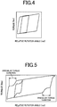
- Fig. 5 shows an operational characteristic of the damper device of a prior art structure. In Fig.
- a relative rotation angle of the damper device is taken along the horizontal axis, while a torque is taken along the vertical axis.
- the gap causes recessed portions (irregular torque variations).
- the hysteresis mechanism of the prior art structure is required to generate the hysteresis torque of an unnecessarily large value.
- the present invention was made in view of the background art described above. It is therefore an object of this invention to provide a hysteresis mechanism of a vehicular damper device of the type which permits generation of different values of a hysteresis torque during operations of the damper device in respective positive and negative directions, which hysteresis mechanism is structured to permit generation of the hysteresis torque of the desired values.
- a hysteresis mechanism for (a) a vehicular damper device including a pair of disc plates functioning as an input rotary member, a hub functioning as an output rotary member, and elastic members interposed between the disc plates and the hub, the hysteresis mechanism being characterized by comprising: (b) a control plate disposed between one of the above-described disc plates and the above-described hub in an axial direction; (c) a first friction member disposed between the above-described control plate and the above-described hub in the axial direction; (d) a second friction member disposed between the above-described hub and the other of the above-described disc plates in the axial direction; and (e) a spring interposed in a preloaded state, and wherein (f) a hysteresis torque generated by a sliding action of the second friction member during a relative rotary motion between the above-described hub and the above-described disc
- the relative rotary motion between the above-described control plate and the above-described hub causes generation of the comparatively large hysteresis torque by the first friction member interposed between the control plate and the hub, while the relative rotary motion between the disc plates and the hub causes generation of the comparatively small hysteresis torque by the second friction member interposed between the disc plates and the hub.
- a rotary motion of the disc plates relative to the above-described control plate and the above-described hub while the control plate and the hub are rotated together causes generation of the comparatively small hysteresis torque by the second friction member interposed between the hub and the other of the disc plates.
- the value of the hysteresis torque generated in the vehicular damper device can be changed depending upon the direction of transmission of the input torque through the damper device (depending upon whether the damper device is operated in the positive direction or negative direction).
- the spring which is interposed between the first control plate and the second control plate is not held in contact with the friction members. Accordingly, unlike the prior art structure, the present structure is not required to dispose the friction members so as to extend through the disc plates, for thereby preventing the rotary motions of the friction members relative to the disc plates, so that the gap is not required to prevent the relative rotary motions, whereby the desired hysteresis torque can be generated.
- the hysteresis mechanism for the vehicular damper device according to the first aspect of the invention is configured such that the above-described first control plate and the above-described second control plate are rotated relative to the above-described hub when the damper device is operated in a positive direction, and are rotated together with the above-described hub when the damper device is operated in a negative direction.
- control plates and the hub are rotated relative to each other while each of the control plates a portion of which is gripped between the disc plates and the elastic members is rotated together with the disc plates during the operation of the vehicular damper device in the positive direction, so that the first friction member interposed between the control plate and the hub generates the comparatively large hysteresis torque, while the second friction member interposed between the hub and the disc plates generates the comparatively small hysteresis torque.
- the hub and the other of the disc plates are rotated relative to each other while the control plate the portion of which is gripped between the hub and the elastic members is rotated together with the hub, so that the second friction member interposed between the hub and the other of the disc plates generates the comparatively small hysteresis torque.
- the value of the hysteresis torque generated in the vehicular damper device can be changed depending upon the direction of transmission of the input torque through the damper device (depending upon whether the damper device is operated in the positive direction or negative direction).
- the hysteresis mechanism for the vehicular damper device according to the first or second aspect of the invention is configured such that the above-described first control plate is axially interposed between the above-described second control plate and the above-indicated one of the above-described disc plates, and a third friction member is axially interposed between the above-indicated one of the disc plates and the above-described first control plate.
- a relative rotary motion between the above-indicated one of the disc plates and the first control plate does not take place during the operation of the vehicular damper device in the positive direction, so that the third friction member does not generate a hysteresis torque.
- Fig. 1 is the front elevational view of a vehicular damper device 10 (hereinafter referred to as a "damper device 10") according to a preferred embodiment of this invention. It is to be understood that the lower half of the damper device 10 with respect to its axis C is not shown in Fig. 1 , and that the view of Fig. 1 is a partly cut away to show an interior structure of disc plates 12 which will be described.
- the damper device 10 includes: the pair of disc plates 12 functioning as an input rotary member and operatively connected to an engine not shown; a hub 14 functioning as an output rotary member and operatively connected to drive wheels; torsion springs 16 functioning as elastic members and operatively interposed between the disc plates 12 and the hub 14; and a hysteresis mechanism 30 described below, which is disposed between the disc plates 12 and the hub 14 and configured to generate a hysteresis torque for thereby damping an input torque variation.
- the pair of disc plates 12 consist of a pair of right and left discs, which are disposed such that the hub 14 and the torsion springs 16 are put therebetween, and which are rotatable about an axis C.
- the disc plates 12 have four spring receptacles 18 formed to accommodate the torsion spring 16 such that the spring receptacles 18 are spaced apart from each other in a circumferential direction of the disc plates 12.
- Each of the disc plates 12 carries a clutch disc 20 fixed to its outer circumferential surface.
- the hub 14 includes a cylindrical portion 14a having a toothed inner circumferential surface for spline-connection to a drive shaft not shown, and flange portions 14b extending radially outwardly from an outer circumferential surface of the cylindrical portion 14a.
- flange portions 14b are formed so as to be equiangularly spaced apart from each other in the circumferential direction.
- the adjacent ones of the hubs 14 define a space for accommodating each torsion spring 16.
- the torsion springs 16 are disposed between the disc plates 12 and the hub 14 through spring seats 22, such that the disc plates 12 and the hub 14 are operatively connected to each other through the torsion springs 16.
- each torsion spring 16 is pressed at one of its opposite ends by the disc plates 12 while the torsion spring 16 presses the hub 14 at the other end.
- the torsion spring 16 is elastically deformed so as to transmit the input torque while absorbing a variation of the input torque.
- the hysteresis mechanism 30 is disposed between the disc plates 12 and the hub 14, radially inwardly of the torsion springs 16, so as to generate different values of the hysteresis torque during operations of the damper device 10 in respective positive and negative directions.
- the structure and operations of the hysteresis mechanism 30 will be described.
- Fig. 2 is the schematic cross sectional view of the damper device 10 taken along line A-A of Fig. 1 . It is noted that Fig. 2 shows the torsion spring 16 by broken lines, and does not show the spring seat 22 and a cushioning member disposed within the torsion spring 16.
- the pair of disc plates 12a and 12b are disposed radially outwardly of the hub 14, so as to hold the torsion springs 16 therebetween.
- the pair of disc plates 12a and 12b are fixed to each other through rivets 24 (shown in Fig. 1 ), and are rotated together.
- the hysteresis mechanism 30 is disposed in parallel with the torsion springs 16.
- the hysteresis mechanism 30 includes: a low-friction plate 32, a first control plate 34, a conical spring 36, a second control plate 38 and a high-friction plate 40, which are axially interposed between the disc plate 12a and the flange portions 14b of the hub 14; and a low-friction plate 42 axially interposed between the flange portions 14b and the disc plate 12b.
- the disc plate 12a is one of the disc plates 12 while the disc plate 12b is the other of the disc plates 12, and the low-friction plate 32, the conical spring 36, the high-friction plate 40 and the low-friction plate 42 respectively function as a third friction member, a spring, a first friction member and a second friction member.
- the low-friction plate 32 consists of a disc which is axially interposed between the disc plate 12a and the first control plate 34.
- frictional forces are generated between mutually abutting surfaces (sliding surfaces) of the disc plate 12a and the low-friction plate 32 and between mutually abutting surfaces (sliding surfaces) of the low-friction plate 32 and the first control plate 34, whereby a comparatively small hysteresis torque H1 is generated.
- the first control plate 34 consists of a disc having abutting portions 34a each in the form of a plate formed in its radially outer portion such that each abutting portion 34a is gripped between one end of the corresponding torsion spring 16 and the disc plate 12b, and between the one end of the corresponding torsion spring 16 and the hub 14 in the circumferential direction of the first control plate 34.
- the abutting portion 34a extends in the axial direction of the disc toward the disc plate 12b so as to be gripped between the torsion spring 16 and the disc plate 12b, and between the one end of the corresponding torsion spring 16 and the hub 14, such that the abutting portion 34a overlaps the hub 14 and the disc plate 12 in the axial direction and such that the abutting portion 34a is formed perpendicularly to the rotating direction of the first control plate 34.
- Each of the abutting portions 34a is held in abutting contact with only one end of the corresponding torsion spring 16, and the abutting portions 34a are provided for the respective torsion springs 16, or for the respective selected ones of the torsion springs 16 the number of which is about a half of the total number of the torsion springs 16, such that the abutting portions 34a are equiangularly spaced apart from each other in the circumferential direction.
- two abutting portions 34a are provided for the four torsion springs 16. It is noted that the abutting portions 34a correspond to a portion of the first control plate.
- the conical spring 36 consists of a coned disc axially interposed between the first control plate 34 and the second control plate 38 such that the conical spring 36 is preloaded therebetween, so that the mutually abutting plates (32 and 34; 38 and 40) are held in pressing contact with each other in the axial direction under a biasing force of the conical spring 36.
- the second control plate 38 consists of a disc having abutting portions 38a each in the form of a plate formed in its radially outer portion such that each abutting portion 38a is gripped between one end of the corresponding torsion spring 16 and the disc plate 12b, and between the one end of the corresponding torsion spring 16 and the hub 14 in the circumferential direction of the second control plate 38.
- the abutting portion 38a extends in the axial direction of the disc toward the disc plate 12b so as to be gripped between the torsion spring 16 and the disc plate 12b, and between the torsion spring 16 and the hub 14, such that the abutting portion 38a overlaps the hub 14 and the disc plate 12b in the axial direction and such that the abutting portion 38a is formed perpendicularly to the rotating direction of the second control plate 38.
- Each of the abutting portions 38a is held in abutting contact with only one end of the corresponding torsion spring 16, which is the same one end of the corresponding torsion spring with which each of the abutting portions 34a is held in abutting contact, and the abutting portions 38a are provided for the respective torsion springs 16, or for the respective selected ones of the torsion springs 16 the number of which is about a half of the total number of the torsion springs 16, such that the abutting portions 38a are equiangularly spaced apart from each other in the circumferential direction.
- two abutting portions 38a are provided for the four torsion springs 16.
- each of the abutting portions 38a is gripped between the abutting portion 34a and the hub 14, and between the abutting portion 34a and the disc plate 12b in the circumferential direction. That is, the abutting portion 34a and the abutting portion 38a are superposed on each other between the torsion spring 16 and the disc plate 12b, and between the torsion spring 16 and the hub 14. It is noted that the abutting portions 38a correspond to a portion of the second control plate.
- the high-friction plate 40 consists of a disc which is axially interposed between the second control plate 38 and the flange portions 14b of the hub 14. During a relative rotary motion between the second control plate 38 and the hub 14, a frictional force is generated between mutually abutting surfaces (sliding surfaces) of the second control plate 38 and the high-friction plate 40, whereby a comparatively large hysteresis torque H2 larger than the comparatively small hysteresis torque H1 is generated.
- the low-friction plate 42 consists of a disc which is axially interposed between the flange portions 14b of the hub 14 and the disc plate 12b. During a relative rotary motion between the hub 14 and the disc plate 12b, a frictional force is generated between mutually abutting surfaces (sliding surfaces) of the low-friction plate 42 and the disc plate 12b, whereby the comparatively small hysteresis torque H1 is generated.
- Figs. 3 are the schematic views for explaining the operation of the damper device 10. It is noted that the damper device 10 is rotated about the axis C in the counterclockwise direction.
- thick solid lines indicate the disc plates 12 wherein the four spring receptacles 18 are formed so as to be spaced apart from each other in the circumferential direction of the disc plates 12.
- Broken hatching lines indicate the hub 14 having the four flange portions 14b which are equiangularly spaced apart from each other in the circumferential direction.
- the four torsion springs 16 which are indicated by saw-toothed lines are accommodated in the respective spring receptacles 18.
- Solid black areas indicate the abutting portion 34a of the first control plate 34 and the abutting portion 38a of the second control plate 38, which are superposed on each other in the circumferential direction between the torsion springs 16 and the hub 14, and between the torsion springs 16 and the disc plates 12.
- Each of the abutting portions 34a, 38a is formed at two circumferentially spaced-apart positions, that is, for every two torsion springs out of the four torsion springs 16.
- Each of the two abutting portions 34, 38 is disposed in abutting contact with one end of the corresponding torsion spring 16 at which the torsion spring 16 receives (i.e. is subjected to) a torque which is input (transmitted) to the damper device 10 through the disc plates.
- Fig. 3(a) indicates an operating state of the damper device 10 in which an input torque is not transmitted to the damper device 10, that is, a relatively rotated state does not take place in the damper device 10
- Fig. 3(b) indicates an operating state in which the damper device 10 is operated in the positive direction
- Fig. 3(b) indicates an operating state in which the damper device 10 is operated in the negative direction.
- the torsion springs 16 are not compressed, as shown in Fig. 3(a) , so that the disc plates and the flange portions 14b of the hub 14 substantially overlap each other.
- the disc plates 12 are rotated about the axis C relative to the hub 14 in the direction toward the viewer of the figure, so that the control plates 34 and 38 held in abutting contact with the disc plate 12b are also rotated together with the disc plate 12 about the axis C relative to the hub 14 in the direction toward the viewer of the figure.
- This relative rotary motion between the hub 14 and the control plates 34, 38 causes each of the second control plate 38 and the flange portions 14b of the hub 14 to slide on the respective sliding surfaces (abutting surfaces) of the high-friction plate 40 interposed between the second control plate 38 and the flange portions 14b of the hub 14, whereby the high-friction plate 40 transmits the comparatively large hysteresis torque H2 to the hub 14.
- the relative rotary motion between the disc plate 12b and the hub 14 causes the disc plate 12b to slide on the sliding surface (abutting surface) of the low-friction plate 42 interposed between the disc plate 12b and the flange portions 14b, whereby the low-friction plate 42 transmits the comparatively small hysteresis torque H1 to the hub 14.
- the disc plate 12a and the first control plate 34 are rotated together, without a relative rotary motion therebetween, so that the low-friction plate 32 interposed therebetwen does not transmit the small hysteresis torque H1 to the hub 14.
- the large hysteresis torque H2 and the small hysteresis torque H1 are generated during the operation of the damper device 10 in the positive direction.
- the hub 14 is rotated about the axis C relative to the disc plates 12 in the direction toward the viewer of the figure, so that the control plates 34 and 38 held in abutting contact with the hub 14 are also rotated together with the hub 14 about the axis C relative to the disc plates 12 in the direction toward the viewer of the figure.
- the relative rotary motion between the disc plate 12a and the first control plate 34 causes the control plate 34 to slide on the sliding surface (abutting surface) of the low-friction plate 32 interposed between the disc plate 12a and the first control plate 34, whereby the low-friction plate 32 transmits the comparatively small hysteresis torque H1 to the disc plate 12a.
- the second control plate 38 and the hub 14 are rotated together, without a relative rotary motion therebetween, so that the high-friction plate 40 interposed therebetwen does not transmit the large hysteresis torque H2 to the disc plates 12.
- the small hysteresis torque H1 is generated by the low-friction plates 32 and 42 during the operation of the damper device 10 in the negative direction.
- control plates 34 and 38 are rotated relative to the hub 14 during the operation of the damper device 10 in the positive direction, while the control plates 34 and 38 are rotated together with the hub during the operation of the damper device 10 in the negative direction. Accordingly, the friction plates to be effectively operated are switched depending upon whether the damper device 10 is operated in the positive direction or in the negative direction, so that the hysteresis torque to be generated changes depending upon whether the damper device 10 is operated in the positive or negative direction.
- the hysteresis mechanism 30 uses the two control plates in the form of the first control plate 34 and the second control plate 38, which are axially movable relative to each other, and between which the conical spring 36 is interposed.
- the provision of the two control plates between which the conical spring 36 is interposed eliminates direct contacts of the conical spring 36 with the friction members, and a need to prevent rotary motions of the friction members relative to the disc plates to prevent wearing of the friction members due to their sliding contacts with the conical spring 36.
- the present hysteresis mechanism 30 is not required to prevent the rotary motions of the friction members relative to the disc plates, so that the hysteresis mechanism 30 does not suffer from the irregular torque variations due to a gap required to prevent the relative rotary motions.
- Fig. 4 showing the operational characteristic of the damper device 10
- no irregular torque variations encountered in the prior art structure take place in the present damper device 10, in the absence of the gap required to prevent the above-indicated relative rotary motions, as described above.
- the present embodiment is configured such that when the damper device 10 is operated in the positive direction, the relative rotary motion between the control plates 34 and 38 and the hub 14 causes generation of the comparatively large hysteresis torque H2 by the high-friction plate 40 interposed between the second control plate 38 and the hub 14, while the relative rotary motion between the disc plate 12 and the hub 14 causes generation of the comparatively small hysteresis torque H1 by the low-friction plate 42 interposed between the disc plate 12 and the hub 14.
- the present structure is not required to dispose the friction members so as to extend through the disc plates, for thereby preventing the rotary motions of the friction members relative to the spring, so that a gap is not required to prevent the relative rotary motions, whereby the desired hysteresis torque can be generated.
- the input torque is transmitted to the damper device 10 through the input rotary member in the form of the disc plates 12, when the damper device 10 is operated in the positive direction.
- the control plates 34 and 38 of the hysteresis mechanism 30 are rotated together with the disc plates 12.
- the input torque is transmitted to the damper device 10 through the output rotary member in the form of the hub 14, when the damper device 10 is operated in the negative direction.
- the control plates 34 and 38 of the hysteresis mechanism 30 are rotated together with the hub 14.
- the present embodiment is further configured such that the each of the abutting portions 34a and 38a of the control plates 34 and 38 which are gripped between the disc plates 12 and the torsion springs 16 is rotated together with the disc plates 12 when the damper device 10 is operated in the positive direction. Accordingly, the control plates 34 and 38 and the hub 14 are rotated relative to each other, so that the high-friction plate 40 interposed between the second control plate 38 and the hub 14 generates the comparatively large hysteresis torque H2, while the low-friction plate 42 interposed between the hub 14 and the disc plate 12b generates the comparatively small hysteresis torque H1.
- each of the control plates 34 and 38 the portion of which is gripped between the hub 14 and the torsion spring 16 is rotated together with the hub 14, so that the hub 14 and the disc plate 12b are rotated relative to each other, whereby the low-friction plate 42 interposed between the hub 14 and the disc plate 12b generates the comparatively small hysteresis torque H1.
- the value of the hysteresis torque generated in the damper device 10 can be changed depending upon the direction of transmission of the input torque through the damper device 10 (depending upon whether the damper device is operated in the positive direction or negative direction).
- the present embodiment is also configured such that a relative rotary motion between the disc plate 12a and the first control plate 34 does not take place during the operation of the damper device 10 in the positive direction, so that the low-friction plate 32 does not generate a hysteresis torque.
- a relative rotary motion takes place between the disc plate 12a and the first control plate 34, so that the low-friction plate 32 interposed therebetween generates the comparatively small hysteresis torque H1.
- the hysteresis torque H1 generated by the low-friction plate 32 and the hysteresis torque H1 generated by the low-friction plate 42 are equal to each other.
- these hysteresis torque values H1 and H2 need not be equal to each other and may be different from each other.
- each of the first and second control plates 34 and 38 has the two abutting portions 34a, 38a for the four torsion springs 16, such that the two abutting portions 34a, 38a are equiangularly spaced apart from each other in the circumferential direction of the control plates 34, 38.
- the number of the abutting portions 34a, 38a may be equal to the number of the torsion springs 16 (four torsion springs 16 in the illustrated embodiment).
- the number of the torsion springs 16 may be suitably selected (for example, three torsion springs 16 may be provided).
- the number of the abutting portions 34a, 38a may be suitably selected depending upon the number of the torsion springs 16.
Landscapes
- Engineering & Computer Science (AREA)
- General Engineering & Computer Science (AREA)
- Physics & Mathematics (AREA)
- Acoustics & Sound (AREA)
- Aviation & Aerospace Engineering (AREA)
- Mechanical Engineering (AREA)
- Mechanical Operated Clutches (AREA)
Abstract
Description
- The present invention relates to a hysteresis mechanism provided in a vehicular damper device, and more particularly to a structure of the hysteresis mechanism which permits a change of a hysteresis torque value depending upon a direction of transmission of a torque through the damper device.
- In a power transmitting system disposed between an engine and drive wheels of a vehicle, there is provided a damper device for absorbing an input torque variation. There is known the damper device of a type provided with a hysteresis mechanism configured to generate a hysteresis torque due to friction during relative rotation between disc plates and a hub of the damper device, for thereby damping the torque variation.
- Patent Document 1 discloses an example of a damper device (damper disc device) wherein a conical spring 9 is disposed between a clutch plate 4 and a
first friction plate 10, and thefirst friction plate 10 extends through the clutch plate 4, for preventing a rotary motion of the conical spring 9 relative to the clutch plate 4 and thefirst friction plate 10. During a rotary motion of an input rotary member of the damper device in a positive direction, fourfriction washers friction washers 11 and 16, that is, the first friction washer 11 and thefourth friction washer 16 generate a comparatively small hysteresis torque H2 due to their sliding friction, relative to the rotary motion in the positive direction. Thus, the damper device is structured such that the hysteresis torque to be generated changes depending upon whether the damper device is operated in the positive or negative direction. -
- Patent Document 1:
-
JP-5-45259 U - Patent Document 2:
-
JP-2010-230098 A1 - Patent Document 3:
-
JP-2007-218347 A1 - Patent Document 4:
-
JP-7-259879 A1 - By the way, the damper device (damper disc device) disclosed in Patent Document 1 is configured such that a portion of the
first friction plate 10 extends through the clutch plate 4, to prevent a rotary motion of thefirst friction plate 10, as shown inFig. 2 of the document, and such that a gap is left between the above-indicated extending portion of thefirst friction plate 10 and the clutch plate 4 so that thefirst friction plate 10 is axially movable. This gap gives rise to a risk of failure to generate a desired value of hysteresis torque during a relative rotary motion between the clutch plate 4 and flange portions 2.Fig. 5 shows an operational characteristic of the damper device of a prior art structure. InFig. 5 , a relative rotation angle of the damper device is taken along the horizontal axis, while a torque is taken along the vertical axis. As shown inFig. 5 , the gap causes recessed portions (irregular torque variations). In view of the irregular torque variations, the hysteresis mechanism of the prior art structure is required to generate the hysteresis torque of an unnecessarily large value. - The present invention was made in view of the background art described above. It is therefore an object of this invention to provide a hysteresis mechanism of a vehicular damper device of the type which permits generation of different values of a hysteresis torque during operations of the damper device in respective positive and negative directions, which hysteresis mechanism is structured to permit generation of the hysteresis torque of the desired values.
- The object described above is achieved according to a first aspect of the invention, which provides a hysteresis mechanism for (a) a vehicular damper device including a pair of disc plates functioning as an input rotary member, a hub functioning as an output rotary member, and elastic members interposed between the disc plates and the hub, the hysteresis mechanism being characterized by comprising: (b) a control plate disposed between one of the above-described disc plates and the above-described hub in an axial direction; (c) a first friction member disposed between the above-described control plate and the above-described hub in the axial direction; (d) a second friction member disposed between the above-described hub and the other of the above-described disc plates in the axial direction; and (e) a spring interposed in a preloaded state, and wherein (f) a hysteresis torque generated by a sliding action of the second friction member during a relative rotary motion between the above-described hub and the above-described disc plates is smaller than a hysteresis torque generated by a sliding action of the above-described first friction member during a relative rotary motion between the other of the above-described control plates and the above-described hub; and (g) the above-described control plate comprises a first control plate and a second control plate, and the above-described spring is interposed between the above-described first control plate and the above-described second control plate in the axial direction, each of the above-described first control plate and the above-described second control plate having a portion which is gripped between one end of the above-described elastic members and the above-described hub, and between the one end of the above-described elastic members and the above-described disc plates in a circumferential direction. Advantageous Effects of The Invention
- In the vehicular damper device constructed as described above, the relative rotary motion between the above-described control plate and the above-described hub causes generation of the comparatively large hysteresis torque by the first friction member interposed between the control plate and the hub, while the relative rotary motion between the disc plates and the hub causes generation of the comparatively small hysteresis torque by the second friction member interposed between the disc plates and the hub. On the other hand, a rotary motion of the disc plates relative to the above-described control plate and the above-described hub while the control plate and the hub are rotated together causes generation of the comparatively small hysteresis torque by the second friction member interposed between the hub and the other of the disc plates. Thus, the value of the hysteresis torque generated in the vehicular damper device can be changed depending upon the direction of transmission of the input torque through the damper device (depending upon whether the damper device is operated in the positive direction or negative direction). It is noted that the spring which is interposed between the first control plate and the second control plate is not held in contact with the friction members. Accordingly, unlike the prior art structure, the present structure is not required to dispose the friction members so as to extend through the disc plates, for thereby preventing the rotary motions of the friction members relative to the disc plates, so that the gap is not required to prevent the relative rotary motions, whereby the desired hysteresis torque can be generated.
- According to a second aspect of the invention, the hysteresis mechanism for the vehicular damper device according to the first aspect of the invention is configured such that the above-described first control plate and the above-described second control plate are rotated relative to the above-described hub when the damper device is operated in a positive direction, and are rotated together with the above-described hub when the damper device is operated in a negative direction. According to this second aspect of the invention, the control plates and the hub are rotated relative to each other while each of the control plates a portion of which is gripped between the disc plates and the elastic members is rotated together with the disc plates during the operation of the vehicular damper device in the positive direction, so that the first friction member interposed between the control plate and the hub generates the comparatively large hysteresis torque, while the second friction member interposed between the hub and the disc plates generates the comparatively small hysteresis torque. When the vehicular damper device is operated in the negative direction, on the other hand, the hub and the other of the disc plates are rotated relative to each other while the control plate the portion of which is gripped between the hub and the elastic members is rotated together with the hub, so that the second friction member interposed between the hub and the other of the disc plates generates the comparatively small hysteresis torque. Thus, the value of the hysteresis torque generated in the vehicular damper device can be changed depending upon the direction of transmission of the input torque through the damper device (depending upon whether the damper device is operated in the positive direction or negative direction).
- According to a third aspect of the invention, the hysteresis mechanism for the vehicular damper device according to the first or second aspect of the invention is configured such that the above-described first control plate is axially interposed between the above-described second control plate and the above-indicated one of the above-described disc plates, and a third friction member is axially interposed between the above-indicated one of the disc plates and the above-described first control plate. According to this third aspect of the invention, a relative rotary motion between the above-indicated one of the disc plates and the first control plate does not take place during the operation of the vehicular damper device in the positive direction, so that the third friction member does not generate a hysteresis torque. During the operation of the vehicular damper device in the negative direction, however, a relative rotary motion takes place between the above-indicated one of the disc plates and the first control plate, so that the third friction member interposed therebetween generates the comparatively small hysteresis torque.
-
-
Fig. 1 is a front elevational view of a vehicular damper device according to a preferred embodiment of this invention; -
Fig. 2 is a schematic cross sectional view of the vehicular damper device ofFig. 1 taken along line A-A; -
Figs. 3 are schematic views for explaining an operation of the vehicular damper device ofFig. 1 ; -
Fig. 4 is a view showing an operational characteristic of the vehicular damper device ofFig. 1 ; and -
Fig. 5 is a view showing an operational characteristic of a vehicular damper device of a prior art structure. - An embodiment of the invention will be described in detail by reference to the drawings. It is to be understood that the drawings are simplified or transformed as needed, and do not necessarily accurately represent the dimensions and shapes of individual portions of the embodiment.
-
Fig. 1 is the front elevational view of a vehicular damper device 10 (hereinafter referred to as a "damper device 10") according to a preferred embodiment of this invention. It is to be understood that the lower half of thedamper device 10 with respect to its axis C is not shown inFig. 1 , and that the view ofFig. 1 is a partly cut away to show an interior structure ofdisc plates 12 which will be described. - The
damper device 10 includes: the pair ofdisc plates 12 functioning as an input rotary member and operatively connected to an engine not shown; ahub 14 functioning as an output rotary member and operatively connected to drive wheels;torsion springs 16 functioning as elastic members and operatively interposed between thedisc plates 12 and thehub 14; and ahysteresis mechanism 30 described below, which is disposed between thedisc plates 12 and thehub 14 and configured to generate a hysteresis torque for thereby damping an input torque variation. - The pair of
disc plates 12 consist of a pair of right and left discs, which are disposed such that thehub 14 and thetorsion springs 16 are put therebetween, and which are rotatable about an axis C. Thedisc plates 12 have fourspring receptacles 18 formed to accommodate thetorsion spring 16 such that thespring receptacles 18 are spaced apart from each other in a circumferential direction of thedisc plates 12. Each of thedisc plates 12 carries aclutch disc 20 fixed to its outer circumferential surface. - The
hub 14 includes acylindrical portion 14a having a toothed inner circumferential surface for spline-connection to a drive shaft not shown, andflange portions 14b extending radially outwardly from an outer circumferential surface of thecylindrical portion 14a. In the present embodiment, fourflange portions 14b are formed so as to be equiangularly spaced apart from each other in the circumferential direction. The adjacent ones of thehubs 14 define a space for accommodating eachtorsion spring 16. - The
torsion springs 16 are disposed between thedisc plates 12 and thehub 14 throughspring seats 22, such that thedisc plates 12 and thehub 14 are operatively connected to each other through thetorsion springs 16. When a torque is transmitted from thedisc plates 12 to thehub 14, for example, eachtorsion spring 16 is pressed at one of its opposite ends by thedisc plates 12 while thetorsion spring 16 presses thehub 14 at the other end. At this time, thetorsion spring 16 is elastically deformed so as to transmit the input torque while absorbing a variation of the input torque. - The
hysteresis mechanism 30 is disposed between thedisc plates 12 and thehub 14, radially inwardly of thetorsion springs 16, so as to generate different values of the hysteresis torque during operations of thedamper device 10 in respective positive and negative directions. The structure and operations of thehysteresis mechanism 30 will be described. -
Fig. 2 is the schematic cross sectional view of thedamper device 10 taken along line A-A ofFig. 1 . It is noted thatFig. 2 shows thetorsion spring 16 by broken lines, and does not show thespring seat 22 and a cushioning member disposed within thetorsion spring 16. - As also shown in
Fig. 2 , the pair ofdisc plates hub 14, so as to hold the torsion springs 16 therebetween. In this respect, it is noted that the pair ofdisc plates Fig. 1 ), and are rotated together. Between thedisc plates hub 14, thehysteresis mechanism 30 is disposed in parallel with the torsion springs 16. - The
hysteresis mechanism 30 includes: a low-friction plate 32, afirst control plate 34, aconical spring 36, asecond control plate 38 and a high-friction plate 40, which are axially interposed between thedisc plate 12a and theflange portions 14b of thehub 14; and a low-friction plate 42 axially interposed between theflange portions 14b and thedisc plate 12b. In the present embodiment, thedisc plate 12a is one of thedisc plates 12 while thedisc plate 12b is the other of thedisc plates 12, and the low-friction plate 32, theconical spring 36, the high-friction plate 40 and the low-friction plate 42 respectively function as a third friction member, a spring, a first friction member and a second friction member. - The low-
friction plate 32 consists of a disc which is axially interposed between thedisc plate 12a and thefirst control plate 34. During a relative rotary motion between thedisc plate 12a and thefirst control plate 34, frictional forces are generated between mutually abutting surfaces (sliding surfaces) of thedisc plate 12a and the low-friction plate 32 and between mutually abutting surfaces (sliding surfaces) of the low-friction plate 32 and thefirst control plate 34, whereby a comparatively small hysteresis torque H1 is generated. - The
first control plate 34 consists of a disc having abuttingportions 34a each in the form of a plate formed in its radially outer portion such that each abuttingportion 34a is gripped between one end of thecorresponding torsion spring 16 and thedisc plate 12b, and between the one end of thecorresponding torsion spring 16 and thehub 14 in the circumferential direction of thefirst control plate 34. The abuttingportion 34a extends in the axial direction of the disc toward thedisc plate 12b so as to be gripped between thetorsion spring 16 and thedisc plate 12b, and between the one end of thecorresponding torsion spring 16 and thehub 14, such that the abuttingportion 34a overlaps thehub 14 and thedisc plate 12 in the axial direction and such that the abuttingportion 34a is formed perpendicularly to the rotating direction of thefirst control plate 34. Each of the abuttingportions 34a is held in abutting contact with only one end of thecorresponding torsion spring 16, and the abuttingportions 34a are provided for the respective torsion springs 16, or for the respective selected ones of the torsion springs 16 the number of which is about a half of the total number of the torsion springs 16, such that the abuttingportions 34a are equiangularly spaced apart from each other in the circumferential direction. In the present embodiment, two abuttingportions 34a are provided for the four torsion springs 16. It is noted that the abuttingportions 34a correspond to a portion of the first control plate. - The
conical spring 36 consists of a coned disc axially interposed between thefirst control plate 34 and thesecond control plate 38 such that theconical spring 36 is preloaded therebetween, so that the mutually abutting plates (32 and 34; 38 and 40) are held in pressing contact with each other in the axial direction under a biasing force of theconical spring 36. - The
second control plate 38 consists of a disc having abuttingportions 38a each in the form of a plate formed in its radially outer portion such that each abuttingportion 38a is gripped between one end of thecorresponding torsion spring 16 and thedisc plate 12b, and between the one end of thecorresponding torsion spring 16 and thehub 14 in the circumferential direction of thesecond control plate 38. Like the abuttingportion 34a, the abuttingportion 38a extends in the axial direction of the disc toward thedisc plate 12b so as to be gripped between thetorsion spring 16 and thedisc plate 12b, and between thetorsion spring 16 and thehub 14, such that the abuttingportion 38a overlaps thehub 14 and thedisc plate 12b in the axial direction and such that the abuttingportion 38a is formed perpendicularly to the rotating direction of thesecond control plate 38. Each of the abuttingportions 38a is held in abutting contact with only one end of thecorresponding torsion spring 16, which is the same one end of the corresponding torsion spring with which each of the abuttingportions 34a is held in abutting contact, and the abuttingportions 38a are provided for the respective torsion springs 16, or for the respective selected ones of the torsion springs 16 the number of which is about a half of the total number of the torsion springs 16, such that the abuttingportions 38a are equiangularly spaced apart from each other in the circumferential direction. In the present embodiment, two abuttingportions 38a are provided for the four torsion springs 16.Fig. 2 illustrates that each of the abuttingportions 38a is gripped between the abuttingportion 34a and thehub 14, and between the abuttingportion 34a and thedisc plate 12b in the circumferential direction. That is, the abuttingportion 34a and the abuttingportion 38a are superposed on each other between thetorsion spring 16 and thedisc plate 12b, and between thetorsion spring 16 and thehub 14. It is noted that the abuttingportions 38a correspond to a portion of the second control plate. - The high-
friction plate 40 consists of a disc which is axially interposed between thesecond control plate 38 and theflange portions 14b of thehub 14. During a relative rotary motion between thesecond control plate 38 and thehub 14, a frictional force is generated between mutually abutting surfaces (sliding surfaces) of thesecond control plate 38 and the high-friction plate 40, whereby a comparatively large hysteresis torque H2 larger than the comparatively small hysteresis torque H1 is generated. - The low-
friction plate 42 consists of a disc which is axially interposed between theflange portions 14b of thehub 14 and thedisc plate 12b. During a relative rotary motion between thehub 14 and thedisc plate 12b, a frictional force is generated between mutually abutting surfaces (sliding surfaces) of the low-friction plate 42 and thedisc plate 12b, whereby the comparatively small hysteresis torque H1 is generated. - The operation of the
hysteresis mechanism 30 structured as described above will be described.Figs. 3 are the schematic views for explaining the operation of thedamper device 10. It is noted that thedamper device 10 is rotated about the axis C in the counterclockwise direction. InFigs. 3 , thick solid lines indicate thedisc plates 12 wherein the fourspring receptacles 18 are formed so as to be spaced apart from each other in the circumferential direction of thedisc plates 12. Broken hatching lines indicate thehub 14 having the fourflange portions 14b which are equiangularly spaced apart from each other in the circumferential direction. The four torsion springs 16 which are indicated by saw-toothed lines are accommodated in therespective spring receptacles 18. Solid black areas indicate the abuttingportion 34a of thefirst control plate 34 and the abuttingportion 38a of thesecond control plate 38, which are superposed on each other in the circumferential direction between the torsion springs 16 and thehub 14, and between the torsion springs 16 and thedisc plates 12. Each of the abuttingportions portions corresponding torsion spring 16 at which thetorsion spring 16 receives (i.e. is subjected to) a torque which is input (transmitted) to thedamper device 10 through the disc plates. -
Fig. 3(a) indicates an operating state of thedamper device 10 in which an input torque is not transmitted to thedamper device 10, that is, a relatively rotated state does not take place in thedamper device 10, andFig. 3(b) indicates an operating state in which thedamper device 10 is operated in the positive direction, whileFig. 3(b) indicates an operating state in which thedamper device 10 is operated in the negative direction. In the operating state in which the input torque is not transmitted to thedamper device 10, the torsion springs 16 are not compressed, as shown inFig. 3(a) , so that the disc plates and theflange portions 14b of thehub 14 substantially overlap each other. - When the
damper device 10 is operated in the positive direction, the input torque is transmitted to thedamper device 10 through thedisc plates 12, so that thedisc plates 12 are rotated in the counterclockwise direction relative to thehub 14, as shown inFig. 3(b) . As a result, thedisc plates 12 force thefirst control plate 34 and the second control plate 38 (hereinafter referred to as "control plates control plates 34 and 38 (in the counterclockwise direction), such that thecontrol plates disc plates 12. In thedamper device 10 as shown inFig. 2 , thedisc plates 12 are rotated about the axis C relative to thehub 14 in the direction toward the viewer of the figure, so that thecontrol plates disc plate 12b are also rotated together with thedisc plate 12 about the axis C relative to thehub 14 in the direction toward the viewer of the figure. This relative rotary motion between thehub 14 and thecontrol plates second control plate 38 and theflange portions 14b of thehub 14 to slide on the respective sliding surfaces (abutting surfaces) of the high-friction plate 40 interposed between thesecond control plate 38 and theflange portions 14b of thehub 14, whereby the high-friction plate 40 transmits the comparatively large hysteresis torque H2 to thehub 14. Further, the relative rotary motion between thedisc plate 12b and thehub 14 causes thedisc plate 12b to slide on the sliding surface (abutting surface) of the low-friction plate 42 interposed between thedisc plate 12b and theflange portions 14b, whereby the low-friction plate 42 transmits the comparatively small hysteresis torque H1 to thehub 14. On the other hand, thedisc plate 12a and thefirst control plate 34 are rotated together, without a relative rotary motion therebetween, so that the low-friction plate 32 interposed therebetwen does not transmit the small hysteresis torque H1 to thehub 14. Thus, the large hysteresis torque H2 and the small hysteresis torque H1 are generated during the operation of thedamper device 10 in the positive direction. - There will next be described the operation of the
damper device 10 in the negative direction, in which the input torque is transmitted to thedamper device 10 through thehub 14. In the operation of thedamper device 10 in the negative direction, the input torque is transmitted to thedamper device 10 through thehub 14, so that thehub 14 is rotated in the counterclockwise direction relative to thedisc plates 12, as shown inFig. 3(c) . As a result, thehub 14 forces thecontrol plates control plates hub 14. In thedamper device 10 as shown inFig. 2 , thehub 14 is rotated about the axis C relative to thedisc plates 12 in the direction toward the viewer of the figure, so that thecontrol plates hub 14 are also rotated together with thehub 14 about the axis C relative to thedisc plates 12 in the direction toward the viewer of the figure. This relative rotary motion between thehub 14 and thedisc plates 12 and between thecontrol plates disc plates 12 causes each of theflange portions 14b and thedisc plate 12b to slide on the respective sliding surfaces (abutting surfaces) of the low-friction plate 42 interposed between theflange portions 14b and thedisc plate 12b, whereby the low-friction plate 42 transmits the comparatively small hysteresis torque H1 to thehub 14. Further, the relative rotary motion between thedisc plate 12a and thefirst control plate 34 causes thecontrol plate 34 to slide on the sliding surface (abutting surface) of the low-friction plate 32 interposed between thedisc plate 12a and thefirst control plate 34, whereby the low-friction plate 32 transmits the comparatively small hysteresis torque H1 to thedisc plate 12a. On the other hand, thesecond control plate 38 and thehub 14 are rotated together, without a relative rotary motion therebetween, so that the high-friction plate 40 interposed therebetwen does not transmit the large hysteresis torque H2 to thedisc plates 12. Thus, the small hysteresis torque H1 is generated by the low-friction plates damper device 10 in the negative direction. - As described above, the
control plates hub 14 during the operation of thedamper device 10 in the positive direction, while thecontrol plates damper device 10 in the negative direction. Accordingly, the friction plates to be effectively operated are switched depending upon whether thedamper device 10 is operated in the positive direction or in the negative direction, so that the hysteresis torque to be generated changes depending upon whether thedamper device 10 is operated in the positive or negative direction. - The
hysteresis mechanism 30 according to the present embodiment uses the two control plates in the form of thefirst control plate 34 and thesecond control plate 38, which are axially movable relative to each other, and between which theconical spring 36 is interposed. The provision of the two control plates between which theconical spring 36 is interposed eliminates direct contacts of theconical spring 36 with the friction members, and a need to prevent rotary motions of the friction members relative to the disc plates to prevent wearing of the friction members due to their sliding contacts with theconical spring 36. Thus, unlike the hysteresis mechanism of the prior art structure, thepresent hysteresis mechanism 30 is not required to prevent the rotary motions of the friction members relative to the disc plates, so that thehysteresis mechanism 30 does not suffer from the irregular torque variations due to a gap required to prevent the relative rotary motions. As shown inFig. 4 showing the operational characteristic of thedamper device 10, no irregular torque variations encountered in the prior art structure take place in thepresent damper device 10, in the absence of the gap required to prevent the above-indicated relative rotary motions, as described above. - As described above, the present embodiment is configured such that when the
damper device 10 is operated in the positive direction, the relative rotary motion between thecontrol plates hub 14 causes generation of the comparatively large hysteresis torque H2 by the high-friction plate 40 interposed between thesecond control plate 38 and thehub 14, while the relative rotary motion between thedisc plate 12 and thehub 14 causes generation of the comparatively small hysteresis torque H1 by the low-friction plate 42 interposed between thedisc plate 12 and thehub 14. On the other hand, when thedamper device 10 is operated in the negative direction, a rotary motion of thedisc plates 12 relative to thecontrol plates hub 14 while thecontrol plates hub 14 are rotated together causes generation of the comparatively small hysteresis torque H1 by the low-friction plate 42 interposed between thehub 14 and thedisc plate 12b. Thus, the value of the hysteresis torque generated in thedamper device 10 can be changed depending upon the direction of transmission of the input torque through the damper device 10 (depending upon whether thedamper device 10 is operated in the positive direction or negative direction). It is noted that theconical spring 36 which is interposed between thefirst control plate 34 and thesecond control plate 38 is not held in contact with the friction members. Accordingly, unlike the prior art structure, the present structure is not required to dispose the friction members so as to extend through the disc plates, for thereby preventing the rotary motions of the friction members relative to the spring, so that a gap is not required to prevent the relative rotary motions, whereby the desired hysteresis torque can be generated. - In the present embodiment, the input torque is transmitted to the
damper device 10 through the input rotary member in the form of thedisc plates 12, when thedamper device 10 is operated in the positive direction. In this case, thecontrol plates hysteresis mechanism 30 are rotated together with thedisc plates 12. Further, the input torque is transmitted to thedamper device 10 through the output rotary member in the form of thehub 14, when thedamper device 10 is operated in the negative direction. In this case, thecontrol plates hysteresis mechanism 30 are rotated together with thehub 14. - The present embodiment is further configured such that the each of the abutting
portions control plates disc plates 12 and the torsion springs 16 is rotated together with thedisc plates 12 when thedamper device 10 is operated in the positive direction. Accordingly, thecontrol plates hub 14 are rotated relative to each other, so that the high-friction plate 40 interposed between thesecond control plate 38 and thehub 14 generates the comparatively large hysteresis torque H2, while the low-friction plate 42 interposed between thehub 14 and thedisc plate 12b generates the comparatively small hysteresis torque H1. When thedamper device 10 is operated in the negative direction, on the other hand, each of thecontrol plates hub 14 and thetorsion spring 16 is rotated together with thehub 14, so that thehub 14 and thedisc plate 12b are rotated relative to each other, whereby the low-friction plate 42 interposed between thehub 14 and thedisc plate 12b generates the comparatively small hysteresis torque H1. Thus, the value of the hysteresis torque generated in thedamper device 10 can be changed depending upon the direction of transmission of the input torque through the damper device 10 (depending upon whether the damper device is operated in the positive direction or negative direction). - The present embodiment is also configured such that a relative rotary motion between the
disc plate 12a and thefirst control plate 34 does not take place during the operation of thedamper device 10 in the positive direction, so that the low-friction plate 32 does not generate a hysteresis torque. During the operation of thedamper device 10 in the negative direction, however, a relative rotary motion takes place between thedisc plate 12a and thefirst control plate 34, so that the low-friction plate 32 interposed therebetween generates the comparatively small hysteresis torque H1. - While the embodiment of this invention has been described in detail by reference to the drawings, it is to be understood that the invention may be otherwise embodied.
- In the illustrated embodiment, the hysteresis torque H1 generated by the low-
friction plate 32 and the hysteresis torque H1 generated by the low-friction plate 42 are equal to each other. However, these hysteresis torque values H1 and H2 need not be equal to each other and may be different from each other. - In the illustrated embodiment, each of the first and
second control plates portions portions control plates portions - Although the four torsion springs 16 are provided in the illustrated embodiment, the number of the torsion springs 16 may be suitably selected (for example, three torsion springs 16 may be provided). The number of the abutting
portions - While the embodiment of the invention has been described for illustrative purpose only, it is to be understood that the invention may be embodied with various changes and improvements which may occur to those skilled in the art.
-
- 10:
- Damper device
- 12:
- A pair of disc plates
- 12a:
- One of the pair of disc plates
- 12b:
- The other of the pair of disc plates
- 14:
- Hub
- 16:
- Torsion springs (Elastic members)
- 30:
- Hysteresis mechanism
- 32:
- Low-friction plate (Third friction member)
- 34:
- First control plate
- 34a:
- Abutting portions (Portion of the first control plate)
- 36:
- Conical spring (Spring)
- 38:
- Second control plate
- 38a:
- Abutting portions (Portion of the second control plate)
- 40:
- High-friction plate (First friction member)
- 42:
- Low-friction plate (Second friction member)
- H1, H2:
- Hysteresis torques
Claims (3)
- A hysteresis mechanism for a vehicular damper device including a pair of disc plates functioning as an input rotary member, a hub functioning as an output rotary member, and elastic members interposed between the disc plates and the hub, said hysteresis mechanism being characterized by comprising:a control plate disposed between one of said disc plates and said hub in an axial direction;a first friction member disposed between said control plate and said hub in the axial direction;a second friction member disposed between said hub and the other of said disc plates in the axial direction; anda spring interposed in a preloaded state,and wherein a hysteresis torque generated by a sliding action of the second friction member during a relative rotary motion between said hub and said disc plates is smaller than a hysteresis torque generated by a sliding action of said first friction member during a relative rotary motion between the other of said control plates and said hub; andsaid control plate comprises a first control plate and a second control plate, and said spring is interposed between said first control plate and said second control plate in the axial direction, each of said first control plate and said second control plate having a portion which is gripped between one end of said elastic members and said hub, and between the one end of said elastic members and said disc plates in a circumferential direction.
- The hysteresis mechanism according to claim 1, characterized in that said first control plate and said second control plate are rotated relative to said hub when the damper device is operated in a positive direction, and are rotated together with said hub when the damper device is operated in a negative direction.
- The hysteresis mechanism according to claim 1 or 2, characterized in that said first control plate is axially interposed between said second control plate and said one of said disc plates, and a third friction member is axially interposed between said one of said disc plates and said first control plate.
Applications Claiming Priority (2)
| Application Number | Priority Date | Filing Date | Title |
|---|---|---|---|
| JP2014022113A JP5929941B2 (en) | 2014-02-07 | 2014-02-07 | Hysteresis mechanism of damper device for vehicles |
| PCT/JP2015/053157 WO2015119172A1 (en) | 2014-02-07 | 2015-02-04 | Hysteresis mechanism for vehicle damper device |
Publications (3)
| Publication Number | Publication Date |
|---|---|
| EP3104038A1 true EP3104038A1 (en) | 2016-12-14 |
| EP3104038A4 EP3104038A4 (en) | 2017-03-29 |
| EP3104038B1 EP3104038B1 (en) | 2018-07-18 |
Family
ID=53777974
Family Applications (1)
| Application Number | Title | Priority Date | Filing Date |
|---|---|---|---|
| EP15745788.8A Not-in-force EP3104038B1 (en) | 2014-02-07 | 2015-02-04 | Hysteresis mechanism for vehicle damper device |
Country Status (4)
| Country | Link |
|---|---|
| EP (1) | EP3104038B1 (en) |
| JP (1) | JP5929941B2 (en) |
| CN (1) | CN105980737B (en) |
| WO (1) | WO2015119172A1 (en) |
Cited By (1)
| Publication number | Priority date | Publication date | Assignee | Title |
|---|---|---|---|---|
| US12331796B2 (en) | 2021-06-18 | 2025-06-17 | Aisin Corporation | Damper device |
Families Citing this family (3)
| Publication number | Priority date | Publication date | Assignee | Title |
|---|---|---|---|---|
| JP7287176B2 (en) * | 2019-08-09 | 2023-06-06 | 株式会社アイシン | damper device |
| CN117212373A (en) * | 2022-06-02 | 2023-12-12 | 美国圣戈班性能塑料公司 | Friction pad, assembly, and methods of making and using the same |
| CN223270521U (en) * | 2024-08-01 | 2025-08-26 | 南京法雷奥离合器有限公司 | Torque transmitting devices, transmission components and vehicles |
Family Cites Families (6)
| Publication number | Priority date | Publication date | Assignee | Title |
|---|---|---|---|---|
| FR2183388A5 (en) * | 1972-05-05 | 1973-12-14 | Ferodo Sa | |
| JPH03107524U (en) * | 1990-02-20 | 1991-11-06 | ||
| JP2550977Y2 (en) * | 1991-11-25 | 1997-10-15 | 株式会社エクセディ | Damper disk |
| JP3498348B2 (en) * | 1994-03-18 | 2004-02-16 | アイシン精機株式会社 | Damper disk |
| JP4747875B2 (en) * | 2006-02-16 | 2011-08-17 | アイシン精機株式会社 | Torque fluctuation absorber |
| JP2010230098A (en) * | 2009-03-27 | 2010-10-14 | Aisin Seiki Co Ltd | Torque fluctuation absorber |
-
2014
- 2014-02-07 JP JP2014022113A patent/JP5929941B2/en not_active Expired - Fee Related
-
2015
- 2015-02-04 CN CN201580007552.8A patent/CN105980737B/en not_active Expired - Fee Related
- 2015-02-04 WO PCT/JP2015/053157 patent/WO2015119172A1/en not_active Ceased
- 2015-02-04 EP EP15745788.8A patent/EP3104038B1/en not_active Not-in-force
Cited By (1)
| Publication number | Priority date | Publication date | Assignee | Title |
|---|---|---|---|---|
| US12331796B2 (en) | 2021-06-18 | 2025-06-17 | Aisin Corporation | Damper device |
Also Published As
| Publication number | Publication date |
|---|---|
| EP3104038B1 (en) | 2018-07-18 |
| CN105980737B (en) | 2017-10-27 |
| JP2015148297A (en) | 2015-08-20 |
| WO2015119172A1 (en) | 2015-08-13 |
| EP3104038A4 (en) | 2017-03-29 |
| JP5929941B2 (en) | 2016-06-08 |
| CN105980737A (en) | 2016-09-28 |
Similar Documents
| Publication | Publication Date | Title |
|---|---|---|
| EP2696101B1 (en) | Torsional vibration damping device | |
| EP3104038B1 (en) | Hysteresis mechanism for vehicle damper device | |
| US4471863A (en) | Multi-stage torsional damping device | |
| CN107850178A (en) | Torque fluctuation restraining device, torque-converters and power transmission | |
| US10294998B2 (en) | Clutch device | |
| JP2012067877A (en) | Torque variation absorbing device | |
| CN108138902B (en) | Vibration damping device | |
| CN108223689B (en) | Torque fluctuation absorbing device | |
| CN107023587B (en) | Torque transmission device, in particular for a motor vehicle | |
| JP6657041B2 (en) | Torque fluctuation suppressing device, torque converter, and power transmission device | |
| JP2019039456A5 (en) | ||
| JP2019039456A (en) | Torque fluctuation suppression device, torque converter, and power transmission device | |
| JPWO2014181471A1 (en) | Damper device | |
| JP2019124329A (en) | Torque fluctuation suppression device, torque converter and power transmission device | |
| US11555526B2 (en) | Torsion damping device with activatable friction device | |
| US11965575B2 (en) | Hysteresis torque generating mechanism and power transmission device | |
| US10203019B2 (en) | Damper device | |
| JP6708565B2 (en) | Power transmission device | |
| JP4760952B2 (en) | Torsion damper | |
| CN106402269B (en) | Torque fluctuation absorption plant | |
| JP6384009B2 (en) | Torque fluctuation absorber | |
| JP2006283942A (en) | Torque transmission device, clutch device and torque limiter device | |
| JP2006283943A (en) | Torque transmission device, clutch device and torque limiter device | |
| JP2016023739A (en) | Vehicular damper device | |
| CN111692283A (en) | Damping device |
Legal Events
| Date | Code | Title | Description |
|---|---|---|---|
| PUAI | Public reference made under article 153(3) epc to a published international application that has entered the european phase |
Free format text: ORIGINAL CODE: 0009012 |
|
| STAA | Information on the status of an ep patent application or granted ep patent |
Free format text: STATUS: REQUEST FOR EXAMINATION WAS MADE |
|
| 17P | Request for examination filed |
Effective date: 20160907 |
|
| AK | Designated contracting states |
Kind code of ref document: A1 Designated state(s): AL AT BE BG CH CY CZ DE DK EE ES FI FR GB GR HR HU IE IS IT LI LT LU LV MC MK MT NL NO PL PT RO RS SE SI SK SM TR |
|
| AX | Request for extension of the european patent |
Extension state: BA ME |
|
| A4 | Supplementary search report drawn up and despatched |
Effective date: 20170224 |
|
| RIC1 | Information provided on ipc code assigned before grant |
Ipc: F16D 13/64 20060101AFI20170220BHEP Ipc: F16F 15/129 20060101ALI20170220BHEP |
|
| DAX | Request for extension of the european patent (deleted) | ||
| REG | Reference to a national code |
Ref country code: DE Ref legal event code: R079 Ref document number: 602015013773 Country of ref document: DE Free format text: PREVIOUS MAIN CLASS: F16F0015139000 Ipc: F16D0013640000 |
|
| GRAP | Despatch of communication of intention to grant a patent |
Free format text: ORIGINAL CODE: EPIDOSNIGR1 |
|
| STAA | Information on the status of an ep patent application or granted ep patent |
Free format text: STATUS: GRANT OF PATENT IS INTENDED |
|
| RIC1 | Information provided on ipc code assigned before grant |
Ipc: F16F 15/129 20060101ALI20180123BHEP Ipc: F16D 13/64 20060101AFI20180123BHEP |
|
| INTG | Intention to grant announced |
Effective date: 20180215 |
|
| GRAS | Grant fee paid |
Free format text: ORIGINAL CODE: EPIDOSNIGR3 |
|
| GRAA | (expected) grant |
Free format text: ORIGINAL CODE: 0009210 |
|
| STAA | Information on the status of an ep patent application or granted ep patent |
Free format text: STATUS: THE PATENT HAS BEEN GRANTED |
|
| AK | Designated contracting states |
Kind code of ref document: B1 Designated state(s): AL AT BE BG CH CY CZ DE DK EE ES FI FR GB GR HR HU IE IS IT LI LT LU LV MC MK MT NL NO PL PT RO RS SE SI SK SM TR |
|
| REG | Reference to a national code |
Ref country code: GB Ref legal event code: FG4D |
|
| REG | Reference to a national code |
Ref country code: CH Ref legal event code: EP |
|
| REG | Reference to a national code |
Ref country code: IE Ref legal event code: FG4D |
|
| REG | Reference to a national code |
Ref country code: AT Ref legal event code: REF Ref document number: 1019691 Country of ref document: AT Kind code of ref document: T Effective date: 20180815 |
|
| REG | Reference to a national code |
Ref country code: DE Ref legal event code: R096 Ref document number: 602015013773 Country of ref document: DE |
|
| REG | Reference to a national code |
Ref country code: DE Ref legal event code: R084 Ref document number: 602015013773 Country of ref document: DE |
|
| REG | Reference to a national code |
Ref country code: GB Ref legal event code: 746 Effective date: 20180927 |
|
| REG | Reference to a national code |
Ref country code: NL Ref legal event code: MP Effective date: 20180718 |
|
| REG | Reference to a national code |
Ref country code: LT Ref legal event code: MG4D |
|
| REG | Reference to a national code |
Ref country code: AT Ref legal event code: MK05 Ref document number: 1019691 Country of ref document: AT Kind code of ref document: T Effective date: 20180718 |
|
| PG25 | Lapsed in a contracting state [announced via postgrant information from national office to epo] |
Ref country code: NL Free format text: LAPSE BECAUSE OF FAILURE TO SUBMIT A TRANSLATION OF THE DESCRIPTION OR TO PAY THE FEE WITHIN THE PRESCRIBED TIME-LIMIT Effective date: 20180718 |
|
| PG25 | Lapsed in a contracting state [announced via postgrant information from national office to epo] |
Ref country code: PL Free format text: LAPSE BECAUSE OF FAILURE TO SUBMIT A TRANSLATION OF THE DESCRIPTION OR TO PAY THE FEE WITHIN THE PRESCRIBED TIME-LIMIT Effective date: 20180718 Ref country code: IS Free format text: LAPSE BECAUSE OF FAILURE TO SUBMIT A TRANSLATION OF THE DESCRIPTION OR TO PAY THE FEE WITHIN THE PRESCRIBED TIME-LIMIT Effective date: 20181118 Ref country code: AT Free format text: LAPSE BECAUSE OF FAILURE TO SUBMIT A TRANSLATION OF THE DESCRIPTION OR TO PAY THE FEE WITHIN THE PRESCRIBED TIME-LIMIT Effective date: 20180718 Ref country code: BG Free format text: LAPSE BECAUSE OF FAILURE TO SUBMIT A TRANSLATION OF THE DESCRIPTION OR TO PAY THE FEE WITHIN THE PRESCRIBED TIME-LIMIT Effective date: 20181018 Ref country code: LT Free format text: LAPSE BECAUSE OF FAILURE TO SUBMIT A TRANSLATION OF THE DESCRIPTION OR TO PAY THE FEE WITHIN THE PRESCRIBED TIME-LIMIT Effective date: 20180718 Ref country code: GR Free format text: LAPSE BECAUSE OF FAILURE TO SUBMIT A TRANSLATION OF THE DESCRIPTION OR TO PAY THE FEE WITHIN THE PRESCRIBED TIME-LIMIT Effective date: 20181019 Ref country code: NO Free format text: LAPSE BECAUSE OF FAILURE TO SUBMIT A TRANSLATION OF THE DESCRIPTION OR TO PAY THE FEE WITHIN THE PRESCRIBED TIME-LIMIT Effective date: 20181018 Ref country code: SE Free format text: LAPSE BECAUSE OF FAILURE TO SUBMIT A TRANSLATION OF THE DESCRIPTION OR TO PAY THE FEE WITHIN THE PRESCRIBED TIME-LIMIT Effective date: 20180718 Ref country code: RS Free format text: LAPSE BECAUSE OF FAILURE TO SUBMIT A TRANSLATION OF THE DESCRIPTION OR TO PAY THE FEE WITHIN THE PRESCRIBED TIME-LIMIT Effective date: 20180718 Ref country code: FI Free format text: LAPSE BECAUSE OF FAILURE TO SUBMIT A TRANSLATION OF THE DESCRIPTION OR TO PAY THE FEE WITHIN THE PRESCRIBED TIME-LIMIT Effective date: 20180718 |
|
| PG25 | Lapsed in a contracting state [announced via postgrant information from national office to epo] |
Ref country code: HR Free format text: LAPSE BECAUSE OF FAILURE TO SUBMIT A TRANSLATION OF THE DESCRIPTION OR TO PAY THE FEE WITHIN THE PRESCRIBED TIME-LIMIT Effective date: 20180718 Ref country code: AL Free format text: LAPSE BECAUSE OF FAILURE TO SUBMIT A TRANSLATION OF THE DESCRIPTION OR TO PAY THE FEE WITHIN THE PRESCRIBED TIME-LIMIT Effective date: 20180718 Ref country code: LV Free format text: LAPSE BECAUSE OF FAILURE TO SUBMIT A TRANSLATION OF THE DESCRIPTION OR TO PAY THE FEE WITHIN THE PRESCRIBED TIME-LIMIT Effective date: 20180718 |
|
| REG | Reference to a national code |
Ref country code: DE Ref legal event code: R097 Ref document number: 602015013773 Country of ref document: DE |
|
| PG25 | Lapsed in a contracting state [announced via postgrant information from national office to epo] |
Ref country code: CZ Free format text: LAPSE BECAUSE OF FAILURE TO SUBMIT A TRANSLATION OF THE DESCRIPTION OR TO PAY THE FEE WITHIN THE PRESCRIBED TIME-LIMIT Effective date: 20180718 Ref country code: IT Free format text: LAPSE BECAUSE OF FAILURE TO SUBMIT A TRANSLATION OF THE DESCRIPTION OR TO PAY THE FEE WITHIN THE PRESCRIBED TIME-LIMIT Effective date: 20180718 Ref country code: RO Free format text: LAPSE BECAUSE OF FAILURE TO SUBMIT A TRANSLATION OF THE DESCRIPTION OR TO PAY THE FEE WITHIN THE PRESCRIBED TIME-LIMIT Effective date: 20180718 Ref country code: EE Free format text: LAPSE BECAUSE OF FAILURE TO SUBMIT A TRANSLATION OF THE DESCRIPTION OR TO PAY THE FEE WITHIN THE PRESCRIBED TIME-LIMIT Effective date: 20180718 Ref country code: ES Free format text: LAPSE BECAUSE OF FAILURE TO SUBMIT A TRANSLATION OF THE DESCRIPTION OR TO PAY THE FEE WITHIN THE PRESCRIBED TIME-LIMIT Effective date: 20180718 |
|
| PLBE | No opposition filed within time limit |
Free format text: ORIGINAL CODE: 0009261 |
|
| STAA | Information on the status of an ep patent application or granted ep patent |
Free format text: STATUS: NO OPPOSITION FILED WITHIN TIME LIMIT |
|
| PG25 | Lapsed in a contracting state [announced via postgrant information from national office to epo] |
Ref country code: SM Free format text: LAPSE BECAUSE OF FAILURE TO SUBMIT A TRANSLATION OF THE DESCRIPTION OR TO PAY THE FEE WITHIN THE PRESCRIBED TIME-LIMIT Effective date: 20180718 Ref country code: SK Free format text: LAPSE BECAUSE OF FAILURE TO SUBMIT A TRANSLATION OF THE DESCRIPTION OR TO PAY THE FEE WITHIN THE PRESCRIBED TIME-LIMIT Effective date: 20180718 Ref country code: DK Free format text: LAPSE BECAUSE OF FAILURE TO SUBMIT A TRANSLATION OF THE DESCRIPTION OR TO PAY THE FEE WITHIN THE PRESCRIBED TIME-LIMIT Effective date: 20180718 |
|
| 26N | No opposition filed |
Effective date: 20190423 |
|
| PG25 | Lapsed in a contracting state [announced via postgrant information from national office to epo] |
Ref country code: SI Free format text: LAPSE BECAUSE OF FAILURE TO SUBMIT A TRANSLATION OF THE DESCRIPTION OR TO PAY THE FEE WITHIN THE PRESCRIBED TIME-LIMIT Effective date: 20180718 |
|
| REG | Reference to a national code |
Ref country code: CH Ref legal event code: PL |
|
| PG25 | Lapsed in a contracting state [announced via postgrant information from national office to epo] |
Ref country code: LU Free format text: LAPSE BECAUSE OF NON-PAYMENT OF DUE FEES Effective date: 20190204 Ref country code: MC Free format text: LAPSE BECAUSE OF FAILURE TO SUBMIT A TRANSLATION OF THE DESCRIPTION OR TO PAY THE FEE WITHIN THE PRESCRIBED TIME-LIMIT Effective date: 20180718 |
|
| REG | Reference to a national code |
Ref country code: BE Ref legal event code: MM Effective date: 20190228 |
|
| REG | Reference to a national code |
Ref country code: IE Ref legal event code: MM4A |
|
| PG25 | Lapsed in a contracting state [announced via postgrant information from national office to epo] |
Ref country code: CH Free format text: LAPSE BECAUSE OF NON-PAYMENT OF DUE FEES Effective date: 20190228 Ref country code: LI Free format text: LAPSE BECAUSE OF NON-PAYMENT OF DUE FEES Effective date: 20190228 |
|
| PG25 | Lapsed in a contracting state [announced via postgrant information from national office to epo] |
Ref country code: IE Free format text: LAPSE BECAUSE OF NON-PAYMENT OF DUE FEES Effective date: 20190204 |
|
| PG25 | Lapsed in a contracting state [announced via postgrant information from national office to epo] |
Ref country code: BE Free format text: LAPSE BECAUSE OF NON-PAYMENT OF DUE FEES Effective date: 20190228 |
|
| PG25 | Lapsed in a contracting state [announced via postgrant information from national office to epo] |
Ref country code: TR Free format text: LAPSE BECAUSE OF FAILURE TO SUBMIT A TRANSLATION OF THE DESCRIPTION OR TO PAY THE FEE WITHIN THE PRESCRIBED TIME-LIMIT Effective date: 20180718 |
|
| PG25 | Lapsed in a contracting state [announced via postgrant information from national office to epo] |
Ref country code: MT Free format text: LAPSE BECAUSE OF NON-PAYMENT OF DUE FEES Effective date: 20190204 Ref country code: PT Free format text: LAPSE BECAUSE OF FAILURE TO SUBMIT A TRANSLATION OF THE DESCRIPTION OR TO PAY THE FEE WITHIN THE PRESCRIBED TIME-LIMIT Effective date: 20181118 |
|
| PGFP | Annual fee paid to national office [announced via postgrant information from national office to epo] |
Ref country code: FR Payment date: 20210113 Year of fee payment: 7 |
|
| PG25 | Lapsed in a contracting state [announced via postgrant information from national office to epo] |
Ref country code: CY Free format text: LAPSE BECAUSE OF FAILURE TO SUBMIT A TRANSLATION OF THE DESCRIPTION OR TO PAY THE FEE WITHIN THE PRESCRIBED TIME-LIMIT Effective date: 20180718 |
|
| PGFP | Annual fee paid to national office [announced via postgrant information from national office to epo] |
Ref country code: DE Payment date: 20210119 Year of fee payment: 7 Ref country code: GB Payment date: 20210127 Year of fee payment: 7 |
|
| PG25 | Lapsed in a contracting state [announced via postgrant information from national office to epo] |
Ref country code: HU Free format text: LAPSE BECAUSE OF FAILURE TO SUBMIT A TRANSLATION OF THE DESCRIPTION OR TO PAY THE FEE WITHIN THE PRESCRIBED TIME-LIMIT; INVALID AB INITIO Effective date: 20150204 |
|
| PG25 | Lapsed in a contracting state [announced via postgrant information from national office to epo] |
Ref country code: MK Free format text: LAPSE BECAUSE OF FAILURE TO SUBMIT A TRANSLATION OF THE DESCRIPTION OR TO PAY THE FEE WITHIN THE PRESCRIBED TIME-LIMIT Effective date: 20180718 |
|
| REG | Reference to a national code |
Ref country code: DE Ref legal event code: R119 Ref document number: 602015013773 Country of ref document: DE |
|
| GBPC | Gb: european patent ceased through non-payment of renewal fee |
Effective date: 20220204 |
|
| PG25 | Lapsed in a contracting state [announced via postgrant information from national office to epo] |
Ref country code: FR Free format text: LAPSE BECAUSE OF NON-PAYMENT OF DUE FEES Effective date: 20220228 |
|
| PG25 | Lapsed in a contracting state [announced via postgrant information from national office to epo] |
Ref country code: GB Free format text: LAPSE BECAUSE OF NON-PAYMENT OF DUE FEES Effective date: 20220204 Ref country code: DE Free format text: LAPSE BECAUSE OF NON-PAYMENT OF DUE FEES Effective date: 20220901 |