EP3103984A1 - Internal combustion engine - Google Patents
Internal combustion engine Download PDFInfo
- Publication number
- EP3103984A1 EP3103984A1 EP16173502.2A EP16173502A EP3103984A1 EP 3103984 A1 EP3103984 A1 EP 3103984A1 EP 16173502 A EP16173502 A EP 16173502A EP 3103984 A1 EP3103984 A1 EP 3103984A1
- Authority
- EP
- European Patent Office
- Prior art keywords
- fuel
- exhaust
- air
- scavenging
- fuel ratio
- Prior art date
- Legal status (The legal status is an assumption and is not a legal conclusion. Google has not performed a legal analysis and makes no representation as to the accuracy of the status listed.)
- Granted
Links
Images


Classifications
-
- F—MECHANICAL ENGINEERING; LIGHTING; HEATING; WEAPONS; BLASTING
- F02—COMBUSTION ENGINES; HOT-GAS OR COMBUSTION-PRODUCT ENGINE PLANTS
- F02D—CONTROLLING COMBUSTION ENGINES
- F02D13/00—Controlling the engine output power by varying inlet or exhaust valve operating characteristics, e.g. timing
- F02D13/02—Controlling the engine output power by varying inlet or exhaust valve operating characteristics, e.g. timing during engine operation
- F02D13/0261—Controlling the valve overlap
-
- F—MECHANICAL ENGINEERING; LIGHTING; HEATING; WEAPONS; BLASTING
- F01—MACHINES OR ENGINES IN GENERAL; ENGINE PLANTS IN GENERAL; STEAM ENGINES
- F01N—GAS-FLOW SILENCERS OR EXHAUST APPARATUS FOR MACHINES OR ENGINES IN GENERAL; GAS-FLOW SILENCERS OR EXHAUST APPARATUS FOR INTERNAL-COMBUSTION ENGINES
- F01N3/00—Exhaust or silencing apparatus having means for purifying, rendering innocuous, or otherwise treating exhaust
- F01N3/08—Exhaust or silencing apparatus having means for purifying, rendering innocuous, or otherwise treating exhaust for rendering innocuous
- F01N3/0807—Exhaust or silencing apparatus having means for purifying, rendering innocuous, or otherwise treating exhaust for rendering innocuous by using absorbents or adsorbents
- F01N3/0814—Exhaust or silencing apparatus having means for purifying, rendering innocuous, or otherwise treating exhaust for rendering innocuous by using absorbents or adsorbents combined with catalytic converters, e.g. NOx absorption/storage reduction catalysts
-
- F—MECHANICAL ENGINEERING; LIGHTING; HEATING; WEAPONS; BLASTING
- F01—MACHINES OR ENGINES IN GENERAL; ENGINE PLANTS IN GENERAL; STEAM ENGINES
- F01N—GAS-FLOW SILENCERS OR EXHAUST APPARATUS FOR MACHINES OR ENGINES IN GENERAL; GAS-FLOW SILENCERS OR EXHAUST APPARATUS FOR INTERNAL-COMBUSTION ENGINES
- F01N3/00—Exhaust or silencing apparatus having means for purifying, rendering innocuous, or otherwise treating exhaust
- F01N3/08—Exhaust or silencing apparatus having means for purifying, rendering innocuous, or otherwise treating exhaust for rendering innocuous
- F01N3/10—Exhaust or silencing apparatus having means for purifying, rendering innocuous, or otherwise treating exhaust for rendering innocuous by thermal or catalytic conversion of noxious components of exhaust
- F01N3/101—Three-way catalysts
-
- F—MECHANICAL ENGINEERING; LIGHTING; HEATING; WEAPONS; BLASTING
- F01—MACHINES OR ENGINES IN GENERAL; ENGINE PLANTS IN GENERAL; STEAM ENGINES
- F01N—GAS-FLOW SILENCERS OR EXHAUST APPARATUS FOR MACHINES OR ENGINES IN GENERAL; GAS-FLOW SILENCERS OR EXHAUST APPARATUS FOR INTERNAL-COMBUSTION ENGINES
- F01N9/00—Electrical control of exhaust gas treating apparatus
-
- F—MECHANICAL ENGINEERING; LIGHTING; HEATING; WEAPONS; BLASTING
- F02—COMBUSTION ENGINES; HOT-GAS OR COMBUSTION-PRODUCT ENGINE PLANTS
- F02B—INTERNAL-COMBUSTION PISTON ENGINES; COMBUSTION ENGINES IN GENERAL
- F02B25/00—Engines characterised by using fresh charge for scavenging cylinders
- F02B25/14—Engines characterised by using fresh charge for scavenging cylinders using reverse-flow scavenging, e.g. with both outlet and inlet ports arranged near bottom of piston stroke
- F02B25/145—Engines characterised by using fresh charge for scavenging cylinders using reverse-flow scavenging, e.g. with both outlet and inlet ports arranged near bottom of piston stroke with intake and exhaust valves exclusively in the cylinder head
-
- F—MECHANICAL ENGINEERING; LIGHTING; HEATING; WEAPONS; BLASTING
- F02—COMBUSTION ENGINES; HOT-GAS OR COMBUSTION-PRODUCT ENGINE PLANTS
- F02D—CONTROLLING COMBUSTION ENGINES
- F02D41/00—Electrical control of supply of combustible mixture or its constituents
- F02D41/0002—Controlling intake air
- F02D41/0007—Controlling intake air for control of turbo-charged or super-charged engines
-
- F—MECHANICAL ENGINEERING; LIGHTING; HEATING; WEAPONS; BLASTING
- F02—COMBUSTION ENGINES; HOT-GAS OR COMBUSTION-PRODUCT ENGINE PLANTS
- F02D—CONTROLLING COMBUSTION ENGINES
- F02D41/00—Electrical control of supply of combustible mixture or its constituents
- F02D41/02—Circuit arrangements for generating control signals
- F02D41/021—Introducing corrections for particular conditions exterior to the engine
- F02D41/0235—Introducing corrections for particular conditions exterior to the engine in relation with the state of the exhaust gas treating apparatus
-
- F—MECHANICAL ENGINEERING; LIGHTING; HEATING; WEAPONS; BLASTING
- F02—COMBUSTION ENGINES; HOT-GAS OR COMBUSTION-PRODUCT ENGINE PLANTS
- F02D—CONTROLLING COMBUSTION ENGINES
- F02D41/00—Electrical control of supply of combustible mixture or its constituents
- F02D41/30—Controlling fuel injection
- F02D41/38—Controlling fuel injection of the high pressure type
- F02D41/40—Controlling fuel injection of the high pressure type with means for controlling injection timing or duration
- F02D41/402—Multiple injections
- F02D41/405—Multiple injections with post injections
-
- F—MECHANICAL ENGINEERING; LIGHTING; HEATING; WEAPONS; BLASTING
- F01—MACHINES OR ENGINES IN GENERAL; ENGINE PLANTS IN GENERAL; STEAM ENGINES
- F01N—GAS-FLOW SILENCERS OR EXHAUST APPARATUS FOR MACHINES OR ENGINES IN GENERAL; GAS-FLOW SILENCERS OR EXHAUST APPARATUS FOR INTERNAL-COMBUSTION ENGINES
- F01N2560/00—Exhaust systems with means for detecting or measuring exhaust gas components or characteristics
- F01N2560/02—Exhaust systems with means for detecting or measuring exhaust gas components or characteristics the means being an exhaust gas sensor
- F01N2560/025—Exhaust systems with means for detecting or measuring exhaust gas components or characteristics the means being an exhaust gas sensor for measuring or detecting O2, e.g. lambda sensors
-
- F—MECHANICAL ENGINEERING; LIGHTING; HEATING; WEAPONS; BLASTING
- F01—MACHINES OR ENGINES IN GENERAL; ENGINE PLANTS IN GENERAL; STEAM ENGINES
- F01N—GAS-FLOW SILENCERS OR EXHAUST APPARATUS FOR MACHINES OR ENGINES IN GENERAL; GAS-FLOW SILENCERS OR EXHAUST APPARATUS FOR INTERNAL-COMBUSTION ENGINES
- F01N2900/00—Details of electrical control or of the monitoring of the exhaust gas treating apparatus
- F01N2900/06—Parameters used for exhaust control or diagnosing
- F01N2900/08—Parameters used for exhaust control or diagnosing said parameters being related to the engine
-
- F—MECHANICAL ENGINEERING; LIGHTING; HEATING; WEAPONS; BLASTING
- F01—MACHINES OR ENGINES IN GENERAL; ENGINE PLANTS IN GENERAL; STEAM ENGINES
- F01N—GAS-FLOW SILENCERS OR EXHAUST APPARATUS FOR MACHINES OR ENGINES IN GENERAL; GAS-FLOW SILENCERS OR EXHAUST APPARATUS FOR INTERNAL-COMBUSTION ENGINES
- F01N3/00—Exhaust or silencing apparatus having means for purifying, rendering innocuous, or otherwise treating exhaust
- F01N3/08—Exhaust or silencing apparatus having means for purifying, rendering innocuous, or otherwise treating exhaust for rendering innocuous
- F01N3/10—Exhaust or silencing apparatus having means for purifying, rendering innocuous, or otherwise treating exhaust for rendering innocuous by thermal or catalytic conversion of noxious components of exhaust
- F01N3/18—Exhaust or silencing apparatus having means for purifying, rendering innocuous, or otherwise treating exhaust for rendering innocuous by thermal or catalytic conversion of noxious components of exhaust characterised by methods of operation; Control
- F01N3/20—Exhaust or silencing apparatus having means for purifying, rendering innocuous, or otherwise treating exhaust for rendering innocuous by thermal or catalytic conversion of noxious components of exhaust characterised by methods of operation; Control specially adapted for catalytic conversion
- F01N3/2006—Periodically heating or cooling catalytic reactors, e.g. at cold starting or overheating
- F01N3/2033—Periodically heating or cooling catalytic reactors, e.g. at cold starting or overheating using a fuel burner or introducing fuel into exhaust duct
-
- F—MECHANICAL ENGINEERING; LIGHTING; HEATING; WEAPONS; BLASTING
- F02—COMBUSTION ENGINES; HOT-GAS OR COMBUSTION-PRODUCT ENGINE PLANTS
- F02B—INTERNAL-COMBUSTION PISTON ENGINES; COMBUSTION ENGINES IN GENERAL
- F02B75/00—Other engines
- F02B75/12—Other methods of operation
- F02B2075/125—Direct injection in the combustion chamber for spark ignition engines, i.e. not in pre-combustion chamber
-
- F—MECHANICAL ENGINEERING; LIGHTING; HEATING; WEAPONS; BLASTING
- F02—COMBUSTION ENGINES; HOT-GAS OR COMBUSTION-PRODUCT ENGINE PLANTS
- F02B—INTERNAL-COMBUSTION PISTON ENGINES; COMBUSTION ENGINES IN GENERAL
- F02B23/00—Other engines characterised by special shape or construction of combustion chambers to improve operation
- F02B23/08—Other engines characterised by special shape or construction of combustion chambers to improve operation with positive ignition
- F02B23/10—Other engines characterised by special shape or construction of combustion chambers to improve operation with positive ignition with separate admission of air and fuel into cylinder
- F02B23/104—Other engines characterised by special shape or construction of combustion chambers to improve operation with positive ignition with separate admission of air and fuel into cylinder the injector being placed on a side position of the cylinder
-
- F—MECHANICAL ENGINEERING; LIGHTING; HEATING; WEAPONS; BLASTING
- F02—COMBUSTION ENGINES; HOT-GAS OR COMBUSTION-PRODUCT ENGINE PLANTS
- F02D—CONTROLLING COMBUSTION ENGINES
- F02D41/00—Electrical control of supply of combustible mixture or its constituents
- F02D41/0002—Controlling intake air
- F02D2041/001—Controlling intake air for engines with variable valve actuation
-
- F—MECHANICAL ENGINEERING; LIGHTING; HEATING; WEAPONS; BLASTING
- F02—COMBUSTION ENGINES; HOT-GAS OR COMBUSTION-PRODUCT ENGINE PLANTS
- F02D—CONTROLLING COMBUSTION ENGINES
- F02D41/00—Electrical control of supply of combustible mixture or its constituents
- F02D41/30—Controlling fuel injection
- F02D41/38—Controlling fuel injection of the high pressure type
- F02D2041/389—Controlling fuel injection of the high pressure type for injecting directly into the cylinder
-
- Y—GENERAL TAGGING OF NEW TECHNOLOGICAL DEVELOPMENTS; GENERAL TAGGING OF CROSS-SECTIONAL TECHNOLOGIES SPANNING OVER SEVERAL SECTIONS OF THE IPC; TECHNICAL SUBJECTS COVERED BY FORMER USPC CROSS-REFERENCE ART COLLECTIONS [XRACs] AND DIGESTS
- Y02—TECHNOLOGIES OR APPLICATIONS FOR MITIGATION OR ADAPTATION AGAINST CLIMATE CHANGE
- Y02T—CLIMATE CHANGE MITIGATION TECHNOLOGIES RELATED TO TRANSPORTATION
- Y02T10/00—Road transport of goods or passengers
- Y02T10/10—Internal combustion engine [ICE] based vehicles
- Y02T10/12—Improving ICE efficiencies
-
- Y—GENERAL TAGGING OF NEW TECHNOLOGICAL DEVELOPMENTS; GENERAL TAGGING OF CROSS-SECTIONAL TECHNOLOGIES SPANNING OVER SEVERAL SECTIONS OF THE IPC; TECHNICAL SUBJECTS COVERED BY FORMER USPC CROSS-REFERENCE ART COLLECTIONS [XRACs] AND DIGESTS
- Y02—TECHNOLOGIES OR APPLICATIONS FOR MITIGATION OR ADAPTATION AGAINST CLIMATE CHANGE
- Y02T—CLIMATE CHANGE MITIGATION TECHNOLOGIES RELATED TO TRANSPORTATION
- Y02T10/00—Road transport of goods or passengers
- Y02T10/10—Internal combustion engine [ICE] based vehicles
- Y02T10/40—Engine management systems
Definitions
- the present invention relates to an internal combustion engine.
- scavenging In an internal combustion engine, if generating valve overlap between intake valve and exhaust valve when the pressure inside an intake port is higher than the pressure inside an exhaust port, air is blown from the intake passage through the cylinder to the exhaust passage in what is known as "scavenging".
- scavenging is intentionally caused if the amount of intake air is insufficient for the requested torque.
- the amount of exhaust gas increases and the speed of the turbine of the supercharger is raised.
- the pressure of the intake air is raised and the amount of intake air is increased.
- an internal combustion engine configured to provide an air-fuel ratio sensor at the upstream side of an exhaust purification catalyst in an exhaust passage of the internal combustion engine and control the amount of fuel fed to a combustion chamber of the internal combustion engine so that the output of this air-fuel ratio sensor matches a target air-fuel ratio (for example stoichiometric air-fuel ratio (14.6)) (for example, PLT 1).
- a target air-fuel ratio for example stoichiometric air-fuel ratio (14.6)
- the amount of fuel fed to a combustion chamber is controlled so that the average air-fuel ratio of the exhaust gas, including the air expelled from the intake passage through the cylinder to the exhaust passage, becomes a target air-fuel ratio.
- the air in the cylinder is decreased by the expulsion of air, so the combustion air-fuel ratio in the cylinder becomes richer than the target air-fuel ratio. Therefore, if valve overlap causes scavenging, in each cylinder, air will be expelled through the exhaust passage in the intake stroke and exhaust gas richer than the target air-fuel ratio will be exhausted into the exhaust passage in the exhaust stroke.
- the air-fuel ratio of the exhaust gas exhausted from each cylinder will alternately change between an air-fuel ratio leaner than the target air-fuel ratio and an air-fuel ratio richer than the target air-fuel ratio.
- the average air-fuel ratio of the exhaust gas exhausted from all of the cylinders will never greatly deviate from the target air-fuel ratio.
- the output of an upstream side air-fuel ratio sensor arranged at an upstream side of the exhaust purification catalyst becomes leaner than the target air-fuel ratio. For this reason, if feedback control of the air-fuel ratio is performed based on the output of the upstream side air-fuel ratio sensor, the amount of fuel supplied to a combustion chamber will be increased. However, even if increasing the amount of fuel, a time lag occurs until the air-fuel ratio of the exhaust gas reaching the exhaust purification catalyst changes to the rich side. For this reason, even if using such feedback control, deterioration of the exhaust emission right after scavenging cannot be suppressed.
- an object of the present invention is to provide an internal combustion engine which can suppress the deterioration of exhaust emission immediately after scavenging.
- an internal combustion engine comprising: a catalyst arranged in an exhaust passage and able to store oxygen, a variable valve timing mechanism able to change a valve overlap amount between an intake valve and an exhaust valve, and a fuel supplying means for feeding fuel to the exhaust passage, wherein the fuel supplying means feeds fuel to the exhaust passage only in an initial cycle after scavenging where valve overlap causes air to be expelled from an intake passage through a cylinder to the exhaust passage if such scavenging occurs.
- the internal combustion engine comprises a plurality of cylinders
- the fuel supplying means supplies fuel to the exhaust passage when at least part of the plurality of cylinders are at an initial exhaust stroke after scavenging, in the first invention.
- the fuel supplying means supplies fuel to the exhaust passage when each cylinder is at an initial exhaust stroke after scavenging, in the second invention.
- the internal combustion engine further comprises a scavenging amount calculating means for calculating a scavenging amount
- the amount of the fuel supplied by the fuel supplying means to the exhaust passage is an amount of fuel whereby an air-fuel ratio of an air-fuel mixture formed when supplying the amount of fuel with respect to the scavenging amount of air calculated by the scavenging amount calculating means becomes a target air-fuel ratio of exhaust gas flowing into the catalyst, in any one of the first to third inventions.
- the scavenging control device increases the upper limit when an air-fuel ratio of the lean judged air-fuel ratio or more has not been detected by the downstream side air-fuel ratio sensor regardless of having controlled the valve overlap amount so that the scavenging amount becomes the upper limit, in any one of the first to fourth inventions.
- an internal combustion engine which can suppress the deterioration of exhaust emission immediately after scavenging.
- FIG. 1 to FIG. 8 a first embodiment of the present invention will be explained.
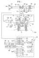
- FIG. 1 is a schematic view of an internal combustion engine 100 in an embodiment of the present invention.
- the internal combustion engine 100 is provided with an engine body 1 including a cylinder block 2 and a cylinder head 4.
- the internal combustion engine 100 is a spark ignition type internal combustion engine.
- the internal combustion engine 100 may also be a compression ignition type internal combustion engine (diesel engine).
- a piston 3 is arranged to reciprocate inside the cylinder block 2.
- a combustion chamber 5 is formed between the piston 3 and the cylinder head 4.
- the cylinder head 4 is formed with intake ports 7 and exhaust ports 9.
- the intake ports 7 and exhaust ports 9 are connected to the combustion chambers 5.
- An intake valve 6 is arranged at an end part of each intake port 7 and is formed to be able to open and close the intake port 7.
- An exhaust valve 8 is arranged at an end part of each exhaust port 9 and is formed to be able to open and close the exhaust port 9.
- the internal combustion engine 100 is provided with a variable valve timing mechanism B which can control the opening timing and the closing timing of each intake valve 6 and a variable valve timing mechanism C which can control the opening timing and the closing timing of each exhaust valve 8.
- the internal combustion engine 100 is comprised of fuel injectors 11 for feeding fuel to the combustion chambers 5 and spark plugs 10 for igniting the air-fuel mixture at the combustion chambers 5.
- the spark plugs 10 are fastened to the cylinder head 4.
- the fuel injectors 11 are arranged at the circumferential parts of the inner wall surfaces in the cylinder head 4 so as to directly inject fuel into the combustion chambers 5. That is, the internal combustion engine 100 is a cylinder injection type of internal combustion engine. Further, the internal combustion engine 100 uses fuel constituted by gasoline which has a stoichiometric air-fuel ratio of 14.6. However, in the internal combustion engine 100, other fuel may also be used.
- the internal combustion engine 100 is provided with a supercharger constituted by a turbocharger 101.
- the turbocharger 101 includes a turbine 102 which is arranged in the exhaust passage, a compressor 103 which is arranged in the intake passage, and a shaft which connects the turbine 102 and the compressor 103. If the flow of exhaust causes the turbine 102 to turn, the compressor 103 also turns and raises the pressure of the intake air. Therefore, the turbocharger 101 uses the energy of the exhaust gas to compress the intake air to increase the intake air amount.
- the intake port 7 is connected through a corresponding intake runner 13 to a surge tank 14.
- the surge tank 14 is connected through an intake pipe 15 to an outlet part of the compressor 103 of the turbocharger 101.
- a throttle valve 18 which is driven by a throttle valve drive actuator 17 is arranged.
- the throttle valve 18 can change the opening area of the intake passage by being turned by the throttle valve drive actuator 17.
- a cooler (intercooler) 106 which cools the intake air which is compressed by the turbocharger 101 is arranged.
- An inlet part of the compressor 103 is connected through the intake pipe 15 to an air cleaner 48.
- an air flowmeter 16 which detects the amount of intake air is arranged.
- An intake port 7, intake runner 13, intake pipe 15, etc. define an intake passage which guides air to the combustion chamber 5.
- the exhaust port 9 of each cylinder is connected to an exhaust manifold 19.
- the exhaust manifold 19 has a plurality of runners which are connected to the exhaust ports 9 and a header at which these runners are collected.
- the header of the exhaust manifold 19 is connected to the inlet part of the turbine 102 of the turbocharger 101.
- the outlet part of the turbine 102 is connected through an exhaust pipe 22 to a casing 21.
- the casing 21 has an exhaust purification catalyst 20 built into it.
- the casing 21 is connected to the exhaust pipe 23.
- An exhaust port 9, exhaust manifold 19, exhaust pipes 22, 23, etc. define an exhaust passage which discharges the exhaust gas which is produced due to combustion of the air-fuel mixture from a combustion chamber 5.
- an upstream side air-fuel ratio sensor 40 which detects the air-fuel ratio of the exhaust gas which flows through the inside of the exhaust pipe 22 (that is, the exhaust gas which flows into the exhaust purification catalyst 20) is arranged.
- the air-fuel ratio sensor 40 may be arranged at the upstream side of the turbine 102.
- a bypass passage 104 which bypasses the turbine 102 is arranged.
- a bypass valve which opens and closes the bypass passage 104 constituted by a wastegate valve 105 is arranged.
- the opening degree of the wastegate valve 105 By adjusting the opening degree of the wastegate valve 105, the amount of exhaust gas which runs through the turbine 102 can be adjusted. Therefore, by controlling the wastegate valve 105, the pressure of the intake air (supercharging pressure) can be controlled.
- the supercharging pressure control means which is used to control the supercharging pressure may be any mechanism besides a wastegate valve 105.
- the internal combustion engine 100 is provided with a pressure acquiring means for acquiring the supercharging pressure.
- the pressure acquiring means is for example a supercharging pressure sensor 50.
- the supercharging pressure sensor 50 is arranged in the intake passage at the downstream side from the throttle valve 18. Note that, the supercharging pressure is estimated from the operating state etc. of the internal combustion engine 100.
- the internal combustion engine 100 is provided with an electronic control unit 31 (ECU) which is comprised of a digital computer.
- the ECU 31 includes components which are connected with each other through bidirectional buses 32, such as a RAM (random access memory) 33, ROM (read only memory) 34, CPU (microprocessor) 35, input port 36, and output port 37.
- RAM random access memory
- ROM read only memory
- CPU microprocessor
- the output signal of the air flowmeter 16 is input through a corresponding AD converter 38 to the input port 36.
- the internal combustion engine 100 is provided with an accelerator pedal 42.
- the accelerator pedal 42 has a load sensor 43 connected to it.
- the load sensor 43 generates an output voltage which is proportional to the amount of depression of the accelerator pedal 42.
- the output voltage of the load sensor 43 is input through a corresponding AD converter 38 to the input port 36.
- the internal combustion engine 100 is provided with a crank angle sensor 44.
- the crank angle sensor 44 for example generates an output pulse every time the crankshaft rotates by a predetermined angle. This output pulse is input to the input port 36.
- the engine speed is calculated from the output pulse of this crank angle sensor 44. Further, the output of the crank angle sensor 44 can be used to detect the crank angle.
- the outputs of the supercharging pressure sensor 50 and air-fuel ratio sensor 40 are respectively input through corresponding AD converters 38 to the input port 36.
- the output port 37 of the ECU 31 is connected through corresponding drive circuits 45 to the spark plugs 10, fuel injectors 11, throttle valve drive actuator 17, wastegate valve 105, and variable valve timing mechanisms B and C.
- the ECU 31 can control the ignition timings of the spark plugs 10, the fuel injection timings and fuel injection amounts of the fuel injectors 11, the opening degree of the throttle valve 18, the opening degree of the wastegate valve 105, the opening timings and the closing timings of the intake valves 6, and the opening timings and the closing timings of the exhaust valves 8.
- the exhaust purification catalyst 20 is three-way catalysts which have oxygen storage abilities. Specifically, the exhaust purification catalyst 20 is comprised of carriers which are comprised of ceramic on which a precious metal which has a catalytic action (for example, platinum (Pt)) and a substance which has an oxygen storage ability (for example, ceria (CeO 2 )) are carried. The exhaust purification catalyst 20 exhibits a catalytic action of simultaneously removing unburned gas (HC, CO, etc.) and nitrogen oxides (NO x ) when reaching a predetermined activation temperature and, in addition, an oxygen storage ability.
- a precious metal which has a catalytic action for example, platinum (Pt)
- a substance which has an oxygen storage ability for example, ceria (CeO 2 )
- the exhaust purification catalyst 20 exhibits a catalytic action of simultaneously removing unburned gas (HC, CO, etc.) and nitrogen oxides (NO x ) when reaching a predetermined activation temperature and, in addition, an
- the exhaust purification catalyst 20 stores the oxygen in the exhaust gas when the air-fuel ratio of the exhaust gas which flows into the exhaust purification catalyst 20 is leaner than the stoichiometric air-fuel ratio (lean air-fuel ratio).
- the exhaust purification catalyst 20 releases the oxygen which is stored in the exhaust purification catalyst 20 when the inflowing exhaust gas has an air-fuel ratio which is richer than the stoichiometric air-fuel ratio (rich air-fuel ratio).
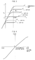
- the exhaust purification catalyst 20 has a catalytic action and oxygen storage ability and thereby have the action of removing NO X and unburned gas according to the stored amount of oxygen. That is, as shown in FIG. 2A , if the air-fuel ratio of the exhaust gas which flows into the exhaust purification catalyst 20 is a lean air-fuel ratio, when the stored amount of oxygen is small, the exhaust purification catalyst 20 stores the oxygen in the exhaust gas. Further, along with this, the NO X in the exhaust gas is removed by reduction. Further, if the stored amount of oxygen becomes larger, the exhaust gas which flows out from the exhaust purification catalyst 20 rapidly rises in concentration of oxygen and NO X at a certain stored amount near the maximum storable oxygen amount Cmax (in the figure, Cuplim).
- the characteristics of removal of NO X and unburned gas in the exhaust gas change depending on the air-fuel ratio of the exhaust gas which flows into the exhaust purification catalyst 20 and stored amount of oxygen.
- the exhaust purification catalyst 20 may also be catalysts different from the three-way catalyst.
- the air-fuel ratio sensor 40 has a voltage-current (V-I) characteristic such as shown in FIG. 3 .
- V-I voltage-current
- an output current I becomes larger the higher the exhaust air-fuel ratio (A/F) (the leaner).
- the V-I line at each exhaust air-fuel ratio has a region parallel to the V-axis, that is, a region where even if the sensor applied voltage changes, the output current does not change much at all. This voltage region is called the "limit current region”.
- the current at this time is called the "limit current”.
- the limit current region and the limit current when the exhaust air-fuel ratio is 18 are respectively shown by W 18 and I 18 .
- FIG. 4 is a view showing a relationship between an exhaust air-fuel ratio and an output current I when making an applied voltage constant at about 0.45V.
- the air-fuel ratio sensor 40 the higher the exhaust air-fuel ratio (that is, the leaner), the larger the output current I from the air-fuel ratio sensor 40.
- the air-fuel ratio sensor 40 is configured so that when the exhaust air-fuel ratio is the stoichiometric air-fuel ratio, the output current I becomes zero. Therefore, the air-fuel ratio sensor 40 can continuously (linearly) detect the exhaust air-fuel ratio.
- the air-fuel ratio sensor 40 may also be an air-fuel ratio sensor other than a limit current type.
- the internal combustion engine 100 is further provided with an air-fuel ratio control device.
- the air-fuel ratio control device controls the amount of fuel supplied to the combustion chamber 5, that is, a fuel injection amount from the fuel injector 11, by feedback based on an output air-fuel ratio of the air-fuel ratio sensor 40 so that the output air-fuel ratio of the air-fuel ratio sensor 40 becomes a target air-fuel ratio.
- the target air-fuel ratio is for example the stoichiometric air-fuel ratio (14.6).
- the output air-fuel ratio means the air-fuel ratio corresponding to the output value of the air-fuel ratio sensor.
- the target air-fuel ratio does not have to be made constant and may also be changed according to the operating state etc.
- the target air-fuel ratio may be alternately switched between an air-fuel ratio leaner than the stoichiometric air-fuel ratio and an air-fuel ratio richer than the stoichiometric air-fuel ratio.
- the target air-fuel ratio may be set based on the output air-fuel ratio of the downstream side air-fuel ratio sensor (not shown) arranged at the downstream side of the exhaust purification catalyst 20.
- the downstream side air-fuel ratio sensor detects the air-fuel ratio of the exhaust gas flowing out from the exhaust purification catalyst 20.
- valve overlap between the intake valve and the exhaust valve means the partial overlap of the opening time period of the intake valve 6 and the opening time period of the exhaust valve 8.
- the ECU 31 can control at least one of the variable valve timing mechanism B of the intake valve 6 and the variable valve timing mechanism C of the exhaust valve 8 so as to cause valve overlap and can change the valve overlap amount (that is, time period during which intake valve 6 and exhaust valve 8 are both opened). Specifically, the valve overlap amount is changed by at least one of changing the opening timing of the intake valve 6 and changing the closing timing of the exhaust valve 8.
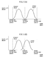
- FIGS. 5A and 5B are views schematically showing examples of opening time periods of the exhaust valve 8 and intake valve 6.
- the closing timing of the exhaust valve 8 and the opening timing of the intake valve 6 match at exhaust top dead center so valve overlap does not occur.
- the opening time period of the exhaust valve 8 and the opening time period of the intake valve 6 overlap and valve overlap occurs.
- scavenging is used.
- the amount of exhaust gas increases and the speed of the turbine 102 of the turbocharger 101 is raised.
- the pressure of the intake air (supercharging pressure) is raised and the amount of intake air is made to increase.
- the amount of fuel supplied to the combustion chamber 5 is controlled so that an average air-fuel ratio of the exhaust gas, including air expelled from the intake passage through a cylinder to the exhaust passage, becomes the target air-fuel ratio.
- the expulsion of air causes the air in a cylinder to decrease, so the combustion air-fuel ratio in the cylinder becomes richer than the target air-fuel ratio. Therefore, if valve overlap causes scavenging, at each cylinder, air is expelled through the exhaust passage at the intake stroke and exhaust gas richer than the target air-fuel ratio is discharged into the exhaust passage at the exhaust stroke.
- the air-fuel ratio of the exhaust gas exhausted from each cylinder alternately changes between an air-fuel ratio leaner than the target air-fuel ratio and an air-fuel ratio richer than the target air-fuel ratio.
- the average air-fuel ratio of the exhaust gas discharged from all cylinders will never greatly deviate from the target air-fuel ratio.
- the output of the air-fuel ratio sensor 40 becomes leaner than the target air-fuel ratio. For this reason, the amount of fuel supplied to the combustion chamber 5 is increased by feedback control of the air-fuel ratio based on the output of the air-fuel ratio sensor 40.
- a time lag occurs before the air-fuel ratio of the exhaust gas reaching the exhaust purification catalyst 20 changes to the rich side. For this reason, even with such feedback control, deterioration of the exhaust emission right after scavenging cannot be suppressed.
- valve overlap causes scavenging
- fuel is supplied to the exhaust passage only at the initial cycle after scavenging. If the fuel supplied to the exhaust passage reaches the exhaust purification catalyst 20, oxygen stored at the exhaust purification catalyst 20 is released.
- the exhaust purification catalyst 20 by supplying fuel to the exhaust passage right after scavenging, it is possible to keep the expulsion of air right after scavenging from causing the exhaust purification catalyst 20 to rapidly increase in the oxygen storage amount and in turn keep the exhaust emission from deteriorating right after scavenging.
- the "initial cycle after scavenging" means a single cycle comprised of the stroke at which scavenging initially occurs and the three strokes following that stroke.
- the internal combustion engine 100 comprises a fuel supplying means for supplying fuel to the exhaust passage for performing the above control.
- the fuel supplying means is, for example a cylinder fuel injector 11 directly injecting fuel into a cylinder.
- the cylinder fuel injector 11 can inject fuel in the exhaust stroke to thereby supply fuel (unburned fuel) to the exhaust passage.
- the fuel supplying means may be an exhaust fuel injector (not shown) arranged at the exhaust passage at the upstream side of the exhaust purification catalyst 20, for example, arranged at the exhaust port 9.
- the exhaust fuel injector can directly supply fuel to the exhaust passage.
- the internal combustion engine 100 may be a port injection type internal combustion engine. In this case, the fuel injector is arranged near the intake port 7 so as to inject fuel into the intake port 7.
- the internal combustion engine 100 further comprises a scavenging amount calculating means for calculating the scavenging amount.
- the amount of fuel supplied by the fuel supplying means to the exhaust passage is the amount of fuel so that the air-fuel ratio of the air-fuel mixture formed when that amount of fuel is supplied with respect to the scavenging amount of air calculated by the scavenging amount calculating means becomes the target air-fuel ratio of the exhaust gas flowing into the exhaust purification catalyst 20. Due to this, it is possible to make the exhaust air-fuel ratio right after scavenging approach the target air-fuel ratio.
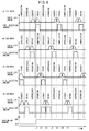
- FIG. 6 is a time chart of the fuel injection amounts and the valve lift amounts of the exhaust valve 8 and intake valve 6 at the #1 cylinder, the #2 cylinder, the #3 cylinder, and the #4 cylinder in the case of scavenging occurring.
- the internal combustion engine 100 comprises the four cylinders of the #1 cylinder, the #2 cylinder, the #3 cylinder, and the #4 cylinder. Further, in the example of FIG. 6 , the engine speed of the internal combustion engine 100 is made constant.
- variable valve timing mechanism C retards the phase angle of the exhaust valve 8 and the variable valve timing mechanism B advances the phase angle of the intake valve 6 whereby the valve overlap amount is made to increase.
- phase angle means the angle at the center of the operating angle.
- scavenging initially occurs at the intake stroke of the #3 cylinder between the time t2 and the time t3. After that, scavenging occurs in the intake stroke of the #4 cylinder between the time t3 and the time t4, scavenging occurs in the intake stroke of the #2 cylinder between the time t4 and the time t5, and scavenging occurs in the intake stroke of the #1 cylinder between the time t5 and the time t6.
- the exhaust purification catalyst 20 will rapidly increase in oxygen storage amount. Therefore, in the example of FIG. 6 , in the exhaust stroke of the #4 cylinder between the time t2 and the time t3, that is, at the initial exhaust stroke at all cylinders after scavenging, fuel is injected by the fuel injector 11 into the cylinder. As a result, fuel is supplied to the exhaust passage.
- the amount of fuel supplied to the exhaust passage at this time is the estimated value of the total of the amounts of air expelled by scavenging at each cylinder at the initial cycle after scavenging (scavenging amount) divided by the target air-fuel ratio of the exhaust gas flowing into the exhaust purification catalyst 20 (for example stoichiometric air-fuel ratio (14.6)).
- scavenging amount the target air-fuel ratio of the exhaust gas flowing into the exhaust purification catalyst 20 (for example stoichiometric air-fuel ratio (14.6)).
- the first cycle after the scavenging in the example of FIG. 6 , is one cycle in each cylinder between the time t2 and the time t6.
- the exhaust air-fuel ratio can be made to approach the target air-fuel ratio.
- the exhaust purification catalyst 20 is kept from rapidly increasing in oxygen storage amount right after scavenging and in turn the exhaust emission is kept from deteriorating right after scavenging.
- the fuel may also be supplied to the exhaust passage at an exhaust stroke of other than the #4 cylinder at the initial cycle after scavenging. Specifically, the fuel may also be supplied at the exhaust stroke at the #2 cylinder between the time t3 and the time t4, the exhaust stroke at the #1 cylinder between the time t4 and the time t5, or the exhaust stroke at the #3 cylinder between the time t5 and the time t6. That is, in the present embodiment, the fuel supplying means supplies fuel to the exhaust passage when at least part of the cylinders among the plurality of cylinders are in the first exhaust stroke after scavenging.
- scavenging occurs at the intake stroke of the #3 cylinder between the time t6 and the time t7.
- exhaust stroke of the #3 cylinder right before this intake stroke exhaust gas made rich in combustion air-fuel ratio in the cylinder due to the expulsion of air is discharged. Therefore, in the initial cycle after scavenging and on, air is expelled from each cylinder in the state where exhaust gas richer than the target air-fuel ratio is present at the exhaust passage, so the expulsion of air is kept from causing the exhaust purification catalyst 20 to rapidly increase in oxygen storage amount.
- the air-fuel ratio control device may make the target air-fuel ratio after scavenging richer than the target air-fuel ratio before scavenging. By doing this, the combustion air-fuel ratio in a cylinder during scavenging becomes richer, so at the initial cycle after scavenging and on, the exhaust purification catalyst 20 can be more effectively kept from rapidly increasing in oxygen storage amount.
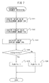
- FIG. 7 is a flow chart showing the control routine of processing for judgment of scavenging in the first embodiment of the present invention.
- the illustrated control routine is executed by interruption at constant time intervals so as to judging the occurrence of scavenging.
- an intake valve displacement amount IVA is acquired.
- the intake valve displacement amount IVA is the amount of change from the initial value of the opening timing of the intake valve 6.
- the sign of the intake valve displacement amount IVA is made plus when the opening timing of the intake valve 6 is advanced from the initial value and is made minus when the opening timing of the intake valve 6 is retarded from the initial value.
- an exhaust valve displacement amount EVA is acquired.
- the exhaust valve displacement amount EVA is the amount of change from the initial value of the closing timing of the exhaust valve 8.
- the sign of the exhaust valve displacement amount EVA is made plus when the closing timing of the exhaust valve 8 is retarded from the initial value and is made minus when the closing timing of the exhaust valve 8 is advanced from the initial value.
- valve overlap amount between the intake valve 6 and the exhaust valve 8 is calculated.
- INT indicates the initial value of the valve overlap amount.
- step S14 it is judged if the valve overlap amount VOA calculated at step S13 is a predetermined valve overlap reference amount VOAref or more.
- the valve overlap reference amount VOAref is the minimum value of the valve overlap amount wherein it is estimated that scavenging will occur, and is found by experiments or calculation. If it is judged that the valve overlap amount VOA is the valve overlap reference amount VOAref or more, the routine proceeds to step S15.
- the scavenging judgment flag Fs is set to "1". The scavenging judgment flag Fs is set to zero when it is estimated that scavenging has not occurred and is set to "1" when it is estimated that scavenging will occur. After step S15, the present control routine is ended.
- step S14 if, at step S14, it is judged that the valve overlap amount VOA is less than the valve overlap reference amount VOAref, the routine proceeds to step S16.
- step S16 the scavenging judgment flag Fs is set to zero. After step S16, the present control routine is ended.
- FIG. 8 is a flow chart showing a control routine of processing for supplying fuel in the first embodiment of the present invention.
- the illustrated control routine is executed by interruption at constant time intervals.
- a scavenging judgment flag Fs is acquired.
- step S22 it is judged if the scavenging judgment flag Fs has changed from zero to "1". If the scavenging judgment flag Fs acquired at step S21 of the previous control routine is zero and the scavenging judgment flag Fs acquired at step S21 of the current control routine is "1", it is judged that the scavenging judgment flag Fs has changed from zero to "1” and the routine proceeds to step S23. On the other hand, if it is judged that the scavenging judgment flag Fs has not changed from zero to "1", fuel is not supplied to the exhaust passage and the present control routine is ended.
- the scavenging amount SBA per one cylinder is calculated.
- the scavenging amount SBA is, for example, calculated based on the valve overlap amount VOA, differential pressure between the intake pressure and exhaust pressure, engine speed, and intake air amount.
- the valve overlap amount VOA is calculated at step S13 of the control routine of FIG. 7 .
- the engine speed is calculated from the output of the crank angle sensor 44, while the intake air amount is detected by the air flow meter 16.
- the intake pressure is, for example, directly detected by a supercharging sensor 50 or is calculated by known model calculations based on the output of an intake temperature sensor provided in the intake passage at the downstream side of the throttle valve 18, the output of the air flow meter 16, the opening degree of the throttle valve 18, etc.
- the exhaust pressure is, for example, directly detected by an exhaust pressure sensor provided at the exhaust manifold 19 or is calculated based on a map shown as a function of the engine speed and intake pressure. Specifically, in the above map, the exhaust pressure is shown as becoming higher the higher the engine speed and is shown as becoming higher the higher the intake pressure.
- the scavenging amount SBA may be calculated based on a map shown as a function of the valve overlap amount VOA, differential pressure of the intake pressure and exhaust pressure, engine speed, and intake air amount. Specifically, in the above map, the scavenging amount SBA is shown as becoming larger the larger the valve overlap amount VOA, is shown as becoming larger the larger the differential pressure of the intake pressure and the exhaust pressure, is shown as becoming larger the lower the engine speed, and is shown as becoming larger the larger the intake air amount.
- the amount of fuel to be supplied to the exhaust passage is calculated.
- the supplied fuel amount SFA is for example calculated by the following formula (2):
- SFA SBA / TAF ⁇ CN
- TAF indicates the target air-fuel ratio of the exhaust gas flowing into the exhaust purification catalyst 20 (for example stoichiometric air-fuel ratio (14.6))
- CN indicates the number of cylinders of the internal combustion engine 100.
- step S25 fuel of the supplied fuel amount SFA calculated at step S24 is supplied by the fuel supplying means to the exhaust passage.
- the fuel supplying means is the cylinder fuel injector 11 or exhaust fuel injector.
- the fuel is supplied to the exhaust passage only at the initial cycle after scavenging.
- the fuel is supplied to the exhaust passage when at least part of the cylinders among the plurality of cylinders are in the initial exhaust stroke after scavenging.
- the fuel may also be supplied to the exhaust passage a plurality of times at the initial cycle after scavenging. In this case, in one fuel supply operation, an amount of fuel of the supplied fuel amount SFA divided by the number of times of supply is supplied to the exhaust passage.
- the present control routine is ended.
- FIG. 9 and FIG. 10 a second embodiment of the present invention will be explained.
- the configuration and control of the internal combustion engine of the second embodiment are basically the same as the internal combustion engine of the first embodiment, so in the following explanation, mainly parts differing from the first embodiment will be explained.
- the amount of oxygen released from the exhaust purification catalyst 20 due to the supplied fuel becomes smaller, so it is not possible to effectively suppress a rapid increase in oxygen storage amount of the exhaust purification catalyst 20 due to the expulsion of air.
- the exhaust purification catalyst 20 rapidly decreases in oxygen storage amount, so unburned gas is liable to flow out from the exhaust purification catalyst 20.
- the fuel supplying means supplies fuel to the exhaust passage when each cylinder is in the initial exhaust stroke after scavenging.
- the amount of fuel supplied at each exhaust stroke is the estimated value of the amount of air expelled due to the scavenging at each cylinder at the initial cycle after scavenging (scavenging amount) divided by the target air-fuel ratio of the exhaust gas flowing into the exhaust purification catalyst 20 (for example, the stoichiometric air-fuel ratio (14.6)).
- a suitable amount of fuel corresponding to the scavenging amount is supplied at a timing at which air is expelled from each cylinder, so exhaust emission right after scavenging can be more effectively suppressed.
- FIG. 9 is a time chart of the fuel injection amounts and the valve lift amounts of the exhaust valve 8 and intake valve 6 at the #1 cylinder, the #2 cylinder, the #3 cylinder, and the #4 cylinder in the case of scavenging occurring.
- the internal combustion engine 100 comprises the four cylinders of the #1 cylinder, the #2 cylinder, the #3 cylinder, and the #4 cylinder. Further, in the example of FIG. 9 , the engine speed of the internal combustion engine 100 is made constant.
- scavenging first occurs at the intake stroke of the #3 cylinder between the time t2 and the time t3. After that, scavenging occurs at the intake stroke of the #4 cylinder between the time t3 and the time t4, scavenging occurs at the intake stroke of the #2 cylinder between the time t4 and the time t5, and scavenging occurs at the intake stroke of the #1 cylinder between the time t5 and the time t6.
- the amount of fuel supplied to the exhaust passage at each exhaust stroke is the estimated value of the amount of air expelled by the scavenging at each cylinder at the initial cycle after scavenging (scavenging amount) divided by the target air-fuel ratio of the exhaust gas flowing into the exhaust purification catalyst 20 (for example stoichiometric air-fuel ratio (14.6)).
- scavenging amount the target air-fuel ratio of the exhaust gas flowing into the exhaust purification catalyst 20
- the air-fuel ratio control during scavenging in the second embodiment will be explained in detail.
- the control routine shown in FIG. 7 is performed so as to judge the occurrence of scavenging.
- FIG. 10 is a flow chart showing a control routine of processing for supplying fuel in the second embodiment of the present invention.
- the illustrated control routine is executed by interruption at constant time intervals.
- Step S31 to step S33 are similar to step S21 to step S23 in FIG. 8 , so explanations will be omitted.
- the amount of fuel supplied to the exhaust passage is calculated.
- the supplied fuel amount SFA is, for example, calculated by the following formula (3).
- SFA SBA / TAF
- TAF indicates the target air-fuel ratio of the exhaust gas flowing into the exhaust purification catalyst 20 (for example stoichiometric air-fuel ratio (14.6)).
- step S35 fuel of the supplied fuel amount SFA calculated at step S34 is supplied by the fuel supplying means to the exhaust passage.
- the fuel supplying means is the cylinder fuel injector 11 or exhaust fuel injector. The fuel is supplied to the exhaust passage when each cylinder is in the initial exhaust stroke after scavenging.
- step S35 the present control routine is ended.
Landscapes
- Engineering & Computer Science (AREA)
- Chemical & Material Sciences (AREA)
- Combustion & Propulsion (AREA)
- Mechanical Engineering (AREA)
- General Engineering & Computer Science (AREA)
- Chemical Kinetics & Catalysis (AREA)
- Health & Medical Sciences (AREA)
- Toxicology (AREA)
- Materials Engineering (AREA)
- Electrical Control Of Air Or Fuel Supplied To Internal-Combustion Engine (AREA)
- Output Control And Ontrol Of Special Type Engine (AREA)
- Exhaust Gas After Treatment (AREA)
- Combined Controls Of Internal Combustion Engines (AREA)
Abstract
Description
- The present invention relates to an internal combustion engine.
- In an internal combustion engine, if generating valve overlap between intake valve and exhaust valve when the pressure inside an intake port is higher than the pressure inside an exhaust port, air is blown from the intake passage through the cylinder to the exhaust passage in what is known as "scavenging". For example, in an internal combustion engine provided with a supercharger such as a turbocharger, scavenging is intentionally caused if the amount of intake air is insufficient for the requested torque. By causing scavenging, the amount of exhaust gas increases and the speed of the turbine of the supercharger is raised. As a result, the pressure of the intake air is raised and the amount of intake air is increased.
- Known in the past has been an internal combustion engine configured to provide an air-fuel ratio sensor at the upstream side of an exhaust purification catalyst in an exhaust passage of the internal combustion engine and control the amount of fuel fed to a combustion chamber of the internal combustion engine so that the output of this air-fuel ratio sensor matches a target air-fuel ratio (for example stoichiometric air-fuel ratio (14.6)) (for example, PLT 1).
- In such control, during scavenging, the amount of fuel fed to a combustion chamber is controlled so that the average air-fuel ratio of the exhaust gas, including the air expelled from the intake passage through the cylinder to the exhaust passage, becomes a target air-fuel ratio. In this case, during scavenging, the air in the cylinder is decreased by the expulsion of air, so the combustion air-fuel ratio in the cylinder becomes richer than the target air-fuel ratio. Therefore, if valve overlap causes scavenging, in each cylinder, air will be expelled through the exhaust passage in the intake stroke and exhaust gas richer than the target air-fuel ratio will be exhausted into the exhaust passage in the exhaust stroke. In other words, the air-fuel ratio of the exhaust gas exhausted from each cylinder will alternately change between an air-fuel ratio leaner than the target air-fuel ratio and an air-fuel ratio richer than the target air-fuel ratio. In this case, the average air-fuel ratio of the exhaust gas exhausted from all of the cylinders will never greatly deviate from the target air-fuel ratio.
- PLT 1.
Japanese Patent Publication No. 2013-238111A PLT 2.Japanese Patent Publication No. 2008-223678A - However, in each cylinder, in the exhaust stroke right before the intake stroke where scavenging initially occurs, the combustion gas of the air-fuel mixture in the state before the expulsion of air causes the combustion air-fuel ratio to become richer than the target air-fuel ratio, that is, exhaust gas of substantially the target air-fuel ratio, will be exhausted. Therefore, at each cylinder, when scavenging initially occurs, air is expelled through the exhaust passage in a state where there is no exhaust gas richer than the target air-fuel ratio present in the exhaust passage. For this reason, right after scavenging, the average air-fuel ratio of the exhaust gas exhausted from all of the cylinders becomes leaner than the target air-fuel ratio and the exhaust purification catalyst rapidly increases in oxygen storage amount. As a result, the exhaust purification catalyst is liable to fall in efficiency of removal of NOX and the exhaust emission is liable to deteriorate.
- Further, right after scavenging, the output of an upstream side air-fuel ratio sensor arranged at an upstream side of the exhaust purification catalyst becomes leaner than the target air-fuel ratio. For this reason, if feedback control of the air-fuel ratio is performed based on the output of the upstream side air-fuel ratio sensor, the amount of fuel supplied to a combustion chamber will be increased. However, even if increasing the amount of fuel, a time lag occurs until the air-fuel ratio of the exhaust gas reaching the exhaust purification catalyst changes to the rich side. For this reason, even if using such feedback control, deterioration of the exhaust emission right after scavenging cannot be suppressed.
- Therefore, in view of the above problem, an object of the present invention is to provide an internal combustion engine which can suppress the deterioration of exhaust emission immediately after scavenging.
- In order to solve the above problem, in the present disclosure, there is provided an internal combustion engine comprising: a catalyst arranged in an exhaust passage and able to store oxygen, a variable valve timing mechanism able to change a valve overlap amount between an intake valve and an exhaust valve, and a fuel supplying means for feeding fuel to the exhaust passage, wherein the fuel supplying means feeds fuel to the exhaust passage only in an initial cycle after scavenging where valve overlap causes air to be expelled from an intake passage through a cylinder to the exhaust passage if such scavenging occurs.
- In some embodiments, the internal combustion engine comprises a plurality of cylinders, and the fuel supplying means supplies fuel to the exhaust passage when at least part of the plurality of cylinders are at an initial exhaust stroke after scavenging, in the first invention.
- In some embodiments, the fuel supplying means supplies fuel to the exhaust passage when each cylinder is at an initial exhaust stroke after scavenging, in the second invention.
- In some embodiments, the internal combustion engine further comprises a scavenging amount calculating means for calculating a scavenging amount, and the amount of the fuel supplied by the fuel supplying means to the exhaust passage is an amount of fuel whereby an air-fuel ratio of an air-fuel mixture formed when supplying the amount of fuel with respect to the scavenging amount of air calculated by the scavenging amount calculating means becomes a target air-fuel ratio of exhaust gas flowing into the catalyst, in any one of the first to third inventions.
- In some embodiments, the scavenging control device increases the upper limit when an air-fuel ratio of the lean judged air-fuel ratio or more has not been detected by the downstream side air-fuel ratio sensor regardless of having controlled the valve overlap amount so that the scavenging amount becomes the upper limit, in any one of the first to fourth inventions.
- According to the present invention, there is provided an internal combustion engine which can suppress the deterioration of exhaust emission immediately after scavenging.
-
- [
FIG. 1] FIG. 1 is a schematic view of an internal combustion engine in an embodiment of the present invention. [FIG. 2A] FIG. 2A is a view showing the relationship between an oxygen storage amount of an exhaust purification catalyst and NOx concentration in exhaust gas flowing out from the exhaust purification catalyst. - [
FIG. 2B] FIG. 2B is a view showing the relationship between an oxygen storage amount of an exhaust purification catalyst and HC and CO concentration in exhaust gas flowing out from the exhaust purification catalyst. - [
FIG. 3] FIG. 3 is a view showing a relationship between a sensor applied voltage and an output current at each exhaust air-fuel ratio. - [
FIG. 4] FIG. 4 is a view showing a relationship between an exhaust air-fuel ratio and output current when making the sensor applied voltage constant. - [
FIG. 5A] FIG. 5A is a view schematically showing an example of opening time periods of an exhaust valve and intake valve. - [
FIG. 5B] FIG. 5B is a view schematically showing an example of opening time periods of an exhaust valve and intake valve. - [
FIG. 6] FIG. 6 is a time chart of a fuel injection amount and valve lift amounts of an exhaust valve and intake valve at each cylinder in the case where scavenging occurs. - [
FIG. 7] FIG. 7 is a flow chart showing a control routine of processing for judging scavenging in a first embodiment of the present invention. - [
FIG. 8] FIG. 8 is a flow chart showing a control routine of processing for supplying fuel in the first embodiment of the present invention. - [
FIG. 9] FIG. 9 is a time chart of a fuel injection amount and valve lift amounts of an exhaust valve and intake valve at each cylinder in the case where scavenging occurs. - [
FIG. 10] FIG. 10 is a flow chart showing a control routine of processing for judging scavenging in a second embodiment of the present invention. - Below, referring to the drawings, embodiments of the present invention will be explained in detail.
- First, referring to
FIG. 1 to FIG. 8 , a first embodiment of the present invention will be explained. -
FIG. 1 is a schematic view of aninternal combustion engine 100 in an embodiment of the present invention. Theinternal combustion engine 100 is provided with anengine body 1 including acylinder block 2 and acylinder head 4. In the present embodiment, theinternal combustion engine 100 is a spark ignition type internal combustion engine. Note that, theinternal combustion engine 100 may also be a compression ignition type internal combustion engine (diesel engine). Inside of thecylinder block 2, apiston 3 is arranged to reciprocate inside thecylinder block 2. - A
combustion chamber 5 is formed between thepiston 3 and thecylinder head 4. Thecylinder head 4 is formed withintake ports 7 andexhaust ports 9. Theintake ports 7 andexhaust ports 9 are connected to thecombustion chambers 5. Anintake valve 6 is arranged at an end part of eachintake port 7 and is formed to be able to open and close theintake port 7. Anexhaust valve 8 is arranged at an end part of eachexhaust port 9 and is formed to be able to open and close theexhaust port 9. Further, theinternal combustion engine 100 is provided with a variable valve timing mechanism B which can control the opening timing and the closing timing of eachintake valve 6 and a variable valve timing mechanism C which can control the opening timing and the closing timing of eachexhaust valve 8. - The
internal combustion engine 100 is comprised offuel injectors 11 for feeding fuel to thecombustion chambers 5 andspark plugs 10 for igniting the air-fuel mixture at thecombustion chambers 5. The spark plugs 10 are fastened to thecylinder head 4. Thefuel injectors 11 are arranged at the circumferential parts of the inner wall surfaces in thecylinder head 4 so as to directly inject fuel into thecombustion chambers 5. That is, theinternal combustion engine 100 is a cylinder injection type of internal combustion engine. Further, theinternal combustion engine 100 uses fuel constituted by gasoline which has a stoichiometric air-fuel ratio of 14.6. However, in theinternal combustion engine 100, other fuel may also be used. - The
internal combustion engine 100 is provided with a supercharger constituted by aturbocharger 101. Theturbocharger 101 includes aturbine 102 which is arranged in the exhaust passage, acompressor 103 which is arranged in the intake passage, and a shaft which connects theturbine 102 and thecompressor 103. If the flow of exhaust causes theturbine 102 to turn, thecompressor 103 also turns and raises the pressure of the intake air. Therefore, theturbocharger 101 uses the energy of the exhaust gas to compress the intake air to increase the intake air amount. - The
intake port 7 is connected through acorresponding intake runner 13 to asurge tank 14. Thesurge tank 14 is connected through anintake pipe 15 to an outlet part of thecompressor 103 of theturbocharger 101. At the inside of theintake pipe 15 which connects thesurge tank 14 andcompressor 103, athrottle valve 18 which is driven by a throttlevalve drive actuator 17 is arranged. Thethrottle valve 18 can change the opening area of the intake passage by being turned by the throttlevalve drive actuator 17. Further, in theintake pipe 15 between thecompressor 103 andthrottle valve 18, a cooler (intercooler) 106 which cools the intake air which is compressed by theturbocharger 101 is arranged. - An inlet part of the
compressor 103 is connected through theintake pipe 15 to anair cleaner 48. At the inside of theintake pipe 15 between theair cleaner 48 andcompressor 103, anair flowmeter 16 which detects the amount of intake air is arranged. Anintake port 7,intake runner 13,intake pipe 15, etc. define an intake passage which guides air to thecombustion chamber 5. - On the other hand, the
exhaust port 9 of each cylinder is connected to anexhaust manifold 19. Theexhaust manifold 19 has a plurality of runners which are connected to theexhaust ports 9 and a header at which these runners are collected. The header of theexhaust manifold 19 is connected to the inlet part of theturbine 102 of theturbocharger 101. The outlet part of theturbine 102 is connected through anexhaust pipe 22 to acasing 21. Thecasing 21 has anexhaust purification catalyst 20 built into it. Thecasing 21 is connected to theexhaust pipe 23. Anexhaust port 9,exhaust manifold 19,exhaust pipes combustion chamber 5. - Further, inside the
exhaust pipe 22 between theturbine 102 and thecasing 21, an upstream side air-fuel ratio sensor 40 which detects the air-fuel ratio of the exhaust gas which flows through the inside of the exhaust pipe 22 (that is, the exhaust gas which flows into the exhaust purification catalyst 20) is arranged. Note that the air-fuel ratio sensor 40 may be arranged at the upstream side of theturbine 102. - Between the
exhaust manifold 19 upstream of theturbine 102 and theexhaust pipe 22 downstream of theturbine 102, abypass passage 104 which bypasses theturbine 102 is arranged. At thebypass passage 104, a bypass valve which opens and closes thebypass passage 104 constituted by awastegate valve 105 is arranged. By adjusting the opening degree of thewastegate valve 105, the amount of exhaust gas which runs through theturbine 102 can be adjusted. Therefore, by controlling thewastegate valve 105, the pressure of the intake air (supercharging pressure) can be controlled. Note that, the supercharging pressure control means which is used to control the supercharging pressure may be any mechanism besides awastegate valve 105. - The
internal combustion engine 100 is provided with a pressure acquiring means for acquiring the supercharging pressure. The pressure acquiring means is for example a superchargingpressure sensor 50. The superchargingpressure sensor 50 is arranged in the intake passage at the downstream side from thethrottle valve 18. Note that, the supercharging pressure is estimated from the operating state etc. of theinternal combustion engine 100. - The
internal combustion engine 100 is provided with an electronic control unit 31 (ECU) which is comprised of a digital computer. TheECU 31 includes components which are connected with each other throughbidirectional buses 32, such as a RAM (random access memory) 33, ROM (read only memory) 34, CPU (microprocessor) 35,input port 36, andoutput port 37. - The output signal of the
air flowmeter 16 is input through acorresponding AD converter 38 to theinput port 36. Theinternal combustion engine 100 is provided with anaccelerator pedal 42. Theaccelerator pedal 42 has aload sensor 43 connected to it. Theload sensor 43 generates an output voltage which is proportional to the amount of depression of theaccelerator pedal 42. The output voltage of theload sensor 43 is input through acorresponding AD converter 38 to theinput port 36. - The
internal combustion engine 100 is provided with acrank angle sensor 44. Thecrank angle sensor 44 for example generates an output pulse every time the crankshaft rotates by a predetermined angle. This output pulse is input to theinput port 36. In theCPU 35, the engine speed is calculated from the output pulse of this crankangle sensor 44. Further, the output of thecrank angle sensor 44 can be used to detect the crank angle. The outputs of the superchargingpressure sensor 50 and air-fuel ratio sensor 40 are respectively input throughcorresponding AD converters 38 to theinput port 36. - The
output port 37 of theECU 31 is connected throughcorresponding drive circuits 45 to the spark plugs 10,fuel injectors 11, throttlevalve drive actuator 17,wastegate valve 105, and variable valve timing mechanisms B andC. The ECU 31 can control the ignition timings of the spark plugs 10, the fuel injection timings and fuel injection amounts of thefuel injectors 11, the opening degree of thethrottle valve 18, the opening degree of thewastegate valve 105, the opening timings and the closing timings of theintake valves 6, and the opening timings and the closing timings of theexhaust valves 8. - The
exhaust purification catalyst 20 is three-way catalysts which have oxygen storage abilities. Specifically, theexhaust purification catalyst 20 is comprised of carriers which are comprised of ceramic on which a precious metal which has a catalytic action (for example, platinum (Pt)) and a substance which has an oxygen storage ability (for example, ceria (CeO2)) are carried. Theexhaust purification catalyst 20 exhibits a catalytic action of simultaneously removing unburned gas (HC, CO, etc.) and nitrogen oxides (NOx) when reaching a predetermined activation temperature and, in addition, an oxygen storage ability. - According to the oxygen storage ability of the
exhaust purification catalyst 20, theexhaust purification catalyst 20 stores the oxygen in the exhaust gas when the air-fuel ratio of the exhaust gas which flows into theexhaust purification catalyst 20 is leaner than the stoichiometric air-fuel ratio (lean air-fuel ratio). On the other hand, theexhaust purification catalyst 20 releases the oxygen which is stored in theexhaust purification catalyst 20 when the inflowing exhaust gas has an air-fuel ratio which is richer than the stoichiometric air-fuel ratio (rich air-fuel ratio). - The
exhaust purification catalyst 20 has a catalytic action and oxygen storage ability and thereby have the action of removing NOX and unburned gas according to the stored amount of oxygen. That is, as shown inFIG. 2A , if the air-fuel ratio of the exhaust gas which flows into theexhaust purification catalyst 20 is a lean air-fuel ratio, when the stored amount of oxygen is small, theexhaust purification catalyst 20 stores the oxygen in the exhaust gas. Further, along with this, the NOX in the exhaust gas is removed by reduction. Further, if the stored amount of oxygen becomes larger, the exhaust gas which flows out from theexhaust purification catalyst 20 rapidly rises in concentration of oxygen and NOX at a certain stored amount near the maximum storable oxygen amount Cmax (in the figure, Cuplim). - On the other hand, as shown in
FIG. 2B , if the air-fuel ratio of the exhaust gas which flows into theexhaust purification catalyst 20 is the rich air-fuel ratio, when the stored amount of oxygen is large, the oxygen which is stored in theexhaust purification catalyst 20 is released, and the unburned gas in the exhaust gas is removed by oxidation. Further, if the stored amount of oxygen becomes small, the exhaust gas which flows out from theexhaust purification catalyst 20 rapidly rises in concentration of unburned gas at a certain stored amount near zero (in the figure, Clowlim). - In the above way, according to the
exhaust purification catalyst 20 which are used in the present embodiment, the characteristics of removal of NOX and unburned gas in the exhaust gas change depending on the air-fuel ratio of the exhaust gas which flows into theexhaust purification catalyst 20 and stored amount of oxygen. Note that, if having a catalytic action and oxygen storage ability, theexhaust purification catalyst 20 may also be catalysts different from the three-way catalyst. - The air-
fuel ratio sensor 40 has a voltage-current (V-I) characteristic such as shown inFIG. 3 . As will be understood fromFIG. 3 , an output current I becomes larger the higher the exhaust air-fuel ratio (A/F) (the leaner). Further, the V-I line at each exhaust air-fuel ratio has a region parallel to the V-axis, that is, a region where even if the sensor applied voltage changes, the output current does not change much at all. This voltage region is called the "limit current region". The current at this time is called the "limit current". InFIG. 3 , the limit current region and the limit current when the exhaust air-fuel ratio is 18 are respectively shown by W18 and I18. -
FIG. 4 is a view showing a relationship between an exhaust air-fuel ratio and an output current I when making an applied voltage constant at about 0.45V. As will be understood fromFIG. 5 , at the air-fuel ratio sensor 40, the higher the exhaust air-fuel ratio (that is, the leaner), the larger the output current I from the air-fuel ratio sensor 40. In addition, the air-fuel ratio sensor 40 is configured so that when the exhaust air-fuel ratio is the stoichiometric air-fuel ratio, the output current I becomes zero. Therefore, the air-fuel ratio sensor 40 can continuously (linearly) detect the exhaust air-fuel ratio. Note that, when the exhaust air-fuel ratio becomes larger by more than a certain extent or when it becomes smaller by more than a certain extent, the ratio of the change of the output current to the change of the exhaust air-fuel ratio becomes smaller. Note that, the air-fuel ratio sensor 40 may also be an air-fuel ratio sensor other than a limit current type. - The
internal combustion engine 100 is further provided with an air-fuel ratio control device. The air-fuel ratio control device controls the amount of fuel supplied to thecombustion chamber 5, that is, a fuel injection amount from thefuel injector 11, by feedback based on an output air-fuel ratio of the air-fuel ratio sensor 40 so that the output air-fuel ratio of the air-fuel ratio sensor 40 becomes a target air-fuel ratio. The target air-fuel ratio is for example the stoichiometric air-fuel ratio (14.6). Note that, the output air-fuel ratio means the air-fuel ratio corresponding to the output value of the air-fuel ratio sensor. - Note that, the target air-fuel ratio does not have to be made constant and may also be changed according to the operating state etc. For example, the target air-fuel ratio may be alternately switched between an air-fuel ratio leaner than the stoichiometric air-fuel ratio and an air-fuel ratio richer than the stoichiometric air-fuel ratio. In this case, the target air-fuel ratio may be set based on the output air-fuel ratio of the downstream side air-fuel ratio sensor (not shown) arranged at the downstream side of the
exhaust purification catalyst 20. The downstream side air-fuel ratio sensor detects the air-fuel ratio of the exhaust gas flowing out from theexhaust purification catalyst 20. - In this regard, if generating valve overlap between
intake valve 6 andexhaust valve 8 when the pressure inside the intake port 7 (intake pressure) is higher than the pressure inside the exhaust port 9 (exhaust pressure), air will be blown from the intake passage through the cylinder to the exhaust passage as scavenging. Note that, "valve overlap between the intake valve and the exhaust valve" means the partial overlap of the opening time period of theintake valve 6 and the opening time period of theexhaust valve 8. TheECU 31 can control at least one of the variable valve timing mechanism B of theintake valve 6 and the variable valve timing mechanism C of theexhaust valve 8 so as to cause valve overlap and can change the valve overlap amount (that is, time period during whichintake valve 6 andexhaust valve 8 are both opened). Specifically, the valve overlap amount is changed by at least one of changing the opening timing of theintake valve 6 and changing the closing timing of theexhaust valve 8. -
FIGS. 5A and 5B are views schematically showing examples of opening time periods of theexhaust valve 8 andintake valve 6. In the example shown inFIG. 5A , the closing timing of theexhaust valve 8 and the opening timing of theintake valve 6 match at exhaust top dead center so valve overlap does not occur. In the example shown inFIG. 5B , the opening time period of theexhaust valve 8 and the opening time period of theintake valve 6 overlap and valve overlap occurs. - For example, if the amount of intake air is insufficient for the requested torque, scavenging is used. By causing scavenging, the amount of exhaust gas increases and the speed of the
turbine 102 of theturbocharger 101 is raised. As a result, the pressure of the intake air (supercharging pressure) is raised and the amount of intake air is made to increase. - During scavenging, the amount of fuel supplied to the
combustion chamber 5 is controlled so that an average air-fuel ratio of the exhaust gas, including air expelled from the intake passage through a cylinder to the exhaust passage, becomes the target air-fuel ratio. In this case, during scavenging, the expulsion of air causes the air in a cylinder to decrease, so the combustion air-fuel ratio in the cylinder becomes richer than the target air-fuel ratio. Therefore, if valve overlap causes scavenging, at each cylinder, air is expelled through the exhaust passage at the intake stroke and exhaust gas richer than the target air-fuel ratio is discharged into the exhaust passage at the exhaust stroke. In other words, the air-fuel ratio of the exhaust gas exhausted from each cylinder alternately changes between an air-fuel ratio leaner than the target air-fuel ratio and an air-fuel ratio richer than the target air-fuel ratio. In this case, the average air-fuel ratio of the exhaust gas discharged from all cylinders will never greatly deviate from the target air-fuel ratio. - However, at each cylinder, in the exhaust stroke right before the intake stroke where scavenging first occurs, combustion gas of the air-fuel mixture in the state before the expulsion of air causes the combustion air-fuel ratio to become richer than the target air-fuel ratio, that is, exhaust gas of substantially the target air-fuel ratio, is exhausted. Therefore, when scavenging first occurs at each cylinder, air is expelled to the exhaust passage in the state with no exhaust gas richer than the target air-fuel ratio present in the exhaust passage. For this reason, right after scavenging, the average air-fuel ratio of the exhaust gas discharged from all cylinders becomes leaner than the target air-fuel ratio, and the
exhaust purification catalyst 20 rapidly increases in the oxygen storage amount. As a result, theexhaust purification catalyst 20 is liable to fall in the efficiency of removal of NOX and the exhaust emission is liable to deteriorate. - Further, right after scavenging, the output of the air-
fuel ratio sensor 40 becomes leaner than the target air-fuel ratio. For this reason, the amount of fuel supplied to thecombustion chamber 5 is increased by feedback control of the air-fuel ratio based on the output of the air-fuel ratio sensor 40. However, even if increasing the amount of fuel, a time lag occurs before the air-fuel ratio of the exhaust gas reaching theexhaust purification catalyst 20 changes to the rich side. For this reason, even with such feedback control, deterioration of the exhaust emission right after scavenging cannot be suppressed. - Therefore, in the
internal combustion engine 100, if valve overlap causes scavenging, fuel is supplied to the exhaust passage only at the initial cycle after scavenging. If the fuel supplied to the exhaust passage reaches theexhaust purification catalyst 20, oxygen stored at theexhaust purification catalyst 20 is released. For this reason, in the present embodiment, by supplying fuel to the exhaust passage right after scavenging, it is possible to keep the expulsion of air right after scavenging from causing theexhaust purification catalyst 20 to rapidly increase in the oxygen storage amount and in turn keep the exhaust emission from deteriorating right after scavenging. Note that, in this Description, the "initial cycle after scavenging" means a single cycle comprised of the stroke at which scavenging initially occurs and the three strokes following that stroke. - The
internal combustion engine 100 comprises a fuel supplying means for supplying fuel to the exhaust passage for performing the above control. The fuel supplying means is, for example acylinder fuel injector 11 directly injecting fuel into a cylinder. Thecylinder fuel injector 11 can inject fuel in the exhaust stroke to thereby supply fuel (unburned fuel) to the exhaust passage. Note that, the fuel supplying means may be an exhaust fuel injector (not shown) arranged at the exhaust passage at the upstream side of theexhaust purification catalyst 20, for example, arranged at theexhaust port 9. The exhaust fuel injector can directly supply fuel to the exhaust passage. Further, when the fuel supplying means is an exhaust fuel injector, theinternal combustion engine 100 may be a port injection type internal combustion engine. In this case, the fuel injector is arranged near theintake port 7 so as to inject fuel into theintake port 7. - The
internal combustion engine 100 further comprises a scavenging amount calculating means for calculating the scavenging amount. The amount of fuel supplied by the fuel supplying means to the exhaust passage is the amount of fuel so that the air-fuel ratio of the air-fuel mixture formed when that amount of fuel is supplied with respect to the scavenging amount of air calculated by the scavenging amount calculating means becomes the target air-fuel ratio of the exhaust gas flowing into theexhaust purification catalyst 20. Due to this, it is possible to make the exhaust air-fuel ratio right after scavenging approach the target air-fuel ratio. - Referring to
FIG. 6 , the above-mentioned control will be explained in detail.FIG. 6 is a time chart of the fuel injection amounts and the valve lift amounts of theexhaust valve 8 andintake valve 6 at the #1 cylinder, the #2 cylinder, the #3 cylinder, and the #4 cylinder in the case of scavenging occurring. In the example ofFIG. 6 , theinternal combustion engine 100 comprises the four cylinders of the #1 cylinder, the #2 cylinder, the #3 cylinder, and the #4 cylinder. Further, in the example ofFIG. 6 , the engine speed of theinternal combustion engine 100 is made constant. - In the example of
FIG. 6 , before the time t1, scavenging is not demanded, so at each cylinder, almost no valve overlap occurs. Further, before the time t1, at each cylinder, fuel is injected by afuel injector 11 into a cylinder only in the intake stroke at each cycle. - If scavenging is demanded at the time t1, the valve overlap amount at each cylinder is made to increase. In the example of
FIG. 6 , the variable valve timing mechanism C retards the phase angle of theexhaust valve 8 and the variable valve timing mechanism B advances the phase angle of theintake valve 6 whereby the valve overlap amount is made to increase. Note that, in this Description, the "phase angle" means the angle at the center of the operating angle. - In the example of
FIG. 6 , scavenging initially occurs at the intake stroke of the #3 cylinder between the time t2 and the time t3. After that, scavenging occurs in the intake stroke of the #4 cylinder between the time t3 and the time t4, scavenging occurs in the intake stroke of the #2 cylinder between the time t4 and the time t5, and scavenging occurs in the intake stroke of the #1 cylinder between the time t5 and the time t6. - At each cylinder, in the exhaust stroke right before the intake stroke where scavenging initially occurs, combustion gas of an air-fuel mixture in a state before the combustion air-fuel ratio becomes richer than the target air-fuel ratio due to the expulsion of the air is exhausted. Therefore, in the exhaust stroke of the #3 cylinder between the time t1 and the time t2, the exhaust stroke of the #4 cylinder between the time t2 and the time t3, the exhaust stroke of the #2 cylinder between the time t3 and the time t4, and the exhaust stroke of the #1 cylinder between the time t4 and the time t5, exhaust gas of substantially the target air-fuel ratio is exhausted into the exhaust passage.
- If air is expelled through an exhaust passage in the state where there is no exhaust gas richer than the target air-fuel ratio in the exhaust passage, the
exhaust purification catalyst 20 will rapidly increase in oxygen storage amount. Therefore, in the example ofFIG. 6 , in the exhaust stroke of the #4 cylinder between the time t2 and the time t3, that is, at the initial exhaust stroke at all cylinders after scavenging, fuel is injected by thefuel injector 11 into the cylinder. As a result, fuel is supplied to the exhaust passage. The amount of fuel supplied to the exhaust passage at this time is the estimated value of the total of the amounts of air expelled by scavenging at each cylinder at the initial cycle after scavenging (scavenging amount) divided by the target air-fuel ratio of the exhaust gas flowing into the exhaust purification catalyst 20 (for example stoichiometric air-fuel ratio (14.6)). Note that, "the first cycle after the scavenging", in the example ofFIG. 6 , is one cycle in each cylinder between the time t2 and the time t6. - By feeding the above amount of fuel into the exhaust passage, even if air is expelled from each cylinder in the first cycle after the scavenging, the exhaust air-fuel ratio can be made to approach the target air-fuel ratio. As a result, the
exhaust purification catalyst 20 is kept from rapidly increasing in oxygen storage amount right after scavenging and in turn the exhaust emission is kept from deteriorating right after scavenging. - Note that, the fuel may also be supplied to the exhaust passage at an exhaust stroke of other than the #4 cylinder at the initial cycle after scavenging. Specifically, the fuel may also be supplied at the exhaust stroke at the #2 cylinder between the time t3 and the time t4, the exhaust stroke at the #1 cylinder between the time t4 and the time t5, or the exhaust stroke at the #3 cylinder between the time t5 and the time t6. That is, in the present embodiment, the fuel supplying means supplies fuel to the exhaust passage when at least part of the cylinders among the plurality of cylinders are in the first exhaust stroke after scavenging.
- In the example of
FIG. 6 , after the initial cycle after scavenging, that is, after the time t6 as well, scavenging continues to occur. For example, scavenging occurs at the intake stroke of the #3 cylinder between the time t6 and the time t7. However, in the exhaust stroke of the #3 cylinder right before this intake stroke, exhaust gas made rich in combustion air-fuel ratio in the cylinder due to the expulsion of air is discharged. Therefore, in the initial cycle after scavenging and on, air is expelled from each cylinder in the state where exhaust gas richer than the target air-fuel ratio is present at the exhaust passage, so the expulsion of air is kept from causing theexhaust purification catalyst 20 to rapidly increase in oxygen storage amount. - Note that, the air-fuel ratio control device may make the target air-fuel ratio after scavenging richer than the target air-fuel ratio before scavenging. By doing this, the combustion air-fuel ratio in a cylinder during scavenging becomes richer, so at the initial cycle after scavenging and on, the
exhaust purification catalyst 20 can be more effectively kept from rapidly increasing in oxygen storage amount. - Next, referring to the flow charts of
FIG. 7 andFIG. 8 , the control of the air-fuel ratio during scavenging will be explained in detail.FIG. 7 is a flow chart showing the control routine of processing for judgment of scavenging in the first embodiment of the present invention. The illustrated control routine is executed by interruption at constant time intervals so as to judging the occurrence of scavenging. - First, at step S11, an intake valve displacement amount IVA is acquired. The intake valve displacement amount IVA is the amount of change from the initial value of the opening timing of the
intake valve 6. The sign of the intake valve displacement amount IVA is made plus when the opening timing of theintake valve 6 is advanced from the initial value and is made minus when the opening timing of theintake valve 6 is retarded from the initial value. - Next, at step S12, an exhaust valve displacement amount EVA is acquired. The exhaust valve displacement amount EVA is the amount of change from the initial value of the closing timing of the
exhaust valve 8. The sign of the exhaust valve displacement amount EVA is made plus when the closing timing of theexhaust valve 8 is retarded from the initial value and is made minus when the closing timing of theexhaust valve 8 is advanced from the initial value. - Next, at step S13, the valve overlap amount between the
intake valve 6 and theexhaust valve 8 is calculated. The valve overlap amount VOA is, for example, calculated by the following formula (1):
- Next, at step S14, it is judged if the valve overlap amount VOA calculated at step S13 is a predetermined valve overlap reference amount VOAref or more. The valve overlap reference amount VOAref is the minimum value of the valve overlap amount wherein it is estimated that scavenging will occur, and is found by experiments or calculation. If it is judged that the valve overlap amount VOA is the valve overlap reference amount VOAref or more, the routine proceeds to step S15. At step S15, the scavenging judgment flag Fs is set to "1". The scavenging judgment flag Fs is set to zero when it is estimated that scavenging has not occurred and is set to "1" when it is estimated that scavenging will occur. After step S15, the present control routine is ended.
- On the other hand, if, at step S14, it is judged that the valve overlap amount VOA is less than the valve overlap reference amount VOAref, the routine proceeds to step S16. At step S16, the scavenging judgment flag Fs is set to zero. After step S16, the present control routine is ended.
-
FIG. 8 is a flow chart showing a control routine of processing for supplying fuel in the first embodiment of the present invention. The illustrated control routine is executed by interruption at constant time intervals. - First, at step S21, a scavenging judgment flag Fs is acquired. Next, at step S22, it is judged if the scavenging judgment flag Fs has changed from zero to "1". If the scavenging judgment flag Fs acquired at step S21 of the previous control routine is zero and the scavenging judgment flag Fs acquired at step S21 of the current control routine is "1", it is judged that the scavenging judgment flag Fs has changed from zero to "1" and the routine proceeds to step S23. On the other hand, if it is judged that the scavenging judgment flag Fs has not changed from zero to "1", fuel is not supplied to the exhaust passage and the present control routine is ended.
- At step S23, the scavenging amount SBA per one cylinder is calculated. The scavenging amount SBA is, for example, calculated based on the valve overlap amount VOA, differential pressure between the intake pressure and exhaust pressure, engine speed, and intake air amount. The valve overlap amount VOA is calculated at step S13 of the control routine of
FIG. 7 . The engine speed is calculated from the output of thecrank angle sensor 44, while the intake air amount is detected by theair flow meter 16. - The intake pressure is, for example, directly detected by a supercharging
sensor 50 or is calculated by known model calculations based on the output of an intake temperature sensor provided in the intake passage at the downstream side of thethrottle valve 18, the output of theair flow meter 16, the opening degree of thethrottle valve 18, etc. The exhaust pressure is, for example, directly detected by an exhaust pressure sensor provided at theexhaust manifold 19 or is calculated based on a map shown as a function of the engine speed and intake pressure. Specifically, in the above map, the exhaust pressure is shown as becoming higher the higher the engine speed and is shown as becoming higher the higher the intake pressure. - Further, the scavenging amount SBA may be calculated based on a map shown as a function of the valve overlap amount VOA, differential pressure of the intake pressure and exhaust pressure, engine speed, and intake air amount. Specifically, in the above map, the scavenging amount SBA is shown as becoming larger the larger the valve overlap amount VOA, is shown as becoming larger the larger the differential pressure of the intake pressure and the exhaust pressure, is shown as becoming larger the lower the engine speed, and is shown as becoming larger the larger the intake air amount.
- Next, at step S24, the amount of fuel to be supplied to the exhaust passage, that is, the supplied fuel amount SFA, is calculated. The supplied fuel amount SFA is for example calculated by the following formula (2):

internal combustion engine 100. - Next, at step S25, fuel of the supplied fuel amount SFA calculated at step S24 is supplied by the fuel supplying means to the exhaust passage. The fuel supplying means is the
cylinder fuel injector 11 or exhaust fuel injector. The fuel is supplied to the exhaust passage only at the initial cycle after scavenging. For example, the fuel is supplied to the exhaust passage when at least part of the cylinders among the plurality of cylinders are in the initial exhaust stroke after scavenging. Note that, the fuel may also be supplied to the exhaust passage a plurality of times at the initial cycle after scavenging. In this case, in one fuel supply operation, an amount of fuel of the supplied fuel amount SFA divided by the number of times of supply is supplied to the exhaust passage. After step S25, the present control routine is ended. - Next, referring to
FIG. 9 andFIG. 10 , a second embodiment of the present invention will be explained. Note that the configuration and control of the internal combustion engine of the second embodiment are basically the same as the internal combustion engine of the first embodiment, so in the following explanation, mainly parts differing from the first embodiment will be explained. - If the fuel supplied to the exhaust passage at the initial cycle after scavenging is small, the amount of oxygen released from the
exhaust purification catalyst 20 due to the supplied fuel becomes smaller, so it is not possible to effectively suppress a rapid increase in oxygen storage amount of theexhaust purification catalyst 20 due to the expulsion of air. On the other hand, if a large amount of fuel is supplied to the exhaust passage at the initial cycle after scavenging, theexhaust purification catalyst 20 rapidly decreases in oxygen storage amount, so unburned gas is liable to flow out from theexhaust purification catalyst 20. - Therefore, in the second embodiment, the fuel supplying means supplies fuel to the exhaust passage when each cylinder is in the initial exhaust stroke after scavenging. The amount of fuel supplied at each exhaust stroke is the estimated value of the amount of air expelled due to the scavenging at each cylinder at the initial cycle after scavenging (scavenging amount) divided by the target air-fuel ratio of the exhaust gas flowing into the exhaust purification catalyst 20 (for example, the stoichiometric air-fuel ratio (14.6)). In the second embodiment, a suitable amount of fuel corresponding to the scavenging amount is supplied at a timing at which air is expelled from each cylinder, so exhaust emission right after scavenging can be more effectively suppressed.
- Referring to
FIG. 9 , the above-mentioned control will be explained in detail.FIG. 9 is a time chart of the fuel injection amounts and the valve lift amounts of theexhaust valve 8 andintake valve 6 at the #1 cylinder, the #2 cylinder, the #3 cylinder, and the #4 cylinder in the case of scavenging occurring. In the example ofFIG. 9 , theinternal combustion engine 100 comprises the four cylinders of the #1 cylinder, the #2 cylinder, the #3 cylinder, and the #4 cylinder. Further, in the example ofFIG. 9 , the engine speed of theinternal combustion engine 100 is made constant. - In the example of
FIG. 9 , before the time t1, scavenging is not demanded, so at each cylinder, almost no valve overlap occurs. Further, before the time t1, at each cylinder, fuel is injected by thefuel injector 11 into the cylinder only at the intake stroke at each cycle. - If scavenging is demanded at the time t1, the valve overlap amount at each cylinder is made to increase. In the example of
FIG. 9 , scavenging first occurs at the intake stroke of the #3 cylinder between the time t2 and the time t3. After that, scavenging occurs at the intake stroke of the #4 cylinder between the time t3 and the time t4, scavenging occurs at the intake stroke of the #2 cylinder between the time t4 and the time t5, and scavenging occurs at the intake stroke of the #1 cylinder between the time t5 and the time t6. - Further, at the exhaust stroke of the #4 cylinder between the time t2 and the time t3, at the exhaust stroke of the #2 cylinder between the time t3 and the time t4, at the exhaust stroke of the #1 cylinder between the time t4 and the time t5, and at the exhaust stroke of the #3 cylinder between the time t5 and the time t6, that is, at the initial exhaust stroke at each cylinder after scavenging, fuel is injected by the
fuel injector 11 into the cylinder. As a result, fuel is supplied into the exhaust passage. - In the example of
FIG. 9 , at the intake stroke of the #3 cylinder between the time t2 and the time t3, scavenging occurs, while at the exhaust stroke of the #4 cylinder, fuel is injected. At the intake stroke of the #4 cylinder between the time t3 and the time t4, scavenging occurs, while at the exhaust stroke of the #2 cylinder, fuel is injected. At the intake stroke of the #2 cylinder between the time t4 and the time t5, scavenging occurs, while at the exhaust stroke of the #1 cylinder, fuel is injected. At the intake stroke of the #1 cylinder between the time t5 and the time t6, scavenging occurs, while at the exhaust stroke of the #3 cylinder, fuel is injected. As a result, if air is expelled from the #3 cylinder, fuel is supplied from the #4 cylinder, if air is expelled from the #4 cylinder, fuel is supplied from the #2 cylinder, if air is expelled from the #2 cylinder, fuel is supplied from the #1 cylinder, and if air is expelled from the #1 cylinder, fuel is supplied from the #3 cylinder. Therefore, the expulsion of air from each cylinder right after scavenging can be effectively kept from causing theexhaust purification catalyst 20 to rapidly increase in oxygen storage amount. - Further, the amount of fuel supplied to the exhaust passage at each exhaust stroke is the estimated value of the amount of air expelled by the scavenging at each cylinder at the initial cycle after scavenging (scavenging amount) divided by the target air-fuel ratio of the exhaust gas flowing into the exhaust purification catalyst 20 (for example stoichiometric air-fuel ratio (14.6)). By doing this, it is possible to make the exhaust air-fuel ratio right after scavenging approach the target air-fuel ratio. Note that, the "initial cycle after scavenging", in the example of
FIG. 9 , is one cycle at each cylinder between the time t2 to the time t6. - Next, referring to the flow charts of
FIG. 7 andFIG. 10 , the air-fuel ratio control during scavenging in the second embodiment will be explained in detail. In the second embodiment as well, in the same way as the first embodiment, the control routine shown inFIG. 7 is performed so as to judge the occurrence of scavenging. -
FIG. 10 is a flow chart showing a control routine of processing for supplying fuel in the second embodiment of the present invention. The illustrated control routine is executed by interruption at constant time intervals. - Step S31 to step S33 are similar to step S21 to step S23 in
FIG. 8 , so explanations will be omitted. - At step S34 after step S33, the amount of fuel supplied to the exhaust passage, that is, the supplied fuel amount SFA, is calculated. The supplied fuel amount SFA is, for example, calculated by the following formula (3).

- Next, at step S35, fuel of the supplied fuel amount SFA calculated at step S34 is supplied by the fuel supplying means to the exhaust passage. The fuel supplying means is the
cylinder fuel injector 11 or exhaust fuel injector. The fuel is supplied to the exhaust passage when each cylinder is in the initial exhaust stroke after scavenging. After step S35, the present control routine is ended. - Note that, all of the above-mentioned control routines are controlled by the
ECU 31 of theinternal combustion engine 100. - Above, preferred embodiments according to the present invention were explained, but the present invention is not limited to these embodiments and can be corrected and modified in various ways within the scope of the claims.
-
- 1. engine body
- 5. combustion chamber
- 6. intake valve
- 8. exhaust valve
- 11. fuel injector
- 18. throttle valve
- 20. exhaust purification catalyst
- 31. ECU
- 40. air-fuel ratio sensor
- 100. internal combustion engine
- B, C. variable valve timing mechanism
Claims (5)
- An internal combustion engine (100) comprising:a catalyst (20) arranged in an exhaust passage and able to store oxygen,a variable valve timing mechanism (B, C) able to change a valve overlap amount between an intake valve (6) and an exhaust valve (8), anda fuel supplying means (11) for feeding fuel to the exhaust passage,wherein the fuel supplying means (11) is configured to feed fuel to the exhaust passage only in an initial cycle after scavenging where valve overlap causes air to be expelled from an intake passage through a cylinder to the exhaust passage if such scavenging occurs.
- The internal combustion engine (100) according to claim 1, wherein
the internal combustion engine (100) comprises a plurality of cylinders, and
the fuel supplying means (11) is configured to supply fuel to the exhaust passage when at least part of the plurality of cylinders are at an initial exhaust stroke after scavenging. - The internal combustion engine (100) according to claim 2, wherein the fuel supplying means (11) is configured to supply fuel to the exhaust passage when each cylinder is at an initial exhaust stroke after scavenging.
- The internal combustion engine (100) according to any one of claims 1 to 3, wherein
the internal combustion engine (100) further comprises a scavenging amount calculating means for calculating a scavenging amount, and
the amount of the fuel supplied by the fuel supplying means (11) to the exhaust passage is an amount of fuel whereby an air-fuel ratio of an air-fuel mixture formed when supplying the amount of fuel with respect to the scavenging amount of air calculated by the scavenging amount calculating means becomes a target air-fuel ratio of exhaust gas flowing into the catalyst (20). - The internal combustion engine (100) according to any one of claims 1 to 4, wherein the fuel supplying means (11) is a cylinder fuel injector injecting fuel into a combustion chamber (5).
Applications Claiming Priority (1)
| Application Number | Priority Date | Filing Date | Title |
|---|---|---|---|
| JP2015115943A JP6365426B2 (en) | 2015-06-08 | 2015-06-08 | Internal combustion engine |
Publications (2)
| Publication Number | Publication Date |
|---|---|
| EP3103984A1 true EP3103984A1 (en) | 2016-12-14 |
| EP3103984B1 EP3103984B1 (en) | 2018-10-17 |
Family
ID=56203128
Family Applications (1)
| Application Number | Title | Priority Date | Filing Date |
|---|---|---|---|
| EP16173502.2A Not-in-force EP3103984B1 (en) | 2015-06-08 | 2016-06-08 | Internal combustion engine |
Country Status (3)
| Country | Link |
|---|---|
| US (1) | US10655547B2 (en) |
| EP (1) | EP3103984B1 (en) |
| JP (1) | JP6365426B2 (en) |
Cited By (2)
| Publication number | Priority date | Publication date | Assignee | Title |
|---|---|---|---|---|
| EP3344863B1 (en) * | 2015-09-03 | 2020-03-18 | Volkswagen AG | Method and apparatus for exhaust gas treatment of an internal combustion engine |
| WO2024079299A1 (en) * | 2022-10-12 | 2024-04-18 | New H Powertrain Holding, S.L.U | Internal combustion engine and method for controlling such an engine |
Families Citing this family (3)
| Publication number | Priority date | Publication date | Assignee | Title |
|---|---|---|---|---|
| US10107220B2 (en) * | 2016-12-16 | 2018-10-23 | Ford Global Technologies, Llc | Systems and methods for a split exhaust engine system |
| US10683817B2 (en) | 2016-12-16 | 2020-06-16 | Ford Global Technologies, Llc | Systems and methods for a split exhaust engine system |
| US11421608B2 (en) | 2021-01-11 | 2022-08-23 | Ford Global Technologies, Llc | Staggered exhaust valve timing for emission control |
Citations (8)
| Publication number | Priority date | Publication date | Assignee | Title |
|---|---|---|---|---|
| FR2838773A1 (en) * | 2002-04-18 | 2003-10-24 | Bosch Gmbh Robert | CONTROL AND REGULATION METHOD AND APPARATUS FOR THE MANAGEMENT OF AN INTERNAL COMBUSTION ENGINE |
| EP1531249A2 (en) * | 2003-11-11 | 2005-05-18 | Toyota Jidosha Kabushiki Kaisha | Internal combustion engine and control method thereof |
| DE102004001249A1 (en) * | 2004-01-07 | 2005-08-04 | Siemens Ag | Internal combustion engine`s e.g. spark ignition engine, exhaust gas treating method for motor vehicle, involves determining temperature model by applying operational parameter for amount of oxygen in exhaust gas block as input signal |
| JP2008101502A (en) * | 2006-10-18 | 2008-05-01 | Toyota Motor Corp | Control device for an internal combustion engine with a supercharger |
| JP2008223678A (en) | 2007-03-14 | 2008-09-25 | Toyota Motor Corp | Control device for internal combustion engine |
| JP2013238111A (en) | 2012-05-11 | 2013-11-28 | Toyota Motor Corp | Air-fuel ratio control device of internal combustion engine |
| EP2674602A1 (en) * | 2011-02-07 | 2013-12-18 | Nissan Motor Co., Ltd. | Control device for multi-cylinder internal combustion engine |
| EP2722513A1 (en) * | 2012-10-17 | 2014-04-23 | Peugeot Citroën Automobiles Sa | Device for controlling an internal combustion engine of a motor vehicle with improved scanning strategy |
Family Cites Families (5)
| Publication number | Priority date | Publication date | Assignee | Title |
|---|---|---|---|---|
| JP2004316553A (en) * | 2003-04-16 | 2004-11-11 | Toyota Motor Corp | Control device for air-fuel ratio sensor |
| JP4306642B2 (en) * | 2005-05-17 | 2009-08-05 | トヨタ自動車株式会社 | Internal combustion engine control system |
| DE102006048227B4 (en) * | 2006-10-11 | 2008-08-28 | Siemens Ag | Method and device for determining an operating characteristic of an injection system and a correspondingly equipped internal combustion engine |
| US20100263639A1 (en) * | 2009-04-20 | 2010-10-21 | Ford Global Technologies, Llc | Engine Control Method and System |
| JP5477127B2 (en) * | 2010-04-07 | 2014-04-23 | トヨタ自動車株式会社 | Catalyst temperature estimation device |
-
2015
- 2015-06-08 JP JP2015115943A patent/JP6365426B2/en not_active Expired - Fee Related
-
2016
- 2016-06-03 US US15/172,685 patent/US10655547B2/en not_active Expired - Fee Related
- 2016-06-08 EP EP16173502.2A patent/EP3103984B1/en not_active Not-in-force
Patent Citations (8)
| Publication number | Priority date | Publication date | Assignee | Title |
|---|---|---|---|---|
| FR2838773A1 (en) * | 2002-04-18 | 2003-10-24 | Bosch Gmbh Robert | CONTROL AND REGULATION METHOD AND APPARATUS FOR THE MANAGEMENT OF AN INTERNAL COMBUSTION ENGINE |
| EP1531249A2 (en) * | 2003-11-11 | 2005-05-18 | Toyota Jidosha Kabushiki Kaisha | Internal combustion engine and control method thereof |
| DE102004001249A1 (en) * | 2004-01-07 | 2005-08-04 | Siemens Ag | Internal combustion engine`s e.g. spark ignition engine, exhaust gas treating method for motor vehicle, involves determining temperature model by applying operational parameter for amount of oxygen in exhaust gas block as input signal |
| JP2008101502A (en) * | 2006-10-18 | 2008-05-01 | Toyota Motor Corp | Control device for an internal combustion engine with a supercharger |
| JP2008223678A (en) | 2007-03-14 | 2008-09-25 | Toyota Motor Corp | Control device for internal combustion engine |
| EP2674602A1 (en) * | 2011-02-07 | 2013-12-18 | Nissan Motor Co., Ltd. | Control device for multi-cylinder internal combustion engine |
| JP2013238111A (en) | 2012-05-11 | 2013-11-28 | Toyota Motor Corp | Air-fuel ratio control device of internal combustion engine |
| EP2722513A1 (en) * | 2012-10-17 | 2014-04-23 | Peugeot Citroën Automobiles Sa | Device for controlling an internal combustion engine of a motor vehicle with improved scanning strategy |
Cited By (4)
| Publication number | Priority date | Publication date | Assignee | Title |
|---|---|---|---|---|
| EP3344863B1 (en) * | 2015-09-03 | 2020-03-18 | Volkswagen AG | Method and apparatus for exhaust gas treatment of an internal combustion engine |
| US11002199B2 (en) | 2015-09-03 | 2021-05-11 | Volkswagen Aktiengesellschaft | Method and device for the exhaust-gas aftertreatment of an internal combustion engine |
| WO2024079299A1 (en) * | 2022-10-12 | 2024-04-18 | New H Powertrain Holding, S.L.U | Internal combustion engine and method for controlling such an engine |
| FR3140909A1 (en) * | 2022-10-12 | 2024-04-19 | Renault S.A.S | Internal combustion engine and method of controlling such an engine |
Also Published As
| Publication number | Publication date |
|---|---|
| US10655547B2 (en) | 2020-05-19 |
| JP6365426B2 (en) | 2018-08-01 |
| JP2017002771A (en) | 2017-01-05 |
| US20160356226A1 (en) | 2016-12-08 |
| EP3103984B1 (en) | 2018-10-17 |
Similar Documents
| Publication | Publication Date | Title |
|---|---|---|
| EP1856393B1 (en) | Engine | |
| RU2682469C2 (en) | Method for controlling turbocharged engine (options) and engine system | |
| EP3103984B1 (en) | Internal combustion engine | |
| EP3553301B1 (en) | Control device for internal combustion engine | |
| EP3006691B1 (en) | Internal combustion engine | |
| US9856811B2 (en) | Internal combustion engine | |
| CN107524536B (en) | Internal combustion engine and control method for internal combustion engine | |
| EP2395217A1 (en) | Internal combustion engine exhaust emission control device and exhaust emission control method | |
| CN106121845B (en) | A method of controlling an internal combustion engine | |
| CN105358807A (en) | engine control equipment | |
| US20110203260A1 (en) | Exhaust purification system of internal combustion engine | |
| US7597092B2 (en) | Internal combustion engine and method for controlling a supercharged internal combustion engine | |
| US20050008548A1 (en) | Exhaust gas purification device for engine | |
| US11300065B2 (en) | Method of controlling temperature of exhaust purification device of internal combustion engine, and internal combustion engine control device | |
| US10378466B2 (en) | Control system of internal combustion engine | |
| EP2397680A2 (en) | Internal combustion engine | |
| JP2012167607A (en) | Control apparatus for internal combustion engine with supercharger | |
| EP2644871B1 (en) | Control device for internal combustion engine | |
| EP2444644A1 (en) | Fuel injection control device of internal combustion engine | |
| JP2007297949A (en) | Control device for internal combustion engine | |
| JP2017145715A (en) | Turbocharged engine | |
| EP1764497A1 (en) | Fuel supply control device for internal combustion engine | |
| EP1835138B1 (en) | Exhaust gas purifier for internal combustion engine | |
| JP2009052504A (en) | Control device for internal combustion engine | |
| EP2592245A2 (en) | Exhaust gas purification system for reducing NOx emissions |
Legal Events
| Date | Code | Title | Description |
|---|---|---|---|
| PUAI | Public reference made under article 153(3) epc to a published international application that has entered the european phase |
Free format text: ORIGINAL CODE: 0009012 |
|
| STAA | Information on the status of an ep patent application or granted ep patent |
Free format text: STATUS: REQUEST FOR EXAMINATION WAS MADE |
|
| 17P | Request for examination filed |
Effective date: 20160608 |
|
| AK | Designated contracting states |
Kind code of ref document: A1 Designated state(s): AL AT BE BG CH CY CZ DE DK EE ES FI FR GB GR HR HU IE IS IT LI LT LU LV MC MK MT NL NO PL PT RO RS SE SI SK SM TR |
|
| AX | Request for extension of the european patent |
Extension state: BA ME |
|
| REG | Reference to a national code |
Ref country code: DE Ref legal event code: R079 Ref document number: 602016006395 Country of ref document: DE Free format text: PREVIOUS MAIN CLASS: F02B0025140000 Ipc: F02B0023100000 |
|
| RIC1 | Information provided on ipc code assigned before grant |
Ipc: F02D 41/38 20060101ALN20180327BHEP Ipc: F01N 9/00 20060101ALI20180327BHEP Ipc: F02D 41/40 20060101ALI20180327BHEP Ipc: F01N 3/08 20060101ALI20180327BHEP Ipc: F02D 41/00 20060101ALI20180327BHEP Ipc: F02D 13/02 20060101ALI20180327BHEP Ipc: F02B 75/12 20060101ALI20180327BHEP Ipc: F01N 3/10 20060101ALI20180327BHEP Ipc: F01N 3/20 20060101ALI20180327BHEP Ipc: F02B 25/14 20060101ALI20180327BHEP Ipc: F02B 37/18 20060101ALI20180327BHEP Ipc: F02D 41/02 20060101ALI20180327BHEP Ipc: F02B 23/10 20060101AFI20180327BHEP |
|
| GRAP | Despatch of communication of intention to grant a patent |
Free format text: ORIGINAL CODE: EPIDOSNIGR1 |
|
| STAA | Information on the status of an ep patent application or granted ep patent |
Free format text: STATUS: GRANT OF PATENT IS INTENDED |
|
| INTG | Intention to grant announced |
Effective date: 20180514 |
|
| GRAS | Grant fee paid |
Free format text: ORIGINAL CODE: EPIDOSNIGR3 |
|
| GRAA | (expected) grant |
Free format text: ORIGINAL CODE: 0009210 |
|
| STAA | Information on the status of an ep patent application or granted ep patent |
Free format text: STATUS: THE PATENT HAS BEEN GRANTED |
|
| AK | Designated contracting states |
Kind code of ref document: B1 Designated state(s): AL AT BE BG CH CY CZ DE DK EE ES FI FR GB GR HR HU IE IS IT LI LT LU LV MC MK MT NL NO PL PT RO RS SE SI SK SM TR |
|
| REG | Reference to a national code |
Ref country code: GB Ref legal event code: FG4D |
|
| REG | Reference to a national code |
Ref country code: CH Ref legal event code: EP |
|
| REG | Reference to a national code |
Ref country code: IE Ref legal event code: FG4D |
|
| REG | Reference to a national code |
Ref country code: DE Ref legal event code: R096 Ref document number: 602016006395 Country of ref document: DE Ref country code: AT Ref legal event code: REF Ref document number: 1054302 Country of ref document: AT Kind code of ref document: T Effective date: 20181115 |
|
| REG | Reference to a national code |
Ref country code: DE Ref legal event code: R084 Ref document number: 602016006395 Country of ref document: DE |
|
| REG | Reference to a national code |
Ref country code: GB Ref legal event code: 746 Effective date: 20181126 |
|
| REG | Reference to a national code |
Ref country code: NL Ref legal event code: MP Effective date: 20181017 |
|
| REG | Reference to a national code |
Ref country code: LT Ref legal event code: MG4D |
|
| REG | Reference to a national code |
Ref country code: AT Ref legal event code: MK05 Ref document number: 1054302 Country of ref document: AT Kind code of ref document: T Effective date: 20181017 |
|
| PG25 | Lapsed in a contracting state [announced via postgrant information from national office to epo] |
Ref country code: NL Free format text: LAPSE BECAUSE OF FAILURE TO SUBMIT A TRANSLATION OF THE DESCRIPTION OR TO PAY THE FEE WITHIN THE PRESCRIBED TIME-LIMIT Effective date: 20181017 |
|
| PG25 | Lapsed in a contracting state [announced via postgrant information from national office to epo] |
Ref country code: IS Free format text: LAPSE BECAUSE OF FAILURE TO SUBMIT A TRANSLATION OF THE DESCRIPTION OR TO PAY THE FEE WITHIN THE PRESCRIBED TIME-LIMIT Effective date: 20190217 Ref country code: ES Free format text: LAPSE BECAUSE OF FAILURE TO SUBMIT A TRANSLATION OF THE DESCRIPTION OR TO PAY THE FEE WITHIN THE PRESCRIBED TIME-LIMIT Effective date: 20181017 Ref country code: BG Free format text: LAPSE BECAUSE OF FAILURE TO SUBMIT A TRANSLATION OF THE DESCRIPTION OR TO PAY THE FEE WITHIN THE PRESCRIBED TIME-LIMIT Effective date: 20190117 Ref country code: LT Free format text: LAPSE BECAUSE OF FAILURE TO SUBMIT A TRANSLATION OF THE DESCRIPTION OR TO PAY THE FEE WITHIN THE PRESCRIBED TIME-LIMIT Effective date: 20181017 Ref country code: HR Free format text: LAPSE BECAUSE OF FAILURE TO SUBMIT A TRANSLATION OF THE DESCRIPTION OR TO PAY THE FEE WITHIN THE PRESCRIBED TIME-LIMIT Effective date: 20181017 Ref country code: PL Free format text: LAPSE BECAUSE OF FAILURE TO SUBMIT A TRANSLATION OF THE DESCRIPTION OR TO PAY THE FEE WITHIN THE PRESCRIBED TIME-LIMIT Effective date: 20181017 Ref country code: NO Free format text: LAPSE BECAUSE OF FAILURE TO SUBMIT A TRANSLATION OF THE DESCRIPTION OR TO PAY THE FEE WITHIN THE PRESCRIBED TIME-LIMIT Effective date: 20190117 Ref country code: LV Free format text: LAPSE BECAUSE OF FAILURE TO SUBMIT A TRANSLATION OF THE DESCRIPTION OR TO PAY THE FEE WITHIN THE PRESCRIBED TIME-LIMIT Effective date: 20181017 Ref country code: AT Free format text: LAPSE BECAUSE OF FAILURE TO SUBMIT A TRANSLATION OF THE DESCRIPTION OR TO PAY THE FEE WITHIN THE PRESCRIBED TIME-LIMIT Effective date: 20181017 Ref country code: FI Free format text: LAPSE BECAUSE OF FAILURE TO SUBMIT A TRANSLATION OF THE DESCRIPTION OR TO PAY THE FEE WITHIN THE PRESCRIBED TIME-LIMIT Effective date: 20181017 |
|
| PG25 | Lapsed in a contracting state [announced via postgrant information from national office to epo] |
Ref country code: AL Free format text: LAPSE BECAUSE OF FAILURE TO SUBMIT A TRANSLATION OF THE DESCRIPTION OR TO PAY THE FEE WITHIN THE PRESCRIBED TIME-LIMIT Effective date: 20181017 Ref country code: RS Free format text: LAPSE BECAUSE OF FAILURE TO SUBMIT A TRANSLATION OF THE DESCRIPTION OR TO PAY THE FEE WITHIN THE PRESCRIBED TIME-LIMIT Effective date: 20181017 Ref country code: SE Free format text: LAPSE BECAUSE OF FAILURE TO SUBMIT A TRANSLATION OF THE DESCRIPTION OR TO PAY THE FEE WITHIN THE PRESCRIBED TIME-LIMIT Effective date: 20181017 Ref country code: GR Free format text: LAPSE BECAUSE OF FAILURE TO SUBMIT A TRANSLATION OF THE DESCRIPTION OR TO PAY THE FEE WITHIN THE PRESCRIBED TIME-LIMIT Effective date: 20190118 Ref country code: PT Free format text: LAPSE BECAUSE OF FAILURE TO SUBMIT A TRANSLATION OF THE DESCRIPTION OR TO PAY THE FEE WITHIN THE PRESCRIBED TIME-LIMIT Effective date: 20190217 |
|
| REG | Reference to a national code |
Ref country code: DE Ref legal event code: R097 Ref document number: 602016006395 Country of ref document: DE |
|
| PG25 | Lapsed in a contracting state [announced via postgrant information from national office to epo] |
Ref country code: IT Free format text: LAPSE BECAUSE OF FAILURE TO SUBMIT A TRANSLATION OF THE DESCRIPTION OR TO PAY THE FEE WITHIN THE PRESCRIBED TIME-LIMIT Effective date: 20181017 Ref country code: DK Free format text: LAPSE BECAUSE OF FAILURE TO SUBMIT A TRANSLATION OF THE DESCRIPTION OR TO PAY THE FEE WITHIN THE PRESCRIBED TIME-LIMIT Effective date: 20181017 Ref country code: CZ Free format text: LAPSE BECAUSE OF FAILURE TO SUBMIT A TRANSLATION OF THE DESCRIPTION OR TO PAY THE FEE WITHIN THE PRESCRIBED TIME-LIMIT Effective date: 20181017 |
|
| PLBE | No opposition filed within time limit |
Free format text: ORIGINAL CODE: 0009261 |
|
| STAA | Information on the status of an ep patent application or granted ep patent |
Free format text: STATUS: NO OPPOSITION FILED WITHIN TIME LIMIT |
|
| PG25 | Lapsed in a contracting state [announced via postgrant information from national office to epo] |
Ref country code: SM Free format text: LAPSE BECAUSE OF FAILURE TO SUBMIT A TRANSLATION OF THE DESCRIPTION OR TO PAY THE FEE WITHIN THE PRESCRIBED TIME-LIMIT Effective date: 20181017 Ref country code: EE Free format text: LAPSE BECAUSE OF FAILURE TO SUBMIT A TRANSLATION OF THE DESCRIPTION OR TO PAY THE FEE WITHIN THE PRESCRIBED TIME-LIMIT Effective date: 20181017 Ref country code: RO Free format text: LAPSE BECAUSE OF FAILURE TO SUBMIT A TRANSLATION OF THE DESCRIPTION OR TO PAY THE FEE WITHIN THE PRESCRIBED TIME-LIMIT Effective date: 20181017 Ref country code: SK Free format text: LAPSE BECAUSE OF FAILURE TO SUBMIT A TRANSLATION OF THE DESCRIPTION OR TO PAY THE FEE WITHIN THE PRESCRIBED TIME-LIMIT Effective date: 20181017 |
|
| 26N | No opposition filed |
Effective date: 20190718 |
|
| PG25 | Lapsed in a contracting state [announced via postgrant information from national office to epo] |
Ref country code: SI Free format text: LAPSE BECAUSE OF FAILURE TO SUBMIT A TRANSLATION OF THE DESCRIPTION OR TO PAY THE FEE WITHIN THE PRESCRIBED TIME-LIMIT Effective date: 20181017 |
|
| PG25 | Lapsed in a contracting state [announced via postgrant information from national office to epo] |
Ref country code: MC Free format text: LAPSE BECAUSE OF FAILURE TO SUBMIT A TRANSLATION OF THE DESCRIPTION OR TO PAY THE FEE WITHIN THE PRESCRIBED TIME-LIMIT Effective date: 20181017 |
|
| REG | Reference to a national code |
Ref country code: CH Ref legal event code: PL |
|
| REG | Reference to a national code |
Ref country code: BE Ref legal event code: MM Effective date: 20190630 |
|
| PG25 | Lapsed in a contracting state [announced via postgrant information from national office to epo] |
Ref country code: TR Free format text: LAPSE BECAUSE OF FAILURE TO SUBMIT A TRANSLATION OF THE DESCRIPTION OR TO PAY THE FEE WITHIN THE PRESCRIBED TIME-LIMIT Effective date: 20181017 |
|
| PG25 | Lapsed in a contracting state [announced via postgrant information from national office to epo] |
Ref country code: IE Free format text: LAPSE BECAUSE OF NON-PAYMENT OF DUE FEES Effective date: 20190608 |
|
| PG25 | Lapsed in a contracting state [announced via postgrant information from national office to epo] |
Ref country code: CH Free format text: LAPSE BECAUSE OF NON-PAYMENT OF DUE FEES Effective date: 20190630 Ref country code: LI Free format text: LAPSE BECAUSE OF NON-PAYMENT OF DUE FEES Effective date: 20190630 Ref country code: LU Free format text: LAPSE BECAUSE OF NON-PAYMENT OF DUE FEES Effective date: 20190608 Ref country code: BE Free format text: LAPSE BECAUSE OF NON-PAYMENT OF DUE FEES Effective date: 20190630 |
|
| PG25 | Lapsed in a contracting state [announced via postgrant information from national office to epo] |
Ref country code: CY Free format text: LAPSE BECAUSE OF FAILURE TO SUBMIT A TRANSLATION OF THE DESCRIPTION OR TO PAY THE FEE WITHIN THE PRESCRIBED TIME-LIMIT Effective date: 20181017 |
|
| PG25 | Lapsed in a contracting state [announced via postgrant information from national office to epo] |
Ref country code: HU Free format text: LAPSE BECAUSE OF FAILURE TO SUBMIT A TRANSLATION OF THE DESCRIPTION OR TO PAY THE FEE WITHIN THE PRESCRIBED TIME-LIMIT; INVALID AB INITIO Effective date: 20160608 Ref country code: MT Free format text: LAPSE BECAUSE OF FAILURE TO SUBMIT A TRANSLATION OF THE DESCRIPTION OR TO PAY THE FEE WITHIN THE PRESCRIBED TIME-LIMIT Effective date: 20181017 |
|
| PG25 | Lapsed in a contracting state [announced via postgrant information from national office to epo] |
Ref country code: MK Free format text: LAPSE BECAUSE OF FAILURE TO SUBMIT A TRANSLATION OF THE DESCRIPTION OR TO PAY THE FEE WITHIN THE PRESCRIBED TIME-LIMIT Effective date: 20181017 |
|
| PGFP | Annual fee paid to national office [announced via postgrant information from national office to epo] |
Ref country code: GB Payment date: 20220414 Year of fee payment: 7 Ref country code: FR Payment date: 20220408 Year of fee payment: 7 Ref country code: DE Payment date: 20220414 Year of fee payment: 7 |
|
| P01 | Opt-out of the competence of the unified patent court (upc) registered |
Effective date: 20230427 |
|
| REG | Reference to a national code |
Ref country code: DE Ref legal event code: R119 Ref document number: 602016006395 Country of ref document: DE |
|
| GBPC | Gb: european patent ceased through non-payment of renewal fee |
Effective date: 20230608 |
|
| PG25 | Lapsed in a contracting state [announced via postgrant information from national office to epo] |
Ref country code: DE Free format text: LAPSE BECAUSE OF NON-PAYMENT OF DUE FEES Effective date: 20240103 Ref country code: GB Free format text: LAPSE BECAUSE OF NON-PAYMENT OF DUE FEES Effective date: 20230608 |
|
| PG25 | Lapsed in a contracting state [announced via postgrant information from national office to epo] |
Ref country code: FR Free format text: LAPSE BECAUSE OF NON-PAYMENT OF DUE FEES Effective date: 20230630 |