EP3103929B1 - Construction machine with engine - Google Patents
Construction machine with engine Download PDFInfo
- Publication number
- EP3103929B1 EP3103929B1 EP16167927.9A EP16167927A EP3103929B1 EP 3103929 B1 EP3103929 B1 EP 3103929B1 EP 16167927 A EP16167927 A EP 16167927A EP 3103929 B1 EP3103929 B1 EP 3103929B1
- Authority
- EP
- European Patent Office
- Prior art keywords
- exhaust duct
- wall
- engine
- air
- horizontal direction
- Prior art date
- Legal status (The legal status is an assumption and is not a legal conclusion. Google has not performed a legal analysis and makes no representation as to the accuracy of the status listed.)
- Active
Links
Images


Classifications
-
- E—FIXED CONSTRUCTIONS
- E02—HYDRAULIC ENGINEERING; FOUNDATIONS; SOIL SHIFTING
- E02F—DREDGING; SOIL-SHIFTING
- E02F9/00—Component parts of dredgers or soil-shifting machines, not restricted to one of the kinds covered by groups E02F3/00 - E02F7/00
- E02F9/08—Superstructures; Supports for superstructures
- E02F9/0858—Arrangement of component parts installed on superstructures not otherwise provided for, e.g. electric components, fenders, air-conditioning units
- E02F9/0866—Engine compartment, e.g. heat exchangers, exhaust filters, cooling devices, silencers, mufflers, position of hydraulic pumps in the engine compartment
-
- B—PERFORMING OPERATIONS; TRANSPORTING
- B60—VEHICLES IN GENERAL
- B60K—ARRANGEMENT OR MOUNTING OF PROPULSION UNITS OR OF TRANSMISSIONS IN VEHICLES; ARRANGEMENT OR MOUNTING OF PLURAL DIVERSE PRIME-MOVERS IN VEHICLES; AUXILIARY DRIVES FOR VEHICLES; INSTRUMENTATION OR DASHBOARDS FOR VEHICLES; ARRANGEMENTS IN CONNECTION WITH COOLING, AIR INTAKE, GAS EXHAUST OR FUEL SUPPLY OF PROPULSION UNITS IN VEHICLES
- B60K11/00—Arrangement in connection with cooling of propulsion units
- B60K11/06—Arrangement in connection with cooling of propulsion units with air cooling
-
- B—PERFORMING OPERATIONS; TRANSPORTING
- B62—LAND VEHICLES FOR TRAVELLING OTHERWISE THAN ON RAILS
- B62D—MOTOR VEHICLES; TRAILERS
- B62D25/00—Superstructure or monocoque structure sub-units; Parts or details thereof not otherwise provided for
- B62D25/08—Front or rear portions
- B62D25/082—Engine compartments
-
- B—PERFORMING OPERATIONS; TRANSPORTING
- B62—LAND VEHICLES FOR TRAVELLING OTHERWISE THAN ON RAILS
- B62D—MOTOR VEHICLES; TRAILERS
- B62D25/00—Superstructure or monocoque structure sub-units; Parts or details thereof not otherwise provided for
- B62D25/08—Front or rear portions
- B62D25/10—Bonnets or lids, e.g. for trucks, tractors, busses, work vehicles
- B62D25/12—Parts or details thereof
-
- E—FIXED CONSTRUCTIONS
- E02—HYDRAULIC ENGINEERING; FOUNDATIONS; SOIL SHIFTING
- E02F—DREDGING; SOIL-SHIFTING
- E02F9/00—Component parts of dredgers or soil-shifting machines, not restricted to one of the kinds covered by groups E02F3/00 - E02F7/00
- E02F9/08—Superstructures; Supports for superstructures
- E02F9/0858—Arrangement of component parts installed on superstructures not otherwise provided for, e.g. electric components, fenders, air-conditioning units
- E02F9/0891—Lids or bonnets or doors or details thereof
-
- F—MECHANICAL ENGINEERING; LIGHTING; HEATING; WEAPONS; BLASTING
- F01—MACHINES OR ENGINES IN GENERAL; ENGINE PLANTS IN GENERAL; STEAM ENGINES
- F01P—COOLING OF MACHINES OR ENGINES IN GENERAL; COOLING OF INTERNAL-COMBUSTION ENGINES
- F01P1/00—Air cooling
- F01P1/06—Arrangements for cooling other engine or machine parts
-
- B—PERFORMING OPERATIONS; TRANSPORTING
- B60—VEHICLES IN GENERAL
- B60Y—INDEXING SCHEME RELATING TO ASPECTS CROSS-CUTTING VEHICLE TECHNOLOGY
- B60Y2200/00—Type of vehicle
- B60Y2200/40—Special vehicles
- B60Y2200/41—Construction vehicles, e.g. graders, excavators
- B60Y2200/412—Excavators
-
- F—MECHANICAL ENGINEERING; LIGHTING; HEATING; WEAPONS; BLASTING
- F01—MACHINES OR ENGINES IN GENERAL; ENGINE PLANTS IN GENERAL; STEAM ENGINES
- F01P—COOLING OF MACHINES OR ENGINES IN GENERAL; COOLING OF INTERNAL-COMBUSTION ENGINES
- F01P1/00—Air cooling
- F01P2001/005—Cooling engine rooms
-
- F—MECHANICAL ENGINEERING; LIGHTING; HEATING; WEAPONS; BLASTING
- F01—MACHINES OR ENGINES IN GENERAL; ENGINE PLANTS IN GENERAL; STEAM ENGINES
- F01P—COOLING OF MACHINES OR ENGINES IN GENERAL; COOLING OF INTERNAL-COMBUSTION ENGINES
- F01P2060/00—Cooling circuits using auxiliaries
- F01P2060/16—Outlet manifold
Definitions
- the present invention relates to a construction machine including an engine and an engine room for housing the engine and having a function of cooling a cooled object within the engine room.
- construction machines such as hydraulic shovels each including an engine and an engine room for housing the engine, wherein the engine room houses a cooled object such as a heat exchanger and a cooling fan producing cooling air flow for cooling the cooled object.
- construction machines include one having an exhaust duct formed in an external wall configuring the engine room, such as an engine guard or engine hood (also called “bonnet") enclosing the internal space of the engine room, wherein the air produced by the cooling fan to cool the cooled object is discharged to the outside of the engine room through the exhaust duct.
- the exhaust duct has a function of enabling the air in the engine room to be discharged while suppressing leakage of the noise of the engine room to the outside by the shape of a channel formed by the exhaust duct or a sound absorption member provided on an inner surface of the exhaust duct.
- Fig. 12 of Japanese Unexamined Patent Publication No. 2001-193102 shows a construction machine including an engine, an engine room for housing the engine, and a cooling fan for producing cooling air flow in the engine room, wherein an exhaust duct extending horizontally along an axial direction of the engine is formed in an upper portion of the engine room, allowing the air of the engine room to be discharged horizontally to the outside of the engine room through the exhaust duct and an air outlet formed at the terminal end of the exhaust duct.
- construction machine formed with an exhaust duct and an air outlet in an upper portion of an engine room may involve a problem that the components located in the vicinity of the air outlet, such as other devices and structures, inhibit smooth discharge of the air through the air outlet.
- a construction machine including an exhaust gas treatment device for purifying the exhaust gas discharged from the engine housed in the engine room may require the exhaust gas treatment device to be placed near the air outlet so as to protrude significantly upward beyond the engine hood, thus preventing the air from being smooth discharged from the air outlet.
- the entire exhaust duct including the air outlet has to have a shape protruding upward beyond the upper end of the exhaust gas treatment device or the like. Establishing this shape, however, requires an increased height of the exhaust duct and further an increased height of the entire engine room, which is not preferable. In other words, it is difficult to allow the air to be smooth discharged through the air outlet of the exhaust duct while giving the engine room a restrained entire height. Meanwhile, the exhaust duct is required to have an exhaust flow path with large area. It is, however, not preferable to simply enlarge the area of the flow path of the exhaust duct, which deteriorates the noise suppression effect.
- EP 1 637 710 A1 discloses a generic construction machine having the features of the preamble of claim 1. Further prior art is discussed in EP 1 630 379 A1 , JP H11 254976 A , and JP 2005 145114 A .
- a construction machine including: an engine; an engine room having an external wall enclosing an internal space for housing the engine; a cooled object disposed in the internal space of the engine room; and a cooling fan that is driven to produce cooling air flow for cooling the cooled object in the internal space of the engine room.
- the external wall of the engine room includes an upper wall portion located on an upper side of the internal space, the upper wall portion being formed with a first exhaust duct and a second exhaust duct for guiding air inside the internal space to an outside of the engine room.
- the first exhaust duct includes an upstream portion extending in a first horizontal direction and having one end which forms a first air inlet and a downstream portion extending upward from a terminal end of the upstream portion to a first air outlet opened upward in the upper wall portion, the first exhaust duct allowing air to flow from the first air inlet to the first air outlet.
- the second exhaust duct includes a cross portion crossing the upstream portion of the first exhaust duct on an upper side of the upstream portion in a second horizontal direction perpendicular to the first horizontal direction, the second exhaust duct having a second air inlet opened downward at a position sideward of the upstream portion of the first exhaust duct with respect to the second horizontal direction and a second air outlet opened laterally at a position opposite to the air inlet across the cross portion in the upper wall portion.
- the cross portion allows air to flow from the second air inlet to the second air outlet through an upper side of the upstream portion of the first exhaust duct.
- each of the upstream portion of the first exhaust duct and the cross portion of the second exhaust duct has a shape substantially along a horizontal direction so as to be able to guide the air in the horizontal direction, not intending to exclude one whose wall constituting the upstream portion or the cross portion is inclined with respect to a horizontal surface.
- Fig. 1 shows a hydraulic shovel 10 according to the embodiment.
- This hydraulic shovel 10 is an example of a construction machine to which the present invention is employed.
- the construction machine is not limited to the hydraulic shovel 10.
- the present invention can be employed widely to construction machines each including an engine and an engine room for housing the engine wherein a cooled object and a cooling fan are also housed in the engine room.
- the hydraulic shovel 10 includes a lower traveling body 12, an upper slewing body 14 mounted in a revolvable manner on the lower traveling body 12, and a work attachment 16 supported on the upper slewing body 14.
- the upper slewing body 14 includes an operation room 18, an engine room 20, a counterweight 22.
- the engine room 20 forms a rear portion of the upper slewing body 14 and houses an engine 24, a hydraulic pump 26, a heat exchanger 28, a cooling fan 30 and the like, as shown in Fig. 2 .
- the engine 24 includes an engine output shaft 25 and is disposed inside the engine room 20 in such an attitude that the engine output shaft 25 is parallel to a first horizontal direction indicated by the arrow A1 in Fig. 2 (and Figs. 7 to 9 ), that is, a lateral direction of the upper slewing body 14 in the present embodiment.
- the engine 24 is laid down in the engine room 20 in such a horizontal attitude that the engine 24 is perpendicular to a horizontal direction perpendicular to the first horizontal direction, namely, a second horizontal direction indicated by the arrow A2 in Fig. 3 (and Figs. 7 , 8 and 10 ) or, that is, a front-back direction of the upper slewing body 14 in the present embodiment.
- the hydraulic pump 26 is coupled to the engine 24 and driven by the engine 24 to thereby discharge hydraulic oil.
- the heat exchanger 28 is a cooled object, which is an object to be cooled, for example, a radiator.
- the cooling fan 30 has a plurality of blades 31 connected to the engine output shaft 25 as shown in Fig. 3 and a fan shroud 32 which is not shown in Fig. 3 .
- the plurality of blades 31 are rotated in synchronization with the rotation of the engine output shaft 25, thereby forming flows of air for cooling the heat exchanger 28: specifically, an axial flow Fx from the heat exchanger 28 to the engine 24 in parallel to the engine output shaft 25 as shown in Fig. 2 and a rotational flow Fs along the rotational direction of the plurality of blades 31 around the engine output shaft 25 as shown in Fig. 3 .
- the engine room 20 has an external wall enclosing an internal space for housing the engine 24 and the like.
- the external wall includes an external-wall main body 34 and an engine hood 36.
- the external-wall main body 34 is substantially in the shape of a rectangular cuboid in the present embodiment and includes a top wall 35 defining the internal space at upper side thereof.
- the top wall 35 is formed with an opening 37 for opening the internal space upward.
- the engine hood 36 which corresponds to an upper wall portion on the upper side of the internal space, is attached to the top wall 35 so as to open and close the opening 37.
- the engine hood 36 is connected to an edge portion of the top wall 35 by a plurality of hinges 39; the edge portion is a part of an edge surrounding the opening 37 and located rearward of the opening 37 (on the right-hand side of Fig. 3 ).
- the hinges 39 support the rear edge of the engine hood 36 so as to allow the engine hood 36 to make rotational movement about an axis parallel to the first horizontal direction.
- the rotational movement allows the engine hood 36 to move between the closed position in which the engine hood 36 closes the opening 37 (shown by the solid line in Fig. 1 ) and the open position in which the engine hood 36 opens the opening 37 (shown by the two-dot chain line in Fig. 1 ), as shown in Figs. 2 and 3 .
- This construction machine also includes an exhaust gas treatment device 29 for purifying the exhaust gas of the engine 24.
- the exhaust gas treatment device 29 is disposed so as to protrude upward beyond the top wall 35, as shown in Fig. 2 , and adjacent to the engine hood 36 on the right side (the left-hand side of Fig. 2 ) thereof.
- Fig. 2 shows only a housing in the shape of a substantially rectangular cuboid, which is one of elements included in the exhaust gas treatment device 29.
- the external-wall main body 34 is formed with a not-graphically shown inlet port through which air outside the engine room 20 is introduced into the space within the engine room 20.
- the engine hood 36 is formed with, as one of the features of this construction machine, a first exhaust duct 40 and a second exhaust duct 50 having respective air flow paths independent from each other.
- Each of the first and second exhaust ducts 40, 50 has a function of guiding the air in the internal space to the outside of the engine room while suppressing leakage of noise to the outside.
- the cooling fan 30 is driven to introduce the outside air into the engine room 20 through the inlet port by the rotation of the plurality of blades 31 to create the axial flow Fx and the rotational flow Fs and further to discharge air having been used to cool the heat exchanger 28 to the outside of the engine room 20 through the first and second exhaust ducts 40, 50.
- the first exhaust duct 40 has an upstream portion 42 and a downstream portion 44 that are connected to each other in series.
- the upstream portion 42 which extends in the first horizontal direction indicated by the arrow A1, is located downstream of the cooling fan 30 with respect to the direction of the axial flow Fx created by the cooling fan 30.
- the upstream portion 42 has an upstream end (a left end in Fig. 9 ) and a downstream end (a right end in Fig. 9 ), wherein the upstream end surrounds a first air inlet 46 and the downstream end configures a terminal end 43 closed with respect to the first horizontal direction.
- the downstream portion 44 extends upward from the terminal end 43 of the upstream portion 42.
- the downstream portion 44 has an upper end, namely, a downstream end thereof, which reaches a first air outlet 48.
- the first air outlet 48 is opened to the outside of the engine hood 36, specifically, toward the space above the engine hood 36.
- the first exhaust duct 40 allows air to flow as indicated by the arrows D11, D12 shown in Figs. 9 and 11 .
- the first exhaust duct 40 enables the air to flow from the first air inlet 46 through the inside of the upstream portion 42 along the first horizontal direction and further to flow upward from the terminal end 43 of the upstream portion 42 through the inside of the downstream portion 44 (the arrow D11), thereby allowing the air to be discharged upward to the outside of the engine hood 36 through the first air outlet 48 (the arrow D12).
- the second exhaust duct 50 includes a cross portion 52.
- the cross portion 52 crosses the upstream portion 42 of the first exhaust duct 40 along the second horizontal direction indicated by the arrow A2, at a position on the upper side of the upstream portion 42, preferably a position just above the upstream portion 42.
- the second exhaust duct 50 has a second air inlet 56 and a second air outlet 58.
- the second air inlet 56 is opened downward at a position sideward of the upstream portion 42 of the first exhaust duct 40 with respect to the second horizontal direction.
- the second air outlet 58 is opened toward a space sideward of the engine hood 36 and outside of the engine hood 36, at a position opposite to the foregoing air inlet across the cross portion 52 of the engine hood 36.
- the second exhaust duct 50 has an inlet-side portion 54 in addition to the cross portion 52.
- the inlet-side portion 54 is located downward of an upstream end portion 53 of the cross portion 52 and has a function of guiding the air of the engine room 20 upward from the second air inlet 56 to the upstream end portion 53.
- the cross portion 52 enables air to flow as indicated by the arrows D21, D22 shown in Fig. 10 , independently of the upstream portion 42 and the downstream portion 44 of the first exhaust duct 40. Specifically, the cross portion 52 enables the air introduced to the upstream end portion 53 to flow along the cross portion 52, i.e., along the second horizontal direction through the upper side of the upstream portion 42 of the first exhaust duct 40, to reach the second air outlet 58 (the arrow D21), thereby allowing the air to be discharged sideward through the second air outlet 58 (the arrow D22).
- the engine hood 36 includes a hood wall 60, a first duct member 70, a second duct member 80, and an auxiliary support member 90.
- the hood wall 60 which configures the shell of the engine hood 36, bulges upward beyond the upper surface of the top wall 35 while closing the opening 37 in the state where the engine hood 36 is in the closed position as shown in Figs. 2 and 3 .
- the hood wall 60 thus, has a shape enclosing a hood internal space having a predetermined capacity and located over the opening 37.
- the hood wall 60 integrally includes a top wall portion 61, a front wall portion 62, and a rear wall portion 63.
- the top wall portion 61 has a curved-surface-like shape covering continuously the hood internal space at the upper side and the left-hand side in the upper slewing body 14 (the right-hand side of Fig. 2 and the left-hand sides of Figs. 5 and 9 ).
- the front wall portion 62 and the rear wall portion 63 cover the hood internal space on the front side and rear side in the upper slewing body 14, respectively, and are integrated with the top wall portion 61 through a smooth curve.
- the hood wall 60 therefore, has a lower edge surrounding a lower opening located at a lower end of the hood wall 60 and a right edge surrounding a right opening located at a right end of the hood wall 60 (the right ends in Figs. 5 and 9 ).
- the lower edge (precisely, a portion of the lower edge other than a part coupled to the hinges 39) and the right edge are provided with a lower seal material 64 and a right seal material 65, respectively.
- the lower and right seal materials 64, 65 are made of an elastically deformable material to serve to seal the hood internal space in the close state where the engine hood 36 is in the closed position.
- the lower seal material 64 makes close contact with an upper surface of an open rim portion surrounding the opening 37 in the top wall 35, in the closed state, and the right seal material 65 makes close contact with a side wall of the housing of the exhaust gas treatment device 29, in the closed state.
- the top wall portion 61 is formed with a plurality of first openings 66 configuring the first air outlet 48 of the first exhaust duct 40, and the rear wall portion 63 is formed with a plurality of second openings 68 configuring the second air outlet 58 of the second exhaust duct 50.
- the top wall portion 61 is also formed with a plurality of auxiliary openings 67 for complement of the outlet opening area of the second exhaust duct 50 separately from the second air outlet 58.
- the auxiliary support member 90 which is a member for auxiliary supporting the first and second duct members 70, 80, extends in the first horizontal direction along a lower edge of the rear wall portion 63 of the hood wall 60 and is fixed to the lower edge.
- the first duct member 70 is a member for forming mainly the first exhaust duct 40.
- the first duct member 70 has a bottom plate portion 71, a first side plate portion 72, a second side plate portion 73, a connecting plate portion 74, and a vertical plate portion 75, wherein the bottom plate portion 71, the first and second side plate portions 72, 73, and the connecting plate portion 74 are formed of a single plate member.
- the bottom plate portion 71 configures a bottom wall of the upstream portion 42 of the first exhaust duct 40.
- the bottom plate portion 71 has a flat-plate-like shape extending along the first horizontal direction and has a smaller width than that of a lower end opening of the hood wall 60 (the size in the second horizontal direction).
- the first side plate portion 72 configures a side wall which is one of the side walls of the upstream portion 42 and located on opposite side to the second air inlet 56 (on the rear side in the front-back direction of the upper slewing body 14, in the present embodiment). Specifically, the first side plate portion 72 is disposed upright, having a lower end portion integrated with a front end portion of the boom plate portion 71 and an upper end portion connected to the auxiliary support member 90.
- the second side plate portion 73 configures a side wall which is the other side wall of the upstream portion 42 and located in the vicinity of the second air inlet 56 (the front side of the upper slewing body 14, in the present embodiment). Specifically, the second side plate portion 73 is disposed upright while spaced with the first side plate portion 72 in the second horizontal direction, having a lower end portion integrated with a rear end portion of the bottom plate portion 71 and an upper end portion integrated with the connecting plate portion 74.
- the connecting plate portion 74 configures an auxiliary wall interconnecting an upper end of the second side plate portion 73 and the front wall portion 62 of the hood wall 60.
- the connecting plate portion 74 has an inner end portion integrally joined with the upper end portion of the second side plate portion 73 and an outer end portion connected to the front wall portion 62 of the hood wall 60.
- the vertical plate portion 75 configures a terminal end wall which closes the terminal end 43 of the upstream portion 42 of the first exhaust duct 40 with respect to the first horizontal direction, and also configures a side wall which is one of the side walls of the downstream portion 44 of the first exhaust duct 40 and which is connected to the terminal end wall.
- the vertical plate portion 75 is formed of a single plate member disposed upright, and is disposed so as to close respective flow paths formed in the upstream portion 42 and the downstream portion 44, across these portions 42, 44, on the right side in the upper slewing body 14, (that is, so as to define the right side of the flow paths).
- the second duct member 80 is a member for forming mainly the second exhaust duct 50.
- the second duct member 80 has a bottom plate portion 81, a first side plate portion 82, and a second side plate portion 83.
- the bottom plate portion 81 has a shape of a horizontal flat plate and configures a bottom wall of the cross portion 52 of the second exhaust duct 50, wherein a part of the bottom plate portion 81 in the first horizontal direction (a right-side portion 81a, in the present embodiment) configures a top wall of the upstream portion 42 of the first exhaust duct 40.
- the right-side portion 81a of the bottom plate portion 81 functions as an upstream partition wall to separate the cross portion 52 and the upstream portion 42 vertically from each other.
- the size of the bottom plate portion 81 in the second horizontal direction is approximately equivalent to the size of the bottom plate portion 71 of the first duct member 70 in the same direction. Thus kept is a gap 55 shown in Fig.
- This gap 55 allows air to flow into the upstream end portion 53 of the cross portion 52 through the gap 55.
- the first side plate portion 82 configures a side wall which is one of the side walls of the cross portion 52 and which is located on the opposite side to the downstream portion 44 of the first exhaust duct 40 (on the left-hand side of the upper slewing body 14, in the present embodiment). Specifically, the first side plate portion 82 is inclined so as to be displaced outward as extending upward (on the left-hand side of the upper slewing body 14), having a lower end portion integrally joined with a left end portion of the bottom plate portion 81 and an upper end portion connected to the top wall portion 61 of the hood wall 60.
- the second side plate portion 83 configures the other side wall of the cross portion 52 and also configures a left side wall of the downstream portion 44 of the first exhaust duct 40, i.e., a side wall opposed to the vertical plate portion 75.
- the second side plate portion 83 is disposed upright so as to function as a downstream partition wall to separate the cross portion 52 and the downstream portion 44 in the first horizontal direction from each other, having a lower end portion integrally joined with a right end portion of the bottom plate portion 81 and an upper end portion connected to the top wall portion 61 of the hood wall 60.
- the edge which is one of the both edges of the bottom plate portion 81 in the first horizontal direction and located on an opposite side to the downstream portion 44 is inclined in such a direction that the edge is far away from the downstream portion 44 in the first horizontal direction as extending toward the second air outlet 58, and the first side plate portion 82 is also inclined in the same manner.
- the cross portion 52 is thus given such a shape that the width of the cross portion 52, i.e., the size thereof in the first horizontal direction, increases as close to the second air outlet 58, specifically, the shape widen in the first horizontal direction as close to the second air outlet 58 beyond the upstream portion 42 of the first exhaust duct 40.
- the first and second exhaust ducts 40, 50 are provided with a plurality of sound absorption member to enhance the effect of suppressing noise of the exhaust ducts 40, 50.
- the sound absorption members provided in the first exhaust duct 40 include, for example, sound absorption members 101, 102, 103, 104, 105, and 106 that are attached to a lower surface of the bottom plate portion 71, an inner surface of the first side plate portion 72, an inner surface of the second side plate portion 73, an inner surface of the vertical plate portion 75, a lower surface of the right-side portion 81a of the bottom plate portion 81 and an inner surface of the second side plate portion 83, respectively.
- the sound absorption members provided in the second exhaust duct 50 include, for example, sound absorption members 111, 112, 113, and 114 that are attached to a lower surface of the bottom plate portion 81, lower and upper surfaces of the first side plate portion 82, and the inner surface of the second side plate portion 83, respectively.
- the first exhaust duct 40 includes, in addition to the upstream portion 42 extending in the first horizontal direction, the downstream portion 44 extending upward from the terminal end 43 of the upstream portion 42, the upper end of the downstream portion 44 forming the first air outlet 48 opened upward, allows air to be well discharged through the first air outlet 48 even if the exhaust gas treatment device 29 or other components exists in the vicinity of the first air outlet 48.
- the cross portion 52 of the second exhaust duct 50 different from the first exhaust duct 40 is formed by effective utilization of a dead space as a result of the shape of the first exhaust duct 40, i.e., a space immediately above the upstream portion 42, which is located lateral to the downstream portion 44 (to the left in Fig.
- the cross portion 52 enabling the air to flow across the space immediately above the upstream portion 42, from the second air inlet 56 of the second exhaust duct 50, independently of the first exhaust duct 40, to reach the second air outlet 58.
- This allows both of the first and second exhaust ducts 40, 50 to be arranged without significant increase in the height of the engine hood 36 or the entire height of the engine room, thereby allowing a large total exhaust flow path area to be created without deteriorating the noise suppression effect.
- the arrangement of both of the first and second exhaust ducts 40, 50 by utilization of the dead space enable the total flow path area to be increased without significant increase in the size of the engine room and while making the flow path area of each exhaust duct 40, 50 optimal enough to obtain the noise suppression effect.
- the cross portion 52 having such a shape that the size in the first horizontal direction increases as extending from the second air inlet 56 toward the second air outlet 58, can reduce the difference between respective opening areas of the second air outlet 58 and the second air inlet 56 to thereby a favorable flow of air in the second exhaust duct to be ensured even in the case where the opening area of the plurality of second openings 68 configuring the second air outlet 58 is limited due to the shape of the engine hood 36, for example, in the case where the vertical size of each of the second openings 68 is limited due to the presence of the curved portion of an upper end of the rear wall portion 63.
- the difference between respective opening areas of the second air inlet 56 and the second air outlet 58 is small because a significantly smaller opening area of the second air outlet 58 than that of the second air inlet 56 would generate a so-called orifice phenomenon in the second air outlet 58 to thereby prevent a sufficient noise suppression effect from being obtained; however, there can be a case where each of the plurality of second openings 68 configuring the second air outlet 58 is unable to have a large height.
- the cross portion 52 having such a shape that the size thereof in the first horizontal direction increases as extending from the second air inlet 56 toward the second air outlet 58 enables the width of the second air outlet 58 to be greater than the width of the second air inlet 56 to allow the opening area of the second air outlet 58 to be close to that of the second air inlet, even with a significant limitation in increase in the opening area of the second air outlet 58.
- the engine hood 36 includes a shared wall configuring a part of a wall of the first exhaust duct 40 while configuring a part of a wall of the second exhaust duct 50, specifically: the right-side portion 81a of the bottom plate portion 81 which vertically separates the upstream portion 42 of the first exhaust duct 40 and the cross portion 52 of the second exhaust duct 50 from each other to configure both the top wall of the upstream portion 42 and the bottom wall of the cross portion 52; and the second side plate portion 83 that separates the downstream portion 44 of the first exhaust duct 40 and the cross portion 52 of the second exhaust duct 50 in the first horizontal direction from each other to configure a side wall of the downstream portion 44 and a side wall of the cross portion 52.
- the present embodiment includes: the second side plate portion 72 which is one of the first and second side plate portions 72 and 73 opposed to each other in the second horizontal direction across the upstream portion 42 of the first exhaust duct 40 therebetween and which is closer to the second air inlet 56 than the first side plate portion 72; and the front wall portion 62 of the hood wall 60 located outside the second side plate portion 73, the second side plate portion 73 and the front wall portion 62 constituting the inlet-side portion 54 located below the upstream end portion 53 of the cross portion 52 of the second exhaust duct 50: this makes it possible to guide the air flowing under the cross portion 52 to the upstream end portion 53 of the cross portion 52 with no addition of elements.
- first and second exhaust ducts are not limited to the structures according to the foregoing embodiment.
- the first and second exhaust ducts may be formed of respective members that are completely independent from each other.
- the present invention permits the first horizontal direction and the second horizontal direction to be set freely. Meanwhile, it is preferable to set the first horizontal direction to be parallel to the axial direction of the engine output shaft 25 as described above.
- This arrangement enables the axial flow Fx generated by the cooling fan 30 to promote the flow of air into the upstream portion 42 of the first exhaust duct 40 and also enables the rotational flow Fs generated by the cooling fan 30 to promote the flow of air in the cross portion 52 of the second exhaust duct 50.
- the second air outlet 58 be provided above a position where a tangential direction of the rotational flow Fs is upward (on the left-hand side in Figs. 3 and 10 ), as shown in Figs. 3 , 10 and the like. This allows the discharge of air through the second air outlet 58 to be further enhanced.
- the upstream portion of the first exhaust duct and the cross portion of the second exhaust duct according to the invention do not have to be completely horizontal. These portions may be more or less inclined, provided as long as these portions can possess the function of guiding the air along substantially the horizontal direction.
- a construction machine including an engine and an engine room for housing the engine, the engine room having an upper portion formed with an exhaust duct, the exhaust duct being capable of allowing air to be favorably discharged through an air outlet formed at the terminal end of the exhaust duct and having a large flow path area without deteriorating the noise suppression effect.
- a construction machine including: an engine; an engine room having an external wall enclosing an internal space for housing the engine; a cooled object disposed in the internal space of the engine room; and a cooling fan that is driven to produce cooling air flow for cooling the cooled object in the internal space of the engine room.
- the external wall of the engine room includes an upper wall portion located on an upper side of the internal space, the upper wall portion being formed with a first exhaust duct and a second exhaust duct for guiding air inside the internal space to an outside of the engine room.
- the first exhaust duct includes an upstream portion extending in a first horizontal direction and having one end which forms a first air inlet and a downstream portion extending upward from a terminal end of the upstream portion to a first air outlet opened upward in the upper wall portion, the first exhaust duct allowing air to flow from the first air inlet to the first air outlet.
- the second exhaust duct includes a cross portion crossing the upstream portion of the first exhaust duct on an upper side of the upstream portion in a second horizontal direction perpendicular to the first horizontal direction, the second exhaust duct having a second air inlet opened downward at a position sideward of the upstream portion of the first exhaust duct with respect to the second horizontal direction and a second air outlet opened laterally at a position opposite to the air inlet across the cross portion in the upper wall portion.
- the cross portion allows air to flow from the second air inlet to the second air outlet through an upper side of the upstream portion of the first exhaust duct.
- each of the upstream portion of the first exhaust duct and the cross portion of the second exhaust duct has a shape substantially along a horizontal direction so as to be able to guide the air in the horizontal direction, not intending to exclude one whose wall constituting the upstream portion or the cross portion is inclined with respect to a horizontal surface.
- the first exhaust duct includes, in addition to the upstream portion extending in the first horizontal direction, the downstream portion extending upward from the terminal end of this upstream portion, the downstream portion having an upper end which configures the first air outlet that is opened upward; this allows air to be favorably discharged through the first air outlet, even if other devices and structures exists in the vicinity of the first air outlet.
- the cross portion of the second exhaust duct different from the first exhaust duct is formed with effective utilization of a dead space formed due to the shape of the first exhaust duct, i.e., a space located immediately above the upstream portion and sideward of the downstream portion, the cross portion allowing the air to flow across the space immediately above the upstream portion, from the second air inlet of the second exhaust duct, to reach the second air outlet; this allows the first and second exhaust ducts to be arranged independently from each other without significant increase in the entire height of the engine room. This makes it possible, differently from enlarging the flow path area of a single exhaust duct, to create a large total flow path area of the first and second exhaust ducts without deteriorating the noise suppression effect.
- the cooling fan includes a plurality of blades that are coupled to the engine output shaft so as to be rotated about a fan rotational axis parallel to the axial direction of the engine output shaft, and where the plurality of blades is rotated to thereby form an axial flow in a direction parallel to an axial direction of the engine output shaft and a rotational flow around the axis parallel to the axial direction of the engine output shaft, it is preferred that the first horizontal direction be parallel to the axial direction of the engine output shaft.
- the axial flow in the direction parallel to the axial direction of the engine output shaft that is, in the first horizontal direction, promotes the flow of air to the upstream portion of the first exhaust duct extending in the first horizontal direction, while the presence of the rotational flow around the axis parallel to the first horizontal direction promotes the flow of air in the cross portion of the second exhaust duct crossing the upstream portion in the second horizontal direction perpendicular to the first horizontal direction, on the upper side thereof.
- the second air outlet of the second exhaust duct be provided upward of the position where the tangential direction of the rotational flow is upward. This makes the promotion of the discharge of the rotational flow of air through the second air more remarked.
- the first and second exhaust ducts may be formed from members that are completely independent from each other, it is more preferable that the upper wall portion of the engine room include at least one shared wall that configures both a part of a wall of the first exhaust duct and a part of a wall of the second exhaust duct. Inclusion of the shared wall, i.e., the share of a part of the wall of the first exhaust duct and a part of the wall of the second exhaust duct, contributes to reduced weight of the upper wall portion and further contribute reduced size of the upper wall portion by arrangement of the first and second exhaust ducts close to each other.
- Preferable examples of the at least one shared wall described above include: an upstream partition wall that vertically separates the upstream portion of the first exhaust duct and the cross portion of the second exhaust duct from each other to configure both of the top wall of the upstream portion and the bottom wall of the cross portion; and a downstream partition wall that separates the downstream portion of the first exhaust duct and the cross portion of the second exhaust duct from each other in the first horizontal direction to configure both of a side wall of the downstream portion and a side wall of the cross portion.
- the upper wall portion includes a pair of opposition side walls opposed to each other in the second horizontal direction across the upstream portion of the first exhaust duct therebetween and an external side wall located on an outer side of one side wall of the opposition side walls, the one side wall being closer to the second air inlet; and that the opposition side wall closer to the second air inlet and the external side wall constitute an inlet-side portion which is a part of the second exhaust duct and located under an upstream end portion of the cross portion of the second exhaust duct.
- This inlet-side portion is capable of guiding the air flowing under the cross portion to the upstream end portion of the cross portion.
- the specific shapes of the first and second exhaust ducts can be set as appropriate: it is preferable that the cross portion of the second exhaust duct has a shape having a size in the first horizontal direction, the size increasing as the cross portion extends from the second air inlet toward the second air outlet.
- the shape makes it possible to create a favorable flow of air in the second exhaust duct by reducing the difference between the opening area of the second air outlet and the opening area of the second air inlet, even in the case where the shape of the upper wall portion imposes a limitation in the opening area of the second air outlet opened in the upper wall portion.
- the shape of the cross portion having a size in the first horizontal direction, the size increasing as the cross portion extends from the second air inlet toward the second air outlet as described above, allows the opening area of the second air outlet to be close to the opening area of the second air inlet, regardless of the limitation in increasing the opening area of the second air outlet.
Description
- The present invention relates to a construction machine including an engine and an engine room for housing the engine and having a function of cooling a cooled object within the engine room.
- There have been known construction machines such as hydraulic shovels each including an engine and an engine room for housing the engine, wherein the engine room houses a cooled object such as a heat exchanger and a cooling fan producing cooling air flow for cooling the cooled object. These construction machines include one having an exhaust duct formed in an external wall configuring the engine room, such as an engine guard or engine hood (also called "bonnet") enclosing the internal space of the engine room, wherein the air produced by the cooling fan to cool the cooled object is discharged to the outside of the engine room through the exhaust duct. The exhaust duct has a function of enabling the air in the engine room to be discharged while suppressing leakage of the noise of the engine room to the outside by the shape of a channel formed by the exhaust duct or a sound absorption member provided on an inner surface of the exhaust duct.
- For example, Fig. 12 of Japanese Unexamined Patent Publication No.
2001-193102 - Thus configured construction machine formed with an exhaust duct and an air outlet in an upper portion of an engine room, however, may involve a problem that the components located in the vicinity of the air outlet, such as other devices and structures, inhibit smooth discharge of the air through the air outlet. For instance, a construction machine including an exhaust gas treatment device for purifying the exhaust gas discharged from the engine housed in the engine room may require the exhaust gas treatment device to be placed near the air outlet so as to protrude significantly upward beyond the engine hood, thus preventing the air from being smooth discharged from the air outlet.
- In order to allow the air from being smooth discharged through the air outlet regardless of the presence of the exhaust gas treatment device and the like in the vicinity of the air outlet of the exhaust duct, the entire exhaust duct including the air outlet has to have a shape protruding upward beyond the upper end of the exhaust gas treatment device or the like. Establishing this shape, however, requires an increased height of the exhaust duct and further an increased height of the entire engine room, which is not preferable. In other words, it is difficult to allow the air to be smooth discharged through the air outlet of the exhaust duct while giving the engine room a restrained entire height.
Meanwhile, the exhaust duct is required to have an exhaust flow path with large area. It is, however, not preferable to simply enlarge the area of the flow path of the exhaust duct, which deteriorates the noise suppression effect. -
EP 1 637 710 A1claim 1. Further prior art is discussed inEP 1 630 379 A1JP H11 254976 A JP 2005 145114 A - It is an object of the present invention to provide a construction machine including an engine and an engine room for housing the engine, the engine room having an upper portion formed with an exhaust duct, the exhaust duct being capable of allowing air to be favorably discharged through an air outlet formed at the terminal end of the exhaust duct and having a large flow path area without deteriorating the noise suppression effect.
- Provided is a construction machine, including: an engine; an engine room having an external wall enclosing an internal space for housing the engine; a cooled object disposed in the internal space of the engine room; and a cooling fan that is driven to produce cooling air flow for cooling the cooled object in the internal space of the engine room. The external wall of the engine room includes an upper wall portion located on an upper side of the internal space, the upper wall portion being formed with a first exhaust duct and a second exhaust duct for guiding air inside the internal space to an outside of the engine room. The first exhaust duct includes an upstream portion extending in a first horizontal direction and having one end which forms a first air inlet and a downstream portion extending upward from a terminal end of the upstream portion to a first air outlet opened upward in the upper wall portion, the first exhaust duct allowing air to flow from the first air inlet to the first air outlet. The second exhaust duct includes a cross portion crossing the upstream portion of the first exhaust duct on an upper side of the upstream portion in a second horizontal direction perpendicular to the first horizontal direction, the second exhaust duct having a second air inlet opened downward at a position sideward of the upstream portion of the first exhaust duct with respect to the second horizontal direction and a second air outlet opened laterally at a position opposite to the air inlet across the cross portion in the upper wall portion. The cross portion allows air to flow from the second air inlet to the second air outlet through an upper side of the upstream portion of the first exhaust duct.
- Note that the expressions "extending in the first horizontal direction" and "crossing in the second horizontal direction" specify that each of the upstream portion of the first exhaust duct and the cross portion of the second exhaust duct has a shape substantially along a horizontal direction so as to be able to guide the air in the horizontal direction, not intending to exclude one whose wall constituting the upstream portion or the cross portion is inclined with respect to a horizontal surface.
-
-
Fig. 1 is a side view of a hydraulic shovel according to an embodiment of the present invention; -
Fig. 2 is a cross-sectional front view showing an internal structure of an engine room of the hydraulic shovel, the internal structure being viewed from the front of an upper slewing body of the hydraulic shovel; -
Fig. 3 is a partial cross-sectional side view showing the internal structure of the engine room; -
Fig. 4 is a plan view of an engine hood corresponding to an upper wall portion of an external wall of the engine room; -
Fig. 5 is a rear view of the engine hood; -
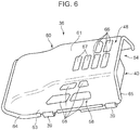
Fig. 6 is a perspective view showing the appearance in which the engine hood is viewed from above; -
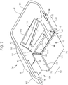
Fig. 7 is a perspective view in which the engine hood is viewed from below; -
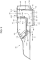
Fig. 8 is a cross-sectional diagram taken along VIII-VIII ofFig. 5 ; -
Fig. 9 is a cross-sectional diagram taken along IX-IX ofFig. 4 ; -
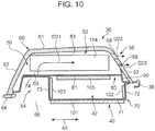
Fig. 10 is a cross-sectional diagram taken along X-X ofFig. 4 ; and -
Fig. 11 is a cross-sectional diagram taken along XI-XI ofFig. 4 . - A preferred embodiment of the present invention is now described with reference to the drawings.
-
Fig. 1 shows ahydraulic shovel 10 according to the embodiment. Thishydraulic shovel 10 is an example of a construction machine to which the present invention is employed. The construction machine is not limited to thehydraulic shovel 10. The present invention can be employed widely to construction machines each including an engine and an engine room for housing the engine wherein a cooled object and a cooling fan are also housed in the engine room. - The
hydraulic shovel 10 includes alower traveling body 12, anupper slewing body 14 mounted in a revolvable manner on the lower travelingbody 12, and awork attachment 16 supported on theupper slewing body 14. Theupper slewing body 14 includes anoperation room 18, anengine room 20, acounterweight 22. - The
engine room 20 forms a rear portion of theupper slewing body 14 and houses anengine 24, ahydraulic pump 26, aheat exchanger 28, acooling fan 30 and the like, as shown inFig. 2 . - The
engine 24 includes anengine output shaft 25 and is disposed inside theengine room 20 in such an attitude that theengine output shaft 25 is parallel to a first horizontal direction indicated by the arrow A1 inFig. 2 (andFigs. 7 to 9 ), that is, a lateral direction of theupper slewing body 14 in the present embodiment. In other words, theengine 24 is laid down in theengine room 20 in such a horizontal attitude that theengine 24 is perpendicular to a horizontal direction perpendicular to the first horizontal direction, namely, a second horizontal direction indicated by the arrow A2 inFig. 3 (andFigs. 7 ,8 and10 ) or, that is, a front-back direction of theupper slewing body 14 in the present embodiment. Thehydraulic pump 26 is coupled to theengine 24 and driven by theengine 24 to thereby discharge hydraulic oil. - The
heat exchanger 28 is a cooled object, which is an object to be cooled, for example, a radiator. - The
cooling fan 30 has a plurality ofblades 31 connected to theengine output shaft 25 as shown inFig. 3 and afan shroud 32 which is not shown inFig. 3 . The plurality ofblades 31 are rotated in synchronization with the rotation of theengine output shaft 25, thereby forming flows of air for cooling the heat exchanger 28: specifically, an axial flow Fx from theheat exchanger 28 to theengine 24 in parallel to theengine output shaft 25 as shown inFig. 2 and a rotational flow Fs along the rotational direction of the plurality ofblades 31 around theengine output shaft 25 as shown inFig. 3 . - The
engine room 20 has an external wall enclosing an internal space for housing theengine 24 and the like. The external wall includes an external-wallmain body 34 and anengine hood 36. - The external-wall
main body 34 is substantially in the shape of a rectangular cuboid in the present embodiment and includes atop wall 35 defining the internal space at upper side thereof. Thetop wall 35 is formed with anopening 37 for opening the internal space upward. - The
engine hood 36, which corresponds to an upper wall portion on the upper side of the internal space, is attached to thetop wall 35 so as to open and close theopening 37. Specifically, as shown inFig. 3 , theengine hood 36 is connected to an edge portion of thetop wall 35 by a plurality ofhinges 39; the edge portion is a part of an edge surrounding theopening 37 and located rearward of the opening 37 (on the right-hand side ofFig. 3 ). Thehinges 39 support the rear edge of theengine hood 36 so as to allow theengine hood 36 to make rotational movement about an axis parallel to the first horizontal direction. The rotational movement allows theengine hood 36 to move between the closed position in which theengine hood 36 closes the opening 37 (shown by the solid line inFig. 1 ) and the open position in which theengine hood 36 opens the opening 37 (shown by the two-dot chain line inFig. 1 ), as shown inFigs. 2 and3 . - This construction machine also includes an exhaust
gas treatment device 29 for purifying the exhaust gas of theengine 24. In the present embodiment, the exhaustgas treatment device 29 is disposed so as to protrude upward beyond thetop wall 35, as shown inFig. 2 , and adjacent to theengine hood 36 on the right side (the left-hand side ofFig. 2 ) thereof.Fig. 2 shows only a housing in the shape of a substantially rectangular cuboid, which is one of elements included in the exhaustgas treatment device 29. - The external-wall
main body 34 is formed with a not-graphically shown inlet port through which air outside theengine room 20 is introduced into the space within theengine room 20. Meanwhile, theengine hood 36 is formed with, as one of the features of this construction machine, afirst exhaust duct 40 and asecond exhaust duct 50 having respective air flow paths independent from each other. Each of the first andsecond exhaust ducts fan 30 is driven to introduce the outside air into theengine room 20 through the inlet port by the rotation of the plurality ofblades 31 to create the axial flow Fx and the rotational flow Fs and further to discharge air having been used to cool theheat exchanger 28 to the outside of theengine room 20 through the first andsecond exhaust ducts - Next will be described the basic configurations of the first and
second exhaust ducts Figs. 4 to 11 and then will be described the members for specifically forming the first andsecond exhaust ducts - The
first exhaust duct 40 has anupstream portion 42 and adownstream portion 44 that are connected to each other in series. - The
upstream portion 42, which extends in the first horizontal direction indicated by the arrow A1, is located downstream of the coolingfan 30 with respect to the direction of the axial flow Fx created by the coolingfan 30. Theupstream portion 42 has an upstream end (a left end inFig. 9 ) and a downstream end (a right end inFig. 9 ), wherein the upstream end surrounds afirst air inlet 46 and the downstream end configures aterminal end 43 closed with respect to the first horizontal direction. - The
downstream portion 44 extends upward from theterminal end 43 of theupstream portion 42. Thedownstream portion 44 has an upper end, namely, a downstream end thereof, which reaches afirst air outlet 48. Thefirst air outlet 48 is opened to the outside of theengine hood 36, specifically, toward the space above theengine hood 36. - The
first exhaust duct 40 allows air to flow as indicated by the arrows D11, D12 shown inFigs. 9 and11 . Specifically, thefirst exhaust duct 40 enables the air to flow from thefirst air inlet 46 through the inside of theupstream portion 42 along the first horizontal direction and further to flow upward from theterminal end 43 of theupstream portion 42 through the inside of the downstream portion 44 (the arrow D11), thereby allowing the air to be discharged upward to the outside of theengine hood 36 through the first air outlet 48 (the arrow D12). - The
second exhaust duct 50 includes across portion 52. Thecross portion 52 crosses theupstream portion 42 of thefirst exhaust duct 40 along the second horizontal direction indicated by the arrow A2, at a position on the upper side of theupstream portion 42, preferably a position just above theupstream portion 42. - The
second exhaust duct 50 has asecond air inlet 56 and asecond air outlet 58. Thesecond air inlet 56 is opened downward at a position sideward of theupstream portion 42 of thefirst exhaust duct 40 with respect to the second horizontal direction. Thesecond air outlet 58 is opened toward a space sideward of theengine hood 36 and outside of theengine hood 36, at a position opposite to the foregoing air inlet across thecross portion 52 of theengine hood 36. - Specifically, the
second exhaust duct 50 according to the present embodiment has an inlet-side portion 54 in addition to thecross portion 52. The inlet-side portion 54 is located downward of anupstream end portion 53 of thecross portion 52 and has a function of guiding the air of theengine room 20 upward from thesecond air inlet 56 to theupstream end portion 53. - The
cross portion 52 enables air to flow as indicated by the arrows D21, D22 shown inFig. 10 , independently of theupstream portion 42 and thedownstream portion 44 of thefirst exhaust duct 40. Specifically, thecross portion 52 enables the air introduced to theupstream end portion 53 to flow along thecross portion 52, i.e., along the second horizontal direction through the upper side of theupstream portion 42 of thefirst exhaust duct 40, to reach the second air outlet 58 (the arrow D21), thereby allowing the air to be discharged sideward through the second air outlet 58 (the arrow D22). - As the members for constructing the first and
second exhaust ducts engine hood 36 includes ahood wall 60, afirst duct member 70, asecond duct member 80, and anauxiliary support member 90. - The
hood wall 60, which configures the shell of theengine hood 36, bulges upward beyond the upper surface of thetop wall 35 while closing theopening 37 in the state where theengine hood 36 is in the closed position as shown inFigs. 2 and3 . Thehood wall 60, thus, has a shape enclosing a hood internal space having a predetermined capacity and located over theopening 37. - Specifically, the
hood wall 60 integrally includes atop wall portion 61, afront wall portion 62, and arear wall portion 63. Thetop wall portion 61 has a curved-surface-like shape covering continuously the hood internal space at the upper side and the left-hand side in the upper slewing body 14 (the right-hand side ofFig. 2 and the left-hand sides ofFigs. 5 and9 ). Thefront wall portion 62 and therear wall portion 63 cover the hood internal space on the front side and rear side in theupper slewing body 14, respectively, and are integrated with thetop wall portion 61 through a smooth curve. - The
hood wall 60, therefore, has a lower edge surrounding a lower opening located at a lower end of thehood wall 60 and a right edge surrounding a right opening located at a right end of the hood wall 60 (the right ends inFigs. 5 and9 ). The lower edge (precisely, a portion of the lower edge other than a part coupled to the hinges 39) and the right edge are provided with alower seal material 64 and aright seal material 65, respectively. The lower andright seal materials engine hood 36 is in the closed position. Specifically, thelower seal material 64 makes close contact with an upper surface of an open rim portion surrounding theopening 37 in thetop wall 35, in the closed state, and theright seal material 65 makes close contact with a side wall of the housing of the exhaustgas treatment device 29, in the closed state. - As shown in
Figs. 4 to 6 , thetop wall portion 61 is formed with a plurality offirst openings 66 configuring thefirst air outlet 48 of thefirst exhaust duct 40, and therear wall portion 63 is formed with a plurality ofsecond openings 68 configuring thesecond air outlet 58 of thesecond exhaust duct 50. In addition to the plurality offirst openings 66, thetop wall portion 61 is also formed with a plurality ofauxiliary openings 67 for complement of the outlet opening area of thesecond exhaust duct 50 separately from thesecond air outlet 58. - The
auxiliary support member 90, which is a member for auxiliary supporting the first andsecond duct members rear wall portion 63 of thehood wall 60 and is fixed to the lower edge. - The
first duct member 70 is a member for forming mainly thefirst exhaust duct 40. Thefirst duct member 70 has abottom plate portion 71, a firstside plate portion 72, a secondside plate portion 73, a connectingplate portion 74, and avertical plate portion 75, wherein thebottom plate portion 71, the first and secondside plate portions plate portion 74 are formed of a single plate member. - The
bottom plate portion 71 configures a bottom wall of theupstream portion 42 of thefirst exhaust duct 40. Specifically, thebottom plate portion 71 has a flat-plate-like shape extending along the first horizontal direction and has a smaller width than that of a lower end opening of the hood wall 60 (the size in the second horizontal direction). - The first
side plate portion 72 configures a side wall which is one of the side walls of theupstream portion 42 and located on opposite side to the second air inlet 56 (on the rear side in the front-back direction of theupper slewing body 14, in the present embodiment). Specifically, the firstside plate portion 72 is disposed upright, having a lower end portion integrated with a front end portion of theboom plate portion 71 and an upper end portion connected to theauxiliary support member 90. - The second
side plate portion 73 configures a side wall which is the other side wall of theupstream portion 42 and located in the vicinity of the second air inlet 56 (the front side of theupper slewing body 14, in the present embodiment). Specifically, the secondside plate portion 73 is disposed upright while spaced with the firstside plate portion 72 in the second horizontal direction, having a lower end portion integrated with a rear end portion of thebottom plate portion 71 and an upper end portion integrated with the connectingplate portion 74. - The connecting
plate portion 74 configures an auxiliary wall interconnecting an upper end of the secondside plate portion 73 and thefront wall portion 62 of thehood wall 60. Specifically, the connectingplate portion 74 has an inner end portion integrally joined with the upper end portion of the secondside plate portion 73 and an outer end portion connected to thefront wall portion 62 of thehood wall 60. - The
vertical plate portion 75 configures a terminal end wall which closes theterminal end 43 of theupstream portion 42 of thefirst exhaust duct 40 with respect to the first horizontal direction, and also configures a side wall which is one of the side walls of thedownstream portion 44 of thefirst exhaust duct 40 and which is connected to the terminal end wall. Specifically, thevertical plate portion 75 is formed of a single plate member disposed upright, and is disposed so as to close respective flow paths formed in theupstream portion 42 and thedownstream portion 44, across theseportions upper slewing body 14, (that is, so as to define the right side of the flow paths). - The
second duct member 80 is a member for forming mainly thesecond exhaust duct 50. Thesecond duct member 80 has abottom plate portion 81, a firstside plate portion 82, and a secondside plate portion 83. - The
bottom plate portion 81 has a shape of a horizontal flat plate and configures a bottom wall of thecross portion 52 of thesecond exhaust duct 50, wherein a part of thebottom plate portion 81 in the first horizontal direction (a right-side portion 81a, in the present embodiment) configures a top wall of theupstream portion 42 of thefirst exhaust duct 40. In other words, the right-side portion 81a of thebottom plate portion 81 functions as an upstream partition wall to separate thecross portion 52 and theupstream portion 42 vertically from each other. The size of thebottom plate portion 81 in the second horizontal direction is approximately equivalent to the size of thebottom plate portion 71 of thefirst duct member 70 in the same direction. Thus kept is agap 55 shown inFig. 7 between thefront wall portion 62 and an edge which is one of the both edges of thebottom plate portion 81 with respect to the second horizontal direction and which is closer to thefront wall portion 62. Thisgap 55 allows air to flow into theupstream end portion 53 of thecross portion 52 through thegap 55. - The first
side plate portion 82 configures a side wall which is one of the side walls of thecross portion 52 and which is located on the opposite side to thedownstream portion 44 of the first exhaust duct 40 (on the left-hand side of theupper slewing body 14, in the present embodiment). Specifically, the firstside plate portion 82 is inclined so as to be displaced outward as extending upward (on the left-hand side of the upper slewing body 14), having a lower end portion integrally joined with a left end portion of thebottom plate portion 81 and an upper end portion connected to thetop wall portion 61 of thehood wall 60. - The second
side plate portion 83 configures the other side wall of thecross portion 52 and also configures a left side wall of thedownstream portion 44 of thefirst exhaust duct 40, i.e., a side wall opposed to thevertical plate portion 75. Specifically, the secondside plate portion 83 is disposed upright so as to function as a downstream partition wall to separate thecross portion 52 and thedownstream portion 44 in the first horizontal direction from each other, having a lower end portion integrally joined with a right end portion of thebottom plate portion 81 and an upper end portion connected to thetop wall portion 61 of thehood wall 60. - Furthermore, in the present embodiment, the edge which is one of the both edges of the
bottom plate portion 81 in the first horizontal direction and located on an opposite side to the downstream portion 44 (the left edges inFigs. 8 and9 ) is inclined in such a direction that the edge is far away from thedownstream portion 44 in the first horizontal direction as extending toward thesecond air outlet 58, and the firstside plate portion 82 is also inclined in the same manner. Thecross portion 52 is thus given such a shape that the width of thecross portion 52, i.e., the size thereof in the first horizontal direction, increases as close to thesecond air outlet 58, specifically, the shape widen in the first horizontal direction as close to thesecond air outlet 58 beyond theupstream portion 42 of thefirst exhaust duct 40. - Moreover, the first and
second exhaust ducts exhaust ducts first exhaust duct 40 include, for example,sound absorption members bottom plate portion 71, an inner surface of the firstside plate portion 72, an inner surface of the secondside plate portion 73, an inner surface of thevertical plate portion 75, a lower surface of the right-side portion 81a of thebottom plate portion 81 and an inner surface of the secondside plate portion 83, respectively. The sound absorption members provided in thesecond exhaust duct 50 include, for example,sound absorption members bottom plate portion 81, lower and upper surfaces of the firstside plate portion 82, and the inner surface of the secondside plate portion 83, respectively. - The foregoing structure, wherein the
first exhaust duct 40 includes, in addition to theupstream portion 42 extending in the first horizontal direction, thedownstream portion 44 extending upward from theterminal end 43 of theupstream portion 42, the upper end of thedownstream portion 44 forming thefirst air outlet 48 opened upward, allows air to be well discharged through thefirst air outlet 48 even if the exhaustgas treatment device 29 or other components exists in the vicinity of thefirst air outlet 48. Moreover, thecross portion 52 of thesecond exhaust duct 50 different from thefirst exhaust duct 40 is formed by effective utilization of a dead space as a result of the shape of thefirst exhaust duct 40, i.e., a space immediately above theupstream portion 42, which is located lateral to the downstream portion 44 (to the left inFig. 9 ), thecross portion 52 enabling the air to flow across the space immediately above theupstream portion 42, from thesecond air inlet 56 of thesecond exhaust duct 50, independently of thefirst exhaust duct 40, to reach thesecond air outlet 58. This allows both of the first andsecond exhaust ducts engine hood 36 or the entire height of the engine room, thereby allowing a large total exhaust flow path area to be created without deteriorating the noise suppression effect. In other words, differently from simple increase in the flow path area of a single exhaust duct, the increase involving deterioration in the noise suppression effect, the arrangement of both of the first andsecond exhaust ducts exhaust duct - In addition, the
cross portion 52 according to the present embodiment, having such a shape that the size in the first horizontal direction increases as extending from thesecond air inlet 56 toward thesecond air outlet 58, can reduce the difference between respective opening areas of thesecond air outlet 58 and thesecond air inlet 56 to thereby a favorable flow of air in the second exhaust duct to be ensured even in the case where the opening area of the plurality ofsecond openings 68 configuring thesecond air outlet 58 is limited due to the shape of theengine hood 36, for example, in the case where the vertical size of each of thesecond openings 68 is limited due to the presence of the curved portion of an upper end of therear wall portion 63. - Specifically, it is preferred that the difference between respective opening areas of the
second air inlet 56 and thesecond air outlet 58 is small because a significantly smaller opening area of thesecond air outlet 58 than that of thesecond air inlet 56 would generate a so-called orifice phenomenon in thesecond air outlet 58 to thereby prevent a sufficient noise suppression effect from being obtained; however, there can be a case where each of the plurality ofsecond openings 68 configuring thesecond air outlet 58 is unable to have a large height. On contrast, thecross portion 52 having such a shape that the size thereof in the first horizontal direction increases as extending from thesecond air inlet 56 toward thesecond air outlet 58 enables the width of thesecond air outlet 58 to be greater than the width of thesecond air inlet 56 to allow the opening area of thesecond air outlet 58 to be close to that of the second air inlet, even with a significant limitation in increase in the opening area of thesecond air outlet 58. - In addition, the
engine hood 36 according to the present embodiment includes a shared wall configuring a part of a wall of thefirst exhaust duct 40 while configuring a part of a wall of thesecond exhaust duct 50, specifically: the right-side portion 81a of thebottom plate portion 81 which vertically separates theupstream portion 42 of thefirst exhaust duct 40 and thecross portion 52 of thesecond exhaust duct 50 from each other to configure both the top wall of theupstream portion 42 and the bottom wall of thecross portion 52; and the secondside plate portion 83 that separates thedownstream portion 44 of thefirst exhaust duct 40 and thecross portion 52 of thesecond exhaust duct 50 in the first horizontal direction from each other to configure a side wall of thedownstream portion 44 and a side wall of thecross portion 52. Thus sharing a part of the wall of thefirst exhaust duct 40 and a part of the wall of thesecond exhaust duct 50 allows the weight of theengine hood 36 to be reduced and allows theengine hood 36 to have a reduced size by the vicinity of the first andsecond exhaust ducts - On the other hand, the present embodiment includes: the second
side plate portion 72 which is one of the first and secondside plate portions upstream portion 42 of thefirst exhaust duct 40 therebetween and which is closer to thesecond air inlet 56 than the firstside plate portion 72; and thefront wall portion 62 of thehood wall 60 located outside the secondside plate portion 73, the secondside plate portion 73 and thefront wall portion 62 constituting the inlet-side portion 54 located below theupstream end portion 53 of thecross portion 52 of the second exhaust duct 50: this makes it possible to guide the air flowing under thecross portion 52 to theupstream end portion 53 of thecross portion 52 with no addition of elements. - The specific structures of the first and second exhaust ducts according to the present invention are not limited to the structures according to the foregoing embodiment. The first and second exhaust ducts may be formed of respective members that are completely independent from each other.
- The present invention permits the first horizontal direction and the second horizontal direction to be set freely. Meanwhile, it is preferable to set the first horizontal direction to be parallel to the axial direction of the
engine output shaft 25 as described above. This arrangement enables the axial flow Fx generated by the coolingfan 30 to promote the flow of air into theupstream portion 42 of thefirst exhaust duct 40 and also enables the rotational flow Fs generated by the coolingfan 30 to promote the flow of air in thecross portion 52 of thesecond exhaust duct 50. - In this case, it is further preferable that the
second air outlet 58 be provided above a position where a tangential direction of the rotational flow Fs is upward (on the left-hand side inFigs. 3 and10 ), as shown inFigs. 3 ,10 and the like. This allows the discharge of air through thesecond air outlet 58 to be further enhanced. - The upstream portion of the first exhaust duct and the cross portion of the second exhaust duct according to the invention do not have to be completely horizontal. These portions may be more or less inclined, provided as long as these portions can possess the function of guiding the air along substantially the horizontal direction.
- As described above, provided is a construction machine including an engine and an engine room for housing the engine, the engine room having an upper portion formed with an exhaust duct, the exhaust duct being capable of allowing air to be favorably discharged through an air outlet formed at the terminal end of the exhaust duct and having a large flow path area without deteriorating the noise suppression effect.
- Provided is a construction machine, including: an engine; an engine room having an external wall enclosing an internal space for housing the engine; a cooled object disposed in the internal space of the engine room; and a cooling fan that is driven to produce cooling air flow for cooling the cooled object in the internal space of the engine room. The external wall of the engine room includes an upper wall portion located on an upper side of the internal space, the upper wall portion being formed with a first exhaust duct and a second exhaust duct for guiding air inside the internal space to an outside of the engine room. The first exhaust duct includes an upstream portion extending in a first horizontal direction and having one end which forms a first air inlet and a downstream portion extending upward from a terminal end of the upstream portion to a first air outlet opened upward in the upper wall portion, the first exhaust duct allowing air to flow from the first air inlet to the first air outlet. The second exhaust duct includes a cross portion crossing the upstream portion of the first exhaust duct on an upper side of the upstream portion in a second horizontal direction perpendicular to the first horizontal direction, the second exhaust duct having a second air inlet opened downward at a position sideward of the upstream portion of the first exhaust duct with respect to the second horizontal direction and a second air outlet opened laterally at a position opposite to the air inlet across the cross portion in the upper wall portion. The cross portion allows air to flow from the second air inlet to the second air outlet through an upper side of the upstream portion of the first exhaust duct.
- Note that the expressions "extending in the first horizontal direction" and "crossing in the second horizontal direction" specify that each of the upstream portion of the first exhaust duct and the cross portion of the second exhaust duct has a shape substantially along a horizontal direction so as to be able to guide the air in the horizontal direction, not intending to exclude one whose wall constituting the upstream portion or the cross portion is inclined with respect to a horizontal surface.
- According to this construction machine, the first exhaust duct includes, in addition to the upstream portion extending in the first horizontal direction, the downstream portion extending upward from the terminal end of this upstream portion, the downstream portion having an upper end which configures the first air outlet that is opened upward; this allows air to be favorably discharged through the first air outlet, even if other devices and structures exists in the vicinity of the first air outlet. Moreover, the cross portion of the second exhaust duct different from the first exhaust duct is formed with effective utilization of a dead space formed due to the shape of the first exhaust duct, i.e., a space located immediately above the upstream portion and sideward of the downstream portion, the cross portion allowing the air to flow across the space immediately above the upstream portion, from the second air inlet of the second exhaust duct, to reach the second air outlet; this allows the first and second exhaust ducts to be arranged independently from each other without significant increase in the entire height of the engine room. This makes it possible, differently from enlarging the flow path area of a single exhaust duct, to create a large total flow path area of the first and second exhaust ducts without deteriorating the noise suppression effect.
- In the case of the construction machine where the engine has an engine output shaft and the cooling fan includes a plurality of blades that are coupled to the engine output shaft so as to be rotated about a fan rotational axis parallel to the axial direction of the engine output shaft, and where the plurality of blades is rotated to thereby form an axial flow in a direction parallel to an axial direction of the engine output shaft and a rotational flow around the axis parallel to the axial direction of the engine output shaft, it is preferred that the first horizontal direction be parallel to the axial direction of the engine output shaft. Of the flows of air formed by the cooling fan, the axial flow in the direction parallel to the axial direction of the engine output shaft, that is, in the first horizontal direction, promotes the flow of air to the upstream portion of the first exhaust duct extending in the first horizontal direction, while the presence of the rotational flow around the axis parallel to the first horizontal direction promotes the flow of air in the cross portion of the second exhaust duct crossing the upstream portion in the second horizontal direction perpendicular to the first horizontal direction, on the upper side thereof.
- In this case, it is more preferable that the second air outlet of the second exhaust duct be provided upward of the position where the tangential direction of the rotational flow is upward. This makes the promotion of the discharge of the rotational flow of air through the second air more remarked.
- Although the first and second exhaust ducts may be formed from members that are completely independent from each other, it is more preferable that the upper wall portion of the engine room include at least one shared wall that configures both a part of a wall of the first exhaust duct and a part of a wall of the second exhaust duct. Inclusion of the shared wall, i.e., the share of a part of the wall of the first exhaust duct and a part of the wall of the second exhaust duct, contributes to reduced weight of the upper wall portion and further contribute reduced size of the upper wall portion by arrangement of the first and second exhaust ducts close to each other.
- Preferable examples of the at least one shared wall described above include: an upstream partition wall that vertically separates the upstream portion of the first exhaust duct and the cross portion of the second exhaust duct from each other to configure both of the top wall of the upstream portion and the bottom wall of the cross portion; and a downstream partition wall that separates the downstream portion of the first exhaust duct and the cross portion of the second exhaust duct from each other in the first horizontal direction to configure both of a side wall of the downstream portion and a side wall of the cross portion.
- It is also preferable: that the upper wall portion includes a pair of opposition side walls opposed to each other in the second horizontal direction across the upstream portion of the first exhaust duct therebetween and an external side wall located on an outer side of one side wall of the opposition side walls, the one side wall being closer to the second air inlet; and that the opposition side wall closer to the second air inlet and the external side wall constitute an inlet-side portion which is a part of the second exhaust duct and located under an upstream end portion of the cross portion of the second exhaust duct. This inlet-side portion is capable of guiding the air flowing under the cross portion to the upstream end portion of the cross portion.
- The specific shapes of the first and second exhaust ducts can be set as appropriate: it is preferable that the cross portion of the second exhaust duct has a shape having a size in the first horizontal direction, the size increasing as the cross portion extends from the second air inlet toward the second air outlet. The shape makes it possible to create a favorable flow of air in the second exhaust duct by reducing the difference between the opening area of the second air outlet and the opening area of the second air inlet, even in the case where the shape of the upper wall portion imposes a limitation in the opening area of the second air outlet opened in the upper wall portion. If the opening area of the second air outlet was significantly smaller than the opening area of the second air inlet, a so-called orifice phenomenon would occur in the second air outlet to prevent a noise suppressing effect from being sufficiently obtained; in contrast, the shape of the cross portion having a size in the first horizontal direction, the size increasing as the cross portion extends from the second air inlet toward the second air outlet as described above, allows the opening area of the second air outlet to be close to the opening area of the second air inlet, regardless of the limitation in increasing the opening area of the second air outlet.
Claims (8)
- A construction machine (10), comprising:an engine (24);an engine room (20) having an external wall enclosing an internal space for housing the engine (24);a cooled object (28) disposed in the internal space of the engine room (20); anda cooling fan (30) that is driven to produce cooling air flow for cooling the cooled object (28) in the internal space of the engine room (20), wherein:the external wall of the engine room (20) includes an upper wall portion (36) located on an upper side of the internal space, the upper wall portion (36) being formed with a first exhaust duct (40) for guiding air inside the internal space to an outside of the engine room (20);characterized in thatthe first exhaust duct (40) includes an upstream portion (42) extending in a first horizontal direction (A1) and having one end which forms a first air inlet (46) and a downstream portion extending upward from a terminal end (43) of the upstream portion (42) to a first air outlet (48) opened upward in the upper wall portion (36), the first exhaust duct (40) allowing air to flow from the first air inlet (46) to the first air outlet (48);the upper wall portion (36) is formed with a second exhaust duct (50) for guiding air inside the internal space to an outside of the engine room (20); andthe second exhaust duct (50) includes a cross portion (52) crossing the upstream portion (42) of the first exhaust duct (40) on an upper side of the upstream portion (42) in a second horizontal direction (A2) perpendicular to the first horizontal direction (A1), the second exhaust duct (50) having a second air inlet (56) opened downward at a position sideward of the upstream portion (42) of the first exhaust duct (40) with respect to the second horizontal direction (A2) and a second air outlet (58) opened sideward at a position opposite to the air inlet across the cross portion (52) in the upper wall portion (36), the cross portion (52) allowing air to flow from the second air inlet (56) to the second air outlet (58) through an upper side of the upstream portion (42) of the first exhaust duct (40).
- The construction machine (10) according to claim 1, wherein: the engine (24) has an engine output shaft (25); the cooling fan (30) includes a plurality of blades (31) coupled to the engine output shaft (25) so as to be rotated about a fan rotational axis parallel to an axis of the engine output shaft (25); the plurality of blades (31) are rotated to thereby form an axial flow (Fx) in a direction parallel to the axial direction of the engine output shaft (25) and a rotational flow (Fs) around the axis parallel to the axial direction of the engine output shaft (25); and the first horizontal direction (A1) is parallel to the axial direction of the engine output shaft (25).
- The construction machine (10) according to claim 2, wherein the second air outlet (58) of the second exhaust duct (50) is provided above a position where a tangential direction of the rotational flow (Fs) is upward.
- The construction machine (10) according to any one of claims 1 to 3, wherein the upper wall portion (36) of the engine room (20) includes at least one shared wall (81a, 83) that configures both a part of a wall of the first exhaust duct (40) and a part of a wall of the second exhaust duct (50).
- The construction machine (10) according to claim 4, wherein the at least one shared wall (81a) includes an upstream partition wall that vertically partitions the upstream portion (42) of the first exhaust duct (40) and the cross portion (52) of the second exhaust duct (50) from each other to configure both of a top wall of the upstream portion (42) and a bottom wall of the cross portion (52).
- The construction machine (10) according to claim 4 or 5, wherein the at least one shared wall (83) includes a downstream partition wall that partitions the downstream portion (44) of the first exhaust duct (40) and the cross portion (52) of the second exhaust duct (50) from each other in the first horizontal direction (A1) to configure both a side wall of the downstream portion (44) and a side wall of the cross portion (52).
- The construction machine (10) according to any one of claims 1 to 6, wherein: the upper wall portion (36) includes a pair of opposition side walls (72, 73) opposed to each other in the second horizontal direction (A2) across the upstream portion (42) of the first exhaust duct (40) therebetween and an external side wall (62) located on an outer side of one side wall (73) of the opposition side walls (72, 73), the one side wall (73) being closer to the second air inlet (56); and the opposition side wall (73) closer to the second air inlet (56) and the external side wall (62) constitute an inlet-side portion (54) which is a part of the second exhaust duct (50) and located under an upstream end portion (53) of the cross portion (52) of the second exhaust duct (50).
- The construction machine (10) according to any one of claims 1 to 7, wherein the cross portion (52) of the second exhaust duct (50) has a shape having a size in the first horizontal direction (A1), the size increasing as the cross portion (52) extends from the second air inlet (56) toward the second air outlet (58).
Applications Claiming Priority (1)
| Application Number | Priority Date | Filing Date | Title |
|---|---|---|---|
| JP2015115375A JP6229694B2 (en) | 2015-06-08 | 2015-06-08 | Construction machine with engine |
Publications (2)
| Publication Number | Publication Date |
|---|---|
| EP3103929A1 EP3103929A1 (en) | 2016-12-14 |
| EP3103929B1 true EP3103929B1 (en) | 2018-08-22 |
Family
ID=55910806
Family Applications (1)
| Application Number | Title | Priority Date | Filing Date |
|---|---|---|---|
| EP16167927.9A Active EP3103929B1 (en) | 2015-06-08 | 2016-05-02 | Construction machine with engine |
Country Status (3)
| Country | Link |
|---|---|
| US (1) | US9518373B1 (en) |
| EP (1) | EP3103929B1 (en) |
| JP (1) | JP6229694B2 (en) |
Families Citing this family (5)
| Publication number | Priority date | Publication date | Assignee | Title |
|---|---|---|---|---|
| WO2018025340A1 (en) * | 2016-08-03 | 2018-02-08 | 株式会社小松製作所 | Work vehicle |
| JP7030435B2 (en) * | 2017-07-18 | 2022-03-07 | 株式会社クボタ | Working machine |
| US10688861B1 (en) * | 2019-03-19 | 2020-06-23 | Cnh Industrial America Llc | Engine airflow adjustment system |
| JP2023023488A (en) * | 2021-08-05 | 2023-02-16 | 株式会社クボタ | work vehicle |
| US20230116011A1 (en) * | 2021-10-12 | 2023-04-13 | Caterpillar Inc. | Secondary control system and method for mounting with service orientation |
Family Cites Families (41)
| Publication number | Priority date | Publication date | Assignee | Title |
|---|---|---|---|---|
| US3788418A (en) * | 1972-04-06 | 1974-01-29 | Caterpillar Tractor Co | System for cooling an hydraulic excavator |
| US4739823A (en) * | 1984-11-09 | 1988-04-26 | Mcdonnell Douglas | Heat exchanger structure |
| JPH08270444A (en) * | 1995-03-31 | 1996-10-15 | Hitachi Constr Mach Co Ltd | Cooling structure of construction equipment |
| JPH08268088A (en) * | 1995-03-31 | 1996-10-15 | Hitachi Constr Mach Co Ltd | Cooling structure of construction equipment |
| JP3622316B2 (en) * | 1996-01-24 | 2005-02-23 | コベルコ建機株式会社 | Construction machine cooling system |
| WO1999015794A1 (en) * | 1997-09-19 | 1999-04-01 | Hitachi Construction Machinery Co., Ltd. | Cooler for construction machinery, and construction machinery |
| JPH11254976A (en) * | 1998-03-11 | 1999-09-21 | Hitachi Constr Mach Co Ltd | Noise reducing device for construction machine and cover and exhaust part used for this device |
| US6167976B1 (en) * | 1998-07-30 | 2001-01-02 | Deere & Company | Engine enclosure |
| JP3399416B2 (en) * | 1999-10-07 | 2003-04-21 | コベルコ建機株式会社 | Construction machine cooling structure |
| JP4450298B2 (en) * | 2000-01-12 | 2010-04-14 | 株式会社小松製作所 | Engine cooling air passage for construction machinery |
| JP2001263964A (en) * | 2000-03-16 | 2001-09-26 | Hitachi Constr Mach Co Ltd | Heat exchanging device for construction equipment |
| US6431299B1 (en) * | 2000-04-05 | 2002-08-13 | Clark Equipment Company | Cooling air ducting for excavator |
| JP2001348909A (en) * | 2000-06-02 | 2001-12-21 | Shin Caterpillar Mitsubishi Ltd | Construction machinery |
| JP3735012B2 (en) * | 2000-07-05 | 2006-01-11 | 日立建機株式会社 | Construction machinery |
| JP2002021565A (en) * | 2000-07-11 | 2002-01-23 | Komatsu Ltd | Engine enclosure for construction vehicle |
| KR100512804B1 (en) * | 2000-12-01 | 2005-09-07 | 히다치 겡키 가부시키 가이샤 | Construction machinery |
| ITTO20020727A1 (en) * | 2002-08-14 | 2004-02-15 | Fiat Kobelco Construction Machinery Spa | COOLING EQUIPMENT FOR A VEHICLE, IN PARTICULAR FOR AN EXCAVATOR. |
| US20040216934A1 (en) * | 2003-01-27 | 2004-11-04 | Kubota Corporation | Working vehicle having a hood |
| JP3952972B2 (en) * | 2003-03-07 | 2007-08-01 | コベルコ建機株式会社 | Construction machine cooling system |
| JP4199584B2 (en) * | 2003-04-10 | 2008-12-17 | 株式会社小松製作所 | Engine room cover for work machine |
| JP4160448B2 (en) * | 2003-05-28 | 2008-10-01 | 新キャタピラー三菱株式会社 | Engine room structure of construction machine and engine cooling device for construction machine |
| WO2004111405A1 (en) * | 2003-06-16 | 2004-12-23 | Kobelco Construction Machinery Co., Ltd. | Construction machine |
| JP4160454B2 (en) | 2003-06-23 | 2008-10-01 | 新キャタピラー三菱株式会社 | Engine hood for construction machinery, engine room structure for construction machinery, and engine cooling device for construction machinery |
| JP2005145114A (en) * | 2003-11-11 | 2005-06-09 | Shin Caterpillar Mitsubishi Ltd | Engine hood of construction machinery, engine room structure of construction machinery, and cooling device of construction machinery |
| JP4539133B2 (en) * | 2004-03-01 | 2010-09-08 | コベルコ建機株式会社 | Exhaust structure of construction machinery |
| KR100894950B1 (en) * | 2004-12-27 | 2009-04-27 | 코벨코 겐키 가부시키가이샤 | Cooling apparatus of construction machine |
| DE602006015057D1 (en) * | 2005-07-05 | 2010-08-05 | Yanmar Co Ltd | CONSTRUCTION MACHINE |
| US7388301B2 (en) * | 2005-10-12 | 2008-06-17 | Kobelco Construction Machinery Co., Ltd. | Construction machine |
| JP4175398B2 (en) * | 2006-06-30 | 2008-11-05 | コベルコ建機株式会社 | Exhaust structure of construction machinery |
| JP4270239B2 (en) * | 2006-08-11 | 2009-05-27 | コベルコ建機株式会社 | Construction machinery |
| JP5172381B2 (en) * | 2008-02-22 | 2013-03-27 | 日立建機株式会社 | Construction machinery |
| JP5699653B2 (en) * | 2010-03-08 | 2015-04-15 | コベルコ建機株式会社 | Construction machine cooling structure |
| JP5172898B2 (en) * | 2010-06-15 | 2013-03-27 | 日立建機株式会社 | Electric construction machine |
| US8893840B2 (en) * | 2011-06-27 | 2014-11-25 | Caterpillar Inc. | Engine enclosure door |
| JP5824961B2 (en) * | 2011-08-19 | 2015-12-02 | コベルコ建機株式会社 | Construction machine cooling system |
| US9255381B2 (en) * | 2011-12-26 | 2016-02-09 | Hitachi Construction Machinery Co., Ltd. | Construction machine |
| JP5948966B2 (en) * | 2012-03-01 | 2016-07-06 | コベルコ建機株式会社 | Construction machine intake structure |
| US8875823B2 (en) * | 2012-07-13 | 2014-11-04 | Deere & Company | Multi-functional cooling system |
| JP5821872B2 (en) * | 2013-02-22 | 2015-11-24 | コベルコ建機株式会社 | Construction machine intake structure |
| JP5850024B2 (en) * | 2013-10-31 | 2016-02-03 | コベルコ建機株式会社 | Work machine |
| JP5962686B2 (en) * | 2014-01-30 | 2016-08-03 | コベルコ建機株式会社 | Electrical equipment cooling structure for construction machinery |
-
2015
- 2015-06-08 JP JP2015115375A patent/JP6229694B2/en active Active
-
2016
- 2016-04-27 US US15/139,378 patent/US9518373B1/en active Active
- 2016-05-02 EP EP16167927.9A patent/EP3103929B1/en active Active
Non-Patent Citations (1)
| Title |
|---|
| None * |
Also Published As
| Publication number | Publication date |
|---|---|
| JP2017002506A (en) | 2017-01-05 |
| EP3103929A1 (en) | 2016-12-14 |
| US20160356017A1 (en) | 2016-12-08 |
| JP6229694B2 (en) | 2017-11-15 |
| US9518373B1 (en) | 2016-12-13 |
Similar Documents
| Publication | Publication Date | Title |
|---|---|---|
| EP3103929B1 (en) | Construction machine with engine | |
| JP5699653B2 (en) | Construction machine cooling structure | |
| EP3103930B1 (en) | Construction machine including engine | |
| JP5831111B2 (en) | Exhaust structure of construction machinery | |
| KR101923759B1 (en) | Construction machine | |
| JP5594197B2 (en) | Construction machine cooling structure | |
| JP2008174004A (en) | Cooling structure of construction machine | |
| EP3315341B1 (en) | Construction machine | |
| JP2008008257A (en) | Exhaust structure of construction machine | |
| JP4160454B2 (en) | Engine hood for construction machinery, engine room structure for construction machinery, and engine cooling device for construction machinery | |
| JP5614071B2 (en) | Engine intake system for construction machinery | |
| US9297144B2 (en) | Work machine | |
| JP2017036538A (en) | Air discharge structure of construction machine | |
| JP4387789B2 (en) | Engine room structure of construction machinery | |
| JP4328221B2 (en) | Construction machine cooling system | |
| JP2017227158A (en) | Engine device | |
| JP2005125951A (en) | Engine hood for construction machine, engine compartment for construction machine and cooling device for construction machine | |
| JP2005145114A (en) | Engine hood of construction machinery, engine room structure of construction machinery, and cooling device of construction machinery | |
| JP2017072095A (en) | Air-discharge structure of construction machine | |
| JP5967058B2 (en) | Piping material for air cleaner | |
| JP2004352066A (en) | Engine room structure of construction machine, and engine cooling device for construction machine |
Legal Events
| Date | Code | Title | Description |
|---|---|---|---|
| PUAI | Public reference made under article 153(3) epc to a published international application that has entered the european phase |
Free format text: ORIGINAL CODE: 0009012 |
|
| STAA | Information on the status of an ep patent application or granted ep patent |
Free format text: STATUS: THE APPLICATION HAS BEEN PUBLISHED |
|
| AK | Designated contracting states |
Kind code of ref document: A1 Designated state(s): AL AT BE BG CH CY CZ DE DK EE ES FI FR GB GR HR HU IE IS IT LI LT LU LV MC MK MT NL NO PL PT RO RS SE SI SK SM TR |
|
| AX | Request for extension of the european patent |
Extension state: BA ME |
|
| STAA | Information on the status of an ep patent application or granted ep patent |
Free format text: STATUS: REQUEST FOR EXAMINATION WAS MADE |
|
| 17P | Request for examination filed |
Effective date: 20170208 |
|
| RBV | Designated contracting states (corrected) |
Designated state(s): AL AT BE BG CH CY CZ DE DK EE ES FI FR GB GR HR HU IE IS IT LI LT LU LV MC MK MT NL NO PL PT RO RS SE SI SK SM TR |
|
| REG | Reference to a national code |
Ref country code: DE Ref legal event code: R079 Ref document number: 602016004907 Country of ref document: DE Free format text: PREVIOUS MAIN CLASS: E02F0009080000 Ipc: B62D0025120000 |
|
| GRAP | Despatch of communication of intention to grant a patent |
Free format text: ORIGINAL CODE: EPIDOSNIGR1 |
|
| STAA | Information on the status of an ep patent application or granted ep patent |
Free format text: STATUS: GRANT OF PATENT IS INTENDED |
|
| RIC1 | Information provided on ipc code assigned before grant |
Ipc: B62D 25/12 20060101AFI20180125BHEP Ipc: F01P 5/06 20060101ALI20180125BHEP Ipc: B60K 11/06 20060101ALI20180125BHEP Ipc: E02F 9/08 20060101ALI20180125BHEP Ipc: F01P 11/10 20060101ALI20180125BHEP Ipc: F01P 11/12 20060101ALI20180125BHEP Ipc: B60R 13/08 20060101ALI20180125BHEP |
|
| INTG | Intention to grant announced |
Effective date: 20180222 |
|
| GRAS | Grant fee paid |
Free format text: ORIGINAL CODE: EPIDOSNIGR3 |
|
| GRAA | (expected) grant |
Free format text: ORIGINAL CODE: 0009210 |
|
| STAA | Information on the status of an ep patent application or granted ep patent |
Free format text: STATUS: THE PATENT HAS BEEN GRANTED |
|
| AK | Designated contracting states |
Kind code of ref document: B1 Designated state(s): AL AT BE BG CH CY CZ DE DK EE ES FI FR GB GR HR HU IE IS IT LI LT LU LV MC MK MT NL NO PL PT RO RS SE SI SK SM TR |
|
| REG | Reference to a national code |
Ref country code: GB Ref legal event code: FG4D |
|
| REG | Reference to a national code |
Ref country code: CH Ref legal event code: EP |
|
| REG | Reference to a national code |
Ref country code: AT Ref legal event code: REF Ref document number: 1032134 Country of ref document: AT Kind code of ref document: T Effective date: 20180915 |
|
| REG | Reference to a national code |
Ref country code: IE Ref legal event code: FG4D |
|
| REG | Reference to a national code |
Ref country code: DE Ref legal event code: R096 Ref document number: 602016004907 Country of ref document: DE |
|
| REG | Reference to a national code |
Ref country code: NL Ref legal event code: MP Effective date: 20180822 |
|
| REG | Reference to a national code |
Ref country code: LT Ref legal event code: MG4D |
|
| PG25 | Lapsed in a contracting state [announced via postgrant information from national office to epo] |
Ref country code: BG Free format text: LAPSE BECAUSE OF FAILURE TO SUBMIT A TRANSLATION OF THE DESCRIPTION OR TO PAY THE FEE WITHIN THE PRESCRIBED TIME-LIMIT Effective date: 20181122 Ref country code: SE Free format text: LAPSE BECAUSE OF FAILURE TO SUBMIT A TRANSLATION OF THE DESCRIPTION OR TO PAY THE FEE WITHIN THE PRESCRIBED TIME-LIMIT Effective date: 20180822 Ref country code: GR Free format text: LAPSE BECAUSE OF FAILURE TO SUBMIT A TRANSLATION OF THE DESCRIPTION OR TO PAY THE FEE WITHIN THE PRESCRIBED TIME-LIMIT Effective date: 20181123 Ref country code: RS Free format text: LAPSE BECAUSE OF FAILURE TO SUBMIT A TRANSLATION OF THE DESCRIPTION OR TO PAY THE FEE WITHIN THE PRESCRIBED TIME-LIMIT Effective date: 20180822 Ref country code: NL Free format text: LAPSE BECAUSE OF FAILURE TO SUBMIT A TRANSLATION OF THE DESCRIPTION OR TO PAY THE FEE WITHIN THE PRESCRIBED TIME-LIMIT Effective date: 20180822 Ref country code: IS Free format text: LAPSE BECAUSE OF FAILURE TO SUBMIT A TRANSLATION OF THE DESCRIPTION OR TO PAY THE FEE WITHIN THE PRESCRIBED TIME-LIMIT Effective date: 20181222 Ref country code: NO Free format text: LAPSE BECAUSE OF FAILURE TO SUBMIT A TRANSLATION OF THE DESCRIPTION OR TO PAY THE FEE WITHIN THE PRESCRIBED TIME-LIMIT Effective date: 20181122 Ref country code: FI Free format text: LAPSE BECAUSE OF FAILURE TO SUBMIT A TRANSLATION OF THE DESCRIPTION OR TO PAY THE FEE WITHIN THE PRESCRIBED TIME-LIMIT Effective date: 20180822 Ref country code: LT Free format text: LAPSE BECAUSE OF FAILURE TO SUBMIT A TRANSLATION OF THE DESCRIPTION OR TO PAY THE FEE WITHIN THE PRESCRIBED TIME-LIMIT Effective date: 20180822 |
|
| REG | Reference to a national code |
Ref country code: AT Ref legal event code: MK05 Ref document number: 1032134 Country of ref document: AT Kind code of ref document: T Effective date: 20180822 |
|
| PG25 | Lapsed in a contracting state [announced via postgrant information from national office to epo] |
Ref country code: LV Free format text: LAPSE BECAUSE OF FAILURE TO SUBMIT A TRANSLATION OF THE DESCRIPTION OR TO PAY THE FEE WITHIN THE PRESCRIBED TIME-LIMIT Effective date: 20180822 Ref country code: HR Free format text: LAPSE BECAUSE OF FAILURE TO SUBMIT A TRANSLATION OF THE DESCRIPTION OR TO PAY THE FEE WITHIN THE PRESCRIBED TIME-LIMIT Effective date: 20180822 Ref country code: AL Free format text: LAPSE BECAUSE OF FAILURE TO SUBMIT A TRANSLATION OF THE DESCRIPTION OR TO PAY THE FEE WITHIN THE PRESCRIBED TIME-LIMIT Effective date: 20180822 |
|
| PG25 | Lapsed in a contracting state [announced via postgrant information from national office to epo] |
Ref country code: RO Free format text: LAPSE BECAUSE OF FAILURE TO SUBMIT A TRANSLATION OF THE DESCRIPTION OR TO PAY THE FEE WITHIN THE PRESCRIBED TIME-LIMIT Effective date: 20180822 Ref country code: PL Free format text: LAPSE BECAUSE OF FAILURE TO SUBMIT A TRANSLATION OF THE DESCRIPTION OR TO PAY THE FEE WITHIN THE PRESCRIBED TIME-LIMIT Effective date: 20180822 Ref country code: ES Free format text: LAPSE BECAUSE OF FAILURE TO SUBMIT A TRANSLATION OF THE DESCRIPTION OR TO PAY THE FEE WITHIN THE PRESCRIBED TIME-LIMIT Effective date: 20180822 Ref country code: CZ Free format text: LAPSE BECAUSE OF FAILURE TO SUBMIT A TRANSLATION OF THE DESCRIPTION OR TO PAY THE FEE WITHIN THE PRESCRIBED TIME-LIMIT Effective date: 20180822 Ref country code: EE Free format text: LAPSE BECAUSE OF FAILURE TO SUBMIT A TRANSLATION OF THE DESCRIPTION OR TO PAY THE FEE WITHIN THE PRESCRIBED TIME-LIMIT Effective date: 20180822 Ref country code: AT Free format text: LAPSE BECAUSE OF FAILURE TO SUBMIT A TRANSLATION OF THE DESCRIPTION OR TO PAY THE FEE WITHIN THE PRESCRIBED TIME-LIMIT Effective date: 20180822 |
|
| REG | Reference to a national code |
Ref country code: DE Ref legal event code: R097 Ref document number: 602016004907 Country of ref document: DE |
|
| PG25 | Lapsed in a contracting state [announced via postgrant information from national office to epo] |
Ref country code: SM Free format text: LAPSE BECAUSE OF FAILURE TO SUBMIT A TRANSLATION OF THE DESCRIPTION OR TO PAY THE FEE WITHIN THE PRESCRIBED TIME-LIMIT Effective date: 20180822 Ref country code: DK Free format text: LAPSE BECAUSE OF FAILURE TO SUBMIT A TRANSLATION OF THE DESCRIPTION OR TO PAY THE FEE WITHIN THE PRESCRIBED TIME-LIMIT Effective date: 20180822 Ref country code: SK Free format text: LAPSE BECAUSE OF FAILURE TO SUBMIT A TRANSLATION OF THE DESCRIPTION OR TO PAY THE FEE WITHIN THE PRESCRIBED TIME-LIMIT Effective date: 20180822 |
|
| PLBE | No opposition filed within time limit |
Free format text: ORIGINAL CODE: 0009261 |
|
| STAA | Information on the status of an ep patent application or granted ep patent |
Free format text: STATUS: NO OPPOSITION FILED WITHIN TIME LIMIT |
|
| 26N | No opposition filed |
Effective date: 20190523 |
|
| PG25 | Lapsed in a contracting state [announced via postgrant information from national office to epo] |
Ref country code: SI Free format text: LAPSE BECAUSE OF FAILURE TO SUBMIT A TRANSLATION OF THE DESCRIPTION OR TO PAY THE FEE WITHIN THE PRESCRIBED TIME-LIMIT Effective date: 20180822 |
|
| REG | Reference to a national code |
Ref country code: CH Ref legal event code: PL |
|
| PG25 | Lapsed in a contracting state [announced via postgrant information from national office to epo] |
Ref country code: MC Free format text: LAPSE BECAUSE OF FAILURE TO SUBMIT A TRANSLATION OF THE DESCRIPTION OR TO PAY THE FEE WITHIN THE PRESCRIBED TIME-LIMIT Effective date: 20180822 Ref country code: CH Free format text: LAPSE BECAUSE OF NON-PAYMENT OF DUE FEES Effective date: 20190531 Ref country code: LI Free format text: LAPSE BECAUSE OF NON-PAYMENT OF DUE FEES Effective date: 20190531 |
|
| REG | Reference to a national code |
Ref country code: BE Ref legal event code: MM Effective date: 20190531 |
|
| PG25 | Lapsed in a contracting state [announced via postgrant information from national office to epo] |
Ref country code: LU Free format text: LAPSE BECAUSE OF NON-PAYMENT OF DUE FEES Effective date: 20190502 |
|
| PG25 | Lapsed in a contracting state [announced via postgrant information from national office to epo] |
Ref country code: TR Free format text: LAPSE BECAUSE OF FAILURE TO SUBMIT A TRANSLATION OF THE DESCRIPTION OR TO PAY THE FEE WITHIN THE PRESCRIBED TIME-LIMIT Effective date: 20180822 |
|
| PG25 | Lapsed in a contracting state [announced via postgrant information from national office to epo] |
Ref country code: IE Free format text: LAPSE BECAUSE OF NON-PAYMENT OF DUE FEES Effective date: 20190502 |
|
| PG25 | Lapsed in a contracting state [announced via postgrant information from national office to epo] |
Ref country code: BE Free format text: LAPSE BECAUSE OF NON-PAYMENT OF DUE FEES Effective date: 20190531 |
|
| PG25 | Lapsed in a contracting state [announced via postgrant information from national office to epo] |
Ref country code: PT Free format text: LAPSE BECAUSE OF FAILURE TO SUBMIT A TRANSLATION OF THE DESCRIPTION OR TO PAY THE FEE WITHIN THE PRESCRIBED TIME-LIMIT Effective date: 20181222 |
|
| PG25 | Lapsed in a contracting state [announced via postgrant information from national office to epo] |
Ref country code: CY Free format text: LAPSE BECAUSE OF FAILURE TO SUBMIT A TRANSLATION OF THE DESCRIPTION OR TO PAY THE FEE WITHIN THE PRESCRIBED TIME-LIMIT Effective date: 20180822 |
|
| PG25 | Lapsed in a contracting state [announced via postgrant information from national office to epo] |
Ref country code: MT Free format text: LAPSE BECAUSE OF FAILURE TO SUBMIT A TRANSLATION OF THE DESCRIPTION OR TO PAY THE FEE WITHIN THE PRESCRIBED TIME-LIMIT Effective date: 20180822 Ref country code: HU Free format text: LAPSE BECAUSE OF FAILURE TO SUBMIT A TRANSLATION OF THE DESCRIPTION OR TO PAY THE FEE WITHIN THE PRESCRIBED TIME-LIMIT; INVALID AB INITIO Effective date: 20160502 |
|
| PG25 | Lapsed in a contracting state [announced via postgrant information from national office to epo] |
Ref country code: MK Free format text: LAPSE BECAUSE OF FAILURE TO SUBMIT A TRANSLATION OF THE DESCRIPTION OR TO PAY THE FEE WITHIN THE PRESCRIBED TIME-LIMIT Effective date: 20180822 |
|
| REG | Reference to a national code |
Ref country code: FR Ref legal event code: PLFP Year of fee payment: 8 |
|
| PGFP | Annual fee paid to national office [announced via postgrant information from national office to epo] |
Ref country code: GB Payment date: 20230330 Year of fee payment: 8 |
|
| PGFP | Annual fee paid to national office [announced via postgrant information from national office to epo] |
Ref country code: IT Payment date: 20230412 Year of fee payment: 8 Ref country code: FR Payment date: 20230411 Year of fee payment: 8 Ref country code: DE Payment date: 20230331 Year of fee payment: 8 |